EP3634259B1 - Flow control stent - Google Patents
Flow control stent Download PDFInfo
- Publication number
- EP3634259B1 EP3634259B1 EP18792722.3A EP18792722A EP3634259B1 EP 3634259 B1 EP3634259 B1 EP 3634259B1 EP 18792722 A EP18792722 A EP 18792722A EP 3634259 B1 EP3634259 B1 EP 3634259B1
- Authority
- EP
- European Patent Office
- Prior art keywords
- medical device
- proximal
- saddle region
- cylindrical saddle
- retention member
- Prior art date
- Legal status (The legal status is an assumption and is not a legal conclusion. Google has not performed a legal analysis and makes no representation as to the accuracy of the status listed.)
- Active
Links
Images




Classifications
-
- A—HUMAN NECESSITIES
- A61—MEDICAL OR VETERINARY SCIENCE; HYGIENE
- A61M—DEVICES FOR INTRODUCING MEDIA INTO, OR ONTO, THE BODY; DEVICES FOR TRANSDUCING BODY MEDIA OR FOR TAKING MEDIA FROM THE BODY; DEVICES FOR PRODUCING OR ENDING SLEEP OR STUPOR
- A61M27/00—Drainage appliance for wounds or the like, i.e. wound drains, implanted drains
- A61M27/002—Implant devices for drainage of body fluids from one part of the body to another
-
- A—HUMAN NECESSITIES
- A61—MEDICAL OR VETERINARY SCIENCE; HYGIENE
- A61B—DIAGNOSIS; SURGERY; IDENTIFICATION
- A61B17/00—Surgical instruments, devices or methods
- A61B17/11—Surgical instruments, devices or methods for performing anastomosis; Buttons for anastomosis
-
- A—HUMAN NECESSITIES
- A61—MEDICAL OR VETERINARY SCIENCE; HYGIENE
- A61B—DIAGNOSIS; SURGERY; IDENTIFICATION
- A61B17/00—Surgical instruments, devices or methods
- A61B17/11—Surgical instruments, devices or methods for performing anastomosis; Buttons for anastomosis
- A61B17/1114—Surgical instruments, devices or methods for performing anastomosis; Buttons for anastomosis of the digestive tract, e.g. bowels or oesophagus
-
- A—HUMAN NECESSITIES
- A61—MEDICAL OR VETERINARY SCIENCE; HYGIENE
- A61B—DIAGNOSIS; SURGERY; IDENTIFICATION
- A61B17/00—Surgical instruments, devices or methods
- A61B17/12—Surgical instruments, devices or methods for ligaturing or otherwise compressing tubular parts of the body, e.g. blood vessels or umbilical cord
- A61B17/12022—Occluding by internal devices, e.g. balloons or releasable wires
- A61B17/12027—Type of occlusion
- A61B17/12036—Type of occlusion partial occlusion
-
- A—HUMAN NECESSITIES
- A61—MEDICAL OR VETERINARY SCIENCE; HYGIENE
- A61B—DIAGNOSIS; SURGERY; IDENTIFICATION
- A61B17/00—Surgical instruments, devices or methods
- A61B17/12—Surgical instruments, devices or methods for ligaturing or otherwise compressing tubular parts of the body, e.g. blood vessels or umbilical cord
- A61B17/12022—Occluding by internal devices, e.g. balloons or releasable wires
- A61B17/12027—Type of occlusion
- A61B17/1204—Type of occlusion temporary occlusion
-
- A—HUMAN NECESSITIES
- A61—MEDICAL OR VETERINARY SCIENCE; HYGIENE
- A61B—DIAGNOSIS; SURGERY; IDENTIFICATION
- A61B17/00—Surgical instruments, devices or methods
- A61B17/12—Surgical instruments, devices or methods for ligaturing or otherwise compressing tubular parts of the body, e.g. blood vessels or umbilical cord
- A61B17/12022—Occluding by internal devices, e.g. balloons or releasable wires
- A61B17/12131—Occluding by internal devices, e.g. balloons or releasable wires characterised by the type of occluding device
- A61B17/12168—Occluding by internal devices, e.g. balloons or releasable wires characterised by the type of occluding device having a mesh structure
- A61B17/12172—Occluding by internal devices, e.g. balloons or releasable wires characterised by the type of occluding device having a mesh structure having a pre-set deployed three-dimensional shape
-
- A—HUMAN NECESSITIES
- A61—MEDICAL OR VETERINARY SCIENCE; HYGIENE
- A61B—DIAGNOSIS; SURGERY; IDENTIFICATION
- A61B17/00—Surgical instruments, devices or methods
- A61B17/12—Surgical instruments, devices or methods for ligaturing or otherwise compressing tubular parts of the body, e.g. blood vessels or umbilical cord
- A61B17/12022—Occluding by internal devices, e.g. balloons or releasable wires
- A61B17/12131—Occluding by internal devices, e.g. balloons or releasable wires characterised by the type of occluding device
- A61B17/12168—Occluding by internal devices, e.g. balloons or releasable wires characterised by the type of occluding device having a mesh structure
- A61B17/12177—Occluding by internal devices, e.g. balloons or releasable wires characterised by the type of occluding device having a mesh structure comprising additional materials, e.g. thrombogenic, having filaments, having fibers or being coated
-
- A—HUMAN NECESSITIES
- A61—MEDICAL OR VETERINARY SCIENCE; HYGIENE
- A61B—DIAGNOSIS; SURGERY; IDENTIFICATION
- A61B17/00—Surgical instruments, devices or methods
- A61B17/11—Surgical instruments, devices or methods for performing anastomosis; Buttons for anastomosis
- A61B2017/1139—Side-to-side connections, e.g. shunt or X-connections
Definitions
- the present disclosure relates generally to the field of medical devices and establishing fluid communication between body lumens.
- the present disclosure relates to devices and methods for establishing a controlled flow or access passage between body lumens.
- anastomotic device which facilitates transgastric or transduodenal drainage of a symptomatic pancreatic pseudocyst adherent to the gastric or bowel wall may remain implanted for up to 60 days.
- the open access path provided by the device may allow the continued flow of fluid and/or debris from the pancreatic pseudocyst into the stomach or duodenum.
- Resolution of the pancreatic pseudocyst may be further enhanced by the flow of acidic stomach fluids into the pseudocyst, which neutralize the alkalinity and increase the viscosity of the fluid and/or debris. While continual uni-directional flow or bi-directional flow through the medical device may be advantageous in certain circumstances, various medical conditions require controlled periodic or intermittent drainage and/or access to a body lumen or organ.
- a variety of advantageous medical outcomes may be realized by the devices and/or methods of the present disclosure which allow, for example, infusion and/or drainage of body lumens or organs in a controlled manner for a finite or limited period of time.
- Document US2017252144 A1 discloses a medical device that includes a tubular scaffold.
- the scaffold includes a longitudinal axis, an inner surface and an outer surface.
- the medical device also includes a flexible valve extending radially inward from the inner surface of the scaffold.
- the valve includes an annular chamber extending circumferentially around the inner surface of the scaffold and is configured to shift from a closed configuration to an open configuration.
- Document US2017072173 A1 discloses devices and methods for treating biliary disease including an inflatable shunt configured for deployment between one of a lumen of a gallbladder or gallbladder duct and a second body lumen.
- Document US2016256169 A1 discloses a flow reducing implant for reducing blood flow in a blood vessel having a cross sectional dimension, the flow reducing implant comprising a hollow element adapted for placement in the blood vessel defining a flow passage therethrough, said flow passage comprising at least two sections, one with a larger diameter and one with a smaller diameter, wherein said smaller diameter is smaller than a cross section of the blood vessel.
- astomotic devices e.g ., anastomotic devices, drainage stents, etc.
- medical devices may be used in a variety of medical procedures, including natural orifice transluminal endoscopic surgery (NOTES) procedures, (e.g ., external biliary drain conversion, enteroenterostomy, gastrojejumostomy, gastroduodenostomy and gastroileostomy, transcolonic procedures, transgastric procedures, transtracheal procedures, transvaginal procedures, cholelithiasis procedures, choledocholiathiasis procedures, etc.) to establish and/or maintain a controlled periodic or intermittent flow or access passage from or between a variety of body organs, lumens, ducts, vessels, fistulas, cysts and/or spaces (NOTES) procedures, (e.g ., external bili
- the devices can be inserted via different access points and approaches, e.g. , percutaneously, endoscopically, laparoscopically or some combination thereof.
- the medical devices disclosed herein are self-expanding, but in other embodiments the medical device may be expandable by other means, including, e.g., a balloon catheter.
- such medical devices are not limited to drainage, but may facilitate controlled access to organs, vessels or body lumens for other purposes, such as delivery of therapeutic agents and/or creating a path to divert or bypass fluids or solids from one location to another, removing obstructions and/or non-invasive or minimally invasive manipulation of tissues.
- distal refers to the end farthest away from the medical professional when introducing a device into a patient
- proximal refers to the end closest to the medical professional when introducing a device into a patient
- the present disclosure relates to a medical device (e.g., anastomotic device, drainage stent, etc.) which may allow an efficient mechanism for controlled periodic access to a body lumen or organ to facilitate direct endoscopic delivery of Advanced Therapy Medicinal Products (ATMP's), e.g., immune check-point inhibitors, therapeutic agents, drugs, cellular therapy solutions, etc., for maximal therapeutic effect and minimal patient discomfort.
- a medical device of the present disclosure may support controlled repeated/intermittent endoscopic delivery of immune boosting therapeutic fluids through the stomach or duodenal wall into a body cavity comprising or adjacent to a diseased organ or tissue.
- a medical device 100 of the present disclosure may include an elongate tubular body 110 forming a lumen and comprising a proximal portion 112, a distal portion 122, a length and a diameter.
- the elongate tubular body 110 may include an unexpanded configuration (e.g. , constrained, undeployed or delivery configuration; not shown), and an expanded configuration (e.g., unconstrained, delivered or deployed configuration) where the proximal portion 112 radially expands into a proximal retention member 114, and the distal portion 122 radially expands into a distal retention member 124, leaving a cylindrical saddle region 130 extending therebetween.
- a diameter of the cylindrical saddle region 130 may be greater than a diameter of the elongate tubular body 110 in the unexpanded configuration.
- the proximal and distal retention members 114, 124 may extend radially from ( e.g., perpendicular to a circumference of) the elongate tubular body 110 to define respective surfaces 116, 126.
- the cylindrical saddle region 130 may include a constricted or narrowed portion 138 (e.g., valve) disposed between larger diameter first and second end portions 134, 136.
- the constricted portion 138 may be configured to move between a first diameter (e.g., closed) configuration which limits or prevents the flow of fluids and/or debris therethrough, and a second diameter (e.g., open) configuration larger than the first diameter, which provides an open flow or access passage therethrough.
- a first diameter e.g., closed
- a second diameter e.g., open
- the constricted portion 138 may be configured to move from the first diameter configuration to the second diameter configuration in response to a threshold level of force applied to the constricted portion, e.g., as exerted by a medical device advanced through the cylindrical saddle region 130.
- the medical device 100 may comprise one or more woven, braided and/or knitted filaments, e.g., shape memory materials, which may allow the constricted portion 138 to return to the first diameter configuration upon withdrawal/removal of the medical device from within the cylindrical saddle region 130.
- shape memory materials e.g., shape memory materials
- FIG. 1B provides a front perspective view of the medical device 100, with the constricted portion 138 in the first diameter configuration such that substantially no opening or access passage extends through the cylindrical saddle region.
- the medical device 100 of the present disclosure is not limited to the configuration depicted in FIG. 1A , but may include a variety of different configurations and/or dimensions.
- a medical device 200 of the present disclosure may include proximal and distal retention members 214, 224 and a cylindrical saddle region 230 with first and second end portions 234, 236 that are tapered in diameter toward the center of the cylindrical saddle region and disposed on either side of the constricted portion 238.
- FIG. 1B provides a front perspective view of the medical device 100, with the constricted portion 138 in the first diameter configuration such that substantially no opening or access passage extends through the cylindrical saddle region.
- the medical device 100 of the present disclosure is not limited to the configuration depicted in FIG. 1A , but may include a variety of different configurations and/or dimensions.
- FIG. 3 provides a perspective view of the medical device 100, 200 of the present disclosure disposed over a guidewire 250 in a partially deployed configuration.
- the cylindrical saddle region 130, 230 is depicted as a component of medical devices 100, 200 of the present disclosure, in various embodiments, the cylindrical saddle region configuration may be incorporated into any of the medical devices 300, 400, 500, 600 disclosed herein.
- a medical device 300 of the present disclosure may include the identical, or similar, configuration and elements as medical devices 100, 200, with the exception that the cylindrical saddle region 330 includes a constant inner and outer diameter.
- the medical device 300 may include a plug 331 disposed within the cylindrical saddle region 330.
- the plug 331 may include first and second membranes 333, 334 disposed within a sheath or housing 332 between first and second washers 335, 336.
- the first and second membranes 333, 334 may include one or more slits 333a/b, 334a/b ( FIG.
- the slits 333a/b, 334a/b may be configured to move from the first to second configuration in response to a threshold level of force applied to the first and second membranes 333, 334, e.g., as exerted by a medical device advanced through the proximal retention member and into the cylindrical saddle region.
- the materials e.g.
- first and second membranes 333, 334 which comprise the first and second membranes 333, 334 may allow the slits 333a/b, 334a/b to return to the first configuration upon withdrawal/removal of the medical device from within the plug 331.
- FIG. 4B provides a front perspective view of the medical device 300, with the slits 333a/b of the first membrane 333 in the first configuration such that substantially no opening or access passage extends through the cylindrical saddle region.
- the membranes 333, 334 of the present disclosure are depicted as substantially circular, in various embodiments, the plug 331 may include any number of membranes ( e.g., a single membrane, three or more membranes, etc.) with a variety of sizes, shapes, configurations and/or thicknesses.
- the slits 333a/b, 334a/b formed within the membranes 333, 334 are depicted as a pair of slits intersecting in an "X" or crosshair configuration, in various embodiments, the number, length, arrangement and/or orientation of the slits may vary.
- the plug 331 may be assembled by positioning the first and second membranes 333, 334 within the sheath 332 between the first and second washers 335, 336.
- Each of the first and second washers 335, 336 may define an open interior passage to permit flow therethrough.
- each of the first and second membranes 333, 334 and first and second washers 335, 336 may be separated by a predetermined distance or space within the sheath 332.
- the sheath 332 may include a polymeric or plastic material configured to collapse or shrink (e.g., heat shrink material) upon exposure to an elevated temperature (e.g., 100°C-150°C) to lock or secure the position/orientation of the first and second membranes 333, 334 and first and second washers 335, 336 therein.
- the assembled and heat-shrunk plug 331 may include an outer diameter d 1 ( FIG. 5C ) which is substantially equal to, or slightly greater than, an inner diameter d 2 ( FIG. 4A ) of the cylindrical saddle region 330, such that the sheath 332 may form a friction, compression or interference fit with a portion of the inner wall of the cylindrical saddle region 330.
- the sheath 332 may be coated or impregnated with a hydrogel material which expands or swells upon contact with aqueous fluids (e.g., body fluids) to firmly engage the outer surface of the sheath 332 with the inner wall of the cylindrical saddle region 330.
- aqueous fluids e.g., body fluids
- the plug 331 is depicted as a component of medical device 300 of the present disclosure, in various embodiments, the plug may be incorporated into any of the medical devices 100, 200, 400, 500, 600 disclosed herein.
- a medical device 400 of the present disclosure may include an elongate tubular body 410 forming a lumen and comprising a proximal portion 412, a distal portion 422, a length and a diameter.
- the elongate tubular body 410 may include an unexpanded configuration (e.g. , constrained, undeployed or delivery configuration; not shown), and an expanded configuration (e.g.
- proximal portion 412 radially expands into a proximal retention member 414, and the distal portion 422 radially expands into a distal retention member 424, leaving a cylindrical saddle region 430 with a constant inner and outer diameter extending therebetween.
- a diameter of the cylindrical saddle region 430 may be greater than a diameter of the elongate tubular body 410 in the unexpanded configuration.
- the proximal and distal retention members 414, 424 may extend radially from ( e.g. , perpendicular to a circumference of) the elongate tubular body 410 to define respective surfaces 416, 426.
- a nose cone 432 comprising a plurality of flexible overlapping loops may extend distally beyond the distal retention member 424.
- Each of the loops may include a membrane, covering or coating on an inner and/or outer surface thereof.
- the nose cone 432 may be integrally formed with the woven, braided and/or knitted filaments, which comprise the elongate tubular body 410.
- a proximal end 436 of the nose cone 432 may be affixed to the distal retention member using a suitable glue, adhesive, resin, solder or other bonding techniques, as are commonly known in the art.
- each of the plurality of flexible overlapping loops may include a curled or tapered shape to form a nose cone 432 configured to move between a first diameter (e.g., closed) configuration which limits or prevents the flow of fluids into the cylindrical saddle region, and a second diameter (e.g., open) configuration larger than the first diameter configuration, which provides an open flow or access passage therethrough.
- the nose cone 432 may be configured to move from the first to second diameter configurations in response to a threshold level of force applied to the nose cone, e.g., as exerted by a medical device advanced through the proximal retention member, cylindrical saddle region and distal retention member.
- the plurality of loops may allow the nose cone 432 to return to the first diameter configuration upon withdrawal/removal of the medical device from within the cylindrical saddle region.
- FIG. 6B provides a front perspective view of the medical device 400, with the distal ends of each of the plurality of flexible overlapping loops in the first configuration ( e.g., in contact with each other) such that substantially no opening or access passage extends through the nose cone 432 into the cylindrical saddle region.
- the surfaces of the proximal retention members may atraumatically engage a (e.g., inner) tissue wall of a first body lumen
- the surfaces of the distal retention members may atraumatically engage a ( e.g., inner) tissue wall of a second ( e.g., adjacent or apposed) body lumen to prevent or limit movement/migration of the deployed medical device within or between the first and second body lumens.
- the respective surfaces of the proximal and distal retention members may atraumatically engage opposite sides of a single tissue wall to prevent or limit movement/migration of the deployed medical device.
- a medical device of the present disclosure may be configured to be disposed within an open interior passage of another medical device (e.g., a conventional drainage stent), prior to the other medical device being deployed, or after the other medical has been deployed, in order to provide periodic flow and/or access therethrough.
- a medical device 500 of the present disclosure may include the identical, or similar, configuration and elements as medical device 400, with the exception that the proximal and distal retention members 514, 524 include an elongate (e.g., "land flare") configuration with respective flat surfaces 516, 526 configured to engage the inner surface of a separate medical device within which the medical device 500 is deployed, as discussed below.
- a medical device 600 of the present disclosure may include the identical, or similar, configuration and elements as medical device 500, with the exception that the nose cone is replaced with an internal cone 632 disposed within the cylindrical saddle region.
- the internal cone may include a portion that tapers in diameter toward the distal retention member.
- the internal cone 632 includes a plurality loops, e.g., comprised of shape memory fibers or filaments, integrally formed with the filament braid comprising the cylindrical saddle region.
- each of the loops may include a membrane, covering or coating on an inner and/or outer surface thereof.
- each of the plurality of flexible overlapping loops may include a curled or tapered shape to form a distally-facing internal cone 632 configured to move between a first diameter (e.g., closed) configuration which limits or prevents the flow of fluids and/or debris through the cylindrical saddle region, and a second diameter (e.g., open) configuration larger than the first diameter configuration, which provides an open flow or access passage therethrough.
- a first diameter e.g., closed
- second diameter e.g., open
- the internal cone 632 may be configured to move from the first to second diameter configuration in response to a threshold level of force applied to the internal cone, e.g., as exerted by a medical device advanced through the proximal retention member, cylindrical saddle region and distal retention member.
- Shape memory fibers or filaments which may comprise the plurality of flexible loops, allow the internal cone 632 to return to the first diameter configuration upon withdrawal/removal of the medical device from within the cylindrical saddle region.
- the medical device 600 may be disposed within a previously deployed conventional drainage stent 700 to convert the open interior passage into a periodic flow or access passage, as discussed above.
- the respective surfaces 616, 626 of the proximal and distal retention members 614, 624 may frictionally engage an inner surface of the previously deployed conventional medical device 700 to prevent migration of the medical device 600 therein.
- a user may advance a medical tool 440 (e.g., drainage catheter, infusion catheter, micro-infusion catheter, etc.) through a previously implanted medical device 400, e.g., under endoscopic guidance, and with or without the aid of a previously placed guidewire for the medical tool.
- the medical tool 440 may deliver a therapeutic agent into a cavity or space surrounding or adjacent to a diseased tissue or organ.
- the ability of the medical device 400 with, e.g., nose cone, to move between the closed and open configurations may allow a prolonged regimen (e.g., weeks, months or years) of one or more therapeutic agents to be administered without causing undue discomfort to the patient.
- the medical tool 440 may be configured to lavage and/or suction fluid and/or debris from within an abscess or pseudocyst. Referring to FIG.
- a drainage device 450 e.g., pigtail stent, etc.
- a drainage device 450 may be positioned within a previously implanted medical device 400, e.g., under endoscopic guidance to provide an open flow path therethrough.
- the nose cone may return to the first (e.g., closed) position to limit and/or prevent flow therethrough.
- FIGS. 9A-9B depict a medical tool 440 or drainage device 450 introduced through a previously implanted medical device 400, in various embodiments these (and other) medical tools and drainage devices may be introduced through any of the medical devices 100, 200, 300, 500, 600 disclosed herein.
- a medical device 100, 200, 300, 400 of the present disclosure may be disposed in the unexpanded configuration within the lumen of a delivery catheter which may include a tissue-penetrating element.
- a sharpened distal end of the tissue-penetrating element may be advanced through the tissue wall of a first body lumen (e.g., the stomach or duodenum) and through the tissue wall of a second body lumen (e.g., the peritoneal cavity).
- the tissue penetrating element may comprise a conductive element (e.g., halo wire cone with proximally extending arms) that is configured to receive heat or energy (e.g., RF energy) for the purpose of creating openings.
- a conductive element e.g., halo wire cone with proximally extending arms
- heat or energy e.g., RF energy
- the tissue penetrating element may be advanced over a guidewire previously advanced through the first and second body lumens such that a distal end of the guidewire is disposed within the second body lumen.
- a separate instrument with a sharpened distal tip may be advanced along the path above and into the second body lumen to create a path.
- a guidewire may be put in place, or left in place if used to guide the separate instrument, and the separate instrument withdrawn over the guidewire.
- the distal portion of the medical device 100, 200, 300, 400 may then be further advanced distally beyond the lumen of the delivery catheter (which may or may not also include tissue-penetrating element), and/or an outer sheath of the delivery catheter may be retracted from the medical device, such that the distal retention member is fully deployed within the second body lumen and the surface of the distal retention member is placed in contact with the inner surface of the tissue wall of the second body lumen.
- the delivery catheter which may or may not also include tissue-penetrating element
- the delivery catheter may then be further proximally retracted into the first body lumen, and the proximal portion of the medical device 100, 200, 300, 400 advanced distally beyond the lumen of the delivery catheter, and/or the outer sheath of the delivery catheter may be further retracted from about the medical device, such that the proximal retention member is fully deployed within the first body lumen and the surface of the proximal retention member is placed in contact with the inner surface of the tissue wall.
- a medical device 500, 600 of the present disclosure may be disposed in the expanded configuration within the lumen of a delivery catheter including an outer sheath.
- a distal end of the delivery catheter may be advanced into an open interior passage of a conventional drainage device previously positioned between a first and second body lumen, using the steps outlined above.
- the delivery catheter may be advanced to the site of the previously positioned drainage device under endoscopic guidance.
- the distal portion of the medical device 500, 600 may then be advanced distally beyond the lumen of the delivery catheter, and/or the outer sheath of the delivery catheter may be retracted from about the medical device, such that the distal retention member is fully deployed within a distal portion of the open interior passage of the conventional medical device, and the surface of the distal retention member is placed in contact with the inner surface of the open interior passage.
- the proximal portion of the medical device 500, 600 may then be advanced distally beyond the lumen of the delivery sheath, and/or the outer sheath of the delivery catheter may be further retracted from about the medical device, such that the proximal retention member is fully deployed within a proximal portion of the open interior passage of the conventional medical device and the surface of the proximal retention member is placed in contact with the inner surface of the open interior passage.
- the elongate tubular body of any of the medical devices 100, 200, 300, 400, 500, 600 depicted in FIGS. 1A-9B may be formed of one or more braided filaments (e.g ., nitinol wire, etc.).
- the proximal retention member, distal retention member, cylindrical saddle region, nose cone and/or internal cone may further include a membrane, covering or coating on an inner and/or outer surface thereof to define a contiguous open interior passage configured for controlled flow (e.g., body fluids, materials, and the like) and/or access therethrough.
- the coating may comprise a variety of non-degradable and biocompatible polymeric materials (e.g.
- the proximal and distal retention members of any of the medical devices 100, 200, 300, 400, 500, 600 depicted in FIGS. 1A-9B may include various configurations, such that one or more of the retention members extend radially at an angle from the longitudinal axis of the elongate tubular body that is not necessarily perpendicular to the elongate tubular body and/or the surfaces are not necessarily planar.
- the angle of the retention members relative to the circumference and longitudinal axis of the elongate tubular body may assume other degrees ( e.g., 30, 45, 60, 75 degrees, etc.) or may change degrees along the length of the retention members creating inflection points in the retention members.
- one or both of the proximal and distal retention members may extend outward towards an end of the elongate tubular body, back towards a center portion of the elongate tubular body, or change directions in some combination of both.
- proximal and distal retention members may flare away from a longitudinal axis of the cylindrical saddle region into flange configurations on opposite ends of the cylindrical saddle region when in the expanded configuration.
- Each flange configuration may include at least first and second points of inflection that may define first and second segments of the flange.
- the first segment may extend from the first inflection point toward a center plane perpendicular to the longitudinal axis of the tubular body, and the second segment may extend from the first inflection point away from the center plane.
- An angle of the first inflection point defined by the first segment and the cylindrical saddle region may be at least as great as an opposing angle of the second inflection point defined by the first segment and the second segment.
- each flange may include at least first and second points of inflection that define first and second segments of the flange, wherein the second points of inflection may be further spaced radially from the longitudinal axis than the first points of inflection, and the second points of inflection may be closer than the first points of inflection to a center plane along the longitudinal axis.
- the flanges on opposite ends of the cylindrical saddle region may touch planes that are parallel to the longitudinal axis, at least one plane each above and below the longitudinal axis, at at least two separate points along the parallel planes.
- each flange configuration may include at least first and second points of inflection that define first and second segments of the flange.
- the first segment may extend from the first inflection point toward a center plane perpendicular to the longitudinal axis of the tubular body, and the second segment may extend from the second inflection point away from the center plane.
- the intersection of the cylindrical saddle region and the first segments may define the first inflection points, and the intersection of the first segments and second segments may define second inflection points.
- An angle of the first inflection points may be 90 degrees or less, and an opposing angle of the second inflection points may be 90 degrees or less.
- one or both of the proximal and distal retention members may include an outer diameter d 1 that is greater than an outer diameter d 2 of the cylindrical saddle region.
- outer diameter d 1 may be as much as 75%-100% greater than an outer diameter d 2 of the cylindrical saddle region.
- outer diameter d 1 may be approximately 7.0 mm to approximately 30 mm
- outer diameter d 2 may be approximately 3.0 mm to approximately 15.0 mm.
- the size (e.g., diameter) of the opening formed between the first and second body lumens may be increased or decreased by increasing or decreasing the size ( e.g., width) of the proximal and distal retention members (e.g.
- a length of the elongate tubular body in the expanded configuration may be foreshortened, e.g. , at least 40% shorter than a length of the elongate tubular body when in the unexpanded configuration.
- the medical devices 100, 200, 300, 400, of the present disclosure may include a double-walled flange as the proximal and distal retention members at either end of the elongate tubular body in the expanded configuration.
- the proximal and/or distal retention members may include a variety of other configurations, including, but not limited to single-walled flange structures at either end, and/or more than one single-walled or double-walled flange structure at either end.
- the walls of the flanges above and/or below the longitudinal axis may be symmetrical or may be asymmetrical.
- the walls of the flanges above and/or below the longitudinal axis may have multiple inflection points, as mentioned above, that define segments of the walls of the flange that change direction as the walls extend radially away from the longitudinal axis (e.g., segments can extend radially parallel to, away from and/or toward, a radial center line of the body).
- the segments may extend along a straight line or may be curved, or may include a combination of straight lines and curves.
- the direction of the nose cone or internal cone may be reversed, e.g., such that a portion of the nose cone or internal cone tapers in diameter toward the proximal retention member, to prevent or minimize the flow or fluid and/or debris from the first body lumen into the second body lumen ( e.g. , retrograde flow or reflux).
- any of the medical devices disclosed herein may positioned within a patient such that the proximal retention member is placed in contact with the tissue wall of the second body lumen, and the distal retention member is placed in contact with the tissue wall of first body lumen to effectuate the same purpose to prevent or minimize the flow or fluid and/or debris from the first body lumen into the second body lumen ( e.g., retrograde flow or reflux).
- any of the woven, braided and/or knitted filaments which comprise the elongate tubular body, nose cone and/or internal cone may include a variety of different cross-sectional shapes (e.g., oval, round, flat, square, etc.) and may be formed from metals and/or polymers, including shape memory metals and polymers.
- the woven, braided and/or knitted filament may further include a single filament woven upon itself, or multiple filaments woven together.
Landscapes
- Health & Medical Sciences (AREA)
- Life Sciences & Earth Sciences (AREA)
- Surgery (AREA)
- General Health & Medical Sciences (AREA)
- Veterinary Medicine (AREA)
- Biomedical Technology (AREA)
- Heart & Thoracic Surgery (AREA)
- Public Health (AREA)
- Engineering & Computer Science (AREA)
- Animal Behavior & Ethology (AREA)
- Nuclear Medicine, Radiotherapy & Molecular Imaging (AREA)
- Medical Informatics (AREA)
- Molecular Biology (AREA)
- Reproductive Health (AREA)
- Vascular Medicine (AREA)
- Physiology (AREA)
- Otolaryngology (AREA)
- Hematology (AREA)
- Anesthesiology (AREA)
- Ophthalmology & Optometry (AREA)
- Media Introduction/Drainage Providing Device (AREA)
Description
- This application claims the benefit of priority under 35 U.S.C. §119 to
United States Provisional Patent Application Serial No. 62/567,679, filed on October 3, 2017 - The present disclosure relates generally to the field of medical devices and establishing fluid communication between body lumens. In particular, the present disclosure relates to devices and methods for establishing a controlled flow or access passage between body lumens.
- The desire to establish access between two body lumens to create fluid communication from one to the other is present under various circumstances and conditions. A variety of medical devices (e.g., anastomotic devices, drainage stents, etc.) are able to establish open flow or access passages between body lumens. For example, an anastomotic or drainage device which facilitates transgastric or transduodenal drainage of a symptomatic pancreatic pseudocyst adherent to the gastric or bowel wall may remain implanted for up to 60 days. The open access path provided by the device may allow the continued flow of fluid and/or debris from the pancreatic pseudocyst into the stomach or duodenum. Resolution of the pancreatic pseudocyst may be further enhanced by the flow of acidic stomach fluids into the pseudocyst, which neutralize the alkalinity and increase the viscosity of the fluid and/or debris. While continual uni-directional flow or bi-directional flow through the medical device may be advantageous in certain circumstances, various medical conditions require controlled periodic or intermittent drainage and/or access to a body lumen or organ.
- A variety of advantageous medical outcomes may be realized by the devices and/or methods of the present disclosure which allow, for example, infusion and/or drainage of body lumens or organs in a controlled manner for a finite or limited period of time.
- Document
US2017252144 A1 discloses a medical device that includes a tubular scaffold. The scaffold includes a longitudinal axis, an inner surface and an outer surface. The medical device also includes a flexible valve extending radially inward from the inner surface of the scaffold. The valve includes an annular chamber extending circumferentially around the inner surface of the scaffold and is configured to shift from a closed configuration to an open configuration. - Document
US2017072173 A1 discloses devices and methods for treating biliary disease including an inflatable shunt configured for deployment between one of a lumen of a gallbladder or gallbladder duct and a second body lumen. - Document
US2016256169 A1 discloses a flow reducing implant for reducing blood flow in a blood vessel having a cross sectional dimension, the flow reducing implant comprising a hollow element adapted for placement in the blood vessel defining a flow passage therethrough, said flow passage comprising at least two sections, one with a larger diameter and one with a smaller diameter, wherein said smaller diameter is smaller than a cross section of the blood vessel. - The present invention is defined by appended claim 1. Specific embodiments are set forth in the dependent claims.
- Non-limiting embodiments of the present disclosure are described by way of example with reference to the accompanying figures, which are schematic and not intended to be drawn to scale. In the figures, each identical or nearly identical component illustrated is typically represented by a single numeral. For purposes of clarity, not every component is labeled in every figure, nor is every component of each embodiment shown where illustration is not necessary to allow those of ordinary skill in the art to understand the disclosure. In the figures:
-
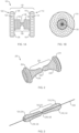
FIGS. 1A-1B provide side (FIG. 1A ) and front (FIG. 1B ) perspective views of a medical device, according to one embodiment of the present disclosure. -
FIG. 2 provides a perspective view of a medical device, according to one embodiment of the present disclosure. -
FIG. 3 provides a perspective view of a medical device, according to one embodiment of the present disclosure. -
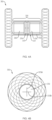
FIGS. 4A-4B provide side (FIG. 4A ) and front (FIG. 4B ) perspective views of a medical device, according to one embodiment of the present disclosure. -
FIGS. 5A-5D provide perspective views of a medical device, according to one embodiment of the present disclosure. -
FIGS. 6A-6B provide side (FIGS. 6A ) and front (FIG. 6B ) perspective views of a medical device, according to one embodiment of the present disclosure. -
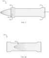
FIG. 7 provides a side perspective view of a medical device, according to one embodiment of the present disclosure. -
FIGS. 8A-8C provide side perspective views of a medical device, according to one embodiment of the present invention. -
FIGS. 9A-9B provide side perspective views of a medical device, extending through a medical device according to one embodiment of the present disclosure. - The present disclosure is not limited to the particular embodiments described. The terminology used herein is for the purpose of describing particular embodiments only, and is not intended to be limiting beyond the scope of the appended claims. Unless otherwise defined, all technical terms used herein have the same meaning as commonly understood by one of ordinary skill in the art to which the disclosure belongs.
- Although embodiments of the present disclosure are described with specific reference to medical devices (e.g., anastomotic devices, drainage stents, etc.) and systems to establish and/or maintain a controlled periodic or intermittent flow or access passage from or between the stomach or duodenal wall into the peritoneal cavity, it should be appreciated that such medical devices may be used in a variety of medical procedures, including natural orifice transluminal endoscopic surgery (NOTES) procedures, (e.g., external biliary drain conversion, enteroenterostomy, gastrojejumostomy, gastroduodenostomy and gastroileostomy, transcolonic procedures, transgastric procedures, transtracheal procedures, transvaginal procedures, cholelithiasis procedures, choledocholiathiasis procedures, etc.) to establish and/or maintain a controlled periodic or intermittent flow or access passage from or between a variety of body organs, lumens, ducts, vessels, fistulas, cysts and/or spaces (e.g., the dermis, stomach, duodenum, jejunum, small intestine, gallbladder, kidneys, pancreas, biliary / pancreatic trees, bladder, ureter, abscesses, walled-off pancreatic necrosis (WOPN), bile ducts, etc.). The devices can be inserted via different access points and approaches, e.g., percutaneously, endoscopically, laparoscopically or some combination thereof. The medical devices disclosed herein are self-expanding, but in other embodiments the medical device may be expandable by other means, including, e.g., a balloon catheter. Moreover, such medical devices are not limited to drainage, but may facilitate controlled access to organs, vessels or body lumens for other purposes, such as delivery of therapeutic agents and/or creating a path to divert or bypass fluids or solids from one location to another, removing obstructions and/or non-invasive or minimally invasive manipulation of tissues.
- As used herein, the singular forms "a," "an," and "the" are intended to include the plural forms as well, unless the context clearly indicates otherwise. It will be further understood that the terms "comprises" and/or "comprising," or "includes" and/or "including" when used herein, specify the presence of stated features, regions, steps, elements and/or components, but do not preclude the presence or addition of one or more other features, regions, integers, steps, operations, elements, components and/or groups thereof.
- As used herein, the term "distal" refers to the end farthest away from the medical professional when introducing a device into a patient, while the term "proximal" refers to the end closest to the medical professional when introducing a device into a patient.
- In one embodiment, the present disclosure relates to a medical device (e.g., anastomotic device, drainage stent, etc.) which may allow an efficient mechanism for controlled periodic access to a body lumen or organ to facilitate direct endoscopic delivery of Advanced Therapy Medicinal Products (ATMP's), e.g., immune check-point inhibitors, therapeutic agents, drugs, cellular therapy solutions, etc., for maximal therapeutic effect and minimal patient discomfort. For example, a medical device of the present disclosure may support controlled repeated/intermittent endoscopic delivery of immune boosting therapeutic fluids through the stomach or duodenal wall into a body cavity comprising or adjacent to a diseased organ or tissue.
- Referring to
FIG. 1A , in one embodiment, amedical device 100 of the present disclosure may include an elongatetubular body 110 forming a lumen and comprising aproximal portion 112, adistal portion 122, a length and a diameter. The elongatetubular body 110 may include an unexpanded configuration (e.g., constrained, undeployed or delivery configuration; not shown), and an expanded configuration (e.g., unconstrained, delivered or deployed configuration) where theproximal portion 112 radially expands into aproximal retention member 114, and thedistal portion 122 radially expands into adistal retention member 124, leaving acylindrical saddle region 130 extending therebetween. A diameter of thecylindrical saddle region 130 may be greater than a diameter of the elongatetubular body 110 in the unexpanded configuration. The proximal anddistal retention members tubular body 110 to definerespective surfaces cylindrical saddle region 130 may include a constricted or narrowed portion 138 (e.g., valve) disposed between larger diameter first andsecond end portions constricted portion 138 may be configured to move between a first diameter (e.g., closed) configuration which limits or prevents the flow of fluids and/or debris therethrough, and a second diameter (e.g., open) configuration larger than the first diameter, which provides an open flow or access passage therethrough. For example, as explained in further detail below, theconstricted portion 138 may be configured to move from the first diameter configuration to the second diameter configuration in response to a threshold level of force applied to the constricted portion, e.g., as exerted by a medical device advanced through thecylindrical saddle region 130. Themedical device 100 may comprise one or more woven, braided and/or knitted filaments, e.g., shape memory materials, which may allow theconstricted portion 138 to return to the first diameter configuration upon withdrawal/removal of the medical device from within thecylindrical saddle region 130. -
FIG. 1B provides a front perspective view of themedical device 100, with theconstricted portion 138 in the first diameter configuration such that substantially no opening or access passage extends through the cylindrical saddle region. In various embodiments, themedical device 100 of the present disclosure is not limited to the configuration depicted inFIG. 1A , but may include a variety of different configurations and/or dimensions. For example, referring toFIG. 2 , in one embodiment, amedical device 200 of the present disclosure may include proximal anddistal retention members cylindrical saddle region 230 with first andsecond end portions 234, 236 that are tapered in diameter toward the center of the cylindrical saddle region and disposed on either side of theconstricted portion 238.FIG. 3 provides a perspective view of themedical device guidewire 250 in a partially deployed configuration. Although thecylindrical saddle region medical devices medical devices - Referring to
FIGS. 4A-4B , in one embodiment, amedical device 300 of the present disclosure may include the identical, or similar, configuration and elements asmedical devices cylindrical saddle region 330 includes a constant inner and outer diameter. In one embodiment, themedical device 300 may include aplug 331 disposed within thecylindrical saddle region 330. Theplug 331 may include first andsecond membranes housing 332 between first andsecond washers second membranes more slits 333a/b, 334a/b (FIG. 5A ) configured to move between a first (e.g., closed) configuration which limits or prevents the flow of fluids and/or debris therethrough, and a second (e.g., open) configuration which provides an open flow or access passage therethrough. For example, theslits 333a/b, 334a/b may be configured to move from the first to second configuration in response to a threshold level of force applied to the first andsecond membranes second membranes slits 333a/b, 334a/b to return to the first configuration upon withdrawal/removal of the medical device from within theplug 331. -
FIG. 4B provides a front perspective view of themedical device 300, with theslits 333a/b of thefirst membrane 333 in the first configuration such that substantially no opening or access passage extends through the cylindrical saddle region. Although themembranes plug 331 may include any number of membranes (e.g., a single membrane, three or more membranes, etc.) with a variety of sizes, shapes, configurations and/or thicknesses. Similarly, although theslits 333a/b, 334a/b formed within themembranes - Referring to
FIGS. 5A-5D , in one embodiment, theplug 331 may be assembled by positioning the first andsecond membranes sheath 332 between the first andsecond washers second washers FIG. 5B , each of the first andsecond membranes second washers sheath 332. Referring toFIG. 5C , in one embodiment, thesheath 332 may include a polymeric or plastic material configured to collapse or shrink (e.g., heat shrink material) upon exposure to an elevated temperature (e.g., 100°C-150°C) to lock or secure the position/orientation of the first andsecond membranes second washers plug 331 may include an outer diameter d1 (FIG. 5C ) which is substantially equal to, or slightly greater than, an inner diameter d2 (FIG. 4A ) of thecylindrical saddle region 330, such that thesheath 332 may form a friction, compression or interference fit with a portion of the inner wall of thecylindrical saddle region 330. In addition, or alternatively, thesheath 332 may be coated or impregnated with a hydrogel material which expands or swells upon contact with aqueous fluids (e.g., body fluids) to firmly engage the outer surface of thesheath 332 with the inner wall of thecylindrical saddle region 330. - Although the
plug 331 is depicted as a component ofmedical device 300 of the present disclosure, in various embodiments, the plug may be incorporated into any of themedical devices - Referring to
FIG. 6A , in one embodiment, amedical device 400 of the present disclosure may include an elongatetubular body 410 forming a lumen and comprising aproximal portion 412, adistal portion 422, a length and a diameter. The elongatetubular body 410 may include an unexpanded configuration (e.g., constrained, undeployed or delivery configuration; not shown), and an expanded configuration (e.g., unconstrained, delivered or deployed configuration) where theproximal portion 412 radially expands into aproximal retention member 414, and thedistal portion 422 radially expands into adistal retention member 424, leaving acylindrical saddle region 430 with a constant inner and outer diameter extending therebetween. A diameter of thecylindrical saddle region 430 may be greater than a diameter of the elongatetubular body 410 in the unexpanded configuration. The proximal anddistal retention members tubular body 410 to definerespective surfaces nose cone 432 comprising a plurality of flexible overlapping loops may extend distally beyond thedistal retention member 424. Each of the loops may include a membrane, covering or coating on an inner and/or outer surface thereof. In one embodiment, thenose cone 432 may be integrally formed with the woven, braided and/or knitted filaments, which comprise the elongatetubular body 410. In addition, or alternatively, aproximal end 436 of thenose cone 432 may be affixed to the distal retention member using a suitable glue, adhesive, resin, solder or other bonding techniques, as are commonly known in the art. In one embodiment, each of the plurality of flexible overlapping loops may include a curled or tapered shape to form anose cone 432 configured to move between a first diameter (e.g., closed) configuration which limits or prevents the flow of fluids into the cylindrical saddle region, and a second diameter (e.g., open) configuration larger than the first diameter configuration, which provides an open flow or access passage therethrough. For example, thenose cone 432 may be configured to move from the first to second diameter configurations in response to a threshold level of force applied to the nose cone, e.g., as exerted by a medical device advanced through the proximal retention member, cylindrical saddle region and distal retention member. The plurality of loops, e.g., comprised of shape memory fibers or filaments, may allow thenose cone 432 to return to the first diameter configuration upon withdrawal/removal of the medical device from within the cylindrical saddle region.FIG. 6B provides a front perspective view of themedical device 400, with the distal ends of each of the plurality of flexible overlapping loops in the first configuration (e.g., in contact with each other) such that substantially no opening or access passage extends through thenose cone 432 into the cylindrical saddle region. - In various embodiments, the surfaces of the proximal retention members, e.g., of
medical devices - In one embodiment, a medical device of the present disclosure may be configured to be disposed within an open interior passage of another medical device (e.g., a conventional drainage stent), prior to the other medical device being deployed, or after the other medical has been deployed, in order to provide periodic flow and/or access therethrough. For example, referring to
FIG. 7 , in one embodiment, amedical device 500 of the present disclosure may include the identical, or similar, configuration and elements asmedical device 400, with the exception that the proximal anddistal retention members flat surfaces medical device 500 is deployed, as discussed below. - Referring to
FIG. 8A , in one embodiment of the invention, amedical device 600 of the present disclosure may include the identical, or similar, configuration and elements asmedical device 500, with the exception that the nose cone is replaced with aninternal cone 632 disposed within the cylindrical saddle region. The internal cone may include a portion that tapers in diameter toward the distal retention member. According to the invention, theinternal cone 632 includes a plurality loops, e.g., comprised of shape memory fibers or filaments, integrally formed with the filament braid comprising the cylindrical saddle region. As above, each of the loops may include a membrane, covering or coating on an inner and/or outer surface thereof. In addition, or alternatively, an outer surface of theinternal cone 632 may be affixed within the cylindrical saddle region using a suitable glue, adhesive, resin, solder or other bonding techniques, as are commonly known in the art. As above, in one embodiment, each of the plurality of flexible overlapping loops may include a curled or tapered shape to form a distally-facinginternal cone 632 configured to move between a first diameter (e.g., closed) configuration which limits or prevents the flow of fluids and/or debris through the cylindrical saddle region, and a second diameter (e.g., open) configuration larger than the first diameter configuration, which provides an open flow or access passage therethrough. For example, theinternal cone 632 may be configured to move from the first to second diameter configuration in response to a threshold level of force applied to the internal cone, e.g., as exerted by a medical device advanced through the proximal retention member, cylindrical saddle region and distal retention member. Shape memory fibers or filaments, which may comprise the plurality of flexible loops, allow theinternal cone 632 to return to the first diameter configuration upon withdrawal/removal of the medical device from within the cylindrical saddle region. Although depicted inFIG. 8A in a body with a "land flare" configuration, as described above with reference toFIG. 7 , an internal cone, integrally formed with or affixed to a body, may be utilized in the body with any of the various flange configurations described herein. - Referring to
FIGS. 8B-8C , in various embodiments, themedical device 600 may be disposed within a previously deployedconventional drainage stent 700 to convert the open interior passage into a periodic flow or access passage, as discussed above. Therespective surfaces distal retention members medical device 700 to prevent migration of themedical device 600 therein. AlthoughFIGS. 8B and 8C depictmedical device 600 disposed within the lumen (FIG. 8B ) or cylindrical saddle region (FIG. 8C ) of a conventional self-expandingdrainage stent 700, in various embodiments themedical device 500 ofFIG. 7 may also be disposed within a previously deployed conventional drainage stent. - Referring to
FIG. 9A , in one embodiment, a user may advance a medical tool 440 (e.g., drainage catheter, infusion catheter, micro-infusion catheter, etc.) through a previously implantedmedical device 400, e.g., under endoscopic guidance, and with or without the aid of a previously placed guidewire for the medical tool. In various embodiments, themedical tool 440 may deliver a therapeutic agent into a cavity or space surrounding or adjacent to a diseased tissue or organ. In addition to delivering an effective dose of the therapeutic agent directly within the target body lumen for maximum beneficial effect, the ability of themedical device 400 with, e.g., nose cone, to move between the closed and open configurations, may allow a prolonged regimen (e.g., weeks, months or years) of one or more therapeutic agents to be administered without causing undue discomfort to the patient. In addition, or alternatively, themedical tool 440 may be configured to lavage and/or suction fluid and/or debris from within an abscess or pseudocyst. Referring toFIG. 9B , in another embodiment, a drainage device 450 (e.g., pigtail stent, etc.) may be positioned within a previously implantedmedical device 400, e.g., under endoscopic guidance to provide an open flow path therethrough. Once the medical tool (FIG. 9A ) or drainage device (FIG. 9B ) is proximally withdrawn from within themedical device 400, the nose cone may return to the first (e.g., closed) position to limit and/or prevent flow therethrough. AlthoughFIGS. 9A-9B depict amedical tool 440 ordrainage device 450 introduced through a previously implantedmedical device 400, in various embodiments these (and other) medical tools and drainage devices may be introduced through any of themedical devices - In use and by way of example, a
medical device - In various embodiments, the tissue penetrating element may be advanced over a guidewire previously advanced through the first and second body lumens such that a distal end of the guidewire is disposed within the second body lumen. Alternatively, in the method above, a separate instrument with a sharpened distal tip may be advanced along the path above and into the second body lumen to create a path. A guidewire may be put in place, or left in place if used to guide the separate instrument, and the separate instrument withdrawn over the guidewire.
- A
medical device - The distal portion of the
medical device medical device - Alternatively, a
medical device medical device medical device - The elongate tubular body of any of the
medical devices FIGS. 1A-9B may be formed of one or more braided filaments (e.g., nitinol wire, etc.). The proximal retention member, distal retention member, cylindrical saddle region, nose cone and/or internal cone may further include a membrane, covering or coating on an inner and/or outer surface thereof to define a contiguous open interior passage configured for controlled flow (e.g., body fluids, materials, and the like) and/or access therethrough. The coating may comprise a variety of non-degradable and biocompatible polymeric materials (e.g., upon exposure to bodily fluids such as bile), including, for example, silicones, rubbers, polyethylenes, PVDF, Chronoflex® and thermoplastic elastomers, such that the coating conforms to the medical device in the unexpanded and expanded configurations. - The proximal and distal retention members of any of the
medical devices FIGS. 1A-9B may include various configurations, such that one or more of the retention members extend radially at an angle from the longitudinal axis of the elongate tubular body that is not necessarily perpendicular to the elongate tubular body and/or the surfaces are not necessarily planar. In various embodiments, the angle of the retention members relative to the circumference and longitudinal axis of the elongate tubular body may assume other degrees (e.g., 30, 45, 60, 75 degrees, etc.) or may change degrees along the length of the retention members creating inflection points in the retention members. For example, one or both of the proximal and distal retention members may extend outward towards an end of the elongate tubular body, back towards a center portion of the elongate tubular body, or change directions in some combination of both. - For example, one or both of the proximal and distal retention members may flare away from a longitudinal axis of the cylindrical saddle region into flange configurations on opposite ends of the cylindrical saddle region when in the expanded configuration. Each flange configuration may include at least first and second points of inflection that may define first and second segments of the flange. The first segment may extend from the first inflection point toward a center plane perpendicular to the longitudinal axis of the tubular body, and the second segment may extend from the first inflection point away from the center plane. An angle of the first inflection point defined by the first segment and the cylindrical saddle region may be at least as great as an opposing angle of the second inflection point defined by the first segment and the second segment.
- As another example, each flange may include at least first and second points of inflection that define first and second segments of the flange, wherein the second points of inflection may be further spaced radially from the longitudinal axis than the first points of inflection, and the second points of inflection may be closer than the first points of inflection to a center plane along the longitudinal axis. The flanges on opposite ends of the cylindrical saddle region may touch planes that are parallel to the longitudinal axis, at least one plane each above and below the longitudinal axis, at at least two separate points along the parallel planes.
- As yet a further example, each flange configuration may include at least first and second points of inflection that define first and second segments of the flange. The first segment may extend from the first inflection point toward a center plane perpendicular to the longitudinal axis of the tubular body, and the second segment may extend from the second inflection point away from the center plane. The intersection of the cylindrical saddle region and the first segments may define the first inflection points, and the intersection of the first segments and second segments may define second inflection points. An angle of the first inflection points may be 90 degrees or less, and an opposing angle of the second inflection points may be 90 degrees or less.
- In various embodiments, one or both of the proximal and distal retention members may include an outer diameter d1 that is greater than an outer diameter d2 of the cylindrical saddle region. For example, outer diameter d1 may be as much as 75%-100% greater than an outer diameter d2 of the cylindrical saddle region. By way of non-limiting example, outer diameter d1 may be approximately 7.0 mm to approximately 30 mm, and outer diameter d2 may be approximately 3.0 mm to approximately 15.0 mm. In various embodiments, the size (e.g., diameter) of the opening formed between the first and second body lumens may be increased or decreased by increasing or decreasing the size (e.g., width) of the proximal and distal retention members (e.g., increasing or decreasing the surface area of the tissue layers compressed between the proximal and distal retention members). In addition, or alternatively, a length of the elongate tubular body in the expanded configuration may be foreshortened, e.g., at least 40% shorter than a length of the elongate tubular body when in the unexpanded configuration.
- Various embodiments, e.g., the
medical devices - In various embodiments, the direction of the nose cone or internal cone may be reversed, e.g., such that a portion of the nose cone or internal cone tapers in diameter toward the proximal retention member, to prevent or minimize the flow or fluid and/or debris from the first body lumen into the second body lumen (e.g., retrograde flow or reflux). In addition, or alternatively, in various embodiments, any of the medical devices disclosed herein may positioned within a patient such that the proximal retention member is placed in contact with the tissue wall of the second body lumen, and the distal retention member is placed in contact with the tissue wall of first body lumen to effectuate the same purpose to prevent or minimize the flow or fluid and/or debris from the first body lumen into the second body lumen (e.g., retrograde flow or reflux).
- In various embodiments, any of the woven, braided and/or knitted filaments, which comprise the elongate tubular body, nose cone and/or internal cone may include a variety of different cross-sectional shapes (e.g., oval, round, flat, square, etc.) and may be formed from metals and/or polymers, including shape memory metals and polymers. The woven, braided and/or knitted filament may further include a single filament woven upon itself, or multiple filaments woven together.
Claims (14)
- A medical device (600), comprisingan elongate tubular body comprising a proximal portion, a distal portion, and a length therebetween, the elongate tubular body defining a lumen along the length;the elongate tubular body having an unexpanded configuration, and an expanded configuration wherein the proximal portion expands into a proximal retention member, the distal portion expands into a distal retention member, and a cylindrical saddle region extends therebetween;wherein the cylindrical saddle region includes an internal cone (632) configured to move between a first diameter configuration which limits or prevents the flow of fluids and/or debris through the cylindrical saddle region, and a second diameter configuration larger than the first diameter configuration, which provides an open flow or access passage therethrough; andcharacterised in thatthe internal cone (632) comprises a plurality of overlapping flexible filament loops.
- The medical device ( 600) of claim 1, wherein the internal cone (632) is configured to move from the first diameter configuration to the second diameter configuration in response to a threshold force applied to the internal cone (632).
- The medical device ( 600) of any of claims 1-2, wherein the internal cone (632) is positioned at an approximate midpoint of the cylindrical saddle region.
- The medical device ( 600) of any of claims 1-3, wherein the internal cone (632) includes a portion that tapers in diameter toward the distal retention member.
- The medical device ( 600) of any of claims 1-4, wherein the distal retention member, proximal retention member, cylindrical saddle region and internal cone (632) are covered.
- The medical device ( 600) of any of claims 1-5, wherein the elongate tubular body is formed of one or more braided filaments
- The medical device ( 600) of any of claims 1-6, wherein the internal cone (632) is attached to an inner wall of the cylindrical saddle region.
- The medical device ( 600) of claim 6, wherein the internal cone (632) is integrally formed with the one or more braided filaments of the elongate tubular body.
- The medical device ( 600) of any of claims 1-8, wherein a surface of the proximal retention member is configured to contact an inner surface of a tissue wall of a first body lumen, and a surface of the distal retention member is configured to contact an inner surface of a tissue wall of a second body lumen.
- The medical device ( 600) of claim 9, wherein the proximal and distal retention members are configured to appose the tissue walls of the first and second body lumens between the proximal and distal retention members along the cylindrical saddle region.
- The medical device ( 600) of any of claims 1-8, wherein the medical device ( 600) comprises a first stent, and a surface (616; 626) of the proximal and distal retention members is configured to contact an inner surface of an open interior passage of a second stent (700).
- The medical device ( 600) of any of claims 1-11, wherein the proximal retention member includes a single-walled flange structure, and the distal retention member includes a single-walled flange structure.
- The medical device ( 600) of claim 12, wherein the single-walled flange structures extend radially from the cylindrical saddle region.
- The medical device ( 600) of any of claims 1-13, wherein a diameter of the proximal and distal retention members is greater than a diameter of the cylindrical saddle region.
Applications Claiming Priority (2)
| Application Number | Priority Date | Filing Date | Title |
|---|---|---|---|
| US201762567679P | 2017-10-03 | 2017-10-03 | |
| PCT/US2018/053839 WO2019070623A1 (en) | 2017-10-03 | 2018-10-02 | Flow control stent |
Publications (2)
| Publication Number | Publication Date |
|---|---|
| EP3634259A1 EP3634259A1 (en) | 2020-04-15 |
| EP3634259B1 true EP3634259B1 (en) | 2024-02-14 |
Family
ID=63963516
Family Applications (1)
| Application Number | Title | Priority Date | Filing Date |
|---|---|---|---|
| EP18792722.3A Active EP3634259B1 (en) | 2017-10-03 | 2018-10-02 | Flow control stent |
Country Status (7)
| Country | Link |
|---|---|
| US (3) | US11998707B2 (en) |
| EP (1) | EP3634259B1 (en) |
| JP (3) | JP6926318B2 (en) |
| CN (1) | CN111182840A (en) |
| AU (1) | AU2018346851B2 (en) |
| CA (1) | CA3072236C (en) |
| WO (1) | WO2019070623A1 (en) |
Families Citing this family (25)
| Publication number | Priority date | Publication date | Assignee | Title |
|---|---|---|---|---|
| JP7131742B2 (en) | 2016-09-29 | 2022-09-06 | メリット・メディカル・システムズ・インコーポレイテッド | A flexible member for receiving a vascular prosthesis and assisting in its deployment |
| EP4467111A3 (en) | 2017-03-15 | 2025-03-05 | Merit Medical Systems, Inc. | Transluminal stents |
| CN109758204A (en) * | 2018-11-02 | 2019-05-17 | 江苏省人民医院 | A kind of esophago-tracheal fistula plug rack and its device for posting and its method for posting |
| CN114025716B (en) | 2019-02-07 | 2025-08-12 | Nxt生物医疗有限责任公司 | Rivet shunt and deployment method |
| CN117838209A (en) * | 2019-05-03 | 2024-04-09 | 瑞克偌斯有氧运动公司 | Transseptal cardiac occluder device |
| RU195383U9 (en) * | 2019-07-31 | 2020-03-27 | Государственное бюджетное учреждение здравоохранения города Москвы "Научно-исследовательский институт скорой помощи им. Н.В. Склифосовского Департамента здравоохранения города Москвы" (ГБУЗ "НИИ СП ИМ. Н.В. СКЛИФОСОВСКОГО ДЗМ") | STENT FOR ENDOSCOPIC TREATMENT OF Pseudocyst of the pancreas |
| CN110522485B (en) * | 2019-08-27 | 2020-12-11 | 浙江大学 | A degradable intestinal complete bypass stent |
| KR102724251B1 (en) * | 2019-11-18 | 2024-10-30 | 보스톤 싸이엔티픽 싸이메드 인코포레이티드 | Stents with improved anti-migratory properties |
| KR102789924B1 (en) * | 2020-04-06 | 2025-04-01 | 보스톤 싸이엔티픽 싸이메드 인코포레이티드 | High maintenance drainage device |
| EP4185239A4 (en) | 2020-07-24 | 2024-08-07 | Merit Medical Systems, Inc. | ESOPHAGEAL STENT PROSTHESES AND RELATED METHODS |
| WO2022056381A1 (en) * | 2020-09-14 | 2022-03-17 | Boston Scientific Scimed, Inc. | Stents and methods for use and manufacture of stents with improved retention members |
| CN116456941A (en) * | 2020-09-24 | 2023-07-18 | 波士顿科学国际有限公司 | Stent devices and methods for increasing patency of body openings |
| WO2022066566A1 (en) * | 2020-09-25 | 2022-03-31 | Boston Scientific Scimed, Inc. | Adjustable lumen apposing stent |
| WO2022093710A1 (en) | 2020-10-26 | 2022-05-05 | Merit Medical Systems, Inc. | Esophageal stents with helical thread |
| US12582391B2 (en) | 2020-11-02 | 2026-03-24 | Recross Cardio Inc. | Interseptal occluder device |
| US20220192854A1 (en) * | 2020-12-22 | 2022-06-23 | Boston Scientific Scimed, Inc. | Pyloric device |
| CN112773440A (en) * | 2021-02-05 | 2021-05-11 | 南微医学科技股份有限公司 | Anastomosis device |
| KR102930660B1 (en) * | 2021-05-19 | 2026-02-24 | 보스톤 싸이엔티픽 싸이메드 인코포레이티드 | System for adjusting passage through implantable device |
| US12588910B1 (en) | 2021-11-08 | 2026-03-31 | VahatiCor, Inc. | Vascular flow restriction devices and related systems and methods |
| JP7824424B2 (en) * | 2022-02-08 | 2026-03-04 | ボストン サイエンティフィック サイムド,インコーポレイテッド | Devices, systems and methods for engageable stents |
| JP7732919B2 (en) * | 2022-02-15 | 2025-09-02 | Sbカワスミ株式会社 | Liquid Delivery Device |
| AU2024279937A1 (en) * | 2023-05-31 | 2025-12-11 | VS3 Medical, Inc. | Intravascular delivery systems and devices |
| US20250213345A1 (en) * | 2023-12-19 | 2025-07-03 | Boston Scientific Scimed, Inc. | Stent with features to reduce food impaction |
| CN118614978B (en) * | 2024-06-28 | 2025-02-14 | 中山大学附属第一医院 | A degradable biliary anastomosis device and its use method |
| CN119655935A (en) * | 2025-02-10 | 2025-03-21 | 上海市东方医院(同济大学附属东方医院) | Digestive tract sheath stent, stent system and use method |
Family Cites Families (22)
| Publication number | Priority date | Publication date | Assignee | Title |
|---|---|---|---|---|
| US5855601A (en) * | 1996-06-21 | 1999-01-05 | The Trustees Of Columbia University In The City Of New York | Artificial heart valve and method and device for implanting the same |
| US6641610B2 (en) | 1998-09-10 | 2003-11-04 | Percardia, Inc. | Valve designs for left ventricular conduits |
| KR100786028B1 (en) * | 2000-02-03 | 2007-12-17 | 쿡 인코포레이티드 | Implantable Vascular Device |
| US6494909B2 (en) * | 2000-12-01 | 2002-12-17 | Prodesco, Inc. | Endovascular valve |
| JP4398244B2 (en) | 2001-10-04 | 2010-01-13 | ネオヴァスク メディカル リミテッド | Flow reduction implant |
| US6790237B2 (en) * | 2001-10-09 | 2004-09-14 | Scimed Life Systems, Inc. | Medical stent with a valve and related methods of manufacturing |
| US9265605B2 (en) * | 2005-10-14 | 2016-02-23 | Boston Scientific Scimed, Inc. | Bronchoscopic lung volume reduction valve |
| CA2664557C (en) * | 2006-11-07 | 2015-05-26 | Corvia Medical, Inc. | Devices and methods for the treatment of heart failure |
| US8454632B2 (en) | 2008-05-12 | 2013-06-04 | Xlumena, Inc. | Tissue anchor for securing tissue layers |
| US20100056978A1 (en) * | 2008-08-27 | 2010-03-04 | Lindsay Machan | Externally adjustable blood flow valve |
| US20100131049A1 (en) | 2008-11-24 | 2010-05-27 | Medtronic Vascular, Inc. | One-Way valve Prosthesis for Percutaneous Placement Within the Venous System |
| US8500775B2 (en) * | 2009-12-02 | 2013-08-06 | Surefire Medical, Inc. | Protection device and method against embolization agent reflux |
| WO2012044453A1 (en) * | 2010-09-30 | 2012-04-05 | Cook Medical Technologies Llc | Soft crowns |
| EP3888602A1 (en) * | 2011-12-19 | 2021-10-06 | Coloplast A/S | A luminal prosthesis and a gastrointestinal implant device |
| WO2013173045A1 (en) | 2012-05-17 | 2013-11-21 | Xlumena, Inc. | Methods and devices for access across adjacent tissue layers |
| US20140031951A1 (en) * | 2012-07-27 | 2014-01-30 | Cook Medical Technologies Llc | Two-Way Valve |
| EP3669798B1 (en) * | 2013-02-21 | 2024-04-17 | Boston Scientific Scimed Inc. | Devices for forming an anastomosis |
| JP2015039515A (en) * | 2013-08-22 | 2015-03-02 | 独立行政法人国立循環器病研究センター | Artificial valve, base material for forming artificial valve, and method for producing artificial valve |
| US20170072173A1 (en) | 2015-09-13 | 2017-03-16 | Treus Legacy Partners, Llc | Inflatable translumenal shunts and methods and devices for delivery |
| US10531866B2 (en) | 2016-02-16 | 2020-01-14 | Cardiovalve Ltd. | Techniques for providing a replacement valve and transseptal communication |
| US10456237B2 (en) | 2016-03-07 | 2019-10-29 | Boston Scientific Scimed, Inc. | Esophageal stent including a valve member |
| WO2017154025A2 (en) | 2016-03-11 | 2017-09-14 | Hemant Deshmukh | A low profile, self-expanding, blood flow resisting device. |
-
2018
- 2018-10-02 WO PCT/US2018/053839 patent/WO2019070623A1/en not_active Ceased
- 2018-10-02 US US16/149,234 patent/US11998707B2/en active Active
- 2018-10-02 JP JP2020505442A patent/JP6926318B2/en active Active
- 2018-10-02 EP EP18792722.3A patent/EP3634259B1/en active Active
- 2018-10-02 CN CN201880065022.2A patent/CN111182840A/en active Pending
- 2018-10-02 CA CA3072236A patent/CA3072236C/en active Active
- 2018-10-02 AU AU2018346851A patent/AU2018346851B2/en active Active
-
2021
- 2021-08-04 JP JP2021127941A patent/JP7258966B2/en active Active
-
2023
- 2023-04-05 JP JP2023061195A patent/JP7416996B2/en active Active
-
2024
- 2024-04-30 US US18/650,803 patent/US12329921B2/en active Active
-
2025
- 2025-05-23 US US19/217,473 patent/US20250281727A1/en active Pending
Also Published As
| Publication number | Publication date |
|---|---|
| WO2019070623A1 (en) | 2019-04-11 |
| AU2018346851B2 (en) | 2020-08-06 |
| JP7258966B2 (en) | 2023-04-17 |
| US12329921B2 (en) | 2025-06-17 |
| US20190099589A1 (en) | 2019-04-04 |
| JP2021180878A (en) | 2021-11-25 |
| CA3072236A1 (en) | 2019-04-11 |
| EP3634259A1 (en) | 2020-04-15 |
| AU2018346851A1 (en) | 2020-01-30 |
| JP6926318B2 (en) | 2021-08-25 |
| US20240277982A1 (en) | 2024-08-22 |
| JP2023082183A (en) | 2023-06-13 |
| JP7416996B2 (en) | 2024-01-17 |
| CA3072236C (en) | 2023-09-26 |
| CN111182840A (en) | 2020-05-19 |
| US20250281727A1 (en) | 2025-09-11 |
| US11998707B2 (en) | 2024-06-04 |
| JP2020529884A (en) | 2020-10-15 |
Similar Documents
| Publication | Publication Date | Title |
|---|---|---|
| US12329921B2 (en) | Flow control stent | |
| US12490985B2 (en) | Flow control valve | |
| AU2018244748B2 (en) | Stents with dual tissue-wall anchoring features | |
| AU2018289395B2 (en) | Systems for creating permanent drainage fistula | |
| ES2963925T3 (en) | Fenestration devices and systems | |
| EP3741325B1 (en) | Biliary stent |
Legal Events
| Date | Code | Title | Description |
|---|---|---|---|
| STAA | Information on the status of an ep patent application or granted ep patent |
Free format text: STATUS: UNKNOWN |
|
| STAA | Information on the status of an ep patent application or granted ep patent |
Free format text: STATUS: THE INTERNATIONAL PUBLICATION HAS BEEN MADE |
|
| PUAI | Public reference made under article 153(3) epc to a published international application that has entered the european phase |
Free format text: ORIGINAL CODE: 0009012 |
|
| STAA | Information on the status of an ep patent application or granted ep patent |
Free format text: STATUS: REQUEST FOR EXAMINATION WAS MADE |
|
| 17P | Request for examination filed |
Effective date: 20200109 |
|
| AK | Designated contracting states |
Kind code of ref document: A1 Designated state(s): AL AT BE BG CH CY CZ DE DK EE ES FI FR GB GR HR HU IE IS IT LI LT LU LV MC MK MT NL NO PL PT RO RS SE SI SK SM TR |
|
| AX | Request for extension of the european patent |
Extension state: BA ME |
|
| DAV | Request for validation of the european patent (deleted) | ||
| DAX | Request for extension of the european patent (deleted) | ||
| STAA | Information on the status of an ep patent application or granted ep patent |
Free format text: STATUS: EXAMINATION IS IN PROGRESS |
|
| 17Q | First examination report despatched |
Effective date: 20220608 |
|
| RIC1 | Information provided on ipc code assigned before grant |
Ipc: A61B 17/11 20060101ALI20230728BHEP Ipc: A61F 2/04 20130101ALI20230728BHEP Ipc: A61M 27/00 20060101ALI20230728BHEP Ipc: A61B 17/12 20060101AFI20230728BHEP |
|
| GRAP | Despatch of communication of intention to grant a patent |
Free format text: ORIGINAL CODE: EPIDOSNIGR1 |
|
| STAA | Information on the status of an ep patent application or granted ep patent |
Free format text: STATUS: GRANT OF PATENT IS INTENDED |
|
| INTG | Intention to grant announced |
Effective date: 20230914 |
|
| GRAS | Grant fee paid |
Free format text: ORIGINAL CODE: EPIDOSNIGR3 |
|
| GRAA | (expected) grant |
Free format text: ORIGINAL CODE: 0009210 |
|
| STAA | Information on the status of an ep patent application or granted ep patent |
Free format text: STATUS: THE PATENT HAS BEEN GRANTED |
|
| AK | Designated contracting states |
Kind code of ref document: B1 Designated state(s): AL AT BE BG CH CY CZ DE DK EE ES FI FR GB GR HR HU IE IS IT LI LT LU LV MC MK MT NL NO PL PT RO RS SE SI SK SM TR |
|
| REG | Reference to a national code |
Ref country code: GB Ref legal event code: FG4D |
|
| REG | Reference to a national code |
Ref country code: CH Ref legal event code: EP |
|
| REG | Reference to a national code |
Ref country code: DE Ref legal event code: R096 Ref document number: 602018065247 Country of ref document: DE |
|
| REG | Reference to a national code |
Ref country code: IE Ref legal event code: FG4D |
|
| REG | Reference to a national code |
Ref country code: NL Ref legal event code: FP |
|
| REG | Reference to a national code |
Ref country code: LT Ref legal event code: MG9D |
|
| PG25 | Lapsed in a contracting state [announced via postgrant information from national office to epo] |
Ref country code: IS Free format text: LAPSE BECAUSE OF FAILURE TO SUBMIT A TRANSLATION OF THE DESCRIPTION OR TO PAY THE FEE WITHIN THE PRESCRIBED TIME-LIMIT Effective date: 20240614 |
|
| PG25 | Lapsed in a contracting state [announced via postgrant information from national office to epo] |
Ref country code: LT Free format text: LAPSE BECAUSE OF FAILURE TO SUBMIT A TRANSLATION OF THE DESCRIPTION OR TO PAY THE FEE WITHIN THE PRESCRIBED TIME-LIMIT Effective date: 20240214 |
|
| PG25 | Lapsed in a contracting state [announced via postgrant information from national office to epo] |
Ref country code: GR Free format text: LAPSE BECAUSE OF FAILURE TO SUBMIT A TRANSLATION OF THE DESCRIPTION OR TO PAY THE FEE WITHIN THE PRESCRIBED TIME-LIMIT Effective date: 20240515 |
|
| REG | Reference to a national code |
Ref country code: AT Ref legal event code: MK05 Ref document number: 1656358 Country of ref document: AT Kind code of ref document: T Effective date: 20240214 |
|
| PG25 | Lapsed in a contracting state [announced via postgrant information from national office to epo] |
Ref country code: HR Free format text: LAPSE BECAUSE OF FAILURE TO SUBMIT A TRANSLATION OF THE DESCRIPTION OR TO PAY THE FEE WITHIN THE PRESCRIBED TIME-LIMIT Effective date: 20240214 Ref country code: RS Free format text: LAPSE BECAUSE OF FAILURE TO SUBMIT A TRANSLATION OF THE DESCRIPTION OR TO PAY THE FEE WITHIN THE PRESCRIBED TIME-LIMIT Effective date: 20240514 |
|
| PG25 | Lapsed in a contracting state [announced via postgrant information from national office to epo] |
Ref country code: ES Free format text: LAPSE BECAUSE OF FAILURE TO SUBMIT A TRANSLATION OF THE DESCRIPTION OR TO PAY THE FEE WITHIN THE PRESCRIBED TIME-LIMIT Effective date: 20240214 |
|
| PG25 | Lapsed in a contracting state [announced via postgrant information from national office to epo] |
Ref country code: AT Free format text: LAPSE BECAUSE OF FAILURE TO SUBMIT A TRANSLATION OF THE DESCRIPTION OR TO PAY THE FEE WITHIN THE PRESCRIBED TIME-LIMIT Effective date: 20240214 |
|
| PG25 | Lapsed in a contracting state [announced via postgrant information from national office to epo] |
Ref country code: RS Free format text: LAPSE BECAUSE OF FAILURE TO SUBMIT A TRANSLATION OF THE DESCRIPTION OR TO PAY THE FEE WITHIN THE PRESCRIBED TIME-LIMIT Effective date: 20240514 Ref country code: NO Free format text: LAPSE BECAUSE OF FAILURE TO SUBMIT A TRANSLATION OF THE DESCRIPTION OR TO PAY THE FEE WITHIN THE PRESCRIBED TIME-LIMIT Effective date: 20240514 Ref country code: LT Free format text: LAPSE BECAUSE OF FAILURE TO SUBMIT A TRANSLATION OF THE DESCRIPTION OR TO PAY THE FEE WITHIN THE PRESCRIBED TIME-LIMIT Effective date: 20240214 Ref country code: IS Free format text: LAPSE BECAUSE OF FAILURE TO SUBMIT A TRANSLATION OF THE DESCRIPTION OR TO PAY THE FEE WITHIN THE PRESCRIBED TIME-LIMIT Effective date: 20240614 Ref country code: HR Free format text: LAPSE BECAUSE OF FAILURE TO SUBMIT A TRANSLATION OF THE DESCRIPTION OR TO PAY THE FEE WITHIN THE PRESCRIBED TIME-LIMIT Effective date: 20240214 Ref country code: GR Free format text: LAPSE BECAUSE OF FAILURE TO SUBMIT A TRANSLATION OF THE DESCRIPTION OR TO PAY THE FEE WITHIN THE PRESCRIBED TIME-LIMIT Effective date: 20240515 Ref country code: FI Free format text: LAPSE BECAUSE OF FAILURE TO SUBMIT A TRANSLATION OF THE DESCRIPTION OR TO PAY THE FEE WITHIN THE PRESCRIBED TIME-LIMIT Effective date: 20240214 Ref country code: ES Free format text: LAPSE BECAUSE OF FAILURE TO SUBMIT A TRANSLATION OF THE DESCRIPTION OR TO PAY THE FEE WITHIN THE PRESCRIBED TIME-LIMIT Effective date: 20240214 Ref country code: BG Free format text: LAPSE BECAUSE OF FAILURE TO SUBMIT A TRANSLATION OF THE DESCRIPTION OR TO PAY THE FEE WITHIN THE PRESCRIBED TIME-LIMIT Effective date: 20240214 Ref country code: AT Free format text: LAPSE BECAUSE OF FAILURE TO SUBMIT A TRANSLATION OF THE DESCRIPTION OR TO PAY THE FEE WITHIN THE PRESCRIBED TIME-LIMIT Effective date: 20240214 |
|
| PG25 | Lapsed in a contracting state [announced via postgrant information from national office to epo] |
Ref country code: PL Free format text: LAPSE BECAUSE OF FAILURE TO SUBMIT A TRANSLATION OF THE DESCRIPTION OR TO PAY THE FEE WITHIN THE PRESCRIBED TIME-LIMIT Effective date: 20240214 Ref country code: PT Free format text: LAPSE BECAUSE OF FAILURE TO SUBMIT A TRANSLATION OF THE DESCRIPTION OR TO PAY THE FEE WITHIN THE PRESCRIBED TIME-LIMIT Effective date: 20240614 |
|
| PG25 | Lapsed in a contracting state [announced via postgrant information from national office to epo] |
Ref country code: SE Free format text: LAPSE BECAUSE OF FAILURE TO SUBMIT A TRANSLATION OF THE DESCRIPTION OR TO PAY THE FEE WITHIN THE PRESCRIBED TIME-LIMIT Effective date: 20240214 Ref country code: PT Free format text: LAPSE BECAUSE OF FAILURE TO SUBMIT A TRANSLATION OF THE DESCRIPTION OR TO PAY THE FEE WITHIN THE PRESCRIBED TIME-LIMIT Effective date: 20240614 Ref country code: PL Free format text: LAPSE BECAUSE OF FAILURE TO SUBMIT A TRANSLATION OF THE DESCRIPTION OR TO PAY THE FEE WITHIN THE PRESCRIBED TIME-LIMIT Effective date: 20240214 Ref country code: LV Free format text: LAPSE BECAUSE OF FAILURE TO SUBMIT A TRANSLATION OF THE DESCRIPTION OR TO PAY THE FEE WITHIN THE PRESCRIBED TIME-LIMIT Effective date: 20240214 |
|
| PG25 | Lapsed in a contracting state [announced via postgrant information from national office to epo] |
Ref country code: DK Free format text: LAPSE BECAUSE OF FAILURE TO SUBMIT A TRANSLATION OF THE DESCRIPTION OR TO PAY THE FEE WITHIN THE PRESCRIBED TIME-LIMIT Effective date: 20240214 |
|
| PG25 | Lapsed in a contracting state [announced via postgrant information from national office to epo] |
Ref country code: SM Free format text: LAPSE BECAUSE OF FAILURE TO SUBMIT A TRANSLATION OF THE DESCRIPTION OR TO PAY THE FEE WITHIN THE PRESCRIBED TIME-LIMIT Effective date: 20240214 |
|
| PG25 | Lapsed in a contracting state [announced via postgrant information from national office to epo] |
Ref country code: CZ Free format text: LAPSE BECAUSE OF FAILURE TO SUBMIT A TRANSLATION OF THE DESCRIPTION OR TO PAY THE FEE WITHIN THE PRESCRIBED TIME-LIMIT Effective date: 20240214 Ref country code: EE Free format text: LAPSE BECAUSE OF FAILURE TO SUBMIT A TRANSLATION OF THE DESCRIPTION OR TO PAY THE FEE WITHIN THE PRESCRIBED TIME-LIMIT Effective date: 20240214 |
|
| PG25 | Lapsed in a contracting state [announced via postgrant information from national office to epo] |
Ref country code: SK Free format text: LAPSE BECAUSE OF FAILURE TO SUBMIT A TRANSLATION OF THE DESCRIPTION OR TO PAY THE FEE WITHIN THE PRESCRIBED TIME-LIMIT Effective date: 20240214 |
|
| PG25 | Lapsed in a contracting state [announced via postgrant information from national office to epo] |
Ref country code: SM Free format text: LAPSE BECAUSE OF FAILURE TO SUBMIT A TRANSLATION OF THE DESCRIPTION OR TO PAY THE FEE WITHIN THE PRESCRIBED TIME-LIMIT Effective date: 20240214 Ref country code: SK Free format text: LAPSE BECAUSE OF FAILURE TO SUBMIT A TRANSLATION OF THE DESCRIPTION OR TO PAY THE FEE WITHIN THE PRESCRIBED TIME-LIMIT Effective date: 20240214 Ref country code: RO Free format text: LAPSE BECAUSE OF FAILURE TO SUBMIT A TRANSLATION OF THE DESCRIPTION OR TO PAY THE FEE WITHIN THE PRESCRIBED TIME-LIMIT Effective date: 20240214 Ref country code: EE Free format text: LAPSE BECAUSE OF FAILURE TO SUBMIT A TRANSLATION OF THE DESCRIPTION OR TO PAY THE FEE WITHIN THE PRESCRIBED TIME-LIMIT Effective date: 20240214 Ref country code: DK Free format text: LAPSE BECAUSE OF FAILURE TO SUBMIT A TRANSLATION OF THE DESCRIPTION OR TO PAY THE FEE WITHIN THE PRESCRIBED TIME-LIMIT Effective date: 20240214 Ref country code: CZ Free format text: LAPSE BECAUSE OF FAILURE TO SUBMIT A TRANSLATION OF THE DESCRIPTION OR TO PAY THE FEE WITHIN THE PRESCRIBED TIME-LIMIT Effective date: 20240214 |
|
| REG | Reference to a national code |
Ref country code: DE Ref legal event code: R097 Ref document number: 602018065247 Country of ref document: DE |
|
| PG25 | Lapsed in a contracting state [announced via postgrant information from national office to epo] |
Ref country code: IT Free format text: LAPSE BECAUSE OF FAILURE TO SUBMIT A TRANSLATION OF THE DESCRIPTION OR TO PAY THE FEE WITHIN THE PRESCRIBED TIME-LIMIT Effective date: 20240214 |
|
| PLBE | No opposition filed within time limit |
Free format text: ORIGINAL CODE: 0009261 |
|
| STAA | Information on the status of an ep patent application or granted ep patent |
Free format text: STATUS: NO OPPOSITION FILED WITHIN TIME LIMIT |
|
| PG25 | Lapsed in a contracting state [announced via postgrant information from national office to epo] |
Ref country code: IT Free format text: LAPSE BECAUSE OF FAILURE TO SUBMIT A TRANSLATION OF THE DESCRIPTION OR TO PAY THE FEE WITHIN THE PRESCRIBED TIME-LIMIT Effective date: 20240214 |
|
| 26N | No opposition filed |
Effective date: 20241115 |
|
| PG25 | Lapsed in a contracting state [announced via postgrant information from national office to epo] |
Ref country code: SI Free format text: LAPSE BECAUSE OF FAILURE TO SUBMIT A TRANSLATION OF THE DESCRIPTION OR TO PAY THE FEE WITHIN THE PRESCRIBED TIME-LIMIT Effective date: 20240214 |
|
| REG | Reference to a national code |
Ref country code: CH Ref legal event code: PL |
|
| PG25 | Lapsed in a contracting state [announced via postgrant information from national office to epo] |
Ref country code: MC Free format text: LAPSE BECAUSE OF FAILURE TO SUBMIT A TRANSLATION OF THE DESCRIPTION OR TO PAY THE FEE WITHIN THE PRESCRIBED TIME-LIMIT Effective date: 20240214 |
|
| PG25 | Lapsed in a contracting state [announced via postgrant information from national office to epo] |
Ref country code: BE Free format text: LAPSE BECAUSE OF NON-PAYMENT OF DUE FEES Effective date: 20241031 Ref country code: LU Free format text: LAPSE BECAUSE OF NON-PAYMENT OF DUE FEES Effective date: 20241002 |
|
| PG25 | Lapsed in a contracting state [announced via postgrant information from national office to epo] |
Ref country code: FR Free format text: LAPSE BECAUSE OF NON-PAYMENT OF DUE FEES Effective date: 20241031 |
|
| PG25 | Lapsed in a contracting state [announced via postgrant information from national office to epo] |
Ref country code: CH Free format text: LAPSE BECAUSE OF NON-PAYMENT OF DUE FEES Effective date: 20241031 |
|
| REG | Reference to a national code |
Ref country code: BE Ref legal event code: MM Effective date: 20241031 |
|
| PGFP | Annual fee paid to national office [announced via postgrant information from national office to epo] |
Ref country code: NL Payment date: 20250923 Year of fee payment: 8 |
|
| PGFP | Annual fee paid to national office [announced via postgrant information from national office to epo] |
Ref country code: GB Payment date: 20250923 Year of fee payment: 8 |
|
| PGFP | Annual fee paid to national office [announced via postgrant information from national office to epo] |
Ref country code: IE Payment date: 20250925 Year of fee payment: 8 |
|
| PGFP | Annual fee paid to national office [announced via postgrant information from national office to epo] |
Ref country code: DE Payment date: 20250923 Year of fee payment: 8 |
|
| PG25 | Lapsed in a contracting state [announced via postgrant information from national office to epo] |
Ref country code: CY Free format text: LAPSE BECAUSE OF FAILURE TO SUBMIT A TRANSLATION OF THE DESCRIPTION OR TO PAY THE FEE WITHIN THE PRESCRIBED TIME-LIMIT; INVALID AB INITIO Effective date: 20181002 |
|
| PG25 | Lapsed in a contracting state [announced via postgrant information from national office to epo] |
Ref country code: HU Free format text: LAPSE BECAUSE OF FAILURE TO SUBMIT A TRANSLATION OF THE DESCRIPTION OR TO PAY THE FEE WITHIN THE PRESCRIBED TIME-LIMIT; INVALID AB INITIO Effective date: 20181002 |