EP3633846A1 - Rotational electric machine, drive control system of vehicle, and storage medium having program executed by or caused to be executed by control apparatus of rotational electric machine - Google Patents
Rotational electric machine, drive control system of vehicle, and storage medium having program executed by or caused to be executed by control apparatus of rotational electric machine Download PDFInfo
- Publication number
- EP3633846A1 EP3633846A1 EP19200874.6A EP19200874A EP3633846A1 EP 3633846 A1 EP3633846 A1 EP 3633846A1 EP 19200874 A EP19200874 A EP 19200874A EP 3633846 A1 EP3633846 A1 EP 3633846A1
- Authority
- EP
- European Patent Office
- Prior art keywords
- rotor
- electric machine
- direct current
- rotational
- motor characteristic
- Prior art date
- Legal status (The legal status is an assumption and is not a legal conclusion. Google has not performed a legal analysis and makes no representation as to the accuracy of the status listed.)
- Withdrawn
Links
Images





Classifications
-
- H—ELECTRICITY
- H02—GENERATION; CONVERSION OR DISTRIBUTION OF ELECTRIC POWER
- H02P—CONTROL OR REGULATION OF ELECTRIC MOTORS, ELECTRIC GENERATORS OR DYNAMO-ELECTRIC CONVERTERS; CONTROLLING TRANSFORMERS, REACTORS OR CHOKE COILS
- H02P27/00—Arrangements or methods for the control of AC motors characterised by the kind of supply voltage
- H02P27/04—Arrangements or methods for the control of AC motors characterised by the kind of supply voltage using variable-frequency supply voltage, e.g. inverter or converter supply voltage
- H02P27/06—Arrangements or methods for the control of AC motors characterised by the kind of supply voltage using variable-frequency supply voltage, e.g. inverter or converter supply voltage using DC to AC converters or inverters
- H02P27/08—Arrangements or methods for the control of AC motors characterised by the kind of supply voltage using variable-frequency supply voltage, e.g. inverter or converter supply voltage using DC to AC converters or inverters with pulse width modulation
-
- H—ELECTRICITY
- H02—GENERATION; CONVERSION OR DISTRIBUTION OF ELECTRIC POWER
- H02K—DYNAMO-ELECTRIC MACHINES
- H02K21/00—Synchronous motors having permanent magnets; Synchronous generators having permanent magnets
- H02K21/12—Synchronous motors having permanent magnets; Synchronous generators having permanent magnets with stationary armatures and rotating magnets
- H02K21/14—Synchronous motors having permanent magnets; Synchronous generators having permanent magnets with stationary armatures and rotating magnets with magnets rotating within the armatures
-
- H—ELECTRICITY
- H02—GENERATION; CONVERSION OR DISTRIBUTION OF ELECTRIC POWER
- H02P—CONTROL OR REGULATION OF ELECTRIC MOTORS, ELECTRIC GENERATORS OR DYNAMO-ELECTRIC CONVERTERS; CONTROLLING TRANSFORMERS, REACTORS OR CHOKE COILS
- H02P6/00—Arrangements for controlling synchronous motors or other dynamo-electric motors using electronic commutation dependent on the rotor position; Electronic commutators therefor
- H02P6/08—Arrangements for controlling the speed or torque of a single motor
-
- B—PERFORMING OPERATIONS; TRANSPORTING
- B60—VEHICLES IN GENERAL
- B60L—PROPULSION OF ELECTRICALLY-PROPELLED VEHICLES; SUPPLYING ELECTRIC POWER FOR AUXILIARY EQUIPMENT OF ELECTRICALLY-PROPELLED VEHICLES; ELECTRODYNAMIC BRAKE SYSTEMS FOR VEHICLES IN GENERAL; MAGNETIC SUSPENSION OR LEVITATION FOR VEHICLES; MONITORING OPERATING VARIABLES OF ELECTRICALLY-PROPELLED VEHICLES; ELECTRIC SAFETY DEVICES FOR ELECTRICALLY-PROPELLED VEHICLES
- B60L15/00—Methods, circuits, or devices for controlling the traction-motor speed of electrically-propelled vehicles
- B60L15/20—Methods, circuits, or devices for controlling the traction-motor speed of electrically-propelled vehicles for control of the vehicle or its driving motor to achieve a desired performance, e.g. speed, torque, programmed variation of speed
-
- H—ELECTRICITY
- H02—GENERATION; CONVERSION OR DISTRIBUTION OF ELECTRIC POWER
- H02K—DYNAMO-ELECTRIC MACHINES
- H02K1/00—Details of the magnetic circuit
- H02K1/06—Details of the magnetic circuit characterised by the shape, form or construction
- H02K1/22—Rotating parts of the magnetic circuit
- H02K1/27—Rotor cores with permanent magnets
- H02K1/2706—Inner rotors
-
- H—ELECTRICITY
- H02—GENERATION; CONVERSION OR DISTRIBUTION OF ELECTRIC POWER
- H02K—DYNAMO-ELECTRIC MACHINES
- H02K11/00—Structural association of dynamo-electric machines with electric components or with devices for shielding, monitoring or protection
- H02K11/30—Structural association with control circuits or drive circuits
- H02K11/33—Drive circuits, e.g. power electronics
-
- H—ELECTRICITY
- H02—GENERATION; CONVERSION OR DISTRIBUTION OF ELECTRIC POWER
- H02P—CONTROL OR REGULATION OF ELECTRIC MOTORS, ELECTRIC GENERATORS OR DYNAMO-ELECTRIC CONVERTERS; CONTROLLING TRANSFORMERS, REACTORS OR CHOKE COILS
- H02P21/00—Arrangements or methods for the control of electric machines by vector control, e.g. by control of field orientation
- H02P21/14—Estimation or adaptation of machine parameters, e.g. flux, current or voltage
-
- H—ELECTRICITY
- H02—GENERATION; CONVERSION OR DISTRIBUTION OF ELECTRIC POWER
- H02P—CONTROL OR REGULATION OF ELECTRIC MOTORS, ELECTRIC GENERATORS OR DYNAMO-ELECTRIC CONVERTERS; CONTROLLING TRANSFORMERS, REACTORS OR CHOKE COILS
- H02P25/00—Arrangements or methods for the control of AC motors characterised by the kind of AC motor or by structural details
- H02P25/02—Arrangements or methods for the control of AC motors characterised by the kind of AC motor or by structural details characterised by the kind of motor
- H02P25/022—Synchronous motors
-
- B—PERFORMING OPERATIONS; TRANSPORTING
- B60—VEHICLES IN GENERAL
- B60K—ARRANGEMENT OR MOUNTING OF PROPULSION UNITS OR OF TRANSMISSIONS IN VEHICLES; ARRANGEMENT OR MOUNTING OF PLURAL DIVERSE PRIME-MOVERS IN VEHICLES; AUXILIARY DRIVES FOR VEHICLES; INSTRUMENTATION OR DASHBOARDS FOR VEHICLES; ARRANGEMENTS IN CONNECTION WITH COOLING, AIR INTAKE, GAS EXHAUST OR FUEL SUPPLY OF PROPULSION UNITS IN VEHICLES
- B60K6/00—Arrangement or mounting of plural diverse prime-movers for mutual or common propulsion, e.g. hybrid propulsion systems comprising electric motors and internal combustion engines
- B60K6/20—Arrangement or mounting of plural diverse prime-movers for mutual or common propulsion, e.g. hybrid propulsion systems comprising electric motors and internal combustion engines the prime-movers consisting of electric motors and internal combustion engines, e.g. HEVs
- B60K6/22—Arrangement or mounting of plural diverse prime-movers for mutual or common propulsion, e.g. hybrid propulsion systems comprising electric motors and internal combustion engines the prime-movers consisting of electric motors and internal combustion engines, e.g. HEVs characterised by apparatus, components or means specially adapted for HEVs
- B60K6/26—Arrangement or mounting of plural diverse prime-movers for mutual or common propulsion, e.g. hybrid propulsion systems comprising electric motors and internal combustion engines the prime-movers consisting of electric motors and internal combustion engines, e.g. HEVs characterised by apparatus, components or means specially adapted for HEVs characterised by the motors or the generators
-
- B—PERFORMING OPERATIONS; TRANSPORTING
- B60—VEHICLES IN GENERAL
- B60L—PROPULSION OF ELECTRICALLY-PROPELLED VEHICLES; SUPPLYING ELECTRIC POWER FOR AUXILIARY EQUIPMENT OF ELECTRICALLY-PROPELLED VEHICLES; ELECTRODYNAMIC BRAKE SYSTEMS FOR VEHICLES IN GENERAL; MAGNETIC SUSPENSION OR LEVITATION FOR VEHICLES; MONITORING OPERATING VARIABLES OF ELECTRICALLY-PROPELLED VEHICLES; ELECTRIC SAFETY DEVICES FOR ELECTRICALLY-PROPELLED VEHICLES
- B60L2240/00—Control parameters of input or output; Target parameters
- B60L2240/40—Drive Train control parameters
- B60L2240/42—Drive Train control parameters related to electric machines
- B60L2240/423—Torque
-
- B—PERFORMING OPERATIONS; TRANSPORTING
- B60—VEHICLES IN GENERAL
- B60L—PROPULSION OF ELECTRICALLY-PROPELLED VEHICLES; SUPPLYING ELECTRIC POWER FOR AUXILIARY EQUIPMENT OF ELECTRICALLY-PROPELLED VEHICLES; ELECTRODYNAMIC BRAKE SYSTEMS FOR VEHICLES IN GENERAL; MAGNETIC SUSPENSION OR LEVITATION FOR VEHICLES; MONITORING OPERATING VARIABLES OF ELECTRICALLY-PROPELLED VEHICLES; ELECTRIC SAFETY DEVICES FOR ELECTRICALLY-PROPELLED VEHICLES
- B60L50/00—Electric propulsion with power supplied within the vehicle
- B60L50/50—Electric propulsion with power supplied within the vehicle using propulsion power supplied by batteries or fuel cells
- B60L50/60—Electric propulsion with power supplied within the vehicle using propulsion power supplied by batteries or fuel cells using power supplied by batteries
-
- B—PERFORMING OPERATIONS; TRANSPORTING
- B60—VEHICLES IN GENERAL
- B60Y—INDEXING SCHEME RELATING TO ASPECTS CROSS-CUTTING VEHICLE TECHNOLOGY
- B60Y2200/00—Type of vehicle
- B60Y2200/90—Vehicles comprising electric prime movers
- B60Y2200/91—Electric vehicles
-
- B—PERFORMING OPERATIONS; TRANSPORTING
- B60—VEHICLES IN GENERAL
- B60Y—INDEXING SCHEME RELATING TO ASPECTS CROSS-CUTTING VEHICLE TECHNOLOGY
- B60Y2200/00—Type of vehicle
- B60Y2200/90—Vehicles comprising electric prime movers
- B60Y2200/92—Hybrid vehicles
-
- B—PERFORMING OPERATIONS; TRANSPORTING
- B60—VEHICLES IN GENERAL
- B60Y—INDEXING SCHEME RELATING TO ASPECTS CROSS-CUTTING VEHICLE TECHNOLOGY
- B60Y2400/00—Special features of vehicle units
- B60Y2400/60—Electric Machines, e.g. motors or generators
-
- Y—GENERAL TAGGING OF NEW TECHNOLOGICAL DEVELOPMENTS; GENERAL TAGGING OF CROSS-SECTIONAL TECHNOLOGIES SPANNING OVER SEVERAL SECTIONS OF THE IPC; TECHNICAL SUBJECTS COVERED BY FORMER USPC CROSS-REFERENCE ART COLLECTIONS [XRACs] AND DIGESTS
- Y02—TECHNOLOGIES OR APPLICATIONS FOR MITIGATION OR ADAPTATION AGAINST CLIMATE CHANGE
- Y02T—CLIMATE CHANGE MITIGATION TECHNOLOGIES RELATED TO TRANSPORTATION
- Y02T10/00—Road transport of goods or passengers
- Y02T10/60—Other road transportation technologies with climate change mitigation effect
- Y02T10/70—Energy storage systems for electromobility, e.g. batteries
-
- Y—GENERAL TAGGING OF NEW TECHNOLOGICAL DEVELOPMENTS; GENERAL TAGGING OF CROSS-SECTIONAL TECHNOLOGIES SPANNING OVER SEVERAL SECTIONS OF THE IPC; TECHNICAL SUBJECTS COVERED BY FORMER USPC CROSS-REFERENCE ART COLLECTIONS [XRACs] AND DIGESTS
- Y02—TECHNOLOGIES OR APPLICATIONS FOR MITIGATION OR ADAPTATION AGAINST CLIMATE CHANGE
- Y02T—CLIMATE CHANGE MITIGATION TECHNOLOGIES RELATED TO TRANSPORTATION
- Y02T10/00—Road transport of goods or passengers
- Y02T10/60—Other road transportation technologies with climate change mitigation effect
- Y02T10/72—Electric energy management in electromobility
Definitions
- the present invention relates to a rotational electric machine, a drive control system of a vehicle, and a storage medium having a program executed by or caused to be executed by a control apparatus of a rotational electric machine.
- Patent Document 1 proposes a permanent-magnet synchronous machine composed of a rotor and a stator.
- Patent Document 1 JP 2016-105696 A
- the permanent magnet synchronous machine when used as a vehicle drive motor, the permanent magnet synchronous machine has a motor characteristic corresponding to the magnetic force of the permanent magnet.
- the motor characteristic of a permanent-magnet synchronous machine (that is, a rotational electric machine) means an output characteristic about the relation between torque, rotational speed, and current obtained when a permanent-magnet synchronous machine is activated as a motor (that is, an electric motor).
- the torque constant and the induced voltage constant are increased and thus the maximum value of the output torque is increased.
- the maximum value of the rotational speed is limited due to the balance with the power supply voltage.
- the permanent-magnet synchronous machine when the amount of magnetic flux by the permanent magnet is decreased, the torque constant and the induced voltage constant are decreased and thus the maximum value of the rotational speed can be increased. However, the maximum value of the output torque decreases. Therefore, in order to increase both the maximum value of the rotational speed and the maximum value of the output torque, it is necessary to equivalently change the motor characteristic by using a plurality of gear pairs, a mechanical transmission, or the like together with the permanent-magnet synchronous machine.
- An object of the present invention is to provide a rotational electric machine capable of changing an output characteristic without providing a plurality of gear pairs or a mechanical transmission, a drive control system of a vehicle, and a storage medium having a program executed by or caused to be executed by a control apparatus of a rotational electric machine.
- the present invention is configured as follows.
- a first aspect of the present invention provides a rotational electric machine including:
- a second aspect of the present invention provides a drive control system of a vehicle including:
- a third aspect of the present invention provides a program for causing a control apparatus, which is configured to control a rotational electric machine, the rotational electric machine including a stator configured to generate a rotation magnetic field in response to alternating current, a rotor configured to rotate in response to the rotation magnetic field, and field coil configured to excite the rotor in response to direct current, to perform operations including:
- a fourth aspect of the present invention provides a non-transitory computer-readable storage medium having the program.
- the rotational electric machine has a stator, a rotor, a field coil, an acquisition unit and a motor characteristic control unit.
- the stator is configured to generate a rotation magnetic field in response to alternating current.
- the rotor is configured to rotate in response to the rotation magnetic field.
- the field coil is configured to excite the rotor in response to direct current.
- the acquisition unit is configured to acquire manipulation information related to a torque generated by or caused to be generated by the rotor and a rotational state of the rotor.
- the motor characteristic control unit is configured to control the direct current based on the manipulation information and the rotational state acquired by the acquisition unit to control a motor characteristic.
- the drive control system has a rotational electric machine, a manipulation unit, a rotation magnetic field control unit, an acquisition unit and a motor characteristic control unit.
- the rotational electric machine has a stator configured to generate a rotation magnetic field in response to alternating current, a rotor configured to rotate in response to the rotation magnetic field, and a field coil configured to excite the rotor in response to direct current.
- the manipulation unit is configured to be capable of accepting manipulation of the vehicle; a rotation magnetic field control unit configured to control the rotation magnetic field based on manipulation accepted by the manipulation unit.
- the acquisition unit is configured to acquire manipulation information related to torque generated by or caused to be generated by the rotor from manipulation accepted by the manipulation unit, and acquire a rotational state from the rotor.
- the motor characteristic control unit is configured to control the direct current based on the manipulation information and the rotational state acquired by the acquisition unit to control a motor characteristic.
- the program causes a control apparatus to perform operations.
- the control apparatus is configured to control a rotational electric machine including a stator configured to generate a rotation magnetic field in response to alternating current, a rotor configured to rotate in response to the rotation magnetic field, and a field coil configured to excite the rotor in response to direct current.
- the operations includes: an acquisition step of acquiring manipulation information related to torque generated by or caused to be generated by the rotor and a rotational state of the rotor; and a motor characteristic control step of controlling the direct current based on the manipulation information and the rotational state, which are acquired, to control a motor characteristic.
- the computer-readable storage medium of a fourth aspect of the present invention can be achieved in which a program capable of varying the motor characteristics of the rotational electric machine is stored without providing a plurality of gear pairs or a mechanical transmission.
- the drive control system and the rotational electric machine of the present invention can be applied to a hybrid electric vehicle (HEV), an electric vehicle (EV), and an apparatus including an electric motor as a component.
- HEV hybrid electric vehicle
- EV electric vehicle
- apparatus including an electric motor as a component.
- a drive control system and a rotational electric machine for an electric vehicle (EV) will be described as an example.
- the drive control system 100 includes a rotational electric machine 1, a drive control unit 2 (an example of a control apparatus), a battery 3, and a manipulation unit 4.
- the rotational electric machine 1 is attached to a drive wheel (not shown) directly or indirectly via a transaxle or the like, and drives and rotates the drive wheel.
- the rotational electric machine 1 includes a stator 10 which generates a rotation magnetic field in response to an alternating current, a rotor 20 which rotates in response to a rotation magnetic field, a field coil 30 which excites the rotor 20 in response to a direct current, and an inverter 40.
- the stator 10 is disposed on the outer circumference centered on the rotation shaft 7 and is configured irrotationally around the rotation shaft 7.
- the rotor 20 is disposed on the inner circumference of the stator 10 and is configured rotatably around the rotation shaft 7.
- the field coil 30 is disposed on one side in the rotation shaft direction of the rotor 20 with respect to the rotor 20 and is configured irrotationally around the rotation shaft 7.
- a first air gap 13 is formed between the stator 10 and the rotor 20 to deliver magnetic flux between the stator 10 and the rotor 20.
- a second air gap 14 is formed between the field coil 30 and the rotor 20 to deliver magnetic flux between the field coil 30 and the rotor 20. That is, the field coil 30 is arranged in a row with the rotor 20 to be shifted in the shaft direction of the rotation shaft 7 with the second air gap 14 provided therebetween.
- a permanent magnet (not shown) is arranged inside the rotor 20. Ferrite magnets, SmCo magnets, AlNiCo magnets, neodymium bonded magnets, or the like can be used as permanent magnets.
- the inverter 40 converts the power supply voltage of the battery 3 and inputs a direct current and a multiple-phase alternating current into the rotational electric machine 1.
- the inverter 40 includes an inverter control unit 41 including a motor characteristic control unit 42 and a rotation magnetic field control unit 43.
- the inverter control unit 41 includes a CPU for performing calculations and the like, a storage medium such as a ROM and a RAM for storing programs, data, or the like to control the rotational electric machine 1, and an interface unit for inputting and outputting data with the outside.
- the motor characteristic control unit 42 and the rotation magnetic field control unit 43 have functions achieved in the inverter control unit 41 by the CPU of the inverter control unit 41 executing a predetermined program.
- the motor characteristic control unit 42 controls the direct current based on the manipulation information and the rotational state of the rotor 20, which are acquired by the acquisition unit 50 of the drive control unit 2 described below, to control the motor characteristic.
- the motor characteristic control unit 42 can freely set the application direction of direct current in an increase direction of the magnetic force of the rotor 20 caused by the permanent magnet and/or in a decrease direction of the magnetic force of the rotor 20 caused by the permanent magnet.
- the motor characteristic refers to an output characteristic regarding the relationship between torque, rotational speed, and current obtained when the rotational electric machine 1 is operated as a motor (that is, an electric motor).
- the rotation magnetic field control unit 43 controls the alternating current based on the manipulation information and the rotational state of the rotor 20, which are acquired by the acquisition unit 50, to control the rotation magnetic field of the rotational electric machine 1. Thereby, torque is generated in the rotor 20.
- the rotation magnetic field control unit 43 performs PWM control on the power supply voltage of the battery 3, the frequency and the amplitude of a multiple-phase alternating current to be input into the rotational electric machine 1 can be changed.
- the multiple-phase alternating current to be input into the stator 10 is controlled by the rotation magnetic field control unit 43, whereby the rotation magnetic field generated by the stator 10 being magnetized is controlled, and the speed and torque at which the rotor 20 rotates with respect to the stator 10 change.
- the rotation magnetic field control unit 43 can change the output torque of the rotational electric machine 1 so as to approach the requested torque of the manipulator (for example, the driver of a vehicle).
- the rotation magnetic field control unit 43 may perform field weakening control on the rotational electric machine 1 by further performing vector control on the multiple-phase alternating current.
- the battery 3 supplies power to the rotational electric machine 1 and the drive control unit 2.
- the manipulation unit 4 accepts manipulation such as accelerator manipulation of the driver.
- the drive control unit 2 controls the drive of the EV by outputting a manipulation command to each unit constituting the drive control system 100 based on the manipulation or the like accepted by the manipulation unit 4.
- the drive control unit 2 includes an acquisition unit 50.
- the acquisition unit 50 acquires manipulation information from the manipulation unit 4 and acquires the rotational state of the rotational electric machine 1 (that is, the rotor 20) via the inverter 40 from the rotation angle or the like detected by a rotor angle sensor 5 disposed in the vicinity of the rotational electric machine 1. Specifically, the acquisition unit 50 acquires, as manipulation information, the accelerator manipulation amount, accelerator manipulation speed, and the like of the driver based on the manipulation or the like accepted by the manipulation unit 4. The acquisition unit 50 estimates the requested torque of the manipulator from the acquired manipulation information. The acquisition unit decides the torque generated by or caused to be generated by the rotor 20 from the estimated requested torque and the rotational state of the rotor 20. That is, the acquisition unit 50 acquires manipulation information on the torque generated by or caused to be generated by the rotor 20 and the rotational state of the rotor 20.
- the drive control unit 2 includes a CPU for performing calculations and the like, a storage medium such as a ROM and a RAM for storing programs, data, or the like to control the drive control system 100, and an interface unit for inputting and outputting data with the outside.
- the acquisition unit 50 has a function achieved in the drive control unit 2 by the CPU of the drive control unit 2 executing a predetermined program.
- FIGS. 2 to 5 are diagrams for illustrating motor characteristics achieved by control of direct current by the motor characteristic control unit 42.
- positive direct current is defined as “direct current in the application direction increasing the magnetic force by the permanent magnet provided in the rotor 20”
- negative direct current is defined as “direct current in the application direction decreasing the magnetic force by the permanent magnet”.
- the first motor characteristic Mo shown in FIG. 2 is a motor characteristic when direct current is controlled so that the value of the direct current for energizing the field coil 30 reaches an intermediate value between the upper limit value and the lower limit value (that is, a set value) .
- the first motor characteristic Mo is a motor characteristic in a state in which, for example, the motor characteristic control unit 42 sets the value of the direct current to zero and only the permanent magnet excites the rotor 20.
- the rotational electric machine 1 can change the operating point within the range E1 with the control of the rotation magnetic field in the rotation magnetic field control unit 43, that is, the control of the frequency and the amplitude (effective current) of the multiple-phase alternating current to be input into the rotational electric machine 1.
- the output torque can take the range from zero to the maximum value T2 while the rotational speed of the rotational electric machine 1 is relatively low from zero to V1.
- the rotational speed is higher than V1
- the upper limit value of the output torque gradually decreases from the maximum value T2
- the rotational speed is V4
- the upper limit value of the output torque decreases to T1.
- the rotational speed becomes higher than V4 the upper limit value of the output torque sharply decreases from T1 to almost zero.
- the operating efficiency of the rotational electric machine 1 differs depending on the operating point in the range E1, and distributes so as to draw a contour line in the range E1.
- the range E2 having a predetermined high operating efficiency or more is limited to a partial region in the range E1.
- higher operating efficiency can be obtained between the rotational speed V2 higher than the rotational speed V1 at which the upper limit of the output torque starts to decrease and the rotational speed V3 lower than the rotational speed V4 at which the upper limit of the output torque sharply decreases.
- the operating efficiency of the rotational electric machine 1 (that is, motor efficiency) is represented by the ratio of the mechanical output (W) from the rotational electric machine 1 to the input power (W) into the rotational electric machine 1.
- the motor characteristic Mm shown in FIG. 3 is a motor characteristic when the direct current is controlled so that the value of the direct current reaches the lower limit (for example, a negative value), that is, a motor characteristic in a state where the magnetic force of the rotor 20 is reduced.
- the motor characteristic Mm has a maximum value T2 of output torque lower than that of the motor characteristic Mo.
- the motor characteristic Mm has a maximum rotational speed V4 higher than that of the motor characteristic Mo.
- the motor characteristic Mm has a reduced maximum value T2 of output torque of the rotational electric machine 1, and on the other hand, can have an increased maximum rotational speed V4, as compared with those of the motor characteristic Mo.
- the motor characteristic Mp shown in FIG. 4 is a motor characteristic when the direct current is controlled so that the value of the direct current reaches the upper limit (for example, a positive value), that is, a motor characteristic in a state where the magnetic force of the rotor 20 is increased.
- the motor characteristic Mp has a reduced maximum rotational speed V4 but an increased maximum value T2 of output torque, as compared with those of the motor characteristic Mo.
- the motor characteristic Mp has a reduced maximum rotational speed V4 of the rotational electric machine 1, but can have an increased maximum value T2 of output torque, as compared with those of the motor characteristic Mo.
- the motor characteristic control unit 42 can vary the motor characteristic between the waveform of the motor characteristic Mm shown in FIG. 3 and the waveform of the motor characteristic Mp shown in FIG. 4 by setting the value of the direct current for energizing the field coil 30 to any value from the upper limit to the lower limit and controlling the direct current so that the value of the direct current reaches the set value. Therefore, as shown in FIG. 5 , the equivalent motor characteristic Mx to be achieved by control of direct current is a motor characteristic having both an increased maximum value of the rotational speed and an increased maximum value of output torque such that the motor characteristics Mm, Mo, and Mp in FIGS. 2 to 4 are superimposed on each other.
- the output characteristic as a vehicle can be changed by changing the motor characteristic even without using a plurality of gear pairs or a mechanical transmission.
- the acquisition unit 50 acquires manipulation information on the torque generated by or caused to be generated by the rotor 20 and the rotational state of the rotor 20 (step S1). Then, the acquisition unit 50 sets a manipulation command (torque command) indicating a torque generated by or caused to be generated by the rotor 20 based on the acquired manipulation information and the rotational state of the rotor 20, and outputs the set torque command to the motor characteristic control unit 42.
- a manipulation command torque command
- the motor characteristic control unit 42 estimates the range of the direct current from which the motor characteristic capable of achieving the combination of the required torque value and the rotational speed can be obtained (step S2).
- the estimation processing of direct current in step S2 can be achieved by various methods.
- the estimation processing of direct current may be performed by acquisition as mapping data stored in advance in the memory, and may be performed by acquisition as an operation result by a predetermined arithmetic expression or as information from the outside.
- the above-mentioned acquisition methods may be combined.
- the motor characteristic control unit 42 grasps the relationship between the direct current corresponding to the manipulation information and the rotational state of the rotor 20 acquired by the acquisition unit 50, and the evaluation value.
- the motor characteristic control unit 42 estimates the value of the direct current at which the evaluation value is maximum (that is, the set value) in the range of the direct current estimated in step S2 (step S3).
- the evaluation value is a map data, a mathematical expression, or the like as a set of evaluation values acquired in advance by evaluation, and here, is the motor efficiency corresponding to the manipulation information and the rotational state of the rotor 20 acquired by the acquisition unit 50.
- the motor characteristic control unit 42 controls the inverter 40 so that the direct current for energizing the field coil 30 is at a set value (step S4).
- This estimation may also be performed by acquisition as mapping data stored in advance in the memory, and may be performed by acquisition as an operation result by a predetermined arithmetic expression or as information from the outside.
- the above-mentioned acquisition methods may be combined.
- the motor characteristic control unit 42 can also be configured to approach the optimum value by learning.
- an index other than the motor efficiency may be used as the evaluation value, and for example, the motor output may be used as the index.
- the motor output is represented by the maximum value of the mechanical output (W) that the rotational electric machine 1 can take, and is decided according to the value of the direct current for energizing the field coil 30.
- W mechanical output
- an index that maximizes the sensory characteristics such as vibration or acceleration felt by the driver can also be used as the evaluation value.
- the motor characteristic control unit 42 estimates the flux linkage amount to the rotor 20 and the inductance generated by the field coil 30 (step S5) and outputs the estimated flux linkage amount and inductance to the rotation magnetic field control unit 43. This estimation may also be performed by acquisition as mapping data stored in advance in the memory, and may be performed by acquisition as an operation result by a predetermined arithmetic expression or as information from the outside.
- the motor characteristic control unit 42 may output the value of direct current, identification information indicating the motor characteristic, or the like, instead of the flux linkage amount, to the rotation magnetic field control unit 43.
- the rotation magnetic field control unit 43 performs the control of alternating current based on the motor characteristic grasped from the flux linkage amount and the inductance obtained from the motor characteristic control unit 42, the requested torque value required to be generated by the rotor 20 grasped from the torque command, and the rotational speed grasped from the rotor angle sensor 5 (S6).
- step S6 ends, the process returns to acquisition step S1 again, and the control processing of the acquisition step (step S1) and the motor characteristic control step (steps S2 to S6) is repeated at constant timings.
- the drive control system 100 and the rotational electric machine 1 of the present invention can be implemented by performing the control processing as illustrated above.
- the program and non-transitory storage medium of the present invention can be configured to be read by each of the control unit of the rotational electric machine 1 (for example, the inverter control unit 41) and the control unit of the drive control system (for example, the drive control unit 2), and cause the control units to perform the control processing illustrated above.
- the storage medium various storage media such as a ROM, a RAM, a HDD, a USB memory, a compact disc, and a magnetic medium can be applied.
- the rotational electric machine 1 can adopt not only the configuration shown in FIG. 1 but also, for example, the configuration shown in FIG. 7 (a second embodiment). That is, the field coil 30 may be disposed, for example, on the inner circumference of the rotor 20 with respect to the rotor 20.
- the inverter 40 and the rotor angle sensor 5 are provided separately from the rotational electric machine 1. That is, the inverter 40 and the rotor angle sensor 5 can be configured separately from the rotational electric machine 1.
- the motor characteristic control unit 42, the rotation magnetic field control unit 43, and the acquisition unit 50 are not limited to the configuration shown in FIG. 1 .
- the motor characteristic control unit 42, the rotation magnetic field control unit 43, and the acquisition unit 50 may be provided in the drive control unit 2 as shown in FIG. 8 (third embodiment), may be provided in the inverter control unit 41 as shown in FIG. 9 (fourth embodiment), and may be provided in another control unit 102 provided separately from the drive control unit 2 and the inverter control unit 41 as shown in FIG. 10 (fifth embodiment).
- FIG. 10 shows, as an example, the drive control system 100 and the rotational electric machine 1 in the case of being applied to a hybrid electric vehicle (HEV) with a combined use of a torque converter.
- the rotational electric machine 1 is disposed between the engine 8 and the transmission 9 along the rotation shaft 7.
- the rotational electric machine 1 according to the fifth embodiment includes a stator 10, a rotor 20, a field coil 30, and a control unit 102 including an acquisition unit 50 and a motor characteristic control unit 42.
- the rotation magnetic field control unit 43 is provided in the inverter control unit 41 of the inverter 40 and is not provided in the rotational electric machine 1.
- the rotor 20 may be integrally configured with the torque converter. In this case, for example, the rotor 20 is configured by attaching a magnetic pole member to be the rotor 20 to a casing of the torque converter.
- the rotor 20 since the field coil 30 generates the magnetic force similar to that of a permanent magnet, the rotor 20 does not necessarily include a permanent magnet.
- the motor characteristic can be changed as in FIGS. 2 to 4 by changing the magnitude of the direct current flowing in one direction. It should be noted that when the permanent magnet is provided, the torque generated by or caused to be generated by the rotor 20 can be relatively increased as compared with the case where the permanent magnet is not provided.
- the present invention can be applied to, for example, a control method for a vehicle drive motor, a program for controlling a vehicle drive motor, a storage medium storing a program for controlling a vehicle drive motor, and a control system for a vehicle drive motor.
Landscapes
- Engineering & Computer Science (AREA)
- Power Engineering (AREA)
- Microelectronics & Electronic Packaging (AREA)
- Transportation (AREA)
- Mechanical Engineering (AREA)
- Control Of Ac Motors In General (AREA)
- Electric Propulsion And Braking For Vehicles (AREA)
Abstract
A rotational electric machine includes a stator (10) configured to generate a rotation magnetic field in response to alternating current; a rotor (20) configured to rotate in response to the rotation magnetic field; a field coil (30) configured to excite the rotor in response to direct current; an acquisition unit (50) configured to acquire manipulation information related to a torque generated by or caused to be generated by the rotor (20) and a rotational state of the rotor (20); and a motor characteristic control unit (42) configured to control the direct current based on the manipulation information and the rotational state acquired by the acquisition unit (50) to control a motor characteristic.
Description
- The present invention relates to a rotational electric machine, a drive control system of a vehicle, and a storage medium having a program executed by or caused to be executed by a control apparatus of a rotational electric machine.
-
Patent Document 1 proposes a permanent-magnet synchronous machine composed of a rotor and a stator. - Patent Document 1:
JP 2016-105696 A - Incidentally, when the permanent-magnet synchronous machine is used as a vehicle drive motor, the permanent magnet synchronous machine has a motor characteristic corresponding to the magnetic force of the permanent magnet. Here, the motor characteristic of a permanent-magnet synchronous machine (that is, a rotational electric machine) means an output characteristic about the relation between torque, rotational speed, and current obtained when a permanent-magnet synchronous machine is activated as a motor (that is, an electric motor). In the permanent-magnet synchronous machine, when the amount of magnetic flux by the permanent magnet is increased, the torque constant and the induced voltage constant are increased and thus the maximum value of the output torque is increased. However, the maximum value of the rotational speed is limited due to the balance with the power supply voltage. On the other hand, in the permanent-magnet synchronous machine, when the amount of magnetic flux by the permanent magnet is decreased, the torque constant and the induced voltage constant are decreased and thus the maximum value of the rotational speed can be increased. However, the maximum value of the output torque decreases. Therefore, in order to increase both the maximum value of the rotational speed and the maximum value of the output torque, it is necessary to equivalently change the motor characteristic by using a plurality of gear pairs, a mechanical transmission, or the like together with the permanent-magnet synchronous machine.
- An object of the present invention is to provide a rotational electric machine capable of changing an output characteristic without providing a plurality of gear pairs or a mechanical transmission, a drive control system of a vehicle, and a storage medium having a program executed by or caused to be executed by a control apparatus of a rotational electric machine.
- In order to achieve the object, the present invention is configured as follows.
- A first aspect of the present invention provides a rotational electric machine including:
- a stator configured to generate a rotation magnetic field in response to alternating current;
- a rotor configured to rotate in response to the rotation magnetic field;
- a field coil configured to excite the rotor in response to direct current;
- an acquisition unit configured to acquire manipulation information related to a torque generated by or caused to be generated by the rotor and a rotational state of the rotor; and
- a motor characteristic control unit configured to control the direct current based on the manipulation information and the rotational state acquired by the acquisition unit, to control a motor characteristic.
- A second aspect of the present invention provides a drive control system of a vehicle including:
- a rotational electric machine including a stator configured to generate a rotation magnetic field in response to alternating current, a rotor configured to rotate in response to the rotation magnetic field, and a field coil configured to excite the rotor in response to direct current;
- a manipulation unit configured to be capable of accepting manipulation of the vehicle;
- a rotation magnetic field control unit configured to control the rotation magnetic field based on manipulation accepted by the manipulation unit;
- an acquisition unit configured to acquire manipulation information related to torque generated by or caused to be generated by the rotor from manipulation accepted by the manipulation unit, the acquisition unit being configured to acquire a rotational state from the rotor; and
- a motor characteristic control unit configured to control the direct current based on the manipulation information and the rotational state acquired by the acquisition unit to control a motor characteristic.
- A third aspect of the present invention provides a program for causing a control apparatus, which is configured to control a rotational electric machine, the rotational electric machine including a stator configured to generate a rotation magnetic field in response to alternating current, a rotor configured to rotate in response to the rotation magnetic field, and field coil configured to excite the rotor in response to direct current, to perform operations including:
- an acquisition step of acquiring manipulation information related to torque generated by or caused to be generated by the rotor and a rotational state of the rotor; and
- a motor characteristic control step of controlling the direct current based on the manipulation information and the rotational state, which are acquired, to control a motor characteristic.
- A fourth aspect of the present invention provides a non-transitory computer-readable storage medium having the program.
- According to a first aspect of the present invention, the rotational electric machine has a stator, a rotor, a field coil, an acquisition unit and a motor characteristic control unit. The stator is configured to generate a rotation magnetic field in response to alternating current. The rotor is configured to rotate in response to the rotation magnetic field. The field coil is configured to excite the rotor in response to direct current. The acquisition unit is configured to acquire manipulation information related to a torque generated by or caused to be generated by the rotor and a rotational state of the rotor. The motor characteristic control unit is configured to control the direct current based on the manipulation information and the rotational state acquired by the acquisition unit to control a motor characteristic. With this configuration, it is possible to achieve a rotational electric machine capable of satisfying the requested output characteristics as a vehicle by varying the motor characteristic without providing a plurality of gear pairs or a mechanical transmission.
- According to a second aspect of the present invention, the drive control system has a rotational electric machine, a manipulation unit, a rotation magnetic field control unit, an acquisition unit and a motor characteristic control unit. The rotational electric machine has a stator configured to generate a rotation magnetic field in response to alternating current, a rotor configured to rotate in response to the rotation magnetic field, and a field coil configured to excite the rotor in response to direct current. The manipulation unit is configured to be capable of accepting manipulation of the vehicle; a rotation magnetic field control unit configured to control the rotation magnetic field based on manipulation accepted by the manipulation unit. The acquisition unit is configured to acquire manipulation information related to torque generated by or caused to be generated by the rotor from manipulation accepted by the manipulation unit, and acquire a rotational state from the rotor. The motor characteristic control unit is configured to control the direct current based on the manipulation information and the rotational state acquired by the acquisition unit to control a motor characteristic. With this configuration, it is possible to achieve a drive control system of a vehicle capable of varying the motor characteristics of the rotational electric machine without providing a plurality of gear pairs or a mechanical transmission.
- According to a third aspect of the present invention, the program causes a control apparatus to perform operations. The control apparatus is configured to control a rotational electric machine including a stator configured to generate a rotation magnetic field in response to alternating current, a rotor configured to rotate in response to the rotation magnetic field, and a field coil configured to excite the rotor in response to direct current. The operations includes: an acquisition step of acquiring manipulation information related to torque generated by or caused to be generated by the rotor and a rotational state of the rotor; and a motor characteristic control step of controlling the direct current based on the manipulation information and the rotational state, which are acquired, to control a motor characteristic. With this configuration, a program capable of varying the motor characteristics of the rotational electric machine can be achieved without providing a plurality of gear pairs or a mechanical transmission.
- According to the computer-readable storage medium of a fourth aspect of the present invention, the computer-readable storage medium can be achieved in which a program capable of varying the motor characteristics of the rotational electric machine is stored without providing a plurality of gear pairs or a mechanical transmission.
-
-
FIG. 1 is an explanatory diagram showing a configuration of a drive control system according to a first embodiment of the present invention. -
FIG. 2 is a first graph for illustrating control processing of the drive control system inFIG. 1 . -
FIG. 3 is a second graph for illustrating control processing of the drive control system inFIG. 1 . -
FIG. 4 is a third graph for illustrating control processing of the drive control system inFIG. 1 . -
FIG. 5 is a fourth graph for illustrating control processing of the drive control system inFIG. 1 . -
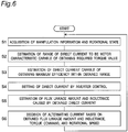
FIG. 6 is a flowchart for illustrating control processing of the drive control system inFIG. 1 . -
FIG. 7 is an explanatory diagram showing a configuration of a drive control system according to a second embodiment of the present invention. -
FIG. 8 is an explanatory diagram showing a configuration of a drive control system according to a third embodiment of the present invention. -
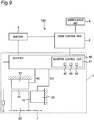
FIG. 9 is an explanatory diagram showing a configuration of a drive control system according to a fourth embodiment of the present invention. -
FIG. 10 is an explanatory diagram showing a configuration of a drive control system according to a fifth embodiment of the present invention. - Hereinafter, one embodiment of the present invention will be described in detail with reference to the drawings.
- The drive control system and the rotational electric machine of the present invention can be applied to a hybrid electric vehicle (HEV), an electric vehicle (EV), and an apparatus including an electric motor as a component. In the first embodiment, a drive control system and a rotational electric machine for an electric vehicle (EV) will be described as an example.
- As shown in
FIG. 1 , thedrive control system 100 according to the first embodiment includes a rotationalelectric machine 1, a drive control unit 2 (an example of a control apparatus), abattery 3, and amanipulation unit 4. - The rotational
electric machine 1 is attached to a drive wheel (not shown) directly or indirectly via a transaxle or the like, and drives and rotates the drive wheel. As shown inFIG. 1 , the rotationalelectric machine 1 includes astator 10 which generates a rotation magnetic field in response to an alternating current, arotor 20 which rotates in response to a rotation magnetic field, afield coil 30 which excites therotor 20 in response to a direct current, and aninverter 40. - The
stator 10 is disposed on the outer circumference centered on therotation shaft 7 and is configured irrotationally around therotation shaft 7. Therotor 20 is disposed on the inner circumference of thestator 10 and is configured rotatably around therotation shaft 7. Thefield coil 30 is disposed on one side in the rotation shaft direction of therotor 20 with respect to therotor 20 and is configured irrotationally around therotation shaft 7. - A
first air gap 13 is formed between thestator 10 and therotor 20 to deliver magnetic flux between thestator 10 and therotor 20. In addition, asecond air gap 14 is formed between thefield coil 30 and therotor 20 to deliver magnetic flux between thefield coil 30 and therotor 20. That is, thefield coil 30 is arranged in a row with therotor 20 to be shifted in the shaft direction of therotation shaft 7 with thesecond air gap 14 provided therebetween. - In addition, a permanent magnet (not shown) is arranged inside the
rotor 20. Ferrite magnets, SmCo magnets, AlNiCo magnets, neodymium bonded magnets, or the like can be used as permanent magnets. - The
inverter 40 converts the power supply voltage of thebattery 3 and inputs a direct current and a multiple-phase alternating current into the rotationalelectric machine 1. Theinverter 40 includes aninverter control unit 41 including a motorcharacteristic control unit 42 and a rotation magneticfield control unit 43. - The
inverter control unit 41 includes a CPU for performing calculations and the like, a storage medium such as a ROM and a RAM for storing programs, data, or the like to control the rotationalelectric machine 1, and an interface unit for inputting and outputting data with the outside. The motorcharacteristic control unit 42 and the rotation magneticfield control unit 43 have functions achieved in theinverter control unit 41 by the CPU of theinverter control unit 41 executing a predetermined program. - The motor
characteristic control unit 42 controls the direct current based on the manipulation information and the rotational state of therotor 20, which are acquired by theacquisition unit 50 of thedrive control unit 2 described below, to control the motor characteristic. The motorcharacteristic control unit 42 can freely set the application direction of direct current in an increase direction of the magnetic force of therotor 20 caused by the permanent magnet and/or in a decrease direction of the magnetic force of therotor 20 caused by the permanent magnet. Here, the motor characteristic refers to an output characteristic regarding the relationship between torque, rotational speed, and current obtained when the rotationalelectric machine 1 is operated as a motor (that is, an electric motor). - The rotation magnetic
field control unit 43 controls the alternating current based on the manipulation information and the rotational state of therotor 20, which are acquired by theacquisition unit 50, to control the rotation magnetic field of the rotationalelectric machine 1. Thereby, torque is generated in therotor 20. For example, when the rotation magneticfield control unit 43 performs PWM control on the power supply voltage of thebattery 3, the frequency and the amplitude of a multiple-phase alternating current to be input into the rotationalelectric machine 1 can be changed. The multiple-phase alternating current to be input into thestator 10 is controlled by the rotation magneticfield control unit 43, whereby the rotation magnetic field generated by thestator 10 being magnetized is controlled, and the speed and torque at which therotor 20 rotates with respect to thestator 10 change. Therefore, based on the manipulation information acquired by theacquisition unit 50, the rotation magneticfield control unit 43 can change the output torque of the rotationalelectric machine 1 so as to approach the requested torque of the manipulator (for example, the driver of a vehicle). The rotation magneticfield control unit 43 may perform field weakening control on the rotationalelectric machine 1 by further performing vector control on the multiple-phase alternating current. - The
battery 3 supplies power to the rotationalelectric machine 1 and thedrive control unit 2. - The
manipulation unit 4 accepts manipulation such as accelerator manipulation of the driver. - The
drive control unit 2 controls the drive of the EV by outputting a manipulation command to each unit constituting thedrive control system 100 based on the manipulation or the like accepted by themanipulation unit 4. Thedrive control unit 2 includes anacquisition unit 50. - The
acquisition unit 50 acquires manipulation information from themanipulation unit 4 and acquires the rotational state of the rotational electric machine 1 (that is, the rotor 20) via theinverter 40 from the rotation angle or the like detected by arotor angle sensor 5 disposed in the vicinity of the rotationalelectric machine 1. Specifically, theacquisition unit 50 acquires, as manipulation information, the accelerator manipulation amount, accelerator manipulation speed, and the like of the driver based on the manipulation or the like accepted by themanipulation unit 4. Theacquisition unit 50 estimates the requested torque of the manipulator from the acquired manipulation information. The acquisition unit decides the torque generated by or caused to be generated by therotor 20 from the estimated requested torque and the rotational state of therotor 20. That is, theacquisition unit 50 acquires manipulation information on the torque generated by or caused to be generated by therotor 20 and the rotational state of therotor 20. - The
drive control unit 2 includes a CPU for performing calculations and the like, a storage medium such as a ROM and a RAM for storing programs, data, or the like to control thedrive control system 100, and an interface unit for inputting and outputting data with the outside. Theacquisition unit 50 has a function achieved in thedrive control unit 2 by the CPU of thedrive control unit 2 executing a predetermined program. - Here, with reference to
FIGS. 2 to 5 , a control example of a motor characteristic in thedrive control system 100 will be described.FIGS. 2 to 5 are diagrams for illustrating motor characteristics achieved by control of direct current by the motorcharacteristic control unit 42. Hereinafter, "positive direct current" is defined as "direct current in the application direction increasing the magnetic force by the permanent magnet provided in therotor 20", and "negative direct current" is defined as "direct current in the application direction decreasing the magnetic force by the permanent magnet". - The first motor characteristic Mo shown in
FIG. 2 is a motor characteristic when direct current is controlled so that the value of the direct current for energizing thefield coil 30 reaches an intermediate value between the upper limit value and the lower limit value (that is, a set value) . In the case of the rotationalelectric machine 1, the first motor characteristic Mo is a motor characteristic in a state in which, for example, the motorcharacteristic control unit 42 sets the value of the direct current to zero and only the permanent magnet excites therotor 20. In the state of motor characteristic Mo, the rotationalelectric machine 1 can change the operating point within the range E1 with the control of the rotation magnetic field in the rotation magneticfield control unit 43, that is, the control of the frequency and the amplitude (effective current) of the multiple-phase alternating current to be input into the rotationalelectric machine 1. The output torque can take the range from zero to the maximum value T2 while the rotational speed of the rotationalelectric machine 1 is relatively low from zero to V1. When the rotational speed is higher than V1, the upper limit value of the output torque gradually decreases from the maximum value T2, and when the rotational speed is V4, the upper limit value of the output torque decreases to T1. When the rotational speed becomes higher than V4, the upper limit value of the output torque sharply decreases from T1 to almost zero. - The operating efficiency of the rotational electric machine 1 (that is, motor efficiency) differs depending on the operating point in the range E1, and distributes so as to draw a contour line in the range E1. For example, the range E2 having a predetermined high operating efficiency or more is limited to a partial region in the range E1. Normally, in the motor characteristic Mo of the rotational
electric machine 1, higher operating efficiency can be obtained between the rotational speed V2 higher than the rotational speed V1 at which the upper limit of the output torque starts to decrease and the rotational speed V3 lower than the rotational speed V4 at which the upper limit of the output torque sharply decreases. The operating efficiency of the rotational electric machine 1 (that is, motor efficiency) is represented by the ratio of the mechanical output (W) from the rotationalelectric machine 1 to the input power (W) into the rotationalelectric machine 1. - The motor characteristic Mm shown in
FIG. 3 is a motor characteristic when the direct current is controlled so that the value of the direct current reaches the lower limit (for example, a negative value), that is, a motor characteristic in a state where the magnetic force of therotor 20 is reduced. The motor characteristic Mm has a maximum value T2 of output torque lower than that of the motor characteristic Mo. On the other hand, the motor characteristic Mm has a maximum rotational speed V4 higher than that of the motor characteristic Mo. In the rotationalelectric machine 1, when the direct current for energizing thefield coil 30 is controlled to be negative, the amount of magnetic flux by the permanent magnet is equivalently reduced, and the torque constant and the induced voltage constant of the rotationalelectric machine 1 are reduced. Thus, the motor characteristic Mm has a reduced maximum value T2 of output torque of the rotationalelectric machine 1, and on the other hand, can have an increased maximum rotational speed V4, as compared with those of the motor characteristic Mo. - In addition, the motor characteristic Mp shown in
FIG. 4 is a motor characteristic when the direct current is controlled so that the value of the direct current reaches the upper limit (for example, a positive value), that is, a motor characteristic in a state where the magnetic force of therotor 20 is increased. The motor characteristic Mp has a reduced maximum rotational speed V4 but an increased maximum value T2 of output torque, as compared with those of the motor characteristic Mo. In the rotationalelectric machine 1, when the direct current for energizing thefield coil 30 is controlled to be positive, the amount of magnetic flux by the permanent magnet is equivalently increased, and the torque constant and the induced voltage constant of the rotationalelectric machine 1 is increased. Thus, the motor characteristic Mp has a reduced maximum rotational speed V4 of the rotationalelectric machine 1, but can have an increased maximum value T2 of output torque, as compared with those of the motor characteristic Mo. - Therefore, the motor
characteristic control unit 42 can vary the motor characteristic between the waveform of the motor characteristic Mm shown inFIG. 3 and the waveform of the motor characteristic Mp shown inFIG. 4 by setting the value of the direct current for energizing thefield coil 30 to any value from the upper limit to the lower limit and controlling the direct current so that the value of the direct current reaches the set value. Therefore, as shown inFIG. 5 , the equivalent motor characteristic Mx to be achieved by control of direct current is a motor characteristic having both an increased maximum value of the rotational speed and an increased maximum value of output torque such that the motor characteristics Mm, Mo, and Mp inFIGS. 2 to 4 are superimposed on each other. Thus, in thedrive control system 100 and the rotationalelectric machine 1, the output characteristic as a vehicle can be changed by changing the motor characteristic even without using a plurality of gear pairs or a mechanical transmission. - Next, with reference to
FIG. 6 , an example of control processing of a motor characteristic in thedrive control system 100 will be described. It should be noted that the processing described below is implemented by thedrive control unit 2 and theinverter control unit 41 executing a predetermined program. - As shown in
FIG. 6 , first, theacquisition unit 50 acquires manipulation information on the torque generated by or caused to be generated by therotor 20 and the rotational state of the rotor 20 (step S1). Then, theacquisition unit 50 sets a manipulation command (torque command) indicating a torque generated by or caused to be generated by therotor 20 based on the acquired manipulation information and the rotational state of therotor 20, and outputs the set torque command to the motorcharacteristic control unit 42. - Next, based on the torque command obtained from the
acquisition unit 50, the motorcharacteristic control unit 42 estimates the range of the direct current from which the motor characteristic capable of achieving the combination of the required torque value and the rotational speed can be obtained (step S2). The estimation processing of direct current in step S2 can be achieved by various methods. For example, the estimation processing of direct current may be performed by acquisition as mapping data stored in advance in the memory, and may be performed by acquisition as an operation result by a predetermined arithmetic expression or as information from the outside. In addition, the above-mentioned acquisition methods may be combined. - Subsequently, the motor
characteristic control unit 42 grasps the relationship between the direct current corresponding to the manipulation information and the rotational state of therotor 20 acquired by theacquisition unit 50, and the evaluation value. In addition, the motorcharacteristic control unit 42 estimates the value of the direct current at which the evaluation value is maximum (that is, the set value) in the range of the direct current estimated in step S2 (step S3). The evaluation value is a map data, a mathematical expression, or the like as a set of evaluation values acquired in advance by evaluation, and here, is the motor efficiency corresponding to the manipulation information and the rotational state of therotor 20 acquired by theacquisition unit 50. Then, the motorcharacteristic control unit 42 controls theinverter 40 so that the direct current for energizing thefield coil 30 is at a set value (step S4). This estimation may also be performed by acquisition as mapping data stored in advance in the memory, and may be performed by acquisition as an operation result by a predetermined arithmetic expression or as information from the outside. In addition, the above-mentioned acquisition methods may be combined. When the value of the optimum direct current fluctuates, the motorcharacteristic control unit 42 can also be configured to approach the optimum value by learning. Furthermore, an index other than the motor efficiency may be used as the evaluation value, and for example, the motor output may be used as the index. The motor output is represented by the maximum value of the mechanical output (W) that the rotationalelectric machine 1 can take, and is decided according to the value of the direct current for energizing thefield coil 30. In addition, an index that maximizes the sensory characteristics such as vibration or acceleration felt by the driver can also be used as the evaluation value. - In order to notify the rotation magnetic
field control unit 43 of the motor characteristics set in steps S1 to S4, the motorcharacteristic control unit 42 estimates the flux linkage amount to therotor 20 and the inductance generated by the field coil 30 (step S5) and outputs the estimated flux linkage amount and inductance to the rotation magneticfield control unit 43. This estimation may also be performed by acquisition as mapping data stored in advance in the memory, and may be performed by acquisition as an operation result by a predetermined arithmetic expression or as information from the outside. The motorcharacteristic control unit 42 may output the value of direct current, identification information indicating the motor characteristic, or the like, instead of the flux linkage amount, to the rotation magneticfield control unit 43. - The rotation magnetic
field control unit 43 performs the control of alternating current based on the motor characteristic grasped from the flux linkage amount and the inductance obtained from the motorcharacteristic control unit 42, the requested torque value required to be generated by therotor 20 grasped from the torque command, and the rotational speed grasped from the rotor angle sensor 5 (S6). When step S6 ends, the process returns to acquisition step S1 again, and the control processing of the acquisition step (step S1) and the motor characteristic control step (steps S2 to S6) is repeated at constant timings. - The
drive control system 100 and the rotationalelectric machine 1 of the present invention can be implemented by performing the control processing as illustrated above. The program and non-transitory storage medium of the present invention can be configured to be read by each of the control unit of the rotational electric machine 1 (for example, the inverter control unit 41) and the control unit of the drive control system (for example, the drive control unit 2), and cause the control units to perform the control processing illustrated above. As the storage medium, various storage media such as a ROM, a RAM, a HDD, a USB memory, a compact disc, and a magnetic medium can be applied. - The rotational
electric machine 1 can adopt not only the configuration shown inFIG. 1 but also, for example, the configuration shown inFIG. 7 (a second embodiment). That is, thefield coil 30 may be disposed, for example, on the inner circumference of therotor 20 with respect to therotor 20. - In
FIG. 7 , theinverter 40 and therotor angle sensor 5 are provided separately from the rotationalelectric machine 1. That is, theinverter 40 and therotor angle sensor 5 can be configured separately from the rotationalelectric machine 1. - The motor
characteristic control unit 42, the rotation magneticfield control unit 43, and theacquisition unit 50 are not limited to the configuration shown inFIG. 1 . For example, the motorcharacteristic control unit 42, the rotation magneticfield control unit 43, and theacquisition unit 50 may be provided in thedrive control unit 2 as shown inFIG. 8 (third embodiment), may be provided in theinverter control unit 41 as shown inFIG. 9 (fourth embodiment), and may be provided in anothercontrol unit 102 provided separately from thedrive control unit 2 and theinverter control unit 41 as shown inFIG. 10 (fifth embodiment). -
FIG. 10 shows, as an example, thedrive control system 100 and the rotationalelectric machine 1 in the case of being applied to a hybrid electric vehicle (HEV) with a combined use of a torque converter. InFIG. 10 , the rotationalelectric machine 1 is disposed between theengine 8 and thetransmission 9 along therotation shaft 7. The rotationalelectric machine 1 according to the fifth embodiment includes astator 10, arotor 20, afield coil 30, and acontrol unit 102 including anacquisition unit 50 and a motorcharacteristic control unit 42. The rotation magneticfield control unit 43 is provided in theinverter control unit 41 of theinverter 40 and is not provided in the rotationalelectric machine 1. In the fifth embodiment, therotor 20 may be integrally configured with the torque converter. In this case, for example, therotor 20 is configured by attaching a magnetic pole member to be therotor 20 to a casing of the torque converter. - In each of the embodiments described above, since the
field coil 30 generates the magnetic force similar to that of a permanent magnet, therotor 20 does not necessarily include a permanent magnet. When therotor 20 is not provided with a permanent magnet, the motor characteristic can be changed as inFIGS. 2 to 4 by changing the magnitude of the direct current flowing in one direction. It should be noted that when the permanent magnet is provided, the torque generated by or caused to be generated by therotor 20 can be relatively increased as compared with the case where the permanent magnet is not provided. - It should be noted that appropriately combining any embodiment or modification out of the various embodiments or modifications allows the effect of each embodiment or modification to be exhibited. In addition, a combination of the embodiments, a combination of the examples, or a combination of the embodiment and the example is possible, and a combination of the features out of different embodiments or the examples is also possible.
- The present invention can be applied to, for example, a control method for a vehicle drive motor, a program for controlling a vehicle drive motor, a storage medium storing a program for controlling a vehicle drive motor, and a control system for a vehicle drive motor.
-
- 1:
- rotational electric machine
- 2:
- drive control unit
- 3:
- battery
- 4:
- manipulation unit
- 5:
- rotor angle sensor
- 7:
- rotation shaft
- 10:
- stator
- 13:
- first air gap
- 14:
-
second air gap 14 - 20:
- rotor
- 30:
- field coil
- 40:
- inverter
- 41:
- inverter control unit
- 42:
- motor characteristic control unit
- 43:
- rotation magnetic field control unit
- 50:
- acquisition unit
- 100:
- drive control system
- T1, T2:
- output torque
- V1, V2, V3, V4:
- rotational speed
- E1, E2:
- range
- Mo, Mm, Mp:
- motor characteristic
Claims (14)
- A rotational electric machine (1) comprising:a stator (10) configured to generate a rotation magnetic field in response to alternating current;a rotor (20) configured to rotate in response to the rotation magnetic field;a field coil (30) configured to excite the rotor (20) in response to direct current;an acquisition unit (50) configured to acquire manipulation information related to a torque generated by or caused to be generated by the rotor (20) and a rotational state of the rotor (20); anda motor characteristic control unit (42) configured to control the direct current based on the manipulation information and the rotational state acquired by the acquisition unit (50) to control a motor characteristic.
- The rotational electric machine (1) according to claim 1, wherein
the motor characteristic control unit (42) grasps a relationship between the direct current corresponding to the manipulation information and the rotational state acquired by the acquisition unit (50), and an evaluation value, and sets the direct current at which the evaluation value is maximized. - The rotational electric machine (1) according to claim 2, wherein
the evaluation value relates to3.1 a motor efficiency corresponding to the manipulation information and the rotational state or3.2 a motor output. - The rotational electric machine (1) according to any one of claims 1 to 3, further comprising
a rotation magnetic field control unit (43) configured to control the rotation magnetic field. - The rotational electric machine (1) according to any one of claims 1 to 4, wherein
the rotor (20) includes a permanent magnet. - The rotational electric machine (1) according to claim 5, wherein
the motor characteristic control unit (42) is configured to freely set an application direction of the direct current6.1 in an increase direction of a magnetic force of the rotor caused by the permanent magnet or/and6.2 in a decrease direction of the magnetic force of the rotor caused by the permanent magnet. - A drive control system of a vehicle, the system comprising:a rotational electric machine (1) according to any of the claims 1 to 6;a manipulation unit (4) configured to be capable of accepting manipulation of the vehicle;a rotation magnetic field control unit (43) configured to control the rotation magnetic field based on manipulation accepted by the manipulation unit (4);wherein the acquisition unit (50) is configured to acquire manipulation information related to torque generated by or caused to be generated by the rotor (20) from manipulation accepted by the manipulation unit (4), the acquisition unit being configured to acquire a rotational state from the rotor (20); andwherein the motor characteristic control unit (42) is configured to control the direct current based on the manipulation information and the rotational state, which are acquired by the acquisition unit (50), to control a motor characteristic.
- The drive control system of a vehicle according to claim 7, wherein
the motor characteristic control unit (42) grasps a relationship between the direct current corresponding to the manipulation information and the rotational state acquired by the acquisition unit (50), and an evaluation value, and sets the direct current at which the evaluation value is maximized. - The drive control system of a vehicle according to claim 8, wherein
the evaluation value relates to9.1 a motor efficiency corresponding to the manipulation information and the rotational state or9.2 a motor output. - The drive control system of a vehicle according to any one of claims 7 to 9, wherein
the rotor (20) includes a permanent magnet. - The drive control system of a vehicle according to claim 10, wherein
the motor characteristic control unit is configured to freely set an application direction of the direct current11.1 in an increase direction of a magnetic force of the rotor caused by the permanent magnet or/and11.2 in a decrease direction of the magnetic force of the rotor caused by the permanent magnet. - A non-transitory computer-readable storage medium storing a program for causing a control apparatus, which is configured to control a rotational electric machine (1) including a stator (10) configured to generate a rotation magnetic field in response to alternating current, a rotor (20) configured to rotate in response to the rotation magnetic field, and a field coil (30) configured to excite the rotor (20) in response to direct current, to perform operations comprising:an acquisition step of acquiring manipulation information related to torque generated by or caused to be generated by the rotor (20) and a rotational state of the rotor (20); anda motor characteristic control step of controlling the direct current based on the manipulation information and the rotational state, which are acquired, to control a motor characteristic.
- The computer-readable storage medium according to claim 12, wherein
the motor characteristic control step includes grasping a relationship between the direct current corresponding to the manipulation information and the rotational state, which are acquired, and an evaluation value, and setting the direct current at which the evaluation value is maximized. - The computer-readable storage medium according to claim 13, wherein
the evaluation value relates to14.1 a motor efficiency corresponding to the manipulation information and the rotational state or14.2 a motor output.
Applications Claiming Priority (2)
| Application Number | Priority Date | Filing Date | Title |
|---|---|---|---|
| JP2018188326 | 2018-10-03 | ||
| JP2019128403A JP7326050B2 (en) | 2018-10-03 | 2019-07-10 | A rotating electric machine, a drive control system for a vehicle, a program to be executed by a control device for the rotating electric machine, and a storage medium storing the program |
Publications (1)
| Publication Number | Publication Date |
|---|---|
| EP3633846A1 true EP3633846A1 (en) | 2020-04-08 |
Family
ID=68109247
Family Applications (1)
| Application Number | Title | Priority Date | Filing Date |
|---|---|---|---|
| EP19200874.6A Withdrawn EP3633846A1 (en) | 2018-10-03 | 2019-10-01 | Rotational electric machine, drive control system of vehicle, and storage medium having program executed by or caused to be executed by control apparatus of rotational electric machine |
Country Status (3)
| Country | Link |
|---|---|
| US (1) | US10931221B2 (en) |
| EP (1) | EP3633846A1 (en) |
| CN (1) | CN110994929B (en) |
Families Citing this family (2)
| Publication number | Priority date | Publication date | Assignee | Title |
|---|---|---|---|---|
| US12240328B2 (en) | 2019-05-24 | 2025-03-04 | Exedy Globalparts Corporation | P2 module architecture |
| US11888424B1 (en) * | 2022-07-18 | 2024-01-30 | Tula eTechnology, Inc. | Methods for improving rate of rise of torque in electric machines with stator current biasing |
Citations (5)
| Publication number | Priority date | Publication date | Assignee | Title |
|---|---|---|---|---|
| US20030178973A1 (en) * | 2002-03-20 | 2003-09-25 | Denso Corporation | Power generation control apparatus for vehicle |
| EP1424764A2 (en) * | 2002-11-29 | 2004-06-02 | Mitsubishi Denki Kabushiki Kaisha | Vehicular generator-motor system |
| US20040145355A1 (en) * | 2003-01-29 | 2004-07-29 | Denso Corporation | Torque computation unit for vehicle generator |
| US20060192533A1 (en) * | 2005-01-25 | 2006-08-31 | Denso Corporation | Method and apparatus for calculating/controlling power generation torque |
| JP2016105696A (en) | 2016-03-07 | 2016-06-09 | 日立アプライアンス株式会社 | Permanent magnet synchronous machine |
Family Cites Families (6)
| Publication number | Priority date | Publication date | Assignee | Title |
|---|---|---|---|---|
| JPH0731006A (en) * | 1993-07-08 | 1995-01-31 | Motor Jidosha Kk | Synchronous motor controller for electric automobile |
| WO2007007387A1 (en) * | 2005-07-11 | 2007-01-18 | Hitachi, Ltd. | Controller of field winding type synchronous motor, electric drive system, electric four wheel driving vehicle, and hybrid automobile |
| JP6305364B2 (en) * | 2014-05-28 | 2018-04-04 | 三菱電機株式会社 | Rotating electrical machine system |
| JP6507721B2 (en) * | 2015-03-05 | 2019-05-08 | スズキ株式会社 | Electric rotating machine and current input control method of electric rotating machine |
| JP6614986B2 (en) * | 2016-02-02 | 2019-12-04 | 株式会社エクセディ | Power transmission device with rotating electric machine |
| JP2019118241A (en) * | 2017-12-27 | 2019-07-18 | 日本電産トーソク株式会社 | Motor controller |
-
2019
- 2019-09-26 US US16/584,325 patent/US10931221B2/en active Active
- 2019-09-27 CN CN201910925083.8A patent/CN110994929B/en active Active
- 2019-10-01 EP EP19200874.6A patent/EP3633846A1/en not_active Withdrawn
Patent Citations (5)
| Publication number | Priority date | Publication date | Assignee | Title |
|---|---|---|---|---|
| US20030178973A1 (en) * | 2002-03-20 | 2003-09-25 | Denso Corporation | Power generation control apparatus for vehicle |
| EP1424764A2 (en) * | 2002-11-29 | 2004-06-02 | Mitsubishi Denki Kabushiki Kaisha | Vehicular generator-motor system |
| US20040145355A1 (en) * | 2003-01-29 | 2004-07-29 | Denso Corporation | Torque computation unit for vehicle generator |
| US20060192533A1 (en) * | 2005-01-25 | 2006-08-31 | Denso Corporation | Method and apparatus for calculating/controlling power generation torque |
| JP2016105696A (en) | 2016-03-07 | 2016-06-09 | 日立アプライアンス株式会社 | Permanent magnet synchronous machine |
Also Published As
| Publication number | Publication date |
|---|---|
| CN110994929B (en) | 2024-05-03 |
| US10931221B2 (en) | 2021-02-23 |
| US20200112282A1 (en) | 2020-04-09 |
| CN110994929A (en) | 2020-04-10 |
Similar Documents
| Publication | Publication Date | Title |
|---|---|---|
| JP4879657B2 (en) | Electric motor control device | |
| CN104813582B (en) | Method and apparatus for reducing the change in torque in electric motor drive system | |
| JP6998717B2 (en) | Variable magnetic force motor control method and control device | |
| US10931221B2 (en) | Rotational electric machine, drive control system of vehicle, and storage medium having program executed by or caused to be executed by control apparatus of rotational electric | |
| EP3288180A1 (en) | Circuit and control method for the same | |
| JP2015104295A (en) | Control device for electric automobile | |
| JP2013099245A (en) | Rotor time constant estimation device for induction motor | |
| EP3188358A1 (en) | Control device for switched reluctance motor | |
| JP7099225B2 (en) | Motor control device | |
| JP7326050B2 (en) | A rotating electric machine, a drive control system for a vehicle, a program to be executed by a control device for the rotating electric machine, and a storage medium storing the program | |
| JP5164440B2 (en) | Constant speed control device for variable field motor | |
| JP2018019528A (en) | Controller for switched reluctance motor | |
| WO2017119432A1 (en) | Motor drive device | |
| US20210305926A1 (en) | Rotational electric machine, drive control system, and power generation method | |
| CN112532119A (en) | Control device for motor | |
| RU2840717C2 (en) | Processing device, electric vehicle, processing method and program | |
| EP2869460A1 (en) | Motor control device | |
| EP3490137B1 (en) | Controller for switched reluctance motor | |
| JP6950409B2 (en) | Drive device | |
| JP7522382B2 (en) | Processing device, electric vehicle, processing method, and program | |
| JP6615919B2 (en) | Rotating electrical machine system and vehicle equipped with the rotating electrical machine system | |
| Menn et al. | Holistic analytical design of induction motors for automotive application | |
| JP2019097301A (en) | Control device for switched reluctance motor | |
| EP1622253A2 (en) | Control process and control device of induction motor, and steel/nonferrous facility, railway vehicle, winder, vessel, machine tool, paper machine facility and transport facility employing the control process and the control device | |
| JP2025094731A (en) | Program for controlling variable magnetic flux motor |
Legal Events
| Date | Code | Title | Description |
|---|---|---|---|
| PUAI | Public reference made under article 153(3) epc to a published international application that has entered the european phase |
Free format text: ORIGINAL CODE: 0009012 |
|
| STAA | Information on the status of an ep patent application or granted ep patent |
Free format text: STATUS: THE APPLICATION HAS BEEN PUBLISHED |
|
| AK | Designated contracting states |
Kind code of ref document: A1 Designated state(s): AL AT BE BG CH CY CZ DE DK EE ES FI FR GB GR HR HU IE IS IT LI LT LU LV MC MK MT NL NO PL PT RO RS SE SI SK SM TR |
|
| AX | Request for extension of the european patent |
Extension state: BA ME |
|
| 18D | Application deemed to be withdrawn |
Effective date: 20201009 |