EP3633823B1 - Terminal wireless charging receiving device and transmitting device, and wireless charging system - Google Patents
Terminal wireless charging receiving device and transmitting device, and wireless charging system Download PDFInfo
- Publication number
- EP3633823B1 EP3633823B1 EP18820428.3A EP18820428A EP3633823B1 EP 3633823 B1 EP3633823 B1 EP 3633823B1 EP 18820428 A EP18820428 A EP 18820428A EP 3633823 B1 EP3633823 B1 EP 3633823B1
- Authority
- EP
- European Patent Office
- Prior art keywords
- coils
- wireless charging
- mobile terminal
- rear housing
- coil
- Prior art date
- Legal status (The legal status is an assumption and is not a legal conclusion. Google has not performed a legal analysis and makes no representation as to the accuracy of the status listed.)
- Active
Links
Images




Classifications
-
- H—ELECTRICITY
- H02—GENERATION; CONVERSION OR DISTRIBUTION OF ELECTRIC POWER
- H02J—ELECTRIC POWER NETWORKS; CIRCUIT ARRANGEMENTS OR SYSTEMS FOR SUPPLYING OR DISTRIBUTING ELECTRIC POWER; SYSTEMS FOR STORING ELECTRIC ENERGY
- H02J50/00—Circuit arrangements or systems for wireless supply or distribution of electric power
- H02J50/10—Circuit arrangements or systems for wireless supply or distribution of electric power using inductive coupling
-
- H—ELECTRICITY
- H01—ELECTRIC ELEMENTS
- H01F—MAGNETS; INDUCTANCES; TRANSFORMERS; SELECTION OF MATERIALS FOR THEIR MAGNETIC PROPERTIES
- H01F38/00—Adaptations of transformers or inductances for specific applications or functions
- H01F38/14—Inductive couplings
-
- H—ELECTRICITY
- H02—GENERATION; CONVERSION OR DISTRIBUTION OF ELECTRIC POWER
- H02J—ELECTRIC POWER NETWORKS; CIRCUIT ARRANGEMENTS OR SYSTEMS FOR SUPPLYING OR DISTRIBUTING ELECTRIC POWER; SYSTEMS FOR STORING ELECTRIC ENERGY
- H02J50/00—Circuit arrangements or systems for wireless supply or distribution of electric power
- H02J50/005—Mechanical details of housing or structure aiming to accommodate the power transfer means, e.g. mechanical integration of coils, antennas or transducers into emitting or receiving devices
-
- H—ELECTRICITY
- H02—GENERATION; CONVERSION OR DISTRIBUTION OF ELECTRIC POWER
- H02J—ELECTRIC POWER NETWORKS; CIRCUIT ARRANGEMENTS OR SYSTEMS FOR SUPPLYING OR DISTRIBUTING ELECTRIC POWER; SYSTEMS FOR STORING ELECTRIC ENERGY
- H02J50/00—Circuit arrangements or systems for wireless supply or distribution of electric power
- H02J50/70—Circuit arrangements or systems for wireless supply or distribution of electric power involving the reduction of electric, magnetic or electromagnetic leakage fields
-
- H—ELECTRICITY
- H02—GENERATION; CONVERSION OR DISTRIBUTION OF ELECTRIC POWER
- H02J—ELECTRIC POWER NETWORKS; CIRCUIT ARRANGEMENTS OR SYSTEMS FOR SUPPLYING OR DISTRIBUTING ELECTRIC POWER; SYSTEMS FOR STORING ELECTRIC ENERGY
- H02J7/00—Circuit arrangements for charging or discharging batteries or for supplying loads from batteries
- H02J7/02—Circuit arrangements for charging or discharging batteries or for supplying loads from batteries for charging batteries from AC mains by converters
-
- H—ELECTRICITY
- H04—ELECTRIC COMMUNICATION TECHNIQUE
- H04M—TELEPHONIC COMMUNICATION
- H04M1/00—Substation equipment, e.g. for use by subscribers
- H04M1/02—Constructional features of telephone sets
- H04M1/0202—Portable telephone sets, e.g. cordless phones, mobile phones or bar type handsets
- H04M1/026—Details of the structure or mounting of specific components
- H04M1/0264—Details of the structure or mounting of specific components for a camera module assembly
-
- H—ELECTRICITY
- H01—ELECTRIC ELEMENTS
- H01F—MAGNETS; INDUCTANCES; TRANSFORMERS; SELECTION OF MATERIALS FOR THEIR MAGNETIC PROPERTIES
- H01F27/00—Details of transformers or inductances, in general
- H01F27/02—Casings
-
- H—ELECTRICITY
- H02—GENERATION; CONVERSION OR DISTRIBUTION OF ELECTRIC POWER
- H02J—ELECTRIC POWER NETWORKS; CIRCUIT ARRANGEMENTS OR SYSTEMS FOR SUPPLYING OR DISTRIBUTING ELECTRIC POWER; SYSTEMS FOR STORING ELECTRIC ENERGY
- H02J50/00—Circuit arrangements or systems for wireless supply or distribution of electric power
- H02J50/40—Circuit arrangements or systems for wireless supply or distribution of electric power using two or more transmitting or receiving devices
- H02J50/402—Circuit arrangements or systems for wireless supply or distribution of electric power using two or more transmitting or receiving devices the two or more transmitting or the two or more receiving devices being integrated in the same unit, e.g. power mats with several coils or antennas with several sub-antennas
-
- H—ELECTRICITY
- H04—ELECTRIC COMMUNICATION TECHNIQUE
- H04M—TELEPHONIC COMMUNICATION
- H04M2201/00—Electronic components, circuits, software, systems or apparatus used in telephone systems
- H04M2201/08—Magnetic elements
Definitions
- Embodiments of the present invention relate to the wireless charging field, and more specifically, to a wireless charging receiving apparatus or transmitting apparatus, or system of a mobile terminal.
- a rear housing of a mobile terminal is certainly a part in contact with a palm for a longest time.
- a metal rear housing has the following advantages: The metal rear housing has good quality, a good touch feel, and is relatively easy to be integrally molded. A metal material has both abrasion resistance and falling resistance. The metal rear housing is only deformed when suffering a strong crash, but cannot shatter as easily as glass.
- a wireless charging receiving coil needs to be mounted in the smartphone.
- the wireless charging receiving coil is configured to receive an electromagnetic wave generated by a wireless charging transmitting coil on a wireless charger, to charge the smartphone.
- the metal rear housing affects a signal of the smartphone, and a high frequency magnetic field cannot penetrate the metal rear housing. Therefore, a hole or a seam needs to be specially formed to damage the rear housing, and a supporting strength and aesthetic appearance of the metal rear housing are reduced.
- a diameter of an acceptable hole formed on the rear housing of the smartphone is excessively small for a conventional coil design. Coupling between the wireless charging transmitting coil and the wireless charging receiving coil mounted in the smartphone is insufficient, resulting in low power transmission efficiency.
- the metal rear housing generates an eddy current (as shown in FIG. 1 ) due to a magnetic field generated by the wireless charging transmitting coil. Consequently, the metal rear housing rapidly generates heat, resulting in an energy loss and severely affecting user experience.
- WO 2015/067854 A1 discloses an apparatus which includes a first layer having a first coil, a second layer having a second coil, and a third layer located under the second layer.
- the first coil and the second coil are stacked relative to each other and configured to be located at an aperture of a housing member including electrically conductive material.
- the third layer includes a ferrite member located under the second coil such that the second coil is between the first coil and the ferrite member.
- the first coil or the second coil has a substantially "8" shape with opposite winding arrangement.
- the mobile device housing may have an aperture formed in a rear surface of the housing in which the stack of coils and ferro-magnetic member are housed.
- a camera lens and/or flash may also be included within the inner periphery of the coils.
- US 2016/285317 A1 discloses a wireless power transmitter.
- two coils are magnetically coupled together by placing both coils on a magnetic layer.
- a power circuit generates an AC signal of a defined voltage magnitude that causes a current to flow through the first coil, which generates a magnetic field having a first polarity.
- the second coil is coupled to the first coil.
- Current flows through the second coil and generates a magnetic field having a second polarity that is opposite from the first polarity. Because the magnetic field generated by each coil has a different polarity, the magnetic fields attract and form a strong magnetic field that flows from the first coil to the second coil.
- the strong magnetic field can transfer greater amounts of power to a receiver in comparison to coil configurations that emit magnetic fields in the same direction that repel one another.
- EP 3 131208 A1 discloses an 8-shaped NFC antenna with a metal back cover.
- the 8-shaped NFC antenna comprises a metal back cover and an antenna coil
- the metal back cover comprises a first through-hole and a second through-hole
- the antenna coil is located on the inner side of the metal back cover
- the metal back cover is further provided with a first slit
- the first slit is connected with the first through-hole and the second through-hole
- the antenna coil surrounding the first through-hole and the second through-hole is in an 8 shape
- the current direction of the part of the coil surrounding the first through-hole and the current direction of the part of the coil surrounding the second through-hole are opposite.
- the finger print identification module, the camera module, the flashlight module or other sensor modules can be arranged in the first through-hole and the second through-hole respectively.
- a reconfigurable coil may include a first conductive portion and second conductive portion. Two or more configurations may be established. These configurations may correspond to particular current paths. For example, in a circular configuration, a path is provided having the same rotational sense in both first and second conductive portions. However, in a figure eight configuration, a path is provided having a first rotational sense in the first conductive portion and a second rotational sense in the second conductive portion. A switch coupled between these portions may set the coil's configuration. Configurations may be selected based on one or more operation conditions involving the coil.
- Embodiments of the present invention provide a wireless charging receiving apparatus, transmitting apparatus, and system of a mobile terminal.
- Two coils generating electromagnetic induction are configured as interconnected coils, the two coils are located in a same plane and are connected in series, and winding directions of the two coils are opposite, so that directions of magnetic fields generated by the two coils are opposite, thereby resolving a problem of an eddy current on a metal rear housing of the mobile terminal such as a smartphone including the wireless charging system, and reducing a temperature of a metal body and reducing an energy loss without forming a hole or a seam on the metal rear housing.
- an embodiment of the present invention provides a mobile terminal, including a wireless charging receiving apparatus, a metal rear housing, and three components, where the wireless charging receiving apparatus is disposed inside the mobile terminal and close to a metal rear housing of the mobile terminal, the wireless charging receiving apparatus includes two interconnected coils, the two coils are located in a same plane and are connected in series, and winding directions of the two coils are opposite, so that directions of magnetic fluxes generated by the two coils on the metal rear housing are opposite.
- the three components are a camera flash, a fingerprint recognition apparatus, and a camera
- the two coils separately surround two components of the camera flash, the fingerprint recognition apparatus, and the camera on the metal rear housing, wherein a distance between the two components is smaller than distances between other two components of the three components, so that the two coils generate electromagnetic induction with a magnetic field generated by a wireless charging transmitting apparatus that charges the mobile terminal.
- a total magnetic flux generated by the two coils at a position of the metal rear housing of the mobile terminal other than the position at which the camera flash, or the fingerprint recognition apparatus, or the camera is disposed is zero.
- the two coils are identical coils.
- the coils are disposed at the position of the camera flash, or the fingerprint recognition apparatus, or the camera. There is no need to form another hole at another position of the metal rear housing, thereby reducing a quantity of holes.
- an electromagnetic signal is no longer shielded by the metal rear housing, and 3 electromagnetic induction efficiency is high.
- the two coils are configured as identical coils, so that a process may be simplified, and a total magnetic flux of zero may be easily and conveniently achieved under magnetic fields.
- the two coils may alternatively be coils having different shapes or winding quantities, provided that the magnetic fluxes generated by the two coils are the same.
- a wireless charging coil having a butterfly structure or a figure-8 structure may be used.
- an embodiment of the present invention provides a wireless charging system of a mobile terminal, including the mobile terminal according to any one implementation of the first aspect and a wireless charger.
- a receiving apparatus is disposed in the mobile terminal, and a transmitting apparatus is disposed on a wireless charger.
- the receiving apparatus and the transmitting apparatus each include two interconnected coils, the two interconnected coils are located in a same plane and are connected in series, and winding directions of the two interconnected coils are opposite.
- magnetic fluxes of the magnetic fields generated by the two interconnected coils in the receiving apparatus on the metal rear housing are the same, and magnetic fluxes of the magnetic fields generated by the two interconnected coils in the transmitting apparatus on the metal rear housing are also the same.
- electromagnetic induction is generated between the two interconnected coils of the receiving apparatus and the two interconnected coils of the transmitting apparatus.
- the two coils generating electromagnetic induction are configured as interconnected coils, the two coils are located in the same plane and are connected in series, and the winding directions of the two coils are opposite, so that the directions of the magnetic fields generated by the two coils are opposite, thereby resolving a problem of an eddy current on the metal rear housing of the mobile terminal such as a smartphone including the wireless charging system, and reducing a temperature of a metal body and reducing an energy loss without forming a hole or a seam on the metal rear housing.
- the directions of the magnetic fields generated by the two coils are opposite and magnitude of the magnetic fields is the same, so that the magnetic fluxes generated on the metal rear housing counterbalance each other, to eliminate eddy currents generated by the two coils on the metal rear housing.
- a mobile terminal in the embodiments of the present invention may be applied to various charging scenarios.
- the mobile terminal is neither limited to a smartphone, a tablet computer, and a wearable device, nor limited to various mobile terminal devices such as an electric automobile. This is not limited in the embodiments of the present invention.
- a wireless charging receiving apparatus of a mobile terminal may include a wireless charging receiving coil 21, a rectifier circuit 22, a voltage regulator 23, and a controller 24.
- the wireless charging receiving coil 21 generates electric energy in a magnetic field generated by a wireless charging transmitting apparatus, and finally outputs a voltage to a load after regulation performed by the rectifier circuit 22 and the voltage regulator 23 under control of the controller 24.
- the receiving apparatus is disposed inside a mobile terminal device, for example, disposed inside a mobile phone.
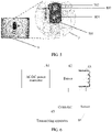
- FIG. 3 is a schematic diagram of a magnetic circuit of a wireless charging receiving coil in a wireless charging receiving apparatus of a mobile terminal according to an embodiment of the present invention.
- the wireless charging receiving apparatus is disposed inside the mobile terminal and close to a metal rear housing 3 of the mobile terminal, and includes a wireless charging coil 6 including two interconnected coils in this embodiment of the present invention.
- the two interconnected coils included in the coil 6 are coils 701 and 702.
- the coils 701 and 702 are located in a same plane and are connected in series, and winding directions of the two coils 701 and 702 are opposite, so that directions of magnetic fluxes generated by the two coils 701 and 702 on the metal rear housing 3 are opposite.
- the two coils 701 and 702 are configured as interconnected coils.
- the two coils 701 and 702 are located in the same plane and are connected in series, and the winding directions of the two coils 701 and 702 are opposite, so that directions of magnetic fields generated by the two coils 701 and 702 are opposite. Therefore, magnetic fluxes generated on the metal rear housing counterbalance each other, to reduce or eliminate an eddy current on the metal rear housing 3. Therefore, a temperature of the metal rear housing 3 can be reduced when no seam is formed on the metal rear housing, and an energy loss is reduced while a mechanical supporting degree of a metal body is ensured.
- magnetic fluxes of the magnetic fields generated by the two coils 701 and 702 on the metal rear housing 3 are the same, so that a total magnetic flux passing through the metal rear housing 3 is zero.
- the directions of the magnetic fields generated by the two coils 701 and 702 are opposite and magnitude of the magnetic fields is the same. Therefore, the magnetic fluxes generated on the metal rear housing 3 counterbalance each other, to eliminate eddy currents generated by the two coils 701 and 702 on the metal rear housing 3. Therefore, the temperature of the metal rear housing 3 can be reduced when no seam is formed on the metal rear housing 3, and the energy loss is reduced while the mechanical supporting degree of the metal body is ensured.
- the plane in which the two coils 701 and 702 are located is parallel to the metal rear housing 3.
- the two coils 701 and 702 are correspondingly disposed at a position that is parallel to a position of a camera flash, or a fingerprint recognition apparatus, or a camera on the metal rear housing 3, so that the two coils 701 and 702 generate electromagnetic induction with a magnetic line entering the mobile terminal from the position of the camera flash, or the fingerprint recognition apparatus, or the camera.
- the coils are disposed at the position of the camera flash, or the fingerprint recognition apparatus, or the camera. There is no need to form another hole at another position of the metal rear housing 3, thereby reducing a quantity of holes.
- the two coils 701 and 702 are disposed at the camera on the metal rear housing 3 of the mobile terminal.
- the camera is a dual camera
- one of the two coils surrounds one camera of the dual camera
- the other coil surrounds the other camera of the dual camera.
- the two coils 701 and 702 are parallel to a plane in which the dual camera is located.
- each of the two coils 701 and 702 is disposed at a camera, so that the two coils 701 and 702 generate electromagnetic induction with a coil of a wireless charger.
- the two coils 701 and 702 generate, through the position of the camera flash, or the fingerprint recognition apparatus, or the camera, electromagnetic induction with a magnetic field generated by a wireless charging transmitting apparatus of the mobile terminal. At the position of the camera flash, or the fingerprint recognition apparatus, or the camera, an electromagnetic signal is no longer shielded by the metal rear housing 3, and electromagnetic induction efficiency is high.
- the two coils 701 and 702 generate, through a position of the dual camera, electromagnetic induction with the magnetic field generated by the wireless charging transmitting apparatus of the mobile terminal.
- a total magnetic flux generated by the two coils 701 and 702 at a position of the metal rear housing 3 of the mobile terminal other than the position at which the camera flash, or the fingerprint recognition apparatus, or the camera is disposed is zero.
- a wireless charging coil having a butterfly structure or a figure-8 structure may be used.
- the butterfly structure or the figure-8 structure is a structure in which two single toroid coils intersect.
- Each toroid coil may be of various shapes, such as a ring shape, an oval shape, or a rectangular shape.
- the shape of the single toroid coil is not limited herein.
- the two coils 701 and 702 are configured as identical coils.
- the two coils 701 and 702 are configured as identical coils, so that a process may be simplified, and a total magnetic flux of zero may be easily and conveniently achieved under magnetic fields.
- the two coils 701 and 702 may alternatively be coils having different shapes or winding quantities, provided that magnetic fluxes generated by the two coils are the same.
- the two coils 701 and 702 generating electromagnetic induction are configured as interconnected coils, the two coils 701 and 702 are located in a same plane and are connected in series, and winding directions of the two coils 701 and 702 are opposite, so that directions of magnetic fields generated by the two coils 701 and 702 are opposite, thereby resolving a problem of an eddy current on a metal rear housing 3 of a mobile terminal such as a smartphone including a wireless charging system, and reducing a temperature of a metal body and reducing an energy loss without forming a hole or a seam on the metal rear housing 3.
- the directions of the magnetic fields generated by the two coils 701 and 702 are opposite and magnitude of the magnetic fields is the same, so that the magnetic fluxes generated on the metal rear housing 3 counterbalance each other, to eliminate eddy currents generated by the two coils 701 and 702 on the metal rear housing 3.
- FIG. 4 shows a wireless charging coil that has a butterfly structure or a figure-8 structure according to some embodiments of this solution.
- the wireless charging coil is divided into two parts.
- a coil 1 is in a cross-connection to a coil 2, and a value of a magnetic flux generated by a current flowing through the coil 1 is equal to a value of a magnetic flux generated by the current flowing through the coil 2, but a direction of the magnetic flux generated by the current flowing through the coil 1 is opposite to a direction of the magnetic flux generated by the current flowing through the coil 2.
- the magnetic fluxes affect a metal rear housing 3 of a charging device of a terminal, a total magnetic flux generated on the metal rear housing 3 is zero.
- structures of a transmitting coil and a receiving coil are the same, and may be applied to a wireless charging receiving apparatus, transmitting apparatus, and system of a mobile terminal.
- a shape of the wireless charging coil is interconnected coils.
- the two coils 701 and 702 are located in a same plane and are connected in series, and winding directions of the two coils 701 and 702 are opposite, so that directions of magnetic fields generated by the two coils 701 and 702 are opposite. Therefore, magnetic fluxes generated on the metal rear housing 3 counterbalance each other, to reduce or eliminate an eddy current on the metal rear housing 3. Therefore, a temperature of the metal rear housing 3 can be reduced when no seam is formed on the metal rear housing 3, and an energy loss is reduced while a mechanical supporting degree of a metal body is ensured.
- the wireless charging coil having the butterfly structure or the figure-8 structure may be used.
- a wireless charging coil may alternatively include two connected square coils.
- a structure of a single coil is not specifically limited, provided that values of the magnetic fluxes generated by the current flowing through the two coils 701 and 702 are the same and directions of the magnetic fluxes are opposite.
- the two coils 701 and 702 are identical coils, a process may be simplified, and a total magnetic flux of zero may be easily and conveniently achieved under the magnetic fields.
- the two coils 701 and 702 may alternatively be coils having different shapes or winding quantities, provided that the magnetic fluxes generated by the two coils are the same.
- An application scenario of the wireless charging coil may be the wireless charging receiving apparatus, or transmitting apparatus, or system of the mobile terminal. Specifically, the plane in which the two coils 701 and 702 are located is parallel to the metal rear housing 3.
- the coils are disposed at a position of the camera flash, or a fingerprint recognition apparatus, or a camera. There is no need to form another hole at another position of the metal rear housing 3, thereby reducing a quantity of holes.
- the two coils 701 and 702 are disposed at the camera on the metal rear housing 3 of the mobile terminal.
- the two coils 701 and 702 are separately disposed at a position of one of the two cameras, and the two coils 701 and 702 are parallel to a plane in which the dual camera is located.
- each of the two coils 701 and 702 is disposed at a camera, so that the two coils 701 and 702 generate electromagnetic induction with a coil of a wireless charger.
- an electromagnetic signal is no longer shielded by the metal rear housing 3, and electromagnetic induction efficiency is high.
- An effect of using the wireless charging coil includes the following:
- the two coils 701 and 702 generating electromagnetic induction are configured as interconnected coils, the two coils 701 and 702 are located in the same plane and are connected in series, and the winding directions of the two coils 701 and 702 are opposite, so that the directions of the magnetic fields generated by the two coils 701 and 702 are opposite, thereby resolving a problem of an eddy current on the metal rear housing 3 of the mobile terminal such as a smartphone including a wireless charging system, and reducing the temperature of the metal body and reducing the energy loss without forming a hole or a seam on the metal rear housing 3.
- the directions of the magnetic fields generated by the two coils 701 and 702 are opposite and magnitude of the magnetic fields is the same, so that the magnetic fluxes generated on the metal rear housing 3 counterbalance each other, to eliminate eddy currents generated by the two coils 701 and 702 on the metal rear housing 3.
- FIG. 5 is a schematic structural diagram of a mobile terminal provided with the wireless charging coil according to another embodiment of the present invention.
- a mobile terminal includes a wireless charging receiving apparatus.
- the wireless charging receiving apparatus is disposed inside the mobile terminal and close to a metal rear housing 3 of the mobile terminal.
- the wireless charging receiving apparatus includes two interconnected coils.
- the mobile terminal further includes a dual camera. One of the two coils surrounds one camera of the dual camera, and the other coil surrounds the other camera of the dual camera.
- the two coils 701 and 702 when a dual camera 801 and 802 is disposed, to be specific, the coil 701 correspondingly surrounds the camera 801, and the coil 702 correspondingly surrounds the camera 802, the two coils 701 and 702 generate electromagnetic induction with a coil of a wireless charger. At a position of the camera, an electromagnetic signal is no longer shielded by the metal rear housing 3, and electromagnetic induction efficiency is high.
- the two coils 701 and 702 generate, through a position of the dual camera, electromagnetic induction with a magnetic field generated by a wireless charging transmitting apparatus of the mobile terminal. A total magnetic flux generated at a position other than the position of the camera is zero.
- the two coils 701 and 702 may be identical coils.
- a plane in which the two coils are located is parallel to the metal rear housing.
- a total magnetic flux generated by the two coils at a position on the metal rear housing of the mobile terminal other than a position at which a camera flash, or a fingerprint recognition apparatus, or a camera is disposed is zero, to eliminate a vortex generated when the magnetic field generated by the wireless charging transmitting apparatus penetrates the metal rear housing.
- the two coils 701 and 702 are located in the same plane and are connected in series, and winding directions of the two coils are opposite, so that directions of magnetic fluxes generated by the two coils on the metal rear housing 3 are opposite.
- the mobile terminal further includes at least two of three components: a camera flash, a fingerprint recognition apparatus, and a camera; one of the two coils surrounds one of the three components: the camera flash, the fingerprint recognition apparatus, and the camera on the metal rear housing; and the other coil surrounds one of remaining two of the camera flash, the fingerprint recognition apparatus, and the camera, so that the two coils generate electromagnetic induction due to a magnetic field of the mobile terminal entering through a position of the camera flash, or the fingerprint recognition apparatus, or the camera.
- the plane in which the two coils are located is parallel to the metal rear housing, and the two coils separately surround two of the camera flash, the fingerprint recognition apparatus, and the camera on the metal rear housing, where a distance between the two components is one of two smaller distances between the three components, so that the two coils generate electromagnetic induction with a magnetic field generated by a wireless charging transmitting apparatus that charges the mobile terminal.
- FIG. 6 shows a wireless charging transmitting apparatus of a mobile terminal according to some embodiments of the present invention.
- the transmitting apparatus may include an AC/DC power converter 61, a driver 62, a transmitting coil 63, a sensor 64, and a controller 65.
- the AC/DC power converter 61 converts the mains into a direct current.
- the transmitting coil 63 is configured to generate electromagnetic induction with a coil in a wireless charging receiving apparatus, so that the coil in the wireless charging receiving apparatus generates electric energy in a magnetic field generated by the transmitting coil 63 of transmitting apparatus.
- FIG. 7 is a schematic diagram of a magnetic circuit of a wireless charging transmitting apparatus of a mobile terminal according to some embodiments of the present invention.
- a transmitting coil 10 includes two interconnected coils.
- the two coils are located in a same plane and are connected in series, and winding directions of the two coils are opposite.
- directions of magnetic fields generated by the two coils are opposite, so that when the wireless charging transmitting apparatus of the mobile terminal charges the mobile terminal, directions of magnetic fluxes passing through a metal rear housing 3 of the mobile terminal are opposite, and magnetic fluxes of the magnetic fields generated by the two coils on the metal rear housing 3 are the same.
- the two coils may be identical coils, to simplify a process, and easily ensure that the directions of the magnetic fields generated by the two coils are opposite and magnitude of the magnetic fields is the same, so that the magnetic fluxes generated on the metal rear housing 3 counterbalance each other.
- the directions of the magnetic fields generated by the two coils of the transmitting apparatus are opposite and the magnitude of the magnetic fields is the same, so that the magnetic fluxes generated on the metal rear housing 3 counterbalance each other, thereby resolving a problem of an eddy current on the metal rear housing 3 of the mobile terminal such as a smartphone including a wireless charging system, and reducing a temperature of a metal body and reducing an energy loss without forming a hole or a seam on the metal rear housing 3.
- FIG. 8 shows a wireless charging system of a mobile terminal according to some examples not forming part of the invention, and the system includes a receiving apparatus and a transmitting apparatus.
- the transmitting apparatus may include an AC/DC power converter 61, a driver 62, a transmitting coil 63, a sensor 64, and a controller 65.
- the AC/DC power converter 61 converts the mains into a direct current.
- the receiving apparatus may include a wireless charging receiving coil 21, a rectifier circuit 22, a voltage regulator 23, and a controller 24.
- the transmitting coil 63 generates electromagnetic induction with the wireless charging receiving coil 21.
- the wireless charging receiving coil 21 generates electric energy in a magnetic field generated by the transmitting coil 63 of the wireless charging transmitting apparatus, and finally outputs a voltage to a load after regulation performed by the rectifier circuit 22 and the voltage regulator 23 under control of the controller 24.
- the receiving apparatus is disposed inside a mobile terminal device, for example, disposed inside a mobile phone.
- the transmitting apparatus is disposed on a wireless charger, and the receiving apparatus is disposed inside the mobile terminal.
- FIG. 9 is a schematic diagram of a magnetic circuit of a wireless charging system of a mobile terminal according to some embodiments of the present invention.
- a receiving apparatus and a transmitting apparatus respectively include a wireless charging receiving apparatus coil 6 and a wireless charging transmitting apparatus coil 10.
- the wireless charging receiving apparatus coil 6 and the wireless charging transmitting apparatus coil 10 each include two interconnected coils 701 and 702.
- the two coils 701 and 702 are located in a same plane and are connected in series, and winding directions of the two coils 701 and 702 are opposite. Electromagnetic induction is generated between the two coils of the receiving apparatus coil 6 and the two coils of the transmitting apparatus coil 10.
- the mobile terminal further includes at least two of three components: a camera flash, a fingerprint recognition apparatus, and a camera; one of the two coils of the receiving apparatus coil 6 surrounds one of the three components: the camera flash, the fingerprint recognition apparatus, and the camera on the metal rear housing; and the other coil surrounds one of remaining two of the camera flash, the fingerprint recognition apparatus, and the camera, so that the two coils generate electromagnetic induction due to a magnetic field of the mobile terminal entering through a position of the camera flash, or the fingerprint recognition apparatus, or the camera.
- the plane in which the two coils are located is parallel to the metal rear housing 3, and the two coils separately surround two of the camera flash, the fingerprint recognition apparatus, and the camera on the metal rear housing, where a distance between the two components is one of two smaller distances between the three components, so that the two coils generate electromagnetic induction with a magnetic field generated by a wireless charging transmitting apparatus that charges the mobile terminal.
- the coils 701 and 702 are disposed on the receiving apparatus and the transmitting apparatus, and the two coils generating electromagnetic induction are configured as interconnected coils.
- the two coils are located in the same plane and are connected in series, and the winding directions of the two coils are opposite, so that the directions of the magnetic fields generated by the two coils are opposite, thereby resolving a problem of an eddy current on the metal rear housing 3 of the mobile terminal such as a smartphone including the wireless charging system, and reducing a temperature of a metal body and reducing an energy loss without forming a hole or a seam on the metal rear housing 3.
- the directions of the magnetic fields generated by the two coils 701 and 702 are opposite and magnitude of the magnetic fields is the same, so that the magnetic fluxes generated on the metal rear housing 3 counterbalance each other, to eliminate eddy currents generated by the two coils 701 and 702 on the metal rear housing 3.
- the directions of the magnetic fields generated by the two coils of the receiving apparatus are opposite and magnitude of the magnetic fields is the same, and the magnetic fluxes generated by the coils of receiving apparatus on the metal rear housing 3 counterbalance each other.
- the directions of the magnetic fields generated by the two coils of the transmitting apparatus are opposite and magnitude of the magnetic fields is the same, and the magnetic fluxes generated on the metal rear housing 3 counterbalance each other
- the two coils 701 and 702 of the coil 6 in the receiving apparatus are disposed at the camera on the metal rear housing 3 of the mobile terminal, and the camera is a dual camera 801 and 802, one of the two coils surrounds one camera of the dual camera, and the other coil surrounds the other camera of the dual camera.
- the coil 701 corresponds to the camera 801
- the coil 702 corresponds to the camera 802
- the two coils are parallel to a plane in which the dual camera is located, so that the two coils generate electromagnetic induction with a coil of a wireless charger.
- FIG. 10a is a schematic structural diagram of a wireless charging coil and a camera of a mobile terminal according to another examples not forming part of the invention
- FIG. 10b is a schematic structural diagram of a conventional single wireless charging coil disposed on a camera of a mobile terminal.
- an outer rectilinear frame represents a coil 7, including a coil 701 and a coil 702, and in FIG. 10b , a coil 1 is included. It may be learned from the figures that quantities of turns of the coils in the figures are 2.
- Middle circles represent cameras 801 and 802 on a mobile terminal device.
- charging efficiency is analyzed.
- FIG. 11 is a schematic diagram of wireless charging efficiency of a mobile terminal according to some embodiments of the present invention.
- a horizontal coordinate represents an ohm value of a wireless charging load
- a vertical coordinate represents a charging efficiency value.
- a wireless charging coil is two coils 701 and 702 that are in a cross-connection, and directions of currents of the two coils 701 and 702 are opposite, so that a total magnetic flux on a metal rear housing 3 is zero.
- the quality factor of the coil is a quality indicator of a ratio of energy stored in the coil to an energy loss per period. Transmission efficiency of a wireless charging system is finally increased.
- emulation and verification are used.
- a coil as shown in FIG. 10a
- a width of a conducing wire is 0.8 mm
- a conductor spacing is 0.2 mm
- a thickness of a magnetic material is 0.2 mm
- a magnetic permeability is 130
- a length of a seam formed on the metal rear housing 3 is 15 mm, and a width is 0.1 mm, so that a magnetic field penetrates the metal rear housing 3 through the seam.
- parameters such as a coupling factor of a transmitting coil and a receiving coil, a transmitting Q value of the transmitting coil, and a receiving Q value of the receiving coil, may be learned from the following table.
- Power transmission efficiency of the whole wireless charging system is calculated based on an equivalent circuit, as shown in FIG. 11 . It may be learned that when a wireless charging system using the coil having the butterfly structure or the figure-8 structure charges a 5-ohm load (namely, a mobile terminal), the transmission efficiency is higher than 90%, and the wireless charging system is significantly superior to a wireless charging system using the conventional single spiral coil in the prior art.
- the rear housing is not particularly limited to the metal rear housing 3 in the present invention.
- the rear housing of the mobile terminal may alternatively be another material such as glass and plastic.
Landscapes
- Engineering & Computer Science (AREA)
- Power Engineering (AREA)
- Computer Networks & Wireless Communication (AREA)
- Signal Processing (AREA)
- Physics & Mathematics (AREA)
- Electromagnetism (AREA)
- Charge And Discharge Circuits For Batteries Or The Like (AREA)
Description
- Embodiments of the present invention relate to the wireless charging field, and more specifically, to a wireless charging receiving apparatus or transmitting apparatus, or system of a mobile terminal.
- Mobile terminals are handheld mobile devices and are widely used. A rear housing of a mobile terminal is certainly a part in contact with a palm for a longest time. A metal rear housing has the following advantages: The metal rear housing has good quality, a good touch feel, and is relatively easy to be integrally molded. A metal material has both abrasion resistance and falling resistance. The metal rear housing is only deformed when suffering a strong crash, but cannot shatter as easily as glass. However, for a mobile terminal having a metal rear housing and the metal rear housing including a wireless charging system, for example, a smartphone, a wireless charging receiving coil needs to be mounted in the smartphone. The wireless charging receiving coil is configured to receive an electromagnetic wave generated by a wireless charging transmitting coil on a wireless charger, to charge the smartphone. However, the metal rear housing affects a signal of the smartphone, and a high frequency magnetic field cannot penetrate the metal rear housing. Therefore, a hole or a seam needs to be specially formed to damage the rear housing, and a supporting strength and aesthetic appearance of the metal rear housing are reduced. In addition, a diameter of an acceptable hole formed on the rear housing of the smartphone is excessively small for a conventional coil design. Coupling between the wireless charging transmitting coil and the wireless charging receiving coil mounted in the smartphone is insufficient, resulting in low power transmission efficiency. Meanwhile, for a working frequency (100 KHz to 200 KHz) of coupled wireless charging, the metal rear housing generates an eddy current (as shown in
FIG. 1 ) due to a magnetic field generated by the wireless charging transmitting coil. Consequently, the metal rear housing rapidly generates heat, resulting in an energy loss and severely affecting user experience. -
WO 2015/067854 A1 discloses an apparatus which includes a first layer having a first coil, a second layer having a second coil, and a third layer located under the second layer. The first coil and the second coil are stacked relative to each other and configured to be located at an aperture of a housing member including electrically conductive material. The third layer includes a ferrite member located under the second coil such that the second coil is between the first coil and the ferrite member. The first coil or the second coil has a substantially "8" shape with opposite winding arrangement. The mobile device housing may have an aperture formed in a rear surface of the housing in which the stack of coils and ferro-magnetic member are housed. A camera lens and/or flash may also be included within the inner periphery of the coils. -
US 2016/285317 A1 discloses a wireless power transmitter. In the wireless power transmitter, two coils are magnetically coupled together by placing both coils on a magnetic layer. A power circuit generates an AC signal of a defined voltage magnitude that causes a current to flow through the first coil, which generates a magnetic field having a first polarity. The second coil is coupled to the first coil. Current flows through the second coil and generates a magnetic field having a second polarity that is opposite from the first polarity. Because the magnetic field generated by each coil has a different polarity, the magnetic fields attract and form a strong magnetic field that flows from the first coil to the second coil. The strong magnetic field can transfer greater amounts of power to a receiver in comparison to coil configurations that emit magnetic fields in the same direction that repel one another. -
EP 3 131208 A1 discloses an 8-shaped NFC antenna with a metal back cover. The 8-shaped NFC antenna comprises a metal back cover and an antenna coil, the metal back cover comprises a first through-hole and a second through-hole, the antenna coil is located on the inner side of the metal back cover, the metal back cover is further provided with a first slit, the first slit is connected with the first through-hole and the second through-hole, the antenna coil surrounding the first through-hole and the second through-hole is in an 8 shape, and the current direction of the part of the coil surrounding the first through-hole and the current direction of the part of the coil surrounding the second through-hole are opposite. The finger print identification module, the camera module, the flashlight module or other sensor modules can be arranged in the first through-hole and the second through-hole respectively. -
US 2012/248883 A1 discloses reconfigurable coils. Such coils may be used in applications, including (but not limited to) wireless charging and near field communications (NFC). For instance, a reconfigurable coil may include a first conductive portion and second conductive portion. Two or more configurations may be established. These configurations may correspond to particular current paths. For example, in a circular configuration, a path is provided having the same rotational sense in both first and second conductive portions. However, in a figure eight configuration, a path is provided having a first rotational sense in the first conductive portion and a second rotational sense in the second conductive portion. A switch coupled between these portions may set the coil's configuration. Configurations may be selected based on one or more operation conditions involving the coil. - Embodiments of the present invention provide a wireless charging receiving apparatus, transmitting apparatus, and system of a mobile terminal. Two coils generating electromagnetic induction are configured as interconnected coils, the two coils are located in a same plane and are connected in series, and winding directions of the two coils are opposite, so that directions of magnetic fields generated by the two coils are opposite, thereby resolving a problem of an eddy current on a metal rear housing of the mobile terminal such as a smartphone including the wireless charging system, and reducing a temperature of a metal body and reducing an energy loss without forming a hole or a seam on the metal rear housing.
- According to a first aspect, an embodiment of the present invention provides a mobile terminal, including a wireless charging receiving apparatus, a metal rear housing, and three components, where the wireless charging receiving apparatus is disposed inside the mobile terminal and close to a metal rear housing of the mobile terminal, the wireless charging receiving apparatus includes two interconnected coils, the two coils are located in a same plane and are connected in series, and winding directions of the two coils are opposite, so that directions of magnetic fluxes generated by the two coils on the metal rear housing are opposite.
- Further, the three components are a camera flash, a fingerprint recognition apparatus, and a camera, the two coils separately surround two components of the camera flash, the fingerprint recognition apparatus, and the camera on the metal rear housing, wherein a distance between the two components is smaller than distances between other two components of the three components, so that the two coils generate electromagnetic induction with a magnetic field generated by a wireless charging transmitting apparatus that charges the mobile terminal.
- With reference to the first aspect, in a first possible implementation of the first aspect, a total magnetic flux generated by the two coils at a position of the metal rear housing of the mobile terminal other than the position at which the camera flash, or the fingerprint recognition apparatus, or the camera is disposed is zero.
- With reference to the first aspect or the first possible implementation of the first aspect, in a second possible implementation of the first aspect, the two coils are identical coils.
- The coils are disposed at the position of the camera flash, or the fingerprint recognition apparatus, or the camera. There is no need to form another hole at another position of the metal rear housing, thereby reducing a quantity of holes.
- At the position of the camera flash, or the fingerprint recognition apparatus, or the camera, an electromagnetic signal is no longer shielded by the metal rear housing, and 3 electromagnetic induction efficiency is high.
- The two coils are configured as identical coils, so that a process may be simplified, and a total magnetic flux of zero may be easily and conveniently achieved under magnetic fields. The two coils may alternatively be coils having different shapes or winding quantities, provided that the magnetic fluxes generated by the two coils are the same. In this solution, a wireless charging coil having a butterfly structure or a figure-8 structure may be used.
- According to a second aspect, an embodiment of the present invention provides a wireless charging system of a mobile terminal, including the mobile terminal according to any one implementation of the first aspect and a wireless charger. A receiving apparatus is disposed in the mobile terminal, and a transmitting apparatus is disposed on a wireless charger.
- The receiving apparatus and the transmitting apparatus each include two interconnected coils, the two interconnected coils are located in a same plane and are connected in series, and winding directions of the two interconnected coils are opposite.
- When a current flows through the two coils connected in series with each other of the receiving apparatus, directions of magnetic fields generated by the two coils of the receiving apparatus are opposite, so that directions of magnetic fluxes of the magnetic fields generated by the two interconnected coils of the receiving apparatus on a metal rear housing of the mobile terminal are opposite; and
when a current flows through the two coils connected in series with each other of the transmitting apparatus, directions of magnetic fields generated by the two coils of the transmitting apparatus are opposite, so that directions of magnetic fluxes of the magnetic fields generated by the two interconnected coils of the transmitting apparatus on the metal rear housing of the mobile terminal are opposite. - With reference to the second aspect, in a first possible implementation of the second aspect, magnetic fluxes of the magnetic fields generated by the two interconnected coils in the receiving apparatus on the metal rear housing are the same, and magnetic fluxes of the magnetic fields generated by the two interconnected coils in the transmitting apparatus on the metal rear housing are also the same.
- With reference to the second aspect or the first possible implementation of the fourth aspect, in a possible implementation of the second aspect, electromagnetic induction is generated between the two interconnected coils of the receiving apparatus and the two interconnected coils of the transmitting apparatus.
- In an example not forming part of the present invention, the two coils generating electromagnetic induction are configured as interconnected coils, the two coils are located in the same plane and are connected in series, and the winding directions of the two coils are opposite, so that the directions of the magnetic fields generated by the two coils are opposite, thereby resolving a problem of an eddy current on the metal rear housing of the mobile terminal such as a smartphone including the wireless charging system, and reducing a temperature of a metal body and reducing an energy loss without forming a hole or a seam on the metal rear housing. Specially, the directions of the magnetic fields generated by the two coils are opposite and magnitude of the magnetic fields is the same, so that the magnetic fluxes generated on the metal rear housing counterbalance each other, to eliminate eddy currents generated by the two coils on the metal rear housing.
-
-
FIG. 1 is a schematic diagram of a magnetic circuit of a wireless charging system of a mobile terminal in the prior art; -
FIG. 2 is a schematic diagram of a wireless charging receiving apparatus of a mobile terminal according to an embodiment of the present invention; -
FIG. 3 is a schematic diagram of a magnetic circuit of a wireless charging receiving coil in a wireless charging receiving apparatus of a mobile terminal according to an embodiment of the present invention; -
FIG. 4 is a schematic structural diagram of a wireless charging coil of a mobile terminal according to another embodiment of the present invention; -
FIG. 5 is a schematic structural diagram of a mobile terminal provided with a wireless charging coil according to another embodiment of the present invention; -
FIG. 6 is a schematic diagram of a wireless charging transmitting apparatus of a mobile terminal according to another embodiment of the present invention; -
FIG. 7 is a schematic diagram of a magnetic circuit of a wireless charging transmitting apparatus of a mobile terminal according to another embodiment of the present invention; -
FIG. 8 is a schematic diagram of a wireless charging system of a mobile terminal according to another embodiment of the present invention; -
FIG. 9 is a schematic diagram of a magnetic circuit of a wireless charging system of a mobile terminal according to another embodiment of the present invention; -
FIG. 10a is a schematic structural diagram of a wireless charging coil and a camera of a mobile terminal according to another embodiment of the present invention, andFIG. 10b is a schematic structural diagram of a single charging coil disposed on a camera of a mobile terminal; -
FIG. 11 is a schematic diagram of wireless charging efficiency of a mobile terminal according to an embodiment of the present invention. - Reference signs in the accompanying drawings are explained as follows: 1: a coil in a receiving apparatus in the prior art; 2: a coil in a transmitting apparatus in the prior art; 3: a metal rear housing; 4: a hole of a metal rear housing; 5: a magnetic line; 6: a coil in a wireless charging receiving apparatus in the present invention; 7: a structure of a
coil 10 of a transmitting apparatus or acoil 6 in a receiving apparatus in an embodiment of the present invention, where the structure includes acoil 701 and acoil 702; 701: acoil 1 in an embodiment of the present invention; 702: acoil 2 in an embodiment of the present invention; 801: acamera 1; 802: acamera 2; 9: a mobile phone having a dual camera and integrating a wireless charging coil; 10: a coil in a wireless charging transmitting apparatus in an embodiment of the present invention. - The following clearly and completely describes the technical solutions in the embodiments of the present invention with reference to the accompanying drawings in the embodiments of the present invention.
- It should be understood that a mobile terminal in the embodiments of the present invention may be applied to various charging scenarios. The mobile terminal is neither limited to a smartphone, a tablet computer, and a wearable device, nor limited to various mobile terminal devices such as an electric automobile. This is not limited in the embodiments of the present invention.
- As shown in
FIG. 2 , in some examples not forming part of the invention, a wireless charging receiving apparatus of a mobile terminal is provided. The receiving apparatus may include a wirelesscharging receiving coil 21, arectifier circuit 22, avoltage regulator 23, and acontroller 24. The wirelesscharging receiving coil 21 generates electric energy in a magnetic field generated by a wireless charging transmitting apparatus, and finally outputs a voltage to a load after regulation performed by therectifier circuit 22 and thevoltage regulator 23 under control of thecontroller 24. The receiving apparatus is disposed inside a mobile terminal device, for example, disposed inside a mobile phone. - As shown in
FIG. 3, FIG. 3 is a schematic diagram of a magnetic circuit of a wireless charging receiving coil in a wireless charging receiving apparatus of a mobile terminal according to an embodiment of the present invention. The wireless charging receiving apparatus is disposed inside the mobile terminal and close to a metalrear housing 3 of the mobile terminal, and includes awireless charging coil 6 including two interconnected coils in this embodiment of the present invention. The two interconnected coils included in thecoil 6 arecoils coils coils coils rear housing 3 are opposite. The twocoils coils coils coils rear housing 3. Therefore, a temperature of the metalrear housing 3 can be reduced when no seam is formed on the metal rear housing, and an energy loss is reduced while a mechanical supporting degree of a metal body is ensured. - Specially, magnetic fluxes of the magnetic fields generated by the two
coils rear housing 3 are the same, so that a total magnetic flux passing through the metalrear housing 3 is zero. The directions of the magnetic fields generated by the twocoils rear housing 3 counterbalance each other, to eliminate eddy currents generated by the twocoils rear housing 3. Therefore, the temperature of the metalrear housing 3 can be reduced when no seam is formed on the metalrear housing 3, and the energy loss is reduced while the mechanical supporting degree of the metal body is ensured. - The plane in which the two
coils rear housing 3. The twocoils rear housing 3, so that the twocoils rear housing 3, thereby reducing a quantity of holes. - Specially, as shown in
FIG. 5 , the twocoils rear housing 3 of the mobile terminal. In addition, when the camera is a dual camera, for amobile phone 9 having a dual camera including acamera 801 and acamera 802 and integrating awireless charging coil 7, one of the two coils surrounds one camera of the dual camera, and the other coil surrounds the other camera of the dual camera. In addition, the twocoils coils coils - The two
coils rear housing 3, and electromagnetic induction efficiency is high. The twocoils coils rear housing 3 of the mobile terminal other than the position at which the camera flash, or the fingerprint recognition apparatus, or the camera is disposed is zero. - In this application, a wireless charging coil having a butterfly structure or a figure-8 structure may be used. The butterfly structure or the figure-8 structure is a structure in which two single toroid coils intersect. Each toroid coil may be of various shapes, such as a ring shape, an oval shape, or a rectangular shape. The shape of the single toroid coil is not limited herein. In some scenarios, the two
coils coils coils - The two
coils coils coils coils rear housing 3 of a mobile terminal such as a smartphone including a wireless charging system, and reducing a temperature of a metal body and reducing an energy loss without forming a hole or a seam on the metalrear housing 3. Specially, the directions of the magnetic fields generated by the twocoils rear housing 3 counterbalance each other, to eliminate eddy currents generated by the twocoils rear housing 3. - As shown in
FIG. 4, FIG. 4 shows a wireless charging coil that has a butterfly structure or a figure-8 structure according to some embodiments of this solution. The wireless charging coil is divided into two parts. Acoil 1 is in a cross-connection to acoil 2, and a value of a magnetic flux generated by a current flowing through thecoil 1 is equal to a value of a magnetic flux generated by the current flowing through thecoil 2, but a direction of the magnetic flux generated by the current flowing through thecoil 1 is opposite to a direction of the magnetic flux generated by the current flowing through thecoil 2. When the magnetic fluxes affect a metalrear housing 3 of a charging device of a terminal, a total magnetic flux generated on the metalrear housing 3 is zero. In this solution, structures of a transmitting coil and a receiving coil are the same, and may be applied to a wireless charging receiving apparatus, transmitting apparatus, and system of a mobile terminal. - A shape of the wireless charging coil is interconnected coils. The two
coils coils coils rear housing 3 counterbalance each other, to reduce or eliminate an eddy current on the metalrear housing 3. Therefore, a temperature of the metalrear housing 3 can be reduced when no seam is formed on the metalrear housing 3, and an energy loss is reduced while a mechanical supporting degree of a metal body is ensured. In this solution, the wireless charging coil having the butterfly structure or the figure-8 structure may be used. Certainly, a wireless charging coil may alternatively include two connected square coils. A structure of a single coil is not specifically limited, provided that values of the magnetic fluxes generated by the current flowing through the twocoils coils coils - An application scenario of the wireless charging coil may be the wireless charging receiving apparatus, or transmitting apparatus, or system of the mobile terminal. Specifically, the plane in which the two
coils rear housing 3. - In the wireless charging receiving apparatus, the coils are disposed at a position of the camera flash, or a fingerprint recognition apparatus, or a camera. There is no need to form another hole at another position of the metal
rear housing 3, thereby reducing a quantity of holes. The twocoils rear housing 3 of the mobile terminal. In addition, when the camera is a dual camera, the twocoils coils coils coils rear housing 3, and electromagnetic induction efficiency is high. - An effect of using the wireless charging coil includes the following: The two
coils coils coils coils rear housing 3 of the mobile terminal such as a smartphone including a wireless charging system, and reducing the temperature of the metal body and reducing the energy loss without forming a hole or a seam on the metalrear housing 3. Specially, the directions of the magnetic fields generated by the twocoils rear housing 3 counterbalance each other, to eliminate eddy currents generated by the twocoils rear housing 3. - As shown in
FIG. 5, FIG. 5 is a schematic structural diagram of a mobile terminal provided with the wireless charging coil according to another embodiment of the present invention. A mobile terminal includes a wireless charging receiving apparatus. The wireless charging receiving apparatus is disposed inside the mobile terminal and close to a metalrear housing 3 of the mobile terminal. The wireless charging receiving apparatus includes two interconnected coils. Optionally, the mobile terminal further includes a dual camera. One of the two coils surrounds one camera of the dual camera, and the other coil surrounds the other camera of the dual camera. Using amobile model MATE 9 shown in the figure as an example, when adual camera coil 701 correspondingly surrounds thecamera 801, and thecoil 702 correspondingly surrounds thecamera 802, the twocoils rear housing 3, and electromagnetic induction efficiency is high. The twocoils coils - The two
coils rear housing 3 are opposite. The mobile terminal further includes at least two of three components: a camera flash, a fingerprint recognition apparatus, and a camera; one of the two coils surrounds one of the three components: the camera flash, the fingerprint recognition apparatus, and the camera on the metal rear housing; and the other coil surrounds one of remaining two of the camera flash, the fingerprint recognition apparatus, and the camera, so that the two coils generate electromagnetic induction due to a magnetic field of the mobile terminal entering through a position of the camera flash, or the fingerprint recognition apparatus, or the camera. - Further, the plane in which the two coils are located is parallel to the metal rear housing, and the two coils separately surround two of the camera flash, the fingerprint recognition apparatus, and the camera on the metal rear housing, where a distance between the two components is one of two smaller distances between the three components, so that the two coils generate electromagnetic induction with a magnetic field generated by a wireless charging transmitting apparatus that charges the mobile terminal.
- As shown in
FIG. 6, FIG. 6 shows a wireless charging transmitting apparatus of a mobile terminal according to some embodiments of the present invention. The transmitting apparatus may include an AC/DC power converter 61, adriver 62, a transmittingcoil 63, asensor 64, and acontroller 65. The AC/DC power converter 61 converts the mains into a direct current. The transmittingcoil 63 is configured to generate electromagnetic induction with a coil in a wireless charging receiving apparatus, so that the coil in the wireless charging receiving apparatus generates electric energy in a magnetic field generated by the transmittingcoil 63 of transmitting apparatus. As shown inFIG. 7, FIG. 7 is a schematic diagram of a magnetic circuit of a wireless charging transmitting apparatus of a mobile terminal according to some embodiments of the present invention. A transmittingcoil 10 includes two interconnected coils. The two coils are located in a same plane and are connected in series, and winding directions of the two coils are opposite. When a current flows through the two interconnected coils, directions of magnetic fields generated by the two coils are opposite, so that when the wireless charging transmitting apparatus of the mobile terminal charges the mobile terminal, directions of magnetic fluxes passing through a metalrear housing 3 of the mobile terminal are opposite, and magnetic fluxes of the magnetic fields generated by the two coils on the metalrear housing 3 are the same. - In some scenarios, the two coils may be identical coils, to simplify a process, and easily ensure that the directions of the magnetic fields generated by the two coils are opposite and magnitude of the magnetic fields is the same, so that the magnetic fluxes generated on the metal
rear housing 3 counterbalance each other. - The directions of the magnetic fields generated by the two coils of the transmitting apparatus are opposite and the magnitude of the magnetic fields is the same, so that the magnetic fluxes generated on the metal
rear housing 3 counterbalance each other, thereby resolving a problem of an eddy current on the metalrear housing 3 of the mobile terminal such as a smartphone including a wireless charging system, and reducing a temperature of a metal body and reducing an energy loss without forming a hole or a seam on the metalrear housing 3. - As shown in
FIG. 8, FIG. 8 shows a wireless charging system of a mobile terminal according to some examples not forming part of the invention, and the system includes a receiving apparatus and a transmitting apparatus. The transmitting apparatus may include an AC/DC power converter 61, adriver 62, a transmittingcoil 63, asensor 64, and acontroller 65. The AC/DC power converter 61 converts the mains into a direct current. The receiving apparatus may include a wirelesscharging receiving coil 21, arectifier circuit 22, avoltage regulator 23, and acontroller 24. The transmittingcoil 63 generates electromagnetic induction with the wirelesscharging receiving coil 21. The wirelesscharging receiving coil 21 generates electric energy in a magnetic field generated by the transmittingcoil 63 of the wireless charging transmitting apparatus, and finally outputs a voltage to a load after regulation performed by therectifier circuit 22 and thevoltage regulator 23 under control of thecontroller 24. The receiving apparatus is disposed inside a mobile terminal device, for example, disposed inside a mobile phone. The transmitting apparatus is disposed on a wireless charger, and the receiving apparatus is disposed inside the mobile terminal. - As shown in
FIG. 9, FIG. 9 is a schematic diagram of a magnetic circuit of a wireless charging system of a mobile terminal according to some embodiments of the present invention. A receiving apparatus and a transmitting apparatus respectively include a wireless charging receivingapparatus coil 6 and a wireless charging transmittingapparatus coil 10. The wireless charging receivingapparatus coil 6 and the wireless charging transmittingapparatus coil 10 each include twointerconnected coils coils coils apparatus coil 6 and the two coils of the transmittingapparatus coil 10. - When a current flows through the two
coils coils apparatus coil 6 on a metalrear housing 3 of the mobile terminal are opposite, directions of magnetic fluxes of the magnetic fields generated by the two coils of the transmittingapparatus coil 10 on the metalrear housing 3 of the mobile terminal are opposite, and magnetic fluxes of the magnetic fields generated by the two coils on the metalrear housing 3 are the same. - The mobile terminal further includes at least two of three components: a camera flash, a fingerprint recognition apparatus, and a camera; one of the two coils of the receiving
apparatus coil 6 surrounds one of the three components: the camera flash, the fingerprint recognition apparatus, and the camera on the metal rear housing; and the other coil surrounds one of remaining two of the camera flash, the fingerprint recognition apparatus, and the camera, so that the two coils generate electromagnetic induction due to a magnetic field of the mobile terminal entering through a position of the camera flash, or the fingerprint recognition apparatus, or the camera. Optionally, the plane in which the two coils are located is parallel to the metalrear housing 3, and the two coils separately surround two of the camera flash, the fingerprint recognition apparatus, and the camera on the metal rear housing, where a distance between the two components is one of two smaller distances between the three components, so that the two coils generate electromagnetic induction with a magnetic field generated by a wireless charging transmitting apparatus that charges the mobile terminal. - In the wireless charging system, the
coils rear housing 3 of the mobile terminal such as a smartphone including the wireless charging system, and reducing a temperature of a metal body and reducing an energy loss without forming a hole or a seam on the metalrear housing 3. - The directions of the magnetic fields generated by the two
coils rear housing 3 counterbalance each other, to eliminate eddy currents generated by the twocoils rear housing 3. Specifically, the directions of the magnetic fields generated by the two coils of the receiving apparatus are opposite and magnitude of the magnetic fields is the same, and the magnetic fluxes generated by the coils of receiving apparatus on the metalrear housing 3 counterbalance each other. The directions of the magnetic fields generated by the two coils of the transmitting apparatus are opposite and magnitude of the magnetic fields is the same, and the magnetic fluxes generated on the metalrear housing 3 counterbalance each other - Specially, especially when the two
coils coil 6 in the receiving apparatus are disposed at the camera on the metalrear housing 3 of the mobile terminal, and the camera is adual camera coil 701 corresponds to thecamera 801, thecoil 702 corresponds to thecamera 802, and the two coils are parallel to a plane in which the dual camera is located, so that the two coils generate electromagnetic induction with a coil of a wireless charger. -
FIG. 10a is a schematic structural diagram of a wireless charging coil and a camera of a mobile terminal according to another examples not forming part of the invention, andFIG. 10b is a schematic structural diagram of a conventional single wireless charging coil disposed on a camera of a mobile terminal. InFIG. 10a , an outer rectilinear frame represents acoil 7, including acoil 701 and acoil 702, and inFIG. 10b , acoil 1 is included. It may be learned from the figures that quantities of turns of the coils in the figures are 2. Middle circles representcameras FIG. 10a andFIG. 10b , charging efficiency is analyzed. - Charging efficiency of the foregoing two structures is analyzed, and a comparison result is shown in
FIG. 11. FIG. 11 is a schematic diagram of wireless charging efficiency of a mobile terminal according to some embodiments of the present invention. In this figure, a horizontal coordinate represents an ohm value of a wireless charging load, and a vertical coordinate represents a charging efficiency value. In some embodiments of the present invention, a wireless charging coil is twocoils coils rear housing 3 is zero. When the coils in a structure similar to a butterfly structure or a figure-8 structure are at a high frequency (6.78 MHz), coupling between the coils is enhanced, and a quality factor of the coils is increased. The quality factor of the coil is a quality indicator of a ratio of energy stored in the coil to an energy loss per period. Transmission efficiency of a wireless charging system is finally increased. - Specifically, emulation and verification are used. For example, for a coil (as shown in
FIG. 10a ) having a butterfly structure or a figure-8 structure in this solution or a conventional single spiral coil (as shown inFIG. 10b ), when a quantity of turns of the coil is 2, a thickness of the coil is 0.1 mm, a width of a conducing wire is 0.8 mm, a conductor spacing is 0.2 mm, a thickness of a magnetic material is 0.2 mm, and a magnetic permeability is 130, corresponding parameters are shown in the following table. When the conventional spiral coil is used, a length of a seam formed on the metalrear housing 3 is 15 mm, and a width is 0.1 mm, so that a magnetic field penetrates the metalrear housing 3 through the seam. When a working frequency is 6.78 MHz, parameters, such as a coupling factor of a transmitting coil and a receiving coil, a transmitting Q value of the transmitting coil, and a receiving Q value of the receiving coil, may be learned from the following table.Coil form Frequency (MHz) Transmitting inductance value (uH) Receiving inductance value (uH) Transmitting ACR (ohm) Receiving ACR (ohm) Coupling factor Transmitting Q value Receiving Q value ω*M (ohm) A butterfly coil and a seamless rear housing 6.78 0.324 0.311 0.13 0.27 0.47 107 50 6.3 A conventional coil and a seam formed on a rear housing 6.78 0.28 0.113 0.66 1.95 0.27 18 2.5 2 - Power transmission efficiency of the whole wireless charging system is calculated based on an equivalent circuit, as shown in
FIG. 11 . It may be learned that when a wireless charging system using the coil having the butterfly structure or the figure-8 structure charges a 5-ohm load (namely, a mobile terminal), the transmission efficiency is higher than 90%, and the wireless charging system is significantly superior to a wireless charging system using the conventional single spiral coil in the prior art. - It should be understood that when a charging terminal has the metal
rear housing 3, a charging effect improvement of the present invention is greatest, however the rear housing is not particularly limited to the metalrear housing 3 in the present invention. The rear housing of the mobile terminal may alternatively be another material such as glass and plastic. - The descriptions are only specific implementations of the present invention, but are not intended to limit the protection scope of the present invention.
Claims (5)
- A mobile terminal, comprising a wireless charging receiving apparatus, a metal rear housing (3), and three components;the wireless charging receiving apparatus is disposed inside the mobile terminal and close to the metal rear housing (3), wherein the wireless charging receiving apparatus comprises two interconnected coils (701;702), the two coils are located in a same plane and are connected in series, and winding directions of the two coils are opposite, so that directions of magnetic fluxes generated by the two coils on the metal rear housing are opposite; andwherein the three components are a camera flash, a fingerprint recognition apparatus, and a camera, the two coils separately surround two components of the camera flash, the fingerprint recognition apparatus, and the camera on the metal rear housing, wherein a distance between the two components is smaller than distances between other two components of the three components, so that the two coils generate electromagnetic induction with a magnetic field generated by a wireless charging transmitting apparatus that charges the mobile terminal.
- The mobile terminal according to claim 1, wherein a total magnetic flux generated by the two coils at a position of the metal rear housing of the mobile terminal other than the position at which the camera flash, or the fingerprint recognition apparatus, or the camera is disposed is zero.
- The mobile terminal according to claim 1 or 2, wherein the two coils are identical coils.
- A wireless charging system of a mobile terminal, comprising the mobile terminal according to any one of claims 1 to 3 and a wireless charger, a wireless charging transmitting apparatus disposed inside the wireless charger;the transmitting apparatus comprises a transmitting coil (63), the transmitting coil comprises two interconnected coils, the two coils are located in a same plane and are connected in series, winding directions of the two coils are opposite;when a current flows through the two coils connected in series with each other of the receiving apparatus (21), directions of magnetic fields generated by the two coils of the receiving apparatus are opposite, so that directions of magnetic fluxes of the magnetic fields generated by the two interconnected coils of the receiving apparatus on a metal rear housing of the mobile terminal are opposite, andwhen a current flows through the two coils connected in series with each other of the transmitting apparatus (63), directions of magnetic fields generated by the two coils of the transmitting apparatus are opposite, so that directions of magnetic fluxes of the magnetic fields generated by the two interconnected coils of the transmitting apparatus on the metal rear housing of the mobile terminal are opposite.
- The wireless charging system of the mobile terminal according to claim 4, wherein electromagnetic induction is generated between the two interconnected coils of the receiving apparatus and the two interconnected coils of the transmitting apparatus.
Priority Applications (1)
| Application Number | Priority Date | Filing Date | Title |
|---|---|---|---|
| EP22192761.9A EP4160870A1 (en) | 2017-06-20 | 2018-01-25 | Wireless charging receiving apparatus, transmitting apparatus, and system of terminal |
Applications Claiming Priority (2)
| Application Number | Priority Date | Filing Date | Title |
|---|---|---|---|
| CN201710471936.6A CN107370243B (en) | 2017-06-20 | 2017-06-20 | A kind of terminal wireless charging receiver, emitter and wireless charging system |
| PCT/CN2018/074186 WO2018233290A1 (en) | 2017-06-20 | 2018-01-25 | Terminal wireless charging receiving device and transmitting device, and wireless charging system |
Related Child Applications (1)
| Application Number | Title | Priority Date | Filing Date |
|---|---|---|---|
| EP22192761.9A Division EP4160870A1 (en) | 2017-06-20 | 2018-01-25 | Wireless charging receiving apparatus, transmitting apparatus, and system of terminal |
Publications (3)
| Publication Number | Publication Date |
|---|---|
| EP3633823A1 EP3633823A1 (en) | 2020-04-08 |
| EP3633823A4 EP3633823A4 (en) | 2020-06-10 |
| EP3633823B1 true EP3633823B1 (en) | 2022-08-31 |
Family
ID=60305480
Family Applications (2)
| Application Number | Title | Priority Date | Filing Date |
|---|---|---|---|
| EP22192761.9A Pending EP4160870A1 (en) | 2017-06-20 | 2018-01-25 | Wireless charging receiving apparatus, transmitting apparatus, and system of terminal |
| EP18820428.3A Active EP3633823B1 (en) | 2017-06-20 | 2018-01-25 | Terminal wireless charging receiving device and transmitting device, and wireless charging system |
Family Applications Before (1)
| Application Number | Title | Priority Date | Filing Date |
|---|---|---|---|
| EP22192761.9A Pending EP4160870A1 (en) | 2017-06-20 | 2018-01-25 | Wireless charging receiving apparatus, transmitting apparatus, and system of terminal |
Country Status (4)
| Country | Link |
|---|---|
| US (2) | US11355964B2 (en) |
| EP (2) | EP4160870A1 (en) |
| CN (1) | CN107370243B (en) |
| WO (1) | WO2018233290A1 (en) |
Families Citing this family (6)
| Publication number | Priority date | Publication date | Assignee | Title |
|---|---|---|---|---|
| CN107370243B (en) * | 2017-06-20 | 2019-06-07 | 华为技术有限公司 | A kind of terminal wireless charging receiver, emitter and wireless charging system |
| CN109904936A (en) * | 2017-12-08 | 2019-06-18 | 青岛众海汇智能源科技有限责任公司 | A sweeper charging system, a wireless charging sweeper, and a wireless charging stand |
| CN108206590B (en) * | 2018-03-23 | 2020-06-09 | 天津工业大学 | A Novel High Density Wireless Power Transmission Coil Structure |
| CN112054603B (en) * | 2019-05-20 | 2023-11-07 | 北京小米移动软件有限公司 | Mobile terminal and wireless charging device |
| CN112087062B (en) * | 2020-09-18 | 2022-01-28 | 重庆大学 | Coupling mechanism parameter design method for inhibiting pickup coil plane metal influence |
| CN113608426B (en) * | 2021-08-13 | 2022-09-20 | 深圳市纳晶云科技有限公司 | Anticollision intelligence wrist-watch convenient to change oversheath |
Family Cites Families (19)
| Publication number | Priority date | Publication date | Assignee | Title |
|---|---|---|---|---|
| US8772976B2 (en) | 2011-03-30 | 2014-07-08 | Intel Corporation | Reconfigurable coil techniques |
| KR101356623B1 (en) * | 2011-11-10 | 2014-02-03 | 주식회사 스파콘 | Power transmission coil and wireless power transmission apparatus |
| JP2013192391A (en) * | 2012-03-14 | 2013-09-26 | Sony Corp | Detecting apparatus, power receiving apparatus, power transmitting apparatus, and contactless power supply system |
| US9899145B2 (en) * | 2012-03-20 | 2018-02-20 | Auckland Uniservices Ltd. | Winding arrangements in wireless power transfer systems |
| US9362776B2 (en) * | 2012-11-27 | 2016-06-07 | Qualcomm Incorporated | Wireless charging systems and methods |
| JP5780236B2 (en) * | 2012-12-27 | 2015-09-16 | 株式会社デンソー | Metal object detection device |
| JP5286445B1 (en) * | 2012-12-28 | 2013-09-11 | 株式会社日立パワーソリューションズ | Wireless power feeder for electric mobile body |
| MX2016005965A (en) * | 2013-11-08 | 2016-07-18 | Nokia Technologies Oy | Arrangement of a communication coil and an induction charging coil. |
| US10404089B2 (en) * | 2014-09-29 | 2019-09-03 | Apple Inc. | Inductive charging between electronic devices |
| US10122192B2 (en) | 2015-02-17 | 2018-11-06 | Qualcomm Incorporated | Sense coil geometries with improved sensitivity for metallic object detection in a predetermined space |
| US10374459B2 (en) * | 2015-03-29 | 2019-08-06 | Chargedge, Inc. | Wireless power transfer using multiple coil arrays |
| CN105006654A (en) | 2015-07-08 | 2015-10-28 | 深圳市信维通信股份有限公司 | Figure-eight-shaped NFC antenna with metal rear housing |
| US9825484B2 (en) * | 2015-08-25 | 2017-11-21 | Motorola Mobility Llc | Multiple coil structure for supporting multiple types of wireless charging and near field communications |
| CN105119035B (en) * | 2015-09-01 | 2019-03-12 | 深圳市信维通信股份有限公司 | Antenna structure with metal rear shell |
| CN105119036B (en) * | 2015-09-18 | 2019-03-15 | 深圳市信维通信股份有限公司 | A kind of near-field communication and wireless charging integral antenna based on metal rear shell |
| CN106101339A (en) * | 2016-06-01 | 2016-11-09 | 广东欧珀移动通信有限公司 | A casing and a mobile terminal |
| CN106205986A (en) * | 2016-08-15 | 2016-12-07 | 上海交通大学 | Bipolarity Wireless charging coil |
| CN206619684U (en) * | 2017-03-23 | 2017-11-07 | 上海安费诺永亿通讯电子有限公司 | A kind of near field communication antenna |
| CN107370243B (en) * | 2017-06-20 | 2019-06-07 | 华为技术有限公司 | A kind of terminal wireless charging receiver, emitter and wireless charging system |
-
2017
- 2017-06-20 CN CN201710471936.6A patent/CN107370243B/en active Active
-
2018
- 2018-01-25 WO PCT/CN2018/074186 patent/WO2018233290A1/en not_active Ceased
- 2018-01-25 EP EP22192761.9A patent/EP4160870A1/en active Pending
- 2018-01-25 EP EP18820428.3A patent/EP3633823B1/en active Active
-
2019
- 2019-12-19 US US16/721,310 patent/US11355964B2/en active Active
-
2022
- 2022-04-22 US US17/727,355 patent/US11870272B2/en active Active
Also Published As
| Publication number | Publication date |
|---|---|
| US11355964B2 (en) | 2022-06-07 |
| WO2018233290A1 (en) | 2018-12-27 |
| US11870272B2 (en) | 2024-01-09 |
| CN107370243A (en) | 2017-11-21 |
| US20200127493A1 (en) | 2020-04-23 |
| EP3633823A4 (en) | 2020-06-10 |
| EP3633823A1 (en) | 2020-04-08 |
| EP4160870A1 (en) | 2023-04-05 |
| US20220247214A1 (en) | 2022-08-04 |
| CN107370243B (en) | 2019-06-07 |
Similar Documents
| Publication | Publication Date | Title |
|---|---|---|
| EP3633823B1 (en) | Terminal wireless charging receiving device and transmitting device, and wireless charging system | |
| US10043612B2 (en) | Methods for forming shield materials onto inductive coils | |
| KR101890326B1 (en) | Wireless power transfer module and portable auxiliary battery including the same | |
| EP2992776B1 (en) | Case and apparatus including the same | |
| US11056918B2 (en) | System for inductive wireless power transfer for portable devices | |
| US9461500B2 (en) | Wireless charging receiving device and wireless charging system using the same | |
| KR101653070B1 (en) | Power relay | |
| JP6610752B2 (en) | ANTENNA DEVICE AND ELECTRONIC DEVICE | |
| US12149093B2 (en) | Device coupling for wireless charging | |
| US9973023B2 (en) | Inductive energy transfer coil structure | |
| US20160094045A1 (en) | Wireless power transmission apparatus | |
| JP2014036116A (en) | Receiver for non-contact power supply | |
| US20180269720A1 (en) | Power transmission device | |
| CN214850645U (en) | Wireless charging device and electronic equipment | |
| KR101751126B1 (en) | Apparatus for receiving power wirelessly and power supply apparatus using the same | |
| US20170149268A1 (en) | Communication device | |
| JP5737410B2 (en) | Power repeater | |
| KR20260050260A (en) | Cover with magnet and electronic device including the same | |
| CN119765671A (en) | Wireless charging receiving device and electronic products | |
| KR20160129438A (en) | Magnetic Secure Transmission Antenna Device | |
| JP2018143059A (en) | Power transmission apparatus |
Legal Events
| Date | Code | Title | Description |
|---|---|---|---|
| STAA | Information on the status of an ep patent application or granted ep patent |
Free format text: STATUS: THE INTERNATIONAL PUBLICATION HAS BEEN MADE |
|
| PUAI | Public reference made under article 153(3) epc to a published international application that has entered the european phase |
Free format text: ORIGINAL CODE: 0009012 |
|
| STAA | Information on the status of an ep patent application or granted ep patent |
Free format text: STATUS: REQUEST FOR EXAMINATION WAS MADE |
|
| 17P | Request for examination filed |
Effective date: 20200102 |
|
| AK | Designated contracting states |
Kind code of ref document: A1 Designated state(s): AL AT BE BG CH CY CZ DE DK EE ES FI FR GB GR HR HU IE IS IT LI LT LU LV MC MK MT NL NO PL PT RO RS SE SI SK SM TR |
|
| AX | Request for extension of the european patent |
Extension state: BA ME |
|
| A4 | Supplementary search report drawn up and despatched |
Effective date: 20200512 |
|
| RIC1 | Information provided on ipc code assigned before grant |
Ipc: H01F 27/02 20060101ALN20200506BHEP Ipc: H01F 38/14 20060101ALN20200506BHEP Ipc: H02J 50/10 20160101ALI20200506BHEP Ipc: H02J 50/00 20160101AFI20200506BHEP Ipc: H02J 50/70 20160101ALI20200506BHEP |
|
| DAV | Request for validation of the european patent (deleted) | ||
| DAX | Request for extension of the european patent (deleted) | ||
| RAP1 | Party data changed (applicant data changed or rights of an application transferred) |
Owner name: HUAWEI DIGITAL POWER TECHNOLOGIES CO., LTD. |
|
| REG | Reference to a national code |
Ref country code: DE Ref legal event code: R079 Ref document number: 602018040099 Country of ref document: DE Free format text: PREVIOUS MAIN CLASS: H02J0050100000 Ipc: H02J0050000000 |
|
| RIC1 | Information provided on ipc code assigned before grant |
Ipc: H01F 27/02 20060101ALN20220510BHEP Ipc: H02J 50/40 20160101ALN20220510BHEP Ipc: H04M 1/02 20060101ALN20220510BHEP Ipc: H01F 38/14 20060101ALI20220510BHEP Ipc: H02J 50/70 20160101ALI20220510BHEP Ipc: H02J 50/10 20160101ALI20220510BHEP Ipc: H02J 50/00 20160101AFI20220510BHEP |
|
| GRAP | Despatch of communication of intention to grant a patent |
Free format text: ORIGINAL CODE: EPIDOSNIGR1 |
|
| STAA | Information on the status of an ep patent application or granted ep patent |
Free format text: STATUS: GRANT OF PATENT IS INTENDED |
|
| GRAS | Grant fee paid |
Free format text: ORIGINAL CODE: EPIDOSNIGR3 |
|
| RIC1 | Information provided on ipc code assigned before grant |
Ipc: H01F 27/02 20060101ALN20220603BHEP Ipc: H02J 50/40 20160101ALN20220603BHEP Ipc: H04M 1/02 20060101ALN20220603BHEP Ipc: H01F 38/14 20060101ALI20220603BHEP Ipc: H02J 50/70 20160101ALI20220603BHEP Ipc: H02J 50/10 20160101ALI20220603BHEP Ipc: H02J 50/00 20160101AFI20220603BHEP |
|
| INTG | Intention to grant announced |
Effective date: 20220623 |
|
| GRAA | (expected) grant |
Free format text: ORIGINAL CODE: 0009210 |
|
| STAA | Information on the status of an ep patent application or granted ep patent |
Free format text: STATUS: THE PATENT HAS BEEN GRANTED |
|
| AK | Designated contracting states |
Kind code of ref document: B1 Designated state(s): AL AT BE BG CH CY CZ DE DK EE ES FI FR GB GR HR HU IE IS IT LI LT LU LV MC MK MT NL NO PL PT RO RS SE SI SK SM TR |
|
| REG | Reference to a national code |
Ref country code: CH Ref legal event code: EP Ref country code: GB Ref legal event code: FG4D |
|
| REG | Reference to a national code |
Ref country code: AT Ref legal event code: REF Ref document number: 1516020 Country of ref document: AT Kind code of ref document: T Effective date: 20220915 Ref country code: DE Ref legal event code: R096 Ref document number: 602018040099 Country of ref document: DE |
|
| REG | Reference to a national code |
Ref country code: IE Ref legal event code: FG4D |
|
| REG | Reference to a national code |
Ref country code: NL Ref legal event code: FP |
|
| REG | Reference to a national code |
Ref country code: LT Ref legal event code: MG9D |
|
| PG25 | Lapsed in a contracting state [announced via postgrant information from national office to epo] |
Ref country code: SE Free format text: LAPSE BECAUSE OF FAILURE TO SUBMIT A TRANSLATION OF THE DESCRIPTION OR TO PAY THE FEE WITHIN THE PRESCRIBED TIME-LIMIT Effective date: 20220831 Ref country code: RS Free format text: LAPSE BECAUSE OF FAILURE TO SUBMIT A TRANSLATION OF THE DESCRIPTION OR TO PAY THE FEE WITHIN THE PRESCRIBED TIME-LIMIT Effective date: 20220831 Ref country code: NO Free format text: LAPSE BECAUSE OF FAILURE TO SUBMIT A TRANSLATION OF THE DESCRIPTION OR TO PAY THE FEE WITHIN THE PRESCRIBED TIME-LIMIT Effective date: 20221130 Ref country code: LV Free format text: LAPSE BECAUSE OF FAILURE TO SUBMIT A TRANSLATION OF THE DESCRIPTION OR TO PAY THE FEE WITHIN THE PRESCRIBED TIME-LIMIT Effective date: 20220831 Ref country code: LT Free format text: LAPSE BECAUSE OF FAILURE TO SUBMIT A TRANSLATION OF THE DESCRIPTION OR TO PAY THE FEE WITHIN THE PRESCRIBED TIME-LIMIT Effective date: 20220831 Ref country code: FI Free format text: LAPSE BECAUSE OF FAILURE TO SUBMIT A TRANSLATION OF THE DESCRIPTION OR TO PAY THE FEE WITHIN THE PRESCRIBED TIME-LIMIT Effective date: 20220831 |
|
| REG | Reference to a national code |
Ref country code: AT Ref legal event code: MK05 Ref document number: 1516020 Country of ref document: AT Kind code of ref document: T Effective date: 20220831 |
|
| PG25 | Lapsed in a contracting state [announced via postgrant information from national office to epo] |
Ref country code: PL Free format text: LAPSE BECAUSE OF FAILURE TO SUBMIT A TRANSLATION OF THE DESCRIPTION OR TO PAY THE FEE WITHIN THE PRESCRIBED TIME-LIMIT Effective date: 20220831 Ref country code: IS Free format text: LAPSE BECAUSE OF FAILURE TO SUBMIT A TRANSLATION OF THE DESCRIPTION OR TO PAY THE FEE WITHIN THE PRESCRIBED TIME-LIMIT Effective date: 20221231 Ref country code: HR Free format text: LAPSE BECAUSE OF FAILURE TO SUBMIT A TRANSLATION OF THE DESCRIPTION OR TO PAY THE FEE WITHIN THE PRESCRIBED TIME-LIMIT Effective date: 20220831 Ref country code: GR Free format text: LAPSE BECAUSE OF FAILURE TO SUBMIT A TRANSLATION OF THE DESCRIPTION OR TO PAY THE FEE WITHIN THE PRESCRIBED TIME-LIMIT Effective date: 20221201 |
|
| PG25 | Lapsed in a contracting state [announced via postgrant information from national office to epo] |
Ref country code: SM Free format text: LAPSE BECAUSE OF FAILURE TO SUBMIT A TRANSLATION OF THE DESCRIPTION OR TO PAY THE FEE WITHIN THE PRESCRIBED TIME-LIMIT Effective date: 20220831 Ref country code: RO Free format text: LAPSE BECAUSE OF FAILURE TO SUBMIT A TRANSLATION OF THE DESCRIPTION OR TO PAY THE FEE WITHIN THE PRESCRIBED TIME-LIMIT Effective date: 20220831 Ref country code: PT Free format text: LAPSE BECAUSE OF FAILURE TO SUBMIT A TRANSLATION OF THE DESCRIPTION OR TO PAY THE FEE WITHIN THE PRESCRIBED TIME-LIMIT Effective date: 20230102 Ref country code: ES Free format text: LAPSE BECAUSE OF FAILURE TO SUBMIT A TRANSLATION OF THE DESCRIPTION OR TO PAY THE FEE WITHIN THE PRESCRIBED TIME-LIMIT Effective date: 20220831 Ref country code: DK Free format text: LAPSE BECAUSE OF FAILURE TO SUBMIT A TRANSLATION OF THE DESCRIPTION OR TO PAY THE FEE WITHIN THE PRESCRIBED TIME-LIMIT Effective date: 20220831 Ref country code: CZ Free format text: LAPSE BECAUSE OF FAILURE TO SUBMIT A TRANSLATION OF THE DESCRIPTION OR TO PAY THE FEE WITHIN THE PRESCRIBED TIME-LIMIT Effective date: 20220831 Ref country code: AT Free format text: LAPSE BECAUSE OF FAILURE TO SUBMIT A TRANSLATION OF THE DESCRIPTION OR TO PAY THE FEE WITHIN THE PRESCRIBED TIME-LIMIT Effective date: 20220831 |
|
| PG25 | Lapsed in a contracting state [announced via postgrant information from national office to epo] |
Ref country code: SK Free format text: LAPSE BECAUSE OF FAILURE TO SUBMIT A TRANSLATION OF THE DESCRIPTION OR TO PAY THE FEE WITHIN THE PRESCRIBED TIME-LIMIT Effective date: 20220831 Ref country code: EE Free format text: LAPSE BECAUSE OF FAILURE TO SUBMIT A TRANSLATION OF THE DESCRIPTION OR TO PAY THE FEE WITHIN THE PRESCRIBED TIME-LIMIT Effective date: 20220831 |
|
| REG | Reference to a national code |
Ref country code: DE Ref legal event code: R097 Ref document number: 602018040099 Country of ref document: DE |
|
| P01 | Opt-out of the competence of the unified patent court (upc) registered |
Effective date: 20230524 |
|
| PG25 | Lapsed in a contracting state [announced via postgrant information from national office to epo] |
Ref country code: AL Free format text: LAPSE BECAUSE OF FAILURE TO SUBMIT A TRANSLATION OF THE DESCRIPTION OR TO PAY THE FEE WITHIN THE PRESCRIBED TIME-LIMIT Effective date: 20220831 |
|
| PLBE | No opposition filed within time limit |
Free format text: ORIGINAL CODE: 0009261 |
|
| STAA | Information on the status of an ep patent application or granted ep patent |
Free format text: STATUS: NO OPPOSITION FILED WITHIN TIME LIMIT |
|
| 26N | No opposition filed |
Effective date: 20230601 |
|
| PG25 | Lapsed in a contracting state [announced via postgrant information from national office to epo] |
Ref country code: SI Free format text: LAPSE BECAUSE OF FAILURE TO SUBMIT A TRANSLATION OF THE DESCRIPTION OR TO PAY THE FEE WITHIN THE PRESCRIBED TIME-LIMIT Effective date: 20220831 |
|
| REG | Reference to a national code |
Ref country code: CH Ref legal event code: PL |
|
| PG25 | Lapsed in a contracting state [announced via postgrant information from national office to epo] |
Ref country code: LU Free format text: LAPSE BECAUSE OF NON-PAYMENT OF DUE FEES Effective date: 20230125 |
|
| REG | Reference to a national code |
Ref country code: BE Ref legal event code: MM Effective date: 20230131 |
|
| PG25 | Lapsed in a contracting state [announced via postgrant information from national office to epo] |
Ref country code: LI Free format text: LAPSE BECAUSE OF NON-PAYMENT OF DUE FEES Effective date: 20230131 Ref country code: CH Free format text: LAPSE BECAUSE OF NON-PAYMENT OF DUE FEES Effective date: 20230131 |
|
| PG25 | Lapsed in a contracting state [announced via postgrant information from national office to epo] |
Ref country code: FR Free format text: LAPSE BECAUSE OF NON-PAYMENT OF DUE FEES Effective date: 20230131 Ref country code: BE Free format text: LAPSE BECAUSE OF NON-PAYMENT OF DUE FEES Effective date: 20230131 |
|
| PG25 | Lapsed in a contracting state [announced via postgrant information from national office to epo] |
Ref country code: IE Free format text: LAPSE BECAUSE OF NON-PAYMENT OF DUE FEES Effective date: 20230125 |
|
| PG25 | Lapsed in a contracting state [announced via postgrant information from national office to epo] |
Ref country code: MC Free format text: LAPSE BECAUSE OF FAILURE TO SUBMIT A TRANSLATION OF THE DESCRIPTION OR TO PAY THE FEE WITHIN THE PRESCRIBED TIME-LIMIT Effective date: 20220831 |
|
| PG25 | Lapsed in a contracting state [announced via postgrant information from national office to epo] |
Ref country code: MC Free format text: LAPSE BECAUSE OF FAILURE TO SUBMIT A TRANSLATION OF THE DESCRIPTION OR TO PAY THE FEE WITHIN THE PRESCRIBED TIME-LIMIT Effective date: 20220831 |
|
| PG25 | Lapsed in a contracting state [announced via postgrant information from national office to epo] |
Ref country code: BG Free format text: LAPSE BECAUSE OF FAILURE TO SUBMIT A TRANSLATION OF THE DESCRIPTION OR TO PAY THE FEE WITHIN THE PRESCRIBED TIME-LIMIT Effective date: 20220831 |
|
| PG25 | Lapsed in a contracting state [announced via postgrant information from national office to epo] |
Ref country code: BG Free format text: LAPSE BECAUSE OF FAILURE TO SUBMIT A TRANSLATION OF THE DESCRIPTION OR TO PAY THE FEE WITHIN THE PRESCRIBED TIME-LIMIT Effective date: 20220831 |
|
| PG25 | Lapsed in a contracting state [announced via postgrant information from national office to epo] |
Ref country code: CY Free format text: LAPSE BECAUSE OF FAILURE TO SUBMIT A TRANSLATION OF THE DESCRIPTION OR TO PAY THE FEE WITHIN THE PRESCRIBED TIME-LIMIT; INVALID AB INITIO Effective date: 20180125 |
|
| PG25 | Lapsed in a contracting state [announced via postgrant information from national office to epo] |
Ref country code: HU Free format text: LAPSE BECAUSE OF FAILURE TO SUBMIT A TRANSLATION OF THE DESCRIPTION OR TO PAY THE FEE WITHIN THE PRESCRIBED TIME-LIMIT; INVALID AB INITIO Effective date: 20180125 |
|
| PG25 | Lapsed in a contracting state [announced via postgrant information from national office to epo] |
Ref country code: TR Free format text: LAPSE BECAUSE OF FAILURE TO SUBMIT A TRANSLATION OF THE DESCRIPTION OR TO PAY THE FEE WITHIN THE PRESCRIBED TIME-LIMIT Effective date: 20220831 |
|
| PGFP | Annual fee paid to national office [announced via postgrant information from national office to epo] |
Ref country code: GB Payment date: 20251204 Year of fee payment: 9 |
|
| PGFP | Annual fee paid to national office [announced via postgrant information from national office to epo] |
Ref country code: NL Payment date: 20251215 Year of fee payment: 9 |
|
| PGFP | Annual fee paid to national office [announced via postgrant information from national office to epo] |
Ref country code: DE Payment date: 20251203 Year of fee payment: 9 |
|
| PGFP | Annual fee paid to national office [announced via postgrant information from national office to epo] |
Ref country code: IT Payment date: 20251219 Year of fee payment: 9 |