EP3633789A1 - An antenna - Google Patents
An antenna Download PDFInfo
- Publication number
- EP3633789A1 EP3633789A1 EP18275157.8A EP18275157A EP3633789A1 EP 3633789 A1 EP3633789 A1 EP 3633789A1 EP 18275157 A EP18275157 A EP 18275157A EP 3633789 A1 EP3633789 A1 EP 3633789A1
- Authority
- EP
- European Patent Office
- Prior art keywords
- antenna
- ground plane
- substantially elliptical
- elliptical element
- major axis
- Prior art date
- Legal status (The legal status is an assumption and is not a legal conclusion. Google has not performed a legal analysis and makes no representation as to the accuracy of the status listed.)
- Ceased
Links
- 239000000463 material Substances 0.000 claims description 6
- 239000003989 dielectric material Substances 0.000 claims description 4
- 239000006261 foam material Substances 0.000 claims description 2
- 230000008901 benefit Effects 0.000 description 6
- 238000000034 method Methods 0.000 description 6
- 238000013461 design Methods 0.000 description 5
- RYGMFSIKBFXOCR-UHFFFAOYSA-N Copper Chemical compound [Cu] RYGMFSIKBFXOCR-UHFFFAOYSA-N 0.000 description 3
- 239000011248 coating agent Substances 0.000 description 3
- 238000000576 coating method Methods 0.000 description 3
- 229910052802 copper Inorganic materials 0.000 description 3
- 239000010949 copper Substances 0.000 description 3
- 230000007613 environmental effect Effects 0.000 description 2
- 239000006260 foam Substances 0.000 description 2
- 238000003801 milling Methods 0.000 description 2
- 230000035699 permeability Effects 0.000 description 2
- 230000005855 radiation Effects 0.000 description 2
- 238000000926 separation method Methods 0.000 description 2
- PEZNEXFPRSOYPL-UHFFFAOYSA-N (bis(trifluoroacetoxy)iodo)benzene Chemical compound FC(F)(F)C(=O)OI(OC(=O)C(F)(F)F)C1=CC=CC=C1 PEZNEXFPRSOYPL-UHFFFAOYSA-N 0.000 description 1
- 239000000919 ceramic Substances 0.000 description 1
- 239000004020 conductor Substances 0.000 description 1
- 230000001419 dependent effect Effects 0.000 description 1
- 230000008021 deposition Effects 0.000 description 1
- 238000000151 deposition Methods 0.000 description 1
- 238000011161 development Methods 0.000 description 1
- 230000018109 developmental process Effects 0.000 description 1
- 230000000694 effects Effects 0.000 description 1
- 238000005530 etching Methods 0.000 description 1
- 238000007689 inspection Methods 0.000 description 1
- 239000002184 metal Substances 0.000 description 1
- 229910052751 metal Inorganic materials 0.000 description 1
- 238000005549 size reduction Methods 0.000 description 1
- 238000012360 testing method Methods 0.000 description 1
- XLYOFNOQVPJJNP-UHFFFAOYSA-N water Substances O XLYOFNOQVPJJNP-UHFFFAOYSA-N 0.000 description 1
Images


Classifications
-
- H—ELECTRICITY
- H01—ELECTRIC ELEMENTS
- H01Q—ANTENNAS, i.e. RADIO AERIALS
- H01Q9/00—Electrically-short antennas having dimensions not more than twice the operating wavelength and consisting of conductive active radiating elements
- H01Q9/04—Resonant antennas
- H01Q9/30—Resonant antennas with feed to end of elongated active element, e.g. unipole
- H01Q9/40—Element having extended radiating surface
-
- H—ELECTRICITY
- H01—ELECTRIC ELEMENTS
- H01Q—ANTENNAS, i.e. RADIO AERIALS
- H01Q1/00—Details of, or arrangements associated with, antennas
- H01Q1/48—Earthing means; Earth screens; Counterpoises
Definitions
- the present invention relates to an antenna. It relates particularly to a wideband antenna having a particular arrangement of primary element and ground plane.
- Antennas are essential in Radio Frequency Transmitter, Receivers and Transceivers. There are various forms of antennas, all of which have certain advantages or disadvantages. Much skill is required in the field of antenna design, not least since many of the competing system demands are difficult to reconcile.
- Ultra wideband means operable over typically an octave (or more) frequency range.
- a problem in the design of such ultra wideband antennas is reconciling different design constraints and still providing an antenna having acceptable performance across the desired range.
- Embodiments of the present invention aim to address shortcomings in the prior art, whether mentioned herein or not.
- an antenna comprising a substantially elliptical element arranged substantially perpendicular to, and spaced apart from, a substantially elliptical ground plane, wherein the substantially elliptical element has a major axis which is substantially perpendicular to the ground plane, and a minor axis which is substantially parallel to the ground plane.
- the minor axis of the substantially elliptical element is substantially aligned with a major axis of the ground plane.
- the major axis of the substantially elliptical element is substantially the same length as the major axis of the elliptical ground plane
- the minor axis of the substantially elliptical element is substantially the same length as a minor axis of the ground plane.
- the space between the substantially elliptical element and the ground plane is selected so as to achieve a good impedance match between the substantially elliptical element and the ground plane.
- one or both of the substantially elliptical element and the ground plane is coated with a magneto-dielectric material.
- the antenna is encapsulated in a material such that the substantially elliptical element and the ground plane are physically shielded.
- the antenna is encapsulated in a foam material, such as ROHACELL HF.
- FIG 1 shows a perspective view of an antenna 1 according to an embodiment of the present invention.
- Figures 2 and 3 show plan and side views, respectively.
- the antenna 1 comprises two main parts: a substantially upright and substantially elliptical element 10, mounted in a spaced apart fashion from a substantially elliptical ground plane 20.
- the term elliptical is used to describe the two parts 10, 20 of the antenna 1.
- the term elliptical is qualified by the term substantially to mean strict compliance with the mathematical definition of an ellipse is not required. Instead, the term “Substantially elliptical” should be interpreted to mean a generally oval shape. At one extreme, a circle would not fall within the description and at another extreme, a rectangle with rounded corners would not. For brevity and ease of comprehension, whenever the term "elliptical” is used herein, it is not be interpreted as requiring absolute compliance with the mathematical definition and should be interpreted as "substantially elliptical".
- the element 10 is mounted atop a feed structure and is separated from the ground plane 20 by the feed structure.
- the element 10 is electrically isolated from the ground plane 20 by means of a suitable connector, such as a TNC or SMA connector.
- a suitable connector such as a TNC or SMA connector.
- an antenna feed cable can be coupled to the connector from a side of the ground plane opposite to the side above which element 10 is positioned.
- This separation also provides a degree of impedance matching. The absolute separation distance is determined on a trial and error basis as will be readily understood by the skilled person.
- the size and shape of element 10 and ground plane 20 are identical. As can be seen in Figures 2 and 3 , there are two dimensions defined for each of the parts 10, 20. Each part has a minor axis D 1 and a major axis D 2 . The major axis D 2 > minor axis D 1 .
- the size and shape do not have to match exactly and it is acceptable for D 1 and/or D 2 to differ by ⁇ 20%. It is found that variation of these dimensions in this range delivers an acceptable level of performance.
- the ratio of D 2 : D 1 is 2:1. In other embodiments, this can vary by ⁇ 20%. It is found that variation of these dimensions in this range delivers an acceptable level of performance.
- D2 is 8cm and D1 is 4cm.
- An antenna having these dimensions is found to operate acceptably well over the frequency range 1 to 6GHz. This includes many popular frequency bands used in mobile telecommunication, as well as WiFi and other systems.
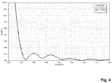
- Figure 4 shows a plot of the VSWR performance of an antenna 1 having these dimensions.
- the relatively wide elliptic surface acts as a mode filter and maintains a stable radiation field without overmodes and notches being introduced at high frequencies, giving a stable omnidirectional radiation pattern.
- the ground plane 20 can be formed as a printed component on a circuit board and may be manufactured in a known way, using etching, deposition, milling or any suitable process.
- the element 10 can be formed as a unitary piece of metal or other conductor and can be formed by a cutting or milling operation. Typically, both ground plane 10 and element 20 are formed from copper.
- the thickness of each element is not typically critical and can vary from the standard thickness of a printed circuit board trace (e.g. 17 ⁇ m, as in 5oz copper) to a few millimetres, if formed from copper sheet.
- the upright element 10 need not be strictly perpendicular to the ground plane 20, but should be substantially normal to it. In use, the element 10 may be mechanically vulnerable unless it can be somehow protected from environmental risks. These risks could include knocks as well as environmental risks from water and the like.
- the entire antenna, except for the connector (not shown) is encapsulated in a foam-like material which protects the antenna and ensures that it remains mechanically sound.
- the foam 30 can be seen surrounding the element 10.
- the foam-like material has suitable RF characteristics, such that it does not unduly interfere with the operation of the antenna 1.
- a suitable material is provided by ROHACELL ® and is known as ROHACELL HF. This is robust, low density and moisture proof as well as having RF characteristics which do not impede the operation of the antenna.
- the foam surround 30 can be shaped as required for both practical and aesthetic purposes.
- the Ultra wideband performance can be extended to lower frequencies. In the prior art, this would typically be achieved by a significant scaling up of the design or by means of dielectric loading. The former can result in an antenna which is significantly larger and often unsuitable, whereas the latter can lose some bandwidth.
- MDM magneto-dielectric material
- a suitable MDM according to an embodiment of the invention is known as Rogers Magtrex 555.
- MDMs are able to achieve this performance by having unusually low loss magnetic permeability which combines with conventional dielectric permittivity. They enable antenna size reduction - or conversely lower frequency operation within a size constraint, without the drawbacks associated with traditional dielectric-only loading of poor match to free space impedance, Zo. They achieve this by exploiting the following general relationships:
- Embodiments of the present invention offer performance across a wide range of frequencies, with the antenna itself being compact and easy to produce.
Landscapes
- Details Of Aerials (AREA)
Abstract
Disclosed is an antenna comprising a substantially elliptical element arranged substantially perpendicular to, and spaced apart from, a substantially elliptical ground plane, wherein the substantially elliptical element has a major axis which is substantially perpendicular to the ground plane, and a minor axis which is substantially parallel to the ground plane.
Description
- The present invention relates to an antenna. It relates particularly to a wideband antenna having a particular arrangement of primary element and ground plane.
- Antennas are essential in Radio Frequency Transmitter, Receivers and Transceivers. There are various forms of antennas, all of which have certain advantages or disadvantages. Much skill is required in the field of antenna design, not least since many of the competing system demands are difficult to reconcile.
- In particular, for handheld or portable equipment, such as a mobile telephone or other such device, it is desirable to provide an antenna which provides suitable performance and which is, at the same time, unobtrusive.
- Since the earliest mobile telephone devices were provided with an extendable whip antenna, users have demanded internal antennas which provide the same or better performance but which are not liable to inadvertent damage. This has led to the used of PIFA or similar antennas.
- A further complication in antenna design is the increasing need to provide antennas which are operable at a suitable performance level across a wide bandwidth. Indeed, the requirement to operate across a large bandwidth has been prompted by developments such as Ultra wideband communications. In this context, Ultra wideband means operable over typically an octave (or more) frequency range.
- A problem in the design of such ultra wideband antennas is reconciling different design constraints and still providing an antenna having acceptable performance across the desired range.
- Embodiments of the present invention aim to address shortcomings in the prior art, whether mentioned herein or not.
- According to the present invention there is provided an apparatus and method as set forth in the appended claims. Other features of the invention will be apparent from the dependent claims, and the description which follows.
- According to the present invention there is provided an antenna comprising a substantially elliptical element arranged substantially perpendicular to, and spaced apart from, a substantially elliptical ground plane, wherein the substantially elliptical element has a major axis which is substantially perpendicular to the ground plane, and a minor axis which is substantially parallel to the ground plane.
- Suitably, the minor axis of the substantially elliptical element is substantially aligned with a major axis of the ground plane.
- Suitably, the major axis of the substantially elliptical element is substantially the same length as the major axis of the elliptical ground plane, and the minor axis of the substantially elliptical element is substantially the same length as a minor axis of the ground plane.
- Suitably, the space between the substantially elliptical element and the ground plane is selected so as to achieve a good impedance match between the substantially elliptical element and the ground plane.
- Suitably, one or both of the substantially elliptical element and the ground plane is coated with a magneto-dielectric material.
- Suitably, the antenna is encapsulated in a material such that the substantially elliptical element and the ground plane are physically shielded.
- Suitably, the antenna is encapsulated in a foam material, such as ROHACELL HF.
- For a better understanding of the invention, and to show how embodiments of the same may be carried into effect, reference will now be made, by way of example, to the accompanying diagrammatic drawings in which:
-
Figure 1 shows a perspective view of an antenna according to an embodiment of the present invention; -
Figure 2 shows a plan view of an antenna according to an embodiment of the present invention; -
Figure 3 shows a side view of an antenna according to an embodiment of the present invention; and -
Figure 4 shows a VSWR plot of an antenna according to an embodiment of the present invention. -
Figure 1 shows a perspective view of anantenna 1 according to an embodiment of the present invention.Figures 2 and3 show plan and side views, respectively. As can be seen, theantenna 1 comprises two main parts: a substantially upright and substantiallyelliptical element 10, mounted in a spaced apart fashion from a substantiallyelliptical ground plane 20. - In the following description, the term elliptical is used to describe the two
parts antenna 1. The term elliptical is qualified by the term substantially to mean strict compliance with the mathematical definition of an ellipse is not required. Instead, the term "Substantially elliptical" should be interpreted to mean a generally oval shape. At one extreme, a circle would not fall within the description and at another extreme, a rectangle with rounded corners would not. For brevity and ease of comprehension, whenever the term "elliptical" is used herein, it is not be interpreted as requiring absolute compliance with the mathematical definition and should be interpreted as "substantially elliptical". - In an embodiment, the
element 10 is mounted atop a feed structure and is separated from theground plane 20 by the feed structure. Theelement 10 is electrically isolated from theground plane 20 by means of a suitable connector, such as a TNC or SMA connector. In this way, an antenna feed cable can be coupled to the connector from a side of the ground plane opposite to the side above whichelement 10 is positioned. This separation also provides a degree of impedance matching. The absolute separation distance is determined on a trial and error basis as will be readily understood by the skilled person. - In a preferred embodiment, the size and shape of
element 10 andground plane 20 are identical. As can be seen inFigures 2 and3 , there are two dimensions defined for each of theparts - In another embodiment, the size and shape do not have to match exactly and it is acceptable for D1 and/or D2 to differ by ±20%. It is found that variation of these dimensions in this range delivers an acceptable level of performance.
- In a preferred embodiment, the ratio of D2: D1 is 2:1. In other embodiments, this can vary by ±20%. It is found that variation of these dimensions in this range delivers an acceptable level of performance.
- In the embodiment shown in
Figures 1 to 3 , D2 is 8cm and D1 is 4cm. An antenna having these dimensions is found to operate acceptably well over thefrequency range 1 to 6GHz. This includes many popular frequency bands used in mobile telecommunication, as well as WiFi and other systems.Figure 4 shows a plot of the VSWR performance of anantenna 1 having these dimensions. - The use of an elliptic shape for a radiating part of an antenna is known, but the combination of an
elliptic element 10 and a correspondingelliptical ground plane 20 is new and offers the benefits set out herein. - In use, the relatively wide elliptic surface acts as a mode filter and maintains a stable radiation field without overmodes and notches being introduced at high frequencies, giving a stable omnidirectional radiation pattern.
- The
ground plane 20 can be formed as a printed component on a circuit board and may be manufactured in a known way, using etching, deposition, milling or any suitable process. Theelement 10 can be formed as a unitary piece of metal or other conductor and can be formed by a cutting or milling operation. Typically, bothground plane 10 andelement 20 are formed from copper. The thickness of each element is not typically critical and can vary from the standard thickness of a printed circuit board trace (e.g. 17µm, as in 5oz copper) to a few millimetres, if formed from copper sheet. - The
upright element 10 need not be strictly perpendicular to theground plane 20, but should be substantially normal to it. In use, theelement 10 may be mechanically vulnerable unless it can be somehow protected from environmental risks. These risks could include knocks as well as environmental risks from water and the like. - In an embodiment, the entire antenna, except for the connector (not shown) is encapsulated in a foam-like material which protects the antenna and ensures that it remains mechanically sound. In
figure 1 , thefoam 30 can be seen surrounding theelement 10. - In a further embodiment, the foam-like material has suitable RF characteristics, such that it does not unduly interfere with the operation of the
antenna 1. A suitable material is provided by ROHACELL ® and is known as ROHACELL HF. This is robust, low density and moisture proof as well as having RF characteristics which do not impede the operation of the antenna. Thefoam surround 30 can be shaped as required for both practical and aesthetic purposes. - The Ultra wideband performance can be extended to lower frequencies. In the prior art, this would typically be achieved by a significant scaling up of the design or by means of dielectric loading. The former can result in an antenna which is significantly larger and often unsuitable, whereas the latter can lose some bandwidth.
- In an embodiment of the present invention, however, it is possible to achieve the benefit of lower frequency operation without substantially altering the dimensions of the antenna by coating the
element 10 andground plane 20 is a magneto-dielectric material (MDM). - In tests conducted on the antenna thus far described, where D2 = 8cm and D1 = 4cm, a 6mm coating of both major antenna parts provides acceptable performance well down into VHF bands. The coating is applied to each side of
element 10 and the upper side ofground plane 20. This has the benefit of further miniaturising embodiments of the present invention. - A suitable MDM according to an embodiment of the invention is known as Rogers Magtrex 555.
- MDMs are able to achieve this performance by having unusually low loss magnetic permeability which combines with conventional dielectric permittivity. They enable antenna size reduction - or conversely lower frequency operation within a size constraint, without the drawbacks associated with traditional dielectric-only loading of poor match to free space impedance, Zo. They achieve this by exploiting the following general relationships:
- Overall Impedance:

- Benefit: Better matched to free space.
- Especially if Ur=Er - a balanced material -
- which can thus improve bandwidth
- Miniaturisation factor

- Benefit: Useful miniaturisation factors can
- be achieved without the use of high Er ceramics etc
- Where Er = Relative Permittivity (or dielectric Constant)
- Ur = Relative Permeability
- And both also need to have low loss tangents to avoid loss of efficiency.
- Whereas if Ur=1 (leaving Er as in a conventional dielectric) it results in less miniaturisation but poorer impedance matching and bandwidth (especially if high Er is used).
- As magneto-dielectric materials are relatively dense, care should be taken to ensure weight constraints are met. In any event, excess thickness of MD may support unwanted rf overmodes or increase losses and should be avoided.
- Embodiments of the present invention offer performance across a wide range of frequencies, with the antenna itself being compact and easy to produce.
- Attention is directed to all papers and documents which are filed concurrently with or previous to this specification in connection with this application and which are open to public inspection with this specification, and the contents of all such papers and documents are incorporated herein by reference.
- All of the features disclosed in this specification (including any accompanying claims, abstract and drawings), and/or all of the steps of any method or process so disclosed, may be combined in any combination, except combinations where at least some of such features and/or steps are mutually exclusive.
- Each feature disclosed in this specification (including any accompanying claims, abstract and drawings) may be replaced by alternative features serving the same, equivalent or similar purpose, unless expressly stated otherwise. Thus, unless expressly stated otherwise, each feature disclosed is one example only of a generic series of equivalent or similar features.
- The invention is not restricted to the details of the foregoing embodiment(s). The invention extends to any novel one, or any novel combination, of the features disclosed in this specification (including any accompanying claims, abstract and drawings), or to any novel one, or any novel combination, of the steps of any method or process so disclosed.
Claims (7)
- An antenna comprising a substantially elliptical element arranged substantially perpendicular to, and spaced apart from, a substantially elliptical ground plane, wherein the substantially elliptical element has a major axis which is substantially perpendicular to the ground plane, and a minor axis which is substantially parallel to the ground plane.
- The antenna of claim 1 wherein the minor axis of the substantially elliptical element is substantially aligned with a major axis of the ground plane.
- The antenna of claim 2 wherein the major axis of the substantially elliptical element is substantially the same length as the major axis of the elliptical ground plane, and the minor axis of the substantially elliptical element is substantially the same length as a minor axis of the ground plane.
- The antenna of any preceding claim wherein the space between the substantially elliptical element and the ground plane is selected so as to achieve a good impedance match between the substantially elliptical element and the ground plane.
- The antenna of any preceding claim wherein one or both of the substantially elliptical element and the ground plane is coated with a magneto-dielectric material.
- The antenna of any preceding claim wherein the antenna is encapsulated in a material such that the substantially elliptical element and the ground plane are physically shielded.
- The antenna of claim 6 wherein the antenna is encapsulated in a foam material, such as ROHACELL HF.
Priority Applications (5)
| Application Number | Priority Date | Filing Date | Title |
|---|---|---|---|
| EP18275157.8A EP3633789A1 (en) | 2018-10-05 | 2018-10-05 | An antenna |
| US17/282,041 US11916318B2 (en) | 2018-10-05 | 2019-09-24 | Antenna |
| ES19779078T ES2999617T3 (en) | 2018-10-05 | 2019-09-24 | An antenna |
| EP19779078.5A EP3861593B8 (en) | 2018-10-05 | 2019-09-24 | An antenna |
| PCT/GB2019/052681 WO2020070471A1 (en) | 2018-10-05 | 2019-09-24 | An antenna |
Applications Claiming Priority (1)
| Application Number | Priority Date | Filing Date | Title |
|---|---|---|---|
| EP18275157.8A EP3633789A1 (en) | 2018-10-05 | 2018-10-05 | An antenna |
Publications (1)
| Publication Number | Publication Date |
|---|---|
| EP3633789A1 true EP3633789A1 (en) | 2020-04-08 |
Family
ID=63794419
Family Applications (1)
| Application Number | Title | Priority Date | Filing Date |
|---|---|---|---|
| EP18275157.8A Ceased EP3633789A1 (en) | 2018-10-05 | 2018-10-05 | An antenna |
Country Status (1)
| Country | Link |
|---|---|
| EP (1) | EP3633789A1 (en) |
Cited By (2)
| Publication number | Priority date | Publication date | Assignee | Title |
|---|---|---|---|---|
| US11616300B1 (en) | 2022-02-15 | 2023-03-28 | Nantenna LLC | Miniature broadband antenna assembly |
| US12113281B2 (en) | 2021-08-06 | 2024-10-08 | Nantenna LLC | Broadband antenna assembly |
Citations (3)
| Publication number | Priority date | Publication date | Assignee | Title |
|---|---|---|---|---|
| WO2004066441A1 (en) * | 2003-01-24 | 2004-08-05 | Yokohama Tlo Company, Ltd. | Wideband antenna |
| US7183978B1 (en) * | 2005-03-07 | 2007-02-27 | Bae Systems Information And Electronic Systems Integration Inc. | Wideband omnidirectional antenna |
| WO2012027006A2 (en) * | 2010-08-23 | 2012-03-01 | Wisconsin Alumni Research Foundation | Ultra-wideband, low profile antenna |
-
2018
- 2018-10-05 EP EP18275157.8A patent/EP3633789A1/en not_active Ceased
Patent Citations (3)
| Publication number | Priority date | Publication date | Assignee | Title |
|---|---|---|---|---|
| WO2004066441A1 (en) * | 2003-01-24 | 2004-08-05 | Yokohama Tlo Company, Ltd. | Wideband antenna |
| US7183978B1 (en) * | 2005-03-07 | 2007-02-27 | Bae Systems Information And Electronic Systems Integration Inc. | Wideband omnidirectional antenna |
| WO2012027006A2 (en) * | 2010-08-23 | 2012-03-01 | Wisconsin Alumni Research Foundation | Ultra-wideband, low profile antenna |
Cited By (2)
| Publication number | Priority date | Publication date | Assignee | Title |
|---|---|---|---|---|
| US12113281B2 (en) | 2021-08-06 | 2024-10-08 | Nantenna LLC | Broadband antenna assembly |
| US11616300B1 (en) | 2022-02-15 | 2023-03-28 | Nantenna LLC | Miniature broadband antenna assembly |
Similar Documents
| Publication | Publication Date | Title |
|---|---|---|
| US6424300B1 (en) | Notch antennas and wireless communicators incorporating same | |
| CN102414914B (en) | Balanced metamaterial antenna device | |
| US6268831B1 (en) | Inverted-f antennas with multiple planar radiating elements and wireless communicators incorporating same | |
| EP1293012B1 (en) | Dual band patch antenna | |
| US9502770B2 (en) | Compact multiple-band antenna for wireless devices | |
| EP2178166B1 (en) | Loop antenna including impedance tuning gap and associated methods | |
| US6229487B1 (en) | Inverted-F antennas having non-linear conductive elements and wireless communicators incorporating the same | |
| Gupta et al. | Dual-band miniature coupled double loop GPS antenna loaded with lumped capacitors and inductive pins | |
| US20190115671A1 (en) | Fractal-rectangular reactive impedance surface for antenna miniaturization | |
| EP2666207B1 (en) | Communications device and tracking device with slotted antenna and related methods | |
| CN202712422U (en) | Ultra wide-band antenna | |
| Nghaimesh et al. | Triple-band circular patch microstrip antenna for wireless communication | |
| US20030103008A1 (en) | In-building low profile antenna | |
| KR20090096914A (en) | Planar folded monopole antenna | |
| Karthika et al. | Design of a novel UWB antenna for wireless applications | |
| EP3861593B1 (en) | An antenna | |
| JPH07288423A (en) | Mobile radio antenna | |
| GB2577740A (en) | An antenna | |
| Tondare et al. | Meander line antenna for LTE communications | |
| Ibrahim et al. | Compact V-shaped MIMO Antenna for LTE and 5G Communications | |
| Thavakumar et al. | Design of multi resonant PIFA antenna for mobile telecommunication networks | |
| Rahim et al. | Design and analysis of ultra wide band planar monopole antenna | |
| Anooz | Bandwidth enhancement by slotted ultra-wide band antenna | |
| Woo et al. | Ultra wide band antenna for true wireless stereo earphones | |
| KR100531624B1 (en) | Ultra WideBand Inverted L Antenna Apparatus |
Legal Events
| Date | Code | Title | Description |
|---|---|---|---|
| PUAI | Public reference made under article 153(3) epc to a published international application that has entered the european phase |
Free format text: ORIGINAL CODE: 0009012 |
|
| AK | Designated contracting states |
Kind code of ref document: A1 Designated state(s): AL AT BE BG CH CY CZ DE DK EE ES FI FR GB GR HR HU IE IS IT LI LT LU LV MC MK MT NL NO PL PT RO RS SE SI SK SM TR |
|
| AX | Request for extension of the european patent |
Extension state: BA ME |
|
| STAA | Information on the status of an ep patent application or granted ep patent |
Free format text: STATUS: THE APPLICATION HAS BEEN REFUSED |
|
| 18R | Application refused |
Effective date: 20200703 |