EP3633777A1 - Equipment management method and equipment management device - Google Patents
Equipment management method and equipment management device Download PDFInfo
- Publication number
- EP3633777A1 EP3633777A1 EP18808945.2A EP18808945A EP3633777A1 EP 3633777 A1 EP3633777 A1 EP 3633777A1 EP 18808945 A EP18808945 A EP 18808945A EP 3633777 A1 EP3633777 A1 EP 3633777A1
- Authority
- EP
- European Patent Office
- Prior art keywords
- fuel cell
- cell system
- state
- equipment management
- equipment
- Prior art date
- Legal status (The legal status is an assumption and is not a legal conclusion. Google has not performed a legal analysis and makes no representation as to the accuracy of the status listed.)
- Granted
Links
Images



Classifications
-
- H—ELECTRICITY
- H01—ELECTRIC ELEMENTS
- H01M—PROCESSES OR MEANS, e.g. BATTERIES, FOR THE DIRECT CONVERSION OF CHEMICAL ENERGY INTO ELECTRICAL ENERGY
- H01M8/00—Fuel cells; Manufacture thereof
- H01M8/04—Auxiliary arrangements, e.g. for control of pressure or for circulation of fluids
- H01M8/04298—Processes for controlling fuel cells or fuel cell systems
- H01M8/04313—Processes for controlling fuel cells or fuel cell systems characterised by the detection or assessment of variables; characterised by the detection or assessment of failure or abnormal function
- H01M8/04664—Failure or abnormal function
-
- G—PHYSICS
- G06—COMPUTING OR CALCULATING; COUNTING
- G06N—COMPUTING ARRANGEMENTS BASED ON SPECIFIC COMPUTATIONAL MODELS
- G06N5/00—Computing arrangements using knowledge-based models
- G06N5/04—Inference or reasoning models
-
- G—PHYSICS
- G06—COMPUTING OR CALCULATING; COUNTING
- G06Q—INFORMATION AND COMMUNICATION TECHNOLOGY [ICT] SPECIALLY ADAPTED FOR ADMINISTRATIVE, COMMERCIAL, FINANCIAL, MANAGERIAL OR SUPERVISORY PURPOSES; SYSTEMS OR METHODS SPECIALLY ADAPTED FOR ADMINISTRATIVE, COMMERCIAL, FINANCIAL, MANAGERIAL OR SUPERVISORY PURPOSES, NOT OTHERWISE PROVIDED FOR
- G06Q10/00—Administration; Management
- G06Q10/20—Administration of product repair or maintenance
-
- H—ELECTRICITY
- H01—ELECTRIC ELEMENTS
- H01M—PROCESSES OR MEANS, e.g. BATTERIES, FOR THE DIRECT CONVERSION OF CHEMICAL ENERGY INTO ELECTRICAL ENERGY
- H01M8/00—Fuel cells; Manufacture thereof
- H01M8/04—Auxiliary arrangements, e.g. for control of pressure or for circulation of fluids
- H01M8/04298—Processes for controlling fuel cells or fuel cell systems
- H01M8/04992—Processes for controlling fuel cells or fuel cell systems characterised by the implementation of mathematical or computational algorithms, e.g. feedback control loops, fuzzy logic, neural networks or artificial intelligence
-
- H—ELECTRICITY
- H02—GENERATION; CONVERSION OR DISTRIBUTION OF ELECTRIC POWER
- H02J—ELECTRIC POWER NETWORKS; CIRCUIT ARRANGEMENTS OR SYSTEMS FOR SUPPLYING OR DISTRIBUTING ELECTRIC POWER; SYSTEMS FOR STORING ELECTRIC ENERGY
- H02J13/00—Circuit arrangements for providing remote monitoring or remote control of equipment in a power distribution network
- H02J13/13—Circuit arrangements for providing remote monitoring or remote control of equipment in a power distribution network characterised by the transmission of data to equipment in the power network
- H02J13/1321—Circuit arrangements for providing remote monitoring or remote control of equipment in a power distribution network characterised by the transmission of data to equipment in the power network using a wired telecommunication network or a data transmission bus
-
- H—ELECTRICITY
- H02—GENERATION; CONVERSION OR DISTRIBUTION OF ELECTRIC POWER
- H02J—ELECTRIC POWER NETWORKS; CIRCUIT ARRANGEMENTS OR SYSTEMS FOR SUPPLYING OR DISTRIBUTING ELECTRIC POWER; SYSTEMS FOR STORING ELECTRIC ENERGY
- H02J3/00—Circuit arrangements for AC mains or AC distribution networks
- H02J3/38—Arrangements for feeding a single network from two or more generators or sources in parallel; Arrangements for feeding already energised networks from additional generators or sources in parallel
- H02J3/381—Dispersed generators
-
- H—ELECTRICITY
- H02—GENERATION; CONVERSION OR DISTRIBUTION OF ELECTRIC POWER
- H02J—ELECTRIC POWER NETWORKS; CIRCUIT ARRANGEMENTS OR SYSTEMS FOR SUPPLYING OR DISTRIBUTING ELECTRIC POWER; SYSTEMS FOR STORING ELECTRIC ENERGY
- H02J13/00—Circuit arrangements for providing remote monitoring or remote control of equipment in a power distribution network
- H02J13/13—Circuit arrangements for providing remote monitoring or remote control of equipment in a power distribution network characterised by the transmission of data to equipment in the power network
- H02J13/1331—Circuit arrangements for providing remote monitoring or remote control of equipment in a power distribution network characterised by the transmission of data to equipment in the power network using wireless data transmission
- H02J13/1333—Circuit arrangements for providing remote monitoring or remote control of equipment in a power distribution network characterised by the transmission of data to equipment in the power network using wireless data transmission by means of mobile telephony
-
- H—ELECTRICITY
- H02—GENERATION; CONVERSION OR DISTRIBUTION OF ELECTRIC POWER
- H02J—ELECTRIC POWER NETWORKS; CIRCUIT ARRANGEMENTS OR SYSTEMS FOR SUPPLYING OR DISTRIBUTING ELECTRIC POWER; SYSTEMS FOR STORING ELECTRIC ENERGY
- H02J2101/00—Supply or distribution of decentralised, dispersed or local electric power generation
- H02J2101/20—Dispersed power generation using renewable energy sources
- H02J2101/30—Fuel cells
-
- H—ELECTRICITY
- H02—GENERATION; CONVERSION OR DISTRIBUTION OF ELECTRIC POWER
- H02J—ELECTRIC POWER NETWORKS; CIRCUIT ARRANGEMENTS OR SYSTEMS FOR SUPPLYING OR DISTRIBUTING ELECTRIC POWER; SYSTEMS FOR STORING ELECTRIC ENERGY
- H02J2103/00—Details of circuit arrangements for mains or AC distribution networks
- H02J2103/30—Simulating, planning, modelling, reliability check or computer assisted design [CAD] of electric power networks
- H02J2103/35—Grid-level management of power transmission or distribution systems, e.g. load flow analysis or active network management
-
- Y—GENERAL TAGGING OF NEW TECHNOLOGICAL DEVELOPMENTS; GENERAL TAGGING OF CROSS-SECTIONAL TECHNOLOGIES SPANNING OVER SEVERAL SECTIONS OF THE IPC; TECHNICAL SUBJECTS COVERED BY FORMER USPC CROSS-REFERENCE ART COLLECTIONS [XRACs] AND DIGESTS
- Y02—TECHNOLOGIES OR APPLICATIONS FOR MITIGATION OR ADAPTATION AGAINST CLIMATE CHANGE
- Y02E—REDUCTION OF GREENHOUSE GAS [GHG] EMISSIONS, RELATED TO ENERGY GENERATION, TRANSMISSION OR DISTRIBUTION
- Y02E40/00—Technologies for an efficient electrical power generation, transmission or distribution
- Y02E40/70—Smart grids as climate change mitigation technology in the energy generation sector
-
- Y—GENERAL TAGGING OF NEW TECHNOLOGICAL DEVELOPMENTS; GENERAL TAGGING OF CROSS-SECTIONAL TECHNOLOGIES SPANNING OVER SEVERAL SECTIONS OF THE IPC; TECHNICAL SUBJECTS COVERED BY FORMER USPC CROSS-REFERENCE ART COLLECTIONS [XRACs] AND DIGESTS
- Y02—TECHNOLOGIES OR APPLICATIONS FOR MITIGATION OR ADAPTATION AGAINST CLIMATE CHANGE
- Y02E—REDUCTION OF GREENHOUSE GAS [GHG] EMISSIONS, RELATED TO ENERGY GENERATION, TRANSMISSION OR DISTRIBUTION
- Y02E60/00—Enabling technologies; Technologies with a potential or indirect contribution to GHG emissions mitigation
-
- Y—GENERAL TAGGING OF NEW TECHNOLOGICAL DEVELOPMENTS; GENERAL TAGGING OF CROSS-SECTIONAL TECHNOLOGIES SPANNING OVER SEVERAL SECTIONS OF THE IPC; TECHNICAL SUBJECTS COVERED BY FORMER USPC CROSS-REFERENCE ART COLLECTIONS [XRACs] AND DIGESTS
- Y02—TECHNOLOGIES OR APPLICATIONS FOR MITIGATION OR ADAPTATION AGAINST CLIMATE CHANGE
- Y02E—REDUCTION OF GREENHOUSE GAS [GHG] EMISSIONS, RELATED TO ENERGY GENERATION, TRANSMISSION OR DISTRIBUTION
- Y02E60/00—Enabling technologies; Technologies with a potential or indirect contribution to GHG emissions mitigation
- Y02E60/30—Hydrogen technology
- Y02E60/50—Fuel cells
-
- Y—GENERAL TAGGING OF NEW TECHNOLOGICAL DEVELOPMENTS; GENERAL TAGGING OF CROSS-SECTIONAL TECHNOLOGIES SPANNING OVER SEVERAL SECTIONS OF THE IPC; TECHNICAL SUBJECTS COVERED BY FORMER USPC CROSS-REFERENCE ART COLLECTIONS [XRACs] AND DIGESTS
- Y04—INFORMATION OR COMMUNICATION TECHNOLOGIES HAVING AN IMPACT ON OTHER TECHNOLOGY AREAS
- Y04S—SYSTEMS INTEGRATING TECHNOLOGIES RELATED TO POWER NETWORK OPERATION, COMMUNICATION OR INFORMATION TECHNOLOGIES FOR IMPROVING THE ELECTRICAL POWER GENERATION, TRANSMISSION, DISTRIBUTION, MANAGEMENT OR USAGE, i.e. SMART GRIDS
- Y04S10/00—Systems supporting electrical power generation, transmission or distribution
- Y04S10/12—Monitoring or controlling equipment for energy generation units, e.g. distributed energy generation [DER] or load-side generation
-
- Y—GENERAL TAGGING OF NEW TECHNOLOGICAL DEVELOPMENTS; GENERAL TAGGING OF CROSS-SECTIONAL TECHNOLOGIES SPANNING OVER SEVERAL SECTIONS OF THE IPC; TECHNICAL SUBJECTS COVERED BY FORMER USPC CROSS-REFERENCE ART COLLECTIONS [XRACs] AND DIGESTS
- Y04—INFORMATION OR COMMUNICATION TECHNOLOGIES HAVING AN IMPACT ON OTHER TECHNOLOGY AREAS
- Y04S—SYSTEMS INTEGRATING TECHNOLOGIES RELATED TO POWER NETWORK OPERATION, COMMUNICATION OR INFORMATION TECHNOLOGIES FOR IMPROVING THE ELECTRICAL POWER GENERATION, TRANSMISSION, DISTRIBUTION, MANAGEMENT OR USAGE, i.e. SMART GRIDS
- Y04S10/00—Systems supporting electrical power generation, transmission or distribution
- Y04S10/50—Systems or methods supporting the power network operation or management, involving a certain degree of interaction with the load-side end user applications
-
- Y—GENERAL TAGGING OF NEW TECHNOLOGICAL DEVELOPMENTS; GENERAL TAGGING OF CROSS-SECTIONAL TECHNOLOGIES SPANNING OVER SEVERAL SECTIONS OF THE IPC; TECHNICAL SUBJECTS COVERED BY FORMER USPC CROSS-REFERENCE ART COLLECTIONS [XRACs] AND DIGESTS
- Y04—INFORMATION OR COMMUNICATION TECHNOLOGIES HAVING AN IMPACT ON OTHER TECHNOLOGY AREAS
- Y04S—SYSTEMS INTEGRATING TECHNOLOGIES RELATED TO POWER NETWORK OPERATION, COMMUNICATION OR INFORMATION TECHNOLOGIES FOR IMPROVING THE ELECTRICAL POWER GENERATION, TRANSMISSION, DISTRIBUTION, MANAGEMENT OR USAGE, i.e. SMART GRIDS
- Y04S40/00—Systems for electrical power generation, transmission, distribution or end-user application management characterised by the use of communication or information technologies, or communication or information technology specific aspects supporting them
- Y04S40/12—Systems for electrical power generation, transmission, distribution or end-user application management characterised by the use of communication or information technologies, or communication or information technology specific aspects supporting them characterised by data transport means between the monitoring, controlling or managing units and monitored, controlled or operated electrical equipment
- Y04S40/124—Systems for electrical power generation, transmission, distribution or end-user application management characterised by the use of communication or information technologies, or communication or information technology specific aspects supporting them characterised by data transport means between the monitoring, controlling or managing units and monitored, controlled or operated electrical equipment using wired telecommunication networks or data transmission busses
-
- Y—GENERAL TAGGING OF NEW TECHNOLOGICAL DEVELOPMENTS; GENERAL TAGGING OF CROSS-SECTIONAL TECHNOLOGIES SPANNING OVER SEVERAL SECTIONS OF THE IPC; TECHNICAL SUBJECTS COVERED BY FORMER USPC CROSS-REFERENCE ART COLLECTIONS [XRACs] AND DIGESTS
- Y04—INFORMATION OR COMMUNICATION TECHNOLOGIES HAVING AN IMPACT ON OTHER TECHNOLOGY AREAS
- Y04S—SYSTEMS INTEGRATING TECHNOLOGIES RELATED TO POWER NETWORK OPERATION, COMMUNICATION OR INFORMATION TECHNOLOGIES FOR IMPROVING THE ELECTRICAL POWER GENERATION, TRANSMISSION, DISTRIBUTION, MANAGEMENT OR USAGE, i.e. SMART GRIDS
- Y04S40/00—Systems for electrical power generation, transmission, distribution or end-user application management characterised by the use of communication or information technologies, or communication or information technology specific aspects supporting them
- Y04S40/12—Systems for electrical power generation, transmission, distribution or end-user application management characterised by the use of communication or information technologies, or communication or information technology specific aspects supporting them characterised by data transport means between the monitoring, controlling or managing units and monitored, controlled or operated electrical equipment
- Y04S40/126—Systems for electrical power generation, transmission, distribution or end-user application management characterised by the use of communication or information technologies, or communication or information technology specific aspects supporting them characterised by data transport means between the monitoring, controlling or managing units and monitored, controlled or operated electrical equipment using wireless data transmission
Definitions
- the present invention relates to an equipment management method and an equipment management apparatus.
- the various pieces of information include basic information on equipment and maintenance information.
- the basic information includes, for example, an installation date, a predetermined service life, a rated power consumption, and the like.
- the maintenance information includes a history of past maintenance (for example, Patent Literature 1).
- Patent Literature 1 Japanese application publication No. 2005-182399
- An equipment management method comprises a step A of receiving, from a fuel cell system to an equipment management apparatus, a state message including an information element indicating a state of the fuel cell system; and a step B of transmitting, from the equipment management apparatus to a predetermined terminal, a notification message based on the state message, wherein the notification message includes an information element for specifying a recommended time for which maintenance of the fuel cell system is recommended to be executed.
- An equipment management apparatus comprises a receiver configured to receive, from the fuel cell system, a state message including an information element indicating a state of a fuel cell system; and a transmitter configured to transmit a notification message based on the state message, wherein the notification message includes an information element for specifying a recommended time for which maintenance of the fuel cell system is recommended to be executed.
- equipment managed by the equipment management system is a fuel cell system
- the fuel cell system has a high temperature at a time point at which an abnormality of the equipment is detected.
- a situation where the vendor cannot perform maintenance of the fuel cell system until the temperature of the fuel cell system decreases can be considered.
- a disclosure indicated below describes an equipment management method and an equipment management apparatus that enable maintenance of a fuel cell system to be performed efficiently in order to solve the above-described problem.
- an equipment management system 100 includes an equipment management apparatus 200, a facility 300, and a predetermined terminal 400.
- Fig. 1 exemplifies facilities 300A to 300C as the facility 300.
- the equipment management apparatus 200 and the facility 300 are connected to a network 120.
- the network 120 may provide a line between the equipment management apparatus 200 and the facility 300, and a line between the equipment management apparatus 200 and the predetermined terminal 400.
- the network 120 is, for example, the Internet.
- a dedicated line such as a VPN, may be provided.
- the equipment management apparatus 200 manages equipment provided in the facility 300. Details of the equipment management apparatus 200 will be described later (see Fig. 3 ).
- the facility 300 has a fuel cell system 310 and an EMS 320.
- the fuel cell system 310 includes equipment that generates power using fuel, such as gas. Details of the fuel cell system 310 will be described later (see Fig. 2 ).
- the EMS 320 is equipment (energy management system) that controls equipment provided in the facility 300.
- the facility 300 may have load equipment that consumes power.
- the load equipment is, for example, air conditioning equipment, lighting equipment, audio visual (AV) equipment, and the like.
- the facility 300 may have a distributed power supply other than the fuel cell system 310.
- the distributed power supply may include, for example, equipment that generates power using natural energy, such as solar light, wind power, geothermal energy, and may include storage battery equipment.
- the predetermined terminal 400 may be a terminal held by a manager who manages equipment provided in the facility 300.
- the predetermined terminal 400 may be a terminal held by a worker who performs maintenance of equipment provided in the facility 300.
- the predetermined terminal 400 may be a terminal belonging to a company, such as a power generation company, a power transmission and distribution company, a retailer.
- the predetermined terminal 400 may be a smartphone, a tablet terminal, or a personal computer.
- the equipment management system 100 may have a power management server.
- the power management server transmits, for example, a power flow control message requesting control of a power flow amount from a power grid 110 to the facility 300, a reverse power flow control message requesting control of a reverse power flow amount from the facility 300 to the power grid 110, a power control message requesting control of the fuel cell system 310 (distributed power supply) provided in the facility 300, and the like to the facility 300.
- Fig. 2 is a diagram illustrating the fuel cell system 310 according to the embodiment.
- the fuel cell system 310 includes at least fuel cell equipment 150.
- the fuel cell system 310 may include hot water storage equipment 160.
- the fuel cell system 310 will be described as being a cogeneration system including both the fuel cell equipment 150 and the hot water storage equipment 160.
- the fuel cell equipment 150 is equipment that generates power using fuel, such as gas.
- the hot water storage equipment 160 is equipment that generates hot water or maintains a water temperature using fuel, such as gas. Specifically, the hot water storage equipment 160 has a hot water storage tank, warms water supplied from the hot water storage tank by heat generated by combustion of fuel or exhaust heat generated by power generation of the fuel cell equipment 150, and returns the warmed water to the hot water storage tank.
- the fuel cell equipment 150 has a fuel cell 151, a PCS 152, a blower 153, a desulfurizer 154, an ignition heater 155, a radiator 156, and a control substrate 157.
- the fuel cell 151 is equipment that generates power using fuel. Specifically, the fuel cell 151 includes a reformer 151A and a cell stack 151B.
- the reformer 151A generates reformed gas from fuel from which an odorant is removed by the desulfurizer 154 described later.
- the reformed gas is a gas including hydrogen and carbon monoxide.
- the cell stack 151B generates power by a chemical reaction between air (oxygen) supplied from the blower 153 described later and the reformed gas.
- the cell stack 151B has a structure in which a plurality of cells is stacked. Each cell has a structure in which an electrolyte is sandwiched between a fuel electrode and an air electrode.
- the reformed gas (hydrogen) is supplied to the fuel electrode, and air (oxygen) is supplied to the air electrode.
- a chemical reaction of the reformed gas (hydrogen) and the air (oxygen) occurs in the electrolyte to generate power (DC power) and heat.
- the PCS 152 is equipment (power conditioning system) that converts DC power output from the fuel cell 151 into AC power.
- the blower 153 supplies air to the fuel cell 151 (cell stack 151B).
- the blower 153 is configured with, for example, a fan.
- the blower 153 cools the cell stack 151B so that a temperature of the cell stack 151B does not exceed an upper limit of an allowable temperature.
- the desulfurizer 154 removes the odorant contained in fuel supplied from the outside.
- the fuel may be city gas or propane gas.
- the ignition heater 155 is a heater that ignites fuel (hereinafter, unreacted fuel) that does not react chemically in the cell stack 151B and maintains the temperature of the cell stack 151B at a high temperature. That is, the ignition heater 155 ignites unreacted fuel leaking from an opening of each cell constituting the cell stack 151B. It should be noted that the ignition heater 155 preferably ignites unreacted fuel in a case where the unreacted fuel is not combusted (for example, at the time of starting the fuel cell equipment 150). Then, after the combustion of the unreacted gas starts, the temperature of the cell stack 151B is maintained at a high temperature as the combustion of the unreacted fuel which overflows slightly from the cell stack 151B continues.
- fuel hereinafter, unreacted fuel
- the radiator 156 cools water (hereinafter, reflux water) flowing from the hot water storage equipment 160 to the fuel cell equipment 150, so that a temperature of the reflux water does not exceed an upper limit of an allowable temperature.
- the radiator 156 may also cool the cell stack 151B so that the temperature of the cell stack 151B does not exceed an upper limit of an allowable temperature.
- the control substrate 157 is a substrate, on which a circuit for controlling the fuel cell 151, the PCS 152, the blower 153, the desulfurizer 154, the ignition heater 155, and the control substrate 157 is mounted.
- the reformer 151A, the blower 153, the desulfurizer 154, the ignition heater 155, and the control substrate 157 are an example of auxiliaries that assist operation of the cell stack 151B. Further, part of the PCS 152 may be treated as auxiliaries.
- An operating state of the fuel cell system 310 includes a power generation state (also referred to as during power generation), a stop state (also referred to as during stoppage), a start state (also referred to as during start), a stopping operation state (also referred to as during stopping operation), an idle state (also referred to as during idling), and the like.
- the power generation state is a state in which power generation is performed by the fuel cell 151.
- the start state is a state from the stop state to the power generation state.
- the stop state is a state in which operation of the fuel cell 151 is stopped.
- the stopping operation state is a state from the power generation state to the stop state.
- the idle state is a state in which power is not output from the fuel cell system 310, but the temperature of the cell stack 151B is maintained at a predetermined temperature.
- the predetermined temperature may be approximately the same as a power generation temperature (for example, 650°C to 1000°C) of the cell stack 151B in the power generation state, and may be a temperature (for example, 450°C to 600°C) lower than the power generation temperature.
- power of the auxiliaries may be covered by power output from the fuel cell 151, may be covered by power supplied from another distributed power supply (for example, equipment or storage battery equipment that generates power using natural energy), or may be covered by power supplied from the power grid 110.
- another distributed power supply for example, equipment or storage battery equipment that generates power using natural energy
- control substrate 157 is provided in the fuel cell equipment 150.
- the fuel cell system 310 may include a remote controller that receives user operation, and the control substrate 157 may be provided in a remote controller.
- a function of the control substrate 157 may be realized by both the substrate provided in the fuel cell equipment 150 and the remote controller.
- the equipment management apparatus 200 includes a manager 210, a communicator 220, and a controller 230.
- the manager 210 is configured with a storage medium, such as a non-volatile memory and/or an HDD, and manages information on a plurality of the facilities 300.
- a storage medium such as a non-volatile memory and/or an HDD
- the manager 210 may store basic information of equipment provided in each of a plurality of the facilities 300.
- the manager 210 stores a facility name, a facility ID, an equipment name, an equipment ID, an introduction year, aging, and a useful life by associating them with each other.
- the facility name is a name of the facility 300 where the equipment is installed.
- the facility ID is an identifier for identifying the facility 300.
- the equipment name is a name of equipment.
- the equipment ID is an identifier for identifying equipment.
- the introduction year is a year in which equipment is introduced.
- the aging indicates years that have passed since introduction of equipment.
- the useful life is determined by a manufacturer of equipment, and the like, and is information indicating a period in which equipment can be used appropriately after the equipment is introduced.
- the manager 210 may store, for each of a plurality of the facilities 300, maintenance information of equipment provided in each of a plurality of the facilities 300.
- the manager 210 stores a facility name, an equipment name, a maintenance date, a maintenance outline, and a maintenance detail by associating them with each other.
- the manager 210 may store a facility ID and an equipment ID by associating them with each other together with these pieces of information.
- the facility name and the equipment name are as described above.
- the maintenance date is a date on which maintenance is performed.
- the maintenance outline is information indicating an outline of maintenance
- the maintenance detail is information indicating the details of maintenance.
- the maintenance information according to the embodiment preferably includes at least a maintenance period (planned) for performing maintenance of equipment in the future.
- the maintenance information may include a maintenance period in which maintenance of equipment is performed in the past.
- the maintenance includes, for example, an inspection for examining a deterioration state of equipment, maintenance for performing minor maintenance at the time of inspection, a repair for dealing with a failure of equipment, replacement for replacing existing equipment with new equipment, and the like.
- an inspection for examining a deterioration state of equipment for performing minor maintenance at the time of inspection
- a repair for dealing with a failure of equipment for replacing existing equipment with new equipment, and the like.
- the maintenance is a repair or replacement will be mainly described.
- the manager 210 may manage information indicating a temperature environment of the fuel cell system 310.
- Information indicating a temperature environment may include at least any one of parameters of a temperature (indoor temperature, outdoor temperature) at an installation location of the fuel cell system 310, a weather at the installation location of the fuel cell system 310, a wind speed at the installation location of the fuel cell system 310, an amount of solar radiation at the installation location of the fuel cell system 310.
- a temperature, a wind speed, and an amount of solar radiation may be acquired from an external server, such as a weather server.
- the manager 210 may manage information indicating an installation environment of the fuel cell system 310.
- the information indicating an installation environment may include at least any one of a parameter indicating that the installation location of the fuel cell system 310 is outdoor, a parameter indicating that the installation location of the fuel cell system 310 is indoor, a parameter indicating that the installation location of the fuel cell system 310 is on a lower floor (for example, a first floor), and a parameter indicating that the installation location of the fuel cell system 310 is on an upper floor (for example, a roof).
- the communicator 220 is configured with a communication module, and communicates with the facility 300 and the predetermined terminal 400 via the network 120.
- the communicator 220 constitutes a receiver that receives a state message including an information element indicating a state of the fuel cell system 310.
- the communicator 220 may receive the state message from the fuel cell system 310 via the EMS 320, and may receive the state message from the fuel cell system 310 without the EMS 320.
- the communicator 220 constitutes a transmitter that transmits a notification message including an information element for specifying recommended time for which execution of maintenance of the fuel cell system 310 is recommended to the predetermined terminal 400.
- the information element for specifying the recommended time is an information element indicating a recommended time specified by the controller 230 described later.
- the state message may include an information element indicating a type (hereinafter, the stop operation type) of stopping operation by which the fuel cell system 310 is stopped.
- the stop operation type is, for example, normal stop and shutdown.
- the normal stop is operation, in which although the power generation by the fuel cell 151 is stopped, the blower 153 or the radiator 156 is not stopped, and the operation of the fuel cell system 310 is stopped while the temperature of the cell stack 151B is lowered using the blower 153 or the radiator 156.
- the shutdown is operation of stopping not only the power generation by the fuel cell 151, but also the entire operation of the fuel cell system 310.
- the operation of the normal stop is, for example, operation executed in response to a relatively minor abnormality (hereinafter, referred to as a first abnormality) or operation executed in periodic maintenance of the fuel cell system 310.
- the operation of the shutdown is, for example, operation that is executed in response to a relatively serious abnormality (hereinafter, referred to as a second abnormality), or operation that is executed in a state where the normal stop cannot be performed.
- the second abnormality is a more serious abnormality than the first abnormality.
- the state message may include an information element indicating a type (hereinafter referred to as the operation state type) of an operating state of the fuel cell system 310 at the time of occurrence of an abnormality.
- the operation state type is, for example, a power generation state, a stop state, a start state, a stop operation state, an idle state, or the like.
- the state message may include an information element indicating an abnormal part of the fuel cell system 310 in which the abnormality has occurred.
- a part of the fuel cell system 310 is, for example, a part (the cell stack 151B, the blower 153) illustrated in Fig. 2 .
- a part of the fuel cell system 310 may include the hot water storage equipment 160 and may include a remote controller.
- the state message may include two or more information elements selected from an information element indicating the stop operation type, an information element indicating the operation state type, and an information element indicating an abnormal part.
- the state message may include an information element indicating a temperature environment, and may include an information element indicating an installation environment.
- the information element indicating a temperature environment may include an information element indicating the temperature of the cell stack 151.
- the information element indicating an installation environment may include an information element indicating an outside air temperature.
- the controller 230 is configured with a memory, a CPU, and the like, and controls each component provided in the equipment management apparatus 200.
- the controller 230 specifies recommended time for which execution of the maintenance of the fuel cell system 310 is recommended based on the state message.
- the recommended time does not include time when maintenance cannot be performed due to a temperature of the fuel cell system 310.
- the controller 230 specifies time after a timing at which the temperature of the fuel cell system 310 falls below a predetermined temperature as the recommended time.
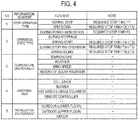
- the controller 230 may specify the recommended time based on the stop operation type as illustrated in No. 1 of Fig. 4 . This is because the time from the start of the stop operation to the completion of the stop operation (hereinafter referred to as the required stop time) varies depending on the stop operation type, and a speed at which the temperature of the fuel cell system 310 decreases varies depending on the stop operation type. Specifically, since a cooling effect by the blower 153 or the radiator 156 cannot be expected in the shutdown, a stop time T2 associated with the shutdown is longer than a stop time T1 associated with the normal stop. Therefore, the controller 230 specifies time later than the recommended time corresponding to the normal stop as the recommended time corresponding to the shutdown. The recommended time corresponding to the shutdown may overlap with part of the recommended time corresponding to the normal stop.
- the controller 230 may specify the recommended time based on the operation state type, as illustrated in No. 2 of Fig. 4 . This is because the temperature of the fuel cell system 310 at the start of the stopping operation differs depending on the operation state. Specifically, the temperature of the fuel cell system 310 in the start state or the stop operation state is lower than the temperature of the fuel cell system 310 in the power generation state. That is, a stop time T4 corresponding to the start state or a stop time T5 corresponding to the stop operation state is shorter than a stop time T3 corresponding to the power generation state. Therefore, the controller 230 specifies time before the recommended time corresponding to the power generation state as the recommended time corresponding to the start state or the stop operation state.
- the recommended time corresponding to the start state or the stop operation state may overlap with the recommended time corresponding to the power generation state.
- the temperature of the fuel cell system 310 in the idle state is less than or equal to the temperature of the fuel cell system 310 in the power generation state. That is, a stop time T6 corresponding to the idle state is equal to or less than the stop time T3 corresponding to the power generation state. Therefore, the controller 230 specifies, as the recommended time corresponding to the idle state, time similar to the recommended time corresponding to the power generation state or time earlier than the recommended time corresponding to the power generation state.
- the recommended time corresponding to the idle state may overlap with the recommended time corresponding to the power generation state.
- the controller 230 may specify the recommended time based on the temperature environment of the fuel cell system 310, as illustrated in No. 3 of Fig. 4 . This is because a rate at which the temperature of the fuel cell system 310 decreases varies depending on the temperature environment.
- the controller 230 may specify the recommended time based on an abnormal part as illustrated in No. 4 of Fig. 4 . This is because a temperature of an abnormal part at the time of starting the stop operation is different for each abnormal part. Specifically, the temperature of the cell stack 151B is the highest, and a temperature of a part is lower as the part is disposed at a position farther from the cell stack 151B. For example, the controller 230 specifies time earlier than the recommended time corresponding to the cell stack 151B as the recommended time corresponding to the hot water storage equipment 160 or the remote controller. Part of the recommended time corresponding to the hot water storage equipment 160 or the remote controller may overlap with the recommended time corresponding to the cell stack 151B.
- the controller 230 may specify the recommended time based on an installation environment of the fuel cell system 310, as illustrated in No. 5 of Fig. 4 . This is because a rate at which the temperature of the fuel cell system 310 decreases varies depending on the installation environment.
- the controller 230 may specify the recommended time based on two or more information elements selected from among the stop operation type, the operation state type, the temperature environment, the abnormal part, and the installation environment.
- the controller 230 may specify the recommended time based on a normal part. For example, in a case where it is possible to specify whether or not all parts are normal, a part other than the normal part is an abnormal part.
- the state message may be transmitted via the EMS 320.
- the fuel cell system 310 transmits the state message to the equipment management apparatus 200.
- the state message may include at least any one of an information element indicating the stop operation type, an information element indicating the operation state type, and an information element indicating an abnormal part.
- Step S12 the equipment management apparatus 200 specifies the recommended time based on the state message.
- the method of specifying the recommended time is as described above (see Fig. 4 and the like).
- the recommended time is specified according to the reception of the state message, so that the specification of the recommended time is based on the state message.
- Step S13 the equipment management apparatus 200 transmits, to the predetermined terminal 400, a notification message including an information element for identifying the recommended time.
- the equipment management apparatus 200 specifies the recommended time based on the state message, and transmits a notification message including the recommended time to the predetermined terminal 400. According to such a configuration, since the notification message includes the recommended time, it is possible to reduce the time for a vendor who performs maintenance to wait until the temperature of the fuel cell system 310 decreases, and the maintenance of the fuel cell system 310 can be performed efficiently.
- the manager 210 is provided in the equipment management apparatus 200, but the embodiment is not limited to this.
- the manager 210 may be provided in a server connected to the equipment management apparatus 200 via the network 120.
- the state message may include an information element indicating the operation state type.
- the state message may include an information element indicating a start time of an operation state corresponding to the operation state type.
- the state message may include an information element indicating the start time of the start state, and may include an information element indicating the start time of the stop operation state.
- the temperature of the fuel cell system 310 can be estimated based on the time elapsed from the start time, and the specification accuracy of the recommended time is improved.
- the state message may include an information element indicating a time at which an abnormality of the fuel cell system 310 occurs.
- the fuel cell system 310 transmits the state message to the equipment management apparatus 200 when the operation of the fuel cell system 310 is stopped.
- the fuel cell system 310 may transmit the state message to the equipment management apparatus 200 when it is predicted that the operation of the fuel cell system 310 is to be stopped before the operation of the fuel cell system 310 is stopped.
- the stop operation type is a type of the stop operation for stopping according to an abnormality predicted by the fuel cell system 310
- the operation state type is a type of the operation state of the fuel cell system 310 assumed at the time an abnormality predicted by the fuel cell system 310 occurs
- the abnormal part is a part where an abnormality predicted by the fuel cell system 310 is assumed to occur.
- the information element for specifying the recommended time is an information element indicating the recommended time.
- the information element for specifying the recommended time may be an information element indicating the above-described required stop time. This is because the recommended time can be specified by the required stop time.
- the information element for specifying the recommended time may be the information element illustrated in Fig. 4 (at least any one of information element of the stop operation type, the stop operation state, the temperature environment, the abnormal part, and the installation environment). This is because the recommended time can be specified by these information elements.
- At least either one of the recommended time and the required stop time can be specified based on the information element illustrated in Fig. 4 .
- the embodiment is not limited to the above.
- At least either one of the recommended time and the required stop time may be predicted based on an abnormality history of the fuel cell system 310 in the past. In such prediction, the information element illustrated in Fig. 4 may be referred to.
- At least any one of the equipment management apparatus 200, the fuel cell system 310, and the predetermined terminal 400 may have a display for displaying various messages.
- the various messages are, for example, the state message and the notification message described above.
- the fuel cell equipment 150 is a solid oxide fuel cell (SOFC). However, the fuel cell equipment 150 may be a polymer electrolyte fuel cell (PEFC), a phosphoric acid fuel cell (PAFC), or a molten carbonate fuel cell (MCFC).
- PEFC polymer electrolyte fuel cell
- PAFC phosphoric acid fuel cell
- MCFC molten carbonate fuel cell
Landscapes
- Engineering & Computer Science (AREA)
- Theoretical Computer Science (AREA)
- Business, Economics & Management (AREA)
- Human Resources & Organizations (AREA)
- General Physics & Mathematics (AREA)
- Physics & Mathematics (AREA)
- Artificial Intelligence (AREA)
- Computing Systems (AREA)
- Evolutionary Computation (AREA)
- Software Systems (AREA)
- General Chemical & Material Sciences (AREA)
- Life Sciences & Earth Sciences (AREA)
- Manufacturing & Machinery (AREA)
- Sustainable Development (AREA)
- Sustainable Energy (AREA)
- Chemical & Material Sciences (AREA)
- Chemical Kinetics & Catalysis (AREA)
- Electrochemistry (AREA)
- Marketing (AREA)
- Tourism & Hospitality (AREA)
- Automation & Control Theory (AREA)
- Economics (AREA)
- Entrepreneurship & Innovation (AREA)
- Medical Informatics (AREA)
- Operations Research (AREA)
- Quality & Reliability (AREA)
- Strategic Management (AREA)
- Fuzzy Systems (AREA)
- Health & Medical Sciences (AREA)
- General Business, Economics & Management (AREA)
- Power Engineering (AREA)
- Fuel Cell (AREA)
- Computational Linguistics (AREA)
- Data Mining & Analysis (AREA)
- General Engineering & Computer Science (AREA)
- Mathematical Physics (AREA)
- Remote Monitoring And Control Of Power-Distribution Networks (AREA)
- Supply And Distribution Of Alternating Current (AREA)
Abstract
Description
- The present invention relates to an equipment management method and an equipment management apparatus.
- An equipment management system that manages various pieces of information on a plurality of pieces of equipment is known. The various pieces of information include basic information on equipment and maintenance information. The basic information includes, for example, an installation date, a predetermined service life, a rated power consumption, and the like. The maintenance information includes a history of past maintenance (for example, Patent Literature 1).
- Patent Literature 1: Japanese application publication No.
2005-182399 - An equipment management method according to a first disclosure comprises a step A of receiving, from a fuel cell system to an equipment management apparatus, a state message including an information element indicating a state of the fuel cell system; and a step B of transmitting, from the equipment management apparatus to a predetermined terminal, a notification message based on the state message, wherein the notification message includes an information element for specifying a recommended time for which maintenance of the fuel cell system is recommended to be executed.
- An equipment management apparatus according to a second disclosure comprises a receiver configured to receive, from the fuel cell system, a state message including an information element indicating a state of a fuel cell system; and a transmitter configured to transmit a notification message based on the state message, wherein the notification message includes an information element for specifying a recommended time for which maintenance of the fuel cell system is recommended to be executed.
-
-
Fig. 1 is a diagram illustrating anequipment management system 100 according to an embodiment. -
Fig. 2 is a diagram illustrating afuel cell system 310 according to the embodiment. -
Fig. 3 is a diagram illustrating anequipment management apparatus 200 according to the embodiment. -
Fig. 4 is a diagram for explaining specification of recommended time according to the embodiment. -
Fig. 5 is a diagram illustrating an equipment management method according to the embodiment. - Hereinafter, an embodiment will be described. Note that, in description of the drawings below, the same or similar sections are attached with the same or similar reference signs. However, it should be noted that the drawings are schematic drawings, and a ratio of each dimension and the like may be different from actual ones.
- Accordingly, a specific dimension and the like need to be determined in consideration of the description below. Further, between mutual drawings, there may also be a case where sections have dimensions that are different from each other in relationships or ratios as a matter of course.
- In recent years, an attempt has been made to arrange a vendor who performs equipment maintenance when equipment abnormality is detected using the above-described equipment management system.
- For example, in a case where equipment managed by the equipment management system is a fuel cell system, a case where the fuel cell system has a high temperature at a time point at which an abnormality of the equipment is detected. In such a case, even if a vendor is arranged when an abnormality of the equipment is detected, a situation where the vendor cannot perform maintenance of the fuel cell system until the temperature of the fuel cell system decreases can be considered.
- A disclosure indicated below describes an equipment management method and an equipment management apparatus that enable maintenance of a fuel cell system to be performed efficiently in order to solve the above-described problem.
- Hereinafter, an equipment management system according to an embodiment will be described. As illustrated in
Fig. 1 , anequipment management system 100 includes anequipment management apparatus 200, afacility 300, and apredetermined terminal 400.Fig. 1 exemplifiesfacilities 300A to 300C as thefacility 300. Theequipment management apparatus 200 and thefacility 300 are connected to anetwork 120. Thenetwork 120 may provide a line between theequipment management apparatus 200 and thefacility 300, and a line between theequipment management apparatus 200 and thepredetermined terminal 400. Thenetwork 120 is, for example, the Internet. As thenetwork 120, a dedicated line, such as a VPN, may be provided. - The
equipment management apparatus 200 manages equipment provided in thefacility 300. Details of theequipment management apparatus 200 will be described later (seeFig. 3 ). - The
facility 300 has afuel cell system 310 and an EMS 320. Thefuel cell system 310 includes equipment that generates power using fuel, such as gas. Details of thefuel cell system 310 will be described later (seeFig. 2 ). The EMS 320 is equipment (energy management system) that controls equipment provided in thefacility 300. - The
facility 300 may have load equipment that consumes power. The load equipment is, for example, air conditioning equipment, lighting equipment, audio visual (AV) equipment, and the like. Thefacility 300 may have a distributed power supply other than thefuel cell system 310. The distributed power supply may include, for example, equipment that generates power using natural energy, such as solar light, wind power, geothermal energy, and may include storage battery equipment. - The
predetermined terminal 400 may be a terminal held by a manager who manages equipment provided in thefacility 300. Thepredetermined terminal 400 may be a terminal held by a worker who performs maintenance of equipment provided in thefacility 300. Thepredetermined terminal 400 may be a terminal belonging to a company, such as a power generation company, a power transmission and distribution company, a retailer. Thepredetermined terminal 400 may be a smartphone, a tablet terminal, or a personal computer. - Here, the
equipment management system 100 may have a power management server. The power management server transmits, for example, a power flow control message requesting control of a power flow amount from apower grid 110 to thefacility 300, a reverse power flow control message requesting control of a reverse power flow amount from thefacility 300 to thepower grid 110, a power control message requesting control of the fuel cell system 310 (distributed power supply) provided in thefacility 300, and the like to thefacility 300. - Hereinafter, a fuel cell system according to the embodiment will be described.
Fig. 2 is a diagram illustrating thefuel cell system 310 according to the embodiment. Thefuel cell system 310 includes at leastfuel cell equipment 150. Thefuel cell system 310 may include hotwater storage equipment 160. Here, thefuel cell system 310 will be described as being a cogeneration system including both thefuel cell equipment 150 and the hotwater storage equipment 160. - The
fuel cell equipment 150 is equipment that generates power using fuel, such as gas. The hotwater storage equipment 160 is equipment that generates hot water or maintains a water temperature using fuel, such as gas. Specifically, the hotwater storage equipment 160 has a hot water storage tank, warms water supplied from the hot water storage tank by heat generated by combustion of fuel or exhaust heat generated by power generation of thefuel cell equipment 150, and returns the warmed water to the hot water storage tank. - As illustrated in
Fig. 2 , thefuel cell equipment 150 has afuel cell 151, a PCS 152, ablower 153, adesulfurizer 154, anignition heater 155, aradiator 156, and acontrol substrate 157. - The
fuel cell 151 is equipment that generates power using fuel. Specifically, thefuel cell 151 includes areformer 151A and acell stack 151B. - The
reformer 151A generates reformed gas from fuel from which an odorant is removed by thedesulfurizer 154 described later. The reformed gas is a gas including hydrogen and carbon monoxide. - The
cell stack 151B generates power by a chemical reaction between air (oxygen) supplied from theblower 153 described later and the reformed gas. Specifically, thecell stack 151B has a structure in which a plurality of cells is stacked. Each cell has a structure in which an electrolyte is sandwiched between a fuel electrode and an air electrode. The reformed gas (hydrogen) is supplied to the fuel electrode, and air (oxygen) is supplied to the air electrode. A chemical reaction of the reformed gas (hydrogen) and the air (oxygen) occurs in the electrolyte to generate power (DC power) and heat. - The
PCS 152 is equipment (power conditioning system) that converts DC power output from thefuel cell 151 into AC power. - The
blower 153 supplies air to the fuel cell 151 (cell stack 151B). Theblower 153 is configured with, for example, a fan. Theblower 153 cools thecell stack 151B so that a temperature of thecell stack 151B does not exceed an upper limit of an allowable temperature. - The
desulfurizer 154 removes the odorant contained in fuel supplied from the outside. The fuel may be city gas or propane gas. - The
ignition heater 155 is a heater that ignites fuel (hereinafter, unreacted fuel) that does not react chemically in thecell stack 151B and maintains the temperature of thecell stack 151B at a high temperature. That is, theignition heater 155 ignites unreacted fuel leaking from an opening of each cell constituting thecell stack 151B. It should be noted that theignition heater 155 preferably ignites unreacted fuel in a case where the unreacted fuel is not combusted (for example, at the time of starting the fuel cell equipment 150). Then, after the combustion of the unreacted gas starts, the temperature of thecell stack 151B is maintained at a high temperature as the combustion of the unreacted fuel which overflows slightly from thecell stack 151B continues. - The
radiator 156 cools water (hereinafter, reflux water) flowing from the hotwater storage equipment 160 to thefuel cell equipment 150, so that a temperature of the reflux water does not exceed an upper limit of an allowable temperature. Theradiator 156 may also cool thecell stack 151B so that the temperature of thecell stack 151B does not exceed an upper limit of an allowable temperature. - The
control substrate 157 is a substrate, on which a circuit for controlling thefuel cell 151, thePCS 152, theblower 153, thedesulfurizer 154, theignition heater 155, and thecontrol substrate 157 is mounted. - The
reformer 151A, theblower 153, thedesulfurizer 154, theignition heater 155, and thecontrol substrate 157 are an example of auxiliaries that assist operation of thecell stack 151B. Further, part of thePCS 152 may be treated as auxiliaries. - An operating state of the
fuel cell system 310 includes a power generation state (also referred to as during power generation), a stop state (also referred to as during stoppage), a start state (also referred to as during start), a stopping operation state (also referred to as during stopping operation), an idle state (also referred to as during idling), and the like. - The power generation state is a state in which power generation is performed by the
fuel cell 151. The start state is a state from the stop state to the power generation state. The stop state is a state in which operation of thefuel cell 151 is stopped. The stopping operation state is a state from the power generation state to the stop state. The idle state is a state in which power is not output from thefuel cell system 310, but the temperature of thecell stack 151B is maintained at a predetermined temperature. The predetermined temperature may be approximately the same as a power generation temperature (for example, 650°C to 1000°C) of thecell stack 151B in the power generation state, and may be a temperature (for example, 450°C to 600°C) lower than the power generation temperature. In the idle state, power of the auxiliaries may be covered by power output from thefuel cell 151, may be covered by power supplied from another distributed power supply (for example, equipment or storage battery equipment that generates power using natural energy), or may be covered by power supplied from thepower grid 110. - In the example illustrated in
Fig. 2 , thecontrol substrate 157 is provided in thefuel cell equipment 150. However, the embodiment is not limited to the above. Thefuel cell system 310 may include a remote controller that receives user operation, and thecontrol substrate 157 may be provided in a remote controller. Alternatively, a function of thecontrol substrate 157 may be realized by both the substrate provided in thefuel cell equipment 150 and the remote controller. - Hereinafter, an equipment management apparatus according to the embodiment will be described. As illustrated in
Fig. 3 , theequipment management apparatus 200 includes amanager 210, acommunicator 220, and acontroller 230. - The
manager 210 is configured with a storage medium, such as a non-volatile memory and/or an HDD, and manages information on a plurality of thefacilities 300. - The
manager 210 may store basic information of equipment provided in each of a plurality of thefacilities 300. For example, themanager 210 stores a facility name, a facility ID, an equipment name, an equipment ID, an introduction year, aging, and a useful life by associating them with each other. The facility name is a name of thefacility 300 where the equipment is installed. The facility ID is an identifier for identifying thefacility 300. The equipment name is a name of equipment. The equipment ID is an identifier for identifying equipment. The introduction year is a year in which equipment is introduced. The aging indicates years that have passed since introduction of equipment. The useful life is determined by a manufacturer of equipment, and the like, and is information indicating a period in which equipment can be used appropriately after the equipment is introduced. - The
manager 210 may store, for each of a plurality of thefacilities 300, maintenance information of equipment provided in each of a plurality of thefacilities 300. For example, themanager 210 stores a facility name, an equipment name, a maintenance date, a maintenance outline, and a maintenance detail by associating them with each other. Themanager 210 may store a facility ID and an equipment ID by associating them with each other together with these pieces of information. The facility name and the equipment name are as described above. The maintenance date is a date on which maintenance is performed. The maintenance outline is information indicating an outline of maintenance, and the maintenance detail is information indicating the details of maintenance. The maintenance information according to the embodiment preferably includes at least a maintenance period (planned) for performing maintenance of equipment in the future. The maintenance information may include a maintenance period in which maintenance of equipment is performed in the past. - Here, the maintenance includes, for example, an inspection for examining a deterioration state of equipment, maintenance for performing minor maintenance at the time of inspection, a repair for dealing with a failure of equipment, replacement for replacing existing equipment with new equipment, and the like. Hereinafter, a case where the maintenance is a repair or replacement will be mainly described.
- In the embodiment, the
manager 210 may manage information indicating a temperature environment of thefuel cell system 310. Information indicating a temperature environment may include at least any one of parameters of a temperature (indoor temperature, outdoor temperature) at an installation location of thefuel cell system 310, a weather at the installation location of thefuel cell system 310, a wind speed at the installation location of thefuel cell system 310, an amount of solar radiation at the installation location of thefuel cell system 310. A temperature, a wind speed, and an amount of solar radiation may be acquired from an external server, such as a weather server. - The
manager 210 may manage information indicating an installation environment of thefuel cell system 310. The information indicating an installation environment may include at least any one of a parameter indicating that the installation location of thefuel cell system 310 is outdoor, a parameter indicating that the installation location of thefuel cell system 310 is indoor, a parameter indicating that the installation location of thefuel cell system 310 is on a lower floor (for example, a first floor), and a parameter indicating that the installation location of thefuel cell system 310 is on an upper floor (for example, a roof). - The
communicator 220 is configured with a communication module, and communicates with thefacility 300 and thepredetermined terminal 400 via thenetwork 120. Thecommunicator 220 constitutes a receiver that receives a state message including an information element indicating a state of thefuel cell system 310. Thecommunicator 220 may receive the state message from thefuel cell system 310 via theEMS 320, and may receive the state message from thefuel cell system 310 without theEMS 320. Thecommunicator 220 constitutes a transmitter that transmits a notification message including an information element for specifying recommended time for which execution of maintenance of thefuel cell system 310 is recommended to thepredetermined terminal 400. The information element for specifying the recommended time is an information element indicating a recommended time specified by thecontroller 230 described later. - Here, the state message may include an information element indicating a type (hereinafter, the stop operation type) of stopping operation by which the
fuel cell system 310 is stopped. The stop operation type is, for example, normal stop and shutdown. The normal stop is operation, in which although the power generation by thefuel cell 151 is stopped, theblower 153 or theradiator 156 is not stopped, and the operation of thefuel cell system 310 is stopped while the temperature of thecell stack 151B is lowered using theblower 153 or theradiator 156. On the other hand, the shutdown is operation of stopping not only the power generation by thefuel cell 151, but also the entire operation of thefuel cell system 310. The operation of the normal stop is, for example, operation executed in response to a relatively minor abnormality (hereinafter, referred to as a first abnormality) or operation executed in periodic maintenance of thefuel cell system 310. On the other hand, the operation of the shutdown is, for example, operation that is executed in response to a relatively serious abnormality (hereinafter, referred to as a second abnormality), or operation that is executed in a state where the normal stop cannot be performed. The second abnormality is a more serious abnormality than the first abnormality. - The state message may include an information element indicating a type (hereinafter referred to as the operation state type) of an operating state of the
fuel cell system 310 at the time of occurrence of an abnormality. The operation state type is, for example, a power generation state, a stop state, a start state, a stop operation state, an idle state, or the like. - The state message may include an information element indicating an abnormal part of the
fuel cell system 310 in which the abnormality has occurred. A part of thefuel cell system 310 is, for example, a part (thecell stack 151B, the blower 153) illustrated inFig. 2 . A part of thefuel cell system 310 may include the hotwater storage equipment 160 and may include a remote controller. - The state message may include two or more information elements selected from an information element indicating the stop operation type, an information element indicating the operation state type, and an information element indicating an abnormal part.
- The state message may include an information element indicating a temperature environment, and may include an information element indicating an installation environment. The information element indicating a temperature environment may include an information element indicating the temperature of the
cell stack 151. The information element indicating an installation environment may include an information element indicating an outside air temperature. - The
controller 230 is configured with a memory, a CPU, and the like, and controls each component provided in theequipment management apparatus 200. In the embodiment, thecontroller 230 specifies recommended time for which execution of the maintenance of thefuel cell system 310 is recommended based on the state message. Here, the recommended time does not include time when maintenance cannot be performed due to a temperature of thefuel cell system 310. For example, thecontroller 230 specifies time after a timing at which the temperature of thefuel cell system 310 falls below a predetermined temperature as the recommended time. - The
controller 230 may specify the recommended time based on the stop operation type as illustrated in No. 1 ofFig. 4 . This is because the time from the start of the stop operation to the completion of the stop operation (hereinafter referred to as the required stop time) varies depending on the stop operation type, and a speed at which the temperature of thefuel cell system 310 decreases varies depending on the stop operation type. Specifically, since a cooling effect by theblower 153 or theradiator 156 cannot be expected in the shutdown, a stop time T2 associated with the shutdown is longer than a stop time T1 associated with the normal stop. Therefore, thecontroller 230 specifies time later than the recommended time corresponding to the normal stop as the recommended time corresponding to the shutdown. The recommended time corresponding to the shutdown may overlap with part of the recommended time corresponding to the normal stop. - The
controller 230 may specify the recommended time based on the operation state type, as illustrated in No. 2 ofFig. 4 . This is because the temperature of thefuel cell system 310 at the start of the stopping operation differs depending on the operation state. Specifically, the temperature of thefuel cell system 310 in the start state or the stop operation state is lower than the temperature of thefuel cell system 310 in the power generation state. That is, a stop time T4 corresponding to the start state or a stop time T5 corresponding to the stop operation state is shorter than a stop time T3 corresponding to the power generation state. Therefore, thecontroller 230 specifies time before the recommended time corresponding to the power generation state as the recommended time corresponding to the start state or the stop operation state. The recommended time corresponding to the start state or the stop operation state may overlap with the recommended time corresponding to the power generation state. The temperature of thefuel cell system 310 in the idle state is less than or equal to the temperature of thefuel cell system 310 in the power generation state. That is, a stop time T6 corresponding to the idle state is equal to or less than the stop time T3 corresponding to the power generation state. Therefore, thecontroller 230 specifies, as the recommended time corresponding to the idle state, time similar to the recommended time corresponding to the power generation state or time earlier than the recommended time corresponding to the power generation state. The recommended time corresponding to the idle state may overlap with the recommended time corresponding to the power generation state. - The
controller 230 may specify the recommended time based on the temperature environment of thefuel cell system 310, as illustrated in No. 3 ofFig. 4 . This is because a rate at which the temperature of thefuel cell system 310 decreases varies depending on the temperature environment. - The
controller 230 may specify the recommended time based on an abnormal part as illustrated in No. 4 ofFig. 4 . This is because a temperature of an abnormal part at the time of starting the stop operation is different for each abnormal part. Specifically, the temperature of thecell stack 151B is the highest, and a temperature of a part is lower as the part is disposed at a position farther from thecell stack 151B. For example, thecontroller 230 specifies time earlier than the recommended time corresponding to thecell stack 151B as the recommended time corresponding to the hotwater storage equipment 160 or the remote controller. Part of the recommended time corresponding to the hotwater storage equipment 160 or the remote controller may overlap with the recommended time corresponding to thecell stack 151B. - The
controller 230 may specify the recommended time based on an installation environment of thefuel cell system 310, as illustrated in No. 5 ofFig. 4 . This is because a rate at which the temperature of thefuel cell system 310 decreases varies depending on the installation environment. - Here, the
controller 230 may specify the recommended time based on two or more information elements selected from among the stop operation type, the operation state type, the temperature environment, the abnormal part, and the installation environment. - Furthermore, the
controller 230 may specify the recommended time based on a normal part. For example, in a case where it is possible to specify whether or not all parts are normal, a part other than the normal part is an abnormal part. - Hereinafter, an equipment management method according to the embodiment will be described. In
Fig. 5 , although theEMS 320 is omitted, the state message may be transmitted via theEMS 320. - As illustrated in
Fig. 5 , in Step S11, thefuel cell system 310 transmits the state message to theequipment management apparatus 200. The state message may include at least any one of an information element indicating the stop operation type, an information element indicating the operation state type, and an information element indicating an abnormal part. - In Step S12, the
equipment management apparatus 200 specifies the recommended time based on the state message. The method of specifying the recommended time is as described above (seeFig. 4 and the like). Here, even in a case where the information element included in the state message is not referred to in the specification of the recommended time, the recommended time is specified according to the reception of the state message, so that the specification of the recommended time is based on the state message. - In Step S13, the
equipment management apparatus 200 transmits, to thepredetermined terminal 400, a notification message including an information element for identifying the recommended time. - In the embodiment, the
equipment management apparatus 200 specifies the recommended time based on the state message, and transmits a notification message including the recommended time to thepredetermined terminal 400. According to such a configuration, since the notification message includes the recommended time, it is possible to reduce the time for a vendor who performs maintenance to wait until the temperature of thefuel cell system 310 decreases, and the maintenance of thefuel cell system 310 can be performed efficiently. - The present invention has been described based on the embodiment described above. However, a statement and the drawings constituting part of the disclosure should not be understood as limiting the present invention. This disclosure will clarify a variety of alternative embodiments, examples, and operation techniques for a person skilled in the art.
- In the embodiment, the
manager 210 is provided in theequipment management apparatus 200, but the embodiment is not limited to this. For example, themanager 210 may be provided in a server connected to theequipment management apparatus 200 via thenetwork 120. - As described in the embodiment, the state message may include an information element indicating the operation state type. In such a case, the state message may include an information element indicating a start time of an operation state corresponding to the operation state type. For example, the state message may include an information element indicating the start time of the start state, and may include an information element indicating the start time of the stop operation state. According to such a configuration, the temperature of the
fuel cell system 310 can be estimated based on the time elapsed from the start time, and the specification accuracy of the recommended time is improved. - Although not particularly mentioned in the embodiment, the state message may include an information element indicating a time at which an abnormality of the
fuel cell system 310 occurs. - In the embodiment, the
fuel cell system 310 transmits the state message to theequipment management apparatus 200 when the operation of thefuel cell system 310 is stopped. However, the embodiment is not limited to the above. Thefuel cell system 310 may transmit the state message to theequipment management apparatus 200 when it is predicted that the operation of thefuel cell system 310 is to be stopped before the operation of thefuel cell system 310 is stopped. In such a case, the stop operation type is a type of the stop operation for stopping according to an abnormality predicted by thefuel cell system 310, the operation state type is a type of the operation state of thefuel cell system 310 assumed at the time an abnormality predicted by thefuel cell system 310 occurs, and the abnormal part is a part where an abnormality predicted by thefuel cell system 310 is assumed to occur. - In the embodiment, the information element for specifying the recommended time is an information element indicating the recommended time. However, the embodiment is not limited to the above. The information element for specifying the recommended time may be an information element indicating the above-described required stop time. This is because the recommended time can be specified by the required stop time. The information element for specifying the recommended time may be the information element illustrated in
Fig. 4 (at least any one of information element of the stop operation type, the stop operation state, the temperature environment, the abnormal part, and the installation environment). This is because the recommended time can be specified by these information elements. - In the embodiment, at least either one of the recommended time and the required stop time can be specified based on the information element illustrated in
Fig. 4 . However, the embodiment is not limited to the above. At least either one of the recommended time and the required stop time may be predicted based on an abnormality history of thefuel cell system 310 in the past. In such prediction, the information element illustrated inFig. 4 may be referred to. - At least any one of the
equipment management apparatus 200, thefuel cell system 310, and thepredetermined terminal 400 may have a display for displaying various messages. The various messages are, for example, the state message and the notification message described above. - The
fuel cell equipment 150 is a solid oxide fuel cell (SOFC). However, thefuel cell equipment 150 may be a polymer electrolyte fuel cell (PEFC), a phosphoric acid fuel cell (PAFC), or a molten carbonate fuel cell (MCFC). - Note that an entire content of Japanese Patent Application No.
2017-106299 (filed on May 30, 2017
Claims (9)
- An equipment management method comprising:a step A of receiving, from a fuel cell system to an equipment management apparatus, a state message including an information element indicating a state of the fuel cell system; anda step B of transmitting, from the equipment management apparatus to a predetermined terminal, a notification message based on the state message, wherein the notification message includes an information element for specifying a recommended time for which maintenance of the fuel cell system is recommended to be executed.
- The equipment management method according to claim 1, further comprising:
a step C of specifying, at the equipment management apparatus, the recommended time based on the state message. - The equipment management method according to claim 2, wherein
the step A includes a step of receiving the state message including an information element indicating a type of stop operation in which the fuel cell system is stopped,
the step C includes a step of specifying the recommended time based on the type of the stop operation. - The equipment management method according to claim 2 or 3, wherein
the step A includes a step of receiving the state message including an information element indicating a type of an operation state of the fuel cell system at a time point at which an abnormality of the fuel cell system occurs, and
the step C includes a step of specifying the recommended time based on the type of the operation state. - The equipment management method according to any of claims 2 to 4, wherein
the step C includes a step of specifying the recommended time based on a temperature environment of the fuel cell system at a time point at which an abnormality of the fuel cell system occurs. - The equipment management method according to any of claims 2 to 5, wherein
the step A includes a step of receiving the state message including an information element indicating an abnormal part of the fuel cell system in which an abnormality of the fuel cell system occurs, and
the step C includes a step of specifying the recommended time based on the abnormal part. - The equipment management method according to any of claims 2 to 6, wherein
the step C includes a step of specifying the recommended time based on an installation environment of the fuel cell system. - The equipment management method according to any of claims 2 to 7, wherein
the step C includes a step of specifying a time as the recommended time, wherein the time is a time after a timing at which a temperature of the fuel cell system falls below a predetermined temperature. - An equipment management apparatus comprising:a receiver configured to receive, from the fuel cell system, a state message including an information element indicating a state of a fuel cell system; anda transmitter configured to transmit a notification message based on the state message, wherein the notification message includes an information element for specifying a recommended time for which maintenance of the fuel cell system is recommended to be executed.
Applications Claiming Priority (2)
| Application Number | Priority Date | Filing Date | Title |
|---|---|---|---|
| JP2017106299 | 2017-05-30 | ||
| PCT/JP2018/020755 WO2018221582A1 (en) | 2017-05-30 | 2018-05-30 | Equipment management method and equipment management device |
Publications (3)
| Publication Number | Publication Date |
|---|---|
| EP3633777A1 true EP3633777A1 (en) | 2020-04-08 |
| EP3633777A4 EP3633777A4 (en) | 2021-02-24 |
| EP3633777B1 EP3633777B1 (en) | 2023-08-30 |
Family
ID=64455444
Family Applications (1)
| Application Number | Title | Priority Date | Filing Date |
|---|---|---|---|
| EP18808945.2A Active EP3633777B1 (en) | 2017-05-30 | 2018-05-30 | Equipment management method and equipment management device |
Country Status (4)
| Country | Link |
|---|---|
| US (1) | US20200160197A1 (en) |
| EP (1) | EP3633777B1 (en) |
| JP (2) | JP6750113B2 (en) |
| WO (1) | WO2018221582A1 (en) |
Families Citing this family (3)
| Publication number | Priority date | Publication date | Assignee | Title |
|---|---|---|---|---|
| JP2021158018A (en) * | 2020-03-27 | 2021-10-07 | 東京瓦斯株式会社 | Management system |
| US20250030248A1 (en) * | 2021-11-26 | 2025-01-23 | Kyocera Corporation | Power system and control method |
| JP7730736B2 (en) * | 2021-12-01 | 2025-08-28 | 京セラ株式会社 | Information processing device, distributed power supply management system, information processing method, and program |
Family Cites Families (25)
| Publication number | Priority date | Publication date | Assignee | Title |
|---|---|---|---|---|
| US7024335B1 (en) * | 1998-04-15 | 2006-04-04 | The Texas A&M University System | Condition assessment and life expectancy prediction for devices |
| JP3799217B2 (en) * | 2000-06-22 | 2006-07-19 | 株式会社日立製作所 | Power generation facility operation management system and maintenance management service method |
| JP2002324566A (en) * | 2001-04-25 | 2002-11-08 | Sanyo Electric Co Ltd | Distributed power-generating system, and maintenance system and method utilizing it |
| JP2003223917A (en) * | 2002-01-30 | 2003-08-08 | Mitsubishi Heavy Ind Ltd | Cogeneration-plant operation support system and operation supporting method |
| US7250231B2 (en) * | 2003-06-09 | 2007-07-31 | Idatech, Llc | Auxiliary fuel cell system |
| EP1542302B1 (en) * | 2003-11-18 | 2012-05-23 | Panasonic Corporation | Fuel cell life predicting device and fuel cell system |
| JP2005182399A (en) | 2003-12-18 | 2005-07-07 | Silis:Kk | Store chart management system |
| JP4610958B2 (en) * | 2004-07-21 | 2011-01-12 | 株式会社日立製作所 | FUEL CELL DEVICE AND FUEL CELL MANAGEMENT SYSTEM |
| JP2006073427A (en) * | 2004-09-03 | 2006-03-16 | Nissan Motor Co Ltd | Fuel cell system |
| JP5157163B2 (en) * | 2006-12-27 | 2013-03-06 | トヨタ自動車株式会社 | FUEL CELL SYSTEM AND FUEL CELL SYSTEM MOUNTING BODY |
| US10410145B2 (en) * | 2007-05-15 | 2019-09-10 | Fisher-Rosemount Systems, Inc. | Automatic maintenance estimation in a plant environment |
| CN101919097B (en) * | 2008-11-20 | 2014-04-09 | 松下电器产业株式会社 | Fuel cell system |
| US20120173299A1 (en) * | 2011-01-04 | 2012-07-05 | Mcmullin Dale Robert | Systems and methods for use in correcting a predicted failure in a production process |
| JP5357287B2 (en) * | 2011-03-23 | 2013-12-04 | パナソニック株式会社 | Fuel cell power generator |
| JP2013164956A (en) * | 2012-02-10 | 2013-08-22 | Jx Nippon Oil & Energy Corp | Solid state oxide fuel cell system, and system stopping method upon failure of cell temperature sensor |
| JP2013218861A (en) * | 2012-04-09 | 2013-10-24 | Toto Ltd | Solid oxide fuel cell |
| JP5911366B2 (en) * | 2012-04-23 | 2016-04-27 | 大阪瓦斯株式会社 | Fuel cell system and control method thereof |
| WO2015122097A1 (en) * | 2014-02-17 | 2015-08-20 | 日産自動車株式会社 | Fuel cell system and control method for fuel cell system |
| CA2942284A1 (en) * | 2014-03-11 | 2015-09-17 | British Gas Trading Limited | Determination of a state of operation of a domestic appliance |
| JP6222044B2 (en) * | 2014-11-07 | 2017-11-01 | トヨタ自動車株式会社 | Residual water scavenging method and fuel cell system in fuel cell system |
| MY181893A (en) * | 2015-04-07 | 2021-01-12 | Tlv Co Ltd | Maintenance support system and maintenance support method |
| JP6183416B2 (en) * | 2015-06-26 | 2017-08-23 | トヨタ自動車株式会社 | Fuel cell system |
| EP3153654B1 (en) | 2015-10-09 | 2019-04-24 | Sandvik Mining and Construction Oy | Rock drilling rig |
| KR101822245B1 (en) * | 2015-12-14 | 2018-01-26 | 현대자동차주식회사 | Control method of cooling pump for fuel cell system |
| US10367215B2 (en) * | 2016-05-23 | 2019-07-30 | Bloom Energy Corporation | Fuel cell system with variable auxiliary bus voltage and method of operating thereof |
-
2018
- 2018-05-30 EP EP18808945.2A patent/EP3633777B1/en active Active
- 2018-05-30 US US16/618,109 patent/US20200160197A1/en not_active Abandoned
- 2018-05-30 WO PCT/JP2018/020755 patent/WO2018221582A1/en not_active Ceased
- 2018-05-30 JP JP2019521269A patent/JP6750113B2/en active Active
-
2020
- 2020-08-12 JP JP2020136500A patent/JP7004778B2/en active Active
Also Published As
| Publication number | Publication date |
|---|---|
| EP3633777B1 (en) | 2023-08-30 |
| JPWO2018221582A1 (en) | 2020-03-26 |
| JP6750113B2 (en) | 2020-09-02 |
| EP3633777A4 (en) | 2021-02-24 |
| JP7004778B2 (en) | 2022-02-04 |
| JP2020205261A (en) | 2020-12-24 |
| WO2018221582A1 (en) | 2018-12-06 |
| US20200160197A1 (en) | 2020-05-21 |
Similar Documents
| Publication | Publication Date | Title |
|---|---|---|
| JP7678043B2 (en) | Fuel cell system, facility management method, management device, and facility management system | |
| JP7004778B2 (en) | Equipment management method and equipment management equipment | |
| JP2025081777A (en) | Fuel cell system and equipment management method | |
| JP7392084B2 (en) | Equipment management method and equipment management device | |
| CN112352336B (en) | Power management server, power management system and power management method | |
| US11557777B2 (en) | Fuel cell system, equipment management method, management apparatus, and equipment management system | |
| JP6088699B2 (en) | Power management system, power management method, power control device, and fuel cell device |
Legal Events
| Date | Code | Title | Description |
|---|---|---|---|
| STAA | Information on the status of an ep patent application or granted ep patent |
Free format text: STATUS: THE INTERNATIONAL PUBLICATION HAS BEEN MADE |
|
| PUAI | Public reference made under article 153(3) epc to a published international application that has entered the european phase |
Free format text: ORIGINAL CODE: 0009012 |
|
| STAA | Information on the status of an ep patent application or granted ep patent |
Free format text: STATUS: REQUEST FOR EXAMINATION WAS MADE |
|
| 17P | Request for examination filed |
Effective date: 20191122 |
|
| AK | Designated contracting states |
Kind code of ref document: A1 Designated state(s): AL AT BE BG CH CY CZ DE DK EE ES FI FR GB GR HR HU IE IS IT LI LT LU LV MC MK MT NL NO PL PT RO RS SE SI SK SM TR |
|
| AX | Request for extension of the european patent |
Extension state: BA ME |
|
| DAV | Request for validation of the european patent (deleted) | ||
| DAX | Request for extension of the european patent (deleted) | ||
| A4 | Supplementary search report drawn up and despatched |
Effective date: 20210126 |
|
| RIC1 | Information provided on ipc code assigned before grant |
Ipc: H01M 8/04 20160101AFI20210120BHEP Ipc: H01M 8/04992 20160101ALI20210120BHEP Ipc: H01M 8/04664 20160101ALI20210120BHEP Ipc: H01M 8/00 20160101ALI20210120BHEP Ipc: G06Q 10/00 20120101ALI20210120BHEP Ipc: H02J 3/38 20060101ALI20210120BHEP Ipc: H01M 8/10 20160101ALI20210120BHEP Ipc: H02J 13/00 20060101ALI20210120BHEP Ipc: H01M 8/12 20160101ALI20210120BHEP |
|
| GRAP | Despatch of communication of intention to grant a patent |
Free format text: ORIGINAL CODE: EPIDOSNIGR1 |
|
| STAA | Information on the status of an ep patent application or granted ep patent |
Free format text: STATUS: GRANT OF PATENT IS INTENDED |
|
| INTG | Intention to grant announced |
Effective date: 20230323 |
|
| P01 | Opt-out of the competence of the unified patent court (upc) registered |
Effective date: 20230505 |
|
| GRAS | Grant fee paid |
Free format text: ORIGINAL CODE: EPIDOSNIGR3 |
|
| GRAA | (expected) grant |
Free format text: ORIGINAL CODE: 0009210 |
|
| STAA | Information on the status of an ep patent application or granted ep patent |
Free format text: STATUS: THE PATENT HAS BEEN GRANTED |
|
| RAP3 | Party data changed (applicant data changed or rights of an application transferred) |
Owner name: KYOCERA CORPORATION |
|
| AK | Designated contracting states |
Kind code of ref document: B1 Designated state(s): AL AT BE BG CH CY CZ DE DK EE ES FI FR GB GR HR HU IE IS IT LI LT LU LV MC MK MT NL NO PL PT RO RS SE SI SK SM TR |
|
| REG | Reference to a national code |
Ref country code: GB Ref legal event code: FG4D |
|
| REG | Reference to a national code |
Ref country code: CH Ref legal event code: EP |
|
| REG | Reference to a national code |
Ref country code: DE Ref legal event code: R096 Ref document number: 602018056548 Country of ref document: DE |
|
| REG | Reference to a national code |
Ref country code: IE Ref legal event code: FG4D |
|
| REG | Reference to a national code |
Ref country code: LT Ref legal event code: MG9D |
|
| REG | Reference to a national code |
Ref country code: NL Ref legal event code: MP Effective date: 20230830 |
|
| REG | Reference to a national code |
Ref country code: AT Ref legal event code: MK05 Ref document number: 1606593 Country of ref document: AT Kind code of ref document: T Effective date: 20230830 |
|
| PG25 | Lapsed in a contracting state [announced via postgrant information from national office to epo] |
Ref country code: GR Free format text: LAPSE BECAUSE OF FAILURE TO SUBMIT A TRANSLATION OF THE DESCRIPTION OR TO PAY THE FEE WITHIN THE PRESCRIBED TIME-LIMIT Effective date: 20231201 |
|
| PG25 | Lapsed in a contracting state [announced via postgrant information from national office to epo] |
Ref country code: IS Free format text: LAPSE BECAUSE OF FAILURE TO SUBMIT A TRANSLATION OF THE DESCRIPTION OR TO PAY THE FEE WITHIN THE PRESCRIBED TIME-LIMIT Effective date: 20231230 |
|
| PG25 | Lapsed in a contracting state [announced via postgrant information from national office to epo] |
Ref country code: SE Free format text: LAPSE BECAUSE OF FAILURE TO SUBMIT A TRANSLATION OF THE DESCRIPTION OR TO PAY THE FEE WITHIN THE PRESCRIBED TIME-LIMIT Effective date: 20230830 Ref country code: RS Free format text: LAPSE BECAUSE OF FAILURE TO SUBMIT A TRANSLATION OF THE DESCRIPTION OR TO PAY THE FEE WITHIN THE PRESCRIBED TIME-LIMIT Effective date: 20230830 Ref country code: NO Free format text: LAPSE BECAUSE OF FAILURE TO SUBMIT A TRANSLATION OF THE DESCRIPTION OR TO PAY THE FEE WITHIN THE PRESCRIBED TIME-LIMIT Effective date: 20231130 Ref country code: LV Free format text: LAPSE BECAUSE OF FAILURE TO SUBMIT A TRANSLATION OF THE DESCRIPTION OR TO PAY THE FEE WITHIN THE PRESCRIBED TIME-LIMIT Effective date: 20230830 Ref country code: LT Free format text: LAPSE BECAUSE OF FAILURE TO SUBMIT A TRANSLATION OF THE DESCRIPTION OR TO PAY THE FEE WITHIN THE PRESCRIBED TIME-LIMIT Effective date: 20230830 Ref country code: IS Free format text: LAPSE BECAUSE OF FAILURE TO SUBMIT A TRANSLATION OF THE DESCRIPTION OR TO PAY THE FEE WITHIN THE PRESCRIBED TIME-LIMIT Effective date: 20231230 Ref country code: HR Free format text: LAPSE BECAUSE OF FAILURE TO SUBMIT A TRANSLATION OF THE DESCRIPTION OR TO PAY THE FEE WITHIN THE PRESCRIBED TIME-LIMIT Effective date: 20230830 Ref country code: GR Free format text: LAPSE BECAUSE OF FAILURE TO SUBMIT A TRANSLATION OF THE DESCRIPTION OR TO PAY THE FEE WITHIN THE PRESCRIBED TIME-LIMIT Effective date: 20231201 Ref country code: FI Free format text: LAPSE BECAUSE OF FAILURE TO SUBMIT A TRANSLATION OF THE DESCRIPTION OR TO PAY THE FEE WITHIN THE PRESCRIBED TIME-LIMIT Effective date: 20230830 Ref country code: AT Free format text: LAPSE BECAUSE OF FAILURE TO SUBMIT A TRANSLATION OF THE DESCRIPTION OR TO PAY THE FEE WITHIN THE PRESCRIBED TIME-LIMIT Effective date: 20230830 |
|
| PG25 | Lapsed in a contracting state [announced via postgrant information from national office to epo] |
Ref country code: PL Free format text: LAPSE BECAUSE OF FAILURE TO SUBMIT A TRANSLATION OF THE DESCRIPTION OR TO PAY THE FEE WITHIN THE PRESCRIBED TIME-LIMIT Effective date: 20230830 Ref country code: NL Free format text: LAPSE BECAUSE OF FAILURE TO SUBMIT A TRANSLATION OF THE DESCRIPTION OR TO PAY THE FEE WITHIN THE PRESCRIBED TIME-LIMIT Effective date: 20230830 |
|
| PG25 | Lapsed in a contracting state [announced via postgrant information from national office to epo] |
Ref country code: ES Free format text: LAPSE BECAUSE OF FAILURE TO SUBMIT A TRANSLATION OF THE DESCRIPTION OR TO PAY THE FEE WITHIN THE PRESCRIBED TIME-LIMIT Effective date: 20230830 |
|
| PG25 | Lapsed in a contracting state [announced via postgrant information from national office to epo] |
Ref country code: SM Free format text: LAPSE BECAUSE OF FAILURE TO SUBMIT A TRANSLATION OF THE DESCRIPTION OR TO PAY THE FEE WITHIN THE PRESCRIBED TIME-LIMIT Effective date: 20230830 Ref country code: RO Free format text: LAPSE BECAUSE OF FAILURE TO SUBMIT A TRANSLATION OF THE DESCRIPTION OR TO PAY THE FEE WITHIN THE PRESCRIBED TIME-LIMIT Effective date: 20230830 Ref country code: ES Free format text: LAPSE BECAUSE OF FAILURE TO SUBMIT A TRANSLATION OF THE DESCRIPTION OR TO PAY THE FEE WITHIN THE PRESCRIBED TIME-LIMIT Effective date: 20230830 Ref country code: EE Free format text: LAPSE BECAUSE OF FAILURE TO SUBMIT A TRANSLATION OF THE DESCRIPTION OR TO PAY THE FEE WITHIN THE PRESCRIBED TIME-LIMIT Effective date: 20230830 Ref country code: DK Free format text: LAPSE BECAUSE OF FAILURE TO SUBMIT A TRANSLATION OF THE DESCRIPTION OR TO PAY THE FEE WITHIN THE PRESCRIBED TIME-LIMIT Effective date: 20230830 Ref country code: CZ Free format text: LAPSE BECAUSE OF FAILURE TO SUBMIT A TRANSLATION OF THE DESCRIPTION OR TO PAY THE FEE WITHIN THE PRESCRIBED TIME-LIMIT Effective date: 20230830 Ref country code: PT Free format text: LAPSE BECAUSE OF FAILURE TO SUBMIT A TRANSLATION OF THE DESCRIPTION OR TO PAY THE FEE WITHIN THE PRESCRIBED TIME-LIMIT Effective date: 20240102 Ref country code: SK Free format text: LAPSE BECAUSE OF FAILURE TO SUBMIT A TRANSLATION OF THE DESCRIPTION OR TO PAY THE FEE WITHIN THE PRESCRIBED TIME-LIMIT Effective date: 20230830 |
|
| PG25 | Lapsed in a contracting state [announced via postgrant information from national office to epo] |
Ref country code: IT Free format text: LAPSE BECAUSE OF FAILURE TO SUBMIT A TRANSLATION OF THE DESCRIPTION OR TO PAY THE FEE WITHIN THE PRESCRIBED TIME-LIMIT Effective date: 20230830 |
|
| REG | Reference to a national code |
Ref country code: DE Ref legal event code: R097 Ref document number: 602018056548 Country of ref document: DE |
|
| PLBE | No opposition filed within time limit |
Free format text: ORIGINAL CODE: 0009261 |
|
| STAA | Information on the status of an ep patent application or granted ep patent |
Free format text: STATUS: NO OPPOSITION FILED WITHIN TIME LIMIT |
|
| PG25 | Lapsed in a contracting state [announced via postgrant information from national office to epo] |
Ref country code: SI Free format text: LAPSE BECAUSE OF FAILURE TO SUBMIT A TRANSLATION OF THE DESCRIPTION OR TO PAY THE FEE WITHIN THE PRESCRIBED TIME-LIMIT Effective date: 20230830 |
|
| 26N | No opposition filed |
Effective date: 20240603 |
|
| PG25 | Lapsed in a contracting state [announced via postgrant information from national office to epo] |
Ref country code: BG Free format text: LAPSE BECAUSE OF FAILURE TO SUBMIT A TRANSLATION OF THE DESCRIPTION OR TO PAY THE FEE WITHIN THE PRESCRIBED TIME-LIMIT Effective date: 20230830 |
|
| PG25 | Lapsed in a contracting state [announced via postgrant information from national office to epo] |
Ref country code: BG Free format text: LAPSE BECAUSE OF FAILURE TO SUBMIT A TRANSLATION OF THE DESCRIPTION OR TO PAY THE FEE WITHIN THE PRESCRIBED TIME-LIMIT Effective date: 20230830 |
|
| REG | Reference to a national code |
Ref country code: CH Ref legal event code: PL |
|
| PG25 | Lapsed in a contracting state [announced via postgrant information from national office to epo] |
Ref country code: MC Free format text: LAPSE BECAUSE OF FAILURE TO SUBMIT A TRANSLATION OF THE DESCRIPTION OR TO PAY THE FEE WITHIN THE PRESCRIBED TIME-LIMIT Effective date: 20230830 |
|
| PG25 | Lapsed in a contracting state [announced via postgrant information from national office to epo] |
Ref country code: LU Free format text: LAPSE BECAUSE OF NON-PAYMENT OF DUE FEES Effective date: 20240530 |
|
| GBPC | Gb: european patent ceased through non-payment of renewal fee |
Effective date: 20240530 |
|
| PG25 | Lapsed in a contracting state [announced via postgrant information from national office to epo] |
Ref country code: MC Free format text: LAPSE BECAUSE OF FAILURE TO SUBMIT A TRANSLATION OF THE DESCRIPTION OR TO PAY THE FEE WITHIN THE PRESCRIBED TIME-LIMIT Effective date: 20230830 Ref country code: LU Free format text: LAPSE BECAUSE OF NON-PAYMENT OF DUE FEES Effective date: 20240530 Ref country code: CH Free format text: LAPSE BECAUSE OF NON-PAYMENT OF DUE FEES Effective date: 20240531 |
|
| REG | Reference to a national code |
Ref country code: BE Ref legal event code: MM Effective date: 20240531 |
|
| PG25 | Lapsed in a contracting state [announced via postgrant information from national office to epo] |
Ref country code: IE Free format text: LAPSE BECAUSE OF NON-PAYMENT OF DUE FEES Effective date: 20240530 |
|
| PG25 | Lapsed in a contracting state [announced via postgrant information from national office to epo] |
Ref country code: BE Free format text: LAPSE BECAUSE OF NON-PAYMENT OF DUE FEES Effective date: 20240531 |
|
| PG25 | Lapsed in a contracting state [announced via postgrant information from national office to epo] |
Ref country code: FR Free format text: LAPSE BECAUSE OF NON-PAYMENT OF DUE FEES Effective date: 20240531 |
|
| PG25 | Lapsed in a contracting state [announced via postgrant information from national office to epo] |
Ref country code: GB Free format text: LAPSE BECAUSE OF NON-PAYMENT OF DUE FEES Effective date: 20240530 |
|
| PGFP | Annual fee paid to national office [announced via postgrant information from national office to epo] |
Ref country code: DE Payment date: 20250402 Year of fee payment: 8 |
|
| PG25 | Lapsed in a contracting state [announced via postgrant information from national office to epo] |
Ref country code: CY Free format text: LAPSE BECAUSE OF FAILURE TO SUBMIT A TRANSLATION OF THE DESCRIPTION OR TO PAY THE FEE WITHIN THE PRESCRIBED TIME-LIMIT; INVALID AB INITIO Effective date: 20180530 |
|
| PG25 | Lapsed in a contracting state [announced via postgrant information from national office to epo] |
Ref country code: HU Free format text: LAPSE BECAUSE OF FAILURE TO SUBMIT A TRANSLATION OF THE DESCRIPTION OR TO PAY THE FEE WITHIN THE PRESCRIBED TIME-LIMIT; INVALID AB INITIO Effective date: 20180530 |