EP3633762A1 - Battery pack - Google Patents
Battery pack Download PDFInfo
- Publication number
- EP3633762A1 EP3633762A1 EP18809960.0A EP18809960A EP3633762A1 EP 3633762 A1 EP3633762 A1 EP 3633762A1 EP 18809960 A EP18809960 A EP 18809960A EP 3633762 A1 EP3633762 A1 EP 3633762A1
- Authority
- EP
- European Patent Office
- Prior art keywords
- battery cells
- case
- sub
- conductive plate
- tabs
- Prior art date
- Legal status (The legal status is an assumption and is not a legal conclusion. Google has not performed a legal analysis and makes no representation as to the accuracy of the status listed.)
- Pending
Links
Images



Classifications
-
- H—ELECTRICITY
- H01—ELECTRIC ELEMENTS
- H01M—PROCESSES OR MEANS, e.g. BATTERIES, FOR THE DIRECT CONVERSION OF CHEMICAL ENERGY INTO ELECTRICAL ENERGY
- H01M50/00—Constructional details or processes of manufacture of the non-active parts of electrochemical cells other than fuel cells, e.g. hybrid cells
- H01M50/20—Mountings; Secondary casings or frames; Racks, modules or packs; Suspension devices; Shock absorbers; Transport or carrying devices; Holders
- H01M50/204—Racks, modules or packs for multiple batteries or multiple cells
- H01M50/207—Racks, modules or packs for multiple batteries or multiple cells characterised by their shape
- H01M50/213—Racks, modules or packs for multiple batteries or multiple cells characterised by their shape adapted for cells having curved cross-section, e.g. round or elliptic
-
- H—ELECTRICITY
- H01—ELECTRIC ELEMENTS
- H01M—PROCESSES OR MEANS, e.g. BATTERIES, FOR THE DIRECT CONVERSION OF CHEMICAL ENERGY INTO ELECTRICAL ENERGY
- H01M50/00—Constructional details or processes of manufacture of the non-active parts of electrochemical cells other than fuel cells, e.g. hybrid cells
- H01M50/20—Mountings; Secondary casings or frames; Racks, modules or packs; Suspension devices; Shock absorbers; Transport or carrying devices; Holders
-
- H—ELECTRICITY
- H01—ELECTRIC ELEMENTS
- H01M—PROCESSES OR MEANS, e.g. BATTERIES, FOR THE DIRECT CONVERSION OF CHEMICAL ENERGY INTO ELECTRICAL ENERGY
- H01M50/00—Constructional details or processes of manufacture of the non-active parts of electrochemical cells other than fuel cells, e.g. hybrid cells
- H01M50/10—Primary casings; Jackets or wrappings
- H01M50/102—Primary casings; Jackets or wrappings characterised by their shape or physical structure
- H01M50/107—Primary casings; Jackets or wrappings characterised by their shape or physical structure having curved cross-section, e.g. round or elliptic
-
- H—ELECTRICITY
- H01—ELECTRIC ELEMENTS
- H01M—PROCESSES OR MEANS, e.g. BATTERIES, FOR THE DIRECT CONVERSION OF CHEMICAL ENERGY INTO ELECTRICAL ENERGY
- H01M50/00—Constructional details or processes of manufacture of the non-active parts of electrochemical cells other than fuel cells, e.g. hybrid cells
- H01M50/10—Primary casings; Jackets or wrappings
- H01M50/116—Primary casings; Jackets or wrappings characterised by the material
-
- H—ELECTRICITY
- H01—ELECTRIC ELEMENTS
- H01M—PROCESSES OR MEANS, e.g. BATTERIES, FOR THE DIRECT CONVERSION OF CHEMICAL ENERGY INTO ELECTRICAL ENERGY
- H01M50/00—Constructional details or processes of manufacture of the non-active parts of electrochemical cells other than fuel cells, e.g. hybrid cells
- H01M50/10—Primary casings; Jackets or wrappings
- H01M50/172—Arrangements of electric connectors penetrating the casing
- H01M50/174—Arrangements of electric connectors penetrating the casing adapted for the shape of the cells
- H01M50/179—Arrangements of electric connectors penetrating the casing adapted for the shape of the cells for cells having curved cross-section, e.g. round or elliptic
-
- H—ELECTRICITY
- H01—ELECTRIC ELEMENTS
- H01M—PROCESSES OR MEANS, e.g. BATTERIES, FOR THE DIRECT CONVERSION OF CHEMICAL ENERGY INTO ELECTRICAL ENERGY
- H01M50/00—Constructional details or processes of manufacture of the non-active parts of electrochemical cells other than fuel cells, e.g. hybrid cells
- H01M50/20—Mountings; Secondary casings or frames; Racks, modules or packs; Suspension devices; Shock absorbers; Transport or carrying devices; Holders
- H01M50/258—Modular batteries; Casings provided with means for assembling
-
- H—ELECTRICITY
- H01—ELECTRIC ELEMENTS
- H01M—PROCESSES OR MEANS, e.g. BATTERIES, FOR THE DIRECT CONVERSION OF CHEMICAL ENERGY INTO ELECTRICAL ENERGY
- H01M50/00—Constructional details or processes of manufacture of the non-active parts of electrochemical cells other than fuel cells, e.g. hybrid cells
- H01M50/20—Mountings; Secondary casings or frames; Racks, modules or packs; Suspension devices; Shock absorbers; Transport or carrying devices; Holders
- H01M50/271—Lids or covers for the racks or secondary casings
-
- H—ELECTRICITY
- H01—ELECTRIC ELEMENTS
- H01M—PROCESSES OR MEANS, e.g. BATTERIES, FOR THE DIRECT CONVERSION OF CHEMICAL ENERGY INTO ELECTRICAL ENERGY
- H01M50/00—Constructional details or processes of manufacture of the non-active parts of electrochemical cells other than fuel cells, e.g. hybrid cells
- H01M50/20—Mountings; Secondary casings or frames; Racks, modules or packs; Suspension devices; Shock absorbers; Transport or carrying devices; Holders
- H01M50/298—Mountings; Secondary casings or frames; Racks, modules or packs; Suspension devices; Shock absorbers; Transport or carrying devices; Holders characterised by the wiring of battery packs
-
- H—ELECTRICITY
- H01—ELECTRIC ELEMENTS
- H01M—PROCESSES OR MEANS, e.g. BATTERIES, FOR THE DIRECT CONVERSION OF CHEMICAL ENERGY INTO ELECTRICAL ENERGY
- H01M50/00—Constructional details or processes of manufacture of the non-active parts of electrochemical cells other than fuel cells, e.g. hybrid cells
- H01M50/50—Current conducting connections for cells or batteries
- H01M50/502—Interconnectors for connecting terminals of adjacent batteries; Interconnectors for connecting cells outside a battery casing
- H01M50/503—Interconnectors for connecting terminals of adjacent batteries; Interconnectors for connecting cells outside a battery casing characterised by the shape of the interconnectors
-
- H—ELECTRICITY
- H01—ELECTRIC ELEMENTS
- H01M—PROCESSES OR MEANS, e.g. BATTERIES, FOR THE DIRECT CONVERSION OF CHEMICAL ENERGY INTO ELECTRICAL ENERGY
- H01M50/00—Constructional details or processes of manufacture of the non-active parts of electrochemical cells other than fuel cells, e.g. hybrid cells
- H01M50/50—Current conducting connections for cells or batteries
- H01M50/502—Interconnectors for connecting terminals of adjacent batteries; Interconnectors for connecting cells outside a battery casing
- H01M50/505—Interconnectors for connecting terminals of adjacent batteries; Interconnectors for connecting cells outside a battery casing comprising a single busbar
-
- H—ELECTRICITY
- H01—ELECTRIC ELEMENTS
- H01M—PROCESSES OR MEANS, e.g. BATTERIES, FOR THE DIRECT CONVERSION OF CHEMICAL ENERGY INTO ELECTRICAL ENERGY
- H01M50/00—Constructional details or processes of manufacture of the non-active parts of electrochemical cells other than fuel cells, e.g. hybrid cells
- H01M50/50—Current conducting connections for cells or batteries
- H01M50/502—Interconnectors for connecting terminals of adjacent batteries; Interconnectors for connecting cells outside a battery casing
- H01M50/507—Interconnectors for connecting terminals of adjacent batteries; Interconnectors for connecting cells outside a battery casing comprising an arrangement of two or more busbars within a container structure, e.g. busbar modules
-
- H—ELECTRICITY
- H01—ELECTRIC ELEMENTS
- H01M—PROCESSES OR MEANS, e.g. BATTERIES, FOR THE DIRECT CONVERSION OF CHEMICAL ENERGY INTO ELECTRICAL ENERGY
- H01M50/00—Constructional details or processes of manufacture of the non-active parts of electrochemical cells other than fuel cells, e.g. hybrid cells
- H01M50/50—Current conducting connections for cells or batteries
- H01M50/502—Interconnectors for connecting terminals of adjacent batteries; Interconnectors for connecting cells outside a battery casing
- H01M50/514—Methods for interconnecting adjacent batteries or cells
- H01M50/516—Methods for interconnecting adjacent batteries or cells by welding, soldering or brazing
-
- H—ELECTRICITY
- H01—ELECTRIC ELEMENTS
- H01M—PROCESSES OR MEANS, e.g. BATTERIES, FOR THE DIRECT CONVERSION OF CHEMICAL ENERGY INTO ELECTRICAL ENERGY
- H01M50/00—Constructional details or processes of manufacture of the non-active parts of electrochemical cells other than fuel cells, e.g. hybrid cells
- H01M50/50—Current conducting connections for cells or batteries
- H01M50/531—Electrode connections inside a battery casing
- H01M50/533—Electrode connections inside a battery casing characterised by the shape of the leads or tabs
-
- H—ELECTRICITY
- H01—ELECTRIC ELEMENTS
- H01M—PROCESSES OR MEANS, e.g. BATTERIES, FOR THE DIRECT CONVERSION OF CHEMICAL ENERGY INTO ELECTRICAL ENERGY
- H01M50/00—Constructional details or processes of manufacture of the non-active parts of electrochemical cells other than fuel cells, e.g. hybrid cells
- H01M50/50—Current conducting connections for cells or batteries
- H01M50/543—Terminals
- H01M50/547—Terminals characterised by the disposition of the terminals on the cells
- H01M50/548—Terminals characterised by the disposition of the terminals on the cells on opposite sides of the cell
-
- H—ELECTRICITY
- H01—ELECTRIC ELEMENTS
- H01M—PROCESSES OR MEANS, e.g. BATTERIES, FOR THE DIRECT CONVERSION OF CHEMICAL ENERGY INTO ELECTRICAL ENERGY
- H01M50/00—Constructional details or processes of manufacture of the non-active parts of electrochemical cells other than fuel cells, e.g. hybrid cells
- H01M50/50—Current conducting connections for cells or batteries
- H01M50/543—Terminals
- H01M50/552—Terminals characterised by their shape
- H01M50/559—Terminals adapted for cells having curved cross-section, e.g. round, elliptic or button cells
-
- H—ELECTRICITY
- H01—ELECTRIC ELEMENTS
- H01M—PROCESSES OR MEANS, e.g. BATTERIES, FOR THE DIRECT CONVERSION OF CHEMICAL ENERGY INTO ELECTRICAL ENERGY
- H01M50/00—Constructional details or processes of manufacture of the non-active parts of electrochemical cells other than fuel cells, e.g. hybrid cells
- H01M50/50—Current conducting connections for cells or batteries
- H01M50/572—Means for preventing undesired use or discharge
- H01M50/574—Devices or arrangements for the interruption of current
-
- H—ELECTRICITY
- H01—ELECTRIC ELEMENTS
- H01M—PROCESSES OR MEANS, e.g. BATTERIES, FOR THE DIRECT CONVERSION OF CHEMICAL ENERGY INTO ELECTRICAL ENERGY
- H01M50/00—Constructional details or processes of manufacture of the non-active parts of electrochemical cells other than fuel cells, e.g. hybrid cells
- H01M50/50—Current conducting connections for cells or batteries
- H01M50/572—Means for preventing undesired use or discharge
- H01M50/574—Devices or arrangements for the interruption of current
- H01M50/583—Devices or arrangements for the interruption of current in response to current, e.g. fuses
-
- H—ELECTRICITY
- H01—ELECTRIC ELEMENTS
- H01M—PROCESSES OR MEANS, e.g. BATTERIES, FOR THE DIRECT CONVERSION OF CHEMICAL ENERGY INTO ELECTRICAL ENERGY
- H01M2200/00—Safety devices for primary or secondary batteries
-
- H—ELECTRICITY
- H01—ELECTRIC ELEMENTS
- H01M—PROCESSES OR MEANS, e.g. BATTERIES, FOR THE DIRECT CONVERSION OF CHEMICAL ENERGY INTO ELECTRICAL ENERGY
- H01M2200/00—Safety devices for primary or secondary batteries
- H01M2200/10—Temperature sensitive devices
- H01M2200/103—Fuse
-
- Y—GENERAL TAGGING OF NEW TECHNOLOGICAL DEVELOPMENTS; GENERAL TAGGING OF CROSS-SECTIONAL TECHNOLOGIES SPANNING OVER SEVERAL SECTIONS OF THE IPC; TECHNICAL SUBJECTS COVERED BY FORMER USPC CROSS-REFERENCE ART COLLECTIONS [XRACs] AND DIGESTS
- Y02—TECHNOLOGIES OR APPLICATIONS FOR MITIGATION OR ADAPTATION AGAINST CLIMATE CHANGE
- Y02E—REDUCTION OF GREENHOUSE GAS [GHG] EMISSIONS, RELATED TO ENERGY GENERATION, TRANSMISSION OR DISTRIBUTION
- Y02E60/00—Enabling technologies; Technologies with a potential or indirect contribution to GHG emissions mitigation
- Y02E60/10—Energy storage using batteries
Definitions
- Embodiments of the present disclosure relate to a battery pack.
- battery cells are used as energy sources in mobile devices, electric vehicles, hybrid vehicles, or other electric devices, and such battery cells may be modified according to the types of devices to which the battery cells are applied.
- small mobile devices such as cellular phones may be operated for a certain period of time by using the power and capacity of only one battery cell.
- high-capacity battery modules each formed by electrically connecting a plurality of battery cells to increase power and capacity may be used in devices such as electric vehicles or hybrid vehicles which consume large amounts of power, have long operating times, and require high-power driving. That is, the output voltage or current of such a battery module may be adjusted by varying the number of battery cells included in the battery module.
- Such battery modules may be electrically connected to each other to form a battery pack.
- Embodiments of the present disclosure may provide a battery pack capable of blocking a temporarily excessive current flowing between a plurality of battery cells.
- An embodiment of the present disclosure provides a battery pack including: a plurality of battery cells; a conductive plate electrically connecting the plurality of battery cells to each other; electrode tabs electrically connected to the plurality of battery cells; and connection tabs electrically connecting the conductive plate to the electrode tabs, the connection tabs being configured such that when an excessive current flows, the connection tabs melt and block the excessive current flowing between the conductive plate and the electrode tabs, wherein each of the connection tabs includes at least one bent portion.
- the battery pack is capable of blocking a temporarily excessive current flowing between the plurality of battery cells.
- the scope of the present disclosure is not limited to the effect.
- An embodiment of the present disclosure provides a battery pack including: a plurality of battery cells; a conductive plate electrically connecting the plurality of battery cells to each other; electrode tabs electrically connected to the plurality of battery cells; and connection tabs electrically connecting the conductive plate to the electrode tabs, the connection tabs being configured such that when an excessive current flows, the connection tabs melt and block the excessive current flowing between the conductive plate and the electrode tabs, wherein each of the connection tabs includes at least one bent portion.
- the conductive plate may include openings through which positive electrodes or negative electrodes of the plurality of battery cells are exposed, and the electrode tabs and the connection tabs may be arranged in the openings.
- the conductive plate may be spaced apart from the plurality of battery cells by a given distance.
- each of the battery cells may include: cap plates provided on both end portions of the battery cell and respectively having a positive polarity and a negative polarity; and an insulation housing coupled to the cap plates while surrounding the cap plates to seal an inside of the battery cell, the insulation housing including an insulating material that does not conduct electricity.
- the conductive plate may be in an imaginary plane in which the electrode tabs are positioned, and the conductive plate may be in contact with the insulation housing.
- the electrode tabs may include: positive electrode tabs electrically connected to the cap plates having the positive polarity; and negative electrode tabs electrically connected to the cap plates having the negative polarity.
- the battery pack may further include a case that surrounds lateral surfaces of the plurality of battery cells and the conductive plate and fixes the plurality of battery cells and the conductive plate.
- the case may include: a first sub-case covering portions of the plurality of battery cells; and a second sub-case covering other portions of the plurality of battery cells.
- one of the first sub-case and the second sub-case may include a connection groove extending toward the other of the first sub-case and the second sub-case, and the other of the first sub-case and the second sub-case may include a connection projection inserted in the connection groove for joining the first sub-case and the second sub-case to each other.
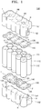
- FIG. 1 is an exploded perspective view illustrating a battery pack 100 according to an embodiment of the present disclosure
- FIG. 2 is an assembled perspective view illustrating elements of the battery pack 100 shown in FIG. 1
- FIG. 3 is an enlarged perspective view illustrating a region A in FIG. 2
- FIG. 4 is a partial perspective view illustrating a positive electrode and a negative electrode of battery cells 110 shown in FIG. 1
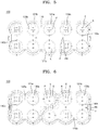
- FIG. 5 is a top view illustrating the battery pack 100 shown in FIG. 2
- FIG. 6 is a bottom view illustrating the battery pack 100 shown in FIG. 2 .
- the battery pack 100 may include the battery cells 110, conductive plates 120, electrode tabs 130, and connection tabs 140.
- each of the battery cells 110 may include: cap plates 111 that are provided on both end portions thereof and respectively have a positive polarity P and a negative polarity N; and an insulation housing 112 that is coupled to the cap plates 111 and surrounds the cap plates 111, wherein the insulation housing 112 seals the inside of the battery cell 110 and includes an insulating material that does not conduct electricity.
- each of the battery cells 110 may include an electrode assembly (not shown) in which a positive electrode plate (not shown) and a negative electrode plate (not shown) are arranged on both sides of a separator (not shown), and the electrode assembly may be rolled up, for example, in a cylindrical shape and may be placed in the insulation housing 112.
- the positive electrode plate may be aluminum foil coated with a positive electrode active material such as lithium cobalt LiCoO 2
- the negative electrode plate may be copper foil coated with a negative electrode active material such as graphite.
- the separator may be provided between the negative electrode plate and the positive electrode plate to prevent an electrical short circuit therebetween and allow movement of lithium ions therebetween.
- the insulation housing 112 may have a cylindrical shape of which both sides (for example, an upper side and a lower side on which the cap plates 111 are provided) are open. That is, the cap plates 111 respectively having a positive polarity P and a negative polarity N may be coupled to both sides of the insulation housing 112.
- the cap plates 111 may include a conductive material such as steel, stainless steel, aluminum, or an equivalent thereof, but embodiments of the present disclosure are not limited thereto.
- one of the positive electrode plate and the negative electrode plate of the electrode assembly may be coupled to the cap plate 111 provided on the upper side to impart a positive polarity P to the cap plate 111 provided on the upper side, and the other may be coupled to the cap plate 111 provided on the lower side to impart a negative polarity N to the cap plate 111 provided on the lower side.
- cap plates 111 having a positive polarity P and cap plates 111 having a negative polarity N may be arranged on the same side.
- cap plates 111 having a positive polarity P and cap plates 111 having a negative polarity N may be arranged on a side of the battery cells 110.
- the battery pack 100 may have any other number of battery cells 110 instead of having ten battery cells 110 shown in the drawings.
- the number of battery cells 110 shown in the drawings, and the number and ratio of cap plates 111 having different polarities and arranged on a side of the battery pack 100 may be variously determined according to design conditions for the battery pack 100. However, for ease of description, the following description will be given based on the case in which five cap plates 111 having a positive polarity P and five cap plates 111 have a negative polarity N are arranged on a side of the battery cells 110.
- the conductive plates 120 may electrically connect the battery cells 110.
- a conductive plate 120 is arranged on an upper side of the battery cells 110, and another conductive plate 120 is arranged on a lower side of the battery cells 110, but embodiments of the present disclosure are not limited thereto.
- a conductive plate 120 may be arranged on one of the upper and lower sides of the battery cells 110.
- positive and negative polarities P and N of the battery cells 110 are arranged on the same side.
- a positive polarity P may be on a center portion of an upper side of a battery cell 110
- a negative polarity N may be on a peripheral portion of the upper side of the battery cell 110.
- the conductive plate 120 may include a first conductive plate (not shown) connected to the positive polarity P of the battery cells 110 and a second conductive plate (not shown) connected to the negative polarity N of the battery cells 110.
- the positive and negative polarities P and N of the battery cells 110 are respectively arranged on both sides of the battery cells 110 with a conductive plate 120 provided on the upper side of the battery cells 110 and a conductive plate 120 provided on the lower side of the battery cells 110.
- the conductive plate 120 on the lower side of the battery cells 110 may include conductive plates 120a and 120b separated from each other.
- the conductive plates 120 may include openings 121 through which the positive polarity P or the negative polarity N of the battery cells 110 is exposed, and the electrode tabs 130 (described later) and the connection tabs 140 (described later) may be arranged in the openings 121.
- the openings 121 may include openings 121a through which the positive polarity P is exposed and openings 121b through which the negative polarity N is exposed.
- the electrode tabs 130 may be electrically connected to the battery cells 110.
- the electrode tabs 130 may be arranged in the openings 121 of the conductive plates 120 as described above and may be electrically connected to the positive polarity P or the negative polarity N of the battery cells 110.
- the electrode tabs 130 may include: positive electrode tabs 130a electrically connected to the cap plates 111 of the battery cells 110 having a positive polarity P; and negative electrode tabs 130b electrically connected to the cap plates 111 of the battery cells 110 having a negative polarity N.
- the electrode tabs 130 having the above-described structure may be electrically connected to the conductive plates 120 through the connection tabs 140 (described later), and owing to this electrical connection between the electrode tabs 130 and the battery cells 110, the battery cells 110 may be connected in series and/or parallel.
- the electrode tabs 130 may further include embossings E and slits S.
- the embossings E and the slits S are elements for facilitating the process of joining the electrode tabs 130 to the battery cells 110 and will be described below in detail with reference to FIGS. 7 to 9 .
- connection tabs 140 electrically connect the conductive plates 120 to the electrode tabs 130, and when an excessive current flows through the connection tabs 140, the connection tabs 140 may melt such that electrical connection between the conductive plates 120 and the electrode tabs 130 may be broken.
- the connection tabs 140 may be thin nickel tabs as shown in FIG. 3 .
- the connection tabs 140 may include connection tabs 140a connected to the positive polarity P and connection tabs 140b connected to the negative polarity N.
- each of the connection tabs 140 may include at least one bent portion 141.
- connection tabs 140 are elements that electrically connect the conductive plates 120 to the electrode tabs 130 and may function as electrical paths for current flowing from the battery cells 110 to the conductive plates 120 or for current flowing from the conductive plates 120 to the battery cells 110 through the electrode tabs 130.
- the reason for this is the structure of the bent portions 141, that is, electrical resistance increases as the length of the connection tabs 140 increases such that when an excessive current flows through the connection tabs 140, the bent portions 141 may melt quickly.
- the battery pack 100 may further include a case 150 that surrounds lateral surfaces of the battery cells 110 and the conductive plates 120 and fixes the battery cells 110 and the conductive plates 120 to each other.
- the case 150 may include a first sub-case 151 covering portions of the battery cells 110 and a second sub-case 152 covering the other portions of the battery cells 110.
- the first sub-case 151 and the second sub-case 152 may include protrusions PR configured to be inserted into fixing holes F of the conductive plates 120 for fixing the conductive plates 120 to the first sub-case 151 and the second sub-case 152.
- one of the first sub-case 151 and the second sub-case 152 may include connection grooves 153 extending toward the other of the first sub-case 151 and the second sub-case 152, and the other of the first sub-case 151 and the second sub-case 152 may include connection projections 154 configured to be inserted into the connection grooves 153 to join the first sub-case 151 and the second sub-case 152 to each other.
- connection grooves 153 may be formed in the first sub-case 151 and may extend in a direction toward the second sub-case 152
- connection projections 154 may be formed on the second sub-case 152 and may extend in a direction toward the first sub-case 151.
- the first sub-case 151 and the second sub-case 152 may be coupled to each other by inserting the connection projections 154 into the connection grooves 153, and thus the battery cells 110 and the conductive plates 120 may be fixed by the first sub-case 151 and the second sub-case 152.
- unexplained reference number H indicates insertion portion of the first sub-case 151 and the second sub-case 152 through which the battery cells 110 are inserted.
- unexplained reference number 122 indicates power input/output of the conductive plate 120.
- FIG. 7 is a cross-sectional view of the battery pack 100, which is taken along line I-I in FIG. 2
- FIG. 8 is a cross-sectional view illustrating another example of the connection tab 140 shown in FIG. 7
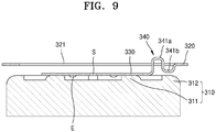
- FIG. 9 is a cross-sectional view illustrating another example of the connection tab 140 shown in FIG. 7 .
- the conductive plate 120 may be spaced apart from each of the battery cells 110 by a given distance.
- the electrode tab 130 may be connected to the cap plate 111 of the battery cell 110, and the connection tab 140 may electrically connect the conductive plate 120 and the electrode tab 130 to each other and may include the bent portion 141.
- the embossings E of the electrode tab 130 are a kind of protrusion protruding toward the battery cell 110 and facilitating coupling between the electrode tab 130 and the battery cell 110.
- the electrode tab 130 is brought into tight contact with the cap plate 111 of the battery cell 110 and is pressed, and at the same time a current is applied through the electrode tab 130 and the cap plate 111, the current concentrates in the embossings E. Accordingly, heat is generated in the embossings E, and thus the embossings E are melted by the heat, thereby joining the cap plate 111 and the electrode tab 130 to each other.
- the slit S of the electrode tab 130 is an element for preventing heat deterioration of the electrode tab 130 that may occur around the embossings E when the battery cell 110 and the electrode tab 130 are joined to each other using the embossings E.
- a shun current that does not actually contribute to welding may flow and may cause heat deterioration between the battery cell 110 and the electrode tab 130.
- the slit S is a structure for minimizing such heat deterioration.
- a conductive plate 220 is located in an imaginary plane in which an electrode tab 230 is positioned, and this means that a portion of the conductive plate 220 is in contact with an insulation housing 212 of a battery cell 210. Even in this structure, a connection tab 240 may include a bent portion 241.
- a conductive plate 320 may be spaced apart from each of a plurality of battery cells 310 by a given distance.
- an electrode tab 330 may be connected to a cap plate 311 of the battery cell 310, and a connection tab 340 may electrically connect the conductive plate 320 and the electrode tab 330 to each other and may include a first sub-bent portion 341a and a second sub-bent portion 341b.
- unexplained reference numbers 211 and 311 indicate cap plate and unexplained reference numbers 312 indicates insulation housing.
- unexplained reference numbers 221 and 321 indicate opening.
- connection tabs 140, 240, or 340 of the embodiments of the present disclosure when a temporarily excessive current flows between the battery cells 110, the bent portions 141 of the connection tabs 140 are melted, and thus the electrical connection between the conductive plates 120 and the electrode tabs 130 may be broken.
- the bent portions 141 may also have a function of lower impact when the battery pack 100 vibrates minutely.
- a temporarily excessive current flowing between the battery cells may be blocked.
Landscapes
- Chemical & Material Sciences (AREA)
- Chemical Kinetics & Catalysis (AREA)
- Electrochemistry (AREA)
- General Chemical & Material Sciences (AREA)
- Connection Of Batteries Or Terminals (AREA)
Abstract
Description
- Embodiments of the present disclosure relate to a battery pack.
- In general, battery cells are used as energy sources in mobile devices, electric vehicles, hybrid vehicles, or other electric devices, and such battery cells may be modified according to the types of devices to which the battery cells are applied.
- For example, small mobile devices such as cellular phones may be operated for a certain period of time by using the power and capacity of only one battery cell. However, high-capacity battery modules each formed by electrically connecting a plurality of battery cells to increase power and capacity may be used in devices such as electric vehicles or hybrid vehicles which consume large amounts of power, have long operating times, and require high-power driving. That is, the output voltage or current of such a battery module may be adjusted by varying the number of battery cells included in the battery module. Such battery modules may be electrically connected to each other to form a battery pack.
- The above-described background art is technical information that the inventor had or learned when or while deriving embodiments of the present disclosure and may not have been publicly known before the filing of the present application.
- Embodiments of the present disclosure may provide a battery pack capable of blocking a temporarily excessive current flowing between a plurality of battery cells.
- An embodiment of the present disclosure provides a battery pack including: a plurality of battery cells; a conductive plate electrically connecting the plurality of battery cells to each other; electrode tabs electrically connected to the plurality of battery cells; and connection tabs electrically connecting the conductive plate to the electrode tabs, the connection tabs being configured such that when an excessive current flows, the connection tabs melt and block the excessive current flowing between the conductive plate and the electrode tabs, wherein each of the connection tabs includes at least one bent portion.
- According to embodiments of the present disclosure, the battery pack is capable of blocking a temporarily excessive current flowing between the plurality of battery cells. However, the scope of the present disclosure is not limited to the effect.
-
-
FIG. 1 is an exploded perspective view illustrating a battery pack according to an embodiment of the present disclosure. -
FIG. 2 is an assembled perspective view illustrating elements of the battery pack shown inFIG. 1 . -
FIG. 3 is an enlarged perspective view illustrating a region A inFIG. 2 . -
FIG. 4 is a partial perspective view illustrating a positive electrode and a negative electrode of battery cells shown inFIG. 1 . -
FIG. 5 is a top view illustrating the battery pack shown inFIG. 2 . -
FIG. 6 is a bottom view illustrating the battery pack shown inFIG. 2 .. -
FIG. 7 is a cross-sectional view of the battery pack, which is taken along line I-I inFIG. 2 . -
FIG. 8 is a cross-sectional view illustrating another example of a connection tab shown inFIG. 7 . -
FIG. 9 is a cross-sectional view illustrating another example of the connection tab shown inFIG. 7 . - An embodiment of the present disclosure provides a battery pack including: a plurality of battery cells; a conductive plate electrically connecting the plurality of battery cells to each other; electrode tabs electrically connected to the plurality of battery cells; and connection tabs electrically connecting the conductive plate to the electrode tabs, the connection tabs being configured such that when an excessive current flows, the connection tabs melt and block the excessive current flowing between the conductive plate and the electrode tabs, wherein each of the connection tabs includes at least one bent portion.
- In the embodiment, the conductive plate may include openings through which positive electrodes or negative electrodes of the plurality of battery cells are exposed, and the electrode tabs and the connection tabs may be arranged in the openings.
- In the embodiment, the conductive plate may be spaced apart from the plurality of battery cells by a given distance.
- In the embodiment, each of the battery cells may include: cap plates provided on both end portions of the battery cell and respectively having a positive polarity and a negative polarity; and an insulation housing coupled to the cap plates while surrounding the cap plates to seal an inside of the battery cell, the insulation housing including an insulating material that does not conduct electricity.
- In the embodiment, the conductive plate may be in an imaginary plane in which the electrode tabs are positioned, and the conductive plate may be in contact with the insulation housing.
- In the embodiments, the electrode tabs may include: positive electrode tabs electrically connected to the cap plates having the positive polarity; and negative electrode tabs electrically connected to the cap plates having the negative polarity.
- In the embodiment, the battery pack may further include a case that surrounds lateral surfaces of the plurality of battery cells and the conductive plate and fixes the plurality of battery cells and the conductive plate.
- In the embodiment, the case may include: a first sub-case covering portions of the plurality of battery cells; and a second sub-case covering other portions of the plurality of battery cells.
- In the embodiment, one of the first sub-case and the second sub-case may include a connection groove extending toward the other of the first sub-case and the second sub-case, and the other of the first sub-case and the second sub-case may include a connection projection inserted in the connection groove for joining the first sub-case and the second sub-case to each other.
- Other aspects, characteristics, and advantages will become apparent and more readily appreciated from the accompanying drawings, claims, and detailed description.
- The present disclosure may be variously modified, and various embodiments may be provided according to the present disclosure. Hereinafter, some embodiments will be illustrated in the accompanying drawings and described in detail. Effects and features of the present disclosure, and implementation methods thereof will be clarified through the following embodiments described in detail with reference to the accompanying drawings. However, the scope and idea of the present disclosure are not limited to the following embodiments but may be implemented in various forms.
- In the following embodiments, it will be understood that although terms such as "first" and "second," are used to describe various elements, these elements should not be limited by these terms. These terms are only used to distinguish one element from another. The terms of a singular form may include plural forms unless referred to the contrary. In addition, terms such as "include" or "comprise" specify features or the presence of stated elements, but do not exclude other features or elements.
- In the drawings, the sizes of elements may be exaggerated for clarity. For example, in the drawings, the size or thickness of each element may be arbitrarily shown for illustrative purposes, and thus the present disclosure should not be construed as being limited thereto.
- In addition, the order of processes explained in one embodiment may be changed in a modification of the embodiment or another embodiment. For example, two consecutively described processes may be performed substantially at the same time or performed in an order opposite to the described order.
- Hereinafter, embodiments of the present disclosure will be described in detail with reference to the accompanying drawings. In the following description given with reference to the accompanying drawings, the same elements or corresponding elements are denoted with the same reference numerals, and overlapping descriptions thereof will be omitted.
-
FIG. 1 is an exploded perspective view illustrating abattery pack 100 according to an embodiment of the present disclosure;FIG. 2 is an assembled perspective view illustrating elements of thebattery pack 100 shown inFIG. 1 ;FIG. 3 is an enlarged perspective view illustrating a region A inFIG. 2 ;FIG. 4 is a partial perspective view illustrating a positive electrode and a negative electrode ofbattery cells 110 shown inFIG. 1 ;FIG. 5 is a top view illustrating thebattery pack 100 shown inFIG. 2 ;FIG. 6 is a bottom view illustrating thebattery pack 100 shown inFIG. 2 . - Referring to
FIG. 1 , thebattery pack 100 according to the embodiment of the present disclosure may include thebattery cells 110,conductive plates 120,electrode tabs 130, andconnection tabs 140. - Referring to
FIGS. 1 and4 , each of thebattery cells 110 may include:cap plates 111 that are provided on both end portions thereof and respectively have a positive polarity P and a negative polarity N; and aninsulation housing 112 that is coupled to thecap plates 111 and surrounds thecap plates 111, wherein the insulation housing 112 seals the inside of thebattery cell 110 and includes an insulating material that does not conduct electricity. - Although not shown in the drawings, each of the
battery cells 110 may include an electrode assembly (not shown) in which a positive electrode plate (not shown) and a negative electrode plate (not shown) are arranged on both sides of a separator (not shown), and the electrode assembly may be rolled up, for example, in a cylindrical shape and may be placed in theinsulation housing 112. - For example, the positive electrode plate may be aluminum foil coated with a positive electrode active material such as lithium cobalt LiCoO2, and the negative electrode plate may be copper foil coated with a negative electrode active material such as graphite. Here, the separator may be provided between the negative electrode plate and the positive electrode plate to prevent an electrical short circuit therebetween and allow movement of lithium ions therebetween.
- The
insulation housing 112 may have a cylindrical shape of which both sides (for example, an upper side and a lower side on which thecap plates 111 are provided) are open. That is, thecap plates 111 respectively having a positive polarity P and a negative polarity N may be coupled to both sides of theinsulation housing 112. Here, thecap plates 111 may include a conductive material such as steel, stainless steel, aluminum, or an equivalent thereof, but embodiments of the present disclosure are not limited thereto. - In detail, one of the positive electrode plate and the negative electrode plate of the electrode assembly may be coupled to the
cap plate 111 provided on the upper side to impart a positive polarity P to thecap plate 111 provided on the upper side, and the other may be coupled to thecap plate 111 provided on the lower side to impart a negative polarity N to thecap plate 111 provided on the lower side. - As shown in the drawings,
cap plates 111 having a positive polarity P andcap plates 111 having a negative polarity N may be arranged on the same side. For example, referring toFIGS. 5 and 6 , fivecap plates 111 having a positive polarity P and fivecap plates 111 having a negative polarity N may be arranged on a side of thebattery cells 110. However, this is an example for illustration, and thebattery pack 100 may have any other number ofbattery cells 110 instead of having tenbattery cells 110 shown in the drawings. - That is, the number of
battery cells 110 shown in the drawings, and the number and ratio ofcap plates 111 having different polarities and arranged on a side of thebattery pack 100 may be variously determined according to design conditions for thebattery pack 100. However, for ease of description, the following description will be given based on the case in which fivecap plates 111 having a positive polarity P and fivecap plates 111 have a negative polarity N are arranged on a side of thebattery cells 110. - Next, the
conductive plates 120 may electrically connect thebattery cells 110. Referring toFIG. 1 , aconductive plate 120 is arranged on an upper side of thebattery cells 110, and anotherconductive plate 120 is arranged on a lower side of thebattery cells 110, but embodiments of the present disclosure are not limited thereto. - For example, although not shown in the drawings, a
conductive plate 120 may be arranged on one of the upper and lower sides of thebattery cells 110. In this case, positive and negative polarities P and N of thebattery cells 110 are arranged on the same side. For example, a positive polarity P may be on a center portion of an upper side of abattery cell 110, and a negative polarity N may be on a peripheral portion of the upper side of thebattery cell 110. - In detail, when positive and negative polarities P and N of the
battery cells 110 are arranged on the same side, theconductive plate 120 may include a first conductive plate (not shown) connected to the positive polarity P of thebattery cells 110 and a second conductive plate (not shown) connected to the negative polarity N of thebattery cells 110. However, for ease of description, the following description will be given based on the case in which the positive and negative polarities P and N of thebattery cells 110 are respectively arranged on both sides of thebattery cells 110 with aconductive plate 120 provided on the upper side of thebattery cells 110 and aconductive plate 120 provided on the lower side of thebattery cells 110. Meanwhile, theconductive plate 120 on the lower side of thebattery cells 110 may includeconductive plates - In detail, the
conductive plates 120 may includeopenings 121 through which the positive polarity P or the negative polarity N of thebattery cells 110 is exposed, and the electrode tabs 130 (described later) and the connection tabs 140 (described later) may be arranged in theopenings 121. Theopenings 121 may includeopenings 121a through which the positive polarity P is exposed andopenings 121b through which the negative polarity N is exposed. - The
electrode tabs 130 may be electrically connected to thebattery cells 110. In detail, theelectrode tabs 130 may be arranged in theopenings 121 of theconductive plates 120 as described above and may be electrically connected to the positive polarity P or the negative polarity N of thebattery cells 110. Here, referring toFIGS. 5 and 6 , theelectrode tabs 130 may include:positive electrode tabs 130a electrically connected to thecap plates 111 of thebattery cells 110 having a positive polarity P; andnegative electrode tabs 130b electrically connected to thecap plates 111 of thebattery cells 110 having a negative polarity N. - The
electrode tabs 130 having the above-described structure may be electrically connected to theconductive plates 120 through the connection tabs 140 (described later), and owing to this electrical connection between theelectrode tabs 130 and thebattery cells 110, thebattery cells 110 may be connected in series and/or parallel. - In addition, the
electrode tabs 130 may further include embossings E and slits S. The embossings E and the slits S are elements for facilitating the process of joining theelectrode tabs 130 to thebattery cells 110 and will be described below in detail with reference toFIGS. 7 to 9 . - The
connection tabs 140 electrically connect theconductive plates 120 to theelectrode tabs 130, and when an excessive current flows through theconnection tabs 140, theconnection tabs 140 may melt such that electrical connection between theconductive plates 120 and theelectrode tabs 130 may be broken. For example, theconnection tabs 140 may be thin nickel tabs as shown inFIG. 3 . Referring toFIGs 5 and 6 , theconnection tabs 140 may includeconnection tabs 140a connected to the positive polarity P andconnection tabs 140b connected to the negative polarity N. Here, each of theconnection tabs 140 may include at least onebent portion 141. - As described above, in a normal state, the
connection tabs 140 are elements that electrically connect theconductive plates 120 to theelectrode tabs 130 and may function as electrical paths for current flowing from thebattery cells 110 to theconductive plates 120 or for current flowing from theconductive plates 120 to thebattery cells 110 through theelectrode tabs 130. - Furthermore, in case of an event such as a temporarily excessive current equal to or greater than 1,500 A, heat is generated in the
bent portions 141, and thebent portions 141 melt and break because of the heat, thereby blocking the current flowing between theconductive plates 120 and theelectrode tabs 130. - The reason for this is the structure of the
bent portions 141, that is, electrical resistance increases as the length of theconnection tabs 140 increases such that when an excessive current flows through theconnection tabs 140, thebent portions 141 may melt quickly. - In addition, the
battery pack 100 may further include acase 150 that surrounds lateral surfaces of thebattery cells 110 and theconductive plates 120 and fixes thebattery cells 110 and theconductive plates 120 to each other. - In detail, the
case 150 may include a first sub-case 151 covering portions of thebattery cells 110 and a second sub-case 152 covering the other portions of thebattery cells 110. In addition, thefirst sub-case 151 and thesecond sub-case 152 may include protrusions PR configured to be inserted into fixing holes F of theconductive plates 120 for fixing theconductive plates 120 to thefirst sub-case 151 and thesecond sub-case 152. - In addition, one of the
first sub-case 151 and thesecond sub-case 152 may includeconnection grooves 153 extending toward the other of thefirst sub-case 151 and thesecond sub-case 152, and the other of thefirst sub-case 151 and thesecond sub-case 152 may includeconnection projections 154 configured to be inserted into theconnection grooves 153 to join thefirst sub-case 151 and the second sub-case 152 to each other. - For example, referring to
FIGS. 1 and2 , theconnection grooves 153 may be formed in thefirst sub-case 151 and may extend in a direction toward thesecond sub-case 152, and theconnection projections 154 may be formed on thesecond sub-case 152 and may extend in a direction toward thefirst sub-case 151. According to this structure, thefirst sub-case 151 and thesecond sub-case 152 may be coupled to each other by inserting theconnection projections 154 into theconnection grooves 153, and thus thebattery cells 110 and theconductive plates 120 may be fixed by thefirst sub-case 151 and thesecond sub-case 152. Meanwhile, in theFIG. 1 , unexplained reference number H indicates insertion portion of thefirst sub-case 151 and the second sub-case 152 through which thebattery cells 110 are inserted. Also, in theFIG. 1 ,unexplained reference number 122 indicates power input/output of theconductive plate 120. - Hereinafter, structural characteristics of the
battery cells 110, theconductive plates 120, theelectrode tabs 130, and theconnection tabs 140 will be described in more detail with reference toFIGS. 7 to 9 . -
FIG. 7 is a cross-sectional view of thebattery pack 100, which is taken along line I-I inFIG. 2 ,FIG. 8 is a cross-sectional view illustrating another example of theconnection tab 140 shown inFIG. 7 , andFIG. 9 is a cross-sectional view illustrating another example of theconnection tab 140 shown inFIG. 7 . - First, referring to
FIG. 7 , theconductive plate 120 may be spaced apart from each of thebattery cells 110 by a given distance. In addition, theelectrode tab 130 may be connected to thecap plate 111 of thebattery cell 110, and theconnection tab 140 may electrically connect theconductive plate 120 and theelectrode tab 130 to each other and may include thebent portion 141. - In addition, the embossings E of the
electrode tab 130 are a kind of protrusion protruding toward thebattery cell 110 and facilitating coupling between theelectrode tab 130 and thebattery cell 110. Specifically, when theelectrode tab 130 is brought into tight contact with thecap plate 111 of thebattery cell 110 and is pressed, and at the same time a current is applied through theelectrode tab 130 and thecap plate 111, the current concentrates in the embossings E. Accordingly, heat is generated in the embossings E, and thus the embossings E are melted by the heat, thereby joining thecap plate 111 and theelectrode tab 130 to each other. - In addition, the slit S of the
electrode tab 130 is an element for preventing heat deterioration of theelectrode tab 130 that may occur around the embossings E when thebattery cell 110 and theelectrode tab 130 are joined to each other using the embossings E. Specifically, when a current is applied to join theelectrode tab 130 to thebattery cell 110, a shun current that does not actually contribute to welding may flow and may cause heat deterioration between thebattery cell 110 and theelectrode tab 130. The slit S is a structure for minimizing such heat deterioration. - Next, referring to
FIG. 8 , aconductive plate 220 is located in an imaginary plane in which anelectrode tab 230 is positioned, and this means that a portion of theconductive plate 220 is in contact with aninsulation housing 212 of abattery cell 210. Even in this structure, aconnection tab 240 may include abent portion 241. - Next, referring to
FIG. 9 , aconductive plate 320 may be spaced apart from each of a plurality ofbattery cells 310 by a given distance. In addition, anelectrode tab 330 may be connected to acap plate 311 of thebattery cell 310, and aconnection tab 340 may electrically connect theconductive plate 320 and theelectrode tab 330 to each other and may include a firstsub-bent portion 341a and a secondsub-bent portion 341b. Meanwhile, in theFIGs 8 and9 ,unexplained reference numbers unexplained reference numbers 312 indicates insulation housing. Also, in theFIGs 8 and9 ,unexplained reference numbers - According to the
battery pack 100 including theconnection tabs battery cells 110, thebent portions 141 of theconnection tabs 140 are melted, and thus the electrical connection between theconductive plates 120 and theelectrode tabs 130 may be broken. In addition, thebent portions 141 may also have a function of lower impact when thebattery pack 100 vibrates minutely. - While embodiments of the present disclosure have been described with reference to the accompanying drawings, these embodiments are for illustrative purposes only, and it will be understood by those of ordinary skill in the art that various changes and modifications may be made therefrom. Therefore, the scope and spirit of the present disclosure should be defined by the following claims.
- According to the battery pack of the embodiments of the present disclosure, a temporarily excessive current flowing between the battery cells may be blocked..
Claims (9)
- A battery pack comprising:a plurality of battery cells;a conductive plate electrically connecting the plurality of battery cells to each other;electrode tabs electrically connected to the plurality of battery cells; andconnection tabs electrically connecting the conductive plate to the electrode tabs, the connection tabs being configured such that, when an excessive current flows, the connection tabs melt and block the excessive current flowing between the conductive plate and the electrode tabs,wherein each of the connection tabs comprises at least one bent portion.
- The battery pack of claim 1, wherein the conductive plate comprises openings through which positive electrodes or negative electrodes of the plurality of battery cells are exposed, and
the electrode tabs and the connection tabs are arranged in the openings. - The battery pack of claim 1, wherein the conductive plate is spaced apart from the plurality of battery cells by a given distance.
- The battery pack of claim 1, wherein each of the battery cells comprises:cap plates provided on both end portions of the battery cell and respectively having a positive polarity and a negative polarity; andan insulation housing coupled to the cap plates while surrounding the cap plates to seal an inside of the battery cell, the insulation housing comprising an insulating material that does not conduct electricity.
- The battery pack of claim 4, wherein the conductive plate is in an imaginary plane in which the electrode tabs are positioned, and the conductive plate is in contact with the insulation housing.
- The battery pack of claim 4, wherein the electrode tabs comprise:positive electrode tabs electrically connected to the cap plates having the positive polarity; andnegative electrode tabs electrically connected to the cap plates having the negative polarity.
- The battery pack of claim 1, further comprising a case that surrounds lateral surfaces of the plurality of battery cells and the conductive plate and fixes the plurality of battery cells and the conductive plate.
- The battery pack of claim 7, wherein the case comprises:a first sub-case covering portions of the plurality of battery cells; anda second sub-case covering other portions of the plurality of battery cells.
- The battery pack of claim 8, wherein one of the first sub-case and the second sub-case comprises a connection groove extending toward the other of the first sub-case and the second sub-case, and
the other of the first sub-case and the second sub-case comprises a connection projection inserted in the connection groove for joining the first sub-case and the second sub-case to each other.
Applications Claiming Priority (2)
| Application Number | Priority Date | Filing Date | Title |
|---|---|---|---|
| KR1020170068658A KR102332338B1 (en) | 2017-06-01 | 2017-06-01 | Battery pack |
| PCT/KR2018/001228 WO2018221828A1 (en) | 2017-06-01 | 2018-01-29 | Battery pack |
Publications (2)
| Publication Number | Publication Date |
|---|---|
| EP3633762A1 true EP3633762A1 (en) | 2020-04-08 |
| EP3633762A4 EP3633762A4 (en) | 2021-03-10 |
Family
ID=64456090
Family Applications (1)
| Application Number | Title | Priority Date | Filing Date |
|---|---|---|---|
| EP18809960.0A Pending EP3633762A4 (en) | 2017-06-01 | 2018-01-29 | BATTERY PACK |
Country Status (5)
| Country | Link |
|---|---|
| US (1) | US20200168878A1 (en) |
| EP (1) | EP3633762A4 (en) |
| KR (1) | KR102332338B1 (en) |
| CN (1) | CN110710017B (en) |
| WO (1) | WO2018221828A1 (en) |
Cited By (2)
| Publication number | Priority date | Publication date | Assignee | Title |
|---|---|---|---|---|
| WO2021210021A1 (en) * | 2020-04-16 | 2021-10-21 | Tvs Motor Company Limited | Interconnecting structure for energy storage cells |
| EP4346002A4 (en) * | 2021-09-03 | 2025-02-26 | LG Energy Solution, Ltd. | CYLINDRICAL SECONDARY BATTERY MODULE, AND SECONDARY BATTERY PACK AND VEHICLE COMPRISING SAME |
Families Citing this family (7)
| Publication number | Priority date | Publication date | Assignee | Title |
|---|---|---|---|---|
| KR102350459B1 (en) * | 2017-12-07 | 2022-01-11 | 주식회사 엘지에너지솔루션 | Cylindrical secondary battery module |
| CN112582759B (en) * | 2019-09-30 | 2022-05-13 | 比亚迪股份有限公司 | Battery module and electric automobile |
| KR102598325B1 (en) * | 2021-07-13 | 2023-11-02 | (주)코미트 | Series-parallel lithium-ion battery packs with a surface-mounted electrode bonding plate with circular nickel terminals |
| CN113921890A (en) * | 2021-10-08 | 2022-01-11 | 陕西奥林波斯电力能源有限责任公司 | Large-capacity battery with shunting structure |
| CN217641696U (en) * | 2021-11-01 | 2022-10-21 | 宁德时代新能源科技股份有限公司 | A battery sampling assembly, a battery cell fixing bracket, a battery module and an electrical device |
| CN217387271U (en) * | 2021-12-27 | 2022-09-06 | 比亚迪股份有限公司 | Voltage acquisition structure and battery module with same |
| IT202300015369A1 (en) * | 2023-07-21 | 2025-01-21 | Stellantis Europe Spa | BATTERY MODULE COMPRISING BATTERY CELLS WITHOUT THE METAL COVERING SHELL |
Family Cites Families (21)
| Publication number | Priority date | Publication date | Assignee | Title |
|---|---|---|---|---|
| JP3807186B2 (en) * | 2000-02-29 | 2006-08-09 | 松下電工株式会社 | Battery pack |
| JP4632754B2 (en) * | 2004-11-09 | 2011-02-16 | 三洋電機株式会社 | Pack battery |
| KR100886571B1 (en) * | 2006-08-07 | 2009-03-05 | 주식회사 엘지화학 | Battery pack case |
| JP5372562B2 (en) * | 2009-03-21 | 2013-12-18 | 三洋電機株式会社 | Battery pack |
| JP2010282811A (en) * | 2009-06-04 | 2010-12-16 | Sanyo Electric Co Ltd | Pack battery |
| JP4815016B2 (en) * | 2009-07-17 | 2011-11-16 | パナソニック株式会社 | Battery connecting member and battery module using the same |
| US20110250488A1 (en) * | 2010-04-12 | 2011-10-13 | Sin-Young Park | Secondary battery |
| EP2579360A1 (en) * | 2010-06-02 | 2013-04-10 | Panasonic Corporation | Battery module |
| CN102947973A (en) * | 2010-06-14 | 2013-02-27 | 松下电器产业株式会社 | Battery assembly production method and battery assembly |
| US8486283B2 (en) * | 2010-11-02 | 2013-07-16 | Sinoelectric Powertrain Corporation | Method of making fusible links |
| JP5704645B2 (en) * | 2011-03-30 | 2015-04-22 | Necエナジーデバイス株式会社 | Secondary battery |
| JP6049251B2 (en) * | 2011-11-25 | 2016-12-21 | 三洋電機株式会社 | Battery pack |
| JP6018937B2 (en) * | 2013-01-29 | 2016-11-02 | 三洋電機株式会社 | Electrode member and battery block |
| JP6006134B2 (en) * | 2013-02-08 | 2016-10-12 | トヨタ自動車株式会社 | Connecting member |
| JP6400295B2 (en) * | 2014-01-24 | 2018-10-03 | ダイキョーニシカワ株式会社 | Battery module |
| CN106415882A (en) * | 2014-05-08 | 2017-02-15 | 高科技股份公司 | Battery pack and method of assembling the battery pack |
| US10211443B2 (en) * | 2014-09-10 | 2019-02-19 | Cellink Corporation | Battery interconnects |
| WO2016072054A1 (en) * | 2014-11-04 | 2016-05-12 | パナソニックIpマネジメント株式会社 | Electrode member, current collecting plate, and battery block |
| DE102014017622A1 (en) * | 2014-11-27 | 2016-06-02 | Audi Ag | Connecting element, current collecting device and associated manufacturing method |
| CN205488268U (en) * | 2015-12-31 | 2016-08-17 | 深圳市沃特玛电池有限公司 | Power battery module |
| CN206022510U (en) * | 2016-09-05 | 2017-03-15 | 深圳市沃特玛电池有限公司 | Lithium battery and lithium battery module |
-
2017
- 2017-06-01 KR KR1020170068658A patent/KR102332338B1/en active Active
-
2018
- 2018-01-29 CN CN201880035014.3A patent/CN110710017B/en active Active
- 2018-01-29 WO PCT/KR2018/001228 patent/WO2018221828A1/en not_active Ceased
- 2018-01-29 US US16/611,070 patent/US20200168878A1/en not_active Abandoned
- 2018-01-29 EP EP18809960.0A patent/EP3633762A4/en active Pending
Cited By (3)
| Publication number | Priority date | Publication date | Assignee | Title |
|---|---|---|---|---|
| WO2021210021A1 (en) * | 2020-04-16 | 2021-10-21 | Tvs Motor Company Limited | Interconnecting structure for energy storage cells |
| US12609415B2 (en) | 2020-04-16 | 2026-04-21 | Tvs Motor Company Limited | Interconnecting structure for energy storage cells |
| EP4346002A4 (en) * | 2021-09-03 | 2025-02-26 | LG Energy Solution, Ltd. | CYLINDRICAL SECONDARY BATTERY MODULE, AND SECONDARY BATTERY PACK AND VEHICLE COMPRISING SAME |
Also Published As
| Publication number | Publication date |
|---|---|
| KR102332338B1 (en) | 2021-11-29 |
| CN110710017B (en) | 2023-04-04 |
| WO2018221828A1 (en) | 2018-12-06 |
| KR20180131921A (en) | 2018-12-11 |
| US20200168878A1 (en) | 2020-05-28 |
| EP3633762A4 (en) | 2021-03-10 |
| CN110710017A (en) | 2020-01-17 |
Similar Documents
| Publication | Publication Date | Title |
|---|---|---|
| EP3633762A1 (en) | Battery pack | |
| US11824175B2 (en) | Battery module | |
| JP5345648B2 (en) | Secondary battery and battery module | |
| EP2816637B1 (en) | Rechargeable battery | |
| US9225002B2 (en) | Rechargeable battery having fuse unit | |
| US9136524B2 (en) | Secondary battery | |
| US20120121966A1 (en) | Terminal of rechargeable battery, method of assembling the terminal of rechargeable battery, rechargeable battery module and method of assembling the rechargeable battery module | |
| CN109428043B (en) | Secondary battery | |
| KR20150086841A (en) | Battery module having short connecting part | |
| EP3544078B1 (en) | Secondary battery | |
| KR101724006B1 (en) | Rechargeable battery | |
| CN103367688A (en) | Secondary bttery | |
| KR102612060B1 (en) | Rechargeable battery having membrane | |
| KR20160118689A (en) | Hollow-shaped rechargeable battery | |
| KR20150045737A (en) | Battery Module | |
| KR20180014576A (en) | Rechargeable battery | |
| KR20150035205A (en) | Secondary battery | |
| KR20170024842A (en) | Battery module | |
| KR101233535B1 (en) | Secondary battery | |
| KR102306443B1 (en) | Rechargeable batter00y | |
| KR102578859B1 (en) | Rechargeable battery | |
| KR102296817B1 (en) | Rechargeable battery |
Legal Events
| Date | Code | Title | Description |
|---|---|---|---|
| STAA | Information on the status of an ep patent application or granted ep patent |
Free format text: STATUS: THE INTERNATIONAL PUBLICATION HAS BEEN MADE |
|
| PUAI | Public reference made under article 153(3) epc to a published international application that has entered the european phase |
Free format text: ORIGINAL CODE: 0009012 |
|
| STAA | Information on the status of an ep patent application or granted ep patent |
Free format text: STATUS: REQUEST FOR EXAMINATION WAS MADE |
|
| 17P | Request for examination filed |
Effective date: 20191030 |
|
| AK | Designated contracting states |
Kind code of ref document: A1 Designated state(s): AL AT BE BG CH CY CZ DE DK EE ES FI FR GB GR HR HU IE IS IT LI LT LU LV MC MK MT NL NO PL PT RO RS SE SI SK SM TR |
|
| AX | Request for extension of the european patent |
Extension state: BA ME |
|
| DAV | Request for validation of the european patent (deleted) | ||
| DAX | Request for extension of the european patent (deleted) | ||
| REG | Reference to a national code |
Ref country code: DE Ref legal event code: R079 Free format text: PREVIOUS MAIN CLASS: H01M0002100000 Ipc: H01M0050583000 |
|
| A4 | Supplementary search report drawn up and despatched |
Effective date: 20210210 |
|
| RIC1 | Information provided on ipc code assigned before grant |
Ipc: H01M 50/503 20210101ALI20210204BHEP Ipc: H01M 50/583 20210101AFI20210204BHEP Ipc: H01M 50/548 20210101ALI20210204BHEP |
|
| STAA | Information on the status of an ep patent application or granted ep patent |
Free format text: STATUS: EXAMINATION IS IN PROGRESS |
|
| 17Q | First examination report despatched |
Effective date: 20230404 |