EP3633708A1 - Current blocking element and ozone generation device - Google Patents
Current blocking element and ozone generation device Download PDFInfo
- Publication number
- EP3633708A1 EP3633708A1 EP17912067.0A EP17912067A EP3633708A1 EP 3633708 A1 EP3633708 A1 EP 3633708A1 EP 17912067 A EP17912067 A EP 17912067A EP 3633708 A1 EP3633708 A1 EP 3633708A1
- Authority
- EP
- European Patent Office
- Prior art keywords
- electrode
- fixed
- current blocking
- blocking element
- generation device
- Prior art date
- Legal status (The legal status is an assumption and is not a legal conclusion. Google has not performed a legal analysis and makes no representation as to the accuracy of the status listed.)
- Granted
Links
Images




Classifications
-
- H—ELECTRICITY
- H05—ELECTRIC TECHNIQUES NOT OTHERWISE PROVIDED FOR
- H05H—PLASMA TECHNIQUE; PRODUCTION OF ACCELERATED ELECTRICALLY-CHARGED PARTICLES OR OF NEUTRONS; PRODUCTION OR ACCELERATION OF NEUTRAL MOLECULAR OR ATOMIC BEAMS
- H05H1/00—Generating plasma; Handling plasma
- H05H1/24—Generating plasma
- H05H1/2406—Generating plasma using dielectric barrier discharges, i.e. with a dielectric interposed between the electrodes
-
- H—ELECTRICITY
- H01—ELECTRIC ELEMENTS
- H01H—ELECTRIC SWITCHES; RELAYS; SELECTORS; EMERGENCY PROTECTIVE DEVICES
- H01H85/00—Protective devices in which the current flows through a part of fusible material and this current is interrupted by displacement of the fusible material when this current becomes excessive
- H01H85/0013—Means for preventing damage, e.g. by ambient influences to the fuse
- H01H85/0017—Means for preventing damage, e.g. by ambient influences to the fuse due to vibration or other mechanical forces, e.g. centrifugal forces
-
- C—CHEMISTRY; METALLURGY
- C01—INORGANIC CHEMISTRY
- C01B—NON-METALLIC ELEMENTS; COMPOUNDS THEREOF; METALLOIDS OR COMPOUNDS THEREOF NOT COVERED BY SUBCLASS C01C
- C01B13/00—Oxygen; Ozone; Oxides or hydroxides in general
- C01B13/10—Preparation of ozone
- C01B13/11—Preparation of ozone by electric discharge
-
- H—ELECTRICITY
- H01—ELECTRIC ELEMENTS
- H01H—ELECTRIC SWITCHES; RELAYS; SELECTORS; EMERGENCY PROTECTIVE DEVICES
- H01H23/00—Tumbler or rocker switches, i.e. switches characterised by being operated by rocking an operating member in the form of a rocker button
-
- H—ELECTRICITY
- H01—ELECTRIC ELEMENTS
- H01H—ELECTRIC SWITCHES; RELAYS; SELECTORS; EMERGENCY PROTECTIVE DEVICES
- H01H85/00—Protective devices in which the current flows through a part of fusible material and this current is interrupted by displacement of the fusible material when this current becomes excessive
- H01H85/02—Details
- H01H85/04—Fuses, i.e. expendable parts of the protective device, e.g. cartridges
- H01H85/05—Component parts thereof
-
- H—ELECTRICITY
- H01—ELECTRIC ELEMENTS
- H01H—ELECTRIC SWITCHES; RELAYS; SELECTORS; EMERGENCY PROTECTIVE DEVICES
- H01H85/00—Protective devices in which the current flows through a part of fusible material and this current is interrupted by displacement of the fusible material when this current becomes excessive
- H01H85/48—Protective devices wherein the fuse is carried or held directly by the base
-
- H—ELECTRICITY
- H01—ELECTRIC ELEMENTS
- H01H—ELECTRIC SWITCHES; RELAYS; SELECTORS; EMERGENCY PROTECTIVE DEVICES
- H01H85/00—Protective devices in which the current flows through a part of fusible material and this current is interrupted by displacement of the fusible material when this current becomes excessive
- H01H85/0013—Means for preventing damage, e.g. by ambient influences to the fuse
- H01H85/0021—Means for preventing damage, e.g. by ambient influences to the fuse water or dustproof devices
- H01H85/0026—Means for preventing damage, e.g. by ambient influences to the fuse water or dustproof devices casings for the fuse and its base contacts
-
- H—ELECTRICITY
- H01—ELECTRIC ELEMENTS
- H01H—ELECTRIC SWITCHES; RELAYS; SELECTORS; EMERGENCY PROTECTIVE DEVICES
- H01H85/00—Protective devices in which the current flows through a part of fusible material and this current is interrupted by displacement of the fusible material when this current becomes excessive
- H01H85/02—Details
- H01H85/20—Bases for supporting the fuse; Separate parts thereof
-
- H—ELECTRICITY
- H01—ELECTRIC ELEMENTS
- H01T—SPARK GAPS; OVERVOLTAGE ARRESTERS USING SPARK GAPS; SPARKING PLUGS; CORONA DEVICES; GENERATING IONS TO BE INTRODUCED INTO NON-ENCLOSED GASES
- H01T19/00—Devices providing for corona discharge
Definitions
- This invention relates to an ozone generation device which ozonizes an oxygen-containing gas by discharging, especially relates to a current blocking element which is provided for protecting operation.
- FIG.11 is a cross-sectional view showing the general configuration of a fuse which is used for a high voltage.
- a fuse element 30 is inserted and both ends of the fuse element 30 is electrically connected and fixed to caps 14a and 14b which are provided at both ends of the ceramic tube 31.
- caps 14a and 14b which are provided at both ends of the ceramic tube 31.
- silica sand 32 is filled around a fuse element, heat of an arc is absorbed by silica sand, and an arc plasma density is thinned.
- FIG.12 shows an example of a current blocking element which is disclosed by Patent Document 2.
- a fuse conductor generates heat due to a current which flows during normal operation, at both ends of the fuse conductor 36, a fuse connecting plate 35 having enough surface area which can be cooled is connected, generated heat in the fuse conductor 36 is released from the fuse cooling plate 35 to surrounding gas atmosphere, and increase of temperature of the fuse conductor 36 is suppressed.
- a current blocking element which is disclosed by Patent Document 2 is provided inside a dielectric tube (glass tube) being away from a glass tube. Further, when a stainless material is used as a material of a fuse conductor, a current blocking element can be configured to be stable even in high oxidation atmosphere in an ozone generation device.
- a size of a fuse is large.
- a typical voltage which is applied to an ozone generation device is 3 to 7kV, and a current is 0.2 to 1A.
- a voltage is high, therefore it is necessary to apply a fuse for power, regarding a size of a fuse, an outer diameter is 20 to 40mm and a length is 110 to 200mm, that is, there is a problems such that a size of a fuse is large.
- This invention is made so as to solve the above mentioned problems, and aims to provide an ozone generation device having a highly reliable current blocking element in which a thin discharge tube can be used and which can reduce a size of an ozone generation device.
- a current blocking element has a configuration such that at each side of both ends of a fusing element having a configuration such that a fuse conductor which is melted by overcurrent is connected to both sides of an intermediate conductor, individually, a fixed electrode having plate shape is connected, and a plate surface of each fixed electrode is fixed to a surface of a base of a dielectric by a fixing material.
- an ozone generation device comprises a plurality of discharge tubes which is constituted by a dielectric tube having a voltage applying electrode inside the dielectric tube and a ground metal electrode which is arranged so as to have a discharge gap between an inner surface of the ground metal electrode and an outer surface of the dielectric tube, gas containing oxygen is flown in the discharge gap, by applying an AC voltage from an AC power source to between the voltage applying electrode and the ground metal electrode, the gas containing oxygen is discharged to be an ozonized gas.
- a current blocking element which has a configuration such that at each side of both ends of a fusing element having a configuration such that a fuse conductor which is melted by overcurrent is connected to both sides of an intermediate conductor, individually, a fixed electrode having plate shape is connected, and a plate surface of each fixed electrode is fixed to a surface of a base of a dielectric by a fixing material, is connected between an AC power source and each voltage applying electrode of a plurality of discharge tubes, individually.
- This invention can provide an ozone generation device having a current blocking element by which breakdown of a fuse conductor due to mechanical stress can be suppressed, and in which a thin discharge tube can be used.
- FIG.1 is a cross-sectional view showing the schematic configuration of an ozone generation device in Embodiment 1 of this invention.
- a pair of a cylindrical shaped dielectric tube 1 and a ground metal electrode 11 constitute one discharge tube.
- FIG.1 in order to describe the details of a discharge tube, only two discharge tubes are shown, however, in a large-capacity ozone generation device, in one body container of a ozone generation device 12, several hundred discharge tubes are provided.
- the dielectric tube 1 is comprised of a cylindrical shaped glass tube
- the ground metal electrode 11 is comprised of a pipe which is made of stainless, via a spacer which is not shown in FIG., the dielectric tube 1 and the ground metal electrode 11 are disposed concentrically, and between the dielectric tube 1 and the ground metal electrode 11, a narrow discharge gap 25 is formed.
- One end (right end) of the dielectric tube 1 is closed and other end (left end) of the dielectric tube 1 is opened.
- a voltage applying electrode 2 is disposed in the dielectric tube 1.
- the voltage applying electrode 2 is comprised of a metal film which is formed by evaporating in an inner surface of the dielectric tube 1.
- the dielectric tube 1 having the voltage applying electrode 2 which is formed on an inner surface thereof and the ground metal electrode 11 constitute a discharge tube.
- the voltage applying electrode 2 is connected to an output end of an AC voltage generation part 21 in an AC power source 16 via an electrical connecting member 9, a current blocking element 7, a power supplying member 8 and a power supplying lead wire 14.
- Other end of the AC voltage generation part 21 is grounded, and the body container of the ozone generation device 12 is also grounded.
- a part where the power supplying lead wire 14 is penetrated into the body container of the ozone generation device 12 which is ground potential is insulated by a bushing 15.
- An AC voltage which is generated by the AC voltage generation part 21 of the AC power source 16 is a high voltage which is high enough to generate a discharge in the discharge gap 25, and frequency of an AC is frequency which can generate discharge via a dielectric, that is, which can generate silent discharge.
- the AC voltage generation part 21 generates high frequency AC voltage, for example, voltage is 3 to 7kV and frequency is 0.5 to 5 kHz.
- a voltage applying electrode is not necessary for a voltage applying electrode to be a metal film which is formed on an inner surface, and any metal body which is disposed in the dielectric tube 1 is acceptable.
- a configuration in which a voltage is applied between the voltage applying electrode and the ground metal electrode 11 via a dielectric body, in which at any position between a voltage applying electrode and a ground electrode, a discharge gap is formed and in which in the discharge gap, so-called silent discharge is generated is acceptable.
- a power source control part 22 and an output voltage drop detection part 23 are provided in the AC power source 16.
- the output voltage drop detection part 23 is connected between the supplying power lead wire 14 and the ground, and based on a signal of the output voltage drop detection 23, decrease of an output voltage will be detected and the detected signal will be transmitted to the power source control part 22.
- the power source control part 22 performs controlling of operation or stop of a device and performs monitoring control of an AC power source.
- the body container of the ozone generation device 12 and the AC power source 16 constitute an ozone generation device.
- the pipe-shaped ground metal electrode 11 which is made of stainless is connected to end plates 13 which are provided at both ends thereof by welding, etc., and the end plates 13 are connected to the body container of the ozone generation device 12 by welding, etc.
- the body container of the ozone generation device 12 is divided into three rooms by the end plates 13, and the rooms which are positioned at left side and right side are gas space and the room which is positioned at center is filled with cooling water 24. It is configured for the cooling water to flow from an inlet of cooling water 19 to an outlet of cooling water 20.
- Material gas containing oxygen is introduced from an inlet of material gas 17, and while the material gas passed through a discharge gap 25, gas is ozonized by discharging and is exhausted from an outlet of gas containing ozone 18, and is utilized for ozone treatment, etc.
- FIG.2A and FIG.2B are enlarged cross-sectional views showing a configuration of a current blocking element 7,
- FIG.2A is a cross-sectional view in the longitudinal direction of the dielectric tube 1 at a side of a supplying power part and
- FIG.2B is a cross-sectional view in the lateral direction thereof.
- a fuse conductor 5a and a fuse conductor 5c are connected, and the fuse conductor 5a, the intermediate conductor 5b and the fuse conductor 5c constitute a fusing element 5.
- a fixed electrode 3 At a side of the fuse conductor 5a which is opposite to a side where the intermediate conductor 5b is connected, a fixed electrode 3 at a side of supplying power is connected.
- a fixed electrode 4 at a side of voltage applying electrode is connected at a side of the fuse conductor 5c which is opposite to a side where the intermediate conductor 5b is connected.
- the fixed electrode 3 at a side of supplying power and the fixed electrode 4 at a side of voltage applying electrode are plate-shaped. As it will be described later, a thickness of the plate may be that of a thin foil, for example, 0.02mm.
- a surface of the plate of the fixed electrode 3 at a side of supplying power is fixed to an inner surface of the dielectric tube 1 by a fixing material 3a and a surface of the plate of the fixed electrode 4 at a side of supplying power is fixed to an inner surface of the dielectric tube 1 by a fixing material 4a, individually.
- the fixing material 3a and the fixing material 4a are constituted by an adhesive having excellent thermal conductivity, an epoxy-based high thermal conductive adhesive, a conductive adhesive, an inorganic-based adhesive, etc.
- an electrical connecting member 9 is connected, and to the fixed electrode 3 at a side of supplying power, a power supplying member 8 is connected, individually.
- the dielectric tube 1 is provided in a horizontal direction, and as shown in FIG.2B , the current blocking element 7 is provided at an upper side of inside of the dielectric tube 1.
- the current blocking element 7 comprises a fusing element 5 in which the fuse conductor 5a and the fuse conductor 5c are connected to both sides of the intermediate conductor 5b, the plate-shaped fixed electrode 3 which is connected at a side of the fuse conductor 5a which is opposite to a side where the intermediate conductor 5b is connected, and the plate-shaped fixed electrode 4 which is connected at a side of the fuse conductor 5c which is opposite to a side where the intermediate conductor 5b is connected, and a plate surface of each fixed electrode is fixed to an inner surface of the dielectric tube 1 by fixing materials.
- a part of the dielectric tube 1 which constitutes the current blocking element 7 also refers to as a base.
- FIG.2A and FIG.2B a size of a fixed electrode, an intermediate conductor, a fuse conductor and a fixing material shown in FIG.2A and FIG.2B is shown differently from that of actual size ratio against other member of each section, and in order to make the arrangement of each member understandable, in FIG., it is shown such that a size is enlarged, or each member is emphasized.
- a power source control part 22 of an AC power source 16 transmits an operation command to an AC voltage generation part 21
- a high frequency AC voltage which is outputted from the AC voltage generation part 21 is applied to a voltage applying electrode 2 through a power supplying lead wire 14, the power supplying member 8, the current blocking element 7 and the electrical connecting member 9.
- a high frequency AC voltage is applied to narrow discharge gap 25 which is formed between the voltage applying electrode 2 and the ground metal electrode 11, in the discharge gap 25, discharge is generated.
- a size of the discharge gap is set to be less than 0.6 mm.
- a material gas component is dry air or an oxygen gas to which very small amount of nitrogen gas is added. It is necessary for a material gas to contain oxygen at least. A temperature of the voltage applying electrode 2 and the ground metal electrode 11 are increased due to heat which is generated by discharge, therefore cooling water 24 is flown through an inlet of cooling water 19 and an outlet of cooling water 20 to perform cooling.
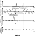
- a command value of the power source control part 22 in an operation state or in a breakdown state, waveforms of voltage and current at each part will be shown in FIG.3 .
- the AC power source 16 becomes an operation state so as to output a high frequency high voltage.
- a load side of the AC power source 16 becomes a short circuit state, therefore, a power source output voltage is dropped to be close to zero and at the same time, a large short circuit current will flow in the dielectric tube 1 which is broken down and the current blocking element 7.
- an output voltage drop detecting part 23 detects an output voltage drop and transmits the result to the power source control part 22.
- the power source control part 22 judges such that a short circuit is generated at a power source output side (short circuit detection) and transmits an operation stop command to the AC voltage generation part 21.
- the AC power source 16 stops an output, a power source output voltage is dropped to be zero, and a large short circuit current which flows in an electrode which is broken down is dropped to be zero.
- An arc discharge which is generated in the fuse conductor 5a and the fuse conductor 5c is extinguished when a large short circuit current is dropped.
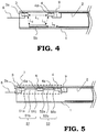
- the fuse conductor 5a and the fuse conductor 5c shown in FIG.2A are extinguished by melting, as a result, the intermediate conductor 5b loses supporting at both ends, and therefore, as shown in FIG.4 , the intermediate conductor 5b is dropped to a bottom of inside of the dielectric tube 1. Between the fixed electrode 3 at a power supplying side and the voltage applying electrode 2, an insulation distance shown in FIG.4 is secured.
- an insulation distance is sufficiently secured, therefore even when high frequency high voltage is applied to the fixed voltage 3 at a power supplying side again, an arc discharge will not be generated in a part where the above mentioned insulation distance is indicated.
- an insulation distance is 14mm or larger, that is the twice of the above mentioned distance.
- an operation voltage of an ozone generation device is low, for example, in a case of 4kV, by making an insulation distance 4mm or larger, a size of a current blocking element can be reduced further.
- a period of time from operation stop command to operation restart command is predetermined.
- the above mentioned period of time may be set as a period of time which is longer than continuing time of an arc discharge which is generated in the fuse conductor 5a and the fuse conductor 5c.
- the above mentioned predetermined period of time is for example, 1 to 10 seconds.
- a method for detecting breakdown of a dielectric tube that is, breakdown of a discharge tube
- a case in which a drop of output voltage is detected by measuring by the output voltage drop detection part 23 which is provided in an AC power source is described, however, when breakdown of discharge tube is detected by using other methods, for example, a method for detecting an increase of output current, a method in which a plurality of discharge tubes are divided into two and output of power sources is divided into two so as to apply a current and detect by difference of current value, and a method in which light which is emitted from an arc discharge in a body container of an ozone generation device is measured, breakdown of a discharge tube is detected so as to control an output of the AC power source 16, same effect can be obtained.
- a value of current which flows in the current blocking element 7 in normal operation is 0.2 to 1A in a case where a typical voltage which is applied to an ozone generation device is 3 to 7 kV.
- a value of current of over current (short circuit current) when the dielectric tube 1 is broken down depends on an impedance of AC power source, however, a value of current is approximately 10 times to 1000 times of a value of current in operation.
- a temperature which is higher than a temperature by which the fuse conductor 5a and the fuse conductor 5c are melted by a flow of overcurrent.
- Joule heat which is generated in a fuse conductor will not be dissipated to the circumference, and heats the fuse conductors. Consequently, whether a fuse conductor is melted or not is determined by a melting temperature, a specific gravity, a specific heat, a resistance ratio ⁇ and a cross-sectional area S which are determined by a material of a fuse conductor.
- Embodiment 1 as a material of the current blocking element 7, stainless steel (SUS304 or SUS316) is used and regarding a cross-sectional size of the fuse conductor 5a and the fuse conductor 5c, a thickness is 0.01 to 0.05mm and a width is 0.05 to 0.30mm.
- a value of resistance R is smaller and generated heat due to current in operation is smaller, further, when a length is shorter, heat which is generated by current in operation in the fuse conductor 5a and the fuse conductor 5c transmits more easily to the fixed electrode 3 at power supplying side and the fixed electrode 4 at voltage applying electrode side, and a temperature of the fuse conductor is dropped.
- Embodiment 1 One of the features in Embodiment 1 is such that by fixing a surface of the fixed electrode 3 and that of the fixed electrode 4 to an inner surface of the dielectric tube 1 via the fixing material 3a and the fixing material 4a, heat which is generated in a fuse conductor in normal operation is radiated from the fixed electrode 3 and the fixed electrode 4 through the dielectric tube 1.
- a length of a fuse conductor is set to be 1mm.
- a temperature of a fuse conductor in operation will be increased, therefore, when a device is operated for a long period, disconnection in a fuse conductor due to material deterioration is generated easily. Consequently, regarding a length of a fuse conductor, in a case where SUS304 or SUS316 is used, a length of 0.1 to 2mm is most appropriate.
- a fuse conductor having a length of 0.1 to 2mm is used and a short circuit current is flown, in a case of a short circuit current 10A, a fuse conductor is fused at 5 to 0.15ms and in a case of a short circuit current 100A, a fuse conductor is fused at 50 to 1.5 ⁇ s.
- a plate surface of the fixed electrode 3 and that of the fixed electrode 4 are fixed to an inner surface of the dielectric tube 1 via the fixing material 3 and the fixing material 4, individually, and from the fixed electrode 3 and the fixed electrode 4 to the dielectric tube 1, heat is radiated due to heat conduction in the entire surface which is fixed. Heat is radiated from surface, therefore, an amount of radiation can be increased.
- an adhesive having excellent heat conduction is used as the fixing material 3a and the fixing material 4a. Concretely, an epoxy based excellent heat conduction adhesive or a conductive adhesive may be used. Further, when non-organic based adhesives or general adhesives is used, by applying them thinly, heat conduction can be increased.
- an objective of the fixed electrode 3 at power supplying side and the fixed electrode 4 at voltage applying electrode side is to transmit efficiently heat which is generated in the fuse conductor 5a and the fuse conductor 5c to the dielectric tube 1 by fixing with surface, therefore, when a size is too small, a temperature is increased, however, it is not necessary to make a size larger. This is because such that even when an area of surface where the dielectric tube 1 is fixed is small, due to a function of the fixing material 3a and the fixing material 4a which have excellent head conduction, heat which is generated in the fuse conductor can be transmitted efficiently to the dielectric tube 1.
- a thickness is 0.01 to 0.05mm
- a width is 1.5 to 6mm
- a length is 2 to 16mm.
- a surface which is formed to have a width 1.5 to 6mm and a length 2 to 16mm is fixed to an inner surface of the dielectric tube 1 which constitutes a base of a current blocking element by a fixing material.
- a length of the intermediate conductor 5b is set to be 4 to 8mm for securing an insulation size. Further, a thickness of the fixing material 3a and the fixing material 4a is set to be 0.01 to 0.5mm and L 4 size in FIG.3 is set to be 1 to 5mm.
- an insulation size of the (a) to (c) is 4mm or more which is necessary insulation size, therefore insulation can be secured.
- a length of the intermediate conductor 5b in order to satisfy the above mentioned, when a length is shorter, generation heat in the intermediate conductor 5b can be suppressed more.
- the configuration is made such that when a fuse conductor is melted, the intermediate conductor 5b will be dropped to a bottom of the dielectric tube 1, therefore, it is easier to secure an insulation distance.
- the current blocking element 7 may be attached for a fixed electrode to be fixed at a position where in a case where a fuse conductor is melted, a distance between a fixed electrode and the intermediate conductor 5b after the intermediate conductor 5b is dropped due to gravity is larger than that before the intermediate conductor 5b is dropped.
- the current blocking element 7 may be installed so as for a normal vector which is from at least a part of a surface of the dielectric tube 1 at which a fixed electrode is fixed to a side where a fixed electrode is fixed has a component of gravity direction.
- the dielectric tube 1 is cylindrical shape and is installed so as for a tube axis direction to be horizontal direction, above mentioned condition is for a fixed electrode to be fixed at any position of upper side half of an inner surface of the dielectric tube.
- Heat generation of a fuse conductor in normal operation is suppressed and heat dissipation is improved, therefore, a size of a fixed electrode can be decreased and the configuration is such that the intermediate conductor 5b is dropped to a bottom of the dielectric tube 1 while the fuse conductor is fused, consequently, an insulation distance can be secured easily. Therefore, even a size of tube diameter of a glass tube is decreased, a temperature increase of a fuse conductor in normal operation can be suppressed, and an insulation function can be secured after a fuse conductor is fused.
- a size of a tube diameter of the dielectric tube 1 can be decreased, loading of the dielectric tubes 1 with high density to a container of a body of an ozone generation device can be performed, and an ozone generating device which is compact can be provided at a lower cost.
- heat generation of a fuse conductor in normal operation is decreased, therefore, loss of electric circuit when an ozone is generated is decreased, and therefore, an ozone generation efficiency is improved.
- heat generation of a fuse conductor is decreased, a gas temperature increase when a material gas is introduced from a material gas inlet 17 to the discharge gap 25 is decreased, therefore a temperature increase at an inlet part of a discharge gap part is suppressed, and therefore an ozone generation efficiency is improved.
- the electrical connecting member 9 may be omitted and the fixed electrode 4 at voltage applying electrode side may be directly electrically connected on the voltage applying electrode 2.
- the current blocking element 7 is attached to a position which is upper half of the dielectric tube 1, however, when the current blocking element 7 is attached to a position which is lower half of the dielectric tube 1, an insulation distance after a fuse conductor is melted and evaporated becomes shorter, however, there is an effect such that heat generation of a conductor in normal operation can be dissipated from large surface of the dielectric tube 1 via the fixed electrode 3 at power supplying side and the fixed electrode 4 at voltage applying electrode side which are fixed to the dielectric tube 1 to surrounding gas due to heat transfer. Consequently, in a case where an operation voltage of an ozone generation device may be low and insulation distance may be low, the current blocking element 7 which has excellent cooling performance can be realized.
- FIG.5 is a cross-sectional view showing a principal part of a dielectric tube 1 in Embodiment 2 of this invention.
- Embodiment 1 a case in which one fusing element 5 is used is described, however, when two fusing elements per one current blocking element 7 are used, reliability of a device can be improved.
- a fuse conductor 51a and a fuse conductor 51c are connected so as to constitute a fusing element 51
- a fuse conductor 52a and a fuse conductor 52c are connected so as to constitute a fusing element 52.
- an intermediate fixed electrode 6 is disposed, between the fixed electrode 3 at power supplying side and the intermediate fixed electrode 6, the fusing element 51 is connected, and between the fixed electrode 4 at voltage applying electrode side and the intermediate fixed electrode 6, the fusing element 52 is connected.
- the intermediate fixed electrode 6 is fixed to a dielectric tube 1 by a fixing material 6a which has excellent heat conductivity.
- the fixed electrode 3 at power supplying side, the fusing element 51, the intermediate fixed electrode 6, the fusing element 52, the fixed electrode 4 at voltage supplying electrode side and a part of the dielectric tube 1 where the above mentioned fixed electrodes are fixed constitute a current blocking element 7.
- Heat which is generated in the fuse conductor 51a by a current which flows in the dielectric tube 1 in operation is conducted to the dielectric tube 1 through the fixed electrode 3 at power supplying side and the fixing material 3a, heat which is generated in the fuse conductor 51c and the fuse conductor 52a is conducted to the dielectric tube 1 through the intermediate fixed electrode 6 and the fixing material 6a, heat which is generated in the fuse conductor 52c is conducted to the dielectric tube 1 through the fixed electrode 4 at voltage applying electrode side and the fixing material 4a, and the heat is efficiently radiated from a wide surface of the dielectric tube 1 by heat transfer to surrounding gas.
- a fusing element operates abnormally, therefore, when the current blocking element 7 is constituted by two fusing elements, reliability can be improved.
- FIG.6A shows the state in a case where both of the fusing element 51 and the fusing element 52 drop.
- An insulation distance will be as follows.
- an insulation distance will be 1.5 to 2 times longer than that of a case in Embodiment 1, therefore, an insulation function can be sufficiently performed.
- FIG.6B shows the state in a case where the fusing element does not function normally, only the fusing element 52 functions normally and only the fusing element 52 drops.
- an insulation distance in this case will be same as that in Embodiment 1.
- the configuration of the fusing element 51 and that of the fusing element 52 are matched to that of the fusing element 5 in Embodiment 1, however, when it is designed to satisfy necessary insulation distance (4mm or more) by an insulation distance which is made by dropping of a plurality of fusing elements, the same effect can be realized.
- L 1 , L 2 , L 3 , L 4 , L 5 and L 6 in FIG.6A it is acceptable for all of following (a), (b) and (c) to be 4mm or more.
- FIG.7 is a cross-sectional view showing a principal part of a dielectric tube 1 of an ozone generation device in Embodiment 3 of this invention.
- an edge part of the dielectric tube 1 whose side where power is applied by a power applying member 8 is opened however, as shown in FIG.7 , a metallic cap 29 is attached to an open part of the dielectric tube 1 and between a fixed electrode 3 at power supplying side and the cap 29 is electrically connected by a connecting conductor 26, and the power supplying member 8 is electrically connected to the cap 29.
- a fuse conductor 5a and a fuse conductor 5c are melted and scattered, and an intermediate conductor 5b is scattered by arc discharge and escaped outside from an open part of the dielectric tube 1, and they are attached to a surface of other dielectric and electrical insulation can not be maintained.
- an intermediate conductor 5b is scattered by arc discharge and escaped outside from an open part of the dielectric tube 1, and they are attached to a surface of other dielectric and electrical insulation can not be maintained.
- By attaching the cap 29, the fuse conductor 5a, the fuse conductor 5c and the intermediate conductor 5b will not be scattered outside a dielectric, therefore reliability of an ozone generation device can be improved.
- any method such as caulking of cap 29, applying an inorganic adhesive to inside a cap, etc. is acceptable.
- FIG.8 is an enlarged cross-sectional view showing the configuration of a current blocking element which is provided at an ozone generation device in Embodiment 4 of this invention.
- a fusing element 5 is attached to roughly upper side of an inner surface of a dielectric member 27 which has a cylindrical shape, at openings which are provided at both sides of the dielectric member 27, a metallic cap 29a and a metallic cap 29b are attached, a fixed electrode 3 at power supplying side and the cap 29a are electrically connected by a connecting conductor 26a, a fixed electrode 4 at voltage supplying electrode side and the cap 29b are electrically connected by a connecting conductor 26b, and a current blocking element 7 is constituted independently from the dielectric tube 1.
- the current blocking element 7 can be manufactured at a manufacturing process which is different from that of the dielectric tube 1 and the voltage applying electrode 2, therefore a fuse manufacturing process can be made easier and manufacturing cost can be decreased.
- the dielectric member 27 which constitutes a base of the current blocking element 7 may be disposed inside the dielectric tube 1. Further, among caps which are provided at both ends, one and both of them may be omitted.
- the dielectric member 27 has a cylindrical shape, however, the dielectric member 27 may have different shape, for example, the dielectric member 27 is formed to be a dielectric plate which is made of glass or ceramic, and the plate shaped dielectric member 27 is used as a base so as to constitutes the current blocking element 7. In the above mentioned case, same effect can be realized. Further, when the above mentioned structure is attached to inside the dielectric tube 1, same effect can be realized.
- FIG.9 is an enlarged cross-sectional view showing the configuration of a current blocking element which is provided at an ozone generation device in Embodiment 5 of this invention.
- a current blocking element 7 which is constituted to have a plate shaped dielectric member 27 as a base may be disposed inside another second dielectric member 28 having a tubular shape.
- the dielectric member 27 which constitutes a base of the current blocking element 7 is fixed to the second dielectric member 28 by a method which is not shown in FIG.
- a metallic cap 29a and a metallic cap 29b are attached to, between a fixed electrode 3 at power supplying side and the cap 29a is electrically connected by a connecting conductor 26b, and between a fixed electrode 4 at voltage applying electrode side and the cap 29b is electrically connected by a connecting conductor 26b.
- Heat which is generated in a fuse conductor 5a and a fuse conductor 5b is dissipated from the dielectric member 27 via the fixed electrode 3 at power supplying side and the fixed electrode 4 at voltage applying electrode side, and once temperature of gas inside the second dielectric member 28 having a tubular shape is raised, and the heat is dissipated from a surface of the second dielectric member 28 to outside gas by heat transfer.
- the dissipated heat is indirection, therefore, dissipation ratio becomes worse in comparison with Embodiments 1 to 4, however, the current blocking element 7 can be manufactured in a manufacturing process which is different from that of the dielectric tube 1, the voltage applying electrode 2 and the second dielectric member 28 having a tubular shape, consequently, a fuse manufacturing process can be made easier and manufacturing cost can be decreased.
- the second dielectric member 28 may be disposed inside the dielectric tube 1. Further, among caps which are provided at both sides, one and both of them may be omitted.
- Embodiments 1 to 5 an ozone generation device in which a discharge tube having the electrode configuration in which the voltage applying electrode 2 is disposed inside the dielectric tube 1 is described, however, as a discharge tube of an ozone generation device by silent discharge, a discharge tube having the electrode configuration in which a dielectric made of enamel covers the surroundings of metallic voltage applying electrode may exist.
- a current blocking element which has a base of a dielectric which is different from a dielectric which constitutes a discharge tube shown in FIG.8 and FIG.9 , which is described in Embodiment 4 and Embodiment 5, can be applied, and the same effect as that of Embodiment 4 and Embodiment 5 can be realized.
- a discharge tube in which an inner surface of a ground metallic electrode is coated with a dielectric, a discharge gap is formed inside the dielectric coating and a metallic voltage applying electrode is disposed may exist.
- a current blocking element which has a base of a dielectric which is different from a dielectric which constitutes a discharge tube shown in FIG.8 and FIG.9 , which is described in Embodiment 4 and Embodiment 5, can be applied, and the same effect as that of Embodiment 4 and Embodiment 5 can be realized.
- FIG.10A and FIG.10B are plan views showing the configuration of a metallic member 100 where a current flows of a current blocking element 7 in Embodiment 6 of this invention in which a base of a dielectric and a fixing material are eliminated.
- the metallic member 100 can be applied to a metallic member of a current blocking element in Embodiments 1 to 5.
- whole of a metallic member where a current flows can be manufactured by etching a metallic plate having a thin thickness, that is, a metallic foil to form integrally.
- FIG.10A is a plan view showing the configuration having one fusing element 5, and shows the configuration which is produced by etching whole of a metallic member in which a fixed electrode 3 at power supplying side, a fusing element 5 (a fuse conductor 5a, an intermediate conductor 5b, a fuse conductor 5c) and a fixed electrode 4 at voltage applying electrode side are connected in this order to form integrally.
- FIG.10B is a plan view showing the configuration having two fusing elements, and shows the configuration which is produced by etching whole of a metallic member in which a fixed electrode 3 at power supplying side, a fusing element 51 (a fuse conductor 51a, an intermediate conductor 51b, a fuse conductor 51c), a fusing element 52 (a fuse conductor 52a, an intermediate conductor 52b, a fuse conductor 52c) and a fixed electrode 4 at voltage applying electrode side are connected in this order to form integrally.
- a fusing element 51 a fuse conductor 51a, an intermediate conductor 51b, a fuse conductor 51c
- a fusing element 52 a fuse conductor 52a, an intermediate conductor 52b, a fuse conductor 52c
- FIG.10A and FIG.10B for example, in a case where a stainless steel (SUS304, etc.) having a thickness of 0.02mm is used, regarding a size of the fixed electrode 3 at power supplying side, the fixed electrode 4 at voltage applying electrode side, the intermediate fixed electrode 6, for example, a width is 1.5 to 6mm, a length is 2 to 16mm. Further, regarding a size of an intermediate conductor 5b, an intermediate conductor 51b and an intermediate conductor 52b, for example, a width is 0.5 to 5mm and a length is 3 to 8mm.
- SUS304 stainless steel
- a current blocking element By fixing a surface of a fixed electrode, having a width 1.5 to 6mm and a length of 2 to 16mm which is manufactured by using a metallic member which is made of stainless foil which is processed by etching to have the above mentioned size, on a base of a dielectric by a fixing material, a current blocking element is constituted.
- a metallic member which is manufactured by processing by etching a stainless foil a current blocking element which has small variation of performance and high reliability can be provided.
- Embodiment 5 in a case where a current blocking element 7, which is constituted by a transparent glass as a second dielectric member 28, functions, it can be confirmed visually such that an intermediate conductor 5b drops to a bottom inside the second dielectric member 28.
- a current blocking element 7 which is constituted by a transparent glass as a second dielectric member 28 functions.
- the dielectric member 27 in the Embodiment 4 are constituted by a transparent glass tube, dropping of an intermediate conductor can be confirmed visually, therefore the same effect can be realized.
- Embodiments 1 to 7 a case in which a discharge tube is installed in a horizontal direction is described, however, in a case where a discharge tube is installed vertically, that is an axial direction of a discharge tube is to be the direction of gravity, the current blocking element 7 may be attached toward a vertical direction. Further, in a case where a discharge tube is constituted by a dielectric tube in which one side is opened as shown in FIG.1 , an opening part is disposed at an upper side of vertical direction of a dielectric tube, and a current blocking element may be attached to the vicinity of the opening part.
- each embodiment may be combined, and each embodiment may be appropriately deformed or omitted.
Landscapes
- Physics & Mathematics (AREA)
- Engineering & Computer Science (AREA)
- Plasma & Fusion (AREA)
- Spectroscopy & Molecular Physics (AREA)
- Chemical & Material Sciences (AREA)
- Organic Chemistry (AREA)
- Inorganic Chemistry (AREA)
- Oxygen, Ozone, And Oxides In General (AREA)
- Fuses (AREA)
Abstract
Description
- This invention relates to an ozone generation device which ozonizes an oxygen-containing gas by discharging, especially relates to a current blocking element which is provided for protecting operation.
- Regarding large-capacity ozone generation device, as a load which is connected to a power source, more than 100 discharge tubes are used. Even in a case where a short circuit discharge is generated in one discharge tube due to variation of discharge tubes in the above mentioned ozone generation device, in order to make it possible to continue operation of whole of device by cutting only the discharge tube from a power source, an ozone generation device in which a fuse is provided at each discharge tube is proposed. (For example, refer to Patent Document 1)
- While a device is operated, when a dielectric tube which constitutes a discharge tube is broken down, a hole is generated in the dielectric tube and an arc discharge is generated between a high voltage electrode and a ground metal electrode through the hole, as a result, a large short circuit current flows between the high voltage electrode and the ground metal electrode. In some cases, when a short circuit current continues flowing, a hole is generated in a ground metal electrode and cooling water may be leaked out. In order to avoid continuation of the short circuit current, in
Patent Document 1, at an inlet of a high voltage electrode, a fuse is attached, and when a large short circuit current flows, a fuse cuts off the large current and a discharge tube which is broken down is cut off from a power source. Power is supplied to discharge tubes other than the discharge tube which is broken down, discharge is generated and ozone generation can be continued. In an ozone generation device disclosed inPatent Document 1, in a power supplying part inside a dielectric tube which is made of glass, a fuse is provided being away from a glass tube. -
FIG.11 is a cross-sectional view showing the general configuration of a fuse which is used for a high voltage. In aceramic tube 31, afuse element 30 is inserted and both ends of thefuse element 30 is electrically connected and fixed tocaps ceramic tube 31. When a large short circuit current flows, thefuse element 30 is melted and evaporated, and as a result, an arc discharge is generated in a path where a large short circuit current flows. In order to forcibly eliminate an arc discharge,silica sand 32 is filled around a fuse element, heat of an arc is absorbed by silica sand, and an arc plasma density is thinned. Consequently, by increasing a voltage which is applied between caps, an arc is extinguished. When an arc is extinguished, a high voltage is applied to both ends of a fuse, however, a distance between thecaps - In
Patent Document 2, a current blocking element, which is used instead of general fuses and is suitable for an ozone generation device, is proposed.FIG.12 shows an example of a current blocking element which is disclosed byPatent Document 2. Between threefuse connecting plates 35 andelectrodes fuse conductors 36 are electrically connected so as to constitute a current blocking element. A fuse conductor generates heat due to a current which flows during normal operation, at both ends of thefuse conductor 36, afuse connecting plate 35 having enough surface area which can be cooled is connected, generated heat in thefuse conductor 36 is released from thefuse cooling plate 35 to surrounding gas atmosphere, and increase of temperature of thefuse conductor 36 is suppressed. When a large short circuit current flows, the fourfuse conductors 36 will be melted, therefore the threefuse connecting plates 35 will be dropped. In a case of the above mentioned configuration, unlike the fuse shown inFIG.11 , silica sand is not filled around the fuse conductor, therefore, in a case where a fuse is used at a high voltage or in a case where a short circuit current which is higher than 10A flows, it is difficult to eliminate an arc discharge. Therefore, by detecting the drop of voltage of a power source or increase of current when a dielectric tube is broken down, breakdown of a dielectric tube is detected, and by decreasing or stopping output of a power source, an arc is extinguished. After an arc is extinguished, between theelectrodes Patent Document 2 is provided inside a dielectric tube (glass tube) being away from a glass tube. Further, when a stainless material is used as a material of a fuse conductor, a current blocking element can be configured to be stable even in high oxidation atmosphere in an ozone generation device. -
- Patent Document 1 : International publication 2016/No.
084181 - Patent Document 2 :
JP 2011-243484A - In conventional ozone generation devices, in a case where a fuse shown in
FIG.11 is used, a size of a fuse is large. A typical voltage which is applied to an ozone generation device is 3 to 7kV, and a current is 0.2 to 1A. A voltage is high, therefore it is necessary to apply a fuse for power, regarding a size of a fuse, an outer diameter is 20 to 40mm and a length is 110 to 200mm, that is, there is a problems such that a size of a fuse is large. On the other hand, when an outer diameter of a glass tube is small, loading density of glass tubes in a body container of an ozone generation device can be made large, therefore, a size of a body container of an ozone generation device which generate the same amount of ozone can be made small. Consequently, from a view point of cost reduction, it is required to reduce a size of a diameter of a glass tube in order to reduce a size of a body container of an ozone generation device. However, in a case where a fuse is used, an outer diameter of a fuse is large, therefore, an outer diameter of a glass tube can not be made small, glass tube loading density in a body container of an ozone generation device can not be increased, as a result, there is a problems such that cost can not be reduced by reducing a size of a body container of an ozone generation devise. - Further, in a case where a current blocking element which is shown in
FIG.12 and is disclosed byPatent Document 2 is used, in order to efficiently dissipate generated heat in a fuse conductor to surrounding atmosphere gas, it is necessary to enlarge an area of thefuse connecting plate 35. When an area of a fuse connecting plate is enlarged, the weight of the fuse connecting plate becomes heavier, and force is applied to a thin fuse conductor. Therefore, there is a problems such that due to vibration when a device is transported, a fuse conductor is easy to be disconnected. Further, there is a problem such that increase of temperature or cooling of a fuse conductor is repeated due to an operation of ON/OFF operation of a device, thermal stress is applied to a fuse conductor, and together with mechanical stress which is regularly applied to a thin fuse conductor by a fuse connecting plate, a fuse conductor is easy to be broken and a lifetime of a current blocking element is short. Further, in a case where a high voltage is applied to an electrode such as an ozone generation device, in order to secure an insulation distance after a current blocking element is melted, it is necessary to increase a length of a fuse conductor, as a result, there is a problem such that an amount of heat which is generated in a fuse conductor due to an electric current while normal operation is large, a temperature of a fuse conductor is increased and as a result, a lifetime of a current blocking element is short. - When a lifetime of a current blocking element is short, the number of discharge tubes which can be operated in an ozone generation device is decreased, and as a result, an amount of ozone generation will be decreased. While decrease of an amount of ozone generation is small, an amount of ozone generation will be increased by increasing power which is applied from a power source to a discharge tube, however, when there is no margin of power in a power source, a rated amount of ozone generation can not be generated, therefore, in this case, it is necessary to perform open inspection of a body of an ozone generation device and replace an electrode tube. As above mentioned, when a lifetime of a current blocking element is short, there is a problem such that a period of open inspection of a generation device becomes short, and as a result, maintenance cost will be increased.
- This invention is made so as to solve the above mentioned problems, and aims to provide an ozone generation device having a highly reliable current blocking element in which a thin discharge tube can be used and which can reduce a size of an ozone generation device.
- A current blocking element according to this invention has a configuration such that at each side of both ends of a fusing element having a configuration such that a fuse conductor which is melted by overcurrent is connected to both sides of an intermediate conductor, individually, a fixed electrode having plate shape is connected, and a plate surface of each fixed electrode is fixed to a surface of a base of a dielectric by a fixing material.
- Further, an ozone generation device according to this invention comprises a plurality of discharge tubes which is constituted by a dielectric tube having a voltage applying electrode inside the dielectric tube and a ground metal electrode which is arranged so as to have a discharge gap between an inner surface of the ground metal electrode and an outer surface of the dielectric tube, gas containing oxygen is flown in the discharge gap, by applying an AC voltage from an AC power source to between the voltage applying electrode and the ground metal electrode, the gas containing oxygen is discharged to be an ozonized gas. In an ozone generation device having the above mentioned configuration, a current blocking element, which has a configuration such that at each side of both ends of a fusing element having a configuration such that a fuse conductor which is melted by overcurrent is connected to both sides of an intermediate conductor, individually, a fixed electrode having plate shape is connected, and a plate surface of each fixed electrode is fixed to a surface of a base of a dielectric by a fixing material, is connected between an AC power source and each voltage applying electrode of a plurality of discharge tubes, individually.
- This invention can provide an ozone generation device having a current blocking element by which breakdown of a fuse conductor due to mechanical stress can be suppressed, and in which a thin discharge tube can be used.
-
-
FIG.1 is a cross-sectional view showing a schematic configuration of an ozone generation device inEmbodiment 1 of this invention. -
FIG.2A and FIG.2B are enlarged cross-sectional views showing a principal part of a dielectric tube at which a current blocking element is provided of an ozone generation device inEmbodiment 1 of this invention. -
FIG.3 is a diagram for describing an operation of an ozone generation device inEmbodiment 1 of this invention. -
FIG.4 is a cross-sectional view showing a state in which a fuse conductor of a current blocking element which is provided at an ozone generation device inEmbodiment 1 of this invention is melted and extinguished. -
FIG.5 is an enlarged cross-sectional view showing a principal part of a dielectric tube, at which a current blocking element is provided, in an ozone generation device inEmbodiment 2 of this invention. -
FIG.6A and FIG.6B are cross-sectional views showing a state in which a fuse conductor of a current blocking element which is provided at an ozone generation device inEmbodiment 2 of this invention is melted and extinguished. -
FIG.7 is an enlarged cross-sectional view showing a principal part of a dielectric tube, at which a current blocking element is provided, in an ozone generation device inEmbodiment 3 of this invention. -
FIG.8 is an enlarged cross-sectional view showing a configuration of a current blocking element which is provided at an ozone generation device inEmbodiment 4 of this invention. -
FIG.9 is an enlarged cross-sectional view showing a configuration of a current blocking element which is provided at an ozone generation device inEmbodiment 5 of this invention. -
FIG.10A and FIG.10B are plan views showing configuration members of a current blocking element inEmbodiment 6 of this invention. -
FIG.11 is a cross-sectional view showing a configuration of a conventional fuse. -
FIG.12 is a diagram showing one example of a configuration of a current blocking element disclosed byPatent Document 2. -
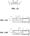
FIG.13A and FIG.13B are cross-sectional views for describing an operation of a current blocking element which is disclosed byPatent Document 2. -
FIG.1 is a cross-sectional view showing the schematic configuration of an ozone generation device inEmbodiment 1 of this invention. InFIG.1 , in a body container of anozone generation device 12, a pair of a cylindrical shapeddielectric tube 1 and a ground metal electrode 11 constitute one discharge tube. InFIG.1 , in order to describe the details of a discharge tube, only two discharge tubes are shown, however, in a large-capacity ozone generation device, in one body container of aozone generation device 12, several hundred discharge tubes are provided. For example, thedielectric tube 1 is comprised of a cylindrical shaped glass tube, the ground metal electrode 11 is comprised of a pipe which is made of stainless, via a spacer which is not shown in FIG., thedielectric tube 1 and the ground metal electrode 11 are disposed concentrically, and between thedielectric tube 1 and the ground metal electrode 11, anarrow discharge gap 25 is formed. One end (right end) of thedielectric tube 1 is closed and other end (left end) of thedielectric tube 1 is opened. In thedielectric tube 1, avoltage applying electrode 2 is disposed. Here, thevoltage applying electrode 2 is comprised of a metal film which is formed by evaporating in an inner surface of thedielectric tube 1. Thedielectric tube 1 having thevoltage applying electrode 2 which is formed on an inner surface thereof and the ground metal electrode 11 constitute a discharge tube. Thevoltage applying electrode 2 is connected to an output end of an ACvoltage generation part 21 in anAC power source 16 via an electrical connectingmember 9, acurrent blocking element 7, apower supplying member 8 and a power supplyinglead wire 14. Other end of the ACvoltage generation part 21 is grounded, and the body container of theozone generation device 12 is also grounded. A part where the power supplyinglead wire 14 is penetrated into the body container of theozone generation device 12 which is ground potential is insulated by abushing 15. An AC voltage which is generated by the ACvoltage generation part 21 of theAC power source 16 is a high voltage which is high enough to generate a discharge in thedischarge gap 25, and frequency of an AC is frequency which can generate discharge via a dielectric, that is, which can generate silent discharge. The ACvoltage generation part 21 generates high frequency AC voltage, for example, voltage is 3 to 7kV and frequency is 0.5 to 5 kHz. - Here, an example of a metal film which is formed in an inner surface of a dielectric as a voltage applying electrode will be described, however, it is not necessary for a voltage applying electrode to be a metal film which is formed on an inner surface, and any metal body which is disposed in the
dielectric tube 1 is acceptable. A configuration in which a voltage is applied between the voltage applying electrode and the ground metal electrode 11 via a dielectric body, in which at any position between a voltage applying electrode and a ground electrode, a discharge gap is formed and in which in the discharge gap, so-called silent discharge is generated is acceptable. - In the
AC power source 16, a powersource control part 22 and an output voltagedrop detection part 23 are provided. InEmbodiment 1, the output voltagedrop detection part 23 is connected between the supplyingpower lead wire 14 and the ground, and based on a signal of the outputvoltage drop detection 23, decrease of an output voltage will be detected and the detected signal will be transmitted to the powersource control part 22. The powersource control part 22 performs controlling of operation or stop of a device and performs monitoring control of an AC power source. The body container of theozone generation device 12 and theAC power source 16 constitute an ozone generation device. - The pipe-shaped ground metal electrode 11 which is made of stainless is connected to end
plates 13 which are provided at both ends thereof by welding, etc., and theend plates 13 are connected to the body container of theozone generation device 12 by welding, etc. The body container of theozone generation device 12 is divided into three rooms by theend plates 13, and the rooms which are positioned at left side and right side are gas space and the room which is positioned at center is filled with coolingwater 24. It is configured for the cooling water to flow from an inlet of coolingwater 19 to an outlet of coolingwater 20. Material gas containing oxygen is introduced from an inlet ofmaterial gas 17, and while the material gas passed through adischarge gap 25, gas is ozonized by discharging and is exhausted from an outlet ofgas containing ozone 18, and is utilized for ozone treatment, etc. -
FIG.2A and FIG.2B are enlarged cross-sectional views showing a configuration of acurrent blocking element 7,FIG.2A is a cross-sectional view in the longitudinal direction of thedielectric tube 1 at a side of a supplying power part andFIG.2B is a cross-sectional view in the lateral direction thereof. At both ends of anintermediate conductor 5b, afuse conductor 5a and afuse conductor 5c are connected, and thefuse conductor 5a, theintermediate conductor 5b and thefuse conductor 5c constitute afusing element 5. At a side of thefuse conductor 5a which is opposite to a side where theintermediate conductor 5b is connected, a fixedelectrode 3 at a side of supplying power is connected. Further, at a side of thefuse conductor 5c which is opposite to a side where theintermediate conductor 5b is connected, a fixedelectrode 4 at a side of voltage applying electrode is connected. The fixedelectrode 3 at a side of supplying power and the fixedelectrode 4 at a side of voltage applying electrode are plate-shaped. As it will be described later, a thickness of the plate may be that of a thin foil, for example, 0.02mm. A surface of the plate of the fixedelectrode 3 at a side of supplying power is fixed to an inner surface of thedielectric tube 1 by a fixingmaterial 3a and a surface of the plate of the fixedelectrode 4 at a side of supplying power is fixed to an inner surface of thedielectric tube 1 by a fixingmaterial 4a, individually. The fixingmaterial 3a and the fixingmaterial 4a are constituted by an adhesive having excellent thermal conductivity, an epoxy-based high thermal conductive adhesive, a conductive adhesive, an inorganic-based adhesive, etc. To the fixedelectrode 4 at a side of voltage applying electrode, an electrical connectingmember 9 is connected, and to the fixedelectrode 3 at a side of supplying power, apower supplying member 8 is connected, individually. InEmbodiment 1, thedielectric tube 1 is provided in a horizontal direction, and as shown inFIG.2B , thecurrent blocking element 7 is provided at an upper side of inside of thedielectric tube 1. - As above mentioned, the
current blocking element 7 comprises afusing element 5 in which thefuse conductor 5a and thefuse conductor 5c are connected to both sides of theintermediate conductor 5b, the plate-shaped fixedelectrode 3 which is connected at a side of thefuse conductor 5a which is opposite to a side where theintermediate conductor 5b is connected, and the plate-shaped fixedelectrode 4 which is connected at a side of thefuse conductor 5c which is opposite to a side where theintermediate conductor 5b is connected, and a plate surface of each fixed electrode is fixed to an inner surface of thedielectric tube 1 by fixing materials. A part of thedielectric tube 1 which constitutes thecurrent blocking element 7 also refers to as a base. Further, a size of a fixed electrode, an intermediate conductor, a fuse conductor and a fixing material shown inFIG.2A and FIG.2B is shown differently from that of actual size ratio against other member of each section, and in order to make the arrangement of each member understandable, in FIG., it is shown such that a size is enlarged, or each member is emphasized. - Next, an operation will be described. When a power
source control part 22 of anAC power source 16 transmits an operation command to an ACvoltage generation part 21, a high frequency AC voltage which is outputted from the ACvoltage generation part 21 is applied to avoltage applying electrode 2 through a power supplyinglead wire 14, thepower supplying member 8, thecurrent blocking element 7 and the electrical connectingmember 9. When a high frequency AC voltage is applied tonarrow discharge gap 25 which is formed between thevoltage applying electrode 2 and the ground metal electrode 11, in thedischarge gap 25, discharge is generated. In many cases, a size of the discharge gap is set to be less than 0.6 mm. When a gas containing oxygen is introduced from the inlet ofmaterial gas 17, the gas passes through thedischarge gap 25, the gas is ozonized by an action of discharge so as to be introduced outside from an outlet ofgas containing ozone 18. A material gas component is dry air or an oxygen gas to which very small amount of nitrogen gas is added. It is necessary for a material gas to contain oxygen at least. A temperature of thevoltage applying electrode 2 and the ground metal electrode 11 are increased due to heat which is generated by discharge, therefore coolingwater 24 is flown through an inlet of coolingwater 19 and an outlet of coolingwater 20 to perform cooling. - In a case where the
dielectric tube 1 is broken down and a hole is generated, a part between thevoltage applying electrode 2 and the ground metal electrode 11 becomes conductive state. As a result, an output side of theAC power source 16 becomes short circuit state, and instantly, a large short circuit current passes through a breakdown part of thedielectric tube 1. A large short circuit current flows in thecurrent blocking element 7 which is provided at thedielectric tube 1 which is broken down. Thefuse conductor 5a and thefuse conductor 5c which constitute thecurrent blocking element 7 have a small sectional area and a high resistance value, therefore when an over current such as a large short circuit current flows instantly in the part, a temperature of the part is increased suddenly, and the part is melted and evaporated. The fuse conductor which is melted and evaporated becomes a high temperature plasma state, and an arc discharge is generated. - Next, a command value of the power
source control part 22 in an operation state or in a breakdown state, waveforms of voltage and current at each part will be shown inFIG.3 . When the powersource control part 22 transmits an operation command, theAC power source 16 becomes an operation state so as to output a high frequency high voltage. When thedielectric tube 1 is broken down, a load side of theAC power source 16 becomes a short circuit state, therefore, a power source output voltage is dropped to be close to zero and at the same time, a large short circuit current will flow in thedielectric tube 1 which is broken down and thecurrent blocking element 7. On the other hand, a voltage which is applied to a normal electrode is dropped to be close to zero, therefore, a current which flows in a normal electrode is dropped to be close to zero, discharge which is generated in thedischarge gap 25 is stopped and generation of ozone is stopped. When an output voltage of theAC power source 16 is dropped to be lower than a predetermined threshold value, an output voltagedrop detecting part 23 detects an output voltage drop and transmits the result to the powersource control part 22. When an output voltage is dropped to be lower than a predetermined threshold even though the state is power source operation state, the powersource control part 22 judges such that a short circuit is generated at a power source output side (short circuit detection) and transmits an operation stop command to the ACvoltage generation part 21. As a result, theAC power source 16 stops an output, a power source output voltage is dropped to be zero, and a large short circuit current which flows in an electrode which is broken down is dropped to be zero. An arc discharge which is generated in thefuse conductor 5a and thefuse conductor 5c is extinguished when a large short circuit current is dropped. Thefuse conductor 5a and thefuse conductor 5c shown inFIG.2A are extinguished by melting, as a result, theintermediate conductor 5b loses supporting at both ends, and therefore, as shown inFIG.4 , theintermediate conductor 5b is dropped to a bottom of inside of thedielectric tube 1. Between the fixedelectrode 3 at a power supplying side and thevoltage applying electrode 2, an insulation distance shown inFIG.4 is secured. -
- (a) An insulation distance between the fixed
electrode 3 at a power supplying side and the fixedelectrode 4 at a voltage applying electrode side = L1 - (b) An insulation distance between the fixed
electrode 3 at a power supplying side and the fixedelectrode 4 at a voltage applying electrode side via theintermediate conductor 5b = L2 + L3 - (c) An insulation distance between the fixed
electrode 3 at a power supplying side and thevoltage applying electrode 2 via theintermediate conductor 5b = L2 + L4 - In any of (a), (b) or (c), an insulation distance is sufficiently secured, therefore even when high frequency high voltage is applied to the fixed
voltage 3 at a power supplying side again, an arc discharge will not be generated in a part where the above mentioned insulation distance is indicated. Regarding general ozone generation devices, in many cases, an effective value of applying voltage is 7.5kV or lower, further, in many cases, an ozone generation device will be operated in which gas pressure inside the body container of anozone generation device 12 is 0.07 MPa or higher. In the above mentioned case, when an insulation distance = 7mm or larger, an arc discharge will not be generated when a voltage is applied again. However, when an ozone generation device is used for a long period, an inner surface of thedielectric tube 1 is stained, in some cases, an insulation performance is deteriorated, therefore it is preferable such that an insulation distance is 14mm or larger, that is the twice of the above mentioned distance. Further, in a case where an operation voltage of an ozone generation device is low, for example, in a case of 4kV, by making an insulation distance 4mm or larger, a size of a current blocking element can be reduced further. - After the power
source control part 22 transmits an operation stop command, and then as shown inFIG.3 , the powersource control part 22 transmits an operation restart command to the ACvoltage generation part 21, and theAC power source 16 outputs a high frequency high voltage again. A period of time from operation stop command to operation restart command is predetermined. The above mentioned period of time may be set as a period of time which is longer than continuing time of an arc discharge which is generated in thefuse conductor 5a and thefuse conductor 5c. The above mentioned predetermined period of time is for example, 1 to 10 seconds. In an electrode which is broken down, thefuse conductor 5a and thefuse conductor 5c are melted and evaporated, and theintermediate conductor 5b is dropped to a bottom of thedielectric tube 1 and electrically cut off, therefore, a current does not flow. In a normal electrode, a high frequency high voltage is applied, a current flows, a discharge is generated in thedischarge gap 25, and generation of ozone is started again. When the number ofdielectric tubes 1 which are arranged in the body container of anozone generation device 12 is indicated as N, an amount of generation of ozone is decreased to roughly [(N-1)/N]. In an ozone generation device having many dielectric tubes, for example, N= several hundreds, an output decrease ratio will be lowered. - As above mentioned, by detecting voltage drop due to breakdown of a
dielectric tube 1, stopping theAC power source 16 so as to drop a large short circuit current to be zero, electrically cutting off thedielectric tube 1 which is broken down by thecurrent blocking element 7 and restarting theAC power source 16, an operation of an ozone generation device can be continued. By doing the above mentioned, protection (short circuit protection) in a case where a short circuit is generated at a load side of theAC power source 16 can be performed. - In the above mentioned, as a method for detecting breakdown of a dielectric tube, that is, breakdown of a discharge tube, a case in which a drop of output voltage is detected by measuring by the output voltage
drop detection part 23 which is provided in an AC power source is described, however, when breakdown of discharge tube is detected by using other methods, for example, a method for detecting an increase of output current, a method in which a plurality of discharge tubes are divided into two and output of power sources is divided into two so as to apply a current and detect by difference of current value, and a method in which light which is emitted from an arc discharge in a body container of an ozone generation device is measured, breakdown of a discharge tube is detected so as to control an output of theAC power source 16, same effect can be obtained. - Next, heat generation and cooling in the
current blocking element 7 inEmbodiment 1 will be described. A value of current which flows in thecurrent blocking element 7 in normal operation (value of current per one dielectric tube) is 0.2 to 1A in a case where a typical voltage which is applied to an ozone generation device is 3 to 7 kV. On the other hand, a value of current of over current (short circuit current) when thedielectric tube 1 is broken down depends on an impedance of AC power source, however, a value of current is approximately 10 times to 1000 times of a value of current in operation. A value of resistance between terminals of thecurrent blocking element 7 depends on a size and material of thefuse conductor 5a and thefuse conductor 5c, and when a cross-sectional area is indicated by S, a length is indicated by L and a resistance ratio is indicated by p, a value of resistance of one fuse conductor :R=ρ x (L/S). In order to make thecurrent blocking element 7 function, it is necessary to increase a temperature which is higher than a temperature by which thefuse conductor 5a and thefuse conductor 5c are melted by a flow of overcurrent. As a short circuit current flows momentarily, Joule heat which is generated in a fuse conductor will not be dissipated to the circumference, and heats the fuse conductors. Consequently, whether a fuse conductor is melted or not is determined by a melting temperature, a specific gravity, a specific heat, a resistance ratio ρ and a cross-sectional area S which are determined by a material of a fuse conductor. - In
Embodiment 1, as a material of thecurrent blocking element 7, stainless steel (SUS304 or SUS316) is used and regarding a cross-sectional size of thefuse conductor 5a and thefuse conductor 5c, a thickness is 0.01 to 0.05mm and a width is 0.05 to 0.30mm. When a length of thefuse conductor 5a and thefuse conductor 5c is shorter, a value of resistance R is smaller and generated heat due to current in operation is smaller, further, when a length is shorter, heat which is generated by current in operation in thefuse conductor 5a and thefuse conductor 5c transmits more easily to the fixedelectrode 3 at power supplying side and the fixedelectrode 4 at voltage applying electrode side, and a temperature of the fuse conductor is dropped. One of the features inEmbodiment 1 is such that by fixing a surface of the fixedelectrode 3 and that of the fixedelectrode 4 to an inner surface of thedielectric tube 1 via the fixingmaterial 3a and the fixingmaterial 4a, heat which is generated in a fuse conductor in normal operation is radiated from the fixedelectrode 3 and the fixedelectrode 4 through thedielectric tube 1. InEmbodiment 1, a length of a fuse conductor is set to be 1mm. When a length is extremely short, for example, less than 0.1mm, heat will be extremely escaped from a fuse conductor to a fixed electrode at power supplying side or to a fixed electrode at voltage applying electrode side, therefore a fuse conductor is not melted easily due to a short circuit current, and after a short circuit current becomes zero, the melted part is fixed again, and consequently, a problem, that is, a fuse conductor part is electrically connected, will occur. On the other hand, when a length of a fuse conductor is longer, an amount of generation heat in a fuse conductor is increased, and circuit loss is increased, therefore an ozone generation ratio will be decreased. Further, a temperature of a fuse conductor in operation will be increased, therefore, when a device is operated for a long period, disconnection in a fuse conductor due to material deterioration is generated easily. Consequently, regarding a length of a fuse conductor, in a case where SUS304 or SUS316 is used, a length of 0.1 to 2mm is most appropriate. When a fuse conductor having a length of 0.1 to 2mm is used and a short circuit current is flown, in a case of a short circuit current 10A, a fuse conductor is fused at 5 to 0.15ms and in a case of a short circuit current 100A, a fuse conductor is fused at 50 to 1.5 µs. - A plate surface of the fixed
electrode 3 and that of the fixedelectrode 4 are fixed to an inner surface of thedielectric tube 1 via the fixingmaterial 3 and the fixingmaterial 4, individually, and from the fixedelectrode 3 and the fixedelectrode 4 to thedielectric tube 1, heat is radiated due to heat conduction in the entire surface which is fixed. Heat is radiated from surface, therefore, an amount of radiation can be increased. Further, in order not to prevent radiation from the fixedelectrode 3 and the fixedelectrode 4 to thedielectric tube 1, as the fixingmaterial 3a and the fixingmaterial 4a, an adhesive having excellent heat conduction is used. Concretely, an epoxy based excellent heat conduction adhesive or a conductive adhesive may be used. Further, when non-organic based adhesives or general adhesives is used, by applying them thinly, heat conduction can be increased. When a current in normal operation flows in thecurrent blocking element 7, heat which is generated in theheat conductor 5a is immediately conducted to thedielectric tube 1 through the fixedelectrode 3 at power supplying side and the fixingmaterial 3a. Heat which is conducted to thedielectric tube 1 is expanded widely in thedielectric tube 1, and by heat transfer, heat is radiated to the surrounding gas. In a case where a glass tube is used as thedielectric tube 1, when a thickness of the glass tube is 1 to 3mm, heat is conducted in the dielectric tube immediately, therefore, heat is conducted widely and immediately in thedielectric tube 1. Regarding heat transfer, when a surface area is larger, performance for conducting heat is more excellent, therefore, by making the above mentioned configuration, temperature increase of thefuse conductor 5a can be suppressed. As a result, material deterioration due to temperature increase can be suppressed, therefore disconnection of thefuse conductor 5a due to material deterioration can be suppressed, consequently, thecurrent blocking element 7 which is highly reliable can be provided. In the same way as the above mentioned, heat which is generated in thefuse conductor 5c is conducted immediately to thedielectric tube 1 through the fixedelectrode 4 at voltage applying electrode side and the fixingmaterial 4a, and heat is radiated. Further, regarding a thickness of an adhesive which is used as the fixingmaterial 3a and the fixingmaterial 4a, when a thickness of an adhesive is thinner, heat is conducted to the dielectric tube more easily. - Further, an objective of the fixed
electrode 3 at power supplying side and the fixedelectrode 4 at voltage applying electrode side is to transmit efficiently heat which is generated in thefuse conductor 5a and thefuse conductor 5c to thedielectric tube 1 by fixing with surface, therefore, when a size is too small, a temperature is increased, however, it is not necessary to make a size larger. This is because such that even when an area of surface where thedielectric tube 1 is fixed is small, due to a function of the fixingmaterial 3a and the fixingmaterial 4a which have excellent head conduction, heat which is generated in the fuse conductor can be transmitted efficiently to thedielectric tube 1. InEmbodiment 1, regarding a size of the fixedelectrode 3 at power supplying side and that of the fixedelectrode 4 at voltage applying electrode side, a thickness is 0.01 to 0.05mm, a width is 1.5 to 6mm, and a length is 2 to 16mm. Regarding the above mentioned fixed electrodes, a surface which is formed to have a width 1.5 to 6mm and alength 2 to 16mm is fixed to an inner surface of thedielectric tube 1 which constitutes a base of a current blocking element by a fixing material. - It is necessary to make a cross-sectional area of the
intermediate conductor 5b larger than that of thefuse conductor 5a and that of thefuse conductor 5c for suppressing Joule heating by a current in normal operation. On the other hand, when a cross-sectional area of theintermediate conductor 5b is too large, weight of theintermediate conductor 5b is applied to thefuse conductor 5a and thefuse conductor 5c which are provided at both sides of theintermediate conductor 5b, and mechanical stress which is applied to the fuse conductors becomes large, therefore disconnection of fuse conductors due to mechanical stress is generated easily. From the above mentioned view point, regarding a cross-sectional size of theintermediate conductor 5b, a thickness is 0.01 to 0.05mm and a width is 0.5 to 5mm. A length of theintermediate conductor 5b is set to be 4 to 8mm for securing an insulation size. Further, a thickness of the fixingmaterial 3a and the fixingmaterial 4a is set to be 0.01 to 0.5mm and L4 size inFIG.3 is set to be 1 to 5mm. By making the above mentioned configuration, an insulation size shown inFIG.4 will be the following inEmbodiment 1. -
- (a)

- (b)

- (c)

- In a case where an inner diameter of a glass tube which constitutes the
dielectric tube 1 is 4mm or more, an insulation size of the (a) to (c) is 4mm or more which is necessary insulation size, therefore insulation can be secured. Regarding a length of theintermediate conductor 5b, in order to satisfy the above mentioned, when a length is shorter, generation heat in theintermediate conductor 5b can be suppressed more. - In conventional example shown in
FIG.12 , when a current blocking element is designed to have two fuse conductors, before a current blocking element functions, the configuration isFIG.13A , and after a current blocking element functions, the configuration isFIG. 13B . After a current blocking element functions, an insulation distance is secured at (L1+L2), however, when it is compared toFIG.4 inEmbodiment 1, in conventional example, anelectrode 33 and anelectrode 34 are disposed in the center of thedielectric tube 1, therefore, in a case of a glass tube having the same diameter, a dropping distance becomes half, and an insulation distance (L1+L2) becomes short. Consequently, in order to secure necessary insulation distance, it is necessary to secure enough distance between theelectrode 33 and theelectrode 34. Further, as can be understood from the position relationship inFIG. 13A and FIG.13B , sum of a length of twofuse conductors 36 is a dominant size which determines an insulation distance (L1+L2). Consequently, in order to secure an insulation distance 7mm or more, it is necessary to secure lengths of thefuse conductors 36 to be 3.5mm or more, individually, and when it is compared to a size of a fuse conductor inEmbodiment 1, that is, 1mm, it is 3.5 times longer. As a result, inEmbodiment 1, a value of resistance of a fuse conductor is decreased to be 1/3.5=28.6%, and fuse conductor generating heat is decreased to be 28.6%. - As above mentioned, by suppressing heat generation of a fuse conductor, and by fixing a plate surface of a fixed electrode to an inner surface of a dielectric tube, heat radiation can be improved, therefore a temperature increase of a fuse conductor, an intermediate conductor and a fixed electrode in normal operation is decreased, as a result, thermal stress which is applied to a fuse conductor is decreased, and disconnection of a fuse conductor due to thermal stress in normal operation will not be generated.
- Further, the configuration is made such that when a fuse conductor is melted, the
intermediate conductor 5b will be dropped to a bottom of thedielectric tube 1, therefore, it is easier to secure an insulation distance. In order to secure an insulation distance, thecurrent blocking element 7 may be attached for a fixed electrode to be fixed at a position where in a case where a fuse conductor is melted, a distance between a fixed electrode and theintermediate conductor 5b after theintermediate conductor 5b is dropped due to gravity is larger than that before theintermediate conductor 5b is dropped. In a case where thedielectric tube 1 is installed for a tube axis direction of the dielectric tube to be horizontal, in order to make theintermediate conductor 5b drop to a bottom of thedielectric tube 1, thecurrent blocking element 7 may be installed so as for a normal vector which is from at least a part of a surface of thedielectric tube 1 at which a fixed electrode is fixed to a side where a fixed electrode is fixed has a component of gravity direction. Further, in a case where thedielectric tube 1 is cylindrical shape and is installed so as for a tube axis direction to be horizontal direction, above mentioned condition is for a fixed electrode to be fixed at any position of upper side half of an inner surface of the dielectric tube. - Heat generation of a fuse conductor in normal operation is suppressed and heat dissipation is improved, therefore, a size of a fixed electrode can be decreased and the configuration is such that the
intermediate conductor 5b is dropped to a bottom of thedielectric tube 1 while the fuse conductor is fused, consequently, an insulation distance can be secured easily. Therefore, even a size of tube diameter of a glass tube is decreased, a temperature increase of a fuse conductor in normal operation can be suppressed, and an insulation function can be secured after a fuse conductor is fused. As a result, a size of a tube diameter of thedielectric tube 1 can be decreased, loading of thedielectric tubes 1 with high density to a container of a body of an ozone generation device can be performed, and an ozone generating device which is compact can be provided at a lower cost. - Further, heat generation of a fuse conductor in normal operation is decreased, therefore, loss of electric circuit when an ozone is generated is decreased, and therefore, an ozone generation efficiency is improved. Further, heat generation of a fuse conductor is decreased, a gas temperature increase when a material gas is introduced from a
material gas inlet 17 to thedischarge gap 25 is decreased, therefore a temperature increase at an inlet part of a discharge gap part is suppressed, and therefore an ozone generation efficiency is improved. - In the above mentioned, a case in which the
current blocking element 7 is attached to upper part of inner part of a dielectric is shown, however, by attaching thecurrent blocking element 7 to a position which is upper half inside a dielectric, an intermediate conductor will be dropped, an insulation distance can be made large, and an effect can be obtained. - Further, a case in which between the fixed
electrode 4 at voltage applying electrode side and thevoltage applying electrode 2 is connected by the electrical connectingmember 9 is shown, however, the electrical connectingmember 9 may be omitted and the fixedelectrode 4 at voltage applying electrode side may be directly electrically connected on thevoltage applying electrode 2. - Further, in the above mentioned, the
current blocking element 7 is attached to a position which is upper half of thedielectric tube 1, however, when thecurrent blocking element 7 is attached to a position which is lower half of thedielectric tube 1, an insulation distance after a fuse conductor is melted and evaporated becomes shorter, however, there is an effect such that heat generation of a conductor in normal operation can be dissipated from large surface of thedielectric tube 1 via the fixedelectrode 3 at power supplying side and the fixedelectrode 4 at voltage applying electrode side which are fixed to thedielectric tube 1 to surrounding gas due to heat transfer. Consequently, in a case where an operation voltage of an ozone generation device may be low and insulation distance may be low, thecurrent blocking element 7 which has excellent cooling performance can be realized. -
FIG.5 is a cross-sectional view showing a principal part of adielectric tube 1 inEmbodiment 2 of this invention. InEmbodiment 1, a case in which onefusing element 5 is used is described, however, when two fusing elements per onecurrent blocking element 7 are used, reliability of a device can be improved. Concretely, as shown inFIG.5 , at both sides of anintermediate conductor 51b, afuse conductor 51a and afuse conductor 51c are connected so as to constitute a fusingelement 51, and at both sides of anintermediate conductor 52b, afuse conductor 52a and afuse conductor 52c are connected so as to constitute a fusingelement 52. Between a fixedelectrode 3 at power supplying side and a fixedelectrode 4 at voltage applying electrode side, an intermediatefixed electrode 6 is disposed, between the fixedelectrode 3 at power supplying side and the intermediate fixedelectrode 6, the fusingelement 51 is connected, and between the fixedelectrode 4 at voltage applying electrode side and the intermediate fixedelectrode 6, the fusingelement 52 is connected. The intermediatefixed electrode 6 is fixed to adielectric tube 1 by a fixingmaterial 6a which has excellent heat conductivity. The fixedelectrode 3 at power supplying side, the fusingelement 51, the intermediate fixedelectrode 6, the fusingelement 52, the fixedelectrode 4 at voltage supplying electrode side and a part of thedielectric tube 1 where the above mentioned fixed electrodes are fixed constitute acurrent blocking element 7. - Heat which is generated in the
fuse conductor 51a by a current which flows in thedielectric tube 1 in operation is conducted to thedielectric tube 1 through the fixedelectrode 3 at power supplying side and the fixingmaterial 3a, heat which is generated in thefuse conductor 51c and thefuse conductor 52a is conducted to thedielectric tube 1 through the intermediate fixedelectrode 6 and the fixingmaterial 6a, heat which is generated in thefuse conductor 52c is conducted to thedielectric tube 1 through the fixedelectrode 4 at voltage applying electrode side and the fixingmaterial 4a, and the heat is efficiently radiated from a wide surface of thedielectric tube 1 by heat transfer to surrounding gas. - When a short circuit current flows in the
current blocking element 7, thefuse conductors FIG.6A , theintermediate conductors dielectric tube 1. - As will be described in the following, in some cases, a fusing element operates abnormally, therefore, when the
current blocking element 7 is constituted by two fusing elements, reliability can be improved. - (1) As a width of a fuse conductor is small, due to variation of manufactured size, in a case where a short circuit current is small, a fuse conductor may not be fused.
- (2) In a case where a fuse conductor or a part of an intermediate conductor is melted and when the intermediate conductor is close to a dielectric, the fuse conductor or a part of an intermediate conductor may be welded to the dielectric. In the above mentioned case, an intermediate conductor will not drop down, therefore an insulation distance is short and in a case where a voltage is applied again, short circuit will be occurred again. In a case where one of two fusing elements does not function, in order to make the current blocking element function, it is preferable for the configuration of the fusing
element 51 and that of the fusingelement 52 is matched to that of thefusing element 5 inEmbodiment 1. -
FIG.6A shows the state in a case where both of the fusingelement 51 and the fusingelement 52 drop. An insulation distance will be as follows. - (a) An insulation distance between the fixed
electrode 3 at power supplying side and the fixedelectrode 4 at voltage applying electrode side = L1 + L2 - (b) An insulation distance between the fixed
electrode 3 at power supplying side and the fixedelectrode 4 at voltage applying side via theintermediate conductor - (c) An insulation distance between the fixed
electrode 3 at power supplying side and thevoltage applying electrode 2 via theintermediate conductor - When the configuration of the fusing
element 51 and that of the fusingelement 52 are matched to that of thefusing element 5 inEmbodiment 1, an insulation distance will be 1.5 to 2 times longer than that of a case inEmbodiment 1, therefore, an insulation function can be sufficiently performed. -
FIG.6B shows the state in a case where the fusing element does not function normally, only the fusingelement 52 functions normally and only the fusingelement 52 drops. When the configuration of the fusingelement 51 and that of the fusingelement 52 are matched to that of thefusing element 5 inEmbodiment 1, an insulation distance in this case will be same as that inEmbodiment 1. By configuring as above mentioned, in a case where a short circuit current flows, even when one fusing element, that is, the fusingelement 51 does not function normally, other fusing element, that is, the fusingelement 52 functions normally, therefore, an insulation distance can be secured only by the fusing element at one side, consequently, reliability of short circuit protection function can be improved. In the above mentioned, a case in which two fusing elements are used is described, however, when the number of fusing elements are increased more, reliability of short circuit protection function can be improved further. - Further, in the Embodiment, it is preferable such that the configuration of the fusing
element 51 and that of the fusingelement 52 are matched to that of thefusing element 5 inEmbodiment 1, however, when it is designed to satisfy necessary insulation distance (4mm or more) by an insulation distance which is made by dropping of a plurality of fusing elements, the same effect can be realized. Regarding concrete design, with regard to L1, L2, L3, L4, L5 and L6 inFIG.6A , it is acceptable for all of following (a), (b) and (c) to be 4mm or more. -
- (a) An insulation distance between the fixed
electrode 3 at power supplying side and the fixedelectrode 4 at voltage applying electrode side = L1 + L2 - (b) An insulation distance between the fixed
electrode 3 at power supplying side and the fixedelectrode 4 at voltage applying electrode side via theintermediate conductor - (c) An insulation distance between the fixed
electrode 3 at power supplying side and thevoltage applying electrode 2 via theintermediate conductor -
FIG.7 is a cross-sectional view showing a principal part of adielectric tube 1 of an ozone generation device inEmbodiment 3 of this invention. InEmbodiment 1, an edge part of thedielectric tube 1 whose side where power is applied by apower applying member 8 is opened, however, as shown inFIG.7 , ametallic cap 29 is attached to an open part of thedielectric tube 1 and between afixed electrode 3 at power supplying side and thecap 29 is electrically connected by a connectingconductor 26, and thepower supplying member 8 is electrically connected to thecap 29. When a short circuit current flows in acurrent blocking element 7, in some cases, afuse conductor 5a and afuse conductor 5c are melted and scattered, and anintermediate conductor 5b is scattered by arc discharge and escaped outside from an open part of thedielectric tube 1, and they are attached to a surface of other dielectric and electrical insulation can not be maintained. By attaching thecap 29, thefuse conductor 5a, thefuse conductor 5c and theintermediate conductor 5b will not be scattered outside a dielectric, therefore reliability of an ozone generation device can be improved. Regarding fixing of thecap 29 to thedielectric tube 1, any method such as caulking ofcap 29, applying an inorganic adhesive to inside a cap, etc. is acceptable. -
FIG.8 is an enlarged cross-sectional view showing the configuration of a current blocking element which is provided at an ozone generation device inEmbodiment 4 of this invention. InEmbodiment 1, a case in which a fusing element is attached to an inner surface of adielectric tube 1, however, as shown inFIG.8 , it may be configured such that afusing element 5 is attached to roughly upper side of an inner surface of adielectric member 27 which has a cylindrical shape, at openings which are provided at both sides of thedielectric member 27, ametallic cap 29a and ametallic cap 29b are attached, a fixedelectrode 3 at power supplying side and thecap 29a are electrically connected by a connectingconductor 26a, a fixedelectrode 4 at voltage supplying electrode side and thecap 29b are electrically connected by a connectingconductor 26b, and acurrent blocking element 7 is constituted independently from thedielectric tube 1. In this case, a part of thedielectric member 27 which has a cylindrical shape constitutes a base of thecurrent blocking element 7. According to a current blocking element inEmbodiment 4, thecurrent blocking element 7 can be manufactured at a manufacturing process which is different from that of thedielectric tube 1 and thevoltage applying electrode 2, therefore a fuse manufacturing process can be made easier and manufacturing cost can be decreased. - In the above mentioned, a method for installing the
dielectric member 27 which constitutes a base of thecurrent blocking element 7 outside thedielectric tube 1 is described, however, thedielectric member 27 which constitutes a base of thecurrent blocking element 7 may be disposed inside thedielectric tube 1. Further, among caps which are provided at both ends, one and both of them may be omitted. - Further, in
FIG.8 , thedielectric member 27 has a cylindrical shape, however, thedielectric member 27 may have different shape, for example, thedielectric member 27 is formed to be a dielectric plate which is made of glass or ceramic, and the plate shapeddielectric member 27 is used as a base so as to constitutes thecurrent blocking element 7. In the above mentioned case, same effect can be realized. Further, when the above mentioned structure is attached to inside thedielectric tube 1, same effect can be realized. -
FIG.9 is an enlarged cross-sectional view showing the configuration of a current blocking element which is provided at an ozone generation device inEmbodiment 5 of this invention. As shown inFIG.9 , acurrent blocking element 7 which is constituted to have a plate shapeddielectric member 27 as a base may be disposed inside anothersecond dielectric member 28 having a tubular shape. Thedielectric member 27 which constitutes a base of thecurrent blocking element 7 is fixed to thesecond dielectric member 28 by a method which is not shown in FIG. At opening parts which are provided at both sides of thedielectric member 28, ametallic cap 29a and ametallic cap 29b are attached to, between afixed electrode 3 at power supplying side and thecap 29a is electrically connected by a connectingconductor 26b, and between afixed electrode 4 at voltage applying electrode side and thecap 29b is electrically connected by a connectingconductor 26b. Heat which is generated in afuse conductor 5a and afuse conductor 5b is dissipated from thedielectric member 27 via the fixedelectrode 3 at power supplying side and the fixedelectrode 4 at voltage applying electrode side, and once temperature of gas inside thesecond dielectric member 28 having a tubular shape is raised, and the heat is dissipated from a surface of thesecond dielectric member 28 to outside gas by heat transfer. The dissipated heat is indirection, therefore, dissipation ratio becomes worse in comparison withEmbodiments 1 to 4, however, thecurrent blocking element 7 can be manufactured in a manufacturing process which is different from that of thedielectric tube 1, thevoltage applying electrode 2 and thesecond dielectric member 28 having a tubular shape, consequently, a fuse manufacturing process can be made easier and manufacturing cost can be decreased. - In the Embodiment, a method for installing the
second dielectric member 28 outside thedielectric tube 1 is described, however, thesecond dielectric member 28 may be disposed inside thedielectric tube 1. Further, among caps which are provided at both sides, one and both of them may be omitted. - Further, regarding a material of a fuse conductor, even when a fuse conductor having a material other than stainless steel (SUS304) is manufactured to have designed size, the same effect can be realized. However, in a case where it is considered such that a fuse conductor is easily chemically reacted to oxygen gas, NOx gas which is generated by discharge and a fuse conductor is deteriorated for a long period, by attaching the
cap 29, the same effect can be realized. - In
Embodiments 1 to 5, an ozone generation device in which a discharge tube having the electrode configuration in which thevoltage applying electrode 2 is disposed inside thedielectric tube 1 is described, however, as a discharge tube of an ozone generation device by silent discharge, a discharge tube having the electrode configuration in which a dielectric made of enamel covers the surroundings of metallic voltage applying electrode may exist. In a case of the above mentioned electrode configuration, a current blocking element, which has a base of a dielectric which is different from a dielectric which constitutes a discharge tube shown inFIG.8 andFIG.9 , which is described inEmbodiment 4 andEmbodiment 5, can be applied, and the same effect as that ofEmbodiment 4 andEmbodiment 5 can be realized. - Further, the configuration of a discharge tube in which an inner surface of a ground metallic electrode is coated with a dielectric, a discharge gap is formed inside the dielectric coating and a metallic voltage applying electrode is disposed may exist. In a case of the above mentioned configuration of a discharge tube, a current blocking element, which has a base of a dielectric which is different from a dielectric which constitutes a discharge tube shown in
FIG.8 andFIG.9 , which is described inEmbodiment 4 andEmbodiment 5, can be applied, and the same effect as that ofEmbodiment 4 andEmbodiment 5 can be realized. As above mentioned, in a case where a current blocking element shown inFIG.8 andFIG.9 is applied, as a discharge tube, when the configuration is such that by applying high frequency AC voltage between a voltage applying electrode and a ground metallic electrode, silent discharge is generated via a dielectric, any configuration is acceptable, and the same effect as that ofEmbodiment 4 and that ofEmbodiment 5 can be realized. -
FIG.10A and FIG.10B are plan views showing the configuration of ametallic member 100 where a current flows of acurrent blocking element 7 inEmbodiment 6 of this invention in which a base of a dielectric and a fixing material are eliminated. Themetallic member 100 can be applied to a metallic member of a current blocking element inEmbodiments 1 to 5. InEmbodiments 1 to 5, whole of a metallic member where a current flows can be manufactured by etching a metallic plate having a thin thickness, that is, a metallic foil to form integrally. As above mentioned, by manufacturing a current blocking element by etching whole of a metallic member to form integrally, cost for manufacturing a current blocking element can be decreased drastically, further, a small sectional shape of a fuse conductor can be processed precisely, therefore variation of performance of a current blocking element can be suppressed, as a result, an ozone generation device having high reliability can be provided.FIG.10A is a plan view showing the configuration having one fusingelement 5, and shows the configuration which is produced by etching whole of a metallic member in which a fixedelectrode 3 at power supplying side, a fusing element 5 (afuse conductor 5a, anintermediate conductor 5b, afuse conductor 5c) and a fixedelectrode 4 at voltage applying electrode side are connected in this order to form integrally. Further,FIG.10B is a plan view showing the configuration having two fusing elements, and shows the configuration which is produced by etching whole of a metallic member in which a fixedelectrode 3 at power supplying side, a fusing element 51 (afuse conductor 51a, anintermediate conductor 51b, afuse conductor 51c), a fusing element 52 (afuse conductor 52a, anintermediate conductor 52b, afuse conductor 52c) and a fixedelectrode 4 at voltage applying electrode side are connected in this order to form integrally. - Especially, when stainless steel (SUS304, etc.) is used as a material, cost of material is comparably cheap, and even when a material having a thin thickness such as 0.15mm is used, handling at manufacturing can be performed. Fusing performance is determined by sectional area of a fuse conductor, therefore, when a thickness of a material is thinner, a necessary width of a fuse conductor is wider, consequently, processing can be performed precisely. For example, in a case of SUS304 material having a thickness of 0.02mm, a width of a fuse conductor is 0.15mm, and by etching process, a conductor width can be processed precisely. When a silver material which is often used for a fuse is used, a resistivity of silver is low, therefore when a fuse conductor having the same thickness of 0.02mm is designed, a fuse conductor width is 0.006mm, the fuse conductor can not be processed precisely, therefore, it is necessary to apply microfabrication for a semiconductor, as a result, process cost will be increased drastically. From the above mentioned point of view, in a case where a current blocking element of an ozone generation device is manufactured by etching process whose manufacturing cost is cheap, a metallic material having a resistivity which is close to that of stainless steel (70µΩ · cm) is appropriate. A fuse conductor is increased in temperature due to current conduction and is deteriorated by oxidizing with oxygen gas, therefore a material which is not deteriorated easily, such as stainless steel, is preferable for improving a reliability of a current blocking element.
- In
FIG.10A and FIG.10B . for example, in a case where a stainless steel (SUS304, etc.) having a thickness of 0.02mm is used, regarding a size of the fixedelectrode 3 at power supplying side, the fixedelectrode 4 at voltage applying electrode side, the intermediate fixedelectrode 6, for example, a width is 1.5 to 6mm, a length is 2 to 16mm. Further, regarding a size of anintermediate conductor 5b, anintermediate conductor 51b and anintermediate conductor 52b, for example, a width is 0.5 to 5mm and a length is 3 to 8mm. By fixing a surface of a fixed electrode, having a width 1.5 to 6mm and a length of 2 to 16mm which is manufactured by using a metallic member which is made of stainless foil which is processed by etching to have the above mentioned size, on a base of a dielectric by a fixing material, a current blocking element is constituted. As above mentioned, by using a metallic member which is manufactured by processing by etching a stainless foil, a current blocking element which has small variation of performance and high reliability can be provided. - In
Embodiment 5, in a case where acurrent blocking element 7, which is constituted by a transparent glass as asecond dielectric member 28, functions, it can be confirmed visually such that anintermediate conductor 5b drops to a bottom inside thesecond dielectric member 28. After an ozone generation device is used for a long period, when a body container of anozone generation 12 is opened so as to inspect inside the device, a fuse part of thesecond dielectric member 28 is confirmed visually, and when an intermediate conductor drops, we can confirm such that thecurrent blocking element 7 functions. When inside of thesecond dielectric member 28 can not see, it is necessary to confirm whether thecurrent blocking element 7 functions or not by measuring a resistive value between thecap 29a and thecap 29b, however, when thesecond dielectric member 28 is constituted by a transparent glass, we can confirm the operation of thecurrent blocking element 7 visually, that is, work is easier. Thedielectric tube 1 to which a fuse which functions is attached is broken down, therefore, it is necessary to replace the dielectric tube during maintenance, therefore, thedielectric tube 1, thevoltage applying electrode 2 and thecurrent blocking element 7 are taken out to replace with new ones. As above mentioned, when thecurrent blocking element 7 inEmbodiment 7 is used, there is an effect such that maintenance of an ozone generation device can be performed easily. - Further, in addition to the
second dielectric member 28 inEmbodiment 5, when the dielectric tube inEmbodiment 1,Embodiment 2 andEmbodiment 3, thedielectric member 27 in theEmbodiment 4 are constituted by a transparent glass tube, dropping of an intermediate conductor can be confirmed visually, therefore the same effect can be realized. - In
Embodiments 1 to 7, a case in which a discharge tube is installed in a horizontal direction is described, however, in a case where a discharge tube is installed vertically, that is an axial direction of a discharge tube is to be the direction of gravity, thecurrent blocking element 7 may be attached toward a vertical direction. Further, in a case where a discharge tube is constituted by a dielectric tube in which one side is opened as shown inFIG.1 , an opening part is disposed at an upper side of vertical direction of a dielectric tube, and a current blocking element may be attached to the vicinity of the opening part. - Further, within the scope of this invention, each embodiment may be combined, and each embodiment may be appropriately deformed or omitted.
-
- 1
- dielectric tube
- 2
- voltage applying electrode
- 3
- fixed electrode at power supplying side
- 4
- fixed electrode at voltage applying electrode side
- 3a, 4a, 6a
- fixing material
- 5, 51, 54
- fusing element
- 5a, 5c, 51a, 51c, 52a, 52c
- fuse conductor
- 5b, 51b, 52b
- intermediate conductor
- 6
- intermediate fixed electrode
- 7
- current blocking element
- 11
- ground metal electrode
- 16
- AC power source
- 100
- metallic member
Claims (16)
- A current blocking element having a configuration such that at each side of both ends of a fusing element having a configuration such that a fuse conductor which is melted by overcurrent is connected to both sides of an intermediate conductor, individually, a fixed electrode having plate shape is connected, and a plate surface of each fixed electrode is fixed to a surface of a base of a dielectric by a fixing material.
- The current blocking element according to claim 1, wherein three or more of the fixed electrodes are provided, and between the adjoining fixed electrodes, each of the fusing elements is connected.
- The current blocking element according to claim 1 or 2, wherein the base is tubular, and the fixed electrode is fixed to an inner surface of the base.
- The current blocking element according to claim 1 or 2, wherein the base having the fusing element is installed at inside of a tubular dielectric.
- The current blocking element according to any of claims 1 to 4, wherein a metallic member which is a connection body of the fixed electrodes and the fusing element is formed by one metallic plate.
- An ozone generation device comprising a plurality of discharge tubes in which each discharge tube has a discharge gap between a voltage applying electrode and a ground metal electrode via a dielectric and
having a configuration in which gas containing oxygen is flown in the discharge gap, by applying an AC voltage from an AC power source to between the voltage applying electrode and the ground metal electrode, the gas containing oxygen is discharged to be an ozonized gas,
wherein a current blocking element which is claimed in any one of claims 1 to 5 is connected between the AC power source and each of the voltage applying electrodes of a plurality of discharge tubes, individually. - The ozone generation device according to claim 6, wherein the current blocking element is attached so as for the fixed electrode to be fixed at a position where in a case where the fuse conductor is melted, a distance between the fixed electrode and the intermediate conductor after the intermediate conductor is dropped due to gravity is larger than a distance between the fixed electrode and the intermediate conductor before the intermediate conductor is dropped.
- The ozone generation device according to claim 7, wherein the current blocking element is installed so as for a normal vector which is from at least one surface of the base at which the fixed electrode is fixed to a side where the fixed electrode is fixed has a component of gravity direction.
- An ozone generation device comprising a plurality of discharge tubes in which each discharge tube is constituted by a dielectric tube having a voltage applying electrode inside the dielectric tube and a ground metal electrode which is arranged so as to have a discharge gap between an inner surface of the ground metal electrode and an outer surface of the dielectric tube and
having a configuration in which gas containing oxygen is flown in the discharge gap, by applying an AC voltage from an AC power source to between the voltage applying electrode and the ground metal electrode, and the gas containing oxygen is discharged to be an ozonized gas,
wherein each of a plurality of the discharge tubes comprises a current blocking element according to claim 3 which is connected between the AC power source and the voltage applying electrode, the base of each of the current blocking element is constituted by the dielectric tube, the fixed electrode is fixed to an inner surface of the dielectric tube where the voltage applying electrode is not arranged. - The ozone generation device according to claim 9, wherein a metallic member which is a connection body of the fixed electrodes and the fusing element among the current blocking element is formed by one metallic plate.
- The ozone generation device according to claim 9 or 10, wherein the current blocking element is attached so as for the fixed electrode to be fixed at a position where in a case the fuse conductor is melted, a distance between the fixed electrode and the intermediate conductor after the intermediate conductor is dropped due to gravity is larger than a distance between the fixed electrode and the intermediate conductor before the intermediate conductor is dropped.
- The ozone generation device according to claim 11, wherein the dielectric tube is installed so as for an axial direction of the dielectric tube is to be horizontal direction and the current blocking element is installed so as for a normal vector which is from at least one surface of the base at which the fixed electrode is fixed to a side where the fixed electrode is fixed has a component of gravity direction.
- The ozone generation device according to claim 11, wherein the dielectric tube is cylindrical and is installed so as for an axial direction is to be horizontal direction, and the fixed electrode is fixed to any position at an upper side half of an inner surface of the dielectric tube.
- The ozone generation device according to claim 11, wherein the discharge tube is provided so as for an axial direction of the discharge tube to be gravity direction.
- The ozone generation device according to any of claims 6 to 14, wherein in a case where break down of the discharge tube during operation is detected, the AC power source is controlled such that after output is stopped for a predetermined period of time, output is started again.
- The ozone generation device according to claim 15, wherein in a case where the AC power source detects such that output voltage is lowered than a predetermined threshold value, the AC power source judges such that the discharge tube is broken down.
Applications Claiming Priority (1)
| Application Number | Priority Date | Filing Date | Title |
|---|---|---|---|
| PCT/JP2017/020206 WO2018220735A1 (en) | 2017-05-31 | 2017-05-31 | Current blocking element and ozone generation device |
Publications (3)
| Publication Number | Publication Date |
|---|---|
| EP3633708A1 true EP3633708A1 (en) | 2020-04-08 |
| EP3633708A4 EP3633708A4 (en) | 2020-06-03 |
| EP3633708B1 EP3633708B1 (en) | 2022-10-05 |
Family
ID=64456427
Family Applications (1)
| Application Number | Title | Priority Date | Filing Date |
|---|---|---|---|
| EP17912067.0A Active EP3633708B1 (en) | 2017-05-31 | 2017-05-31 | Ozone generation device |
Country Status (4)
| Country | Link |
|---|---|
| EP (1) | EP3633708B1 (en) |
| JP (1) | JP6783389B2 (en) |
| CN (1) | CN110678953B (en) |
| WO (1) | WO2018220735A1 (en) |
Cited By (1)
| Publication number | Priority date | Publication date | Assignee | Title |
|---|---|---|---|---|
| EP3805151A4 (en) * | 2018-05-30 | 2021-06-16 | Mitsubishi Electric Corporation | OZONE GENERATION DEVICE |
Families Citing this family (1)
| Publication number | Priority date | Publication date | Assignee | Title |
|---|---|---|---|---|
| WO2024214200A1 (en) * | 2023-04-12 | 2024-10-17 | 三菱電機株式会社 | Current interruption element, method for producing current interruption element, and discharge device |
Family Cites Families (14)
| Publication number | Priority date | Publication date | Assignee | Title |
|---|---|---|---|---|
| US2471176A (en) * | 1947-10-28 | 1949-05-24 | Gen Electric | Time lag fuse link |
| GB954513A (en) * | 1961-09-06 | 1964-04-08 | Parmiter Hope & Sugden Ltd | Improvements in or relating to electric fuses |
| FR2092811B1 (en) * | 1970-06-22 | 1976-04-30 | Ferraz & Cie Lucien | |
| JPS5792732U (en) * | 1980-11-21 | 1982-06-08 | ||
| US5357234A (en) * | 1993-04-23 | 1994-10-18 | Gould Electronics Inc. | Current limiting fuse |
| JPH11353993A (en) * | 1998-06-09 | 1999-12-24 | Daifuku Co Ltd | Terminal block |
| WO2008004181A2 (en) | 2006-07-06 | 2008-01-10 | Koninklijke Philips Electronics N.V. | Methods and devices for managing a play-list of digital content |
| JP4785887B2 (en) * | 2008-04-07 | 2011-10-05 | 三菱電機株式会社 | Power semiconductor device |
| JP4875120B2 (en) * | 2009-05-19 | 2012-02-15 | 三菱電機株式会社 | Ozone generator |
| JP5243485B2 (en) * | 2010-05-20 | 2013-07-24 | 三菱電機株式会社 | Current interrupt device and high voltage device using current interrupt device |
| US11075047B2 (en) * | 2014-05-28 | 2021-07-27 | Eaton Intelligent Power Limited | Compact high voltage power fuse and methods of manufacture |
| WO2016084181A1 (en) * | 2014-11-27 | 2016-06-02 | 三菱電機株式会社 | Ozone generator |
| JP6474640B2 (en) * | 2015-02-27 | 2019-02-27 | Koa株式会社 | Current detection resistor |
| CN205367728U (en) * | 2015-12-30 | 2016-07-06 | 青岛国林环保科技股份有限公司 | High -pressure discharge protection device and ozone generator |
-
2017
- 2017-05-31 CN CN201780091147.8A patent/CN110678953B/en active Active
- 2017-05-31 WO PCT/JP2017/020206 patent/WO2018220735A1/en not_active Ceased
- 2017-05-31 EP EP17912067.0A patent/EP3633708B1/en active Active
- 2017-05-31 JP JP2019521588A patent/JP6783389B2/en active Active
Cited By (1)
| Publication number | Priority date | Publication date | Assignee | Title |
|---|---|---|---|---|
| EP3805151A4 (en) * | 2018-05-30 | 2021-06-16 | Mitsubishi Electric Corporation | OZONE GENERATION DEVICE |
Also Published As
| Publication number | Publication date |
|---|---|
| JP6783389B2 (en) | 2020-11-11 |
| CN110678953B (en) | 2022-10-28 |
| JPWO2018220735A1 (en) | 2019-12-26 |
| CN110678953A (en) | 2020-01-10 |
| WO2018220735A1 (en) | 2018-12-06 |
| EP3633708B1 (en) | 2022-10-05 |
| EP3633708A4 (en) | 2020-06-03 |
Similar Documents
| Publication | Publication Date | Title |
|---|---|---|
| CN110494946B (en) | Triggerable fuse for low voltage applications | |
| CN103347639B (en) | Gas-cooled torches for arc-light welding equipment | |
| JP4510882B2 (en) | Silent discharge plasma equipment | |
| CN101891155B (en) | Ozone generating apparatus | |
| EP3633708B1 (en) | Ozone generation device | |
| CN112236387B (en) | Ozone generating device | |
| US20210280382A1 (en) | High-voltage direct-current thermal fuse | |
| CN104023462B (en) | System and device for extinguishing arc | |
| US6124834A (en) | Glass antenna for RF-ion source operation | |
| JP2001523551A (en) | Radial design pulsed corona discharge device | |
| JP5243485B2 (en) | Current interrupt device and high voltage device using current interrupt device | |
| CN114930480A (en) | Gas discharge tube DC breaker | |
| CN218677023U (en) | Fuse with small overload current | |
| CN107112312B (en) | Power semiconductor module with short-circuit fault mode | |
| JP7515750B1 (en) | Current interruption element and discharge device | |
| CN209912827U (en) | Gas discharge structure capable of bearing current and electric arc | |
| JP4385104B2 (en) | Steep wave suppression device | |
| CN215377359U (en) | Composite fuse wire for fuse and fuse | |
| JP2023082297A (en) | vacuum valve | |
| JPWO2024214200A5 (en) | Current interruption element and discharge device | |
| CN115602504A (en) | A small overload current fuse | |
| JP2010182455A (en) | Discharge reactor | |
| EP3514810A1 (en) | Improved lead exit arrangement in an electrical device | |
| CN102568972A (en) | Drop fuse | |
| JP2011037689A (en) | Ozone generator |
Legal Events
| Date | Code | Title | Description |
|---|---|---|---|
| STAA | Information on the status of an ep patent application or granted ep patent |
Free format text: STATUS: THE INTERNATIONAL PUBLICATION HAS BEEN MADE |
|
| PUAI | Public reference made under article 153(3) epc to a published international application that has entered the european phase |
Free format text: ORIGINAL CODE: 0009012 |
|
| STAA | Information on the status of an ep patent application or granted ep patent |
Free format text: STATUS: REQUEST FOR EXAMINATION WAS MADE |
|
| 17P | Request for examination filed |
Effective date: 20191108 |
|
| AK | Designated contracting states |
Kind code of ref document: A1 Designated state(s): AL AT BE BG CH CY CZ DE DK EE ES FI FR GB GR HR HU IE IS IT LI LT LU LV MC MK MT NL NO PL PT RO RS SE SI SK SM TR |
|
| AX | Request for extension of the european patent |
Extension state: BA ME |
|
| A4 | Supplementary search report drawn up and despatched |
Effective date: 20200504 |
|
| RIC1 | Information provided on ipc code assigned before grant |
Ipc: C01B 13/11 20060101ALI20200427BHEP Ipc: H01H 85/48 20060101ALI20200427BHEP Ipc: H01H 85/05 20060101AFI20200427BHEP Ipc: H01H 85/00 20060101ALI20200427BHEP Ipc: H01H 23/00 20060101ALI20200427BHEP |
|
| DAV | Request for validation of the european patent (deleted) | ||
| DAX | Request for extension of the european patent (deleted) | ||
| GRAP | Despatch of communication of intention to grant a patent |
Free format text: ORIGINAL CODE: EPIDOSNIGR1 |
|
| STAA | Information on the status of an ep patent application or granted ep patent |
Free format text: STATUS: GRANT OF PATENT IS INTENDED |
|
| RIC1 | Information provided on ipc code assigned before grant |
Ipc: H01H 85/48 20060101ALI20211208BHEP Ipc: H01H 85/00 20060101ALI20211208BHEP Ipc: H01H 23/00 20060101ALI20211208BHEP Ipc: C01B 13/11 20060101ALI20211208BHEP Ipc: H01H 85/05 20060101AFI20211208BHEP |
|
| INTG | Intention to grant announced |
Effective date: 20220105 |
|
| GRAJ | Information related to disapproval of communication of intention to grant by the applicant or resumption of examination proceedings by the epo deleted |
Free format text: ORIGINAL CODE: EPIDOSDIGR1 |
|
| STAA | Information on the status of an ep patent application or granted ep patent |
Free format text: STATUS: REQUEST FOR EXAMINATION WAS MADE |
|
| GRAP | Despatch of communication of intention to grant a patent |
Free format text: ORIGINAL CODE: EPIDOSNIGR1 |
|
| STAA | Information on the status of an ep patent application or granted ep patent |
Free format text: STATUS: GRANT OF PATENT IS INTENDED |
|
| INTC | Intention to grant announced (deleted) | ||
| INTG | Intention to grant announced |
Effective date: 20220614 |
|
| GRAS | Grant fee paid |
Free format text: ORIGINAL CODE: EPIDOSNIGR3 |
|
| GRAA | (expected) grant |
Free format text: ORIGINAL CODE: 0009210 |
|
| STAA | Information on the status of an ep patent application or granted ep patent |
Free format text: STATUS: THE PATENT HAS BEEN GRANTED |
|
| AK | Designated contracting states |
Kind code of ref document: B1 Designated state(s): AL AT BE BG CH CY CZ DE DK EE ES FI FR GB GR HR HU IE IS IT LI LT LU LV MC MK MT NL NO PL PT RO RS SE SI SK SM TR |
|
| REG | Reference to a national code |
Ref country code: GB Ref legal event code: FG4D |
|
| REG | Reference to a national code |
Ref country code: CH Ref legal event code: EP |
|
| REG | Reference to a national code |
Ref country code: AT Ref legal event code: REF Ref document number: 1523272 Country of ref document: AT Kind code of ref document: T Effective date: 20221015 |
|
| REG | Reference to a national code |
Ref country code: DE Ref legal event code: R096 Ref document number: 602017062499 Country of ref document: DE |
|
| REG | Reference to a national code |
Ref country code: IE Ref legal event code: FG4D |
|
| REG | Reference to a national code |
Ref country code: LT Ref legal event code: MG9D |
|
| REG | Reference to a national code |
Ref country code: NL Ref legal event code: MP Effective date: 20221005 |
|
| REG | Reference to a national code |
Ref country code: AT Ref legal event code: MK05 Ref document number: 1523272 Country of ref document: AT Kind code of ref document: T Effective date: 20221005 |
|
| PG25 | Lapsed in a contracting state [announced via postgrant information from national office to epo] |
Ref country code: NL Free format text: LAPSE BECAUSE OF FAILURE TO SUBMIT A TRANSLATION OF THE DESCRIPTION OR TO PAY THE FEE WITHIN THE PRESCRIBED TIME-LIMIT Effective date: 20221005 |
|
| PG25 | Lapsed in a contracting state [announced via postgrant information from national office to epo] |
Ref country code: SE Free format text: LAPSE BECAUSE OF FAILURE TO SUBMIT A TRANSLATION OF THE DESCRIPTION OR TO PAY THE FEE WITHIN THE PRESCRIBED TIME-LIMIT Effective date: 20221005 Ref country code: PT Free format text: LAPSE BECAUSE OF FAILURE TO SUBMIT A TRANSLATION OF THE DESCRIPTION OR TO PAY THE FEE WITHIN THE PRESCRIBED TIME-LIMIT Effective date: 20230206 Ref country code: NO Free format text: LAPSE BECAUSE OF FAILURE TO SUBMIT A TRANSLATION OF THE DESCRIPTION OR TO PAY THE FEE WITHIN THE PRESCRIBED TIME-LIMIT Effective date: 20230105 Ref country code: LT Free format text: LAPSE BECAUSE OF FAILURE TO SUBMIT A TRANSLATION OF THE DESCRIPTION OR TO PAY THE FEE WITHIN THE PRESCRIBED TIME-LIMIT Effective date: 20221005 Ref country code: FI Free format text: LAPSE BECAUSE OF FAILURE TO SUBMIT A TRANSLATION OF THE DESCRIPTION OR TO PAY THE FEE WITHIN THE PRESCRIBED TIME-LIMIT Effective date: 20221005 Ref country code: ES Free format text: LAPSE BECAUSE OF FAILURE TO SUBMIT A TRANSLATION OF THE DESCRIPTION OR TO PAY THE FEE WITHIN THE PRESCRIBED TIME-LIMIT Effective date: 20221005 Ref country code: AT Free format text: LAPSE BECAUSE OF FAILURE TO SUBMIT A TRANSLATION OF THE DESCRIPTION OR TO PAY THE FEE WITHIN THE PRESCRIBED TIME-LIMIT Effective date: 20221005 |
|
| PG25 | Lapsed in a contracting state [announced via postgrant information from national office to epo] |
Ref country code: RS Free format text: LAPSE BECAUSE OF FAILURE TO SUBMIT A TRANSLATION OF THE DESCRIPTION OR TO PAY THE FEE WITHIN THE PRESCRIBED TIME-LIMIT Effective date: 20221005 Ref country code: PL Free format text: LAPSE BECAUSE OF FAILURE TO SUBMIT A TRANSLATION OF THE DESCRIPTION OR TO PAY THE FEE WITHIN THE PRESCRIBED TIME-LIMIT Effective date: 20221005 Ref country code: LV Free format text: LAPSE BECAUSE OF FAILURE TO SUBMIT A TRANSLATION OF THE DESCRIPTION OR TO PAY THE FEE WITHIN THE PRESCRIBED TIME-LIMIT Effective date: 20221005 Ref country code: IS Free format text: LAPSE BECAUSE OF FAILURE TO SUBMIT A TRANSLATION OF THE DESCRIPTION OR TO PAY THE FEE WITHIN THE PRESCRIBED TIME-LIMIT Effective date: 20230205 Ref country code: HR Free format text: LAPSE BECAUSE OF FAILURE TO SUBMIT A TRANSLATION OF THE DESCRIPTION OR TO PAY THE FEE WITHIN THE PRESCRIBED TIME-LIMIT Effective date: 20221005 Ref country code: GR Free format text: LAPSE BECAUSE OF FAILURE TO SUBMIT A TRANSLATION OF THE DESCRIPTION OR TO PAY THE FEE WITHIN THE PRESCRIBED TIME-LIMIT Effective date: 20230106 |
|
| P01 | Opt-out of the competence of the unified patent court (upc) registered |
Effective date: 20230512 |
|
| REG | Reference to a national code |
Ref country code: DE Ref legal event code: R097 Ref document number: 602017062499 Country of ref document: DE |
|
| PG25 | Lapsed in a contracting state [announced via postgrant information from national office to epo] |
Ref country code: SM Free format text: LAPSE BECAUSE OF FAILURE TO SUBMIT A TRANSLATION OF THE DESCRIPTION OR TO PAY THE FEE WITHIN THE PRESCRIBED TIME-LIMIT Effective date: 20221005 Ref country code: RO Free format text: LAPSE BECAUSE OF FAILURE TO SUBMIT A TRANSLATION OF THE DESCRIPTION OR TO PAY THE FEE WITHIN THE PRESCRIBED TIME-LIMIT Effective date: 20221005 Ref country code: EE Free format text: LAPSE BECAUSE OF FAILURE TO SUBMIT A TRANSLATION OF THE DESCRIPTION OR TO PAY THE FEE WITHIN THE PRESCRIBED TIME-LIMIT Effective date: 20221005 Ref country code: DK Free format text: LAPSE BECAUSE OF FAILURE TO SUBMIT A TRANSLATION OF THE DESCRIPTION OR TO PAY THE FEE WITHIN THE PRESCRIBED TIME-LIMIT Effective date: 20221005 Ref country code: CZ Free format text: LAPSE BECAUSE OF FAILURE TO SUBMIT A TRANSLATION OF THE DESCRIPTION OR TO PAY THE FEE WITHIN THE PRESCRIBED TIME-LIMIT Effective date: 20221005 |
|
| PLBE | No opposition filed within time limit |
Free format text: ORIGINAL CODE: 0009261 |
|
| STAA | Information on the status of an ep patent application or granted ep patent |
Free format text: STATUS: NO OPPOSITION FILED WITHIN TIME LIMIT |
|
| PG25 | Lapsed in a contracting state [announced via postgrant information from national office to epo] |
Ref country code: SK Free format text: LAPSE BECAUSE OF FAILURE TO SUBMIT A TRANSLATION OF THE DESCRIPTION OR TO PAY THE FEE WITHIN THE PRESCRIBED TIME-LIMIT Effective date: 20221005 Ref country code: AL Free format text: LAPSE BECAUSE OF FAILURE TO SUBMIT A TRANSLATION OF THE DESCRIPTION OR TO PAY THE FEE WITHIN THE PRESCRIBED TIME-LIMIT Effective date: 20221005 |
|
| 26N | No opposition filed |
Effective date: 20230706 |
|
| PG25 | Lapsed in a contracting state [announced via postgrant information from national office to epo] |
Ref country code: SI Free format text: LAPSE BECAUSE OF FAILURE TO SUBMIT A TRANSLATION OF THE DESCRIPTION OR TO PAY THE FEE WITHIN THE PRESCRIBED TIME-LIMIT Effective date: 20221005 |
|
| PG25 | Lapsed in a contracting state [announced via postgrant information from national office to epo] |
Ref country code: MC Free format text: LAPSE BECAUSE OF FAILURE TO SUBMIT A TRANSLATION OF THE DESCRIPTION OR TO PAY THE FEE WITHIN THE PRESCRIBED TIME-LIMIT Effective date: 20221005 |
|
| GBPC | Gb: european patent ceased through non-payment of renewal fee |
Effective date: 20230531 |
|
| REG | Reference to a national code |
Ref country code: BE Ref legal event code: MM Effective date: 20230531 |
|
| PG25 | Lapsed in a contracting state [announced via postgrant information from national office to epo] |
Ref country code: MC Free format text: LAPSE BECAUSE OF FAILURE TO SUBMIT A TRANSLATION OF THE DESCRIPTION OR TO PAY THE FEE WITHIN THE PRESCRIBED TIME-LIMIT Effective date: 20221005 Ref country code: LU Free format text: LAPSE BECAUSE OF NON-PAYMENT OF DUE FEES Effective date: 20230531 |
|
| REG | Reference to a national code |
Ref country code: IE Ref legal event code: MM4A |
|
| PG25 | Lapsed in a contracting state [announced via postgrant information from national office to epo] |
Ref country code: IE Free format text: LAPSE BECAUSE OF NON-PAYMENT OF DUE FEES Effective date: 20230531 |
|
| PG25 | Lapsed in a contracting state [announced via postgrant information from national office to epo] |
Ref country code: IE Free format text: LAPSE BECAUSE OF NON-PAYMENT OF DUE FEES Effective date: 20230531 Ref country code: GB Free format text: LAPSE BECAUSE OF NON-PAYMENT OF DUE FEES Effective date: 20230531 |
|
| PG25 | Lapsed in a contracting state [announced via postgrant information from national office to epo] |
Ref country code: IT Free format text: LAPSE BECAUSE OF FAILURE TO SUBMIT A TRANSLATION OF THE DESCRIPTION OR TO PAY THE FEE WITHIN THE PRESCRIBED TIME-LIMIT Effective date: 20221005 Ref country code: FR Free format text: LAPSE BECAUSE OF NON-PAYMENT OF DUE FEES Effective date: 20230531 Ref country code: BE Free format text: LAPSE BECAUSE OF NON-PAYMENT OF DUE FEES Effective date: 20230531 |
|
| PG25 | Lapsed in a contracting state [announced via postgrant information from national office to epo] |
Ref country code: BG Free format text: LAPSE BECAUSE OF FAILURE TO SUBMIT A TRANSLATION OF THE DESCRIPTION OR TO PAY THE FEE WITHIN THE PRESCRIBED TIME-LIMIT Effective date: 20221005 |
|
| PG25 | Lapsed in a contracting state [announced via postgrant information from national office to epo] |
Ref country code: BG Free format text: LAPSE BECAUSE OF FAILURE TO SUBMIT A TRANSLATION OF THE DESCRIPTION OR TO PAY THE FEE WITHIN THE PRESCRIBED TIME-LIMIT Effective date: 20221005 |
|
| PGFP | Annual fee paid to national office [announced via postgrant information from national office to epo] |
Ref country code: DE Payment date: 20250402 Year of fee payment: 9 |
|
| PGFP | Annual fee paid to national office [announced via postgrant information from national office to epo] |
Ref country code: CH Payment date: 20250601 Year of fee payment: 9 |
|
| PG25 | Lapsed in a contracting state [announced via postgrant information from national office to epo] |
Ref country code: CY Free format text: LAPSE BECAUSE OF FAILURE TO SUBMIT A TRANSLATION OF THE DESCRIPTION OR TO PAY THE FEE WITHIN THE PRESCRIBED TIME-LIMIT; INVALID AB INITIO Effective date: 20170531 |
|
| PG25 | Lapsed in a contracting state [announced via postgrant information from national office to epo] |
Ref country code: HU Free format text: LAPSE BECAUSE OF FAILURE TO SUBMIT A TRANSLATION OF THE DESCRIPTION OR TO PAY THE FEE WITHIN THE PRESCRIBED TIME-LIMIT; INVALID AB INITIO Effective date: 20170531 |
|
| PG25 | Lapsed in a contracting state [announced via postgrant information from national office to epo] |
Ref country code: TR Free format text: LAPSE BECAUSE OF FAILURE TO SUBMIT A TRANSLATION OF THE DESCRIPTION OR TO PAY THE FEE WITHIN THE PRESCRIBED TIME-LIMIT Effective date: 20221005 |