EP3633697A1 - Ferrite sintered magnet - Google Patents
Ferrite sintered magnet Download PDFInfo
- Publication number
- EP3633697A1 EP3633697A1 EP18806853.0A EP18806853A EP3633697A1 EP 3633697 A1 EP3633697 A1 EP 3633697A1 EP 18806853 A EP18806853 A EP 18806853A EP 3633697 A1 EP3633697 A1 EP 3633697A1
- Authority
- EP
- European Patent Office
- Prior art keywords
- samples
- sintered
- sintered ferrite
- powder
- magnets
- Prior art date
- Legal status (The legal status is an assumption and is not a legal conclusion. Google has not performed a legal analysis and makes no representation as to the accuracy of the status listed.)
- Ceased
Links
Images


Classifications
-
- H—ELECTRICITY
- H01—ELECTRIC ELEMENTS
- H01F—MAGNETS; INDUCTANCES; TRANSFORMERS; SELECTION OF MATERIALS FOR THEIR MAGNETIC PROPERTIES
- H01F1/00—Magnets or magnetic bodies characterised by the magnetic materials therefor; Selection of materials for their magnetic properties
- H01F1/01—Magnets or magnetic bodies characterised by the magnetic materials therefor; Selection of materials for their magnetic properties of inorganic materials
- H01F1/03—Magnets or magnetic bodies characterised by the magnetic materials therefor; Selection of materials for their magnetic properties of inorganic materials characterised by their coercivity
- H01F1/032—Magnets or magnetic bodies characterised by the magnetic materials therefor; Selection of materials for their magnetic properties of inorganic materials characterised by their coercivity of hard-magnetic materials
- H01F1/10—Magnets or magnetic bodies characterised by the magnetic materials therefor; Selection of materials for their magnetic properties of inorganic materials characterised by their coercivity of hard-magnetic materials non-metallic substances, e.g. ferrites, e.g. [(Ba,Sr)O(Fe2O3)6] ferrites with hexagonal structure
-
- C—CHEMISTRY; METALLURGY
- C01—INORGANIC CHEMISTRY
- C01G—COMPOUNDS CONTAINING METALS NOT COVERED BY SUBCLASSES C01D OR C01F
- C01G49/00—Compounds of iron
-
- C—CHEMISTRY; METALLURGY
- C01—INORGANIC CHEMISTRY
- C01G—COMPOUNDS CONTAINING METALS NOT COVERED BY SUBCLASSES C01D OR C01F
- C01G49/00—Compounds of iron
- C01G49/009—Compounds containing iron, with or without oxygen or hydrogen, and containing two or more other elements
-
- C—CHEMISTRY; METALLURGY
- C01—INORGANIC CHEMISTRY
- C01G—COMPOUNDS CONTAINING METALS NOT COVERED BY SUBCLASSES C01D OR C01F
- C01G51/00—Compounds of cobalt
- C01G51/40—Complex oxides containing cobalt and at least one other metal element
- C01G51/70—Complex oxides containing cobalt and at least one other metal element containing rare earths, e.g. LaCoO3
-
- C—CHEMISTRY; METALLURGY
- C01—INORGANIC CHEMISTRY
- C01P—INDEXING SCHEME RELATING TO STRUCTURAL AND PHYSICAL ASPECTS OF SOLID INORGANIC COMPOUNDS
- C01P2002/00—Crystal-structural characteristics
- C01P2002/50—Solid solutions
- C01P2002/52—Solid solutions containing elements as dopants
-
- C—CHEMISTRY; METALLURGY
- C01—INORGANIC CHEMISTRY
- C01P—INDEXING SCHEME RELATING TO STRUCTURAL AND PHYSICAL ASPECTS OF SOLID INORGANIC COMPOUNDS
- C01P2006/00—Physical properties of inorganic compounds
- C01P2006/42—Magnetic properties
Definitions
- the present invention relates to a sintered ferrite magnet.
- Sintered ferrite magnets are extremely chemically stable with excellent cost performance because their main starting material is inexpensive iron oxide, though their maximum energy products are only 1/10 of those of sintered rare earth magnets (for example, sintered NdFeB magnets). Accordingly, their global production is still largest among magnet materials.
- Typical sintered ferrite magnets are Sr ferrites having a magnetoplumbite structure, whose basic composition is expressed by SrFe 12 O 19 .
- sintered Sr-La-Co ferrite magnets obtained by substituting part of Sr 2+ by La 3+ and part of Fe 3+ by Co 2+ in SrFe 12 O 19 put into practical use in a latter part of 1990, the magnetic properties of ferrite magnets were drastically improved.
- sintered Ca-La-Co ferrite magnets having further improved magnetic properties were put into practical use.
- sintered Ca-La-Co ferrite magnets need to have higher performance, and improvement in residual magnetic flux densities (hereinafter referred to "B r ”) is desired to increase the power of motors in particular applications (for example, motors for home electric appliances).
- an object of the present invention is to provide a sintered ferrite magnet having high B r with little decrease in H cJ .
- the above x and y preferably meet 0.15 ⁇ y ⁇ 0.35, and 0.15 ⁇ z ⁇ 0.35.
- the above x preferably meets 0.475 ⁇ x ⁇ 0.7.
- the above y and z preferably meet 0.26 ⁇ (y + z) ⁇ 0.6.
- the sintered ferrite magnet of the present invention preferably contains 1.8% or less by mass of SiO 2 .
- part of La may be substituted by at least one of rare earth elements excluding La.
- the present invention can provide a sintered ferrite magnet having high B r with little decrease in H cJ .
- the atomic ratio x (La content) is 0.4 ⁇ x ⁇ 0.75. Less than 0.4 or 0.75 or more of x fails to provide high B r .
- the atomic ratio x is more preferably 0.475 ⁇ x ⁇ 0.7.
- Part of La may be substituted by at least one of rare earth elements excluding La.
- the amount of La substituted is preferably 50% or less by mol of the original amount of La.
- the atomic ratio y (Co content) is 0.15 ⁇ y ⁇ 0.4. Less than 0.15 of y tends to provide lower H cJ , while 0.4 or more of y tends to provide lower B r .
- the atomic ratio y is more preferably 0.15 ⁇ y ⁇ 0.35.
- the atomic ratio z (Zn content) is 0.11 ⁇ z ⁇ 0.4. Less than 0.11 of z tends to provide lower B r , while 0.4 or more of z tends to provide lower H cJ .
- the atomic ratio z is more preferably 0.15 ⁇ z ⁇ 0.35.
- the atomic ratios y and z meet the relation of 0.26 ⁇ (y + z) ⁇ 0.65.
- (y + z) is less than 0.26 or 0.65 or more, excellent magnetic properties cannot be obtained.
- (y + z) is more preferably 0.26 ⁇ (y + z) ⁇ 0.6.
- the sintered ferrite magnet of the present invention contains 1.8% or less by mass of SiO 2 .
- the SiO 2 content is a percentage (% by mass) of the mass of SiO 2 per the total mass (100) of CaCO 3 , La(OH) 3 , Fe 2 O 3 , Co 3 O 4 , ZnO and SiO 2 , which is calculated by converting each amount (% by mass) of Ca, La, Fe, Co, Zn and Si in the component analysis of the sintered ferrite magnet, for example, by an ICP optical emission spectrometer to each mass of CaCO 3 , La(OH) 3 , Fe 2 O 3 , Co 3 O 4 , ZnO and SiO 2 .
- the composition including oxygen (O) is expressed by the general formula of Ca 1-x La x Fe 2n-y-z Co y Zn z O ⁇ .
- a ratio of oxygen to metal elements may change depending on the vacancy of oxygen, the change of valence of Fe in a ferrite phase, the change of valence of Co, etc. when sinterd in a reducing atmosphere. Accordingly, the actual mol ⁇ of oxygen may deviate from 19.
- the atomic ratios of metal elements are used in the present invention, as the easiest way of expressing the composition.
- a main phase constituting the sintered ferrite magnet of the present invention is a compound phase (ferrite phase) having a hexagonal magnetoplumbite (M-type) structure.
- ferrite phase ferrite phase
- M-type hexagonal magnetoplumbite
- a magnetic material, particularly a sintered magnet is composed of pluralities of compounds, and a compound determining the characteristics (material properties, magnetic properties, etc.) of the magnetic material is defined as "main phase.”
- Having a hexagonal magnetoplumbite (M-type) structure means that when the X-ray diffraction of a sintered ferrite magnet is measured under usual conditions, a hexagonal magnetoplumbite (M-type) structure is observed as a main structure in an X-ray diffraction pattern.
- the sintered ferrite magnet of the present invention can be produced by methods used for known sintered Sr-La-Co ferrite magnets and Ca-La-Co ferrite magnets. An example of the production methods will be explained below.
- Compounds such as oxides, carbonates, hydroxides, nitrates, chlorides, etc. of metals for starting material powders can be used regardless of their valences. Solutions containing starting material powders may also be used.
- Compounds of Ca include carbonates, oxides, chlorides, etc. of Ca.
- Compounds of La include oxides such as La 2 O 3 , etc., hydroxides such as La(OH) 3 , etc., carbonates such as La 2 (CO 3 ) 3 ⁇ 8H 2 O, etc.
- Compounds of Fe include iron oxide, iron hydroxide, iron chloride, mill scale, etc.
- Compounds of Co include oxides such as CoO, Co 3 O 4 , etc., hydroxides such as CoOOH, Co(OH) 2 , etc., carbonates such as CoCO 3 , etc., and basic carbonates such as m 2 CoCO 3 ⁇ m 3 Co(OH) 2 ⁇ m 4 H 2 O (m 2 , m 3 and m 4 are positive numbers), etc.
- Compounds of Zn include ZnO.
- H 3 BO 3 boron
- the amount of H 3 BO 3 added is preferably 0.3% or less by mass, most preferably about 0.1% by mass. Because H 3 BO 3 has an effect of controlling the shapes and sizes of crystal grains in sintering, it may be added after calcining (before fine pulverization or sintering), or both before calcining and after calcining.
- the prepared starting material powders are formulated and mixed to provide a starting material powder mixture.
- the formulating and mixing of the starting material powders may be conducted in a wet or dry state. Stirring with media such as steel balls, etc. makes the mixing of starting material powders more uniform.
- water is preferably used as a dispersion medium.
- known dispersants such as ammonium polycarboxylate, calcium gluconate, etc. may be used.
- a slurry of the mixed starting materials may be calcined without further treatment or after dewatering.
- the starting material powder mixture obtained by dry or wet mixing is heated in an electric furnace, a gas furnace, etc., to form a ferrite compound having a hexagonal magnetoplumbite (M-type) structure by a solid phase reaction. This process is called “calcining,” and the resultant compound is called “calcined body.”
- the calcining step is preferably conducted in an atmosphere having an oxygen concentration of 5% or more by volume. Less than 5% by volume of the oxygen concentration causes abnormal grain growth, the formation of undesirable phases, etc.
- the oxygen concentration is more preferably 20% or more by volume.
- the calcining temperature is lower than 1100°C, unreacted hematite (iron oxide) remains, resulting in low magnetic properties.
- the calcining temperature exceeds 1450°C, crystal grains grow excessively, needing too long time in a pulverization step.
- the calcining temperature is preferably 1100-1450°C.
- the calcining time is preferably 0.5-5 hours.
- the calcined body is preferably coarsely pulverized by a hammer mill, etc.
- the calcined body is then pulverized (finely pulverized) by a vibration mill, a jet mill, a ball mill, an attritor, etc. to form powder (finely pulverized powder).
- the average particle size of the powder is preferably about 0.4-0.8 ⁇ m.
- the average particle size of powder is herein measured by an air permeability method using an apparatus for measuring a specific surface area of powder (for example, SS-100 available from Shimadzu Corporation), etc.
- the pulverization step may be either one or both of dry pulverization and wet pulverization.
- the wet pulverization is conducted using water and/or nonaqueous solvents (organic solvents such as acetone, ethanol, xylene, etc.) as a dispersion medium.
- a slurry containing water (dispersion medium) and the calcined body is formed.
- the slurry may contain 0.2-2% by mass of a known dispersant and/or surfactant on a solid basis. After the wet pulverization, the slurry may be concentrated.
- the slurry is pressed in or without a magnetic field while removing the dispersion medium. Pressing in a magnetic field can align the crystallization orientations of powder particles, drastically improving magnetic properties.
- a dispersant and a lubricant each 0.1-1% by mass may be added to the slurry before molding.
- the slurry may be concentrated if necessary. The concentration is preferably conducted by centrifugal separation, filter pressing, etc.
- a sintering aid is added to the calcined body or powder (coarsely or finely pulverized powder).
- the sintering aid is preferably SiO 2 and CaCO 3 .
- the sintered ferrite magnet of the present invention belongs to a sintered Ca-La-Co ferrite magnet, as is clear from its composition. Because the sintered Ca-La-Co ferrite magnet contains Ca as a main phase component, it can be sintered, with a liquid phase formed without adding a sintering aid such as SiO 2 and CaCO 3 , etc., unlike conventional sintered Sr-La-Co ferrite magnets, etc.
- the sintered ferrite magnet of the present invention can be produced without adding SiO 2 or CaCO 3 for mainly forming a grain boundary phase in a sintered ferrite magnet.
- SiO 2 and CaCO 3 in amounts described below may be added.
- the amount of SiO 2 added is preferably 1.8% or less by mass per 100% by mass of the calcined body or powder.
- the amount of CaCO 3 added is preferably 2% or less by mass, calculated as CaO, per 100% by mass of the calcined body or powder.
- the sintering aid may be added at any time before, during or after the pulverization step. For example, (a) after the sintering aid is added to the calcined body, the pulverization step is conducted, (b) the sintering aid is added during the pulverization step, or (c) after the sintering aid is added to the pulverized powder (finely pulverized powder) and mixed, the molding step is conducted.
- the sintering aid Cr 2 O 3 , Al 2 O 3 , etc. may also be added, in addition to SiO 2 and CaCO 3 . The amount of each of them may be 1% or less by mass.
- the amount of CaCO 3 added is herein expressed by the value calculated as CaO.
- the green body obtained by pressing is sintered, after degreasing if necessary.
- the sintering is conducted in an electric furnace, a gas furnace, etc.
- the sintering is conducted in an atmosphere having an oxygen concentration of preferably 10% or more by volume, more preferably 20% or more by volume, most preferably 100% by volume.
- the sintering temperature is preferably 1150°C to 1250°C.
- the sintering time is preferably 0 hour (no keeping time at the sintering temperature) to 2 hours.
- a final sintered ferrite magnet is obtained through known production steps such as a working step, a washing step, an inspection step, etc.
- SrCO 3 powder, La(OH) 3 powder, Fe 2 O 3 powder, Co 3 O 4 powder and ZnO powder were formulated and mixed, such that in the general formula of Sr 1-x La x Fe 2n-y-z Co y Zn z , the atomic ratios of Sr, La, Co and Zn and n were as shown in Samples 9-16 in Table 1, to obtain each starting material powder mixture. 0.1% by mass of H 3 BO 3 powder was added to and mixed with 100% by mass of each starting material powder mixture.
- Each of four types of the resultant starting material powder mixtures was mixed for 4 hours in a wet ball mill, dried, and granulated. It was then calcined at the calcining temperature shown in Table 1 for 3 hours in the air, to obtain 6 types of calcined bodies.
- Each of the above calcined bodies was coarsely pulverized by a hammer mill, to obtain 6 types of coarsely pulverized calcined powders.
- SiO 2 and CaCO 3 (amount calculated as CaO) shown in Table 1 were added to 100% by mass of each coarsely pulverized calcined powder, and finely pulverized in a wet ball mill containing water as a dispersion medium to an average particle size of 0.6 ⁇ m [measured by an air permeability method using an apparatus for measuring a specific surface area of powder (SS-100 available from Shimadzu Corporation)], to obtain 16 types of finely pulverized slurry.
- each finely pulverized slurry obtained by the pulverization step was molded under pressure of about 50 MPa in a magnetic field of about 1 T while removing the dispersion medium, to obtain 16 types of green bodies.
- Each of the above green bodies was sintered at 1170°C for 1 hour in the air, to obtain 16 types of sintered ferrite magnets.
- the measured J s , B r , (BH)max and H cJ of the resultant sintered ferrite magnets are shown in Table 1.
- Samples 1-8 with * are Reference Examples according to the embodiments of Japanese Patent Application No. 2017-102245
- Samples 9-16 with ** are Comparative Examples of conventional sintered Sr-La-Co magnets, in which part of Co was substituted by Zn.
- Fig. 1 is a graph showing the relation between H cj and B r in Table 1.
- the abscissa indicates H cJ (kA/m), and the ordinate indicates B r (T).
- Black plots are Reference Examples, among which a round plot is Sample 1, triangular plots are Samples 2-7, and a square plot is Sample 8.
- White round plots are Samples 9-16 of Comparative Examples.
- the atomic ratios in Table 1 indicate the atomic ratios (compositions) of formulated starting material powders.
- the atomic ratios of components in the sintered ferrite magnets (compositions of sintered magnets) can be determined by calculation from those of components formulated, the amounts of additives (H 3 BO 3 , etc.) added before the calcining step, and the amounts of sintering aids added after the calcining step and before the molding step, and the calculated values are basically equal to those obtained by analyzing the sintered ferrite magnets by an ICP optical emission spectrometer (for example, ICPV-1017 available from Shimadzu Corporation, etc.).
- the sintered ferrite magnets of Samples 1-8 had high B r with little decrease in H cJ . Also, the sintered ferrite magnets of Samples 1-8 (Reference Examples) had higher B r and not lower H cJ than those of Samples 9-16 (Comparative Examples) of conventional sintered Sr-La-Co magnets, in which part of Co was substituted by Zn.
- Samples 17-22 of Reference Examples (with * in Table 2) according to the embodiments of Japanese Patent Application No. 2017-102245 were produced in the same manner as in Reference Example 1, except for changing the atomic ratios, the value of n, the calcining temperature, and the amounts of SiO 2 and CaCO 3 (calculated as CaO) to those shown in Table 2 in each Sample.
- Samples 23-30 (with ** in Table 2) of conventional sintered Sr-La-Co magnets, in which part of Co was substituted by Zn, were also produced as Comparative Examples.
- the measured J s , B r , (BH)max and H cJ of the resultant sintered ferrite magnets are shown in Table 2.
- Fig. 2 is a graph showing the relation between H cj and B r in Table 2, like in Reference Example 1.
- a black round plot is Sample 17, black triangular plots are Samples 18-22, and white round plots are Samples 23-30.
- the sintered ferrite magnets of Samples 17-22 had high B r with little decrease in H cJ . Also, the sintered ferrite magnets of Samples 17-22 (Reference Examples) had higher B r and not lower H cJ than those of Samples 23-30 (Comparative Examples) of conventional sintered Sr-La-Co magnets, in which part of Co was substituted by Zn.
- Samples 31-40 (with * in Table 3) of Reference Examples according to the embodiments of Japanese Patent Application No. 2017-102245 were produced in the same manner as in Reference Example 1, except for changing the atomic ratios, the value of n, the calcining temperature, and the amounts of SiO 2 and CaCO 3 (calculated as CaO) to those shown in Table 3 in each Sample.
- Samples 41-48 (with ** in Table 3) of conventional sintered Sr-La-Co magnets, in which part of Co was substituted by Zn, were also produced as Comparative Examples.
- the measured J s , B r , (BH)max and H cJ of the resultant sintered ferrite magnets are shown in Table 3. Fig.
- Black round plots are Samples 31 and 32, black triangular plots are Samples 33-35, black square plots are Sample 36 and 37, black diamond plots are Samples 38-40, and white round plots are Samples 41-48.
- the sintered ferrite magnets of Samples 31-40 had high B r with little decrease in H cJ . Also, the sintered ferrite magnets of Samples 31-40 (Reference Examples) had higher B r and not lower H cJ than those of conventional sintered Sr-La-Co magnets of Samples 41-48 (Comparative Examples), in which part of Co was substituted by Zn.
- Samples 49-57 (with * in Table 4) of Reference Examples according to the embodiments of Japanese Patent Application No. 2017-102245 were produced in the same manner as in Reference Example 1, except for changing the atomic ratios, the value of n, the calcining temperature, and the amounts of SiO 2 and CaCO 3 (calculated as CaO) to those shown in Table 4 in each Sample.
- Samples 58-65 (with ** in Table 4) of conventional sintered Sr-La-Co magnets, in which part of Co was substituted by Zn, were also produced as Comparative Examples.
- the measured J s , B r , (BH)max and H cJ of the resultant sintered ferrite magnets are shown in Table 4. Fig.
- Black round plots are Samples 49 and 50
- black triangular plots are Samples 51-54
- black square plots are Samples 55-57
- white round plots are Samples 58-61
- white triangular plots are Samples 62-65.
- the sintered ferrite magnets of Samples 49-57 had high B r with little decrease in H cJ . Also, the sintered ferrite magnets of Samples 49-57 (Reference Examples) had higher B r and not lower H cJ than those of conventional sintered Sr-La-Co magnets of Samples 58-65 (Comparative Examples), in which part of Co was substituted by Zn.
- Samples 66-71 (with * in Table 5) of Reference Examples according to the embodiments of Japanese Patent Application No. 2017-102245 were produced in the same manner as in Reference Example 1, except for changing the atomic ratios, the value of n, the calcining temperature, and the amounts of SiO 2 and CaCO 3 (calculated as CaO) to those shown in Table 5 in each Sample.
- Samples 72-75 (with ** in Table 5) of conventional sintered Sr-La-Co magnets, in which part of Co was substituted by Zn, were also produced as Comparative Examples.
- the measured J s , B r , (BH)max and H cJ of the resultant sintered ferrite magnets are shown in Table 5.
- a black round plot is Sample 66
- black triangular plots are Samples 67 and 68
- black square plots are Samples 69-71
- white round plots are Samples 72-75.
- the sintered ferrite magnets of Samples 66-71 had high B r with little decrease in H cJ . Also, the sintered ferrite magnets of Samples 66-71 (Reference Examples) had higher B r and not lower H cJ than those of conventional sintered Sr-La-Co magnets of Samples 72-75 (Comparative Examples), in which part of Co was substituted by Zn.
- Samples 79-84 and 86-96 of Experiments of the present invention, and Samples 76-78 and 85 (with * in Table 6) of Reference Examples according to the embodiments of Japanese Patent Application No. 2017-102245 were produced in the same manner as in Reference Example 1, except for changing the atomic ratios, the value of n, the calcining temperature, and the amounts of SiO 2 and CaCO 3 (calculated as CaO) were changed to those shown in Table 6 in each Sample, with the sintering temperature kept at 1170°C in Samples 76-85, and with the sintering temperature changed to 1190°C in Samples 86-96.
- the measured J s , B r , (BH)max and H cJ of the resultant sintered ferrite magnets are shown in Table 6.
- Samples 97-128 of Experiments of the present invention were produced in the same manner as in Reference Example 1, except for changing the atomic ratios, the value of n, the calcining temperature, and the amounts of SiO 2 and CaCO 3 (calculated as CaO) to those shown in Table 7, the average particle size after fine pulverization to 0.65 ⁇ m, and the sintering temperature to 1190°C, in each Sample.
- the measured J s , B r , (BH)max and H cJ of the resultant sintered ferrite magnets are shown in Table 7.
- the sintered ferrite magnets of Experiments of the present invention had high B r with little decrease in H cJ , exhibiting not lower magnetic properties than those of Reference Examples according to the embodiments of Japanese Patent Application No. 2017-102245 .
- Samples 129-148 of Experiments of the present invention were produced in the same manner as in Reference Example 1, except for changing the atomic ratios, the value of n, the calcining temperature, and the amounts of SiO 2 and CaCO 3 (calculated as CaO) to those shown in Table 8, the average particle size after fine pulverization to 0.55 ⁇ m, and the sintering temperature to 1190°C, in each Sample.
- the measured J s , B r , (BH)max and H cJ of the resultant sintered ferrite magnets are shown in Table 8.
- the sintered ferrite magnets (Samples 129-148) of Experiments of the present invention had high B r with little decrease in H cJ , exhibiting not lower magnetic properties than those of Reference Examples according to the embodiment of Japanese Patent Application No. 2017-102245 .
- SrCO 3 powder, La(OH) 3 powder, Fe 2 O 3 powder, Co 3 O 4 powder and ZnO powder were formulated and mixed, such that the atomic ratios of Sr, La, Co and Zn and n in the general formula of Sr 1-x La x Fe 2n-y-z Co y Zn z were those shown in Samples 149-154 in Table 9-1, to obtain starting material powder mixtures. 0.1% by mass of H 3 BO 3 powder was added to and mixed with 100% by mass of each starting material powder mixture.
- Each of the resultant two types of starting material powder mixtures was mixed for 4 hours in a wet ball mill, and dried for granulation. They were then calcined at temperatures shown in Tables 9-1 and 9-2 for 3 hours in the air, to obtain two types of calcined bodies. Each calcined body was coarsely pulverized by a hammer mill to obtain two types of coarsely pulverized calcined powders.
- SiO 2 and CaCO 3 (calculated as CaO) shown in Tables 9-1 and 9-2 were added to 100% by mass of each coarsely pulverized calcined powder, and finely pulverized to an average particle size of 0.65 ⁇ m [measured by an air permeability method using an apparatus for measuring a specific surface area of powder (SS-100 available from Shimadzu Corporation)] in a wet ball mill containing water as a dispersion medium, to obtain 7 types of finely pulverized slurries.
- SS-100 specific surface area of powder
- Each finely pulverized slurry obtained by the pulverization step was molded under pressure of about 50 MPa while removing the dispersion medium, in a magnetic field of about 1 T using a parallel-magnetic-field molding machine (vertical-magnetic-field molding machine), in which the direction of a magnetic field was in parallel with the compression direction, to obtain 7 types of green bodies.
- Each green body was sintered at 1190°C for 1 hour in the air, to produce 7 types of Samples 149-155 (with ** in Tables 9-1 and 9-2) of Comparative Examples.
- the measured J s , B r , (BH)max and H cJ of the resultant sintered ferrite magnets are shown in Tables 9-1 and 9-2.
- Samples 149-154 were conventional sintered Sr-La-Co magnets of Comparative Examples, in which part of Co was substituted by Zn, and Sample 155 was Comparative Example differing from the present invention in containing Sr.
- Samples 156-160 of Experiments of the present invention were produced in the same manner as in Reference Example 1, except for changing the atomic ratios, the value of n, the calcining temperature, and the amounts of SiO 2 and CaCO 3 (calculated as CaO) to those shown in Table 10, the average particle size after fine pulverization to 0.55 ⁇ m, and the sintering temperature to 1210°C, in each Sample.
- the measured J s , B r , (BH)max, H cJ of the resultant sintered ferrite magnets are shown in Table 10.
- the sintered ferrite magnets of Experiments of the present invention exhibited as high B r as 0.480 T at maximum.
- the present invention can provide sintered ferrite magnets having high B r with little decrease in H cJ , which can be used suitably for motors for home electric appliances, etc.
Landscapes
- Chemical & Material Sciences (AREA)
- Organic Chemistry (AREA)
- Inorganic Chemistry (AREA)
- Engineering & Computer Science (AREA)
- Power Engineering (AREA)
- Life Sciences & Earth Sciences (AREA)
- General Life Sciences & Earth Sciences (AREA)
- Geology (AREA)
- Hard Magnetic Materials (AREA)
- Magnetic Ceramics (AREA)
- Inorganic Compounds Of Heavy Metals (AREA)
- Silicon Compounds (AREA)
Abstract
Description
- The present invention relates to a sintered ferrite magnet.
- Sintered ferrite magnets are extremely chemically stable with excellent cost performance because their main starting material is inexpensive iron oxide, though their maximum energy products are only 1/10 of those of sintered rare earth magnets (for example, sintered NdFeB magnets). Accordingly, their global production is still largest among magnet materials.
- Among various applications such as motors, speakers, etc., in which sintered ferrite magnets are used, motors for automobiles, home electric appliances, etc. strongly demand high-performance materials. Because of recent situations in which rare earth materials have been becoming more expensive and suffering more risks of procurement, investigation has been made to use sintered ferrite magnets in industrial motors, motors for driving electric vehicles (EVs, HVs, PHVs, etc.), power generators, etc., in which only sintered rare earth magnets have been used so far.
- Typical sintered ferrite magnets are Sr ferrites having a magnetoplumbite structure, whose basic composition is expressed by SrFe12O19. With sintered Sr-La-Co ferrite magnets obtained by substituting part of Sr2+ by La3+ and part of Fe3+ by Co2+ in SrFe12O19 put into practical use in a latter part of 1990, the magnetic properties of ferrite magnets were drastically improved. In 2007, sintered Ca-La-Co ferrite magnets having further improved magnetic properties were put into practical use. However, to be used in the above applications, sintered Ca-La-Co ferrite magnets need to have higher performance, and improvement in residual magnetic flux densities (hereinafter referred to "Br") is desired to increase the power of motors in particular applications (for example, motors for home electric appliances).
- It is known that Br is improved by substituting part of Co by Zn in sintered Sr-La-Co ferrite magnets (
JP 11-154604 A - However, the substitution of part of Co by Zn in sintered Sr-La-Co ferrite magnets has not been practically conducted, because it improves Br little, while drastically decreasing coercivity (hereinafter referred to as "HcJ").
- Accordingly, an object of the present invention is to provide a sintered ferrite magnet having high Br with little decrease in HcJ.
- The inventors have found that in the general formula of Ca1-xLaxFe2n-y-zCoyZnz expressing the atomic ratios of metal elements of Ca, La, Fe, Co and Zn in Japanese Patent Application No.
2017-102245 - 0.4 ≤ x ≤ 0.6,
- 0 < y ≤ 0.35,
- 0 < z ≤ 0.35,
- 0.2 ≤ (y + z) ≤ 0.4, and
- 3 ≤ n ≤ 6.
- As a result of further investigation, the inventors have found that a new composition range partially overlapping the composition range of Japanese Patent Application No.
2017-102245 2017-102245 - Thus, the sintered ferrite magnet of the present invention is represented by the general formula of Ca1-xLaxFe2n-y-zCoyZnz expressing the atomic ratios of metal elements of Ca, La, Fe, Co and Zn, wherein x, y, z, and n [2n is a molar ratio expressed by 2n = (Fe + Co + Zn)/(Ca + La)] meet
- 0.4 < x < 0.75,
- 0.15 ≤ y < 0.4,
- 0.11 ≤ z < 0.4,
- 0.26 ≤ (y + z) < 0.65, and
- 3 ≤ n ≤ 6.
- The above x and y preferably meet 0.15 ≤ y ≤ 0.35, and 0.15 ≤ z ≤ 0.35.
- The above x preferably meets 0.475 ≤ x ≤ 0.7.
- The above y and z preferably meet 0.26 ≤ (y + z) ≤ 0.6.
- The sintered ferrite magnet of the present invention preferably contains 1.8% or less by mass of SiO2.
- In the above general formula, part of La may be substituted by at least one of rare earth elements excluding La.
- In the above general formula, 50% or less by mol of La may be substituted by at least one of rare earth elements excluding La.
- The present invention can provide a sintered ferrite magnet having high Br with little decrease in HcJ.
-
-
Fig. 1 is a graph showing the relation between HcJ and Br in the sintered ferrite magnet of Reference Example 1. -
Fig. 2 is a graph showing the relation between HcJ and Br in the sintered ferrite magnet of Reference Example 2. -
Fig. 3 is a graph showing the relation between HcJ and Br in the sintered ferrite magnet of Reference Example 3. -
Fig. 4 is a graph showing the relation between HcJ and Br in the sintered ferrite magnet of Reference Example 4. -
Fig. 5 is a graph showing the relation between HcJ and Br in the sintered ferrite magnet of Reference Example 5. - In the sintered ferrite magnet of the present invention, the atomic ratio x (La content) is 0.4 < x < 0.75. Less than 0.4 or 0.75 or more of x fails to provide high Br. The atomic ratio x is more preferably 0.475 ≤ x ≤ 0.7. Part of La may be substituted by at least one of rare earth elements excluding La. The amount of La substituted is preferably 50% or less by mol of the original amount of La.
- The atomic ratio y (Co content) is 0.15 ≤ y < 0.4. Less than 0.15 of y tends to provide lower HcJ, while 0.4 or more of y tends to provide lower Br. The atomic ratio y is more preferably 0.15 ≤ y ≤ 0.35.
- The atomic ratio z (Zn content) is 0.11 ≤ z < 0.4. Less than 0.11 of z tends to provide lower Br, while 0.4 or more of z tends to provide lower HcJ. The atomic ratio z is more preferably 0.15 ≤ z ≤ 0.35.
- The atomic ratios y and z meet the relation of 0.26 ≤ (y + z) < 0.65. When (y + z) is less than 0.26 or 0.65 or more, excellent magnetic properties cannot be obtained. (y + z) is more preferably 0.26 ≤ (y + z) ≤ 0.6.
- In the above general formula, the molar ratio 2n is expressed by 2n = (Fe + Co + Zn)/(Ca + La), wherein n is 3 ≤ n ≤ 6. Less than 3 or more than 6 of n fails to provide high Br.
- In the production process of the sintered ferrite magnet of the present invention, 1.8% or less by mass of SiO2 may be added as a sintering aid, as described later. SiO2 added as a sintering aid becomes a liquid-phase component during sintering, remaining as one component in grain boundaries of the sintered ferrite magnet. Accordingly, when SiO2 is added as a sintering aid, the sintered ferrite magnet of the present invention contains 1.8% or less by mass of SiO2. The SiO2 content is a percentage (% by mass) of the mass of SiO2 per the total mass (100) of CaCO3, La(OH)3, Fe2O3, Co3O4, ZnO and SiO2, which is calculated by converting each amount (% by mass) of Ca, La, Fe, Co, Zn and Si in the component analysis of the sintered ferrite magnet, for example, by an ICP optical emission spectrometer to each mass of CaCO3, La(OH)3, Fe2O3, Co3O4, ZnO and SiO2.
- Though the above general formula is expressed by the atomic ratios of metal elements, the composition including oxygen (O) is expressed by the general formula of Ca1-xLaxFe2n-y-zCoyZnzOα. The mol α of oxygen is basically α = 19, though it varies depending on the valences of Fe and Co, and the values of x, y, z, and n. Also, a ratio of oxygen to metal elements may change depending on the vacancy of oxygen, the change of valence of Fe in a ferrite phase, the change of valence of Co, etc. when sinterd in a reducing atmosphere. Accordingly, the actual mol α of oxygen may deviate from 19. Thus, the atomic ratios of metal elements are used in the present invention, as the easiest way of expressing the composition.
- A main phase constituting the sintered ferrite magnet of the present invention is a compound phase (ferrite phase) having a hexagonal magnetoplumbite (M-type) structure. In general, a magnetic material, particularly a sintered magnet, is composed of pluralities of compounds, and a compound determining the characteristics (material properties, magnetic properties, etc.) of the magnetic material is defined as "main phase."
- "Having a hexagonal magnetoplumbite (M-type) structure" means that when the X-ray diffraction of a sintered ferrite magnet is measured under usual conditions, a hexagonal magnetoplumbite (M-type) structure is observed as a main structure in an X-ray diffraction pattern.
- The sintered ferrite magnet of the present invention can be produced by methods used for known sintered Sr-La-Co ferrite magnets and Ca-La-Co ferrite magnets. An example of the production methods will be explained below.
- Compounds such as oxides, carbonates, hydroxides, nitrates, chlorides, etc. of metals for starting material powders can be used regardless of their valences. Solutions containing starting material powders may also be used. Compounds of Ca include carbonates, oxides, chlorides, etc. of Ca. Compounds of La include oxides such as La2O3, etc., hydroxides such as La(OH)3, etc., carbonates such as La2(CO3)3·8H2O, etc. Compounds of Fe include iron oxide, iron hydroxide, iron chloride, mill scale, etc. Compounds of Co include oxides such as CoO, Co3O4, etc., hydroxides such as CoOOH, Co(OH)2, etc., carbonates such as CoCO3, etc., and basic carbonates such as m2CoCO3·m3Co(OH)2·m4H2O (m2, m3 and m4 are positive numbers), etc. Compounds of Zn include ZnO.
- To accelerate reactions during calcining, up to about 1% by mass of compounds containing B (boron) such as B2O3, H3BO3, etc. may be added, if necessary. Particularly the addition of H3BO3 is effective to improve the magnetic properties. The amount of H3BO3 added is preferably 0.3% or less by mass, most preferably about 0.1% by mass. Because H3BO3 has an effect of controlling the shapes and sizes of crystal grains in sintering, it may be added after calcining (before fine pulverization or sintering), or both before calcining and after calcining.
- The prepared starting material powders are formulated and mixed to provide a starting material powder mixture. The formulating and mixing of the starting material powders may be conducted in a wet or dry state. Stirring with media such as steel balls, etc. makes the mixing of starting material powders more uniform. In the case of wet mixing, water is preferably used as a dispersion medium. To improve the dispersion of starting material powders, known dispersants such as ammonium polycarboxylate, calcium gluconate, etc. may be used. A slurry of the mixed starting materials may be calcined without further treatment or after dewatering.
- The starting material powder mixture obtained by dry or wet mixing is heated in an electric furnace, a gas furnace, etc., to form a ferrite compound having a hexagonal magnetoplumbite (M-type) structure by a solid phase reaction. This process is called "calcining," and the resultant compound is called "calcined body."
- The calcining step is preferably conducted in an atmosphere having an oxygen concentration of 5% or more by volume. Less than 5% by volume of the oxygen concentration causes abnormal grain growth, the formation of undesirable phases, etc. The oxygen concentration is more preferably 20% or more by volume.
- As the temperature is elevated in the calcining step, a solid phase reaction forming a ferrite phase proceeds. When the calcining temperature is lower than 1100°C, unreacted hematite (iron oxide) remains, resulting in low magnetic properties. On the other hand, when the calcining temperature exceeds 1450°C, crystal grains grow excessively, needing too long time in a pulverization step. Accordingly, the calcining temperature is preferably 1100-1450°C. The calcining time is preferably 0.5-5 hours. The calcined body is preferably coarsely pulverized by a hammer mill, etc.
- The calcined body is then pulverized (finely pulverized) by a vibration mill, a jet mill, a ball mill, an attritor, etc. to form powder (finely pulverized powder). The average particle size of the powder is preferably about 0.4-0.8 µm. The average particle size of powder is herein measured by an air permeability method using an apparatus for measuring a specific surface area of powder (for example, SS-100 available from Shimadzu Corporation), etc. The pulverization step may be either one or both of dry pulverization and wet pulverization. The wet pulverization is conducted using water and/or nonaqueous solvents (organic solvents such as acetone, ethanol, xylene, etc.) as a dispersion medium. Typically, a slurry containing water (dispersion medium) and the calcined body is formed. The slurry may contain 0.2-2% by mass of a known dispersant and/or surfactant on a solid basis. After the wet pulverization, the slurry may be concentrated.
- In a molding step after the pulverization step, the slurry is pressed in or without a magnetic field while removing the dispersion medium. Pressing in a magnetic field can align the crystallization orientations of powder particles, drastically improving magnetic properties. To further improve the orientation, a dispersant and a lubricant each 0.1-1% by mass may be added to the slurry before molding. Also, before molding, the slurry may be concentrated if necessary. The concentration is preferably conducted by centrifugal separation, filter pressing, etc.
- After the calcining step and before the molding step, a sintering aid is added to the calcined body or powder (coarsely or finely pulverized powder). The sintering aid is preferably SiO2 and CaCO3. The sintered ferrite magnet of the present invention belongs to a sintered Ca-La-Co ferrite magnet, as is clear from its composition. Because the sintered Ca-La-Co ferrite magnet contains Ca as a main phase component, it can be sintered, with a liquid phase formed without adding a sintering aid such as SiO2 and CaCO3, etc., unlike conventional sintered Sr-La-Co ferrite magnets, etc. Namely, the sintered ferrite magnet of the present invention can be produced without adding SiO2 or CaCO3 for mainly forming a grain boundary phase in a sintered ferrite magnet. However, to suppress decrease in HcJ, SiO2 and CaCO3 in amounts described below may be added.
- The amount of SiO2 added is preferably 1.8% or less by mass per 100% by mass of the calcined body or powder. The amount of CaCO3 added is preferably 2% or less by mass, calculated as CaO, per 100% by mass of the calcined body or powder. The sintering aid may be added at any time before, during or after the pulverization step. For example, (a) after the sintering aid is added to the calcined body, the pulverization step is conducted, (b) the sintering aid is added during the pulverization step, or (c) after the sintering aid is added to the pulverized powder (finely pulverized powder) and mixed, the molding step is conducted. As the sintering aid, Cr2O3, Al2O3, etc. may also be added, in addition to SiO2 and CaCO3. The amount of each of them may be 1% or less by mass.
- The amount of CaCO3 added is herein expressed by the value calculated as CaO. The amount of CaCO3 added can be determined from the amount calculated as CaO by the formula of (molecular weight of CaCO3 x amount calculated as CaO) / molecular weight of CaO. For example, when 0.5% by mass of CaCO3 calculated as CaO is added, [100.09 (molecular weight of CaCO3) x 0.5% by mass (amount calculated as CaO)] / 56.08 (molecular weight of CaO) = 0.892% by mass (amount of CaCO3 added). Incidentally, the molecular weight of CaCO3 = 40.08 (atomic weight of Ca) + 12.01 (atomic weight of C) + 48.00 (atomic weight of O x 3) = 100.09, and the molecular weight of CaO = 40.08 (atomic weight of Ca) + 16.00 (atomic weight of O) = 56.08.
- The green body obtained by pressing is sintered, after degreasing if necessary. The sintering is conducted in an electric furnace, a gas furnace, etc. The sintering is conducted in an atmosphere having an oxygen concentration of preferably 10% or more by volume, more preferably 20% or more by volume, most preferably 100% by volume. The sintering temperature is preferably 1150°C to 1250°C. The sintering time is preferably 0 hour (no keeping time at the sintering temperature) to 2 hours.
- After the sintering step, a final sintered ferrite magnet is obtained through known production steps such as a working step, a washing step, an inspection step, etc.
- The present invention will be explained in further detail referring to Examples, without intention of restricting the present invention thereto.
- As Reference Examples according to the embodiments described in Japanese Patent Application No.
2017-102245 - As Comparative Examples to Samples 1-8 (Reference Examples), SrCO3 powder, La(OH)3 powder, Fe2O3 powder, Co3O4 powder and ZnO powder were formulated and mixed, such that in the general formula of Sr1-xLaxFe2n-y-zCoyZnz, the atomic ratios of Sr, La, Co and Zn and n were as shown in Samples 9-16 in Table 1, to obtain each starting material powder mixture. 0.1% by mass of H3BO3 powder was added to and mixed with 100% by mass of each starting material powder mixture.
- Each of four types of the resultant starting material powder mixtures was mixed for 4 hours in a wet ball mill, dried, and granulated. It was then calcined at the calcining temperature shown in Table 1 for 3 hours in the air, to obtain 6 types of calcined bodies.
- Each of the above calcined bodies was coarsely pulverized by a hammer mill, to obtain 6 types of coarsely pulverized calcined powders. SiO2 and CaCO3 (amount calculated as CaO) shown in Table 1 were added to 100% by mass of each coarsely pulverized calcined powder, and finely pulverized in a wet ball mill containing water as a dispersion medium to an average particle size of 0.6 µm [measured by an air permeability method using an apparatus for measuring a specific surface area of powder (SS-100 available from Shimadzu Corporation)], to obtain 16 types of finely pulverized slurry.
- Using a parallel-magnetic-field molding machine (vertical-magnetic-field molding machine), in which the direction of a magnetic field was in parallel with the compression direction, each finely pulverized slurry obtained by the pulverization step was molded under pressure of about 50 MPa in a magnetic field of about 1 T while removing the dispersion medium, to obtain 16 types of green bodies.
- Each of the above green bodies was sintered at 1170°C for 1 hour in the air, to obtain 16 types of sintered ferrite magnets. The measured Js, Br, (BH)max and HcJ of the resultant sintered ferrite magnets are shown in Table 1. In Table 1, Samples 1-8 with * are Reference Examples according to the embodiments of Japanese Patent Application No.
2017-102245 -
Fig. 1 is a graph showing the relation between Hcj and Br in Table 1. InFig. 1 , the abscissa indicates HcJ (kA/m), and the ordinate indicates Br (T). Black plots are Reference Examples, among which a round plot is Sample 1, triangular plots are Samples 2-7, and a square plot isSample 8. White round plots are Samples 9-16 of Comparative Examples. - The atomic ratios in Table 1 indicate the atomic ratios (compositions) of formulated starting material powders. The atomic ratios of components in the sintered ferrite magnets (compositions of sintered magnets) can be determined by calculation from those of components formulated, the amounts of additives (H3BO3, etc.) added before the calcining step, and the amounts of sintering aids added after the calcining step and before the molding step, and the calculated values are basically equal to those obtained by analyzing the sintered ferrite magnets by an ICP optical emission spectrometer (for example, ICPV-1017 available from Shimadzu Corporation, etc.).


- As shown in Table 1 and
Fig. 1 , the sintered ferrite magnets of Samples 1-8 (Reference Examples) had high Br with little decrease in HcJ. Also, the sintered ferrite magnets of Samples 1-8 (Reference Examples) had higher Br and not lower HcJ than those of Samples 9-16 (Comparative Examples) of conventional sintered Sr-La-Co magnets, in which part of Co was substituted by Zn. - Samples 17-22 of Reference Examples (with * in Table 2) according to the embodiments of Japanese Patent Application No.
2017-102245 Fig. 2 is a graph showing the relation between Hcj and Br in Table 2, like in Reference Example 1. A black round plot is Sample 17, black triangular plots are Samples 18-22, and white round plots are Samples 23-30.

- As shown in Table 2 and
Fig. 2 , the sintered ferrite magnets of Samples 17-22 (Reference Examples) had high Br with little decrease in HcJ. Also, the sintered ferrite magnets of Samples 17-22 (Reference Examples) had higher Br and not lower HcJ than those of Samples 23-30 (Comparative Examples) of conventional sintered Sr-La-Co magnets, in which part of Co was substituted by Zn. - Samples 31-40 (with * in Table 3) of Reference Examples according to the embodiments of Japanese Patent Application No.
2017-102245 Fig. 3 is a graph showing the relation between Hcj and Br in Table 3, like in Reference Example 1. Black round plots are Samples 31 and 32, black triangular plots are Samples 33-35, black square plots are Sample 36 and 37, black diamond plots are Samples 38-40, and white round plots are Samples 41-48.

- As shown in Table 3 and
Fig. 3 , the sintered ferrite magnets of Samples 31-40 (Reference Examples) had high Br with little decrease in HcJ. Also, the sintered ferrite magnets of Samples 31-40 (Reference Examples) had higher Br and not lower HcJ than those of conventional sintered Sr-La-Co magnets of Samples 41-48 (Comparative Examples), in which part of Co was substituted by Zn. - Samples 49-57 (with * in Table 4) of Reference Examples according to the embodiments of
Japanese Patent Application No. 2017-102245 Fig. 4 is a graph showing the relation between Hcj and Br in Table 4, like in Reference Example 1. Black round plots are Samples 49 and 50, black triangular plots are Samples 51-54, black square plots are Samples 55-57, white round plots are Samples 58-61, and white triangular plots are Samples 62-65.

- As shown in Table 4 and
Fig. 4 , the sintered ferrite magnets of Samples 49-57 (Reference Examples) had high Br with little decrease in HcJ. Also, the sintered ferrite magnets of Samples 49-57 (Reference Examples) had higher Br and not lower HcJ than those of conventional sintered Sr-La-Co magnets of Samples 58-65 (Comparative Examples), in which part of Co was substituted by Zn. - Samples 66-71 (with * in Table 5) of Reference Examples according to the embodiments of
Japanese Patent Application No. 2017-102245 Fig. 5 is a graph showing the relation between Hcj and Br in Table 5, like in Reference Example 1. A black round plot is Sample 66, black triangular plots are Samples 67 and 68, black square plots are Samples 69-71, and white round plots are Samples 72-75.

- As shown in Table 5 and
Fig. 5 , the sintered ferrite magnets of Samples 66-71 (Reference Examples) had high Br with little decrease in HcJ. Also, the sintered ferrite magnets of Samples 66-71 (Reference Examples) had higher Br and not lower HcJ than those of conventional sintered Sr-La-Co magnets of Samples 72-75 (Comparative Examples), in which part of Co was substituted by Zn. - Samples 79-84 and 86-96 of Experiments of the present invention, and Samples 76-78 and 85 (with * in Table 6) of Reference Examples according to the embodiments of
Japanese Patent Application No. 2017-102245 

- As shown in Table 6, the sintered ferrite magnets of Experiments of the present invention (Samples 79-84 and 86-96) had high Br with little decrease in HcJ.
- Samples 97-128 of Experiments of the present invention were produced in the same manner as in Reference Example 1, except for changing the atomic ratios, the value of n, the calcining temperature, and the amounts of SiO2 and CaCO3 (calculated as CaO) to those shown in Table 7, the average particle size after fine pulverization to 0.65 µm, and the sintering temperature to 1190°C, in each Sample. The measured Js, Br, (BH)max and HcJ of the resultant sintered ferrite magnets are shown in Table 7.


- As shown in Table 7, the sintered ferrite magnets of Experiments of the present invention (Samples 97-128) had high Br with little decrease in HcJ, exhibiting not lower magnetic properties than those of Reference Examples according to the embodiments of Japanese Patent Application No.
2017-102245 - Samples 129-148 of Experiments of the present invention were produced in the same manner as in Reference Example 1, except for changing the atomic ratios, the value of n, the calcining temperature, and the amounts of SiO2 and CaCO3 (calculated as CaO) to those shown in Table 8, the average particle size after fine pulverization to 0.55 µm, and the sintering temperature to 1190°C, in each Sample. The measured Js, Br, (BH)max and HcJ of the resultant sintered ferrite magnets are shown in Table 8.


- As shown in Table 8, the sintered ferrite magnets (Samples 129-148) of Experiments of the present invention had high Br with little decrease in HcJ, exhibiting not lower magnetic properties than those of Reference Examples according to the embodiment of Japanese Patent Application No.
2017-102245 - As Comparative Examples to be compared with Experiments of the present invention, SrCO3 powder, La(OH)3 powder, Fe2O3 powder, Co3O4 powder and ZnO powder were formulated and mixed, such that the atomic ratios of Sr, La, Co and Zn and n in the general formula of Sr1-xLaxFe2n-y-zCoyZnz were those shown in Samples 149-154 in Table 9-1, to obtain starting material powder mixtures. 0.1% by mass of H3BO3 powder was added to and mixed with 100% by mass of each starting material powder mixture.
- Also, as Comparative Examples to be compared with Experiments of the present invention, CaCO3 powder, La(OH)3 powder, SrCO3 powder, Fe2O3 powder, Co3O4 powder and ZnO powder were formulated and mixed, such that the atomic ratios of Sr, La, Sr, Co and Zn and n in the general formula of Ca1-x-x'LaxSrx'Fe2n-y-zCoyZnz were those shown in Sample 155 in Table 9-2, to obtain a starting material powder mixture. 0.1% by mass of H3BO3 powder was added to and mixed with 100% by mass of the starting material powder mixture.
- Each of the resultant two types of starting material powder mixtures was mixed for 4 hours in a wet ball mill, and dried for granulation. They were then calcined at temperatures shown in Tables 9-1 and 9-2 for 3 hours in the air, to obtain two types of calcined bodies. Each calcined body was coarsely pulverized by a hammer mill to obtain two types of coarsely pulverized calcined powders. SiO2 and CaCO3 (calculated as CaO) shown in Tables 9-1 and 9-2 were added to 100% by mass of each coarsely pulverized calcined powder, and finely pulverized to an average particle size of 0.65 µm [measured by an air permeability method using an apparatus for measuring a specific surface area of powder (SS-100 available from Shimadzu Corporation)] in a wet ball mill containing water as a dispersion medium, to obtain 7 types of finely pulverized slurries. Each finely pulverized slurry obtained by the pulverization step was molded under pressure of about 50 MPa while removing the dispersion medium, in a magnetic field of about 1 T using a parallel-magnetic-field molding machine (vertical-magnetic-field molding machine), in which the direction of a magnetic field was in parallel with the compression direction, to obtain 7 types of green bodies. Each green body was sintered at 1190°C for 1 hour in the air, to produce 7 types of Samples 149-155 (with ** in Tables 9-1 and 9-2) of Comparative Examples. The measured Js, Br, (BH)max and HcJ of the resultant sintered ferrite magnets are shown in Tables 9-1 and 9-2. Samples 149-154 were conventional sintered Sr-La-Co magnets of Comparative Examples, in which part of Co was substituted by Zn, and Sample 155 was Comparative Example differing from the present invention in containing Sr.


- As shown in Table 9-1, the conventional sintered Sr-La-Co magnets of Comparative Examples (Samples 149-154), in which part of Co was substituted by Zn, had extremely lower Br than those of Experiments of the present invention (Samples 97-104) having substantially the same Co content. Also, as shown in Table 9-2, Comparative Example (Sample 155) different from the present invention in containing Sr had extremely lower magnetic properties than those of Experiments of the present invention.
- Samples 156-160 of Experiments of the present invention were produced in the same manner as in Reference Example 1, except for changing the atomic ratios, the value of n, the calcining temperature, and the amounts of SiO2 and CaCO3 (calculated as CaO) to those shown in Table 10, the average particle size after fine pulverization to 0.55 µm, and the sintering temperature to 1210°C, in each Sample. The measured Js, Br, (BH)max, HcJ of the resultant sintered ferrite magnets are shown in Table 10.
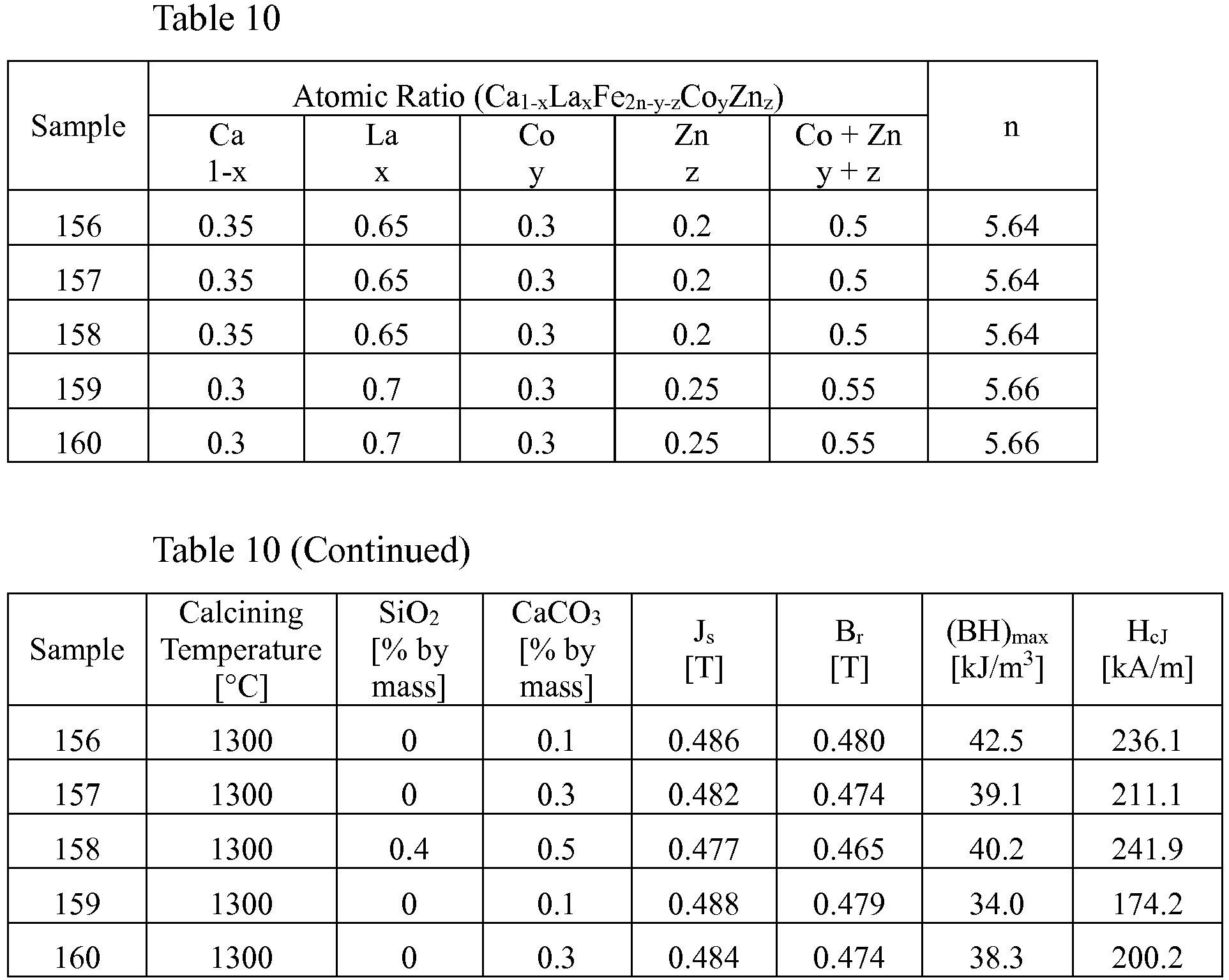
- As shown in Table 10, the sintered ferrite magnets of Experiments of the present invention exhibited as high Br as 0.480 T at maximum.
- The present invention can provide sintered ferrite magnets having high Br with little decrease in HcJ, which can be used suitably for motors for home electric appliances, etc.
Claims (7)
- A sintered ferrite magnet represented by the general formula of Ca1-xLaxFe2n-y-zCoyZnz expressing the atomic ratios of metal elements of Ca, La, Fe, Co and Zn, wherein x, y, z, and n [2n is a molar ratio represented by 2n = (Fe + Co + Zn)/(Ca + La)] meet0.4 <x< 0.75,0.15 ≤ y < 0.4,0.11 ≤ z < 0.4,0.26 ≤ (y + z) < 0.65, and3 ≤ n ≤ 6.
- The sintered ferrite magnet according to claim 1, wherein said x and y meet 0.15 ≤ y ≤ 0.35, and 0.15 ≤ z ≤ 0.35.
- The sintered ferrite magnet according to claim 1 or 2, wherein said x meets 0.475 ≤ x ≤ 0.7.
- The sintered ferrite magnet according to any one of claims 1-3, wherein said y and z meet 0.26 ≤ (y + z) ≤ 0.6.
- The sintered ferrite magnet according to any one of claims 1-4, wherein 1.8% or less by mass of SiO2 is contained.
- The sintered ferrite magnet according to any one of claims 1-5, wherein part of La is substituted by at least one of rare earth elements excluding La in the above general formula.
- The sintered ferrite magnet according to claim 6, wherein 50% or less by mol of La is substituted by at least one of rare earth elements excluding La in the above general formula.
Applications Claiming Priority (3)
| Application Number | Priority Date | Filing Date | Title |
|---|---|---|---|
| JP2017102245 | 2017-05-24 | ||
| JP2018052106 | 2018-03-20 | ||
| PCT/JP2018/019104 WO2018216594A1 (en) | 2017-05-24 | 2018-05-17 | Ferrite sintered magnet |
Publications (2)
| Publication Number | Publication Date |
|---|---|
| EP3633697A1 true EP3633697A1 (en) | 2020-04-08 |
| EP3633697A4 EP3633697A4 (en) | 2021-03-10 |
Family
ID=64396726
Family Applications (1)
| Application Number | Title | Priority Date | Filing Date |
|---|---|---|---|
| EP18806853.0A Ceased EP3633697A4 (en) | 2017-05-24 | 2018-05-17 | SRIED FERRITE MAGNET |
Country Status (6)
| Country | Link |
|---|---|
| US (1) | US11289250B2 (en) |
| EP (1) | EP3633697A4 (en) |
| JP (1) | JP6414372B1 (en) |
| KR (1) | KR102166901B1 (en) |
| CN (1) | CN110663094A (en) |
| WO (1) | WO2018216594A1 (en) |
Cited By (5)
| Publication number | Priority date | Publication date | Assignee | Title |
|---|---|---|---|---|
| US11521769B2 (en) | 2019-03-27 | 2022-12-06 | Tdk Corporation | Ferrite sintered magnet and rotary electrical machine comprising the same |
| US11532413B2 (en) | 2019-03-27 | 2022-12-20 | Tdk Corporation | Ferrite sintered magnet and rotary electrical machine comprising the same |
| US11557412B2 (en) | 2019-03-27 | 2023-01-17 | Tdk Corporation | Ferrite sintered magnet and rotating electric machine comprising the same |
| US11610705B2 (en) | 2019-03-27 | 2023-03-21 | Tdk Corporation | Ferrite sintered magnet and rotating electric machine comprising the same |
| US11626222B2 (en) | 2019-10-18 | 2023-04-11 | Tdk Corporation | Ferrite sintered magnet and rotary electrical machine comprising the same |
Families Citing this family (6)
| Publication number | Priority date | Publication date | Assignee | Title |
|---|---|---|---|---|
| US11551711B2 (en) * | 2019-02-15 | 2023-01-10 | Sony Group Corporation | Cobalt ferrite magnetic powder, method of producing the same, and magnetic recording medium |
| JP7468009B2 (en) * | 2019-03-20 | 2024-04-16 | 株式会社プロテリアル | Ferrite calcined body, sintered ferrite magnet and method for producing same |
| US12243668B2 (en) * | 2019-03-29 | 2025-03-04 | Tdk Corporation | Ferrite sintered magnet, ferrite particles, bonded magnet, and rotating electrical machine |
| CN117727518A (en) * | 2020-03-24 | 2024-03-19 | 株式会社博迈立铖 | Calcined ferrite and sintered ferrite magnet and method for producing the same |
| JP7468045B2 (en) * | 2020-03-24 | 2024-04-16 | 株式会社プロテリアル | Ferrite calcined powder, sintered ferrite magnet and method for producing same |
| JP7347296B2 (en) * | 2020-03-30 | 2023-09-20 | Tdk株式会社 | Ferrite sintered magnets and rotating electrical machines |
Family Cites Families (13)
| Publication number | Priority date | Publication date | Assignee | Title |
|---|---|---|---|---|
| JP3163279B2 (en) | 1997-02-25 | 2001-05-08 | ティーディーケイ株式会社 | Sintered magnet and motor |
| US6139766A (en) | 1997-02-25 | 2000-10-31 | Tdk Corporation | Oxide magnetic material, ferrite particle, sintered magnet, bonded magnet, magnetic recording medium and motor |
| DE69826631T3 (en) * | 1997-09-19 | 2014-10-23 | Tdk Corp. | MAGNETIC POWDER, SINTER MAGNET, ITS MANUFACTURING METHOD, COMPOUND MAGNET, ENGINE, AND MAGNETIC RECORDING MEDIUM |
| US7758767B2 (en) | 2004-09-10 | 2010-07-20 | Neomax Co., Ltd. | Oxide magnetic material and sintered magnet |
| DE602006021780D1 (en) | 2005-11-25 | 2011-06-16 | Hitachi Metals Ltd | MAGNETIC MATERIAL ON OXID BASE, MANUFACTURING METHOD, SINTERED FERRITE MAGNET AND MANUFACTURING METHOD THEREFOR |
| JP4640432B2 (en) * | 2008-03-31 | 2011-03-02 | Tdk株式会社 | Ferrite sintered magnet |
| JP5521287B2 (en) | 2008-06-18 | 2014-06-11 | 日立金属株式会社 | Ferrite particles for magnetic recording media |
| JP5804370B2 (en) | 2010-09-14 | 2015-11-04 | 日立金属株式会社 | Method for producing oxide magnetic material |
| US9401235B2 (en) | 2010-12-28 | 2016-07-26 | Hitachi Metals, Ltd. | Sintered ferrite magnet and its production method |
| JP2012209295A (en) * | 2011-03-29 | 2012-10-25 | Hitachi Metals Ltd | Ferrite sintered magnet |
| EP2881956B1 (en) | 2012-07-31 | 2017-07-05 | Hitachi Metals, Ltd. | Sintered ferrite magnet and its production method |
| JP6860285B2 (en) * | 2015-09-28 | 2021-04-14 | 日立金属株式会社 | Manufacturing method of Ca-La-Co-based ferrite sintered magnet and Ca-La-Co-based ferrite sintered magnet |
| JP6598660B2 (en) | 2015-12-01 | 2019-10-30 | キヤノン株式会社 | Image processing apparatus and image processing method |
-
2018
- 2018-05-17 EP EP18806853.0A patent/EP3633697A4/en not_active Ceased
- 2018-05-17 KR KR1020197034393A patent/KR102166901B1/en active Active
- 2018-05-17 JP JP2018540875A patent/JP6414372B1/en active Active
- 2018-05-17 CN CN201880033415.5A patent/CN110663094A/en active Pending
- 2018-05-17 WO PCT/JP2018/019104 patent/WO2018216594A1/en not_active Ceased
- 2018-05-17 US US16/611,517 patent/US11289250B2/en active Active
Cited By (5)
| Publication number | Priority date | Publication date | Assignee | Title |
|---|---|---|---|---|
| US11521769B2 (en) | 2019-03-27 | 2022-12-06 | Tdk Corporation | Ferrite sintered magnet and rotary electrical machine comprising the same |
| US11532413B2 (en) | 2019-03-27 | 2022-12-20 | Tdk Corporation | Ferrite sintered magnet and rotary electrical machine comprising the same |
| US11557412B2 (en) | 2019-03-27 | 2023-01-17 | Tdk Corporation | Ferrite sintered magnet and rotating electric machine comprising the same |
| US11610705B2 (en) | 2019-03-27 | 2023-03-21 | Tdk Corporation | Ferrite sintered magnet and rotating electric machine comprising the same |
| US11626222B2 (en) | 2019-10-18 | 2023-04-11 | Tdk Corporation | Ferrite sintered magnet and rotary electrical machine comprising the same |
Also Published As
| Publication number | Publication date |
|---|---|
| CN110663094A (en) | 2020-01-07 |
| US11289250B2 (en) | 2022-03-29 |
| WO2018216594A1 (en) | 2018-11-29 |
| EP3633697A4 (en) | 2021-03-10 |
| US20200211743A1 (en) | 2020-07-02 |
| KR102166901B1 (en) | 2020-10-16 |
| KR20200010264A (en) | 2020-01-30 |
| JP6414372B1 (en) | 2018-10-31 |
| JPWO2018216594A1 (en) | 2019-06-27 |
Similar Documents
| Publication | Publication Date | Title |
|---|---|---|
| US11289250B2 (en) | Sintered ferrite magnet | |
| EP2660830B1 (en) | Ferrite sintered magnet and method for producing same | |
| KR101836964B1 (en) | Ferrite calcined body, method for producing ferrite sintered magnet, and ferrite sintered magnet | |
| KR101836965B1 (en) | Ferrite sintered magnet and method for producing same | |
| JP2012209295A (en) | Ferrite sintered magnet | |
| EP3885327B1 (en) | Calcined ferrite, and sintered ferrite magnet and its production method | |
| KR102281215B1 (en) | Ferrite plastic body, ferrite sintered magnet and manufacturing method thereof | |
| JP7238917B2 (en) | Method for producing calcined ferrite powder and sintered ferrite magnet | |
| JP2020155609A (en) | Method for manufacturing ferrite sintered magnet | |
| KR20220040998A (en) | Ferrite calcined body, manufacturing method of ferrite sintered magnet | |
| KR102431513B1 (en) | Calcined ferrite, and sintered ferrite magnet and its production method | |
| JP7639733B2 (en) | Method for producing ferrite calcined body and sintered ferrite magnet | |
| JP7508967B2 (en) | Ferrite calcined body, sintered ferrite magnet and method for producing same | |
| JP7468045B2 (en) | Ferrite calcined powder, sintered ferrite magnet and method for producing same | |
| JP2024126609A (en) | Ferrite calcined body, sintered ferrite magnet, and method for producing sintered ferrite magnet | |
| JP2024122839A (en) | Ferrite calcined body, sintered ferrite magnet, and method for producing sintered ferrite magnet | |
| JP2025033920A (en) | Sintered ferrite magnet and method for producing the same | |
| JP2024131943A (en) | Ferrite calcined body and its manufacturing method |
Legal Events
| Date | Code | Title | Description |
|---|---|---|---|
| STAA | Information on the status of an ep patent application or granted ep patent |
Free format text: STATUS: THE INTERNATIONAL PUBLICATION HAS BEEN MADE |
|
| PUAI | Public reference made under article 153(3) epc to a published international application that has entered the european phase |
Free format text: ORIGINAL CODE: 0009012 |
|
| STAA | Information on the status of an ep patent application or granted ep patent |
Free format text: STATUS: REQUEST FOR EXAMINATION WAS MADE |
|
| 17P | Request for examination filed |
Effective date: 20191125 |
|
| AK | Designated contracting states |
Kind code of ref document: A1 Designated state(s): AL AT BE BG CH CY CZ DE DK EE ES FI FR GB GR HR HU IE IS IT LI LT LU LV MC MK MT NL NO PL PT RO RS SE SI SK SM TR |
|
| AX | Request for extension of the european patent |
Extension state: BA ME |
|
| DAV | Request for validation of the european patent (deleted) | ||
| DAX | Request for extension of the european patent (deleted) | ||
| A4 | Supplementary search report drawn up and despatched |
Effective date: 20210209 |
|
| RIC1 | Information provided on ipc code assigned before grant |
Ipc: C01G 49/00 20060101ALI20210203BHEP Ipc: H01F 1/10 20060101AFI20210203BHEP |
|
| STAA | Information on the status of an ep patent application or granted ep patent |
Free format text: STATUS: EXAMINATION IS IN PROGRESS |
|
| 17Q | First examination report despatched |
Effective date: 20211216 |
|
| RAP3 | Party data changed (applicant data changed or rights of an application transferred) |
Owner name: PROTERIAL, LTD. |
|
| REG | Reference to a national code |
Ref country code: DE Ref legal event code: R003 |
|
| STAA | Information on the status of an ep patent application or granted ep patent |
Free format text: STATUS: THE APPLICATION HAS BEEN REFUSED |
|
| 18R | Application refused |
Effective date: 20230901 |