EP3633666A1 - Brightness adjustment system - Google Patents
Brightness adjustment system Download PDFInfo
- Publication number
- EP3633666A1 EP3633666A1 EP17911037.4A EP17911037A EP3633666A1 EP 3633666 A1 EP3633666 A1 EP 3633666A1 EP 17911037 A EP17911037 A EP 17911037A EP 3633666 A1 EP3633666 A1 EP 3633666A1
- Authority
- EP
- European Patent Office
- Prior art keywords
- block
- luminance
- image data
- pixel
- original image
- Prior art date
- Legal status (The legal status is an assumption and is not a legal conclusion. Google has not performed a legal analysis and makes no representation as to the accuracy of the status listed.)
- Granted
Links
Images


Classifications
-
- G—PHYSICS
- G09—EDUCATION; CRYPTOGRAPHY; DISPLAY; ADVERTISING; SEALS
- G09G—ARRANGEMENTS OR CIRCUITS FOR CONTROL OF INDICATING DEVICES USING STATIC MEANS TO PRESENT VARIABLE INFORMATION
- G09G3/00—Control arrangements or circuits, of interest only in connection with visual indicators other than cathode-ray tubes
- G09G3/20—Control arrangements or circuits, of interest only in connection with visual indicators other than cathode-ray tubes for presentation of an assembly of a number of characters, e.g. a page, by composing the assembly by combination of individual elements arranged in a matrix no fixed position being assigned to or needed to be assigned to the individual characters or partial characters
- G09G3/2003—Display of colours
-
- G—PHYSICS
- G06—COMPUTING OR CALCULATING; COUNTING
- G06T—IMAGE DATA PROCESSING OR GENERATION, IN GENERAL
- G06T5/00—Image enhancement or restoration
- G06T5/90—Dynamic range modification of images or parts thereof
- G06T5/94—Dynamic range modification of images or parts thereof based on local image properties, e.g. for local contrast enhancement
-
- G—PHYSICS
- G06—COMPUTING OR CALCULATING; COUNTING
- G06T—IMAGE DATA PROCESSING OR GENERATION, IN GENERAL
- G06T5/00—Image enhancement or restoration
- G06T5/70—Denoising; Smoothing
-
- G—PHYSICS
- G06—COMPUTING OR CALCULATING; COUNTING
- G06T—IMAGE DATA PROCESSING OR GENERATION, IN GENERAL
- G06T7/00—Image analysis
- G06T7/10—Segmentation; Edge detection
- G06T7/13—Edge detection
-
- G—PHYSICS
- G06—COMPUTING OR CALCULATING; COUNTING
- G06T—IMAGE DATA PROCESSING OR GENERATION, IN GENERAL
- G06T7/00—Image analysis
- G06T7/90—Determination of colour characteristics
-
- G—PHYSICS
- G09—EDUCATION; CRYPTOGRAPHY; DISPLAY; ADVERTISING; SEALS
- G09G—ARRANGEMENTS OR CIRCUITS FOR CONTROL OF INDICATING DEVICES USING STATIC MEANS TO PRESENT VARIABLE INFORMATION
- G09G3/00—Control arrangements or circuits, of interest only in connection with visual indicators other than cathode-ray tubes
- G09G3/20—Control arrangements or circuits, of interest only in connection with visual indicators other than cathode-ray tubes for presentation of an assembly of a number of characters, e.g. a page, by composing the assembly by combination of individual elements arranged in a matrix no fixed position being assigned to or needed to be assigned to the individual characters or partial characters
- G09G3/22—Control arrangements or circuits, of interest only in connection with visual indicators other than cathode-ray tubes for presentation of an assembly of a number of characters, e.g. a page, by composing the assembly by combination of individual elements arranged in a matrix no fixed position being assigned to or needed to be assigned to the individual characters or partial characters using controlled light sources
- G09G3/30—Control arrangements or circuits, of interest only in connection with visual indicators other than cathode-ray tubes for presentation of an assembly of a number of characters, e.g. a page, by composing the assembly by combination of individual elements arranged in a matrix no fixed position being assigned to or needed to be assigned to the individual characters or partial characters using controlled light sources using electroluminescent panels
- G09G3/32—Control arrangements or circuits, of interest only in connection with visual indicators other than cathode-ray tubes for presentation of an assembly of a number of characters, e.g. a page, by composing the assembly by combination of individual elements arranged in a matrix no fixed position being assigned to or needed to be assigned to the individual characters or partial characters using controlled light sources using electroluminescent panels semiconductive, e.g. using light-emitting diodes [LED]
- G09G3/3208—Control arrangements or circuits, of interest only in connection with visual indicators other than cathode-ray tubes for presentation of an assembly of a number of characters, e.g. a page, by composing the assembly by combination of individual elements arranged in a matrix no fixed position being assigned to or needed to be assigned to the individual characters or partial characters using controlled light sources using electroluminescent panels semiconductive, e.g. using light-emitting diodes [LED] organic, e.g. using organic light-emitting diodes [OLED]
-
- G—PHYSICS
- G06—COMPUTING OR CALCULATING; COUNTING
- G06T—IMAGE DATA PROCESSING OR GENERATION, IN GENERAL
- G06T2207/00—Indexing scheme for image analysis or image enhancement
- G06T2207/20—Special algorithmic details
- G06T2207/20021—Dividing image into blocks, subimages or windows
-
- G—PHYSICS
- G06—COMPUTING OR CALCULATING; COUNTING
- G06T—IMAGE DATA PROCESSING OR GENERATION, IN GENERAL
- G06T2207/00—Indexing scheme for image analysis or image enhancement
- G06T2207/20—Special algorithmic details
- G06T2207/20172—Image enhancement details
- G06T2207/20192—Edge enhancement; Edge preservation
-
- G—PHYSICS
- G09—EDUCATION; CRYPTOGRAPHY; DISPLAY; ADVERTISING; SEALS
- G09G—ARRANGEMENTS OR CIRCUITS FOR CONTROL OF INDICATING DEVICES USING STATIC MEANS TO PRESENT VARIABLE INFORMATION
- G09G2320/00—Control of display operating conditions
- G09G2320/02—Improving the quality of display appearance
- G09G2320/0238—Improving the black level
-
- G—PHYSICS
- G09—EDUCATION; CRYPTOGRAPHY; DISPLAY; ADVERTISING; SEALS
- G09G—ARRANGEMENTS OR CIRCUITS FOR CONTROL OF INDICATING DEVICES USING STATIC MEANS TO PRESENT VARIABLE INFORMATION
- G09G2320/00—Control of display operating conditions
- G09G2320/04—Maintaining the quality of display appearance
- G09G2320/043—Preventing or counteracting the effects of ageing
-
- G—PHYSICS
- G09—EDUCATION; CRYPTOGRAPHY; DISPLAY; ADVERTISING; SEALS
- G09G—ARRANGEMENTS OR CIRCUITS FOR CONTROL OF INDICATING DEVICES USING STATIC MEANS TO PRESENT VARIABLE INFORMATION
- G09G2320/00—Control of display operating conditions
- G09G2320/06—Adjustment of display parameters
- G09G2320/0626—Adjustment of display parameters for control of overall brightness
-
- G—PHYSICS
- G09—EDUCATION; CRYPTOGRAPHY; DISPLAY; ADVERTISING; SEALS
- G09G—ARRANGEMENTS OR CIRCUITS FOR CONTROL OF INDICATING DEVICES USING STATIC MEANS TO PRESENT VARIABLE INFORMATION
- G09G2320/00—Control of display operating conditions
- G09G2320/06—Adjustment of display parameters
- G09G2320/0626—Adjustment of display parameters for control of overall brightness
- G09G2320/0646—Modulation of illumination source brightness and image signal correlated to each other
-
- G—PHYSICS
- G09—EDUCATION; CRYPTOGRAPHY; DISPLAY; ADVERTISING; SEALS
- G09G—ARRANGEMENTS OR CIRCUITS FOR CONTROL OF INDICATING DEVICES USING STATIC MEANS TO PRESENT VARIABLE INFORMATION
- G09G2320/00—Control of display operating conditions
- G09G2320/06—Adjustment of display parameters
- G09G2320/066—Adjustment of display parameters for control of contrast
-
- G—PHYSICS
- G09—EDUCATION; CRYPTOGRAPHY; DISPLAY; ADVERTISING; SEALS
- G09G—ARRANGEMENTS OR CIRCUITS FOR CONTROL OF INDICATING DEVICES USING STATIC MEANS TO PRESENT VARIABLE INFORMATION
- G09G2320/00—Control of display operating conditions
- G09G2320/06—Adjustment of display parameters
- G09G2320/0686—Adjustment of display parameters with two or more screen areas displaying information with different brightness or colours
-
- G—PHYSICS
- G09—EDUCATION; CRYPTOGRAPHY; DISPLAY; ADVERTISING; SEALS
- G09G—ARRANGEMENTS OR CIRCUITS FOR CONTROL OF INDICATING DEVICES USING STATIC MEANS TO PRESENT VARIABLE INFORMATION
- G09G2340/00—Aspects of display data processing
- G09G2340/06—Colour space transformation
-
- G—PHYSICS
- G09—EDUCATION; CRYPTOGRAPHY; DISPLAY; ADVERTISING; SEALS
- G09G—ARRANGEMENTS OR CIRCUITS FOR CONTROL OF INDICATING DEVICES USING STATIC MEANS TO PRESENT VARIABLE INFORMATION
- G09G2360/00—Aspects of the architecture of display systems
- G09G2360/16—Calculation or use of calculated indices related to luminance levels in display data
Definitions
- the present invention relates to the field of display techniques, and in particular to a luminance adjustment system.
- the panel display device provides the advantages of thinness, power-saving, radiation-free, and so on, and is widely applied to various fields.
- the known panel display device mainly comprises liquid crystal display (LCD) and organic light-emitting diode (OLED) display.
- the OLED display provides the advantages of active light-emitting, need for backlight source, low driving voltage, high illumination efficiency, quick response time, high clearness and contrast, near 180° viewing angle, wide operation temperature range, applicable to flexible panel and large-area full-color display, and is regarded as the most promising display technology.
- the OLED display comprises a plurality of pixels arranged in an array, with each pixel comprising: a red sub-pixel (R), a green sub-pixel (G), and a blue sub-pixel (B), and each sub-pixel disposed with an OLED.
- the OLED usually comprises: an anode, a hole injection layer disposed on the anode, a hole transport layer disposed on the hole injection layer, an organic light-emitting layer disposed on the hole transport layer, an electron transport layer disposed on the organic light-emitting layer, an electron injection layer disposed on the electron transport layer, and a cathode disposed on the electron injection layer.
- the operation theory of the OLED display is that the semiconductor material and the organic light-emitting material driven by the electrical field to emit light through carrier injection and combination.
- an approach to address the OLED display ageing and power-consumption problems is: Using average picture level (APL) algorithm to compute the luminance intensity of the display screen. If the screen has too high a luminance intensity, the overall luminance is reduced by adjusting data signal, gamma voltage, or OLED voltage, which achieves reducing OLED power-consumption as well as slowing down OLED ageing.
- APL average picture level
- the object of the present invention is to provide a luminance adjustment system, able to maintain details in darker part of the image, and to adjust the luminance of bright and complex part of the image to a greater extent.
- the present invention provides a luminance adjustment system, comprising:
- the luminance representative value calculation module obtains the luminance representative value of each block as follows:
- the edge information extraction module uses Sobel operator for edge detection to obtain the edge information amount of each block.
- the edge information extraction module obtains the edge information amount of each block as follows:
- each block comprises 3x3 pixels
- the adjustment gain calculation module calculates the luminance adjustment coefficient of each block as follows:
- the gain smooth processing module performs calibration on the luminance adjustment coefficient of each block as follows:
- the data modulation module obtains the modulated image data of each block as follows:
- the present invention also provides a luminance adjustment system, comprising:
- the present invention provides a luminance adjustment system, by dividing an image into blocks, and combined with the luminance representative value and the amount of edge information amount indicating the complexity of the image of each block, to perform an individual luminance adjustment on each block, so that a more accurate adjustment can be achieved.
- the present invention can maintain details in darker part of the image, and to adjust the luminance of bright and complex part of the image to a greater extent.
- the present invention provides a luminance adjustment system, comprising: a block division module 1, a luminance representative value calculation module 2 electrically connected to the block division module 1, an edge information extraction module 3 electrically connected to the block division module 1, an adjustment gain calculation module 4 electrically connected to the luminance representative value calculation module 2 and the edge information extraction module 3, a gain smooth processing module 5 electrically connected to the adjustment gain calculation module 4, and a data modulation module 6 electrically connected to the gain smooth processing module 5.
- the block division module 1 is for receiving original image data and dividing image into MxN blocks D along X-direction and Y-direction; wherein, M and N both are positive integers; each block D comprises a plurality of pixels P arranged in an array, and the original image data of each pixel P comprises: red original image data R, green original image data G, and blue original image data B.
- the luminance representative value calculation module 2 is for obtaining a luminance representative value for each block D.
- the luminance representative value calculation module 2 obtains the luminance representative value of each block D as follows: First, obtaining a luminance feature value TBP of each pixel P in a block D.
- the edge information extraction module 3 is for analyzing the original image data of each block D to obtain an edge information amount of each block D.
- the edge information extraction module 3 uses Sobel operator for edge detection. Take each block comprising 3x3 pixels P as example.
- A is an original image of a block D
- the image of X-direction edge detection is: ⁇ 1 0 + 1 ⁇ 2 0 + 2 ⁇ 1 0 + 1 ⁇ A
- the image of Y-direction edge detection is: + 1 + 2 + 1 0 0 0 ⁇ 1 ⁇ 2 ⁇ 1 ⁇ A
- the edge information extraction module 3 obtains the edge information amount of each block D as follows:
- the edge information amount indicates the image complexity. The higher the edge information amount is, the more complex the image is.
- the adjustment gain calculation module 4 is for calculating a luminance adjustment coefficient of each block D based on the luminance representative value and the edge information amount of each block D.
- the luminance representative value APL is 255.
- the target luminance for grayscale 255 decreases as the grayscale corresponding to the luminance representative value increases. That is, the higher the grayscale corresponding to the luminance representative value APL is, the lower the target luminance for grayscale 255 is.
- the edge luminance adjustment coefficient K edge decreases as the edge information amount increases. That is, the larger the edge information amount is, the image is more complex, the lower the luminance is adjusted to so as to match the property that human eyes are more sensitive to complex image at lower luminance. Therefore, the luminance of complex image block D is adjusted to a greater extent.
- the gain smooth processing module 5 is for performing calibration the luminance adjustment coefficient of each block D to obtain a luminance adjustment calibration value of each block D so as to performing smooth processing on each pixel P in each block D to prevent luminance at borders between blocks D from mutating.
- the gain smooth processing module 5 performs calibration on the luminance adjustment coefficient of each block D as follows:
- the data modulation module electrically 6 is for performing modulation on the original image data based on the luminance adjustment calibration value of each block D to obtain a modulated image data of each block D so as to perform individual luminance modulation on each block D.
- the data modulation module 6 obtains the modulated image data of each block as follows:
- the luminance adjustment system of the present invention can, by dividing an image into blocks, and combining with the luminance representative value and the amount of edge information amount indicating the complexity of the image of each block, perform an individual luminance adjustment on each block, so that a more accurate adjustment can be achieved.
- the present invention can maintain details in darker part of the image, and to adjust the luminance of bright and complex part of the image to a greater extent.
- the present invention provides a luminance adjustment system, by dividing an image into blocks, and combined with the luminance representative value and the amount of edge information amount indicating the complexity of the image of each block, to perform an individual luminance adjustment on each block, so that a more accurate adjustment can be achieved.
- the present invention can maintain details in darker part of the image, and to adjust the luminance of bright and complex part of the image to a greater extent.
Landscapes
- Engineering & Computer Science (AREA)
- Physics & Mathematics (AREA)
- General Physics & Mathematics (AREA)
- Theoretical Computer Science (AREA)
- Computer Hardware Design (AREA)
- Computer Vision & Pattern Recognition (AREA)
- Image Processing (AREA)
- Control Of El Displays (AREA)
- Electroluminescent Light Sources (AREA)
- Control Of Indicators Other Than Cathode Ray Tubes (AREA)
Abstract
Description
- The present invention relates to the field of display techniques, and in particular to a luminance adjustment system.
- The panel display device provides the advantages of thinness, power-saving, radiation-free, and so on, and is widely applied to various fields. The known panel display device mainly comprises liquid crystal display (LCD) and organic light-emitting diode (OLED) display.
- The OLED display provides the advantages of active light-emitting, need for backlight source, low driving voltage, high illumination efficiency, quick response time, high clearness and contrast, near 180° viewing angle, wide operation temperature range, applicable to flexible panel and large-area full-color display, and is regarded as the most promising display technology.
- The OLED display comprises a plurality of pixels arranged in an array, with each pixel comprising: a red sub-pixel (R), a green sub-pixel (G), and a blue sub-pixel (B), and each sub-pixel disposed with an OLED. The OLED usually comprises: an anode, a hole injection layer disposed on the anode, a hole transport layer disposed on the hole injection layer, an organic light-emitting layer disposed on the hole transport layer, an electron transport layer disposed on the organic light-emitting layer, an electron injection layer disposed on the electron transport layer, and a cathode disposed on the electron injection layer. The operation theory of the OLED display is that the semiconductor material and the organic light-emitting material driven by the electrical field to emit light through carrier injection and combination.
- At present, the OLED display ageing and power-consumption problems are more prominent. In known technique, an approach to address the OLED display ageing and power-consumption problems is:
Using average picture level (APL) algorithm to compute the luminance intensity of the display screen. If the screen has too high a luminance intensity, the overall luminance is reduced by adjusting data signal, gamma voltage, or OLED voltage, which achieves reducing OLED power-consumption as well as slowing down OLED ageing. - However, the above approach has a shortcoming: for high luminance intensity images with high luminance contrast, the overall image luminance will be reduced to cause the contrast also reduced, as well as losing the details in darker part of the image, resulting in degraded display quality.
- The object of the present invention is to provide a luminance adjustment system, able to maintain details in darker part of the image, and to adjust the luminance of bright and complex part of the image to a greater extent.
- To achieve the above object, the present invention provides a luminance adjustment system, comprising:
- a block division module, for receiving original image data and dividing image into MxN blocks along X-direction and Y-direction; wherein, M and N both positive integers; each block comprising a plurality of pixels arranged in an array, the original image data of each pixel comprising: red original image data, green original image data, and blue original image data;
- a luminance representative value calculation module electrically connected to the block division module, for obtaining a luminance representative value for each block;
- an edge information extraction module electrically connected to the block division module, for analyzing the original image data of each block to obtain an edge information amount of each block;
- an adjustment gain calculation module electrically connected to the luminance representative value calculation module and the edge information extraction module, for calculating a luminance adjustment coefficient of each block based on the luminance representative value and the edge information amount of each block;
- a gain smooth processing module electrically connected to the adjustment gain calculation module, for performing calibration the luminance adjustment coefficient of each block to obtain a luminance adjustment calibration value of each block so as to performing smooth processing on each pixel in each block to prevent luminance at borders between blocks from mutating; and
- a data modulation module electrically connected to the gain smooth processing module, for performing modulation on the original image data based on the luminance adjustment calibration value of each block to obtain a modulated image data of each block so as to perform individual luminance modulation on each block.
- According to a preferred embodiment of the present invention, the luminance representative value calculation module obtains the luminance representative value of each block as follows:
- obtaining a luminance feature value TBP of each pixel in a block; and
- calculating an average of the luminance feature values TBP of all the pixels in the block as the luminance representative value (average picture level, APL) of the block.
- Optionally, the luminance representative value calculation module obtains the luminance feature value TBP of each pixel in the block as follows:
extracting a maximum luminance value corresponding to the red original image data, green original image data, and blue original image data of a pixel as the luminance feature value TBP, i.e.:
- Optionally, the luminance representative value calculation module obtains the luminance feature value TBP of each pixel in the block as follows:
translating the red original image data, green original image data, and blue original image data of a pixel to YCbCr color space, and then calculating the luminance feature value TBP with the following:
- According to a preferred embodiment of the present invention, the edge information extraction module uses Sobel operator for edge detection to obtain the edge information amount of each block.
- According to a preferred embodiment of the present invention, the edge information extraction module obtains the edge information amount of each block as follows:
- first, calculating an X-direction grayscale value Gx and a Y-direction grayscale GY of each pixel in a block:


- wherein f(a,b) is the luminance value of the original image data corresponding to the pixel with X-direction coordinate a and Y-direction coordinate b in the block, SobelX is an X-direction Sobel operator and Sobely is a Y-direction Soble operator;
- then, calculating a gradient G of each pixel in the block:

- then, comparing the gradient G of each pixel in the block with a default threshold; if the gradient G of a pixel being greater than the default threshold, determining the pixel as an edge point;
- finally, summing the number of the pixels determined as edge points in the block as the edge information amount of the block.
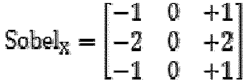
- According to a preferred embodiment of the present invention, each block comprises 3x3 pixels, the X-direction Sobel operator Sobelx and Y-direction Soble operator SobelY are respectively as:


- According to a preferred embodiment of the present invention, the adjustment gain calculation module calculates the luminance adjustment coefficient of each block as follows:
- first, presetting a target luminance for
grayscale 255 at different luminance representative value APL so that the target luminance decreasing as the grayscale corresponding to the luminance representative value increasing, calculating a normal luminance adjustment coefficient K APL of each block as following:
- presetting a relation between the edge information amount and an edge luminance adjustment coefficient Kedge, so that the edge luminance adjustment coefficient Kedge decreasing as the edge information amount increasing, looking for the corresponding edge luminance adjustment coefficient Kedge based on the edge information amount of each block;
- then, calculating the luminance adjustment coefficient K as following:

- According to a preferred embodiment of the present invention, the gain smooth processing module performs calibration on the luminance adjustment coefficient of each block as follows:
- first, selecting a block, calculating a horizontal gain KH of an X-direction adjacent block, and a vertical gain KV of a Y-direction adjacent block for the selected block as following:


- wherein K1 is the luminance adjustment coefficient of the selected block, K2 is the luminance adjustment coefficient of X-direction adjacent block of the selected block, K3 is the luminance adjustment coefficient of Y-direction adjacent block of the selected block, x and y are X-direction and Y-direction coordinates of each pixel with respect to a center pixel of the selected block, X is the horizontal distance between the center pixel of the selected block and the center pixel of the X-direction adjacent block, and Y is the vertical distance between the center pixel of the selected block and the center pixel of the Y-direction adjacent block;
- then, calculating the luminance adjustment calibration value K' of each pixel in the selected block as following:

- According to a preferred embodiment of the present invention, the data modulation module obtains the modulated image data of each block as follows:
- the modulated image data of a block = the luminance adjustment calibration value K' of each pixel in the block × the original image data of the corresponding pixel in the block, i.e.:


- wherein R', G', and B' are modulated red image data, modulated green image data, and modulated blue image data respectively.
- The present invention also provides a luminance adjustment system, comprising:
- a block division module, for receiving original image data and dividing image into MxN blocks along X-direction and Y-direction; wherein, M and N both positive integers; each block comprising a plurality of pixels arranged in an array, the original image data of each pixel comprising: red original image data, green original image data, and blue original image data;
- a luminance representative value calculation module electrically connected to the block division module, for obtaining a luminance representative value for each block;
- an edge information extraction module electrically connected to the block division module, for analyzing the original image data of each block to obtain an edge information amount of each block;
- an adjustment gain calculation module electrically connected to the luminance representative value calculation module and the edge information extraction module, for calculating a luminance adjustment coefficient of each block based on the luminance representative value and the edge information amount of each block;
- a gain smooth processing module electrically connected to the adjustment gain calculation module, for performing calibration the luminance adjustment coefficient of each block to obtain a luminance adjustment calibration value of each block so as to performing smooth processing on each pixel in each block to prevent luminance at borders between blocks from mutating; and
- a data modulation module electrically connected to the gain smooth processing module, for performing modulation on the original image data based on the luminance adjustment calibration value of each block to obtain a modulated image data of each block so as to perform individual luminance modulation on each block;
- wherein the luminance representative value calculation module obtains the luminance representative value of each block as follows:
- obtaining a luminance feature value TBP of each pixel in a block; and
- calculating an average of the luminance feature values TBP of all the pixels in the block as the luminance representative value (average picture level, APL) of the block;
- wherein the edge information extraction module uses Sobel operator for edge detection to obtain the edge information amount of each block;
- wherein the edge information extraction module obtains the edge information amount of each block as follows:
- first, calculating an X-direction grayscale value Gx and a Y-direction grayscale GY of each pixel in a block:


- wherein f(a,b) is the luminance value of the original image data corresponding to the pixel with X-direction coordinate a and Y-direction coordinate b in the block, SobelX is an X-direction Sobel operator and Sobely is a Y-direction Soble operator;
- then, calculating a gradient G of each pixel in the block:

- then, comparing the gradient G of each pixel in the block with a default threshold; if the gradient G of a pixel being greater than the default threshold, determining the pixel as an edge point;
- finally, summing the number of the pixels determined as edge points in the block as the edge information amount of the block;
- wherein each block comprises 3x3 pixels, the X-direction Sobel operator Sobelx and Y-direction Soble operator SobelY are respectively as:


- wherein the adjustment gain calculation module calculates the luminance adjustment coefficient of each block as follows:
- first, presetting a target luminance for
grayscale 255 at different luminance representative value APL so that the target luminance decreasing as the grayscale corresponding to the luminance representative value increasing, calculating a normal luminance adjustment coefficient K APL of each block as following:
- presetting a relation between the edge information amount and an edge luminance adjustment coefficient Kedge, so that the edge luminance adjustment coefficient Kedge decreasing as the edge information amount increasing, looking for the corresponding edge luminance adjustment coefficient Kedge based on the edge information amount of each block;
- then, calculating the luminance adjustment coefficient K as following:

- first, presetting a target luminance for
- first, calculating an X-direction grayscale value Gx and a Y-direction grayscale GY of each pixel in a block:
- Compared to the known techniques, the present invention provides the following advantages. The present invention provides a luminance adjustment system, by dividing an image into blocks, and combined with the luminance representative value and the amount of edge information amount indicating the complexity of the image of each block, to perform an individual luminance adjustment on each block, so that a more accurate adjustment can be achieved. As such, the present invention can maintain details in darker part of the image, and to adjust the luminance of bright and complex part of the image to a greater extent.
- To make the technical solution of the embodiments according to the present invention, a brief description of the drawings that are necessary for the illustration of the embodiments will be given as follows. Apparently, the drawings described below show only example embodiments of the present invention and for those having ordinary skills in the art, other drawings may be easily obtained from these drawings without paying any creative effort. In the drawings:
-
Figure 1 is a schematic view showing a block diagram of the luminance adjustment system according to the present invention; -
Figure 2 is a schematic view showing the block division module of the luminance adjustment system dividing a frame into blocks according to the present invention; -
Figure 3 is a schematic view showing the adjustment gain calculation module of the luminance adjustment system presetting target luminance forgrayscale 255 under different luminance representative value APL according to the present invention; -
Figure 4 is a schematic view showing the adjustment gain calculating module of the luminance adjustment system presetting the relation between edge information amount and edge luminance adjustment coefficient Kedge according to the present invention; -
Figure 5 is a schematic view showing the gain smooth processing module of the luminance adjustment system performing calibration on the luminance adjustment coefficient of each block according to the present invention. - To further explain the technique means and effect of the present invention, the following uses preferred embodiments and drawings for detailed description.
- Referring to
Figure 1 , the present invention provides a luminance adjustment system, comprising: ablock division module 1, a luminance representativevalue calculation module 2 electrically connected to theblock division module 1, an edgeinformation extraction module 3 electrically connected to theblock division module 1, an adjustmentgain calculation module 4 electrically connected to the luminance representativevalue calculation module 2 and the edgeinformation extraction module 3, a gainsmooth processing module 5 electrically connected to the adjustmentgain calculation module 4, and a data modulation module 6 electrically connected to the gainsmooth processing module 5. - Refer to
Figure 1 andFigure 2 . Theblock division module 1 is for receiving original image data and dividing image into MxN blocks D along X-direction and Y-direction; wherein, M and N both are positive integers; each block D comprises a plurality of pixels P arranged in an array, and the original image data of each pixel P comprises: red original image data R, green original image data G, and blue original image data B. - The luminance representative
value calculation module 2 is for obtaining a luminance representative value for each block D. - Specifically, the luminance representative
value calculation module 2 obtains the luminance representative value of each block D as follows:
First, obtaining a luminance feature value TBP of each pixel P in a block D. - Moreover, using one of the following two approaches to obtain the luminance feature value TBP of each pixel P in a block D:
- 1. extracting a maximum luminance value corresponding to the red original image data R, green original image data G, and blue original image data B of a pixel P as the luminance feature value TBP, i.e.:

- 2. translating the red original image data R, green original image data G, and blue original image data B of a pixel P to YCbCr color space, and then calculating the luminance feature value TBP with the following:

- Then, calculating an average of the luminance feature values TBP of all the pixels P in the block D as the luminance representative value (average picture level, APL) of the block.
- The edge
information extraction module 3 is for analyzing the original image data of each block D to obtain an edge information amount of each block D. - Specifically, the edge
information extraction module 3 uses Sobel operator for edge detection. Take each block comprising 3x3 pixels P as example. The X-direction Sobel operator Sobelx and Y-direction Soble operator SobelY are respectively as:

- If A is an original image of a block D, the image of X-direction edge detection is:


- Moreover, the edge
information extraction module 3 obtains the edge information amount of each block D as follows: - First, calculating an X-direction grayscale value Gx and a Y-direction grayscale GY of each pixel P in a block D:


- wherein f(a,b) is the luminance value of the original image data corresponding to the pixel P with X-direction coordinate a and Y-direction coordinate b in the block D; taking each block D comprising 3x3 pixels P as example, then:


- Then, calculating a gradient G of each pixel P in the block D:

- Then, comparing the gradient G of each pixel P in the block D with a default threshold; if the gradient G of a pixel being greater than the default threshold, determining the pixel as an edge point;
Finally, summing the number of the pixels P determined as edge points in the block D as the edge information amount of the block D. The edge information amount indicates the image complexity. The higher the edge information amount is, the more complex the image is. - The adjustment
gain calculation module 4 is for calculating a luminance adjustment coefficient of each block D based on the luminance representative value and the edge information amount of each block D. - Specifically, the adjustment
gain calculation module 4 calculates the luminance adjustment coefficient of each block D as follows:
First, as shown inFigure 3 , presetting a target luminance for 255grayscale 255 at different luminance representative value APL, calculating a normal luminance adjustment coefficient KAPL of each block D as following:
- For example, assuming that the luminance of a block D before adjustment is
grayscale 255, the luminance representative value APL is 255. On the condition that the luminance representative value APL is 255, the target luminance ofgrayscale 255 is Min=64. Then,
- Then, as shown in
Figure 4 , presetting a relation between the edge information amount and an edge luminance adjustment coefficient Kedge, looking for the corresponding edge luminance adjustment coefficient Kedge based on the edge information amount of each block D;
Then, calculating the luminance adjustment coefficient K as following:
- It should be noted that the target luminance for
grayscale 255 decreases as the grayscale corresponding to the luminance representative value increases. That is, the higher the grayscale corresponding to the luminance representative value APL is, the lower the target luminance forgrayscale 255 is. The edge luminance adjustment coefficient Kedge decreases as the edge information amount increases. That is, the larger the edge information amount is, the image is more complex, the lower the luminance is adjusted to so as to match the property that human eyes are more sensitive to complex image at lower luminance. Therefore, the luminance of complex image block D is adjusted to a greater extent. - The gain
smooth processing module 5 is for performing calibration the luminance adjustment coefficient of each block D to obtain a luminance adjustment calibration value of each block D so as to performing smooth processing on each pixel P in each block D to prevent luminance at borders between blocks D from mutating. - Specifically, as shown in
Figure 5 , the gainsmooth processing module 5 performs calibration on the luminance adjustment coefficient of each block D as follows: - First, selecting a block D, calculating a horizontal gain KH of an X-direction adjacent block D, and a vertical gain KV of a Y-direction adjacent block D for the selected block D as following:


- wherein K1 is the luminance adjustment coefficient of the selected block D, K2 is the luminance adjustment coefficient of X-direction adjacent block D of the selected block D, K3 is the luminance adjustment coefficient of Y-direction adjacent block D of the selected block D, x and y are X-direction and Y-direction coordinates of each pixel P with respect to a center pixel P of the selected block D, X is the horizontal distance between the center pixel P of the selected block D and the center pixel P of the X-direction adjacent block D, and Y is the vertical distance between the center pixel P of the selected block D and the center pixel P of the Y-direction adjacent block D;
- Then, calculating the luminance adjustment calibration value K' of each pixel P in the selected block D as following:

- The data modulation module electrically 6 is for performing modulation on the original image data based on the luminance adjustment calibration value of each block D to obtain a modulated image data of each block D so as to perform individual luminance modulation on each block D.
- Specifically, the data modulation module 6 obtains the modulated image data of each block as follows:
- the modulated image data of a block D = the luminance adjustment calibration value K' of each pixel P in the block D × the original image data of the corresponding pixel P in the block D, i.e.:


- wherein R', G', and B' are modulated red image data, modulated green image data, and modulated blue image data respectively.
- Therefore, the luminance adjustment system of the present invention can, by dividing an image into blocks, and combining with the luminance representative value and the amount of edge information amount indicating the complexity of the image of each block, perform an individual luminance adjustment on each block, so that a more accurate adjustment can be achieved. As such, the present invention can maintain details in darker part of the image, and to adjust the luminance of bright and complex part of the image to a greater extent.
- In summary, the present invention provides a luminance adjustment system, by dividing an image into blocks, and combined with the luminance representative value and the amount of edge information amount indicating the complexity of the image of each block, to perform an individual luminance adjustment on each block, so that a more accurate adjustment can be achieved. As such, the present invention can maintain details in darker part of the image, and to adjust the luminance of bright and complex part of the image to a greater extent.
- It should be noted that in the present disclosure the terms, such as, first, second are only for distinguishing an entity or operation from another entity or operation, and does not imply any specific relation or order between the entities or operations. Also, the terms "comprises", "include", and other similar variations, do not exclude the inclusion of other non-listed elements. Without further restrictions, the expression "comprises a..." does not exclude other identical elements from presence besides the listed elements.
- Embodiments of the present invention have been described, but not intending to impose any unduly constraint to the appended claims. Any modification of equivalent structure or equivalent process made according to the disclosure and drawings of the present invention, or any application thereof, directly or indirectly, to other related fields of technique, is considered encompassed in the scope of protection defined by the clams of the present invention.
Claims (15)
- A luminance adjustment system, comprising:a block division module, for receiving original image data and dividing image into MxN blocks along X-direction and Y-direction; wherein, M and N both positive integers; each block comprising a plurality of pixels arranged in an array, the original image data of each pixel comprising: red original image data, green original image data, and blue original image data;a luminance representative value calculation module electrically connected to the block division module, for obtaining a luminance representative value for each block;an edge information extraction module electrically connected to the block division module, for analyzing the original image data of each block to obtain an edge information amount of each block;an adjustment gain calculation module electrically connected to the luminance representative value calculation module and the edge information extraction module, for calculating a luminance adjustment coefficient of each block based on the luminance representative value and the edge information amount of each block;a gain smooth processing module electrically connected to the adjustment gain calculation module, for performing calibration the luminance adjustment coefficient of each block to obtain a luminance adjustment calibration value of each block so as to performing smooth processing on each pixel in each block to prevent luminance at borders between blocks from mutating; anda data modulation module electrically connected to the gain smooth processing module, for performing modulation on the original image data based on the luminance adjustment calibration value of each block to obtain a modulated image data of each block so as to perform individual luminance modulation on each block.
- The luminance adjustment system as claimed in Claim 1, wherein the luminance representative value calculation module obtains the luminance representative value of each block as follows:obtaining a luminance feature value TBP of each pixel in a block; andcalculating an average of the luminance feature values TBP of all the pixels in the block as the luminance representative value (average picture level, APL) of the block.
- The luminance adjustment system as claimed in Claim 2, wherein the luminance representative value calculation module obtains the luminance feature value TBP of each pixel in the block as follows:
extracting a maximum luminance value corresponding to the red original image data, green original image data, and blue original image data of a pixel as the luminance feature value TBP, i.e.:
- The luminance adjustment system as claimed in Claim 2, wherein the luminance representative value calculation module obtains the luminance feature value TBP of each pixel in the block as follows:
translating the red original image data, green original image data, and blue original image data of a pixel to YCbCr color space, and then calculating the luminance feature value TBP with the following:
- The luminance adjustment system as claimed in Claim 1, wherein the edge information extraction module uses Sobel operator for edge detection to obtain the edge information amount of each block.
- The luminance adjustment system as claimed in Claim 5, wherein the edge information extraction module obtains the edge information amount of each block as follows:calculating an X-direction grayscale value Gx and a Y-direction grayscale GY of each pixel in a block:

 wherein f(a,b) is the luminance value of the original image data corresponding to the pixel with X-direction coordinate a and Y-direction coordinate b in the block, Sobelx is an X-direction Sobel operator and SobelY is a Y-direction Soble operator;calculating a gradient G of each pixel in the block:
 comparing the gradient G of each pixel in the block with a default threshold; if the gradient G of a pixel being greater than the default threshold, determining the pixel as an edge point; andsumming the number of the pixels determined as edge points in the block as the edge information amount of the block.
 - The luminance adjustment system as claimed in Claim 6, wherein each block comprises 3x3 pixels, the X-direction Sobel operator Sobelx and Y-direction Soble operator SobelY are respectively as:

- The luminance adjustment system as claimed in Claim 6, wherein the adjustment gain calculation module calculates the luminance adjustment coefficient of each block as follows:presetting a target luminance for grayscale 255 at different luminance representative value APL so that the target luminance decreasing as the grayscale corresponding to the luminance representative value increasing, calculating a normal luminance adjustment coefficient K APL of each block as following:
 presetting a relation between the edge information amount and an edge luminance adjustment coefficient Kedge, so that the edge luminance adjustment coefficient Kedge decreasing as the edge information amount increasing, looking for the corresponding edge luminance adjustment coefficient Kedge based on the edge information amount of each block;calculating the luminance adjustment coefficient K as following:
- The luminance adjustment system as claimed in Claim 8, wherein the gain smooth processing module performs calibration on the luminance adjustment coefficient of each block as follows:selecting a block, calculating a horizontal gain KH of an X-direction adjacent block, and a vertical gain KV of a Y-direction adjacent block for the selected block as following:

 wherein K1 is the luminance adjustment coefficient of the selected block, K2 is the luminance adjustment coefficient of X-direction adjacent block of the selected block, K3 is the luminance adjustment coefficient of Y-direction adjacent block of the selected block, x and y are X-direction and Y-direction coordinates of each pixel with respect to a center pixel of the selected block, X is the horizontal distance between the center pixel of the selected block and the center pixel of the X-direction adjacent block, and Y is the vertical distance between the center pixel of the selected block and the center pixel of the Y-direction adjacent block;then, calculating the luminance adjustment calibration value K' of each pixel in the selected block as following:
- The luminance adjustment system as claimed in Claim 9, wherein the data modulation module obtains the modulated image data of each block as follows:


- A luminance adjustment system, comprising:a block division module, for receiving original image data and dividing image into MxN blocks along X-direction and Y-direction; wherein, M and N both positive integers; each block comprising a plurality of pixels arranged in an array, the original image data of each pixel comprising: red original image data, green original image data, and blue original image data;a luminance representative value calculation module electrically connected to the block division module, for obtaining a luminance representative value for each block;an edge information extraction module electrically connected to the block division module, for analyzing the original image data of each block to obtain an edge information amount of each block;an adjustment gain calculation module electrically connected to the luminance representative value calculation module and the edge information extraction module, for calculating a luminance adjustment coefficient of each block based on the luminance representative value and the edge information amount of each block;a gain smooth processing module electrically connected to the adjustment gain calculation module, for performing calibration the luminance adjustment coefficient of each block to obtain a luminance adjustment calibration value of each block so as to performing smooth processing on each pixel in each block to prevent luminance at borders between blocks from mutating; anda data modulation module electrically connected to the gain smooth processing module, for performing modulation on the original image data based on the luminance adjustment calibration value of each block to obtain a modulated image data of each block so as to perform individual luminance modulation on each block;wherein the luminance representative value calculation module obtains the luminance representative value of each block as follows:obtaining a luminance feature value TBP of each pixel in a block; andcalculating an average of the luminance feature values TBP of all the pixels in the block as the luminance representative value (average picture level, APL) of the block;wherein the edge information extraction module uses Sobel operator for edge detection to obtain the edge information amount of each bloc;wherein the edge information extraction module obtains the edge information amount of each block as follows:calculating an X-direction grayscale value Gx and a Y-direction grayscale GY of each pixel in a block:

 wherein f(a,b) is the luminance value of the original image data corresponding to the pixel with X-direction coordinate a and Y-direction coordinate b in the block, Sobelx is an X-direction Sobel operator and SobelY is a Y-direction Soble operator;calculating a gradient G of each pixel in the block:
 comparing the gradient G of each pixel in the block with a default threshold; if the gradient G of a pixel being greater than the default threshold, determining the pixel as an edge point; andsumming the number of the pixels determined as edge points in the block as the edge information amount of the block;wherein each block comprises 3x3 pixels, the X-direction Sobel operator Sobelx and Y-direction Soble operator SobelY are respectively as:
 wherein the adjustment gain calculation module calculates the luminance adjustment coefficient of each block as follows:presetting a target luminance for grayscale 255 at different luminance representative value APL so that the target luminance decreasing as the grayscale corresponding to the luminance representative value increasing, calculating a normal luminance adjustment coefficient K APL of each block as following:
 presetting a relation between the edge information amount and an edge luminance adjustment coefficient Kedge, so that the edge luminance adjustment coefficient Kedge decreasing as the edge information amount increasing, looking for the corresponding edge luminance adjustment coefficient Kedge based on the edge information amount of each block;calculating the luminance adjustment coefficient K as following:
- The luminance adjustment system as claimed in Claim 11, wherein the luminance representative value calculation module obtains the luminance feature value TBP of each pixel in the block as follows:
extracting a maximum luminance value corresponding to the red original image data, green original image data, and blue original image data of a pixel as the luminance feature value TBP, i.e.:
- The luminance adjustment system as claimed in Claim 11, wherein the luminance representative value calculation module obtains the luminance feature value TBP of each pixel in the block as follows:
translating the red original image data, green original image data, and blue original image data of a pixel to YCbCr color space, and then calculating the luminance feature value TBP with the following:
- The luminance adjustment system as claimed in Claim 11, wherein the gain smooth processing module performs calibration on the luminance adjustment coefficient of each block as follows:selecting a block, calculating a horizontal gain KH of an X-direction adjacent block, and a vertical gain KV of a Y-direction adjacent block for the selected block as following:

 wherein K1 is the luminance adjustment coefficient of the selected block, K2 is the luminance adjustment coefficient of X-direction adjacent block of the selected block, K3 is the luminance adjustment coefficient of Y-direction adjacent block of the selected block, x and y are X-direction and Y-direction coordinates of each pixel with respect to a center pixel of the selected block, X is the horizontal distance between the center pixel of the selected block and the center pixel of the X-direction adjacent block, and Y is the vertical distance between the center pixel of the selected block and the center pixel of the Y-direction adjacent block;then, calculating the luminance adjustment calibration value K' of each pixel in the selected block as following:
- The luminance adjustment system as claimed in Claim 14, wherein the data modulation module obtains the modulated image data of each block as follows:the modulated image data of a block = the luminance adjustment calibration value K' of each pixel in the block × the original image data of the corresponding pixel in the block, i.e.:


 wherein R', G', and B' are modulated red image data, modulated green image data, and modulated blue image data respectively.
Applications Claiming Priority (2)
| Application Number | Priority Date | Filing Date | Title |
|---|---|---|---|
| CN201710374673.7A CN107169938B (en) | 2017-05-24 | 2017-05-24 | Brightness control system |
| PCT/CN2017/092729 WO2018214252A1 (en) | 2017-05-24 | 2017-07-13 | Brightness adjustment system |
Publications (3)
| Publication Number | Publication Date |
|---|---|
| EP3633666A1 true EP3633666A1 (en) | 2020-04-08 |
| EP3633666A4 EP3633666A4 (en) | 2020-05-06 |
| EP3633666B1 EP3633666B1 (en) | 2025-09-03 |
Family
ID=59821830
Family Applications (1)
| Application Number | Title | Priority Date | Filing Date |
|---|---|---|---|
| EP17911037.4A Active EP3633666B1 (en) | 2017-05-24 | 2017-07-13 | Brightness adjustment system |
Country Status (6)
| Country | Link |
|---|---|
| US (1) | US10332436B2 (en) |
| EP (1) | EP3633666B1 (en) |
| JP (1) | JP6919135B2 (en) |
| KR (1) | KR102265776B1 (en) |
| CN (1) | CN107169938B (en) |
| WO (1) | WO2018214252A1 (en) |
Families Citing this family (14)
| Publication number | Priority date | Publication date | Assignee | Title |
|---|---|---|---|---|
| CN108364263B (en) * | 2018-02-05 | 2022-01-07 | 苏州沃科汽车科技有限公司 | Vehicle-mounted image processing method for standard definition input and high definition output |
| KR102503152B1 (en) * | 2018-07-03 | 2023-02-24 | 삼성디스플레이 주식회사 | Organic light emitting display device and method of driving the same |
| WO2020049567A1 (en) * | 2018-09-06 | 2020-03-12 | Carmel Haifa University Economic Corporation Ltd. | Model-free physics-based reconstruction of images acquired in scattering media |
| KR102609852B1 (en) * | 2019-01-16 | 2023-12-06 | 삼성디스플레이 주식회사 | Display apparatus and display system |
| CN109743825A (en) * | 2019-03-12 | 2019-05-10 | 深圳市沃特沃德股份有限公司 | Light adjusting method, device, storage medium and intelligent arrangement for reading |
| CN112086067B (en) | 2019-06-14 | 2022-05-13 | 华为技术有限公司 | Voltage adjusting method and electronic equipment |
| CN110379358B (en) * | 2019-07-04 | 2021-03-30 | 南京宇丰晔禾信息科技有限公司 | LED display screen image playing and controlling method and device |
| CN110853581B (en) * | 2019-11-06 | 2021-03-16 | 深圳市华星光电半导体显示技术有限公司 | Method for adjusting brightness of display panel and storage medium |
| CN111311711B (en) * | 2020-02-16 | 2023-03-31 | 拉扎斯网络科技(上海)有限公司 | Image processing method, image processing device, electronic equipment and computer readable storage medium |
| TWI765360B (en) * | 2020-09-24 | 2022-05-21 | 奇景光電股份有限公司 | De-jaggy processing system and method |
| KR102957147B1 (en) * | 2022-01-06 | 2026-04-27 | 삼성디스플레이 주식회사 | Display apparatus and method of driving the same |
| KR20240139314A (en) * | 2023-03-14 | 2024-09-23 | 주식회사 엘엑스세미콘 | Apparatus For Driving A Display Device And Display Device Including the same |
| CN120264152B (en) * | 2025-06-04 | 2025-08-29 | 广东九安智能科技股份有限公司 | Luminance adjusting method of night vision camera |
| CN121600012B (en) * | 2026-01-28 | 2026-05-08 | 创视半导体(杭州)有限公司 | A method, system, device, and medium for object recognition based on partition gain. |
Family Cites Families (28)
| Publication number | Priority date | Publication date | Assignee | Title |
|---|---|---|---|---|
| JP3192407B2 (en) | 1995-09-25 | 2001-07-30 | 松下電器産業株式会社 | Image display method and apparatus |
| US7038727B2 (en) * | 2002-10-30 | 2006-05-02 | The University Of Chicago | Method to smooth photometric variations across multi-projector displays |
| JP2006098803A (en) * | 2004-09-29 | 2006-04-13 | Toshiba Corp | Movie processing method, movie processing apparatus, and movie processing program |
| KR101158868B1 (en) * | 2005-06-29 | 2012-06-25 | 엘지디스플레이 주식회사 | Liquid Crystal Display capable of adjusting each brightness level in plural divided areas and method for driving the same |
| JP2008125049A (en) * | 2006-10-20 | 2008-05-29 | Rohm Co Ltd | Image processing ic, image processing apparatus and back light driving device |
| US8086007B2 (en) * | 2007-10-18 | 2011-12-27 | Siemens Aktiengesellschaft | Method and system for human vision model guided medical image quality assessment |
| JP4998287B2 (en) * | 2008-01-25 | 2012-08-15 | ソニー株式会社 | Image processing apparatus and method, and program |
| US9105243B2 (en) * | 2008-06-27 | 2015-08-11 | Sharp Kabushiki Kaisha | Control device for liquid crystal display device, liquid crystal display device, method for controlling liquid crystal display device, program, and storage medium for program |
| JP2010091719A (en) * | 2008-10-07 | 2010-04-22 | Sony Corp | Display apparatus, display data processing device, and display data processing method |
| JP5183440B2 (en) * | 2008-11-26 | 2013-04-17 | パナソニック株式会社 | Gradation correction apparatus and imaging apparatus |
| KR101595467B1 (en) * | 2009-10-23 | 2016-02-29 | 엘지디스플레이 주식회사 | A motion detection method and circuit, and a liquid crystal display using the same |
| KR101892710B1 (en) * | 2011-05-26 | 2018-08-29 | 삼성디스플레이 주식회사 | A liquid crystal display apparatus and the manufacturing method thereof |
| JP5781370B2 (en) * | 2011-06-06 | 2015-09-24 | シャープ株式会社 | Image processing apparatus, image processing method, image display apparatus including image processing apparatus, program, and recording medium |
| JP5639024B2 (en) * | 2011-09-27 | 2014-12-10 | 富士重工業株式会社 | Image processing device |
| JP2013200476A (en) * | 2012-03-26 | 2013-10-03 | Seiko Epson Corp | Control device, display device, electronic apparatus and control method |
| KR101972982B1 (en) * | 2012-08-10 | 2019-08-16 | 엘지디스플레이 주식회사 | Organic Light Emitting Diode Display Device And Method Of Driving The Same |
| KR101964458B1 (en) * | 2012-12-10 | 2019-04-02 | 엘지디스플레이 주식회사 | Organic Light Emitting Display And Compensation Method Of Degradation Thereof |
| KR102037517B1 (en) * | 2013-07-31 | 2019-10-28 | 엘지디스플레이 주식회사 | Organic light emitting diode display device and method for driving the same |
| KR102097025B1 (en) * | 2013-08-19 | 2020-04-06 | 삼성디스플레이 주식회사 | Display device and driving method thereof |
| WO2015151792A1 (en) * | 2014-03-31 | 2015-10-08 | ソニー株式会社 | Image processing device, image processing method, and program |
| KR102154698B1 (en) * | 2014-09-22 | 2020-09-11 | 엘지디스플레이 주식회사 | Display device and method of boosting luminance thereof |
| CN105529002B (en) * | 2014-09-30 | 2019-05-21 | 青岛海信电器股份有限公司 | A method and device for determining luminance compensation coefficient |
| WO2016072129A1 (en) * | 2014-11-05 | 2016-05-12 | シャープ株式会社 | Field-sequential image display device and image display method |
| CN104699438B (en) * | 2015-03-24 | 2018-01-16 | 深圳市华星光电技术有限公司 | The apparatus and method handled the picture to be shown of OLED display |
| US9785850B2 (en) * | 2015-07-08 | 2017-10-10 | Sage Software, Inc. | Real time object measurement |
| JP6548517B2 (en) * | 2015-08-26 | 2019-07-24 | キヤノン株式会社 | Image processing apparatus and image processing method |
| CN105528994B (en) * | 2016-02-22 | 2019-03-15 | 深圳市华星光电技术有限公司 | A kind of method and system reducing display panel power consumption |
| CN106205488B (en) * | 2016-09-21 | 2019-01-15 | 深圳市华星光电技术有限公司 | Extend the method and display equipment in display of organic electroluminescence service life |
-
2017
- 2017-05-24 CN CN201710374673.7A patent/CN107169938B/en active Active
- 2017-07-13 KR KR1020197038144A patent/KR102265776B1/en active Active
- 2017-07-13 WO PCT/CN2017/092729 patent/WO2018214252A1/en not_active Ceased
- 2017-07-13 EP EP17911037.4A patent/EP3633666B1/en active Active
- 2017-07-13 US US15/570,381 patent/US10332436B2/en active Active
- 2017-07-13 JP JP2019557865A patent/JP6919135B2/en active Active
Also Published As
| Publication number | Publication date |
|---|---|
| JP6919135B2 (en) | 2021-08-18 |
| CN107169938A (en) | 2017-09-15 |
| EP3633666B1 (en) | 2025-09-03 |
| KR102265776B1 (en) | 2021-06-16 |
| KR20200011476A (en) | 2020-02-03 |
| WO2018214252A1 (en) | 2018-11-29 |
| US10332436B2 (en) | 2019-06-25 |
| EP3633666A4 (en) | 2020-05-06 |
| JP2020518018A (en) | 2020-06-18 |
| CN107169938B (en) | 2019-05-31 |
| US20180342189A1 (en) | 2018-11-29 |
Similar Documents
| Publication | Publication Date | Title |
|---|---|---|
| US10332436B2 (en) | Luminance adjustment system | |
| EP3013029B1 (en) | Data conversation unit and method for data conversation and display device having data conversation unit | |
| TWI316628B (en) | ||
| KR101787856B1 (en) | Transparent display apparatus and method for controlling the same | |
| CN102272817B (en) | Display apparatus and drive method for display apparatus | |
| WO2019165830A1 (en) | Optical compensation method for use in display panel and optical compensation device | |
| CN104347025B (en) | Apparatus for converting data and display apparatus using the same | |
| US9105243B2 (en) | Control device for liquid crystal display device, liquid crystal display device, method for controlling liquid crystal display device, program, and storage medium for program | |
| US20080204475A1 (en) | Power reduction driving controller, organic light emitting display including the same, and associated methods | |
| US20170328703A1 (en) | Measuring method and measuring system thereof | |
| CN106373093A (en) | Image processing method, image processing circuit, and display device | |
| US20240312398A1 (en) | Driving apparatus and driving method for led display, and led display | |
| CN107068042B (en) | Image processing method | |
| JP4977255B1 (en) | Display device, image processing device, image region detection method, image processing method, and computer program | |
| CN109448653B (en) | Display device compensation calculation method, compensation structure and display device | |
| US20250292740A1 (en) | Display device | |
| US11348552B2 (en) | Method for determining data processing sequence, display apparatus and display method thereof | |
| JP5362052B2 (en) | Display device, image processing device, image region detection method, and computer program | |
| CN109751959A (en) | Line width measuring method | |
| KR102102906B1 (en) | Method for driving Flat Display Device having RBGB pixel structure | |
| JP2013250562A (en) | Display device, video type distinguishing device, display device driving method, and video type distinguishing method | |
| WO2022133648A1 (en) | Method for processing display signal of display apparatus and device thereof, and display device | |
| US10262430B2 (en) | Annotation line determining unit, annotation line removing unit, medical display, and method therefor |
Legal Events
| Date | Code | Title | Description |
|---|---|---|---|
| STAA | Information on the status of an ep patent application or granted ep patent |
Free format text: STATUS: THE INTERNATIONAL PUBLICATION HAS BEEN MADE |
|
| PUAI | Public reference made under article 153(3) epc to a published international application that has entered the european phase |
Free format text: ORIGINAL CODE: 0009012 |
|
| STAA | Information on the status of an ep patent application or granted ep patent |
Free format text: STATUS: REQUEST FOR EXAMINATION WAS MADE |
|
| 17P | Request for examination filed |
Effective date: 20191126 |
|
| AK | Designated contracting states |
Kind code of ref document: A1 Designated state(s): AL AT BE BG CH CY CZ DE DK EE ES FI FR GB GR HR HU IE IS IT LI LT LU LV MC MK MT NL NO PL PT RO RS SE SI SK SM TR |
|
| AX | Request for extension of the european patent |
Extension state: BA ME |
|
| A4 | Supplementary search report drawn up and despatched |
Effective date: 20200408 |
|
| RIC1 | Information provided on ipc code assigned before grant |
Ipc: G09G 3/3208 20160101AFI20200402BHEP |
|
| DAV | Request for validation of the european patent (deleted) | ||
| DAX | Request for extension of the european patent (deleted) | ||
| STAA | Information on the status of an ep patent application or granted ep patent |
Free format text: STATUS: EXAMINATION IS IN PROGRESS |
|
| 17Q | First examination report despatched |
Effective date: 20211118 |
|
| GRAP | Despatch of communication of intention to grant a patent |
Free format text: ORIGINAL CODE: EPIDOSNIGR1 |
|
| STAA | Information on the status of an ep patent application or granted ep patent |
Free format text: STATUS: GRANT OF PATENT IS INTENDED |
|
| INTG | Intention to grant announced |
Effective date: 20250228 |
|
| GRAS | Grant fee paid |
Free format text: ORIGINAL CODE: EPIDOSNIGR3 |
|
| P01 | Opt-out of the competence of the unified patent court (upc) registered |
Free format text: CASE NUMBER: APP_26528/2025 Effective date: 20250604 |
|
| GRAA | (expected) grant |
Free format text: ORIGINAL CODE: 0009210 |
|
| STAA | Information on the status of an ep patent application or granted ep patent |
Free format text: STATUS: THE PATENT HAS BEEN GRANTED |
|
| AK | Designated contracting states |
Kind code of ref document: B1 Designated state(s): AL AT BE BG CH CY CZ DE DK EE ES FI FR GB GR HR HU IE IS IT LI LT LU LV MC MK MT NL NO PL PT RO RS SE SI SK SM TR |
|
| REG | Reference to a national code |
Ref country code: GB Ref legal event code: FG4D |
|
| REG | Reference to a national code |
Ref country code: CH Ref legal event code: EP |
|
| REG | Reference to a national code |
Ref country code: DE Ref legal event code: R096 Ref document number: 602017091643 Country of ref document: DE |
|
| REG | Reference to a national code |
Ref country code: IE Ref legal event code: FG4D |
|
| REG | Reference to a national code |
Ref country code: NL Ref legal event code: MP Effective date: 20250903 |
|
| PG25 | Lapsed in a contracting state [announced via postgrant information from national office to epo] |
Ref country code: NO Free format text: LAPSE BECAUSE OF FAILURE TO SUBMIT A TRANSLATION OF THE DESCRIPTION OR TO PAY THE FEE WITHIN THE PRESCRIBED TIME-LIMIT Effective date: 20251203 |
|
| REG | Reference to a national code |
Ref country code: LT Ref legal event code: MG9D |
|
| PG25 | Lapsed in a contracting state [announced via postgrant information from national office to epo] |
Ref country code: FI Free format text: LAPSE BECAUSE OF FAILURE TO SUBMIT A TRANSLATION OF THE DESCRIPTION OR TO PAY THE FEE WITHIN THE PRESCRIBED TIME-LIMIT Effective date: 20250903 |
|
| PG25 | Lapsed in a contracting state [announced via postgrant information from national office to epo] |
Ref country code: HR Free format text: LAPSE BECAUSE OF FAILURE TO SUBMIT A TRANSLATION OF THE DESCRIPTION OR TO PAY THE FEE WITHIN THE PRESCRIBED TIME-LIMIT Effective date: 20250903 |
|
| PG25 | Lapsed in a contracting state [announced via postgrant information from national office to epo] |
Ref country code: GR Free format text: LAPSE BECAUSE OF FAILURE TO SUBMIT A TRANSLATION OF THE DESCRIPTION OR TO PAY THE FEE WITHIN THE PRESCRIBED TIME-LIMIT Effective date: 20251204 |
|
| PG25 | Lapsed in a contracting state [announced via postgrant information from national office to epo] |
Ref country code: SE Free format text: LAPSE BECAUSE OF FAILURE TO SUBMIT A TRANSLATION OF THE DESCRIPTION OR TO PAY THE FEE WITHIN THE PRESCRIBED TIME-LIMIT Effective date: 20250903 |
|
| PG25 | Lapsed in a contracting state [announced via postgrant information from national office to epo] |
Ref country code: LV Free format text: LAPSE BECAUSE OF FAILURE TO SUBMIT A TRANSLATION OF THE DESCRIPTION OR TO PAY THE FEE WITHIN THE PRESCRIBED TIME-LIMIT Effective date: 20250903 |
|
| PG25 | Lapsed in a contracting state [announced via postgrant information from national office to epo] |
Ref country code: BG Free format text: LAPSE BECAUSE OF FAILURE TO SUBMIT A TRANSLATION OF THE DESCRIPTION OR TO PAY THE FEE WITHIN THE PRESCRIBED TIME-LIMIT Effective date: 20250903 Ref country code: PL Free format text: LAPSE BECAUSE OF FAILURE TO SUBMIT A TRANSLATION OF THE DESCRIPTION OR TO PAY THE FEE WITHIN THE PRESCRIBED TIME-LIMIT Effective date: 20250903 |
|
| PG25 | Lapsed in a contracting state [announced via postgrant information from national office to epo] |
Ref country code: RS Free format text: LAPSE BECAUSE OF FAILURE TO SUBMIT A TRANSLATION OF THE DESCRIPTION OR TO PAY THE FEE WITHIN THE PRESCRIBED TIME-LIMIT Effective date: 20251203 |
|
| PG25 | Lapsed in a contracting state [announced via postgrant information from national office to epo] |
Ref country code: ES Free format text: LAPSE BECAUSE OF FAILURE TO SUBMIT A TRANSLATION OF THE DESCRIPTION OR TO PAY THE FEE WITHIN THE PRESCRIBED TIME-LIMIT Effective date: 20250903 |
|
| REG | Reference to a national code |
Ref country code: AT Ref legal event code: MK05 Ref document number: 1834120 Country of ref document: AT Kind code of ref document: T Effective date: 20250903 |
|
| PG25 | Lapsed in a contracting state [announced via postgrant information from national office to epo] |
Ref country code: NL Free format text: LAPSE BECAUSE OF FAILURE TO SUBMIT A TRANSLATION OF THE DESCRIPTION OR TO PAY THE FEE WITHIN THE PRESCRIBED TIME-LIMIT Effective date: 20250903 |
|
| PG25 | Lapsed in a contracting state [announced via postgrant information from national office to epo] |
Ref country code: SM Free format text: LAPSE BECAUSE OF FAILURE TO SUBMIT A TRANSLATION OF THE DESCRIPTION OR TO PAY THE FEE WITHIN THE PRESCRIBED TIME-LIMIT Effective date: 20250903 |
|
| PG25 | Lapsed in a contracting state [announced via postgrant information from national office to epo] |
Ref country code: AT Free format text: LAPSE BECAUSE OF FAILURE TO SUBMIT A TRANSLATION OF THE DESCRIPTION OR TO PAY THE FEE WITHIN THE PRESCRIBED TIME-LIMIT Effective date: 20250903 |
|
| PG25 | Lapsed in a contracting state [announced via postgrant information from national office to epo] |
Ref country code: IT Free format text: LAPSE BECAUSE OF FAILURE TO SUBMIT A TRANSLATION OF THE DESCRIPTION OR TO PAY THE FEE WITHIN THE PRESCRIBED TIME-LIMIT Effective date: 20250903 |
|
| PG25 | Lapsed in a contracting state [announced via postgrant information from national office to epo] |
Ref country code: IS Free format text: LAPSE BECAUSE OF FAILURE TO SUBMIT A TRANSLATION OF THE DESCRIPTION OR TO PAY THE FEE WITHIN THE PRESCRIBED TIME-LIMIT Effective date: 20260103 |
|
| PG25 | Lapsed in a contracting state [announced via postgrant information from national office to epo] |
Ref country code: CZ Free format text: LAPSE BECAUSE OF FAILURE TO SUBMIT A TRANSLATION OF THE DESCRIPTION OR TO PAY THE FEE WITHIN THE PRESCRIBED TIME-LIMIT Effective date: 20250903 Ref country code: PT Free format text: LAPSE BECAUSE OF FAILURE TO SUBMIT A TRANSLATION OF THE DESCRIPTION OR TO PAY THE FEE WITHIN THE PRESCRIBED TIME-LIMIT Effective date: 20260105 |
|
| PG25 | Lapsed in a contracting state [announced via postgrant information from national office to epo] |
Ref country code: EE Free format text: LAPSE BECAUSE OF FAILURE TO SUBMIT A TRANSLATION OF THE DESCRIPTION OR TO PAY THE FEE WITHIN THE PRESCRIBED TIME-LIMIT Effective date: 20250903 Ref country code: SK Free format text: LAPSE BECAUSE OF FAILURE TO SUBMIT A TRANSLATION OF THE DESCRIPTION OR TO PAY THE FEE WITHIN THE PRESCRIBED TIME-LIMIT Effective date: 20250903 |