EP3633480B1 - Point stabilization control method and device for mobile robot - Google Patents
Point stabilization control method and device for mobile robot Download PDFInfo
- Publication number
- EP3633480B1 EP3633480B1 EP18923763.9A EP18923763A EP3633480B1 EP 3633480 B1 EP3633480 B1 EP 3633480B1 EP 18923763 A EP18923763 A EP 18923763A EP 3633480 B1 EP3633480 B1 EP 3633480B1
- Authority
- EP
- European Patent Office
- Prior art keywords
- robot
- target
- displacement
- vector field
- discretized
- Prior art date
- Legal status (The legal status is an assumption and is not a legal conclusion. Google has not performed a legal analysis and makes no representation as to the accuracy of the status listed.)
- Active
Links
Images



Classifications
-
- G—PHYSICS
- G05—CONTROLLING; REGULATING
- G05D—SYSTEMS FOR CONTROLLING OR REGULATING NON-ELECTRIC VARIABLES
- G05D1/00—Control of position, course, altitude or attitude of land, water, air or space vehicles, e.g. using automatic pilots
- G05D1/02—Control of position or course in two dimensions
- G05D1/021—Control of position or course in two dimensions specially adapted to land vehicles
- G05D1/0212—Control of position or course in two dimensions specially adapted to land vehicles with means for defining a desired trajectory
- G05D1/0225—Control of position or course in two dimensions specially adapted to land vehicles with means for defining a desired trajectory involving docking at a fixed facility, e.g. base station or loading bay
-
- G—PHYSICS
- G05—CONTROLLING; REGULATING
- G05D—SYSTEMS FOR CONTROLLING OR REGULATING NON-ELECTRIC VARIABLES
- G05D1/00—Control of position, course, altitude or attitude of land, water, air or space vehicles, e.g. using automatic pilots
- G05D1/02—Control of position or course in two dimensions
- G05D1/021—Control of position or course in two dimensions specially adapted to land vehicles
- G05D1/0257—Control of position or course in two dimensions specially adapted to land vehicles using a radar
-
- B—PERFORMING OPERATIONS; TRANSPORTING
- B25—HAND TOOLS; PORTABLE POWER-DRIVEN TOOLS; MANIPULATORS
- B25J—MANIPULATORS; CHAMBERS PROVIDED WITH MANIPULATION DEVICES
- B25J9/00—Program-controlled manipulators
- B25J9/16—Program controls
- B25J9/1656—Program controls characterised by programming, planning systems for manipulators
- B25J9/1664—Program controls characterised by programming, planning systems for manipulators characterised by motion, path, trajectory planning
-
- B—PERFORMING OPERATIONS; TRANSPORTING
- B25—HAND TOOLS; PORTABLE POWER-DRIVEN TOOLS; MANIPULATORS
- B25J—MANIPULATORS; CHAMBERS PROVIDED WITH MANIPULATION DEVICES
- B25J13/00—Controls for manipulators
- B25J13/08—Controls for manipulators by means of sensing devices, e.g. viewing or touching devices
- B25J13/088—Controls for manipulators by means of sensing devices, e.g. viewing or touching devices with position, velocity or acceleration sensors
- B25J13/089—Determining the position of the robot with reference to its environment
-
- B—PERFORMING OPERATIONS; TRANSPORTING
- B25—HAND TOOLS; PORTABLE POWER-DRIVEN TOOLS; MANIPULATORS
- B25J—MANIPULATORS; CHAMBERS PROVIDED WITH MANIPULATION DEVICES
- B25J5/00—Manipulators mounted on wheels or on carriages
- B25J5/007—Manipulators mounted on wheels or on carriages mounted on wheels
-
- B—PERFORMING OPERATIONS; TRANSPORTING
- B25—HAND TOOLS; PORTABLE POWER-DRIVEN TOOLS; MANIPULATORS
- B25J—MANIPULATORS; CHAMBERS PROVIDED WITH MANIPULATION DEVICES
- B25J9/00—Program-controlled manipulators
- B25J9/16—Program controls
- B25J9/1628—Program controls characterised by the control loop
- B25J9/163—Program controls characterised by the control loop learning, adaptive, model based, rule based expert control
-
- B—PERFORMING OPERATIONS; TRANSPORTING
- B25—HAND TOOLS; PORTABLE POWER-DRIVEN TOOLS; MANIPULATORS
- B25J—MANIPULATORS; CHAMBERS PROVIDED WITH MANIPULATION DEVICES
- B25J9/00—Program-controlled manipulators
- B25J9/16—Program controls
- B25J9/1694—Program controls characterised by use of sensors other than normal servo-feedback from position, speed or acceleration sensors, perception control, multi-sensor controlled systems, sensor fusion
- B25J9/1697—Vision controlled systems
-
- G—PHYSICS
- G05—CONTROLLING; REGULATING
- G05D—SYSTEMS FOR CONTROLLING OR REGULATING NON-ELECTRIC VARIABLES
- G05D1/00—Control of position, course, altitude or attitude of land, water, air or space vehicles, e.g. using automatic pilots
- G05D1/02—Control of position or course in two dimensions
- G05D1/021—Control of position or course in two dimensions specially adapted to land vehicles
- G05D1/0231—Control of position or course in two dimensions specially adapted to land vehicles using optical position detecting means
- G05D1/0234—Control of position or course in two dimensions specially adapted to land vehicles using optical position detecting means using optical markers or beacons
- G05D1/0236—Control of position or course in two dimensions specially adapted to land vehicles using optical position detecting means using optical markers or beacons in combination with a laser
Definitions
- the present disclosure relates to the robot control technology, for example, a point stabilization control method and apparatus for a mobile robot.
- the point stabilization control of a robot is implemented using the following method: acquiring the actual position and the target position of the robot, and controlling the motion direction and the motion distance of the robot according to the offset between the actual position and the target position of the robot.
- XP055321836 (S Oh ET AL: “Autonomous Battery Recharging for Indoor Mobile Robots", 30 August 2000 ) describes a method for automatically recharging the batteries on a mobile robot.
- the robot used in this project is the Nomadic Technologies Nomad XR4000 mobile robot.
- the battery recharging system was implemented using the robot's built-in sensors to control docking with a simple recharging station.
- the recharging station has an AC power plug, an infra-red beacon and a target designed for detection by the Sick Laser Range Finder.
- the robot's IR sensors perform the beacon detection.
- the robot moves towards the beacon until the laser target pattern is visible to the Sick laser.
- the system is currently under development and undergoing its performance testing.
- the present disclosure provides a point stabilization control method and apparatus for a mobile robot according to independent claims 1 and 9, which solve the problem of poor control precision of a point stabilization control method for a mobile robot in the related art.
- An embodiment provides a point stabilization control method for a mobile robot.
- the method includes acquiring a position of a target object; determining a first displacement of the robot relative to the target object according to the position of the target object and an initial position of the robot; determining a first displacement of the robot relative to the target object according to the position of the target object and an initial position of the robot; determining an offset displacement of the robot relative to a target point according to the first displacement and according to a second displacement of the target object relative to the target point; and determining a control motion rate and a control motion direction of the robot, on the basis of the offset displacement and a mapping relation of a motion rate of the robot, a motion direction of the robot and the offset displacement; determining a current position of the robot, on the basis of the control motion rate and the control motion direction; and using the current position of the robot as the initial position and repeating the steps from the step of determining the first displacement of the robot relative to the target object according to the position of the target object and the initial position of the robot up to
- the step of determining the offset displacement of the robot relative to the target point according to the first displacement and according to the second displacement of the target object relative to the target point, and determining the control motion rate and the control motion direction of the robot, on the basis of the offset displacement and the mapping relation of the motion rate of the robot, the motion direction of the robot and the offset displacement comprises: determining the offset displacement of the robot relative to the target point according to the first displacement and according to the second displacement of the target object relative to the target point; determining a current position of the robot in a discretized artificial vector field, on the basis of the offset displacement, wherein the discretized artificial vector field is formed through discretizing an artificial vector field constructed according to an offset displacement of the robot relative to the target point which is determined for the first time and the position of the target point, and the position of the target point is an origin in the discretized artificial vector field; determining a target motion track sequence of the robot in the discretized artificial vector field, on the basis of the current position of the robot in the discretized artificial vector field and the position of the target point, wherein
- An embodiment provides a point stabilization control apparatus for a mobile robot.
- the apparatus includes a determination module, which is configured to determine a first displacement of the robot relative to the target object according to the position of the target object and an initial position of the robot; to determine an offset displacement of the robot relative to a target point according to the first displacement and according to a second relative position of the target object relative to the target point, to determine a control motion rate and a control motion direction of the robot on the basis of the offset displacement and a mapping relation of a motion rate of the robot, a motion direction of the robot and the offset displacement; to determine a current position of the robot on the basis of the control motion rate and the control motion direction; and to use the current position of the robot as the initial position and to repeat to the steps from the step of determining the first displacement of the robot relative to the target object according to the position of the target object and the initial position of the robot up to the step of determining the current position of the robot on the basis of the control motion rate and the control motion direction until a distance between real position of the
- the determination module comprises a first determination submodule, a second determination submodule, a third determination submodule and a fourth determination submodule, wherein, the first determination submodule is configured to determine the offset displacement position of the robot relative to the target point according to the first displacement and according to the second displacement of the target object relative to the target point; the second determination submodule is configured to determine a current position of the robot in a discretized artificial vector field according to the offset displacement, wherein the discretized artificial vector field is formed through discretizing an artificial vector field constructed according to an offset displacement of the robot relative to the target point which is determined for the first time and the position of the target point, and the position of the target point is an origin in the discretized artificial vector field; the third determination submodule is configured to determine a target motion track sequence of the robot in the discretized artificial vector field, on the basis of the current position of the robot in the discretized artificial vector field and the position of the target point, wherein the target motion track sequence comprises a plurality of motion track points; and the fourth determination submodule is
- An embodiment provides an electronic device.
- the electronic device includes at least one processor; and a memory, which is configured to store at least one program which, when executed by the at least one processor, causes the at least one processor to perform the point stabilization control method for a mobile robot as described in the first aspect.
- An embodiment provides a computer-readable storage medium, which is configured to store at least one computer program which, when executed by at least one processor, perform the point stabilization control method for a mobile robot as described in the first aspect.
- FIG. 1 is a flowchart of a point stabilization control method for a mobile robot according to this embodiment. As shown in FIG. 1 , the point stabilization control method for a mobile robot provided in this embodiment includes the steps described below.
- step 110 the position of a target object is acquired.
- the point stabilization control method for a mobile robot of this embodiment is to study how to design and implement feedback control such that the robot maintains the desired posture.
- point stabilization control problems often occur in a scenario where a mobile robot reaches the desired posture with relatively high precision, such as automatic loading and automatic charging scenarios.
- the method is performed by the point stabilization control system of the mobile robot and the system runs in the mobile robot.
- the target object here refers to an object having a fixed distance from the target point to which the mobile robot is to reach.
- the target object may have a fixed shape that facilitates recognition by the mobile robot.
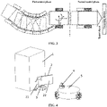
- FIG. 4 is a schematic diagram of the point stabilization system of the embodiment as shown in FIG. 1 .
- the target object 2 is disposed on a processing device 1.
- the mobile robot 5 may acquire the contour of an object in a preset range by using a lidar sensor.
- the position of the target object is determined when it is determined that the contour of the object is the contour of the target object.
- the target object 2 of FIG. 4 includes a first mounting plate 21 and a second mounting plate 22 having a length greater than or equal to a preset length.
- One end of the first mounting plate 21 and one end of the second mounting plate 22 are fixedly connected to each other to form an opening angle ⁇ greater than a preset angle.
- the preset length is 12 cm and the preset angle is 120 degrees.
- the target object may be of other shapes.
- the target object of FIG. 4 is easy to deploy in practical industrial applications.
- the position of the target object may be determined by laser ranging.
- whether the object is the target object is determined according to the contour of the object, that is, whether the target object is recognized is determined according to the geometric features of the object; the robustness is relatively strong.
- the mobile robot may acquire the position of the target object in other manners, for example, according to information input by the user.
- step 120 a first displacement of the robot relative to the target object is determined according to the position of the target object and the initial position of the robot.
- step 130 the target motion rate and the target motion direction of the robot are determined according to the to-be-offset displacement of the first displacement and a second displacement of the target object relative to a target point, and the mapping relation of the motion rate, the motion direction and the to-be-offset displacement.
- step 140 the current position of the robot is determined according to the target motion rate and the target motion direction of the robot, and the current position is used as the initial position and the process returns to step 120 until the distance between the current position of the robot and the position of the target point is less than the preset threshold.
- the first displacement of the robot relative to the target object is determined according to the position of the target object and the initial position of the robot. Specifically, that is, the magnitude of the first displacement and the direction of the first displacement are determined according to the position of the target object and the initial position of the robot.
- the current position of the robot is updated in real time. In each cycle, the control amount of the robot, that is, the target motion rate and the target motion direction of the robot, is determined according to the first displacement and the second displacement. Then the current position of the robot is determined according to the control amount of the robot.
- the set threshold range varies with different application scenarios. The smaller the set threshold range, the higher the corresponding precision.
- the threshold for a scenario with high precision is at millimeter level (1-10 mm) while the threshold for a scenario with general precision is at centimeter level (1-10 cm).
- the position of the target object does not vary during a complete point stabilization control process.
- the second displacement of the target object relative to the target point does not vary either. In this process, what varies is the current position of the robot.
- FIG. 2 is a block diagram of the point stabilization control method for a mobile robot of the embodiment as shown in FIG. 1 .
- the block diagram of the point stabilization control method for a mobile robot shows a feedback control process: a target value and a feedback value are input, where the target value is the first displacement and the feedback value is the first displacement in this embodiment; the error is determined according to the target value and the feedback value, and the control amount, that is, the target motion rate and the target motion direction of the robot, is determined according to the error and a control algorithm; the robot moves according to the target motion rate and the target motion direction; the position after the motion is marked and the sensor acquires the features and the position of the target object; a new feedback value is determined according to the position of the robot after the motion and the position of the target object by using a positioning algorithm.
- this feedback control method real-time precise control of the robot is achieved.
- the step of determining the target motion rate and the target motion direction of the robot according to the first displacement and the second displacement includes determining the to-be-offset position of the robot according to the first displacement and the second displacement and determining the target motion rate and the target motion direction according to the to-be-offset position and the mapping relation of the motion rate, the motion direction and the to-be-offset position.
- the mapping relation of the control amount and the offset position is preset. This mapping may be determined according to Proportion Integral Derivative (PID) control.
- PID Proportion Integral Derivative
- the to-be-offset position of the robot is determined according to the vector difference between the first displacement and the second displacement, where the to-be-offset position includes the to-be-offset angle and the to-be-offset distance; and then the control amount corresponding to the to-be-offset position, that is, the target motion rate and the target motion direction, is determined according to the set mapping relation.
- control amount of the robot may be determined according to the algorithm of an artificial vector field. This implementation will be described in detail in other embodiments.
- each of the positions involved in this embodiment is a vector including a size and a direction, that is, coordinate values of the position.
- FIG. 3 is a diagram of a point stabilization control process of the embodiment as shown in FIG. 1 .
- the point stabilization control process of this embodiment is divided into two phases: a first control phase where when the distance between the robot and the target object is greater than the set threshold, the target motion rate and the target motion direction are adjusted significantly (that is, to be greater than the adjustment threshold) so that the angular deviation of the mobile robot is relatively small; and a second control phase where when the distance between the robot and the target object is less than or equal to the set threshold, the target motion rate and the target motion direction are adjusted slightly (that is, to be less than or equal to the adjustment threshold) so that the robot reaches the target point.
- FIG. 5 illustrates schematic diagrams of the wheel system of the mobile robot of the embodiment as shown in FIG. 1 .
- the wheel system of the robot 5 of FIG. 4 is omni wheels
- the wheel system of the robot 7 of FIG. 5A is Mecanum wheels
- the wheel system of the robot 6 of FIG. 5B is differential wheels
- the wheel system of the robot 8 of FIG. 5C is helms.
- the point stabilization control system of FIG. 4 further includes a cross sliding table adjustable mechanism 3.
- the mechanism is configured to adjust the position of the robot after the robot reaches the target point so that the robot can operate the processing device more precisely.
- the point stabilization control method for a mobile robot includes acquiring the position of a target object; determining a first displacement of the robot relative to the target object according to the position of the target object and the initial position of the robot; determining the to-be-offset displacement of the robot according to the first displacement and a second displacement of the target object relative to a target point and determining the target motion rate and the target motion direction of the robot according to the to-be-offset displacement and the mapping relation of the motion rate, the motion direction and the to-be-offset displacement; determining the current position of the robot according to the target motion rate and the target motion direction; and using the current position as the initial position and returning to the steps from determining the first displacement of the robot relative to the target object according to the position of the target object and the initial position of the robot to determining the current position of the robot according to the target motion rate and the target motion direction until the distance between the current position of the robot and the position of the target point is less than the preset threshold.
- the control amount of the robot is
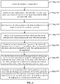
- FIG. 6 is a flowchart of a point stabilization control method for a mobile robot according to another embodiment. Based on the embodiment as shown in FIG. 1 , the steps included in step 120 are described in detail in this embodiment. As shown in FIG. 6 , the point stabilization control method for a mobile robot provided in this embodiment includes the steps described below.
- step 610 the position of a target object is acquired.
- step 610 The technical principle and implementation process of step 610 are similar to those of step 110 and will not be repeated here.
- a first displacement of the robot relative to the target object is determined according to the position of the target object and the initial position of the robot.
- step 620 The technical principle and implementation process of step 620 are similar to those of step 120 and will not be repeated here.
- step 630 the to-be-offset position of the robot is determined according to the first displacement and the second displacement.
- the to-be-offset position of the robot is determined according to the vector difference between the first displacement and the second displacement.
- step 640 the current position of the robot in the discretized artificial vector field is determined according to the to-be-offset displacement.
- the discretized artificial vector field is formed through discretization of an artificial vector field constructed according to to-be-offset displacement which is determined for the first time and the position of the target point.
- the position of the target point is an origin in the discretized artificial vector field.
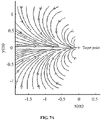
- FIG. 7A is a schematic diagram of the artificial vector field of the embodiment as shown in FIG. 6 .
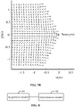
- FIG. 7B is a schematic diagram of the discretized artificial vector field of the embodiment as shown in FIG. 6 .
- the artificial vector field is constructed according to the to-be-offset position determined for the first time and the position of the target point.
- the target point is set at the origin.
- the vector field is continuous.
- the artificial vector field equalizes the robot into particles.
- the robot may be located at any position in the coordinate system.
- the potential function of the artificial vector field is used to determine the vector corresponding to the robot and thus to determine the direction of the forward motion of the robot.
- the controller is built using the artificial vector field. It is assumed that the target point is attractive in the desired angular direction, and when the robot deviates from this direction, an imaginary force enables the robot to automatically moves towards this direction.
- the to-be-offset position is the vector difference between the first displacement and the second displacement.
- the to-be-offset position is substantially the vector difference between the robot and the target point.
- the target point is the origin, so the current position of the robot in the discretized artificial vector field can be determined according to the position of the target point in the discretized artificial vector field and the to-be-offset position.
- step 650 the target motion track sequence of the robot in the discretized artificial vector field is determined according to the current position of the robot in the discretized artificial vector field and the position of the target point.
- the target motion track sequence includes a plurality of motion track points.
- the target motion track sequence of the robot in the discretized artificial vector field according to the current position and the position of the target point.
- mapping relation of the position of the robot in the discretized artificial vector field and the deflection angle of the robot is determined according to empirical data.
- the mapping relation of the position of the robot in the discretized artificial vector field and the deflection angle of the robot is determined according to a machine learning algorithm.
- the mapping relation may be determined using a machine learning algorithm.
- the learning process is as follows: an initial mapping is established; point stabilization control of the robot is performed according to the mapping and by use of the artificial vector field, the mapping is adjusted according to the error between the final position of the robot and the position of the target point; and for the purpose of reducing the error, an updated mapping is acquired, and with the updated mapping as the mapping, the step of the "point stabilization control method" is performed again until the final error is less than the preset error threshold.
- the finalized mapping is used as the mapping applied in the actual point stabilization control process.
- mapping is determined according to machine learning
- the determined mapping relation of the position of the robot in the discretized artificial vector field and the deflection angle of the robot is more accurate and the precision of point stabilization control is further improved.
- the target motion track sequence is determined according to the actual deflection angle and the position of the target point, it is feasible to determine the target motion track sequence according to a preset algorithm of the discretized artificial vector field.
- step 660 the first motion track point in the target motion track sequence in the direction away from the origin is used as a subtarget point, and the target motion rate and the target motion direction of the robot are determined according to the position of the subtarget point and the current position of the robot in the discretized artificial vector field.
- a subtarget point is selected after the target motion track sequence is determined.
- the subtarget point is the first motion track point in the target motion track sequence in the direction away from the origin.
- the positions of the motion track points included in the target motion track sequence are also known.
- the target motion rate and the target motion direction of the robot are determined according to the position of the subtarget point and the current position of the robot in the discretized artificial vector field.
- the target motion rate and the target motion direction of the robot may be determined according to the position of the subtarget point and the current position of the robot in the discretized artificial vector field by use of the preset algorithm of the discretized artificial vector field.
- step 670 the current position of the robot is determined according to the target motion rate and the target motion direction of the robot, and the current position is used as the initial position and the process returns to step 620 until the distance between the current position of the robot and the position of the target point is less than the preset threshold.
- the target motion track sequences determined by steps 620 through 650 are different with the update of the current position of the robot.
- the first motion track point in the target motion track sequence in the direction away from the origin is used as a subtarget point, and the target motion rate and the target motion direction of the robot are determined according to the position of the subtarget point and the current position of the robot in the discretized artificial vector field.
- the process of determining the current position of the robot according to the target motion rate and the target motion direction of the robot is the same as the process of step 120 and will not repeated here.
- the point stabilization control method for a mobile robot includes determining the target motion track sequence of the robot in the discretized artificial vector field according to the current position of the robot in the discretized artificial vector field and the position of the target point; and using the first motion track point in the target motion track sequence in the direction away from the origin as a subtarget point and determining the target motion rate and the target motion direction of the robot according to the position of the subtarget point and the current position of the robot in the discretized artificial vector field.
- the first motion track point in the target motion track sequence is used as a subtarget point, and the target motion rate and the target motion direction of the robot are determined according to the position of the subtarget point and the current position of the robot in the discretized artificial vector field.
- the target motion track sequence is split so that a finer control is achieved and the precision of point stabilization control is further improved.
- FIG. 8 is a structure diagram of a point stabilization control apparatus for a mobile robot according to this embodiment.
- the point stabilization control apparatus for a mobile robot provided in this embodiment includes an acquisition module 81 and a determination module 82.
- the acquisition module 81 is configured to acquire the position of a target object.
- the target object includes a first mounting plate and a second mounting plate, which have a length greater than or equal to a preset length, where one end of the first mounting plate and one end of the second mounting plate are fixedly connected to each other to form an opening angle greater than a preset angle.
- the preset length is 12 cm and the preset angle is 120 degrees.
- the acquisition module 81 is configured to acquire the contour of an object in a preset range by using a lidar sensor; and to determine the position of the target object when it is determined that the contour of the object is the contour of the target object.
- the determination module 82 is configured to determine a first displacement of the robot relative to the target object according to the position of the target object and the initial position of the robot; to determine the target motion rate and the target motion direction of the robot according to the first displacement and a second displacement of the target object relative to a target point; to determine the current position of the robot according to the target motion rate and the target motion direction of the robot; and to use the current position as the initial position and return to the steps from determining the first displacement of the robot relative to the target object according to the position of the target object and the current position of the robot to determining the current position of the robot according to the target motion rate and the target motion direction until the distance between the current position of the robot and the position of the target point is less than the preset threshold.
- the determination module 82 is configured to determine the target motion rate and the target motion direction of the robot according to the second displacement of the target object relative to the target point and the first displacement.
- the to-be-offset position of the robot is determined according to the first displacement and the second displacement, and the target motion rate and the target motion direction of the robot are determined according to the to-be-offset position and the mapping relation of the motion rate, the motion direction and the to-be-offset position.
- the robot uses any one of the following wheel systems: omni wheels, differential wheels, Mecanum wheels and helms.
- the point stabilization control apparatus for a mobile robot provided in this embodiment can perform the point stabilization control method for a mobile robot provided in the embodiment as shown in FIG. 1 .
- the point stabilization control apparatus has function modules and beneficial effects corresponding to the point stabilization control method.
- FIG. 9 is a structure diagram of a point stabilization control apparatus for a mobile robot according to another embodiment. Based on the embodiment as shown in FIG. 8 , the submodules included in the determination module 82 are described in detail in this embodiment. As shown in FIG. 9 , in this embodiment, the determination module 82 determines the target motion rate and the target motion direction of the robot after the determination according to the second displacement of the target object relative to a target point and the first displacement, and the determination module 82 includes a first determination submodule 821, a second determination submodule 822, a third determination submodule 823 and a fourth determination submodule 824.
- the first determination submodule 821 is configured to determine the to-be-offset position of the robot according to the first displacement and the second displacement.
- the second determination submodule 822 is configured to determine the current position of the robot in the discretized artificial vector field according to the to-be-offset position.
- the discretized artificial vector field is formed through discretization of an artificial vector field constructed according to the first determined to-be-offset position and the position of the target point and the position of the target point is the origin in the discretized artificial vector field.
- the third determination submodule 823 is configured to determine the target motion track sequence of the robot in the discretized artificial vector field according to the current position of the robot in the discretized artificial vector field and the position of the target point.
- the target motion track sequence includes a plurality of motion track points.
- the third determination submodule 823 is configured to determine the actual deflection angle of the robot in the discretized artificial vector field according to the current position of the robot in the discretized artificial vector field and the mapping relation of the position of the robot in the discretized artificial vector field and the deflection angle of the robot; and to determine the target motion track sequence according to the actual deflection angle and the position of the target point.
- the mapping relation of the position of the robot in the discretized artificial vector field and the deflection angle of the robot is configured to be determined according to empirical data or a machine learning algorithm.
- the fourth determination submodule 824 is configured to use the first motion track point in the target motion track sequence in the direction away from the origin as a subtarget point and to determine the target motion rate and the target motion direction of the robot according to the position of the subtarget point and the current position of the robot in the discretized artificial vector field.
- the point stabilization control apparatus for a mobile robot provided in this embodiment can perform the point stabilization control method for a mobile robot provided in the embodiment as shown in FIG. 6 .
- the point stabilization control apparatus has function modules and beneficial effects corresponding to the point stabilization control method.
- FIG. 10 is a structure diagram of an electronic device according to this embodiment.
- the electronic device includes a processor 70 and a memory 71.
- one or more processors 70 are provided.
- FIG. 10 uses an example in which one processor 70 is provided.
- the processor 70 and the memory 71 may be connected by a bus or connected in other manners.
- FIG. 10 uses an example in which a bus is used.
- the memory 71 is configured to store a software program, a computer-executable program and a module such as a program instruction and a module (for example, the acquisition module 81 and the determination module 82 in the point stabilization control apparatus for a mobile robot) corresponding to the point stabilization control method for a mobile robot of this embodiment.
- the processor 70 executes the software program, instruction and module stored in the memory 71 to perform function applications and data processing of the electronic device, that is, to implement the point stabilization control method for a mobile robot.
- the memory 71 may include a program storage region and a data storage region, where the program storage region may store an operating system and an application program required by at least one function while the data storage region may store data created depending on use of a terminal.
- the memory 71 may include a high-speed random access memory and a nonvolatile memory, such as at least one disk memory, a flash memory or other nonvolatile solid-state memories.
- the memory 71 may further include a memory disposed remote from the processor 70. The remote memory may be connected to a device/terminal/server via a network. Examples of the preceding network include, but are not limited to, the Internet, an intranet, a local area network, a mobile communication network or a combination thereof.
- This embodiment further provides a storage medium containing a computer-executable instruction that, when executed by a computer processor, implements a point stabilization control method for a mobile robot.
- the method includes acquiring the position of a target object; determining a first displacement of the robot relative to the target object according to the position of the target object and the initial position of the robot; determining the to-be-offset displacement of the robot according to the first displacement and a second displacement of the target object relative to a target point and determining the target motion rate and the target motion direction of the robot according to the to-be-offset displacement and the mapping relation of the motion rate, the motion direction and the to-be-offset displacement; determining the current position of the robot according to the target motion rate and the target motion direction; and using the current position as the initial position and returning to the step of determining the first displacement of the robot relative to the target object according to the position of the target object and the initial position of the robot to the step of determining the current position of the robot according to the target motion rate and the target motion direction until the distance between the current position of the robot and the position of the target point is less than the preset threshold.
- the computer software product may be stored in a computer-readable storage medium such as a read-only memory (ROM), a random access memory (RAM), a flash memory, a hard disk or an optical disk.
- the computer software product includes instructions configured to cause a device (which may be a network device such as a personal computer or a server) to perform the point stabilization control method for a mobile robot described in the preceding embodiments.
Landscapes
- Engineering & Computer Science (AREA)
- Robotics (AREA)
- Mechanical Engineering (AREA)
- Physics & Mathematics (AREA)
- Radar, Positioning & Navigation (AREA)
- Remote Sensing (AREA)
- Aviation & Aerospace Engineering (AREA)
- General Physics & Mathematics (AREA)
- Automation & Control Theory (AREA)
- Human Computer Interaction (AREA)
- Optics & Photonics (AREA)
- Electromagnetism (AREA)
- Manipulator (AREA)
- Control Of Position, Course, Altitude, Or Attitude Of Moving Bodies (AREA)
Description
- The present disclosure relates to the robot control technology, for example, a point stabilization control method and apparatus for a mobile robot.
- With the development of the communication technology and the electronic technology, mobile robots have been widely used in industrial environments. For example, automatic loading has been achieved through mobile robots or automatic charging of mobile robots has been achieved. In the industrial application of mobile robots, how to implement point stabilization control of mobile robots is very important.
- In the related art, the point stabilization control of a robot is implemented using the following method: acquiring the actual position and the target position of the robot, and controlling the motion direction and the motion distance of the robot according to the offset between the actual position and the target position of the robot.
- However, in the preceding point stabilization control method, it is impossible to adjust the offset according to the actual motion direction and motion distance of the robot, resulting in poor control precision.
- XP055321836 (S Oh ET AL: "Autonomous Battery Recharging for Indoor Mobile Robots", 30 August 2000) describes a method for automatically recharging the batteries on a mobile robot. The robot used in this project is the Nomadic Technologies Nomad XR4000 mobile robot. The battery recharging system was implemented using the robot's built-in sensors to control docking with a simple recharging station. The recharging station has an AC power plug, an infra-red beacon and a target designed for detection by the Sick Laser Range Finder. The robot's IR sensors perform the beacon detection. The robot moves towards the beacon until the laser target pattern is visible to the Sick laser. The system is currently under development and undergoing its performance testing.
- The present disclosure provides a point stabilization control method and apparatus for a mobile robot according to
independent claims 1 and 9, which solve the problem of poor control precision of a point stabilization control method for a mobile robot in the related art. - An embodiment provides a point stabilization control method for a mobile robot. The method includes acquiring a position of a target object; determining a first displacement of the robot relative to the target object according to the position of the target object and an initial position of the robot; determining a first displacement of the robot relative to the target object according to the position of the target object and an initial position of the robot; determining an offset displacement of the robot relative to a target point according to the first displacement and according to a second displacement of the target object relative to the target point; and determining a control motion rate and a control motion direction of the robot, on the basis of the offset displacement and a mapping relation of a motion rate of the robot, a motion direction of the robot and the offset displacement; determining a current position of the robot, on the basis of the control motion rate and the control motion direction; and using the current position of the robot as the initial position and repeating the steps from the step of determining the first displacement of the robot relative to the target object according to the position of the target object and the initial position of the robot up to the step of determining the current position of the robot on the basis of the control motion rate and the control motion direction, until a distance between a real position of the robot and a position of the target point is less than a preset threshold. The step of determining the offset displacement of the robot relative to the target point according to the first displacement and according to the second displacement of the target object relative to the target point, and determining the control motion rate and the control motion direction of the robot, on the basis of the offset displacement and the mapping relation of the motion rate of the robot, the motion direction of the robot and the offset displacement comprises: determining the offset displacement of the robot relative to the target point according to the first displacement and according to the second displacement of the target object relative to the target point; determining a current position of the robot in a discretized artificial vector field, on the basis of the offset displacement, wherein the discretized artificial vector field is formed through discretizing an artificial vector field constructed according to an offset displacement of the robot relative to the target point which is determined for the first time and the position of the target point, and the position of the target point is an origin in the discretized artificial vector field; determining a target motion track sequence of the robot in the discretized artificial vector field, on the basis of the current position of the robot in the discretized artificial vector field and the position of the target point, wherein the target motion track sequence comprises a plurality of motion track points; and using a first motion track point in the target motion track sequence in a direction away from the origin as a sub-target point, and determining the control motion rate and the control motion direction of the robot, on the basis of a position of the sub-target point and the current position of the robot in the discretized artificial vector field.
- An embodiment provides a point stabilization control apparatus for a mobile robot. The apparatus includes a determination module, which is configured to determine a first displacement of the robot relative to the target object according to the position of the target object and an initial position of the robot; to determine an offset displacement of the robot relative to a target point according to the first displacement and according to a second relative position of the target object relative to the target point, to determine a control motion rate and a control motion direction of the robot on the basis of the offset displacement and a mapping relation of a motion rate of the robot, a motion direction of the robot and the offset displacement; to determine a current position of the robot on the basis of the control motion rate and the control motion direction; and to use the current position of the robot as the initial position and to repeat to the steps from the step of determining the first displacement of the robot relative to the target object according to the position of the target object and the initial position of the robot up to the step of determining the current position of the robot on the basis of the control motion rate and the control motion direction until a distance between real position of the robot and a position of the target point is less than a preset threshold. The determination module comprises a first determination submodule, a second determination submodule, a third determination submodule and a fourth determination submodule, wherein, the first determination submodule is configured to determine the offset displacement position of the robot relative to the target point according to the first displacement and according to the second displacement of the target object relative to the target point; the second determination submodule is configured to determine a current position of the robot in a discretized artificial vector field according to the offset displacement, wherein the discretized artificial vector field is formed through discretizing an artificial vector field constructed according to an offset displacement of the robot relative to the target point which is determined for the first time and the position of the target point, and the position of the target point is an origin in the discretized artificial vector field; the third determination submodule is configured to determine a target motion track sequence of the robot in the discretized artificial vector field, on the basis of the current position of the robot in the discretized artificial vector field and the position of the target point, wherein the target motion track sequence comprises a plurality of motion track points; and the fourth determination submodule is configured to use a first motion track point in the target motion track sequence in a direction away from the origin as a sub-target point and to determine the control motion rate and the control motion direction of the robot, on the basis of a position of the sub-target point and the current position of the robot in the discretized artificial vector field.
- An embodiment provides an electronic device. The electronic device includes at least one processor; and a memory, which is configured to store at least one program which, when executed by the at least one processor, causes the at least one processor to perform the point stabilization control method for a mobile robot as described in the first aspect.
- An embodiment provides a computer-readable storage medium, which is configured to store at least one computer program which, when executed by at least one processor, perform the point stabilization control method for a mobile robot as described in the first aspect.
- Further improvements and embodiments are provided in the dependent claims.
-
-
FIG. 1 is a flowchart of a point stabilization control method for a mobile robot according to an embodiment. -
FIG. 2 is a flowchart of the point stabilization control method for a mobile robot of the embodiment as shown inFIG. 1 . -
FIG. 3 is a diagram of a point stabilization control process of the embodiment as shown inFIG. 1 . -
FIG. 4 is a schematic diagram of the point stabilization system of the embodiment as shown inFIG. 1 . -
FIG. 5A is a schematic diagram of a first wheel system of the mobile robot of the embodiment as shown inFIG. 1 . -
FIG. 5B is a schematic diagram of a second wheel system of the mobile robot of the embodiment as shown inFIG. 1 . -
FIG. 5C is a schematic diagram of a third wheel system of the mobile robot of the embodiment as shown inFIG. 1 . -
FIG. 6 is a flowchart of a point stabilization control method for a mobile robot according to another embodiment. -
FIG. 7A is a schematic diagram of the artificial vector field of the embodiment as shown inFIG. 6 . -
FIG. 7B is a schematic diagram of the discretized artificial vector field of the embodiment as shown inFIG. 6 . -
FIG. 8 is a structure diagram of a point stabilization control apparatus for a mobile robot according to an embodiment. -
FIG. 9 is a structure diagram of a point stabilization control apparatus for a mobile robot according to another embodiment. -
FIG. 10 is a structure diagram of an electronic device according to an embodiment. -
FIG. 1 is a flowchart of a point stabilization control method for a mobile robot according to this embodiment. As shown inFIG. 1 , the point stabilization control method for a mobile robot provided in this embodiment includes the steps described below. - In
step 110, the position of a target object is acquired. - The point stabilization control method for a mobile robot of this embodiment is to study how to design and implement feedback control such that the robot maintains the desired posture. In practical industrial applications, point stabilization control problems often occur in a scenario where a mobile robot reaches the desired posture with relatively high precision, such as automatic loading and automatic charging scenarios.
- In this embodiment, the method is performed by the point stabilization control system of the mobile robot and the system runs in the mobile robot.
- During the control process, the mobile robot needs to acquire the position of the target object. The target object here refers to an object having a fixed distance from the target point to which the mobile robot is to reach. The target object may have a fixed shape that facilitates recognition by the mobile robot.
-
FIG. 4 is a schematic diagram of the point stabilization system of the embodiment as shown inFIG. 1 . As shown inFIG. 4 , thetarget object 2 is disposed on aprocessing device 1. Themobile robot 5 may acquire the contour of an object in a preset range by using a lidar sensor. The position of the target object is determined when it is determined that the contour of the object is the contour of the target object. Thetarget object 2 ofFIG. 4 includes afirst mounting plate 21 and asecond mounting plate 22 having a length greater than or equal to a preset length. One end of thefirst mounting plate 21 and one end of thesecond mounting plate 22 are fixedly connected to each other to form an opening angle α greater than a preset angle. The preset length is 12 cm and the preset angle is 120 degrees. The target object may be of other shapes. The target object ofFIG. 4 is easy to deploy in practical industrial applications. - In an implementation, when the
lidar sensor 4 determines that the contour of the acquired object is the contour of thetarget object 2, the position of the target object may be determined by laser ranging. - In this implementation, whether the object is the target object is determined according to the contour of the object, that is, whether the target object is recognized is determined according to the geometric features of the object; the robustness is relatively strong.
- In another implementation, the mobile robot may acquire the position of the target object in other manners, for example, according to information input by the user.
- In
step 120, a first displacement of the robot relative to the target object is determined according to the position of the target object and the initial position of the robot. - In
step 130, the target motion rate and the target motion direction of the robot are determined according to the to-be-offset displacement of the first displacement and a second displacement of the target object relative to a target point, and the mapping relation of the motion rate, the motion direction and the to-be-offset displacement. - In
step 140, the current position of the robot is determined according to the target motion rate and the target motion direction of the robot, and the current position is used as the initial position and the process returns to step 120 until the distance between the current position of the robot and the position of the target point is less than the preset threshold. - In an embodiment, after the position of the target object is acquired, the first displacement of the robot relative to the target object is determined according to the position of the target object and the initial position of the robot. Specifically, that is, the magnitude of the first displacement and the direction of the first displacement are determined according to the position of the target object and the initial position of the robot. In
step 120, the current position of the robot is updated in real time. In each cycle, the control amount of the robot, that is, the target motion rate and the target motion direction of the robot, is determined according to the first displacement and the second displacement. Then the current position of the robot is determined according to the control amount of the robot. With this current position used as the initial position described instep 120, the preceding steps are repeated until the distance between the current position of the robot and the position of the target point is less than the preset threshold. In this way, the point stabilization control of the robot is completed. The set threshold range varies with different application scenarios. The smaller the set threshold range, the higher the corresponding precision. The threshold for a scenario with high precision is at millimeter level (1-10 mm) while the threshold for a scenario with general precision is at centimeter level (1-10 cm). - In an embodiment, the position of the target object does not vary during a complete point stabilization control process. The second displacement of the target object relative to the target point does not vary either. In this process, what varies is the current position of the robot.
-
FIG. 2 is a block diagram of the point stabilization control method for a mobile robot of the embodiment as shown inFIG. 1 . As shown inFIG. 2 , the block diagram of the point stabilization control method for a mobile robot shows a feedback control process: a target value and a feedback value are input, where the target value is the first displacement and the feedback value is the first displacement in this embodiment; the error is determined according to the target value and the feedback value, and the control amount, that is, the target motion rate and the target motion direction of the robot, is determined according to the error and a control algorithm; the robot moves according to the target motion rate and the target motion direction; the position after the motion is marked and the sensor acquires the features and the position of the target object; a new feedback value is determined according to the position of the robot after the motion and the position of the target object by using a positioning algorithm. Through this feedback control method, real-time precise control of the robot is achieved. - In an implementation, the step of determining the target motion rate and the target motion direction of the robot according to the first displacement and the second displacement includes determining the to-be-offset position of the robot according to the first displacement and the second displacement and determining the target motion rate and the target motion direction according to the to-be-offset position and the mapping relation of the motion rate, the motion direction and the to-be-offset position.
- In this implementation, the mapping relation of the control amount and the offset position is preset. This mapping may be determined according to Proportion Integral Derivative (PID) control. In this implementation, first the to-be-offset position of the robot is determined according to the vector difference between the first displacement and the second displacement, where the to-be-offset position includes the to-be-offset angle and the to-be-offset distance; and then the control amount corresponding to the to-be-offset position, that is, the target motion rate and the target motion direction, is determined according to the set mapping relation.
- In another implementation, the control amount of the robot may be determined according to the algorithm of an artificial vector field. This implementation will be described in detail in other embodiments.
- When the current position of the robot is determined according to the target motion rate and the target motion direction of the robot, it is feasible to determine the motion distance according to the target motion rate of the robot and the duration in which the robot moves at the target motion rate, to determine the motion direction according to the target motion direction, and then to determine the current position of the robot according to the motion distance and the motion direction. Each of the positions involved in this embodiment is a vector including a size and a direction, that is, coordinate values of the position.
-
FIG. 3 is a diagram of a point stabilization control process of the embodiment as shown inFIG. 1 . As shown inFIG. 3 , the point stabilization control process of this embodiment is divided into two phases: a first control phase where when the distance between the robot and the target object is greater than the set threshold, the target motion rate and the target motion direction are adjusted significantly (that is, to be greater than the adjustment threshold) so that the angular deviation of the mobile robot is relatively small; and a second control phase where when the distance between the robot and the target object is less than or equal to the set threshold, the target motion rate and the target motion direction are adjusted slightly (that is, to be less than or equal to the adjustment threshold) so that the robot reaches the target point. - In this embodiment, the robot uses any one of the following wheel systems: omni wheels, differential wheels, Mecanum wheels and helms.
FIG. 5 illustrates schematic diagrams of the wheel system of the mobile robot of the embodiment as shown inFIG. 1 . Referring toFIGS. 4 and5 , the wheel system of therobot 5 ofFIG. 4 is omni wheels, the wheel system of therobot 7 ofFIG. 5A is Mecanum wheels, the wheel system of therobot 6 ofFIG. 5B is differential wheels, and the wheel system of therobot 8 ofFIG. 5C is helms. - In an embodiment, the point stabilization control system of
FIG. 4 further includes a cross sliding tableadjustable mechanism 3. The mechanism is configured to adjust the position of the robot after the robot reaches the target point so that the robot can operate the processing device more precisely. - The point stabilization control method for a mobile robot provided in this embodiment includes acquiring the position of a target object; determining a first displacement of the robot relative to the target object according to the position of the target object and the initial position of the robot; determining the to-be-offset displacement of the robot according to the first displacement and a second displacement of the target object relative to a target point and determining the target motion rate and the target motion direction of the robot according to the to-be-offset displacement and the mapping relation of the motion rate, the motion direction and the to-be-offset displacement; determining the current position of the robot according to the target motion rate and the target motion direction; and using the current position as the initial position and returning to the steps from determining the first displacement of the robot relative to the target object according to the position of the target object and the initial position of the robot to determining the current position of the robot according to the target motion rate and the target motion direction until the distance between the current position of the robot and the position of the target point is less than the preset threshold. In this way, the control amount of the robot is adjusted through closed-loop control so that point stabilization control is achieved and the control precision is improved.
-
FIG. 6 is a flowchart of a point stabilization control method for a mobile robot according to another embodiment. Based on the embodiment as shown inFIG. 1 , the steps included instep 120 are described in detail in this embodiment. As shown inFIG. 6 , the point stabilization control method for a mobile robot provided in this embodiment includes the steps described below. - In
step 610, the position of a target object is acquired. - The technical principle and implementation process of
step 610 are similar to those ofstep 110 and will not be repeated here. - In
step 620, a first displacement of the robot relative to the target object is determined according to the position of the target object and the initial position of the robot. - The technical principle and implementation process of
step 620 are similar to those ofstep 120 and will not be repeated here. - In
step 630, the to-be-offset position of the robot is determined according to the first displacement and the second displacement. - In an embodiment, the to-be-offset position of the robot is determined according to the vector difference between the first displacement and the second displacement.
- In
step 640, the current position of the robot in the discretized artificial vector field is determined according to the to-be-offset displacement. - The discretized artificial vector field is formed through discretization of an artificial vector field constructed according to to-be-offset displacement which is determined for the first time and the position of the target point. The position of the target point is an origin in the discretized artificial vector field.
- In an embodiment,
FIG. 7A is a schematic diagram of the artificial vector field of the embodiment as shown inFIG. 6 .FIG. 7B is a schematic diagram of the discretized artificial vector field of the embodiment as shown inFIG. 6 . As shown inFIG. 7A , the artificial vector field is constructed according to the to-be-offset position determined for the first time and the position of the target point. The target point is set at the origin. The vector field is continuous. Through discretization of the vector field, the discretized artificial vector field as shown inFIG. 7B is obtained. The artificial vector field equalizes the robot into particles. The robot may be located at any position in the coordinate system. The potential function of the artificial vector field is used to determine the vector corresponding to the robot and thus to determine the direction of the forward motion of the robot. The controller is built using the artificial vector field. It is assumed that the target point is attractive in the desired angular direction, and when the robot deviates from this direction, an imaginary force enables the robot to automatically moves towards this direction. - The to-be-offset position is the vector difference between the first displacement and the second displacement. The to-be-offset position is substantially the vector difference between the robot and the target point. In the discretized artificial vector field, the target point is the origin, so the current position of the robot in the discretized artificial vector field can be determined according to the position of the target point in the discretized artificial vector field and the to-be-offset position.
- In
step 650, the target motion track sequence of the robot in the discretized artificial vector field is determined according to the current position of the robot in the discretized artificial vector field and the position of the target point. - The target motion track sequence includes a plurality of motion track points.
- In an embodiment, after the current position of the robot in the discretized artificial vector field is determined, it is feasible to determine the target motion track sequence of the robot in the discretized artificial vector field according to the current position and the position of the target point.
- In an embodiment, it is feasible to determine the actual deflection angle of the robot in the discretized artificial vector field according to the current position of the robot in the discretized artificial vector field and the mapping relation of the position of the robot in the discretized artificial vector field and the deflection angle of the robot; and to determine the target motion track sequence according to the actual deflection angle and the position of the target point.
- In an embodiment, the mapping relation of the position of the robot in the discretized artificial vector field and the deflection angle of the robot is determined according to empirical data.
- In another embodiment, the mapping relation of the position of the robot in the discretized artificial vector field and the deflection angle of the robot is determined according to a machine learning algorithm. In this implementation, the mapping relation may be determined using a machine learning algorithm. The learning process is as follows: an initial mapping is established; point stabilization control of the robot is performed according to the mapping and by use of the artificial vector field, the mapping is adjusted according to the error between the final position of the robot and the position of the target point; and for the purpose of reducing the error, an updated mapping is acquired, and with the updated mapping as the mapping, the step of the "point stabilization control method" is performed again until the final error is less than the preset error threshold. The finalized mapping is used as the mapping applied in the actual point stabilization control process.
- In the case where the mapping is determined according to machine learning, the determined mapping relation of the position of the robot in the discretized artificial vector field and the deflection angle of the robot is more accurate and the precision of point stabilization control is further improved.
- When the target motion track sequence is determined according to the actual deflection angle and the position of the target point, it is feasible to determine the target motion track sequence according to a preset algorithm of the discretized artificial vector field.
- In
step 660, the first motion track point in the target motion track sequence in the direction away from the origin is used as a subtarget point, and the target motion rate and the target motion direction of the robot are determined according to the position of the subtarget point and the current position of the robot in the discretized artificial vector field. - In an embodiment, a subtarget point is selected after the target motion track sequence is determined. The subtarget point is the first motion track point in the target motion track sequence in the direction away from the origin. In an embodiment, after the target motion track sequence is determined, the positions of the motion track points included in the target motion track sequence are also known.
- Then the target motion rate and the target motion direction of the robot are determined according to the position of the subtarget point and the current position of the robot in the discretized artificial vector field. In this process, the target motion rate and the target motion direction of the robot may be determined according to the position of the subtarget point and the current position of the robot in the discretized artificial vector field by use of the preset algorithm of the discretized artificial vector field.
- In
step 670, the current position of the robot is determined according to the target motion rate and the target motion direction of the robot, and the current position is used as the initial position and the process returns to step 620 until the distance between the current position of the robot and the position of the target point is less than the preset threshold. - In this embodiment, the target motion track sequences determined by
steps 620 through 650 are different with the update of the current position of the robot. For the target motion track sequence determined for each time, the first motion track point in the target motion track sequence in the direction away from the origin is used as a subtarget point, and the target motion rate and the target motion direction of the robot are determined according to the position of the subtarget point and the current position of the robot in the discretized artificial vector field. - The process of determining the current position of the robot according to the target motion rate and the target motion direction of the robot is the same as the process of
step 120 and will not repeated here. - The point stabilization control method for a mobile robot provided in this embodiment includes determining the target motion track sequence of the robot in the discretized artificial vector field according to the current position of the robot in the discretized artificial vector field and the position of the target point; and using the first motion track point in the target motion track sequence in the direction away from the origin as a subtarget point and determining the target motion rate and the target motion direction of the robot according to the position of the subtarget point and the current position of the robot in the discretized artificial vector field. In this way, in the process of point stabilization control, the first motion track point in the target motion track sequence is used as a subtarget point, and the target motion rate and the target motion direction of the robot are determined according to the position of the subtarget point and the current position of the robot in the discretized artificial vector field. The target motion track sequence is split so that a finer control is achieved and the precision of point stabilization control is further improved.
-
FIG. 8 is a structure diagram of a point stabilization control apparatus for a mobile robot according to this embodiment. As shown inFIG. 8 , the point stabilization control apparatus for a mobile robot provided in this embodiment includes anacquisition module 81 and adetermination module 82. - The
acquisition module 81 is configured to acquire the position of a target object. - In an embodiment, the target object includes a first mounting plate and a second mounting plate, which have a length greater than or equal to a preset length, where one end of the first mounting plate and one end of the second mounting plate are fixedly connected to each other to form an opening angle greater than a preset angle. The preset length is 12 cm and the preset angle is 120 degrees.
- In an embodiment, the
acquisition module 81 is configured to acquire the contour of an object in a preset range by using a lidar sensor; and to determine the position of the target object when it is determined that the contour of the object is the contour of the target object. - The
determination module 82 is configured to determine a first displacement of the robot relative to the target object according to the position of the target object and the initial position of the robot; to determine the target motion rate and the target motion direction of the robot according to the first displacement and a second displacement of the target object relative to a target point; to determine the current position of the robot according to the target motion rate and the target motion direction of the robot; and to use the current position as the initial position and return to the steps from determining the first displacement of the robot relative to the target object according to the position of the target object and the current position of the robot to determining the current position of the robot according to the target motion rate and the target motion direction until the distance between the current position of the robot and the position of the target point is less than the preset threshold. - In an embodiment, the
determination module 82 is configured to determine the target motion rate and the target motion direction of the robot according to the second displacement of the target object relative to the target point and the first displacement. In an embodiment, the to-be-offset position of the robot is determined according to the first displacement and the second displacement, and the target motion rate and the target motion direction of the robot are determined according to the to-be-offset position and the mapping relation of the motion rate, the motion direction and the to-be-offset position. - In this embodiment, the robot uses any one of the following wheel systems: omni wheels, differential wheels, Mecanum wheels and helms.
- The point stabilization control apparatus for a mobile robot provided in this embodiment can perform the point stabilization control method for a mobile robot provided in the embodiment as shown in
FIG. 1 . The point stabilization control apparatus has function modules and beneficial effects corresponding to the point stabilization control method. -
FIG. 9 is a structure diagram of a point stabilization control apparatus for a mobile robot according to another embodiment. Based on the embodiment as shown inFIG. 8 , the submodules included in thedetermination module 82 are described in detail in this embodiment. As shown inFIG. 9 , in this embodiment, thedetermination module 82 determines the target motion rate and the target motion direction of the robot after the determination according to the second displacement of the target object relative to a target point and the first displacement, and thedetermination module 82 includes afirst determination submodule 821, asecond determination submodule 822, athird determination submodule 823 and afourth determination submodule 824. - The
first determination submodule 821 is configured to determine the to-be-offset position of the robot according to the first displacement and the second displacement. - The
second determination submodule 822 is configured to determine the current position of the robot in the discretized artificial vector field according to the to-be-offset position. - The discretized artificial vector field is formed through discretization of an artificial vector field constructed according to the first determined to-be-offset position and the position of the target point and the position of the target point is the origin in the discretized artificial vector field.
- The
third determination submodule 823 is configured to determine the target motion track sequence of the robot in the discretized artificial vector field according to the current position of the robot in the discretized artificial vector field and the position of the target point. - The target motion track sequence includes a plurality of motion track points.
- In an embodiment, the
third determination submodule 823 is configured to determine the actual deflection angle of the robot in the discretized artificial vector field according to the current position of the robot in the discretized artificial vector field and the mapping relation of the position of the robot in the discretized artificial vector field and the deflection angle of the robot; and to determine the target motion track sequence according to the actual deflection angle and the position of the target point. - The mapping relation of the position of the robot in the discretized artificial vector field and the deflection angle of the robot is configured to be determined according to empirical data or a machine learning algorithm.
- The
fourth determination submodule 824 is configured to use the first motion track point in the target motion track sequence in the direction away from the origin as a subtarget point and to determine the target motion rate and the target motion direction of the robot according to the position of the subtarget point and the current position of the robot in the discretized artificial vector field. - The point stabilization control apparatus for a mobile robot provided in this embodiment can perform the point stabilization control method for a mobile robot provided in the embodiment as shown in
FIG. 6 . The point stabilization control apparatus has function modules and beneficial effects corresponding to the point stabilization control method. -
FIG. 10 is a structure diagram of an electronic device according to this embodiment. As shown inFIG. 10 , the electronic device includes aprocessor 70 and amemory 71. In the electronic device, one ormore processors 70 are provided.FIG. 10 uses an example in which oneprocessor 70 is provided. In the electronic device, theprocessor 70 and thememory 71 may be connected by a bus or connected in other manners.FIG. 10 uses an example in which a bus is used. - As a computer-readable storage medium, the
memory 71 is configured to store a software program, a computer-executable program and a module such as a program instruction and a module (for example, theacquisition module 81 and thedetermination module 82 in the point stabilization control apparatus for a mobile robot) corresponding to the point stabilization control method for a mobile robot of this embodiment. Theprocessor 70 executes the software program, instruction and module stored in thememory 71 to perform function applications and data processing of the electronic device, that is, to implement the point stabilization control method for a mobile robot. - The
memory 71 may include a program storage region and a data storage region, where the program storage region may store an operating system and an application program required by at least one function while the data storage region may store data created depending on use of a terminal. In addition, thememory 71 may include a high-speed random access memory and a nonvolatile memory, such as at least one disk memory, a flash memory or other nonvolatile solid-state memories. In some embodiments, thememory 71 may further include a memory disposed remote from theprocessor 70. The remote memory may be connected to a device/terminal/server via a network. Examples of the preceding network include, but are not limited to, the Internet, an intranet, a local area network, a mobile communication network or a combination thereof. - This embodiment further provides a storage medium containing a computer-executable instruction that, when executed by a computer processor, implements a point stabilization control method for a mobile robot.
- The method includes acquiring the position of a target object; determining a first displacement of the robot relative to the target object according to the position of the target object and the initial position of the robot; determining the to-be-offset displacement of the robot according to the first displacement and a second displacement of the target object relative to a target point and determining the target motion rate and the target motion direction of the robot according to the to-be-offset displacement and the mapping relation of the motion rate, the motion direction and the to-be-offset displacement; determining the current position of the robot according to the target motion rate and the target motion direction; and using the current position as the initial position and returning to the step of determining the first displacement of the robot relative to the target object according to the position of the target object and the initial position of the robot to the step of determining the current position of the robot according to the target motion rate and the target motion direction until the distance between the current position of the robot and the position of the target point is less than the preset threshold.
- From the description of embodiments, it will be apparent to those skilled in the art that the present disclosure may be implemented by means of software and necessary general-purpose hardware or may be implemented by hardware. The computer software product may be stored in a computer-readable storage medium such as a read-only memory (ROM), a random access memory (RAM), a flash memory, a hard disk or an optical disk. The computer software product includes instructions configured to cause a device (which may be a network device such as a personal computer or a server) to perform the point stabilization control method for a mobile robot described in the preceding embodiments.
Claims (11)
- A point stabilization control method for a mobile robot, comprising:acquiring (Step 110, Step 610) a position of a target object (2);determining (Step 120, Step 620) a first displacement of the robot relative to the target object (2) according to the position of the target object (2) and an initial position of the robot;determining (Step 130) an offset displacement of the robot relative to a target point according to the first displacement and according to a second displacement of the target object (2) relative to the target point, anddetermining a control motion rate and a control motion direction of the robot, on the basis of the offset displacement and on the basis of a mapping relation of a motion rate of the robot, a motion direction of the robot and the offset displacement;determining (Step 140, Step 670) a current position of the robot, on the basis of the control motion rate and the control motion direction; andusing (Step 140, Step 670) the current position of the robot as the initial position andrepeating the steps from the step of determining the first displacement of the robot relative to the target object (2) according to the position of the target object (2) and the initial position of the robot up to the step of determining the current position of the robot on the basis of the control motion rate and the control motion direction, until a distance between the current position of the robot and a position of the target point is less than a preset threshold; andcharacterized in that:
the step of determining (Step 130) the offset displacement of the robot relative to the target point according to the first displacement and according to the second displacement of the target object (2) relative to the target point, and determining the control motion rate and the control motion direction of the robot, on the basis of the offset displacement and the mapping relation of the motion rate of the robot, the motion direction of the robot and the offset displacement comprises:determining (Step 640) a current position of the robot in a discretized artificial vector field on the basis of the offset displacement, wherein the discretized artificial vector field is formed through discretizing an artificial vector field constructed according to the offset displacement of the robot relative to the target point determined for the first time and the position of the target point, whereby the position of the target point is an origin in the discretized artificial vector field;determining (Step 650) a target motion track sequence of the robot in the discretized artificial vector field, on the basis of the current position of the robot in the discretized artificial vector field and the position of the target point, wherein the target motion track sequence comprises a plurality of motion track points; andusing (Step 660) a first motion track point in the target motion track sequence in a direction away from the origin as a sub-target point, and determining the control motion rate and the control motion direction of the robot on the basis of a position of the sub-target point and the current position of the robot in the discretized artificial vector field. - The method of claim 1, wherein the step of determining (Step 650) the target motion track sequence of the robot in the discretized artificial vector field, on the basis of the current position of the robot in the discretized artificial vector field and the position of the target point comprises:determining an actual deflection angle of the robot in the discretized artificial vector field, on the basis of the current position of the robot in the discretized artificial vector field and a mapping relation between a position of the robot in the discretized artificial vector field and a deflection angle of the robot; anddetermining the target motion track sequence, on the basis of the actual deflection angle and the position of the target point.
- The method of claim 2, wherein the mapping relation between the position of the robot in the discretized artificial vector field and the deflection angle of the robot is configured to be determined according to empirical data; or
the mapping relation between the position of the robot in the discretized artificial vector field and the deflection angle of the robot is configured to be determined according to a machine learning algorithm. - The method of any one of claims 1 to 3, wherein the target object (2) comprises a first mounting plate (21) and a second mounting plate (22) which have a length greater than or equal to a preset length, wherein one end of the first mounting plate (21) and one end of the second mounting plate (22) are fixedly connected to each other to form an opening angle greater than a preset angle.
- The method of claim 4, wherein the preset length is 12 cm and the preset angle is 120 degrees.
- The method of any one of claims 1 to 3, wherein the step of acquiring (Step 110) the position of the target object (2) comprises acquiring a contour of an object in a preset range by using a lidar sensor; and
determining a position of the object as the position of the target object (2) in response to determining that the contour of the object is a contour of the target object (2). - The method of any one of claims 1 to 3, wherein the offset displacement is a vector difference between the first displacement and the second displacement.
- The method of any one of claims 1 to 7, wherein the robot uses any one of the following wheel systems:
omni wheels, differential wheels, Mecanum wheels and helms. - A point stabilization control apparatus for a mobile robot, comprising:an acquisition module (81), which is configured to acquire a position of a target object (2); anda determination module (82), which is configured to determine a first displacement of the robot relative to the target object (2) according to the position of the target object (2) and an initial position of the robot;to determine an offset displacement of the robot relative to a target point according to the first displacement and according to a second displacement of the target object (2) relative to the target point and to determine a control motion rate and a control motion direction of the robot on the basis of the offset displacement and on the basis of a mapping relation of a motion rate of the robot, a motion direction of the robot and the offset displacement;to determine a current position of the robot on the basis of the control motion rate and the control motion direction; andto use the current position of the robot as the initial position;whereby the apparatus is further configured:to repeat the steps from the step of determining the first displacement of the robot relative to the target object (2) according to the position of the target object (2) and the initial position of the robot up to the step of determining the current position of the robot on the basis of the control motion rate and the control motion direction, until a distance between the current position of the robot and a position of the target point is less than a preset threshold; and characterized in that:the determination module (82) comprises a first determination submodule (821), a second determination submodule (822), a third determination submodule (823) and a fourth determination submodule (824), wherein,the first determination submodule (821) is configured to determine the offset displacement position of the robot relative to the target point according to the first displacement andaccording to the second displacement of the target object (2) relative to the target point;the second determination submodule (822) is configured to determine a current position of the robot in a discretized artificial vector field on the basis of the offset displacement, wherein the discretized artificial vector field is formed through discretizing an artificial vector field constructed according to the offset displacement of the robot relative to the target pointdetermined for the first time and the position of the target point, whereby the position of the targetpoint is an origin in the discretized artificial vector field;the third determination submodule (823) is configured to determine a target motion track sequence of the robot in the discretized artificial vector field, on the basis of the current position of the robot in the discretized artificial vector field and the position of the target point, whereinthe target motion track sequence comprises a plurality of motion track points; andthe fourth determination submodule (824) is configured to use a first motion track point in the target motion track sequence in a direction away from the origin as a sub-target point and todetermine the control motion rate and the control motion direction of the robot on the basis of a position of the sub-target point and the current position of the robot in the discretized artificial vector field.
- An electronic device, comprising:at least one processor (70); anda memory (71), which is configured to store at least one program which, when executed by the at least one processor (70), causes the at least one processor (70) to perform the point stabilization control method for a mobile robot of any one of claims 1 to 8.
- A computer-readable storage medium, which is configured to store a computer program which, when executed by a processor (70), perform the point stabilization control method for the mobile robot of any one of claims 1 to 7.
Applications Claiming Priority (3)
| Application Number | Priority Date | Filing Date | Title |
|---|---|---|---|
| CN201810827226 | 2018-07-25 | ||
| CN201810869740.7A CN109189060B (en) | 2018-07-25 | 2018-08-02 | Point stabilization control method and device for mobile robot |
| PCT/CN2018/115376 WO2020024478A1 (en) | 2018-07-25 | 2018-11-14 | Point stabilization control method and device for mobile robot |
Publications (3)
| Publication Number | Publication Date |
|---|---|
| EP3633480A1 EP3633480A1 (en) | 2020-04-08 |
| EP3633480A4 EP3633480A4 (en) | 2021-03-24 |
| EP3633480B1 true EP3633480B1 (en) | 2022-04-27 |
Family
ID=64920547
Family Applications (1)
| Application Number | Title | Priority Date | Filing Date |
|---|---|---|---|
| EP18923763.9A Active EP3633480B1 (en) | 2018-07-25 | 2018-11-14 | Point stabilization control method and device for mobile robot |
Country Status (5)
| Country | Link |
|---|---|
| US (1) | US11247336B2 (en) |
| EP (1) | EP3633480B1 (en) |
| CN (1) | CN109189060B (en) |
| SG (1) | SG11202002285VA (en) |
| WO (1) | WO2020024478A1 (en) |
Families Citing this family (12)
| Publication number | Priority date | Publication date | Assignee | Title |
|---|---|---|---|---|
| CN110525517A (en) * | 2019-08-27 | 2019-12-03 | 共享智能铸造产业创新中心有限公司 | The motion control method of omnidirectional's heavy duty mobile robot |
| CN112596440A (en) * | 2020-12-17 | 2021-04-02 | 广东顺联动漫科技有限公司 | Method, device and equipment for controlling object motion and storage medium |
| CN113253256B (en) * | 2021-06-04 | 2021-11-19 | 智道网联科技(北京)有限公司 | Monitoring method and device based on sensor fusion equipment and sensor fusion equipment |
| CN114102592B (en) * | 2021-11-24 | 2023-06-27 | 乐聚(深圳)机器人技术有限公司 | Robot protection control method, device and equipment based on motion state detection |
| CN114012732B (en) * | 2021-11-26 | 2023-03-31 | 北京云迹科技股份有限公司 | Robot control method, device, equipment and medium |
| US12358528B2 (en) * | 2022-04-26 | 2025-07-15 | Toyota Research Institute, Inc. | Producing a trajectory from a diverse set of possible movements |
| CN115401689B (en) * | 2022-08-01 | 2024-03-29 | 北京市商汤科技开发有限公司 | Distance measuring method and device based on monocular camera and computer storage medium |
| CN115847821B (en) * | 2022-10-24 | 2025-08-08 | 浙江工业大学 | A method for dynamically tracking the motion trajectory of a mobile printing robot |
| CN115958609B (en) * | 2023-03-16 | 2023-07-14 | 山东卓朗检测股份有限公司 | Instruction data security early warning method based on intelligent robot automatic control system |
| CN116449842B (en) * | 2023-04-21 | 2026-03-27 | 潍柴雷沃智慧农业科技股份有限公司 | Straight-line travel control methods, devices, and agricultural machinery |
| CN117601097B (en) * | 2023-11-29 | 2024-12-10 | 国网智能科技股份有限公司 | A track type inspection robot, motion positioning control system and method |
| CN118875604A (en) * | 2024-07-23 | 2024-11-01 | 北京城乡建设集团有限责任公司 | A high-stability steel structure welding robot and a fast welding control method |
Family Cites Families (21)
| Publication number | Priority date | Publication date | Assignee | Title |
|---|---|---|---|---|
| US6829568B2 (en) * | 2002-04-26 | 2004-12-07 | Simon Justin Julier | Method and apparatus for fusing signals with partially known independent error components |
| JP4944551B2 (en) | 2006-09-26 | 2012-06-06 | 日立オートモティブシステムズ株式会社 | Travel control device, travel control method, and travel control program |
| CN102087530B (en) * | 2010-12-07 | 2012-06-13 | 东南大学 | Vision navigation method of mobile robot based on hand-drawing map and path |
| CN102359784B (en) * | 2011-08-01 | 2013-07-24 | 东北大学 | Autonomous navigation and obstacle avoidance system and method of indoor mobile robot |
| KR101326889B1 (en) * | 2011-11-07 | 2013-11-11 | 현대자동차주식회사 | A method and system to control relative position among vehicles using dgps mobile reference station |
| US9367067B2 (en) * | 2013-03-15 | 2016-06-14 | Ashley A Gilmore | Digital tethering for tracking with autonomous aerial robot |
| US9798324B2 (en) * | 2014-07-18 | 2017-10-24 | Helico Aerospace Industries Sia | Autonomous vehicle operation |
| CN104354157B (en) * | 2014-10-29 | 2016-03-02 | 南京航空航天大学 | A kind of tire transfer robot and control method thereof |
| EP3057061B1 (en) * | 2015-02-16 | 2017-08-30 | Application Solutions (Electronics and Vision) Limited | Method and device for the estimation of car egomotion from surround view images |
| US20170108874A1 (en) | 2015-10-19 | 2017-04-20 | Aseco Investment Corp. | Vision-based system for navigating a robot through an indoor space |
| CN105929849B (en) * | 2016-04-28 | 2018-10-23 | 东南大学 | One kind is based on point quelling wheeled mobile robot target following control method |
| CN106647738A (en) | 2016-11-10 | 2017-05-10 | 杭州南江机器人股份有限公司 | Method and system for determining docking path of automated guided vehicle, and automated guided vehicle |
| US20180143641A1 (en) * | 2016-11-23 | 2018-05-24 | Futurewei Technologies, Inc. | Motion controlling method for an autonomous vehicle and a computer device |
| CN106843280B (en) * | 2017-02-17 | 2021-03-16 | 深圳市卓兴半导体科技有限公司 | Intelligent robot following system |
| JP6640777B2 (en) * | 2017-03-17 | 2020-02-05 | 株式会社東芝 | Movement control system, movement control device and program |
| US10606273B2 (en) * | 2017-04-20 | 2020-03-31 | Baidu Usa Llc | System and method for trajectory re-planning of autonomous driving vehicles |
| CN107085428B (en) | 2017-05-18 | 2020-03-10 | 广州视源电子科技股份有限公司 | Intelligent moving method, device, robot and storage medium |
| CN107300919B (en) | 2017-06-22 | 2021-06-15 | 中国科学院深圳先进技术研究院 | A robot and its travel control method |
| CN107703973B (en) * | 2017-09-11 | 2021-08-31 | 广州视源电子科技股份有限公司 | Track tracking method and device |
| JP7147142B2 (en) * | 2017-09-15 | 2022-10-05 | ソニーグループ株式会社 | CONTROL DEVICE, CONTROL METHOD, PROGRAM, AND MOVING OBJECT |
| CN108255174B (en) * | 2017-12-20 | 2021-03-16 | 北京理工华汇智能科技有限公司 | Robot path planning method and device |
-
2018
- 2018-08-02 CN CN201810869740.7A patent/CN109189060B/en active Active
- 2018-11-14 SG SG11202002285VA patent/SG11202002285VA/en unknown
- 2018-11-14 WO PCT/CN2018/115376 patent/WO2020024478A1/en not_active Ceased
- 2018-11-14 EP EP18923763.9A patent/EP3633480B1/en active Active
- 2018-11-14 US US16/628,491 patent/US11247336B2/en active Active
Also Published As
| Publication number | Publication date |
|---|---|
| US20210138644A1 (en) | 2021-05-13 |
| EP3633480A1 (en) | 2020-04-08 |
| US11247336B2 (en) | 2022-02-15 |
| EP3633480A4 (en) | 2021-03-24 |
| SG11202002285VA (en) | 2020-04-29 |
| WO2020024478A1 (en) | 2020-02-06 |
| CN109189060B (en) | 2021-01-12 |
| CN109189060A (en) | 2019-01-11 |
Similar Documents
| Publication | Publication Date | Title |
|---|---|---|
| US11247336B2 (en) | Point stabilization control method and apparatus for a mobile robot | |
| Schiavi et al. | Integration of active and passive compliance control for safe human-robot coexistence | |
| US11230001B2 (en) | Biped robot gait control method and biped robot | |
| CN106919171B (en) | Indoor robot positioning and navigation system and method | |
| CN108927801B (en) | Method and device for adjusting tail end attitude of mechanical arm | |
| CN105204515B (en) | The measurement parsing of unmanned plane independent landing and control method and device | |
| WO2019047415A1 (en) | Trajectory tracking method and device, storage medium, processor | |
| CN112256011A (en) | Regression guiding method, regression guiding device, mobile robot, and storage medium | |
| Guan et al. | Formation tracking of mobile robots under obstacles using only an active RGB-D camera | |
| Xia et al. | Control method of multi-AUV circular formation combining consensus theory and artificial potential field method | |
| CN119610127A (en) | Motion trajectory planning and obstacle avoidance method for a wheeled dual-arm humanoid robot | |
| Markdahl et al. | Distributed cooperative object attitude manipulation | |
| CN115229789B (en) | Teleoperation method for robot, robot and storage medium | |
| Li et al. | Hybrid Learning-Optimization Control Methods for Dual-Arm Robots in Cooperative Transportation Tasks | |
| CN107121128A (en) | A kind of measuring method and system of legged type robot terrain parameter | |
| Srivastava et al. | Range estimation and visual servoing of a dynamic target using a monocular camera | |
| CN121360920A (en) | Welding method and system for cooperative control of mobile chassis and mechanical arm of mobile welding platform | |
| HK40027063B (en) | Point stabilization control method and device for mobile robot | |
| WO2018214156A1 (en) | Method of correcting locomotion control command of robot, and related apparatus for same | |
| CN114754781A (en) | Map updating method, device, robot and medium | |
| Sadeghian et al. | Visual servoing with safe interaction using image moments | |
| HK40027063A (en) | Point stabilization control method and device for mobile robot | |
| Chen et al. | Vision-based high-precision assembly with force feedback | |
| Roditis et al. | Maintaining static stability and continuous motion in rough terrain hexapod locomotion without terrain mapping | |
| CN114734435B (en) | An encoder calibration method, device and system based on hypersphere |
Legal Events
| Date | Code | Title | Description |
|---|---|---|---|
| STAA | Information on the status of an ep patent application or granted ep patent |
Free format text: STATUS: UNKNOWN |
|
| STAA | Information on the status of an ep patent application or granted ep patent |
Free format text: STATUS: THE INTERNATIONAL PUBLICATION HAS BEEN MADE |
|
| PUAI | Public reference made under article 153(3) epc to a published international application that has entered the european phase |
Free format text: ORIGINAL CODE: 0009012 |
|
| STAA | Information on the status of an ep patent application or granted ep patent |
Free format text: STATUS: REQUEST FOR EXAMINATION WAS MADE |
|
| 17P | Request for examination filed |
Effective date: 20200103 |
|
| AK | Designated contracting states |
Kind code of ref document: A1 Designated state(s): AL AT BE BG CH CY CZ DE DK EE ES FI FR GB GR HR HU IE IS IT LI LT LU LV MC MK MT NL NO PL PT RO RS SE SI SK SM TR |
|
| AX | Request for extension of the european patent |
Extension state: BA ME |
|
| RAP1 | Party data changed (applicant data changed or rights of an application transferred) |
Owner name: BOZHON PRECISION INDUSTRY TECHNOLOGY CO., LTD. Owner name: SUZHOU BOZHON ROBOT CO., LTD |
|
| REG | Reference to a national code |
Ref country code: HK Ref legal event code: DE Ref document number: 40027063 Country of ref document: HK |
|
| A4 | Supplementary search report drawn up and despatched |
Effective date: 20210218 |
|
| RIC1 | Information provided on ipc code assigned before grant |
Ipc: G05D 1/02 20200101AFI20210212BHEP |
|
| DAV | Request for validation of the european patent (deleted) | ||
| DAX | Request for extension of the european patent (deleted) | ||
| GRAP | Despatch of communication of intention to grant a patent |
Free format text: ORIGINAL CODE: EPIDOSNIGR1 |
|
| STAA | Information on the status of an ep patent application or granted ep patent |
Free format text: STATUS: GRANT OF PATENT IS INTENDED |
|
| INTG | Intention to grant announced |
Effective date: 20211222 |
|
| GRAS | Grant fee paid |
Free format text: ORIGINAL CODE: EPIDOSNIGR3 |
|
| GRAA | (expected) grant |
Free format text: ORIGINAL CODE: 0009210 |
|
| STAA | Information on the status of an ep patent application or granted ep patent |
Free format text: STATUS: THE PATENT HAS BEEN GRANTED |
|
| AK | Designated contracting states |
Kind code of ref document: B1 Designated state(s): AL AT BE BG CH CY CZ DE DK EE ES FI FR GB GR HR HU IE IS IT LI LT LU LV MC MK MT NL NO PL PT RO RS SE SI SK SM TR |
|
| REG | Reference to a national code |
Ref country code: GB Ref legal event code: FG4D |
|
| REG | Reference to a national code |
Ref country code: CH Ref legal event code: EP |
|
| REG | Reference to a national code |
Ref country code: AT Ref legal event code: REF Ref document number: 1487425 Country of ref document: AT Kind code of ref document: T Effective date: 20220515 |
|
| REG | Reference to a national code |
Ref country code: DE Ref legal event code: R096 Ref document number: 602018034721 Country of ref document: DE |
|
| REG | Reference to a national code |
Ref country code: IE Ref legal event code: FG4D |
|
| REG | Reference to a national code |
Ref country code: LT Ref legal event code: MG9D |
|
| REG | Reference to a national code |
Ref country code: NL Ref legal event code: MP Effective date: 20220427 |
|
| REG | Reference to a national code |
Ref country code: AT Ref legal event code: MK05 Ref document number: 1487425 Country of ref document: AT Kind code of ref document: T Effective date: 20220427 |
|
| PG25 | Lapsed in a contracting state [announced via postgrant information from national office to epo] |
Ref country code: NL Free format text: LAPSE BECAUSE OF FAILURE TO SUBMIT A TRANSLATION OF THE DESCRIPTION OR TO PAY THE FEE WITHIN THE PRESCRIBED TIME-LIMIT Effective date: 20220427 |
|
| PG25 | Lapsed in a contracting state [announced via postgrant information from national office to epo] |
Ref country code: SE Free format text: LAPSE BECAUSE OF FAILURE TO SUBMIT A TRANSLATION OF THE DESCRIPTION OR TO PAY THE FEE WITHIN THE PRESCRIBED TIME-LIMIT Effective date: 20220427 Ref country code: PT Free format text: LAPSE BECAUSE OF FAILURE TO SUBMIT A TRANSLATION OF THE DESCRIPTION OR TO PAY THE FEE WITHIN THE PRESCRIBED TIME-LIMIT Effective date: 20220829 Ref country code: NO Free format text: LAPSE BECAUSE OF FAILURE TO SUBMIT A TRANSLATION OF THE DESCRIPTION OR TO PAY THE FEE WITHIN THE PRESCRIBED TIME-LIMIT Effective date: 20220727 Ref country code: LT Free format text: LAPSE BECAUSE OF FAILURE TO SUBMIT A TRANSLATION OF THE DESCRIPTION OR TO PAY THE FEE WITHIN THE PRESCRIBED TIME-LIMIT Effective date: 20220427 Ref country code: HR Free format text: LAPSE BECAUSE OF FAILURE TO SUBMIT A TRANSLATION OF THE DESCRIPTION OR TO PAY THE FEE WITHIN THE PRESCRIBED TIME-LIMIT Effective date: 20220427 Ref country code: GR Free format text: LAPSE BECAUSE OF FAILURE TO SUBMIT A TRANSLATION OF THE DESCRIPTION OR TO PAY THE FEE WITHIN THE PRESCRIBED TIME-LIMIT Effective date: 20220728 Ref country code: FI Free format text: LAPSE BECAUSE OF FAILURE TO SUBMIT A TRANSLATION OF THE DESCRIPTION OR TO PAY THE FEE WITHIN THE PRESCRIBED TIME-LIMIT Effective date: 20220427 Ref country code: ES Free format text: LAPSE BECAUSE OF FAILURE TO SUBMIT A TRANSLATION OF THE DESCRIPTION OR TO PAY THE FEE WITHIN THE PRESCRIBED TIME-LIMIT Effective date: 20220427 Ref country code: BG Free format text: LAPSE BECAUSE OF FAILURE TO SUBMIT A TRANSLATION OF THE DESCRIPTION OR TO PAY THE FEE WITHIN THE PRESCRIBED TIME-LIMIT Effective date: 20220727 Ref country code: AT Free format text: LAPSE BECAUSE OF FAILURE TO SUBMIT A TRANSLATION OF THE DESCRIPTION OR TO PAY THE FEE WITHIN THE PRESCRIBED TIME-LIMIT Effective date: 20220427 |
|
| PG25 | Lapsed in a contracting state [announced via postgrant information from national office to epo] |
Ref country code: RS Free format text: LAPSE BECAUSE OF FAILURE TO SUBMIT A TRANSLATION OF THE DESCRIPTION OR TO PAY THE FEE WITHIN THE PRESCRIBED TIME-LIMIT Effective date: 20220427 Ref country code: PL Free format text: LAPSE BECAUSE OF FAILURE TO SUBMIT A TRANSLATION OF THE DESCRIPTION OR TO PAY THE FEE WITHIN THE PRESCRIBED TIME-LIMIT Effective date: 20220427 Ref country code: LV Free format text: LAPSE BECAUSE OF FAILURE TO SUBMIT A TRANSLATION OF THE DESCRIPTION OR TO PAY THE FEE WITHIN THE PRESCRIBED TIME-LIMIT Effective date: 20220427 Ref country code: IS Free format text: LAPSE BECAUSE OF FAILURE TO SUBMIT A TRANSLATION OF THE DESCRIPTION OR TO PAY THE FEE WITHIN THE PRESCRIBED TIME-LIMIT Effective date: 20220827 |
|
| REG | Reference to a national code |
Ref country code: DE Ref legal event code: R097 Ref document number: 602018034721 Country of ref document: DE |
|
| PG25 | Lapsed in a contracting state [announced via postgrant information from national office to epo] |
Ref country code: SM Free format text: LAPSE BECAUSE OF FAILURE TO SUBMIT A TRANSLATION OF THE DESCRIPTION OR TO PAY THE FEE WITHIN THE PRESCRIBED TIME-LIMIT Effective date: 20220427 Ref country code: SK Free format text: LAPSE BECAUSE OF FAILURE TO SUBMIT A TRANSLATION OF THE DESCRIPTION OR TO PAY THE FEE WITHIN THE PRESCRIBED TIME-LIMIT Effective date: 20220427 Ref country code: RO Free format text: LAPSE BECAUSE OF FAILURE TO SUBMIT A TRANSLATION OF THE DESCRIPTION OR TO PAY THE FEE WITHIN THE PRESCRIBED TIME-LIMIT Effective date: 20220427 Ref country code: EE Free format text: LAPSE BECAUSE OF FAILURE TO SUBMIT A TRANSLATION OF THE DESCRIPTION OR TO PAY THE FEE WITHIN THE PRESCRIBED TIME-LIMIT Effective date: 20220427 Ref country code: DK Free format text: LAPSE BECAUSE OF FAILURE TO SUBMIT A TRANSLATION OF THE DESCRIPTION OR TO PAY THE FEE WITHIN THE PRESCRIBED TIME-LIMIT Effective date: 20220427 Ref country code: CZ Free format text: LAPSE BECAUSE OF FAILURE TO SUBMIT A TRANSLATION OF THE DESCRIPTION OR TO PAY THE FEE WITHIN THE PRESCRIBED TIME-LIMIT Effective date: 20220427 |
|
| PLBE | No opposition filed within time limit |
Free format text: ORIGINAL CODE: 0009261 |
|
| STAA | Information on the status of an ep patent application or granted ep patent |
Free format text: STATUS: NO OPPOSITION FILED WITHIN TIME LIMIT |
|
| PG25 | Lapsed in a contracting state [announced via postgrant information from national office to epo] |
Ref country code: AL Free format text: LAPSE BECAUSE OF FAILURE TO SUBMIT A TRANSLATION OF THE DESCRIPTION OR TO PAY THE FEE WITHIN THE PRESCRIBED TIME-LIMIT Effective date: 20220427 |
|
| 26N | No opposition filed |
Effective date: 20230130 |
|
| PG25 | Lapsed in a contracting state [announced via postgrant information from national office to epo] |
Ref country code: SI Free format text: LAPSE BECAUSE OF FAILURE TO SUBMIT A TRANSLATION OF THE DESCRIPTION OR TO PAY THE FEE WITHIN THE PRESCRIBED TIME-LIMIT Effective date: 20220427 |
|
| PG25 | Lapsed in a contracting state [announced via postgrant information from national office to epo] |
Ref country code: MC Free format text: LAPSE BECAUSE OF FAILURE TO SUBMIT A TRANSLATION OF THE DESCRIPTION OR TO PAY THE FEE WITHIN THE PRESCRIBED TIME-LIMIT Effective date: 20220427 |
|
| REG | Reference to a national code |
Ref country code: CH Ref legal event code: PL |
|
| GBPC | Gb: european patent ceased through non-payment of renewal fee |
Effective date: 20221114 |
|
| REG | Reference to a national code |
Ref country code: BE Ref legal event code: MM Effective date: 20221130 |
|
| PG25 | Lapsed in a contracting state [announced via postgrant information from national office to epo] |
Ref country code: LI Free format text: LAPSE BECAUSE OF NON-PAYMENT OF DUE FEES Effective date: 20221130 Ref country code: CH Free format text: LAPSE BECAUSE OF NON-PAYMENT OF DUE FEES Effective date: 20221130 |
|
| PG25 | Lapsed in a contracting state [announced via postgrant information from national office to epo] |
Ref country code: LU Free format text: LAPSE BECAUSE OF NON-PAYMENT OF DUE FEES Effective date: 20221114 |
|
| PG25 | Lapsed in a contracting state [announced via postgrant information from national office to epo] |
Ref country code: IE Free format text: LAPSE BECAUSE OF NON-PAYMENT OF DUE FEES Effective date: 20221114 Ref country code: GB Free format text: LAPSE BECAUSE OF NON-PAYMENT OF DUE FEES Effective date: 20221114 |
|
| REG | Reference to a national code |
Ref country code: DE Ref legal event code: R079 Ref document number: 602018034721 Country of ref document: DE Free format text: PREVIOUS MAIN CLASS: G05D0001020000 Ipc: G05D0001430000 |
|
| PG25 | Lapsed in a contracting state [announced via postgrant information from national office to epo] |
Ref country code: FR Free format text: LAPSE BECAUSE OF NON-PAYMENT OF DUE FEES Effective date: 20221130 Ref country code: BE Free format text: LAPSE BECAUSE OF NON-PAYMENT OF DUE FEES Effective date: 20221130 |
|
| PG25 | Lapsed in a contracting state [announced via postgrant information from national office to epo] |
Ref country code: IT Free format text: LAPSE BECAUSE OF FAILURE TO SUBMIT A TRANSLATION OF THE DESCRIPTION OR TO PAY THE FEE WITHIN THE PRESCRIBED TIME-LIMIT Effective date: 20220427 |
|
| PG25 | Lapsed in a contracting state [announced via postgrant information from national office to epo] |
Ref country code: HU Free format text: LAPSE BECAUSE OF FAILURE TO SUBMIT A TRANSLATION OF THE DESCRIPTION OR TO PAY THE FEE WITHIN THE PRESCRIBED TIME-LIMIT; INVALID AB INITIO Effective date: 20181114 |
|
| PG25 | Lapsed in a contracting state [announced via postgrant information from national office to epo] |
Ref country code: CY Free format text: LAPSE BECAUSE OF FAILURE TO SUBMIT A TRANSLATION OF THE DESCRIPTION OR TO PAY THE FEE WITHIN THE PRESCRIBED TIME-LIMIT Effective date: 20220427 |
|
| PG25 | Lapsed in a contracting state [announced via postgrant information from national office to epo] |
Ref country code: MK Free format text: LAPSE BECAUSE OF FAILURE TO SUBMIT A TRANSLATION OF THE DESCRIPTION OR TO PAY THE FEE WITHIN THE PRESCRIBED TIME-LIMIT Effective date: 20220427 |
|
| PG25 | Lapsed in a contracting state [announced via postgrant information from national office to epo] |
Ref country code: MT Free format text: LAPSE BECAUSE OF FAILURE TO SUBMIT A TRANSLATION OF THE DESCRIPTION OR TO PAY THE FEE WITHIN THE PRESCRIBED TIME-LIMIT Effective date: 20220427 |
|
| PG25 | Lapsed in a contracting state [announced via postgrant information from national office to epo] |
Ref country code: BG Free format text: LAPSE BECAUSE OF FAILURE TO SUBMIT A TRANSLATION OF THE DESCRIPTION OR TO PAY THE FEE WITHIN THE PRESCRIBED TIME-LIMIT Effective date: 20220427 |
|
| PG25 | Lapsed in a contracting state [announced via postgrant information from national office to epo] |
Ref country code: BG Free format text: LAPSE BECAUSE OF FAILURE TO SUBMIT A TRANSLATION OF THE DESCRIPTION OR TO PAY THE FEE WITHIN THE PRESCRIBED TIME-LIMIT Effective date: 20220427 |
|
| PG25 | Lapsed in a contracting state [announced via postgrant information from national office to epo] |
Ref country code: TR Free format text: LAPSE BECAUSE OF FAILURE TO SUBMIT A TRANSLATION OF THE DESCRIPTION OR TO PAY THE FEE WITHIN THE PRESCRIBED TIME-LIMIT Effective date: 20220427 |
|
| PGFP | Annual fee paid to national office [announced via postgrant information from national office to epo] |
Ref country code: DE Payment date: 20251119 Year of fee payment: 8 |