EP3633449A1 - Imaging device - Google Patents
Imaging device Download PDFInfo
- Publication number
- EP3633449A1 EP3633449A1 EP18810394.9A EP18810394A EP3633449A1 EP 3633449 A1 EP3633449 A1 EP 3633449A1 EP 18810394 A EP18810394 A EP 18810394A EP 3633449 A1 EP3633449 A1 EP 3633449A1
- Authority
- EP
- European Patent Office
- Prior art keywords
- antenna
- image pickup
- housing
- lens unit
- pickup apparatus
- Prior art date
- Legal status (The legal status is an assumption and is not a legal conclusion. Google has not performed a legal analysis and makes no representation as to the accuracy of the status listed.)
- Withdrawn
Links
Images







Classifications
-
- G—PHYSICS
- G08—SIGNALLING
- G08B—SIGNALLING SYSTEMS, e.g. PERSONAL CALLING SYSTEMS; ORDER TELEGRAPHS; ALARM SYSTEMS
- G08B13/00—Burglar, theft or intruder alarms
- G08B13/18—Actuation by interference with heat, light, or radiation of shorter wavelength; Actuation by intruding sources of heat, light, or radiation of shorter wavelength
- G08B13/189—Actuation by interference with heat, light, or radiation of shorter wavelength; Actuation by intruding sources of heat, light, or radiation of shorter wavelength using passive radiation detection systems
- G08B13/194—Actuation by interference with heat, light, or radiation of shorter wavelength; Actuation by intruding sources of heat, light, or radiation of shorter wavelength using passive radiation detection systems using image scanning and comparing systems
- G08B13/196—Actuation by interference with heat, light, or radiation of shorter wavelength; Actuation by intruding sources of heat, light, or radiation of shorter wavelength using passive radiation detection systems using image scanning and comparing systems using television cameras
- G08B13/19617—Surveillance camera constructional details
- G08B13/19619—Details of casing
-
- G—PHYSICS
- G03—PHOTOGRAPHY; CINEMATOGRAPHY; ANALOGOUS TECHNIQUES USING WAVES OTHER THAN OPTICAL WAVES; ELECTROGRAPHY; HOLOGRAPHY
- G03B—APPARATUS OR ARRANGEMENTS FOR TAKING PHOTOGRAPHS OR FOR PROJECTING OR VIEWING THEM; APPARATUS OR ARRANGEMENTS EMPLOYING ANALOGOUS TECHNIQUES USING WAVES OTHER THAN OPTICAL WAVES; ACCESSORIES THEREFOR
- G03B17/00—Details of cameras or camera bodies; Accessories therefor
- G03B17/02—Bodies
-
- G—PHYSICS
- G08—SIGNALLING
- G08B—SIGNALLING SYSTEMS, e.g. PERSONAL CALLING SYSTEMS; ORDER TELEGRAPHS; ALARM SYSTEMS
- G08B13/00—Burglar, theft or intruder alarms
- G08B13/18—Actuation by interference with heat, light, or radiation of shorter wavelength; Actuation by intruding sources of heat, light, or radiation of shorter wavelength
- G08B13/189—Actuation by interference with heat, light, or radiation of shorter wavelength; Actuation by intruding sources of heat, light, or radiation of shorter wavelength using passive radiation detection systems
- G08B13/194—Actuation by interference with heat, light, or radiation of shorter wavelength; Actuation by intruding sources of heat, light, or radiation of shorter wavelength using passive radiation detection systems using image scanning and comparing systems
- G08B13/196—Actuation by interference with heat, light, or radiation of shorter wavelength; Actuation by intruding sources of heat, light, or radiation of shorter wavelength using passive radiation detection systems using image scanning and comparing systems using television cameras
- G08B13/19617—Surveillance camera constructional details
- G08B13/1963—Arrangements allowing camera rotation to change view, e.g. pivoting camera, pan-tilt and zoom [PTZ]
-
- H—ELECTRICITY
- H04—ELECTRIC COMMUNICATION TECHNIQUE
- H04N—PICTORIAL COMMUNICATION, e.g. TELEVISION
- H04N23/00—Cameras or camera modules comprising electronic image sensors; Control thereof
- H04N23/50—Constructional details
- H04N23/51—Housings
-
- H—ELECTRICITY
- H04—ELECTRIC COMMUNICATION TECHNIQUE
- H04N—PICTORIAL COMMUNICATION, e.g. TELEVISION
- H04N23/00—Cameras or camera modules comprising electronic image sensors; Control thereof
- H04N23/60—Control of cameras or camera modules
-
- G—PHYSICS
- G03—PHOTOGRAPHY; CINEMATOGRAPHY; ANALOGOUS TECHNIQUES USING WAVES OTHER THAN OPTICAL WAVES; ELECTROGRAPHY; HOLOGRAPHY
- G03B—APPARATUS OR ARRANGEMENTS FOR TAKING PHOTOGRAPHS OR FOR PROJECTING OR VIEWING THEM; APPARATUS OR ARRANGEMENTS EMPLOYING ANALOGOUS TECHNIQUES USING WAVES OTHER THAN OPTICAL WAVES; ACCESSORIES THEREFOR
- G03B17/00—Details of cameras or camera bodies; Accessories therefor
- G03B17/56—Accessories
- G03B17/561—Support related camera accessories
-
- G—PHYSICS
- G03—PHOTOGRAPHY; CINEMATOGRAPHY; ANALOGOUS TECHNIQUES USING WAVES OTHER THAN OPTICAL WAVES; ELECTROGRAPHY; HOLOGRAPHY
- G03B—APPARATUS OR ARRANGEMENTS FOR TAKING PHOTOGRAPHS OR FOR PROJECTING OR VIEWING THEM; APPARATUS OR ARRANGEMENTS EMPLOYING ANALOGOUS TECHNIQUES USING WAVES OTHER THAN OPTICAL WAVES; ACCESSORIES THEREFOR
- G03B2206/00—Systems for exchange of information between different pieces of apparatus, e.g. for exchanging trimming information, for photo finishing
-
- G—PHYSICS
- G03—PHOTOGRAPHY; CINEMATOGRAPHY; ANALOGOUS TECHNIQUES USING WAVES OTHER THAN OPTICAL WAVES; ELECTROGRAPHY; HOLOGRAPHY
- G03B—APPARATUS OR ARRANGEMENTS FOR TAKING PHOTOGRAPHS OR FOR PROJECTING OR VIEWING THEM; APPARATUS OR ARRANGEMENTS EMPLOYING ANALOGOUS TECHNIQUES USING WAVES OTHER THAN OPTICAL WAVES; ACCESSORIES THEREFOR
- G03B37/00—Panoramic or wide-screen photography; Photographing extended surfaces, e.g. for surveying; Photographing internal surfaces, e.g. of pipe
- G03B37/02—Panoramic or wide-screen photography; Photographing extended surfaces, e.g. for surveying; Photographing internal surfaces, e.g. of pipe with scanning movement of lens or cameras
-
- H—ELECTRICITY
- H01—ELECTRIC ELEMENTS
- H01Q—ANTENNAS, i.e. RADIO AERIALS
- H01Q9/00—Electrically-short antennas having dimensions not more than twice the operating wavelength and consisting of conductive active radiating elements
- H01Q9/04—Resonant antennas
- H01Q9/30—Resonant antennas with feed to end of elongated active element, e.g. unipole
- H01Q9/42—Resonant antennas with feed to end of elongated active element, e.g. unipole with folded element, the folded parts being spaced apart a small fraction of the operating wavelength
-
- H—ELECTRICITY
- H04—ELECTRIC COMMUNICATION TECHNIQUE
- H04N—PICTORIAL COMMUNICATION, e.g. TELEVISION
- H04N23/00—Cameras or camera modules comprising electronic image sensors; Control thereof
- H04N23/50—Constructional details
- H04N23/55—Optical parts specially adapted for electronic image sensors; Mounting thereof
Definitions
- the present invention relates to an image pickup apparatus, such as a network camera, that includes a wireless communication means.
- a connection between the camera and a recording device has generally been a wired connection using, for example, a LAN cable.
- the wired connection requires wiring to the recording device and installation work associated with the wiring. This is a burden in building a monitoring system.
- Network cameras often have metal exteriors so as not to be broken by external shock.
- the presence of metal may interfere with wireless communication using wireless communication means. Therefore, it may be difficult for a network camera having a metal exterior to achieve high communication quality.
- a radio antenna of a digital camera having a metal exterior may be disposed outside a housing (metal exterior) and covered with a resin having high radio-wave permeability (see Japanese Patent Laid-Open No. 2007-060237 ).
- An object of embodiments described herein is to provide an image pickup apparatus that can achieve high-performance wireless communication with a simple configuration.
- An image pickup apparatus includes a lens unit, a dome cover made of resin or glass and having a substantially hemispherical first space covering the lens unit, a housing configured to support the dome cover, and an antenna capable of wirelessly communicating with external devices.
- the antenna is disposed in the first space of the dome cover.
- Fig. 1A is an external view of a network monitoring camera 1 (hereinafter referred to as monitoring camera) according to the embodiment of the present invention.
- Fig. 1B is an exploded perspective view of the monitoring camera illustrated in Fig. 1A .
- Fig. 2A is a schematic diagram of a wireless communication means of an antenna-substrate separate type.
- Fig. 2B is a schematic diagram of a wireless communication means of an antenna-substrate integrated type.
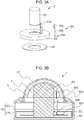
- Fig. 3A is an exploded perspective view of an image pickup unit 2 according to a first embodiment.
- Fig. 3B is an explanatory diagram for explaining an interior of the monitoring camera 1.
- the present embodiment deals with a monitoring camera included in an image monitoring system as an example.
- the image monitoring system is connected, for example, to a server (monitoring device) in an external image monitoring center so as to be able to wirelessly communicate with the server, and thus the image monitoring system monitors picked-up images on the server side.
- the monitoring camera described herein is not limited to one that is included in such an image monitoring system.
- the monitoring camera 1 of the present embodiment includes a housing 102, a dome cover 101, an image pickup unit 2, and a wireless communication means.
- the housing 102 includes a first housing 102a and a second housing 102b that support the dome cover 101.
- the first housing 102a and the second housing 102b are made of a metal material.
- a sealing material is disposed between the first housing 102a and the second housing 102b.
- a printed circuit board 207 is disposed inside the housing 102.
- the printed circuit board 207 includes, for example, a video processing engine, a communication processing engine, a memory, and a power supply IC.
- the printed circuit board 207 has external interfaces mounted thereon, such as an RJ45 connector, an external input/output connector, a power supply connector, an audio input/output connector, a video-out connector, and a connector for an external memory, such as an SD card.
- the dome cover 101 is a transparent member configured to protect a lens unit 201 (see Fig. 3B ) of the image pickup unit 2.
- the dome cover 101 is disposed on the front side (or adjacent to an object) in a photographing range of the lens unit 201.
- the dome cover 101 is substantially hemispherical and is made of resin, such as PC, or glass.
- a sealing material is disposed between the dome cover 101 and the housing 102a.
- the dome cover 101 and the housing 102 contains therein electric components, such as a heater, a microphone, a speaker, an LED, and a motor (which are not shown).
- the electric components are connected to one another, for example, by an electric cable, an FPC, or an FFC.
- the image pickup unit 2 includes the lens unit 201, a base 203, a support portion 203a, the wireless communication means 202, and the printed circuit board 207.
- the lens unit 201 includes a lens group, a lens holder, a printed circuit board, and an image pickup element (which are not shown) and is secured to the housing 102b, for example, with screws (not shown).
- the base 203 is a circular member having an opening in the center thereof for accommodating the lens unit 201.
- the base 203 is secured to the housing 102b, for example, with screws (not shown).
- the support portion 203a supports an antenna 202a.
- the support portion 203a is rectangular and protrudes from the base 203 toward the dome cover 101. One end of the support portion 203a is disposed inside the housing 102, whereas the other end of the support portion 203a is disposed inside the dome cover 101.
- the antenna 202a is disposed adjacent to the other end of the support portion 203a.
- the wireless communication means 202 is for transmitting and receiving data using a wireless communication technique, such as a wireless LAN.
- the wireless communication means 202 may be of a type where, as illustrated in Fig. 2A , a substrate 202c and the antenna 202a are configured as separate members, or may be of a type where, as illustrated in Fig. 2B , the substrate 202c and the antenna 202a are configured to form an integral unit.
- Fig. 2A illustrates the antenna 202a and the substrate 202c configured as separate members.
- the antenna 202a is electrically connected to the substrate 202c by a connection cable 202b.
- the substrate 202c has, for example, IC chips 202d, a metal sheet 202e, and a connector 202f, which are connected to the printed circuit board 207 and other components, for example, via connectors, screws, and PCI slots (which are not shown).
- Fig. 2B illustrates an antenna 202h and a substrate 202g configured to form an integral unit.
- the substrate 202g has, for example, IC chips 202i and a metal sheet 202j, which are connected to the printed circuit board 207 and other components, for example, via connectors, screws, and PCI slots (which are not shown).
- the antenna 202a is secured to the support portion 203a, for example, with screws.
- the antenna 202a is disposed away from components that interfere with wireless communication, such as the printed circuit board 207 that generates a lot of electrical noise and the housing 102 that is made of metal.
- the antenna 202a may be disposed at any position in a substantially hemispherical first space 3 (indicated by diagonal lines in Fig. 3B ) which is inside the dome cover 101. It is preferable, however, that the antenna 202a be disposed as close as possible to the dome cover 101.
- This configuration enables high-performance wireless communication, because the antenna 202a is disposed away from the printed circuit board 207 that generates a lot of electrical noise and the housing 102 that is made of metal.
- wireless communication means 202 of an antenna-substrate separate type is described as an example in the present embodiment, the wireless communication means 202 of an antenna-substrate integrated type, illustrated in Fig. 2B , may be used.
- the first embodiment has described an example where the lens unit 201 does not pan or tilt.
- a second embodiment will describe an antenna arrangement suitable for a monitoring camera (hereinafter referred to as PT monitoring camera) that is capable of panning and tilting.
- Fig. 4A is an exploded perspective view of the image pickup unit 2 according to the second embodiment.
- Fig. 4B is an explanatory diagram for explaining an interior of the monitoring camera 1 according to the second embodiment.
- Fig. 4C is an explanatory diagram for explaining an interior of the monitoring camera 1, with the lens unit 201 directed to the zenith.
- the image pickup unit 2 includes the lens unit 201, the wireless communication means 202, the main base 203, securing members 204 and 205, a pan base 206, and the printed circuit board 207.
- the main base 203 is disposed inside the housing 102b and secured to the housing 102b, for example, with screws (not shown).
- the main base 203 has a circular opening in the center thereof for accommodating the pan base 206.
- the pan base 206 supports the lens unit 201.
- the pan base 206 is supported in such a manner as to be rotatable about a pan rotation axis P in the pan direction, with respect to the main base 203.
- the pan base includes a ring portion 206 and a pair of support portions 206b protruding from the ring portion 206 toward a zenith portion of the dome cover 101.
- the pan base 206 is rotatably secured to the main base 203, for example (not shown), by a securing structure using an elastic component, such as a wave washer or a metal sheet, or screws; an engaging structure using gears; or a structure that electronically controls rotation of the gears with a motor.
- an elastic component such as a wave washer or a metal sheet, or screws
- the lens unit 201 is secured to the pan base 206 in such a manner as to be rotatable about a tilt rotation axis T in the tilt direction.
- the structure for rotatably securing the lens unit 201 to the pan base 206 include a structure that exerts a retaining force using screws, a flat washer, or a spring washer; and a structure that exerts a retaining force with an elastic member sandwiched between the lens unit 201 and the pan base 206.
- the securing member 205 secures the pan base 206 to the main base 203 in such a manner that the pan base 206 is rotatable in the pan direction.
- the antenna 202a is disposed in the substantially hemispherical first space 3 (indicated by diagonal lines in Fig. 4B and Fig. 4C ) inside the dome cover 101, closer to the zenith of the dome cover 101 than the center of rotation in the tilt direction is (i.e., the antenna 202a is disposed opposite the housing 102 with respect to the center of rotation in the tilt direction).
- the antenna 202a is secured to one of the support portions 206b, for example, with screws (not shown).
- This configuration of the PT monitoring camera also enables high-performance wireless communication, because the antenna 202a is disposed away from the printed circuit board 207 that generates a lot of electrical noise and the housing 102 that is made of metal.
- the lens unit 201 can be prevented from interfering with the antenna 202 during tilt rotation.
- a third embodiment differs from the second embodiment in the position of the antenna 202a and the size of the support portions 206.
- the other configurations of the third embodiment are the same as those of the second embodiment and their description will be omitted.
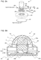
- Fig. 5A is an exploded perspective view of the image pickup unit 2 according to the third embodiment.
- Fig. 5B is an explanatory diagram for explaining an interior of the monitoring camera 1 according to the third embodiment.
- Fig. 5C is an explanatory diagram for explaining an interior of the monitoring camera 1, with the lens unit 201 directed to the zenith.
- Fig. 5D is a diagram for explaining an interior of the monitoring camera 1, with the lens unit 201 rotated in the tilt direction.
- the antenna 202a is secured to a side of the lens unit 201 adjacent to one of the support portions 206b. This means that the position of the antenna 202a with respect to the housing 102 changes as the lens unit 201 rotates in the tilt direction. Specifically, the antenna 202a is farthest from the housing 102 when the lens unit 201 is directed to the zenith, and becomes closer to the housing 102 as the lens unit 201 tilts.
- the antenna 202a is configured to be positioned inside the first space 3 indicated by diagonal lines, regardless of the position of the lens unit 201.
- This configuration of the PT monitoring camera also enables high-performance wireless communication, because the antenna 202a is disposed away from the printed circuit board 207 that generates a lot of electrical noise and the housing 102 that is made of metal.
- securing the antenna 202a to the lens unit 201 eliminates the need for components that support the antenna 202a and this can reduce the size of the monitoring camera 1.
- FIG. 6A is an exploded perspective view of the image pickup unit 2 according to the fourth embodiment.
- Fig. 6B is an explanatory diagram for explaining an interior of the monitoring camera 1 according to the fourth embodiment.
- Fig. 6C is an explanatory diagram for explaining an interior of the monitoring camera 1, with the lens unit 201 rotated in the tilt direction.
- Fig. 6D illustrates a comparative example of the monitoring camera 1, with the lens unit 201 tilted.
- the antenna 202a is secured to the periphery of the lens unit 201.
- the antenna 202a is configured to be positioned inside the first space 3 indicated by diagonal lines, regardless of the position of the lens unit 201.
- the monitoring camera 1 includes the restricting means that restricts rotation of the lens unit 201 in the tilt direction.
- the restricting means includes protrusions 301 disposed on the lens unit 201, and guides 300 provided in the respective support portions 206b of the pan base 206 to guide the respective protrusions 301.
- the protrusions 301 are configured to hit the corresponding ends of the respective guides 300 to restrict the rotation of the lens unit 201.
- the restricting means restricts the rotation of the lens unit 201 in such a manner that when the lens unit 201 rotates in the tilt direction, at least part of the antenna 202a is positioned in the first space 3 of the dome cover 101.
- the restricting means is configured to allow the lens unit 201 to move only in the direction in which the antenna 202a becomes closer to the object (see Fig. 6C ), and is configured not to allow the lens unit 201 to move in the direction in which the antenna 202a becomes farther from the object (see Fig. 6D ).
- This configuration of the PT monitoring camera also enables high-performance wireless communication, because the antenna 202a is disposed away from the printed circuit board 207 that generates a lot of electrical noise and the housing 102 that is made of metal.
- the restricting means restricts the rotation in the tilt direction to only one direction. This prevents the antenna 202a from moving in the direction away from the object, and enables higher-performance wireless communication.
- a fifth embodiment describes an example in which the housing 102 contains therein an inner cover 208.
- the configurations of the fifth embodiment are the same as those of the second embodiment, except the inner cover 208 and components therearound, and their description will be omitted.
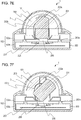
- Fig. 7A is an exploded perspective view of the image pickup unit 2 according to the fifth embodiment.
- Fig. 7B is an explanatory diagram for explaining an interior of the monitoring camera 1 according to the fifth embodiment.
- Fig. 7C and Fig. 7D are explanatory diagrams for explaining how the inner cover 208 of the fifth embodiment is secured in place.
- the image pickup unit 2 includes the inner cover 208, elastic members 209, support portions 210 extending from the respective support portions 206b, elastic members 211, securing members 212, and securing portions 213 extending from the respective support portions 206b.
- the inner cover 208 is secured to the support member 206 by hole portions 208b, the elastic members 209, and the securing members 212 in such a manner as to be biased toward the object.
- the inner cover 208 is secured to the support member 206 by the securing portions 213, the elastic members 211, and the securing members 212 in such a manner as to be biased in the direction of the tilt rotation axis.
- the dome cover 101 If the dome cover 101 is subjected to an external shock, the dome cover 101 is deformed inwardly and brought into contact with an upper end of the inner cover 208 before being brought into contact with the lens unit 201.
- the inner cover 208 When brought into contact with the dome cover 101, the inner cover 208, which is biased and held by the elastic members 209 and 211, is moved opposite the object.
- the inner cover 208 is configured to protect the lens unit 201 from an external shock.
- the antenna 202a is disposed in the substantially hemispherical first space 3 inside the dome cover 101, closer to the zenith of the dome cover 101 than the center of rotation in the tilt direction is (i.e., the antenna 202a is disposed opposite the housing 102 with respect to the center of rotation in the tilt direction).
- the antenna 202a is secured to a support portion 208a of the inner cover 208, for example, with screws (not shown).
- Fig. 7E is an explanatory diagram for explaining an interior of the monitoring camera 1, with the lens unit 201 directed to the zenith.
- Fig. 7F is an explanatory diagram for explaining an interior of the monitoring camera 1, with the lens unit 201 tilted.
- the antenna 202a on the inner cover 208 is positioned inside the first space 3, regardless of the position of the lens unit 201 and regardless of the pan motion of the support member 206.
- This configuration allows the antenna 202a to be positioned closer to the zenith than in the second embodiment and enables higher-performance wireless communication.
- a sixth embodiment describes an example where a light-shielding member 5 is mounted when the monitoring camera 1 is installed on a wall.
- the monitoring camera 1 may be installed on an outdoor wall and exposed to direct sunlight.
- the resulting rise in temperature inside the housing 102 may cause the monitoring camera 1 to malfunction. Additionally, if the lens unit 201 is exposed to direct sunlight, the resulting damage to optical components may also cause the monitoring camera 1 to malfunction.
- the light-shielding member 5 is generally attached to the monitoring camera 1.
- a metal material may be employed to form the light-shielding member 5.
- the monitoring camera 1 is covered with metal in this case. Since this interrupts transmission of radio waves from the antenna 202a to external devices, the quality of communication may be degraded.
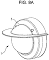
- Fig. 8A is an external view of the monitoring camera 1 having the light-shielding member 5 mounted thereon according to the sixth embodiment.
- Fig. 8B is an exploded perspective view of the monitoring camera 1 and the light-shielding member 5 according to the sixth embodiment.
- Fig. 8C and Fig. 8D are explanatory diagrams each illustrating a relation between the monitoring camera 1 and the light-shielding member 5 according to the sixth embodiment.
- the light-shielding member 5 is attached to the monitoring camera 1 of the third embodiment here, the same applies to the first, second, fourth, and fifth embodiments and their description will be omitted.
- the light-shielding member 5 is secured to the housing 102a with securing means, such as screws 6.
- the light-shielding member 5 is shaped to cover substantially the entire upper side of the monitoring camera 1 when the monitoring camera 1 is installed on a wall.
- the antenna 202a is not covered with the light-shielding member 5 made of metal and is disposed in a second space 7 (indicated by diagonal lines in Fig. 8C and Fig. 8D ) closer to the object than the metal housing 102 is.
- This configuration where the antenna 202a is disposed in the second space 7, enables high-performance wireless communication consistently even during the pan motion or tilt motion of the lens unit 201.
Landscapes
- Engineering & Computer Science (AREA)
- Multimedia (AREA)
- Signal Processing (AREA)
- Physics & Mathematics (AREA)
- General Physics & Mathematics (AREA)
- Studio Devices (AREA)
- Camera Bodies And Camera Details Or Accessories (AREA)
- Accessories Of Cameras (AREA)
Abstract
Description
- The present invention relates to an image pickup apparatus, such as a network camera, that includes a wireless communication means.
- Conventionally, in network cameras, a connection between the camera and a recording device has generally been a wired connection using, for example, a LAN cable. The wired connection requires wiring to the recording device and installation work associated with the wiring. This is a burden in building a monitoring system. In recent years, there has been a growing need for network cameras that are capable of connecting via wireless communication.
- Network cameras often have metal exteriors so as not to be broken by external shock. The presence of metal may interfere with wireless communication using wireless communication means. Therefore, it may be difficult for a network camera having a metal exterior to achieve high communication quality.
- Accordingly, for example, a radio antenna of a digital camera having a metal exterior may be disposed outside a housing (metal exterior) and covered with a resin having high radio-wave permeability (see Japanese Patent Laid-Open No.
2007-060237 - However, the configuration disclosed in Japanese Patent Laid-Open No.
2007-060237 - An object of embodiments described herein is to provide an image pickup apparatus that can achieve high-performance wireless communication with a simple configuration.
- An image pickup apparatus according to the present invention includes a lens unit, a dome cover made of resin or glass and having a substantially hemispherical first space covering the lens unit, a housing configured to support the dome cover, and an antenna capable of wirelessly communicating with external devices. The antenna is disposed in the first space of the dome cover.
-
- [
Fig. 1A] Fig. 1A presents an external view and an exploded perspective view of a network monitoring camera according to a first embodiment of the present invention. - [
Fig. 1B] Fig. 1B presents an external view and an exploded perspective view of the network monitoring camera according to the first embodiment of the present invention. - [
Fig. 2A] Fig. 2A is a schematic diagram of a wireless communication means according to an embodiment of the present invention. - [
Fig. 2B] Fig. 2B is a schematic diagram of another wireless communication means according to the embodiment of the present invention. - [
Fig. 3A] Fig. 3A presents an exploded perspective view of animage pickup unit 2 and an explanatory diagram for explaining an interior of the network monitoring camera according to the first embodiment. - [
Fig. 3B] Fig. 3B presents an exploded perspective view of theimage pickup unit 2 and an explanatory diagram for explaining an interior of the network monitoring camera according to the first embodiment. - [
Fig. 4A] Fig. 4A presents an exploded perspective view of theimage pickup unit 2 and an explanatory diagram for explaining an interior of a network monitoring camera according to a second embodiment. - [
Fig. 4B] Fig. 4B presents an exploded perspective view of theimage pickup unit 2 and an explanatory diagram for explaining an interior of the network monitoring camera according to the second embodiment. - [
Fig. 4C] Fig. 4C presents an exploded perspective view of theimage pickup unit 2 and an explanatory diagram for explaining an interior of the network monitoring camera according to the second embodiment. - [
Fig. 5A] Fig. 5A presents an exploded perspective view of theimage pickup unit 2 and an explanatory diagram for explaining an interior of a network monitoring camera according to a third embodiment. - [
Fig. 5B] Fig. 5B presents an exploded perspective view of theimage pickup unit 2 and an explanatory diagram for explaining an interior of the network monitoring camera according to the third embodiment. - [
Fig. 5C] Fig. 5C is an explanatory diagram for explaining an interior of the network monitoring camera of theimage pickup unit 2 according to the third embodiment. - [
Fig. 5D] Fig. 5D is an explanatory diagram for explaining an interior of the network monitoring camera of theimage pickup unit 2 according to the third embodiment. - [
Fig. 6A] Fig. 6A presents an exploded perspective view of theimage pickup unit 2 and an explanatory diagram for explaining an interior of a network monitoring camera according to a fourth embodiment. - [
Fig. 6B] Fig. 6B presents an exploded perspective view of theimage pickup unit 2 and an explanatory diagram for explaining an interior of the network monitoring camera according to the fourth embodiment. - [
Fig. 6C] Fig. 6C is an explanatory diagram for explaining an interior of the network monitoring camera of theimage pickup unit 2 according to the fourth embodiment. - [
Fig. 6D] Fig. 6D is an explanatory diagram for explaining an interior of the network monitoring camera of theimage pickup unit 2 according to the fourth embodiment. - [
Fig. 7A] Fig. 7A presents an exploded perspective view of theimage pickup unit 2 and an explanatory diagram for explaining an interior of a network monitoring camera according to a fifth embodiment. - [
Fig. 7B] Fig. 7B is an explanatory diagram for explaining an interior of the network monitoring camera of theimage pickup unit 2 according to the fifth embodiment. - [
Fig. 7C] Fig. 7C is an explanatory diagram for explaining an interior of the network monitoring camera of theimage pickup unit 2 according to the fifth embodiment. - [
Fig. 7D] Fig. 7D is an explanatory diagram for explaining an interior of the network monitoring camera of theimage pickup unit 2 according to the fifth embodiment. - [
Fig. 7E] Fig. 7E is an explanatory diagram for explaining an interior of the network monitoring camera of theimage pickup unit 2 according to the fifth embodiment. - [
Fig. 7F] Fig. 7F is an explanatory diagram for explaining an interior of the network monitoring camera of theimage pickup unit 2 according to the fifth embodiment. - [
Fig. 8A] Fig. 8A presents an external view of a network monitoring camera and an explanatory diagram for explaining an interior of the network monitoring camera according to a sixth embodiment. - [
Fig. 8B] Fig. 8B presents an external view of the network monitoring camera and an explanatory diagram for explaining an interior of the network monitoring camera according to the sixth embodiment. - [
Fig. 8C] Fig. 8C is an explanatory diagram for explaining an interior of the network monitoring camera of theimage pickup unit 2 according to the sixth embodiment. - [
Fig. 8D] Fig. 8D is an explanatory diagram for explaining an interior of the network monitoring camera of theimage pickup unit 2 according to the sixth embodiment. - An exemplary embodiment of the present invention will now be described with reference to the drawings.
Fig. 1A is an external view of a network monitoring camera 1 (hereinafter referred to as monitoring camera) according to the embodiment of the present invention.Fig. 1B is an exploded perspective view of the monitoring camera illustrated inFig. 1A .Fig. 2A is a schematic diagram of a wireless communication means of an antenna-substrate separate type.Fig. 2B is a schematic diagram of a wireless communication means of an antenna-substrate integrated type.Fig. 3A is an exploded perspective view of animage pickup unit 2 according to a first embodiment.Fig. 3B is an explanatory diagram for explaining an interior of themonitoring camera 1. - The present embodiment deals with a monitoring camera included in an image monitoring system as an example. Specifically, the image monitoring system is connected, for example, to a server (monitoring device) in an external image monitoring center so as to be able to wirelessly communicate with the server, and thus the image monitoring system monitors picked-up images on the server side. However, the monitoring camera described herein is not limited to one that is included in such an image monitoring system.
- As illustrated in
Fig. 1 , themonitoring camera 1 of the present embodiment includes ahousing 102, adome cover 101, animage pickup unit 2, and a wireless communication means. - The
housing 102 includes afirst housing 102a and asecond housing 102b that support thedome cover 101. Thefirst housing 102a and thesecond housing 102b are made of a metal material. A sealing material is disposed between thefirst housing 102a and thesecond housing 102b. A printedcircuit board 207 is disposed inside thehousing 102. The printedcircuit board 207 includes, for example, a video processing engine, a communication processing engine, a memory, and a power supply IC. The printedcircuit board 207 has external interfaces mounted thereon, such as an RJ45 connector, an external input/output connector, a power supply connector, an audio input/output connector, a video-out connector, and a connector for an external memory, such as an SD card. - The
dome cover 101 is a transparent member configured to protect a lens unit 201 (seeFig. 3B ) of theimage pickup unit 2. Thedome cover 101 is disposed on the front side (or adjacent to an object) in a photographing range of thelens unit 201. Thedome cover 101 is substantially hemispherical and is made of resin, such as PC, or glass. A sealing material is disposed between thedome cover 101 and thehousing 102a. - The
dome cover 101 and thehousing 102 contains therein electric components, such as a heater, a microphone, a speaker, an LED, and a motor (which are not shown). The electric components are connected to one another, for example, by an electric cable, an FPC, or an FFC. - As illustrated in
Fig. 3A , theimage pickup unit 2 includes thelens unit 201, abase 203, asupport portion 203a, the wireless communication means 202, and the printedcircuit board 207. Thelens unit 201 includes a lens group, a lens holder, a printed circuit board, and an image pickup element (which are not shown) and is secured to thehousing 102b, for example, with screws (not shown). Thebase 203 is a circular member having an opening in the center thereof for accommodating thelens unit 201. Thebase 203 is secured to thehousing 102b, for example, with screws (not shown). Thesupport portion 203a supports anantenna 202a. Thesupport portion 203a is rectangular and protrudes from the base 203 toward thedome cover 101. One end of thesupport portion 203a is disposed inside thehousing 102, whereas the other end of thesupport portion 203a is disposed inside thedome cover 101. Theantenna 202a is disposed adjacent to the other end of thesupport portion 203a. - The wireless communication means 202 is for transmitting and receiving data using a wireless communication technique, such as a wireless LAN. The wireless communication means 202 may be of a type where, as illustrated in
Fig. 2A , asubstrate 202c and theantenna 202a are configured as separate members, or may be of a type where, as illustrated inFig. 2B , thesubstrate 202c and theantenna 202a are configured to form an integral unit. -
Fig. 2A illustrates theantenna 202a and thesubstrate 202c configured as separate members. Theantenna 202a is electrically connected to thesubstrate 202c by aconnection cable 202b. - The
substrate 202c has, for example,IC chips 202d, ametal sheet 202e, and aconnector 202f, which are connected to the printedcircuit board 207 and other components, for example, via connectors, screws, and PCI slots (which are not shown). -
Fig. 2B illustrates anantenna 202h and asubstrate 202g configured to form an integral unit. - The
substrate 202g has, for example,IC chips 202i and ametal sheet 202j, which are connected to the printedcircuit board 207 and other components, for example, via connectors, screws, and PCI slots (which are not shown). - The
antenna 202a is secured to thesupport portion 203a, for example, with screws. Theantenna 202a is disposed away from components that interfere with wireless communication, such as the printedcircuit board 207 that generates a lot of electrical noise and thehousing 102 that is made of metal. Theantenna 202a may be disposed at any position in a substantially hemispherical first space 3 (indicated by diagonal lines inFig. 3B ) which is inside thedome cover 101. It is preferable, however, that theantenna 202a be disposed as close as possible to thedome cover 101. - This configuration enables high-performance wireless communication, because the
antenna 202a is disposed away from the printedcircuit board 207 that generates a lot of electrical noise and thehousing 102 that is made of metal. - Although the wireless communication means 202 of an antenna-substrate separate type is described as an example in the present embodiment, the wireless communication means 202 of an antenna-substrate integrated type, illustrated in
Fig. 2B , may be used. - The first embodiment has described an example where the
lens unit 201 does not pan or tilt. A second embodiment will describe an antenna arrangement suitable for a monitoring camera (hereinafter referred to as PT monitoring camera) that is capable of panning and tilting.Fig. 4A is an exploded perspective view of theimage pickup unit 2 according to the second embodiment.Fig. 4B is an explanatory diagram for explaining an interior of themonitoring camera 1 according to the second embodiment.Fig. 4C is an explanatory diagram for explaining an interior of themonitoring camera 1, with thelens unit 201 directed to the zenith. - As illustrated in
Fig. 4A , theimage pickup unit 2 according to the second embodiment includes thelens unit 201, the wireless communication means 202, themain base 203, securingmembers pan base 206, and the printedcircuit board 207. - The
main base 203 is disposed inside thehousing 102b and secured to thehousing 102b, for example, with screws (not shown). Themain base 203 has a circular opening in the center thereof for accommodating thepan base 206. - The
pan base 206 supports thelens unit 201. Thepan base 206 is supported in such a manner as to be rotatable about a pan rotation axis P in the pan direction, with respect to themain base 203. The pan base includes aring portion 206 and a pair ofsupport portions 206b protruding from thering portion 206 toward a zenith portion of thedome cover 101. - The
pan base 206 is rotatably secured to themain base 203, for example (not shown), by a securing structure using an elastic component, such as a wave washer or a metal sheet, or screws; an engaging structure using gears; or a structure that electronically controls rotation of the gears with a motor. - With the securing
members 204, thelens unit 201 is secured to thepan base 206 in such a manner as to be rotatable about a tilt rotation axis T in the tilt direction. Examples of the structure for rotatably securing thelens unit 201 to thepan base 206 include a structure that exerts a retaining force using screws, a flat washer, or a spring washer; and a structure that exerts a retaining force with an elastic member sandwiched between thelens unit 201 and thepan base 206. - The securing
member 205 secures thepan base 206 to themain base 203 in such a manner that thepan base 206 is rotatable in the pan direction. - The
antenna 202a is disposed in the substantially hemispherical first space 3 (indicated by diagonal lines inFig. 4B and Fig. 4C ) inside thedome cover 101, closer to the zenith of thedome cover 101 than the center of rotation in the tilt direction is (i.e., theantenna 202a is disposed opposite thehousing 102 with respect to the center of rotation in the tilt direction). Theantenna 202a is secured to one of thesupport portions 206b, for example, with screws (not shown). - This configuration of the PT monitoring camera also enables high-performance wireless communication, because the
antenna 202a is disposed away from the printedcircuit board 207 that generates a lot of electrical noise and thehousing 102 that is made of metal. - Since the
antenna 202a is disposed on thepan base 206, thelens unit 201 can be prevented from interfering with theantenna 202 during tilt rotation. - A third embodiment differs from the second embodiment in the position of the
antenna 202a and the size of thesupport portions 206. The other configurations of the third embodiment are the same as those of the second embodiment and their description will be omitted.Fig. 5A is an exploded perspective view of theimage pickup unit 2 according to the third embodiment.Fig. 5B is an explanatory diagram for explaining an interior of themonitoring camera 1 according to the third embodiment.Fig. 5C is an explanatory diagram for explaining an interior of themonitoring camera 1, with thelens unit 201 directed to the zenith.Fig. 5D is a diagram for explaining an interior of themonitoring camera 1, with thelens unit 201 rotated in the tilt direction. - In the third embodiment, the
antenna 202a is secured to a side of thelens unit 201 adjacent to one of thesupport portions 206b. This means that the position of theantenna 202a with respect to thehousing 102 changes as thelens unit 201 rotates in the tilt direction. Specifically, theantenna 202a is farthest from thehousing 102 when thelens unit 201 is directed to the zenith, and becomes closer to thehousing 102 as thelens unit 201 tilts. Theantenna 202a is configured to be positioned inside thefirst space 3 indicated by diagonal lines, regardless of the position of thelens unit 201. - This configuration of the PT monitoring camera also enables high-performance wireless communication, because the
antenna 202a is disposed away from the printedcircuit board 207 that generates a lot of electrical noise and thehousing 102 that is made of metal. - Additionally, securing the
antenna 202a to thelens unit 201 eliminates the need for components that support theantenna 202a and this can reduce the size of themonitoring camera 1. - The second embodiment and the third embodiment have dealt with examples where the
lens unit 201 is capable of tilting and rotating about ±90° on both sides (with the zenith being a tilt angle of 0°). A fourth embodiment describes an example where thelens unit 201 is capable of tilting and rotating about 90° on one side. The fourth embodiment differs from the third embodiment in the position of theantenna 202a and in having a restricting means. The other configurations of the fourth embodiment are the same as those of the third embodiment and their description will be omitted.Fig. 6A is an exploded perspective view of theimage pickup unit 2 according to the fourth embodiment.Fig. 6B is an explanatory diagram for explaining an interior of themonitoring camera 1 according to the fourth embodiment.Fig. 6C is an explanatory diagram for explaining an interior of themonitoring camera 1, with thelens unit 201 rotated in the tilt direction.Fig. 6D illustrates a comparative example of themonitoring camera 1, with thelens unit 201 tilted. - In the fourth embodiment, the
antenna 202a is secured to the periphery of thelens unit 201. Theantenna 202a is configured to be positioned inside thefirst space 3 indicated by diagonal lines, regardless of the position of thelens unit 201. - The
monitoring camera 1 according to the fourth embodiment includes the restricting means that restricts rotation of thelens unit 201 in the tilt direction. - The restricting means includes
protrusions 301 disposed on thelens unit 201, and guides 300 provided in therespective support portions 206b of thepan base 206 to guide therespective protrusions 301. Theprotrusions 301 are configured to hit the corresponding ends of therespective guides 300 to restrict the rotation of thelens unit 201. The restricting means restricts the rotation of thelens unit 201 in such a manner that when thelens unit 201 rotates in the tilt direction, at least part of theantenna 202a is positioned in thefirst space 3 of thedome cover 101. The restricting means is configured to allow thelens unit 201 to move only in the direction in which theantenna 202a becomes closer to the object (seeFig. 6C ), and is configured not to allow thelens unit 201 to move in the direction in which theantenna 202a becomes farther from the object (seeFig. 6D ). - This configuration of the PT monitoring camera also enables high-performance wireless communication, because the
antenna 202a is disposed away from the printedcircuit board 207 that generates a lot of electrical noise and thehousing 102 that is made of metal. - Additionally, the restricting means restricts the rotation in the tilt direction to only one direction. This prevents the
antenna 202a from moving in the direction away from the object, and enables higher-performance wireless communication. - A fifth embodiment describes an example in which the
housing 102 contains therein aninner cover 208. - The configurations of the fifth embodiment are the same as those of the second embodiment, except the
inner cover 208 and components therearound, and their description will be omitted. -
Fig. 7A is an exploded perspective view of theimage pickup unit 2 according to the fifth embodiment. -
Fig. 7B is an explanatory diagram for explaining an interior of themonitoring camera 1 according to the fifth embodiment. -
Fig. 7C andFig. 7D are explanatory diagrams for explaining how theinner cover 208 of the fifth embodiment is secured in place. - As illustrated in
Fig. 7A to Fig. 7D , theimage pickup unit 2 according to the fifth embodiment includes theinner cover 208,elastic members 209,support portions 210 extending from therespective support portions 206b,elastic members 211, securingmembers 212, and securingportions 213 extending from therespective support portions 206b. - The
inner cover 208 is secured to thesupport member 206 byhole portions 208b, theelastic members 209, and the securingmembers 212 in such a manner as to be biased toward the object. - At the same time, the
inner cover 208 is secured to thesupport member 206 by the securingportions 213, theelastic members 211, and the securingmembers 212 in such a manner as to be biased in the direction of the tilt rotation axis. - This enables the
inner cover 208 to rotate in conjunction with the pan motion of thesupport member 206. - If the
dome cover 101 is subjected to an external shock, thedome cover 101 is deformed inwardly and brought into contact with an upper end of theinner cover 208 before being brought into contact with thelens unit 201. - When brought into contact with the
dome cover 101, theinner cover 208, which is biased and held by theelastic members - This brings a
lower end portion 208c of theinner cover 208 into contact with the raisedportion 203a of thebase 206. - As described above, the
inner cover 208 is configured to protect thelens unit 201 from an external shock. Theantenna 202a is disposed in the substantially hemisphericalfirst space 3 inside thedome cover 101, closer to the zenith of thedome cover 101 than the center of rotation in the tilt direction is (i.e., theantenna 202a is disposed opposite thehousing 102 with respect to the center of rotation in the tilt direction). Theantenna 202a is secured to asupport portion 208a of theinner cover 208, for example, with screws (not shown). -
Fig. 7E is an explanatory diagram for explaining an interior of themonitoring camera 1, with thelens unit 201 directed to the zenith. -
Fig. 7F is an explanatory diagram for explaining an interior of themonitoring camera 1, with thelens unit 201 tilted. - As illustrated in
Fig. 7E and Fig. 7F , theantenna 202a on theinner cover 208 is positioned inside thefirst space 3, regardless of the position of thelens unit 201 and regardless of the pan motion of thesupport member 206. - This configuration allows the
antenna 202a to be positioned closer to the zenith than in the second embodiment and enables higher-performance wireless communication. - A sixth embodiment describes an example where a light-shielding
member 5 is mounted when themonitoring camera 1 is installed on a wall. - The
monitoring camera 1 may be installed on an outdoor wall and exposed to direct sunlight. - When the
monitoring camera 1 is exposed to direct sunlight, the resulting rise in temperature inside thehousing 102 may cause themonitoring camera 1 to malfunction. Additionally, if thelens unit 201 is exposed to direct sunlight, the resulting damage to optical components may also cause themonitoring camera 1 to malfunction. - Accordingly, when the
monitoring camera 1 is installed in a place exposed to direct sunlight, the light-shieldingmember 5 is generally attached to themonitoring camera 1. - For example, to ensure resistance to shock and corrosion outdoors, a metal material may be employed to form the light-shielding
member 5. However, themonitoring camera 1 is covered with metal in this case. Since this interrupts transmission of radio waves from theantenna 202a to external devices, the quality of communication may be degraded. - Accordingly, a preferable relation between the
antenna 202a and the light-shieldingmember 5 will be described. -
Fig. 8A is an external view of themonitoring camera 1 having the light-shieldingmember 5 mounted thereon according to the sixth embodiment. -
Fig. 8B is an exploded perspective view of themonitoring camera 1 and the light-shieldingmember 5 according to the sixth embodiment. -
Fig. 8C and Fig. 8D are explanatory diagrams each illustrating a relation between the monitoringcamera 1 and the light-shieldingmember 5 according to the sixth embodiment. - Although the light-shielding
member 5 is attached to themonitoring camera 1 of the third embodiment here, the same applies to the first, second, fourth, and fifth embodiments and their description will be omitted. - The light-shielding
member 5 is secured to thehousing 102a with securing means, such as screws 6. - The light-shielding
member 5 is shaped to cover substantially the entire upper side of themonitoring camera 1 when themonitoring camera 1 is installed on a wall. - This can protect the
dome cover 101, thehousing 102, and thelens unit 201 from exposure to direct sunlight. - The
antenna 202a is not covered with the light-shieldingmember 5 made of metal and is disposed in a second space 7 (indicated by diagonal lines inFig. 8C and Fig. 8D ) closer to the object than themetal housing 102 is. - This configuration, where the
antenna 202a is disposed in thesecond space 7, enables high-performance wireless communication consistently even during the pan motion or tilt motion of thelens unit 201. - The configurations of the present invention are not limited to those illustrated in the embodiments and, for example, the materials, shapes, dimensions, forms, numbers, and positions described above may be changed as appropriate within the scope of the present invention.
- The present invention is not limited to the embodiments described above, and various changes and modifications may be made thereto without departing from the spirit and scope of the present invention. The following claims are attached to make public the scope of the present invention.
- This application claims priority based on Japanese Patent Application No.
2017-107450 filed May 31, 2017
Claims (13)
- An image pickup apparatus comprising:a lens unit;a dome cover made of resin or glass and having a substantially hemispherical first space covering the lens unit;a housing configured to support the dome cover; andan antenna capable of wirelessly communicating with external devices,wherein the antenna is disposed in the first space of the dome cover.
- The image pickup apparatus according to Claim 1, further comprising:a support portion configured to support the antenna; anda base disposed inside the housing,wherein the support portion protrudes from the base toward the dome cover.
- The image pickup apparatus according to Claim 2, wherein a substrate is disposed inside the housing;
one end of the support portion is disposed inside the housing;
the other end of the support portion is disposed in the first space of the dome cover; and
the antenna is disposed at the other end of the support portion. - The image pickup apparatus according to Claim 2, wherein the support portion is rectangular.
- The image pickup apparatus according to Claim 1, further comprising:a pan base configured to support the lens unit in such a manner as to allow the lens unit to rotate in a tilt direction; anda main base disposed inside the housing and configured to support the pan base in such a manner as to allow the pan base to rotate with respect to the housing in a pan direction,wherein the antenna is disposed on the pan base.
- The image pickup apparatus according to Claim 5, wherein the antenna is disposed opposite the housing with respect to a center of rotation in the tilt direction.
- The image pickup apparatus according to Claim 1, wherein the antenna is disposed on a periphery of the lens unit.
- The image pickup apparatus according to Claim 1, further comprising restricting means for restricting rotation of the lens unit in a tilt direction,
wherein the restricting means restricts rotation of the lens unit in such a manner that when the lens unit rotates in the tilt direction, at least part of the antenna is positioned in the first space of the dome cover. - The image pickup apparatus according to Claim 1, further comprising an inner cover disposed inside the housing,
wherein the inner cover is supported by the pan base, and the antenna is secured to the inner cover. - The image pickup apparatus according to Claim 9, wherein the inner cover is biased to the pan base by an elastic member.
- The image pickup apparatus according to Claim 1, wherein the housing is made of a metal material.
- The image pickup apparatus according to Claim 1, further comprising a light-shielding member attached to an outer side of the housing in such a manner as to cover the dome cover and the housing, and the antenna is disposed so as not to be covered by the light-shielding member.
- The image pickup apparatus according to Claim 12, wherein the light-shielding member is made of a metal material.
Applications Claiming Priority (2)
| Application Number | Priority Date | Filing Date | Title |
|---|---|---|---|
| JP2017107450 | 2017-05-31 | ||
| PCT/JP2018/020029 WO2018221377A1 (en) | 2017-05-31 | 2018-05-24 | Imaging device |
Publications (2)
| Publication Number | Publication Date |
|---|---|
| EP3633449A1 true EP3633449A1 (en) | 2020-04-08 |
| EP3633449A4 EP3633449A4 (en) | 2021-03-03 |
Family
ID=64456258
Family Applications (1)
| Application Number | Title | Priority Date | Filing Date |
|---|---|---|---|
| EP18810394.9A Withdrawn EP3633449A4 (en) | 2017-05-31 | 2018-05-24 | Imaging device |
Country Status (4)
| Country | Link |
|---|---|
| US (1) | US10939021B2 (en) |
| EP (1) | EP3633449A4 (en) |
| JP (1) | JP7046655B2 (en) |
| WO (1) | WO2018221377A1 (en) |
Families Citing this family (9)
| Publication number | Priority date | Publication date | Assignee | Title |
|---|---|---|---|---|
| JP7046655B2 (en) * | 2017-05-31 | 2022-04-04 | キヤノン株式会社 | Imaging device |
| US11297212B2 (en) * | 2018-04-05 | 2022-04-05 | Canon Kabushiki Kaisha | Imaging apparatus |
| JP7046683B2 (en) * | 2018-04-05 | 2022-04-04 | キヤノン株式会社 | Imaging device |
| JP7401197B2 (en) * | 2019-05-29 | 2023-12-19 | キヤノン株式会社 | Imaging device |
| JP7446832B2 (en) | 2020-01-30 | 2024-03-11 | キヤノン株式会社 | Imaging device |
| KR20210112792A (en) * | 2020-03-06 | 2021-09-15 | 한화테크윈 주식회사 | Pan motion camera blocking irregular reflection of illumination light |
| CN112637456B (en) * | 2020-12-09 | 2022-11-04 | 杭州海康威视数字技术股份有限公司 | A camera with built-in antenna assembly |
| CN113193329B (en) * | 2021-04-08 | 2023-07-25 | 杭州海康威视数字技术股份有限公司 | Camera and antenna module |
| CN113381181A (en) * | 2021-06-01 | 2021-09-10 | 杭州海康威视数字技术股份有限公司 | Video camera |
Family Cites Families (24)
| Publication number | Priority date | Publication date | Assignee | Title |
|---|---|---|---|---|
| JPH08265867A (en) * | 1995-03-27 | 1996-10-11 | Shin Caterpillar Mitsubishi Ltd | Communication equipment |
| US6951536B2 (en) * | 2001-07-30 | 2005-10-04 | Olympus Corporation | Capsule-type medical device and medical system |
| JP4762627B2 (en) * | 2005-07-25 | 2011-08-31 | オリンパス株式会社 | Imaging apparatus and manufacturing method of imaging apparatus |
| JP2007060237A (en) | 2005-08-24 | 2007-03-08 | Nikon Corp | Camera having wireless communication function |
| JP2007104255A (en) * | 2005-10-04 | 2007-04-19 | Konica Minolta Holdings Inc | Camera unit |
| JP4916726B2 (en) * | 2006-01-24 | 2012-04-18 | 株式会社日立国際電気 | Camera device |
| SE531510C2 (en) * | 2007-09-04 | 2009-05-05 | Tommy Forsell | blood Analysis |
| JP2012109687A (en) * | 2010-11-15 | 2012-06-07 | Canon Inc | Imaging apparatus |
| US9215429B2 (en) * | 2011-10-31 | 2015-12-15 | Rosco, Inc. | Mirror monitor using two levels of reflectivity |
| JP2014048511A (en) * | 2012-08-31 | 2014-03-17 | Fujifilm Corp | Monitor camera with dome cover |
| GB2508226B (en) * | 2012-11-26 | 2015-08-19 | Selex Es Ltd | Protective housing |
| JP6078317B2 (en) * | 2012-12-07 | 2017-02-08 | 株式会社トプコン | Omni-directional camera |
| JP2014236318A (en) * | 2013-05-31 | 2014-12-15 | キヤノン株式会社 | Imaging device |
| US20150062333A1 (en) * | 2013-08-30 | 2015-03-05 | David J. Kilner | Method and system for nature observation |
| JP6241783B2 (en) * | 2013-09-19 | 2017-12-06 | パナソニックIpマネジメント株式会社 | Imaging apparatus and imaging system |
| US9716798B2 (en) * | 2014-09-08 | 2017-07-25 | At&T Intellectual Property I, L.P. | ACR buffering in the cloud |
| US9729791B2 (en) * | 2014-10-31 | 2017-08-08 | Ubiquiti Networks, Inc. | Micro camera and multi-purpose mounting base |
| JP6217942B2 (en) * | 2015-03-23 | 2017-10-25 | パナソニックIpマネジメント株式会社 | Imaging device |
| JP6399991B2 (en) * | 2015-10-19 | 2018-10-03 | キヤノン株式会社 | Surveillance camera |
| JP2017107450A (en) | 2015-12-10 | 2017-06-15 | 富士通株式会社 | Access monitoring program, access monitoring method, and access monitoring apparatus |
| JP7046655B2 (en) * | 2017-05-31 | 2022-04-04 | キヤノン株式会社 | Imaging device |
| US10665073B1 (en) * | 2017-06-07 | 2020-05-26 | Lee C Richerson, Jr. | Floating pool monitor and alarm device |
| JP2019020557A (en) * | 2017-07-14 | 2019-02-07 | キヤノン株式会社 | Imaging apparatus |
| US10713811B2 (en) * | 2017-09-29 | 2020-07-14 | Sensormatic Electronics, LLC | Security camera system with multi-directional mount and method of operation |
-
2018
- 2018-03-08 JP JP2018042443A patent/JP7046655B2/en active Active
- 2018-05-24 EP EP18810394.9A patent/EP3633449A4/en not_active Withdrawn
- 2018-05-24 WO PCT/JP2018/020029 patent/WO2018221377A1/en not_active Ceased
-
2019
- 2019-11-12 US US16/681,637 patent/US10939021B2/en active Active
Also Published As
| Publication number | Publication date |
|---|---|
| WO2018221377A1 (en) | 2018-12-06 |
| US10939021B2 (en) | 2021-03-02 |
| US20200084347A1 (en) | 2020-03-12 |
| EP3633449A4 (en) | 2021-03-03 |
| JP7046655B2 (en) | 2022-04-04 |
| JP2018207476A (en) | 2018-12-27 |
Similar Documents
| Publication | Publication Date | Title |
|---|---|---|
| US10939021B2 (en) | Image pickup apparatus | |
| US20190098189A1 (en) | Image pickup apparatus | |
| KR101082808B1 (en) | Camera apparatus | |
| CN107370915B (en) | Image pickup apparatus such as web camera and image monitoring system | |
| US10057473B2 (en) | Circuit board device and image capturing module having the circuit board device | |
| CN105049694B (en) | Camera and terminal | |
| US11297212B2 (en) | Imaging apparatus | |
| WO2019228380A1 (en) | Camera module and mobile terminal | |
| WO2019228333A1 (en) | Camera module and mobile terminal | |
| CN112822383A (en) | Lens, camera module and electronic equipment | |
| CN111638638A (en) | Wrist-wearing device | |
| JP2014239394A (en) | Imaging apparatus | |
| KR100802236B1 (en) | Security camera | |
| EP3726828A1 (en) | Imaging device, imaging system, and recording medium | |
| CN110892703A (en) | camera | |
| CN118075583A (en) | Tripod head camera | |
| CN112526798B (en) | Variable field angle lens mechanism, adjustment method thereof, and electronic device | |
| CN110099197A (en) | CCD camera assembly and electronic equipment | |
| KR20180005468A (en) | Surveillance camera system | |
| CN214381094U (en) | Lens, camera module and electronic equipment | |
| KR101621887B1 (en) | Camera module | |
| JP7446832B2 (en) | Imaging device | |
| JP5619049B2 (en) | Imaging device | |
| JP2019148644A (en) | Imaging apparatus | |
| JP2016015661A (en) | Imaging device with wireless communication function |
Legal Events
| Date | Code | Title | Description |
|---|---|---|---|
| STAA | Information on the status of an ep patent application or granted ep patent |
Free format text: STATUS: THE INTERNATIONAL PUBLICATION HAS BEEN MADE |
|
| PUAI | Public reference made under article 153(3) epc to a published international application that has entered the european phase |
Free format text: ORIGINAL CODE: 0009012 |
|
| STAA | Information on the status of an ep patent application or granted ep patent |
Free format text: STATUS: REQUEST FOR EXAMINATION WAS MADE |
|
| 17P | Request for examination filed |
Effective date: 20200102 |
|
| AK | Designated contracting states |
Kind code of ref document: A1 Designated state(s): AL AT BE BG CH CY CZ DE DK EE ES FI FR GB GR HR HU IE IS IT LI LT LU LV MC MK MT NL NO PL PT RO RS SE SI SK SM TR |
|
| AX | Request for extension of the european patent |
Extension state: BA ME |
|
| DAV | Request for validation of the european patent (deleted) | ||
| DAX | Request for extension of the european patent (deleted) | ||
| A4 | Supplementary search report drawn up and despatched |
Effective date: 20210202 |
|
| RIC1 | Information provided on ipc code assigned before grant |
Ipc: G03B 17/02 20210101AFI20210127BHEP Ipc: G03B 37/02 20210101ALN20210127BHEP Ipc: H01Q 9/42 20060101ALN20210127BHEP Ipc: G08B 13/196 20060101ALI20210127BHEP Ipc: H04N 5/232 20060101ALI20210127BHEP Ipc: G03B 17/56 20210101ALI20210127BHEP Ipc: H04N 5/225 20060101ALI20210127BHEP Ipc: H04N 5/222 20060101ALI20210127BHEP |
|
| STAA | Information on the status of an ep patent application or granted ep patent |
Free format text: STATUS: EXAMINATION IS IN PROGRESS |
|
| 17Q | First examination report despatched |
Effective date: 20230628 |
|
| STAA | Information on the status of an ep patent application or granted ep patent |
Free format text: STATUS: THE APPLICATION HAS BEEN WITHDRAWN |
|
| 18W | Application withdrawn |
Effective date: 20231016 |