EP3633387A1 - Pitot tube heater assembly - Google Patents
Pitot tube heater assembly Download PDFInfo
- Publication number
- EP3633387A1 EP3633387A1 EP19201456.1A EP19201456A EP3633387A1 EP 3633387 A1 EP3633387 A1 EP 3633387A1 EP 19201456 A EP19201456 A EP 19201456A EP 3633387 A1 EP3633387 A1 EP 3633387A1
- Authority
- EP
- European Patent Office
- Prior art keywords
- tube
- sleeve
- pitot
- passage
- heating element
- Prior art date
- Legal status (The legal status is an assumption and is not a legal conclusion. Google has not performed a legal analysis and makes no representation as to the accuracy of the status listed.)
- Granted
Links
Images


Classifications
-
- H—ELECTRICITY
- H01—ELECTRIC ELEMENTS
- H01C—RESISTORS
- H01C17/00—Apparatus or processes specially adapted for manufacturing resistors
- H01C17/04—Apparatus or processes specially adapted for manufacturing resistors adapted for winding the resistive element
-
- F—MECHANICAL ENGINEERING; LIGHTING; HEATING; WEAPONS; BLASTING
- F16—ENGINEERING ELEMENTS AND UNITS; GENERAL MEASURES FOR PRODUCING AND MAINTAINING EFFECTIVE FUNCTIONING OF MACHINES OR INSTALLATIONS; THERMAL INSULATION IN GENERAL
- F16L—PIPES; JOINTS OR FITTINGS FOR PIPES; SUPPORTS FOR PIPES, CABLES OR PROTECTIVE TUBING; MEANS FOR THERMAL INSULATION IN GENERAL
- F16L33/00—Arrangements for connecting hoses to rigid members; Rigid hose-connectors, i.e. single members engaging both hoses
- F16L33/22—Arrangements for connecting hoses to rigid members; Rigid hose-connectors, i.e. single members engaging both hoses with means not mentioned in the preceding groups for gripping the hose between inner and outer parts
- F16L33/223—Arrangements for connecting hoses to rigid members; Rigid hose-connectors, i.e. single members engaging both hoses with means not mentioned in the preceding groups for gripping the hose between inner and outer parts the sealing surfaces being pressed together by means of a member, e.g. a swivel nut, screwed on or into one of the joint parts
-
- G—PHYSICS
- G01—MEASURING; TESTING
- G01F—MEASURING VOLUME, VOLUME FLOW, MASS FLOW OR LIQUID LEVEL; METERING BY VOLUME
- G01F15/00—Details of, or accessories for, apparatus of groups G01F1/00 - G01F13/00 insofar as such details or appliances are not adapted to particular types of such apparatus
- G01F15/10—Preventing damage by freezing or excess pressure or insufficient pressure
-
- G—PHYSICS
- G01—MEASURING; TESTING
- G01L—MEASURING FORCE, STRESS, TORQUE, WORK, MECHANICAL POWER, MECHANICAL EFFICIENCY, OR FLUID PRESSURE
- G01L19/00—Details of, or accessories for, apparatus for measuring steady or quasi-steady pressure of a fluent medium insofar as such details or accessories are not special to particular types of pressure gauges
- G01L19/04—Means for compensating for effects of changes of temperature, i.e. other than electric compensation
-
- G—PHYSICS
- G01—MEASURING; TESTING
- G01P—MEASURING LINEAR OR ANGULAR SPEED, ACCELERATION, DECELERATION, OR SHOCK; INDICATING PRESENCE, ABSENCE, OR DIRECTION, OF MOVEMENT
- G01P5/00—Measuring speed of fluids, e.g. of air stream; Measuring speed of bodies relative to fluids, e.g. of ship, of aircraft
- G01P5/14—Measuring speed of fluids, e.g. of air stream; Measuring speed of bodies relative to fluids, e.g. of ship, of aircraft by measuring differences of pressure in the fluid
- G01P5/16—Measuring speed of fluids, e.g. of air stream; Measuring speed of bodies relative to fluids, e.g. of ship, of aircraft by measuring differences of pressure in the fluid using Pitot tubes, e.g. Machmeter
- G01P5/165—Arrangements or constructions of Pitot tubes
Definitions
- Exemplary embodiments pertain to the art of aircraft sensors such as pitot tubes, and more particularly to ice prevention and removal from such sensors.
- a pitot tube is widely used to determine airspeed of an aircraft or other vehicle, or to measure air or gas velocities in industrial applications. In particular, by measuring stagnation pressure of a fluid driven into the pitot tube, together with a measured static pressure, the airspeed of the aircraft can be determined.
- the pitot tube may be subject to ice accumulation from moisture in the air. For this reason, pitot tubes are equipped with heating elements to prevent such ice accumulation. Further, in other conditions, the pitot tube may ingest ice crystals which then accumulate inside of the pitot tube and cause failure in its operation.
- a typical pitot tube is substantially cylindrical with an internal diameter containing the heating elements, or coils to prevent ice accumulation.
- a pitot tube in an aspect of the present invention, includes an outer tube extending from a first tube end to a second tube end. The second tube end defines a tip portion of the pitot tube.
- a tube sleeve is located inside of the outer tube and defines a tube passage extending from the first tube end to the second tube end.
- a heating element is located between the outer tube and the tube sleeve. The heating element is isolated from airflow into the tube passage.
- the tube sleeve and the outer tube are formed separately.
- the heating element is one or more heater coils wrapped around the tube sleeve.
- the tube sleeve includes one or more sleeve grooves in a sleeve outer surface to accommodate the heater coils.
- one or more water dams extend from the tube sleeve into the tube passage.
- one or more drain openings extend from the tube passage through the tube sleeve and through the outer tube.
- the tube sleeve is secured to the outer tube via brazing.
- the tube sleeve is formed by additive manufacturing.
- a method of forming a pitot tube includes installing a heating element to an outer surface of a tube sleeve, the tube sleeve defining a tube passage of the pitot tube.
- the tube sleeve is secured in an outer tube such that the heating element is between the tube sleeve and the outer tube and is isolated from airflow through the tube passage.
- installing the heating element to the tube sleeve includes forming one or more sleeve grooves in the outer surface of the tube sleeve, and installing the heating element in the one or more grooves.
- the heating element is a heater coil.
- the tube sleeve is formed by additive manufacturing.
- a layer of braze paste is applied to the tube sleeve prior to securing the tube sleeve into the outer tube, and the tube sleeve is secured to the outer tube via brazing.
- one or more drain openings are formed in the pitot tube, extending from the tube passage through the tube sleeve and through the outer tube for egress of fluid from the tube passage.
- a tip portion of the pitot tube is plugged after securing the tube sleeve to the outer tube, and a selected tip profile shape is formed in the tip portion.
- the selected tip profile shape is formed by machining.
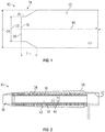
- the pitot tube 10 includes a cylindrical body portion 12 and a tip portion 14 extending along a tube axis 16 from the body portion 12 toward a tube inlet 18.
- the tip portion 14 includes an inlet opening 20 having an inlet diameter 22 smaller than a body diameter 24 of the body portion 12.
- the concave curve 26 does not extend entirely to the inlet opening 20 as the inlet diameter 22 extends axially from the inlet opening 20 to the concave curve 26. It shall be understood that the curve 26 may be straight or a profile that is aerodynamically suitable in one embodiment.
- the tip portion 14 has a tip length L.
- the length of the tip may be limited by an ability of a heating element or coils disposed inside the tip to provide heat to it. That is, if the tip is too long, the heater may not be able to heat a distal end thereof such that ice does not form or otherwise accumulate in or on the tip 14.
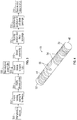
- the pitot tube 10 includes an outer tube 28 and a tube sleeve 30 disposed inside of the outer tube 28.
- the tube sleeve 30 extends along an interior of the pitot tube 10 to a tube end 32, defining a tube passage 34 from a tip portion 36 of the pitot tube 10 to the tube end 32.
- a heater coil 38 is disposed radially between the tube sleeve 30 and the outer tube 28.
- the pitot tube 10 further includes one or more water dams 40 extending inwardly from the tube sleeve 30 into the tube passage 34 and one or more drain openings 42 extending from the tube passage 34, through the tube sleeve 30 and the outer tube 28 to allow for egress of water from the pitot tube 10.
- the tube sleeve 30 is formed, in some embodiments by additive manufacturing, or by other suitable methods.
- the tube sleeve 30 is formed from a metallic material, such as a Nickel alloy, or other suitable metallic material.
- the tube sleeve 30 includes a sleeve outer surface 44 and a sleeve inner surface 46.
- the sleeve inner surface 46 defines the tube passage 34 and the one or more water dams 40 extend from the sleeve inner surface 46 into the tube passage 34.
- the tube sleeve 30 includes a sleeve wall 48 at a first sleeve end 50 that closes the tube passage 34 at the first sleeve end 50, and is open at a second sleeve end 52 opposite the first sleeve end 50.
- the tube sleeve 30 further includes one or more sleeve grooves 54 formed in the sleeve outer surface 44 to receive the heater coil 38. Additionally, protrusions 56 extend outwardly from the sleeve outer surface 44 corresponding to locations of the drain openings 42 in the completed pitot tube 10.
- the heater coil 38 is wound onto the tube sleeve 30 by inserting the heater coil 38 into the sleeve grooves 54, as shown in FIG. 6 .
- a layer of braze paste 58 is applied to the sleeve outer surface 44, covering the heater coil 38, leaving the protrusions 56, however, uncovered by the braze paste 58.
- the outer tube 28 is formed, having a through opening 60 extending from a first outer tube end 62 nearest the tip portion 36 to a second outer tube end 64.
- the outer tube 28 further includes pre-drilled openings 66 extending through the outer tube 28.
- the pre-drilled openings 66 are located at the drain opening 42 locations in the pitot tube 10, but are oversized, compared to the finished drain openings 42.
- the tube sleeve 30 is inserted into the outer tube 28, and the protrusions 56 are aligned with the pre-drilled openings 66.
- the tube sleeve 30 is inserted such that the sleeve wall 48 is located closest to the tip portion 36, thereby defining a tip cavity 68 between the sleeve wall 48 and the tip portion 36.
- the tube sleeve 30/outer tube 28 assembly is brazed in, for example, a vacuum furnace.
- step 312 and referring to FIGs.
- the predrilled openings 66 and the tip cavity 68 are filled by, for example, a laser metal deposition process, and at step 314 a selected pitot tube tip profile is formed in the filled tip cavity 68 by as illustrated in FIG. 12 by, for example, machining operations, and the drain openings 42 are drilled through the filled pre-drilled openings 66 and through the protrusions 46 as illustrated in FIG. 13 .
- the pitot tube 10 is then brazed or otherwise secured to a pitot tube strut (not shown).
- the pitot tube 10 configuration disclosed herein allows for flexibility in material choices and manufacturing method of the separate outer tube 28 and tube sleeve 30 to enhance performance of the pitot tube 10. Separate fabrication of the outer tube 28 and the tube sleeve 30 simplifies manufacturing of the pitot tube 10, thereby reducing pitot tube 10 cost. Further, the configuration encloses the heater coil 38, thereby protecting the heater coil 38 from damage or corrosion due to moisture exposure in the tube passage 34. Adding the grooves to the tube sleeve 30 aids in winding of the heater coil 38, improving the accuracy and repeatability thereof, and improves pitot tube 10 performance with consistent heater coil 38 application.
Landscapes
- Engineering & Computer Science (AREA)
- Physics & Mathematics (AREA)
- General Physics & Mathematics (AREA)
- General Engineering & Computer Science (AREA)
- Aviation & Aerospace Engineering (AREA)
- Mechanical Engineering (AREA)
- Fluid Mechanics (AREA)
- Manufacturing & Machinery (AREA)
- Microelectronics & Electronic Packaging (AREA)
- Pipe Accessories (AREA)
- Resistance Heating (AREA)
- Measuring Volume Flow (AREA)
Abstract
Description
- Exemplary embodiments pertain to the art of aircraft sensors such as pitot tubes, and more particularly to ice prevention and removal from such sensors.
- A pitot tube is widely used to determine airspeed of an aircraft or other vehicle, or to measure air or gas velocities in industrial applications. In particular, by measuring stagnation pressure of a fluid driven into the pitot tube, together with a measured static pressure, the airspeed of the aircraft can be determined. In certain flight conditions, the pitot tube may be subject to ice accumulation from moisture in the air. For this reason, pitot tubes are equipped with heating elements to prevent such ice accumulation. Further, in other conditions, the pitot tube may ingest ice crystals which then accumulate inside of the pitot tube and cause failure in its operation. A typical pitot tube is substantially cylindrical with an internal diameter containing the heating elements, or coils to prevent ice accumulation.
- In an aspect of the present invention, a pitot tube includes an outer tube extending from a first tube end to a second tube end. The second tube end defines a tip portion of the pitot tube. A tube sleeve is located inside of the outer tube and defines a tube passage extending from the first tube end to the second tube end. A heating element is located between the outer tube and the tube sleeve. The heating element is isolated from airflow into the tube passage.
- Additionally or alternatively, in this or other embodiments the tube sleeve and the outer tube are formed separately.
- Additionally or alternatively, in this or other embodiments the heating element is one or more heater coils wrapped around the tube sleeve.
- Additionally or alternatively, in this or other embodiments the tube sleeve includes one or more sleeve grooves in a sleeve outer surface to accommodate the heater coils.
- Additionally or alternatively, in this or other embodiments one or more water dams extend from the tube sleeve into the tube passage.
- Additionally or alternatively, in this or other embodiments one or more drain openings extend from the tube passage through the tube sleeve and through the outer tube.
- Additionally or alternatively, in this or other embodiments the tube sleeve is secured to the outer tube via brazing.
- Additionally or alternatively, in this or other embodiments the tube sleeve is formed by additive manufacturing.
- In another aspect of the present invention, a method of forming a pitot tube includes installing a heating element to an outer surface of a tube sleeve, the tube sleeve defining a tube passage of the pitot tube. The tube sleeve is secured in an outer tube such that the heating element is between the tube sleeve and the outer tube and is isolated from airflow through the tube passage.
- Additionally or alternatively, in this or other embodiments installing the heating element to the tube sleeve includes forming one or more sleeve grooves in the outer surface of the tube sleeve, and installing the heating element in the one or more grooves.
- Additionally or alternatively, in this or other embodiments the heating element is a heater coil.
- Additionally or alternatively, in this or other embodiments the tube sleeve is formed by additive manufacturing.
- Additionally or alternatively, in this or other embodiments a layer of braze paste is applied to the tube sleeve prior to securing the tube sleeve into the outer tube, and the tube sleeve is secured to the outer tube via brazing.
- Additionally or alternatively, in this or other embodiments one or more drain openings are formed in the pitot tube, extending from the tube passage through the tube sleeve and through the outer tube for egress of fluid from the tube passage.
- Additionally or alternatively, in this or other embodiments a tip portion of the pitot tube is plugged after securing the tube sleeve to the outer tube, and a selected tip profile shape is formed in the tip portion.
- Additionally or alternatively, in this or other embodiments the selected tip profile shape is formed by machining.
- The following descriptions should not be considered limiting in any way. With reference to the accompanying drawings, like elements are numbered alike:
-
FIG. 1 is a perspective view of an embodiment of a pitot tube; -
FIG. 2 is a cross-sectional view of an embodiment of a pitot tube; -
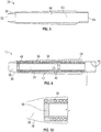
FIG. 3 is a schematic illustration of a method of making an embodiment of a pitot tube; -
FIG. 4 is a cross-sectional view of an embodiment of a tube sleeve of a pitot tube; -
FIG. 5 is another cross-sectional view of an embodiment of a tube sleeve of a pitot tube; -
FIG. 6 is an illustration of installation of a heater coil to an embodiment of a tube sleeve; -
FIG. 7 is a perspective view of an embodiment of a tube sleeve having a layer of braze paste applied thereto; -
FIG. 8 is a schematic view of an embodiment of an outer tube of a pitot tube; -
FIG. 9 is a schematic illustration of installation of a tube sleeve into an outer tube of the pitot tube; -
FIG. 10 is an illustration of filling of the tip cavity during assembly of the pitot tube; -
FIG. 11 is an illustration of filling of pre-drilled openings during manufacture of the pitot tube; -
FIG. 12 is a schematic illustration of an embodiment of a completed tip portion of a pitot tube; and -
FIG. 13 is a schematic illustration of completed drain openings of a pitot tube. - A detailed description of one or more embodiments of the disclosed apparatus and method are presented herein by way of exemplification and not limitation with reference to the Figures.
- Referring to
FIG. 1 , illustrated is an embodiment of a sensor, in this embodiment apitot tube 10. Thepitot tube 10 includes acylindrical body portion 12 and atip portion 14 extending along atube axis 16 from thebody portion 12 toward atube inlet 18. In the embodiment ofFIG. 1 , thetip portion 14 includes an inlet opening 20 having aninlet diameter 22 smaller than abody diameter 24 of thebody portion 12. Thetip portion 14, between thebody portion 12 and the inlet opening 20, tapers in diameter along aconcave curve 26. In some embodiments, theconcave curve 26 does not extend entirely to the inlet opening 20 as theinlet diameter 22 extends axially from the inlet opening 20 to theconcave curve 26. It shall be understood that thecurve 26 may be straight or a profile that is aerodynamically suitable in one embodiment. - As shown, the
tip portion 14 has a tip length L. The length of the tip may be limited by an ability of a heating element or coils disposed inside the tip to provide heat to it. That is, if the tip is too long, the heater may not be able to heat a distal end thereof such that ice does not form or otherwise accumulate in or on thetip 14. - Referring now to
FIG. 2 , thepitot tube 10 includes anouter tube 28 and atube sleeve 30 disposed inside of theouter tube 28. Thetube sleeve 30 extends along an interior of thepitot tube 10 to atube end 32, defining atube passage 34 from atip portion 36 of thepitot tube 10 to thetube end 32. Aheater coil 38 is disposed radially between thetube sleeve 30 and theouter tube 28. Thepitot tube 10 further includes one ormore water dams 40 extending inwardly from thetube sleeve 30 into thetube passage 34 and one ormore drain openings 42 extending from thetube passage 34, through thetube sleeve 30 and theouter tube 28 to allow for egress of water from thepitot tube 10. - The structure and a method of forming the
pitot tube 10 will be further described below with reference to the flow diagram ofFIG. 3 and toFIGs. 4-13 . Atblock 300 ofFIG. 3 , thetube sleeve 30 is formed, in some embodiments by additive manufacturing, or by other suitable methods. Thetube sleeve 30 is formed from a metallic material, such as a Nickel alloy, or other suitable metallic material. - As illustrated in
FIGs. 4 and5 , thetube sleeve 30 includes a sleeveouter surface 44 and a sleeveinner surface 46. The sleeveinner surface 46 defines thetube passage 34 and the one ormore water dams 40 extend from the sleeveinner surface 46 into thetube passage 34. Thetube sleeve 30 includes asleeve wall 48 at afirst sleeve end 50 that closes thetube passage 34 at thefirst sleeve end 50, and is open at asecond sleeve end 52 opposite thefirst sleeve end 50. Thetube sleeve 30 further includes one ormore sleeve grooves 54 formed in the sleeveouter surface 44 to receive theheater coil 38. Additionally,protrusions 56 extend outwardly from the sleeveouter surface 44 corresponding to locations of thedrain openings 42 in the completedpitot tube 10. - In
block 302 ofFIG. 3 , theheater coil 38 is wound onto thetube sleeve 30 by inserting theheater coil 38 into thesleeve grooves 54, as shown inFIG. 6 . Inblock 304 ofFIG. 3 , and as shown inFIG. 7 , a layer ofbraze paste 58 is applied to the sleeveouter surface 44, covering theheater coil 38, leaving theprotrusions 56, however, uncovered by thebraze paste 58. - In
block 306 and as shown inFIG. 8 , theouter tube 28 is formed, having a throughopening 60 extending from a firstouter tube end 62 nearest thetip portion 36 to a secondouter tube end 64. Theouter tube 28 further includespre-drilled openings 66 extending through theouter tube 28. Thepre-drilled openings 66 are located at the drain opening 42 locations in thepitot tube 10, but are oversized, compared to thefinished drain openings 42. - In
block 308, and as shown inFIG. 9 , thetube sleeve 30 is inserted into theouter tube 28, and theprotrusions 56 are aligned with thepre-drilled openings 66. Thetube sleeve 30 is inserted such that thesleeve wall 48 is located closest to thetip portion 36, thereby defining atip cavity 68 between thesleeve wall 48 and thetip portion 36. Atstep 310, thetube sleeve 30/outer tube 28 assembly is brazed in, for example, a vacuum furnace. Atstep 312, and referring toFIGs. 10 and11 , thepredrilled openings 66 and thetip cavity 68 are filled by, for example, a laser metal deposition process, and at step 314 a selected pitot tube tip profile is formed in the filledtip cavity 68 by as illustrated inFIG. 12 by, for example, machining operations, and thedrain openings 42 are drilled through the filledpre-drilled openings 66 and through theprotrusions 46 as illustrated inFIG. 13 . Atblock 316, thepitot tube 10 is then brazed or otherwise secured to a pitot tube strut (not shown). - The
pitot tube 10 configuration disclosed herein allows for flexibility in material choices and manufacturing method of the separateouter tube 28 andtube sleeve 30 to enhance performance of thepitot tube 10. Separate fabrication of theouter tube 28 and thetube sleeve 30 simplifies manufacturing of thepitot tube 10, thereby reducingpitot tube 10 cost. Further, the configuration encloses theheater coil 38, thereby protecting theheater coil 38 from damage or corrosion due to moisture exposure in thetube passage 34. Adding the grooves to thetube sleeve 30 aids in winding of theheater coil 38, improving the accuracy and repeatability thereof, and improvespitot tube 10 performance withconsistent heater coil 38 application. - The term "about" is intended to include the degree of error associated with measurement of the particular quantity based upon the equipment available at the time of filing the application.
- The terminology used herein is for the purpose of describing particular embodiments only and is not intended to be limiting of the present disclosure. As used herein, the singular forms "a", "an" and "the" are intended to include the plural forms as well, unless the context clearly indicates otherwise. It will be further understood that the terms "comprises" and/or "comprising," when used in this specification, specify the presence of stated features, integers, steps, operations, elements, and/or components, but do not preclude the presence or addition of one or more other features, integers, steps, operations, element components, and/or groups thereof.
- While the present disclosure has been described with reference to an exemplary embodiment or embodiments, it will be understood by those skilled in the art that various changes may be made and equivalents may be substituted for elements thereof without departing from the scope of the present disclosure. In addition, many modifications may be made to adapt a particular situation or material to the teachings of the present disclosure without departing from the essential scope thereof. Therefore, it is intended that the present disclosure not be limited to the particular embodiment disclosed as the best mode contemplated for carrying out this present disclosure, but that the present disclosure will include all embodiments falling within the scope of the claims.
Claims (15)
- A pitot tube (10), comprising:an outer tube (28) extending from a first tube end (62) to a second tube end (64), the first tube end (62) defining a tip portion (36) of the pitot tube (10);a tube sleeve (30) inside of the outer tube (28) defining a tube passage (34) extending from the first tube end (62) to the second tube end (64); anda heating element between the outer tube (28) and the tube sleeve (30), the heating element being isolated from airflow into the tube passage (34).
- The pitot tube of claim 1, wherein the tube sleeve (30) and the outer tube (28) are formed separately.
- The pitot tube of claim 1 or 2, wherein the heating element is one or more heater coils (38) wrapped around the tube sleeve (30), wherein, optionally, the tube sleeve (30) includes one or more sleeve grooves (54) in a sleeve outer surface (44) to accommodate the heater coils (38).
- The pitot tube of any preceding claim, further comprising one or more water dams (40) extending from the tube sleeve (30) into the tube passage (34).
- The pitot tube of any preceding claim, further comprising one or more drain openings (42) extending from the tube passage (34) through the tube sleeve (30) and through the outer tube (28).
- The pitot tube of any preceding claim, wherein the tube sleeve (30) is secured to the outer tube (28) via brazing.
- The pitot tube of any preceding claim, wherein the tube sleeve (30) is formed by additive manufacturing.
- A method of forming a pitot tube (10), comprising:installing a heating element to an outer surface of a tube sleeve (30), the tube sleeve (30) defining a tube passage (34) of the pitot tube (10); andsecuring the tube sleeve (30) in an outer tube (28) such that the heating element is between the tube sleeve (30) and the outer tube (28) and is isolated from airflow through the tube passage (34).
- The method of claim 8, wherein installing the heating element to the tube sleeve (30) comprises:forming one or more sleeve grooves (54) in the outer surface of the tube sleeve (30); andinstalling the heating element in the one or more grooves.
- The method of claim 8 or 9, wherein the heating element is a heater coil (38).
- The method of any of claims 8 to 10, further comprising forming the tube sleeve (30) by additive manufacturing.
- The method of any of claims 8 to 11, further comprising:applying a layer of braze paste to the tube sleeve (30) prior to securing the tube sleeve (30) into the outer tube (28); andsecuring the tube sleeve (30) to the outer tube (28) via brazing.
- The method of any of claims 8 to 12, further comprising forming one or more drain openings (42) in the pitot tube (10), extending from the tube passage (34) through the tube sleeve (30) and through the outer tube (28) for egress of fluid from the tube passage (34).
- The method of any of claims 8 to 13, further comprising:plugging a tip portion (36) of the pitot tube (10) after securing the tube sleeve (30) to the outer tube (28); andforming a selected tip profile shape in the tip portion (36).
- The method of claim 14, wherein the selected tip profile shape is formed by machining.
Applications Claiming Priority (1)
| Application Number | Priority Date | Filing Date | Title |
|---|---|---|---|
| IN201811037757 | 2018-10-05 |
Publications (2)
| Publication Number | Publication Date |
|---|---|
| EP3633387A1 true EP3633387A1 (en) | 2020-04-08 |
| EP3633387B1 EP3633387B1 (en) | 2024-07-24 |
Family
ID=68158931
Family Applications (1)
| Application Number | Title | Priority Date | Filing Date |
|---|---|---|---|
| EP19201456.1A Active EP3633387B1 (en) | 2018-10-05 | 2019-10-04 | Pitot tube heater assembly |
Country Status (2)
| Country | Link |
|---|---|
| US (2) | US11262227B2 (en) |
| EP (1) | EP3633387B1 (en) |
Families Citing this family (11)
| Publication number | Priority date | Publication date | Assignee | Title |
|---|---|---|---|---|
| US11209330B2 (en) * | 2015-03-23 | 2021-12-28 | Rosemount Aerospace Inc. | Corrosion resistant sleeve for an air data probe |
| US11414195B2 (en) | 2018-03-23 | 2022-08-16 | Rosemount Aerospace Inc. | Surface modified heater assembly |
| US11262227B2 (en) | 2018-10-05 | 2022-03-01 | Rosemount Aerospace Inc. | Pitot tube heater assembly |
| US11131686B2 (en) * | 2019-02-01 | 2021-09-28 | Rosemount Aerospace Inc. | Process for manufacturing a pitot tube having a graphite insert embedded therein |
| US11428707B2 (en) | 2019-06-14 | 2022-08-30 | Rosemount Aerospace Inc. | Air data probe with weld sealed insert |
| CN113619779B (en) * | 2021-08-16 | 2023-06-02 | 佛山智壹科技有限公司 | fixed-wing drone |
| US11624637B1 (en) | 2021-10-01 | 2023-04-11 | Rosemount Aerospace Inc | Air data probe with integrated heater bore and features |
| US11662235B2 (en) | 2021-10-01 | 2023-05-30 | Rosemount Aerospace Inc. | Air data probe with enhanced conduction integrated heater bore and features |
| US11845136B2 (en) * | 2021-11-24 | 2023-12-19 | Rosemount Aerospace Inc. | Anti-corrosive braze coatings |
| US12535499B2 (en) | 2023-05-24 | 2026-01-27 | Rosemount Aerospace Inc. | Bulkheads and water dams for air data probes |
| KR102678498B1 (en) * | 2023-12-07 | 2024-06-25 | 이재우 | Heating apparatus for defrosting ice |
Citations (5)
| Publication number | Priority date | Publication date | Assignee | Title |
|---|---|---|---|---|
| US3364742A (en) * | 1964-06-26 | 1968-01-23 | Rosemount Eng Co Ltd | Dual pitot and/or static system |
| EP3073275A2 (en) * | 2015-03-23 | 2016-09-28 | Rosemount Aerospace Inc. | Moisture resistant air data probe |
| EP3133403A1 (en) * | 2015-08-20 | 2017-02-22 | Honeywell International Inc. | Systems and methods for additive manufacturing for air data probes |
| US20170101190A1 (en) * | 2015-10-08 | 2017-04-13 | Honeywell International Inc. | Air data probe with double helical coil heater cable |
| US20180259548A1 (en) * | 2017-03-13 | 2018-09-13 | Honeywell International Inc. | Arrangement of dams in air data probe |
Family Cites Families (21)
| Publication number | Priority date | Publication date | Assignee | Title |
|---|---|---|---|---|
| CA1198266A (en) * | 1982-12-17 | 1985-12-24 | Jobst U. Gellert | Method of manufacture of an injection molding integral heated probe |
| US5046360A (en) * | 1989-12-15 | 1991-09-10 | Rosemount Inc. | Aerodynamic probe internal constructions |
| JP2001505659A (en) | 1996-10-16 | 2001-04-24 | ローズマウント・エアロスペース・インコーポレーテッド | Heated air data probe |
| DE19943192A1 (en) * | 1999-09-09 | 2001-04-05 | Hotset Heizpatronen Zubehoer | Tubular heating element |
| US6591696B2 (en) * | 2001-07-12 | 2003-07-15 | Rosemount Aerospace, Inc. | Integral electric pressure probe for aircraft |
| FR2833347B1 (en) | 2001-12-11 | 2004-02-27 | Thales Sa | MULTIFUNCTIONAL PROBE FOR AIRCRAFT |
| US6892584B2 (en) * | 2002-11-19 | 2005-05-17 | Rosemount Aerospace Inc. | Fabricated pitot probe assembly |
| US20100116806A1 (en) * | 2007-05-08 | 2010-05-13 | Honeywell International Inc. | Automated heating system for ports susceptible to icing |
| WO2012004763A1 (en) * | 2010-07-07 | 2012-01-12 | Jan Petrus Human | Heating elements |
| EP2728364B1 (en) | 2012-10-31 | 2019-04-17 | Rosemount Aerospace Inc. | Ice resistant pitot tube |
| US20160304210A1 (en) | 2014-10-15 | 2016-10-20 | Rosemount Aerospace Inc. | One-piece air data probe |
| CA2919341C (en) * | 2015-04-02 | 2022-11-15 | Rosemount Aerospace, Inc. | Corrosion-resistant heated air data probe |
| US9606137B2 (en) * | 2015-06-17 | 2017-03-28 | Rosemount Aerospace Inc. | Enhancements for differential-pressure-driven fluid flows |
| US9791304B2 (en) * | 2015-10-21 | 2017-10-17 | Honeywell International Inc. | Air data probe heater utilizing low melting point metal |
| US9891083B2 (en) | 2016-01-08 | 2018-02-13 | Honeywell International Inc. | Probe tip for air data probe |
| US10384787B2 (en) | 2016-06-23 | 2019-08-20 | Honeywell International Inc. | Forming an air data probe from a porous cover and brazing material |
| US10197588B2 (en) * | 2016-11-09 | 2019-02-05 | Honeywell International Inc. | Thin film heating systems for air data probes |
| US11221346B2 (en) * | 2017-03-13 | 2022-01-11 | Honeywell International Inc. | Ice prevention dam for, and method for forming, a pitot tube |
| US11262227B2 (en) | 2018-10-05 | 2022-03-01 | Rosemount Aerospace Inc. | Pitot tube heater assembly |
| US10884014B2 (en) * | 2019-03-25 | 2021-01-05 | Rosemount Aerospace Inc. | Air data probe with fully-encapsulated heater |
| US11428707B2 (en) * | 2019-06-14 | 2022-08-30 | Rosemount Aerospace Inc. | Air data probe with weld sealed insert |
-
2019
- 2019-09-23 US US16/578,561 patent/US11262227B2/en active Active
- 2019-10-04 EP EP19201456.1A patent/EP3633387B1/en active Active
-
2022
- 2022-01-19 US US17/578,653 patent/US12198839B2/en active Active
Patent Citations (5)
| Publication number | Priority date | Publication date | Assignee | Title |
|---|---|---|---|---|
| US3364742A (en) * | 1964-06-26 | 1968-01-23 | Rosemount Eng Co Ltd | Dual pitot and/or static system |
| EP3073275A2 (en) * | 2015-03-23 | 2016-09-28 | Rosemount Aerospace Inc. | Moisture resistant air data probe |
| EP3133403A1 (en) * | 2015-08-20 | 2017-02-22 | Honeywell International Inc. | Systems and methods for additive manufacturing for air data probes |
| US20170101190A1 (en) * | 2015-10-08 | 2017-04-13 | Honeywell International Inc. | Air data probe with double helical coil heater cable |
| US20180259548A1 (en) * | 2017-03-13 | 2018-09-13 | Honeywell International Inc. | Arrangement of dams in air data probe |
Also Published As
| Publication number | Publication date |
|---|---|
| US11262227B2 (en) | 2022-03-01 |
| US20200109982A1 (en) | 2020-04-09 |
| US20220136884A1 (en) | 2022-05-05 |
| US12198839B2 (en) | 2025-01-14 |
| EP3633387B1 (en) | 2024-07-24 |
Similar Documents
| Publication | Publication Date | Title |
|---|---|---|
| US12198839B2 (en) | Pitot tube heater assembly | |
| EP3683584A1 (en) | Pitot tube | |
| US12055559B2 (en) | Hybrid material aircraft sensors and method of manufacturing | |
| EP3499217B1 (en) | Air data probe with a heater coil protection arrangement | |
| EP3650867B1 (en) | Swaged mandrel pitot | |
| EP3715859B1 (en) | Air data probe with fully-encapsulated heater | |
| EP4224173B1 (en) | Air data probe with weld sealed insert | |
| EP3514551A1 (en) | Air data probe and assembly method | |
| CN105987765A (en) | Air Data Probe | |
| EP3199955A1 (en) | Pitot tube with thermally conductive insert | |
| US11866179B2 (en) | Surface modified heater assembly | |
| US11209330B2 (en) | Corrosion resistant sleeve for an air data probe | |
| US20240060803A1 (en) | Fluid resistance element, fluid controller, and method of manufacturing fluid resistance element | |
| RU2849316C1 (en) | Air pressure receiver | |
| BR102020000913B1 (en) | PITOT TUBE AND METHOD FOR FORMING A PITOT TUBE | |
| JPH07120286A (en) | Heating resistor for thermal air flow meter |
Legal Events
| Date | Code | Title | Description |
|---|---|---|---|
| PUAI | Public reference made under article 153(3) epc to a published international application that has entered the european phase |
Free format text: ORIGINAL CODE: 0009012 |
|
| STAA | Information on the status of an ep patent application or granted ep patent |
Free format text: STATUS: THE APPLICATION HAS BEEN PUBLISHED |
|
| AK | Designated contracting states |
Kind code of ref document: A1 Designated state(s): AL AT BE BG CH CY CZ DE DK EE ES FI FR GB GR HR HU IE IS IT LI LT LU LV MC MK MT NL NO PL PT RO RS SE SI SK SM TR |
|
| AX | Request for extension of the european patent |
Extension state: BA ME |
|
| STAA | Information on the status of an ep patent application or granted ep patent |
Free format text: STATUS: REQUEST FOR EXAMINATION WAS MADE |
|
| 17P | Request for examination filed |
Effective date: 20201007 |
|
| RBV | Designated contracting states (corrected) |
Designated state(s): AL AT BE BG CH CY CZ DE DK EE ES FI FR GB GR HR HU IE IS IT LI LT LU LV MC MK MT NL NO PL PT RO RS SE SI SK SM TR |
|
| STAA | Information on the status of an ep patent application or granted ep patent |
Free format text: STATUS: EXAMINATION IS IN PROGRESS |
|
| 17Q | First examination report despatched |
Effective date: 20220503 |
|
| GRAP | Despatch of communication of intention to grant a patent |
Free format text: ORIGINAL CODE: EPIDOSNIGR1 |
|
| STAA | Information on the status of an ep patent application or granted ep patent |
Free format text: STATUS: GRANT OF PATENT IS INTENDED |
|
| INTG | Intention to grant announced |
Effective date: 20240228 |
|
| RIN1 | Information on inventor provided before grant (corrected) |
Inventor name: MAHAPATRA, GURU PRASAD Inventor name: JACOB, ROBIN Inventor name: JOHNSON, PAUL ROBERT |
|
| GRAS | Grant fee paid |
Free format text: ORIGINAL CODE: EPIDOSNIGR3 |
|
| GRAA | (expected) grant |
Free format text: ORIGINAL CODE: 0009210 |
|
| STAA | Information on the status of an ep patent application or granted ep patent |
Free format text: STATUS: THE PATENT HAS BEEN GRANTED |
|
| AK | Designated contracting states |
Kind code of ref document: B1 Designated state(s): AL AT BE BG CH CY CZ DE DK EE ES FI FR GB GR HR HU IE IS IT LI LT LU LV MC MK MT NL NO PL PT RO RS SE SI SK SM TR |
|
| REG | Reference to a national code |
Ref country code: GB Ref legal event code: FG4D |
|
| REG | Reference to a national code |
Ref country code: CH Ref legal event code: EP |
|
| REG | Reference to a national code |
Ref country code: DE Ref legal event code: R096 Ref document number: 602019055616 Country of ref document: DE |
|
| REG | Reference to a national code |
Ref country code: IE Ref legal event code: FG4D |
|
| REG | Reference to a national code |
Ref country code: LT Ref legal event code: MG9D |
|
| REG | Reference to a national code |
Ref country code: NL Ref legal event code: MP Effective date: 20240724 |
|
| PG25 | Lapsed in a contracting state [announced via postgrant information from national office to epo] |
Ref country code: PT Free format text: LAPSE BECAUSE OF FAILURE TO SUBMIT A TRANSLATION OF THE DESCRIPTION OR TO PAY THE FEE WITHIN THE PRESCRIBED TIME-LIMIT Effective date: 20241125 |
|
| REG | Reference to a national code |
Ref country code: AT Ref legal event code: MK05 Ref document number: 1706769 Country of ref document: AT Kind code of ref document: T Effective date: 20240724 |
|
| PG25 | Lapsed in a contracting state [announced via postgrant information from national office to epo] |
Ref country code: NL Free format text: LAPSE BECAUSE OF FAILURE TO SUBMIT A TRANSLATION OF THE DESCRIPTION OR TO PAY THE FEE WITHIN THE PRESCRIBED TIME-LIMIT Effective date: 20240724 |
|
| PG25 | Lapsed in a contracting state [announced via postgrant information from national office to epo] |
Ref country code: PT Free format text: LAPSE BECAUSE OF FAILURE TO SUBMIT A TRANSLATION OF THE DESCRIPTION OR TO PAY THE FEE WITHIN THE PRESCRIBED TIME-LIMIT Effective date: 20241125 Ref country code: NL Free format text: LAPSE BECAUSE OF FAILURE TO SUBMIT A TRANSLATION OF THE DESCRIPTION OR TO PAY THE FEE WITHIN THE PRESCRIBED TIME-LIMIT Effective date: 20240724 |
|
| PG25 | Lapsed in a contracting state [announced via postgrant information from national office to epo] |
Ref country code: NO Free format text: LAPSE BECAUSE OF FAILURE TO SUBMIT A TRANSLATION OF THE DESCRIPTION OR TO PAY THE FEE WITHIN THE PRESCRIBED TIME-LIMIT Effective date: 20241024 |
|
| PG25 | Lapsed in a contracting state [announced via postgrant information from national office to epo] |
Ref country code: GR Free format text: LAPSE BECAUSE OF FAILURE TO SUBMIT A TRANSLATION OF THE DESCRIPTION OR TO PAY THE FEE WITHIN THE PRESCRIBED TIME-LIMIT Effective date: 20241025 Ref country code: PL Free format text: LAPSE BECAUSE OF FAILURE TO SUBMIT A TRANSLATION OF THE DESCRIPTION OR TO PAY THE FEE WITHIN THE PRESCRIBED TIME-LIMIT Effective date: 20240724 Ref country code: FI Free format text: LAPSE BECAUSE OF FAILURE TO SUBMIT A TRANSLATION OF THE DESCRIPTION OR TO PAY THE FEE WITHIN THE PRESCRIBED TIME-LIMIT Effective date: 20240724 |
|
| PG25 | Lapsed in a contracting state [announced via postgrant information from national office to epo] |
Ref country code: BG Free format text: LAPSE BECAUSE OF FAILURE TO SUBMIT A TRANSLATION OF THE DESCRIPTION OR TO PAY THE FEE WITHIN THE PRESCRIBED TIME-LIMIT Effective date: 20240724 |
|
| PG25 | Lapsed in a contracting state [announced via postgrant information from national office to epo] |
Ref country code: LV Free format text: LAPSE BECAUSE OF FAILURE TO SUBMIT A TRANSLATION OF THE DESCRIPTION OR TO PAY THE FEE WITHIN THE PRESCRIBED TIME-LIMIT Effective date: 20240724 |
|
| PG25 | Lapsed in a contracting state [announced via postgrant information from national office to epo] |
Ref country code: IS Free format text: LAPSE BECAUSE OF FAILURE TO SUBMIT A TRANSLATION OF THE DESCRIPTION OR TO PAY THE FEE WITHIN THE PRESCRIBED TIME-LIMIT Effective date: 20241124 Ref country code: AT Free format text: LAPSE BECAUSE OF FAILURE TO SUBMIT A TRANSLATION OF THE DESCRIPTION OR TO PAY THE FEE WITHIN THE PRESCRIBED TIME-LIMIT Effective date: 20240724 |
|
| PG25 | Lapsed in a contracting state [announced via postgrant information from national office to epo] |
Ref country code: HR Free format text: LAPSE BECAUSE OF FAILURE TO SUBMIT A TRANSLATION OF THE DESCRIPTION OR TO PAY THE FEE WITHIN THE PRESCRIBED TIME-LIMIT Effective date: 20240724 |
|
| PG25 | Lapsed in a contracting state [announced via postgrant information from national office to epo] |
Ref country code: RS Free format text: LAPSE BECAUSE OF FAILURE TO SUBMIT A TRANSLATION OF THE DESCRIPTION OR TO PAY THE FEE WITHIN THE PRESCRIBED TIME-LIMIT Effective date: 20241024 Ref country code: ES Free format text: LAPSE BECAUSE OF FAILURE TO SUBMIT A TRANSLATION OF THE DESCRIPTION OR TO PAY THE FEE WITHIN THE PRESCRIBED TIME-LIMIT Effective date: 20240724 |
|
| PG25 | Lapsed in a contracting state [announced via postgrant information from national office to epo] |
Ref country code: RS Free format text: LAPSE BECAUSE OF FAILURE TO SUBMIT A TRANSLATION OF THE DESCRIPTION OR TO PAY THE FEE WITHIN THE PRESCRIBED TIME-LIMIT Effective date: 20241024 Ref country code: PL Free format text: LAPSE BECAUSE OF FAILURE TO SUBMIT A TRANSLATION OF THE DESCRIPTION OR TO PAY THE FEE WITHIN THE PRESCRIBED TIME-LIMIT Effective date: 20240724 Ref country code: NO Free format text: LAPSE BECAUSE OF FAILURE TO SUBMIT A TRANSLATION OF THE DESCRIPTION OR TO PAY THE FEE WITHIN THE PRESCRIBED TIME-LIMIT Effective date: 20241024 Ref country code: LV Free format text: LAPSE BECAUSE OF FAILURE TO SUBMIT A TRANSLATION OF THE DESCRIPTION OR TO PAY THE FEE WITHIN THE PRESCRIBED TIME-LIMIT Effective date: 20240724 Ref country code: IS Free format text: LAPSE BECAUSE OF FAILURE TO SUBMIT A TRANSLATION OF THE DESCRIPTION OR TO PAY THE FEE WITHIN THE PRESCRIBED TIME-LIMIT Effective date: 20241124 Ref country code: HR Free format text: LAPSE BECAUSE OF FAILURE TO SUBMIT A TRANSLATION OF THE DESCRIPTION OR TO PAY THE FEE WITHIN THE PRESCRIBED TIME-LIMIT Effective date: 20240724 Ref country code: GR Free format text: LAPSE BECAUSE OF FAILURE TO SUBMIT A TRANSLATION OF THE DESCRIPTION OR TO PAY THE FEE WITHIN THE PRESCRIBED TIME-LIMIT Effective date: 20241025 Ref country code: FI Free format text: LAPSE BECAUSE OF FAILURE TO SUBMIT A TRANSLATION OF THE DESCRIPTION OR TO PAY THE FEE WITHIN THE PRESCRIBED TIME-LIMIT Effective date: 20240724 Ref country code: ES Free format text: LAPSE BECAUSE OF FAILURE TO SUBMIT A TRANSLATION OF THE DESCRIPTION OR TO PAY THE FEE WITHIN THE PRESCRIBED TIME-LIMIT Effective date: 20240724 Ref country code: BG Free format text: LAPSE BECAUSE OF FAILURE TO SUBMIT A TRANSLATION OF THE DESCRIPTION OR TO PAY THE FEE WITHIN THE PRESCRIBED TIME-LIMIT Effective date: 20240724 Ref country code: AT Free format text: LAPSE BECAUSE OF FAILURE TO SUBMIT A TRANSLATION OF THE DESCRIPTION OR TO PAY THE FEE WITHIN THE PRESCRIBED TIME-LIMIT Effective date: 20240724 |
|
| PG25 | Lapsed in a contracting state [announced via postgrant information from national office to epo] |
Ref country code: RO Free format text: LAPSE BECAUSE OF FAILURE TO SUBMIT A TRANSLATION OF THE DESCRIPTION OR TO PAY THE FEE WITHIN THE PRESCRIBED TIME-LIMIT Effective date: 20240724 Ref country code: DK Free format text: LAPSE BECAUSE OF FAILURE TO SUBMIT A TRANSLATION OF THE DESCRIPTION OR TO PAY THE FEE WITHIN THE PRESCRIBED TIME-LIMIT Effective date: 20240724 Ref country code: SM Free format text: LAPSE BECAUSE OF FAILURE TO SUBMIT A TRANSLATION OF THE DESCRIPTION OR TO PAY THE FEE WITHIN THE PRESCRIBED TIME-LIMIT Effective date: 20240724 |
|
| PG25 | Lapsed in a contracting state [announced via postgrant information from national office to epo] |
Ref country code: EE Free format text: LAPSE BECAUSE OF FAILURE TO SUBMIT A TRANSLATION OF THE DESCRIPTION OR TO PAY THE FEE WITHIN THE PRESCRIBED TIME-LIMIT Effective date: 20240724 |
|
| PG25 | Lapsed in a contracting state [announced via postgrant information from national office to epo] |
Ref country code: CZ Free format text: LAPSE BECAUSE OF FAILURE TO SUBMIT A TRANSLATION OF THE DESCRIPTION OR TO PAY THE FEE WITHIN THE PRESCRIBED TIME-LIMIT Effective date: 20240724 |
|
| REG | Reference to a national code |
Ref country code: DE Ref legal event code: R097 Ref document number: 602019055616 Country of ref document: DE |
|
| PG25 | Lapsed in a contracting state [announced via postgrant information from national office to epo] |
Ref country code: IT Free format text: LAPSE BECAUSE OF FAILURE TO SUBMIT A TRANSLATION OF THE DESCRIPTION OR TO PAY THE FEE WITHIN THE PRESCRIBED TIME-LIMIT Effective date: 20240724 Ref country code: SK Free format text: LAPSE BECAUSE OF FAILURE TO SUBMIT A TRANSLATION OF THE DESCRIPTION OR TO PAY THE FEE WITHIN THE PRESCRIBED TIME-LIMIT Effective date: 20240724 |
|
| PLBE | No opposition filed within time limit |
Free format text: ORIGINAL CODE: 0009261 |
|
| STAA | Information on the status of an ep patent application or granted ep patent |
Free format text: STATUS: NO OPPOSITION FILED WITHIN TIME LIMIT |
|
| REG | Reference to a national code |
Ref country code: CH Ref legal event code: PL |
|
| 26N | No opposition filed |
Effective date: 20250425 |
|
| PG25 | Lapsed in a contracting state [announced via postgrant information from national office to epo] |
Ref country code: MC Free format text: LAPSE BECAUSE OF FAILURE TO SUBMIT A TRANSLATION OF THE DESCRIPTION OR TO PAY THE FEE WITHIN THE PRESCRIBED TIME-LIMIT Effective date: 20240724 |
|
| PG25 | Lapsed in a contracting state [announced via postgrant information from national office to epo] |
Ref country code: BE Free format text: LAPSE BECAUSE OF NON-PAYMENT OF DUE FEES Effective date: 20241031 Ref country code: LU Free format text: LAPSE BECAUSE OF NON-PAYMENT OF DUE FEES Effective date: 20241004 |
|
| PG25 | Lapsed in a contracting state [announced via postgrant information from national office to epo] |
Ref country code: CH Free format text: LAPSE BECAUSE OF NON-PAYMENT OF DUE FEES Effective date: 20241031 |
|
| REG | Reference to a national code |
Ref country code: BE Ref legal event code: MM Effective date: 20241031 |
|
| PG25 | Lapsed in a contracting state [announced via postgrant information from national office to epo] |
Ref country code: SE Free format text: LAPSE BECAUSE OF FAILURE TO SUBMIT A TRANSLATION OF THE DESCRIPTION OR TO PAY THE FEE WITHIN THE PRESCRIBED TIME-LIMIT Effective date: 20240724 |
|
| PGFP | Annual fee paid to national office [announced via postgrant information from national office to epo] |
Ref country code: GB Payment date: 20250923 Year of fee payment: 7 |
|
| PGFP | Annual fee paid to national office [announced via postgrant information from national office to epo] |
Ref country code: FR Payment date: 20250924 Year of fee payment: 7 |
|
| PG25 | Lapsed in a contracting state [announced via postgrant information from national office to epo] |
Ref country code: IE Free format text: LAPSE BECAUSE OF NON-PAYMENT OF DUE FEES Effective date: 20241004 |
|
| PGFP | Annual fee paid to national office [announced via postgrant information from national office to epo] |
Ref country code: DE Payment date: 20250923 Year of fee payment: 7 |
|
| PG25 | Lapsed in a contracting state [announced via postgrant information from national office to epo] |
Ref country code: CY Free format text: LAPSE BECAUSE OF FAILURE TO SUBMIT A TRANSLATION OF THE DESCRIPTION OR TO PAY THE FEE WITHIN THE PRESCRIBED TIME-LIMIT; INVALID AB INITIO Effective date: 20191004 |
|
| PG25 | Lapsed in a contracting state [announced via postgrant information from national office to epo] |
Ref country code: HU Free format text: LAPSE BECAUSE OF FAILURE TO SUBMIT A TRANSLATION OF THE DESCRIPTION OR TO PAY THE FEE WITHIN THE PRESCRIBED TIME-LIMIT; INVALID AB INITIO Effective date: 20191004 |