EP3633365A1 - Sample plate for pesi ion source and mass spectrometer using said sample plate - Google Patents
Sample plate for pesi ion source and mass spectrometer using said sample plate Download PDFInfo
- Publication number
- EP3633365A1 EP3633365A1 EP17911536.5A EP17911536A EP3633365A1 EP 3633365 A1 EP3633365 A1 EP 3633365A1 EP 17911536 A EP17911536 A EP 17911536A EP 3633365 A1 EP3633365 A1 EP 3633365A1
- Authority
- EP
- European Patent Office
- Prior art keywords
- sample
- plate
- lid
- concave portion
- probe
- Prior art date
- Legal status (The legal status is an assumption and is not a legal conclusion. Google has not performed a legal analysis and makes no representation as to the accuracy of the status listed.)
- Granted
Links
Images




Classifications
-
- H—ELECTRICITY
- H01—ELECTRIC ELEMENTS
- H01J—ELECTRIC DISCHARGE TUBES OR DISCHARGE LAMPS
- H01J49/00—Particle spectrometers or separator tubes
- H01J49/02—Details
- H01J49/04—Arrangements for introducing or extracting samples to be analysed, e.g. vacuum locks; Arrangements for external adjustment of electron- or ion-optical components
- H01J49/0409—Sample holders or containers
-
- G—PHYSICS
- G01—MEASURING; TESTING
- G01N—INVESTIGATING OR ANALYSING MATERIALS BY DETERMINING THEIR CHEMICAL OR PHYSICAL PROPERTIES
- G01N27/00—Investigating or analysing materials by the use of electric, electrochemical, or magnetic means
- G01N27/62—Investigating or analysing materials by the use of electric, electrochemical, or magnetic means by investigating the ionisation of gases, e.g. aerosols; by investigating electric discharges, e.g. emission of cathode
- G01N27/622—Ion mobility spectrometry
- G01N27/623—Ion mobility spectrometry combined with mass spectrometry
-
- H—ELECTRICITY
- H01—ELECTRIC ELEMENTS
- H01J—ELECTRIC DISCHARGE TUBES OR DISCHARGE LAMPS
- H01J49/00—Particle spectrometers or separator tubes
- H01J49/02—Details
- H01J49/10—Ion sources; Ion guns
- H01J49/14—Ion sources; Ion guns using particle bombardment, e.g. ionisation chambers
-
- H—ELECTRICITY
- H01—ELECTRIC ELEMENTS
- H01J—ELECTRIC DISCHARGE TUBES OR DISCHARGE LAMPS
- H01J49/00—Particle spectrometers or separator tubes
- H01J49/02—Details
- H01J49/10—Ion sources; Ion guns
- H01J49/16—Ion sources; Ion guns using surface ionisation, e.g. field-, thermionic- or photo-emission
- H01J49/165—Electrospray ionisation
Definitions
- the present invention relates to a sample plate for an ion source employing a probe electrospray ionization (PESI) method, as well as a mass spectrometer in which such a sample plate is used to perform a measurement.
- PESI probe electrospray ionization
- ESI electrospray ionization
- a PESI ion source includes: an electrically conductive probe having a tip with a diameter of several hundred nanometers; a position-changing unit for changing the position of one or both of the probe and a sample so as to make the sample adhere to the tip of the probe; and a high voltage generator for applying a high voltage to the probe with the sample collected on the tip of the probe.
- the position-changing unit is operated to change the position of one or both of the probe and the sample so that the tip of the probe comes in contact with or slightly pierces the sample and makes a trace amount of sample adhere to the tip surface of the probe.
- the position-changing unit is subsequently operated to remove the probe from the sample, and a high voltage is applied from the high-voltage generator to the probe. Then, a strong electric field acts on the sample adhered to the tip of the probe and induces the electrospray phenomenon, which causes the molecules of the components in the sample to be ionized while being released.
- both a solid sample, such as a biological tissue section, and a liquid sample, such as blood, can be treated as a sample to be subjected to the measurement.
- a mass spectrometer using a PESI ion source is hereinafter simply called the "mass spectrometer"
- the mass spectrometer when a measurement for a solid sample is to be performed, it is normally the case that the sample is directly placed on a sample stage, or the sample is placed on a plate held on the sample stage. Then, the sample is pierced with the lowered probe to make the sample adhere to the tip of the probe (see Patent Literature 2 or other related documents).
- a container holding the liquid sample is placed on the sample stage, and the probe is dipped in the liquid sample in the container to make the sample adhere to the tip of the probe.
- a capillary tube through which the liquid sample is supplied is provided so that its outlet end is located within the movable range of the probe, thereby allowing the probe to come in contact with a droplet formed at the outlet end of the capillary tube due to the supply of the liquid sample.
- the measurement task will be extremely cumbersome and significantly lower the measurement efficiency if a measurement for a liquid sample is inserted into a series of measurements for a plurality of solid samples, or conversely, if a measurement for a solid sample is inserted into a series of measurements for a plurality of liquid samples.
- Non Patent Literature 1 Sen Takeda and even other authors, "Developing a Novel Cancer Diagnostic System Based on the Mass Spectrometry and Learning Machine", Shimadzu Review, Vol. 69, No. 3/4, March 2013
- the present invention has been developed to solve the previously described problems. Its primary objective is to provide a sample plate for a PESI ion source which can securely hold a solid sample, does not require an additional mechanism for supplying a solvent, and allows a measurement to be efficiently performed, as well as a mass spectrometer using such a sample plate. Another objective of the present invention is to provide a sample plate for a PESI ion source which allows a measurement to be efficiently performed for a plurality of samples even if those samples include solid samples and liquid samples, as well as a mass spectrometer using such a sample plate.
- a sample plate for a PESI ion source according to the first aspect of the present invention developed for solving the previously described problem is a sample plate for a probe electrospray ionization (PESI) ion source.
- the sample plate includes a substantially plate-shaped main body and a substantially plate-shaped lid configured to be put on the top surface of the main body, where:
- a sample plate for a PESI ion source according to the second aspect of the present invention developed for solving the previously described problem is a sample plate for a probe electro spray ionization (PESI) ion source.
- the sample plate includes a substantially plate-shaped main body and a substantially plate-shaped lid configured to be put on the top surface of the main body, where:
- the sample plate may have an external shape which is substantially a flat rectangular parallelepiped when the lid is closed so as to cover the top surface of the main body.
- the sample plate for a PESI ion source according to the first aspect of the present invention is used for a measurement of a solid sample which is soft to some extent, such as a biological tissue section
- the sample is prepared as follows:
- a sample of an appropriate size is placed in the concave portion of the main body.
- the sample should preferably have a size that is one size smaller than the opening of the concave portion as viewed from above and a height that is slightly larger than the depth of the same concave portion.
- the opening in this state functions as a solvent reservoir.
- the solvent is stored in the space above the sample contained in the concave portion, being in contact with the upper surface of the same sample.
- the sample plate with the sample prepared in this manner is set at a predetermined position in the PESI ion source in the mass spectrometer, and the measurement is performed.
- the tip of the lowered probe is inserted into the opening of the lid and pierces the sample. The probe is subsequently lifted, with a trace amount of sample adhered to the tip of the probe.
- This sample adhered to the tip of the probe has a sufficient amount of solvent adhered, since the sample passes through the solvent during the lifting motion.
- a high voltage is applied to the probe, whereby the components in the sample on the tip of the probe are ionized by the electrospray phenomenon.
- a sample plate for a PESI ion source is used for a measurement of a solid sample, such as a biological tissue section
- the sample is prepared as follows: With the lid of the sample plate opened, a sample of an appropriate size is placed in the concave portion of the main body.
- the lower side of the opening bored in the lid is smaller in size than the top opening of the concave portion. Therefore, when the lid is closed after the sample has been placed in the concave portion, the bottom wall surface of the lid surrounding the opening comes in contact with and presses the sample contained in the concave portion.
- the present sample plate makes an appropriate amount of sample bulge into the opening of the lid while preventing, for example, the squeezed sample from being sputtered upward from the sample plate.
- an appropriate amount of solvent is injected (or dropped) into the opening.
- the solvent is stored in the space above the sample held on the sample placement platform, being in contact with the same sample.
- the sample plate with the sample prepared in this manner is set at a predetermined position in the PESI ion source in the mass spectrometer, and the measurement is performed.
- the tip of the lowered probe is inserted into the through hole of the lid and pierces the sample.
- the probe is subsequently lifted, with a trace amount of sample adhered to the tip of the probe.
- This sample adhered to the tip of the probe has a sufficient amount of solvent adhered, since the sample passes through the solvent during the lifting motion.
- a high voltage is applied to the probe, whereby the components in the sample on the tip of the probe are ionized by the electrospray phenomenon.
- a groove is formed in one or both of the concave portion in the main body and the convex portion on the lid so that a space into which a portion of the sample is allowed to escape is formed within the concave portion when the lid is closed so as to cover the top surface of the main body.
- a space into which a portion of the sample can escape is also present in the sample plate for a PESI ion source according to the first aspect of the present invention, as with the sample plate for a PESI ion source according to the second aspect of the present invention. Therefore, the present sample plate can make an appropriate amount of sample bulge into the opening of the lid while preventing the squeezed sample from being sputtered upward from the sample plate, for example.
- the sample plate for a PESI ion source allows a liquid sample to be injected into the opening and the concave portion when the lid is closed, instead of placing a solid sample in the concave portion. In that case, a certain minimum amount of liquid sample needs to be injected in order to perform the measurement with a high level of accuracy and sensitivity.
- a sample plate for a PESI ion source has substantially the same external shape as the sample plate for a PESI ion source according to the first or second aspect of the present invention, and includes: a main body in which a concave portion that is identical in shape to the previously described concave portion is formed, and a substantially plate-shaped lid in which a cylindrical opening that is identical in size to the top opening of the concave portion is formed.
- the amount of liquid that can be stored in the opening and the concave portion can be increased by changing the size of the opening bored in the lid. Therefore, a sufficient amount of liquid sample can be secured for a measurement, and a sample plate that is suited for the measurement of a liquid sample can be obtained.
- any of those sample plates can be put into a plate holder section in the PESI ion source. Accordingly, it is possible to perform the measurement for a plurality of samples while sequentially replacing one sample with another a measurement regardless of whether the sample is a solid sample or liquid sample, so that the measurement efficiency can be dramatically improved. Since the main bodies of the sample plates are common to both the measurement of a solid sample and that of a liquid sample, the lowest point to which the probe should be lowered in the measurement can be set at the same position for both the measurement of a solid sample and that of a liquid sample. This facilitates the control of the probe. The common design of the main bodies of the sample plates for both the measurement of a solid sample and that of a liquid sample also reduces the manufacturing cost of the sample plate.
- the opening may preferably be configured to have an inner diameter which is a predetermined amount larger than the outer diameter of a base portion of the probe in a PESI ion source in which the sample plate is to be used.
- the position of the probe within a plane which is orthogonal to the lowering direction (vertical direction) needs to be adjusted so that the lowered probe will assuredly come in contact with the sample prepared on the sample plate.
- the sample plate having the previously described configuration helps this task as follows: In place of the probe, a cylindrical pipe having the same outer diameter as the base portion of the probe is fitted in the probe holder which holds the base portion of the probe in the PESI ion source, and the positional adjustment is performed so that the cylindrical pipe will correctly enter the opening of the sample plate when the pipe is lowered. As a result, the position of the probe is properly adjusted. Thus, the positional adjustment of the probe can be correctly and easily performed by using the sample plate for a measurement of a sample.
- a sample plate for a PESI ion source is a sample plate for a probe electrospray ionization (PESI) ion source, including a substantially plate-shaped base body in which a plurality of concave portions each of which is capable of containing a liquid are formed, where each of the concave portions has a passage formed in the base body so as to allow a liquid to flow between the concave portion concerned and at least one of the other concave portions.
- PESI probe electrospray ionization
- a liquid can flow from one concave portion to another through a passage. Therefore, for example, a liquid sample, reagent or similar substance can be gradually supplied from one concave portion through the passage to another liquid sample contained in another concave portion, so as to gradually promote a chemical reaction and perform a continuous measurement during the reaction process.
- a plurality of different liquid samples can be supplied from a plurality of concave portions through their respective passages to another concave portion to induce a reaction in this concave portion.
- the flow rate (flow velocity) can be controlled by the inclination, cross section and other parameters of the passage. This allows for the control of the reaction rate or other conditions of the reaction induced in the previously described manner.
- a switching mechanism may be provided in the passage for some purposes, e.g. in order to mix a specific sample or reagent at a specific timing, or discontinue the mixing.
- Such a switching mechanism may preferably be configured to be mechanically or electrically operable from the outside.
- a mass spectrometer includes a PESI ion source which includes a plate holder section configured to hold a sample plate for a PESI ion source according to any of the previously described aspects of the present invention, the PESI ion source configured to collect a sample from the sample plate held by the plate holder section onto the tip of a probe and to ionize a component in the collected sample.
- various samples can be successively subjected to a measurement, regardless of whether the sample is a solid sample or liquid samples, by sequentially putting one sample plate after another in the plate holder section.
- a handling device for attaching and removing a sample plate to and from the plate holder section may be provided to automatically perform a continuous measurement for a plurality of samples.
- the use of the sample plates having substantially the same external shape regardless of the type of sample is beneficial for the attachment and removal of the sample plate by such a handling device.
- a sample plate for a PESI ion source according to the present invention can securely hold a biological tissue section or similar solid sample and allow a probe to pierce the sample. Furthermore, a solvent can be made to adhere to the solid sample in the process of lowering and lifting the probe. Accordingly, for example, when a measurement is performed multiple times for the same sample, the sample can be collected from almost the same site, and the solvent can be assuredly adhered to the sample to perform satisfactory ionization. Consequently, the accuracy and sensitivity of the measurement will be improved. Since there is no need to additionally provide a mechanism for supplying a solvent to the sample, the PESI ion source can be simpler in structure, which lowers the cost of the device. Having samples prepared beforehand in the sample plates facilitates the task of replacing the samples in the middle of the measurement. This helps improve the measurement efficiency.
- Fig. 1 is a configuration diagram showing the main components of the mass spectrometer according to the present embodiment.
- the present mass spectrometer has the configuration of a multistage differential pumping system including an ionization chamber 101 for ionizing a component in a sample in an ambience of atmospheric pressure and an analysis chamber 104 for performing the mass spectrometry and detection of ions in a high-vacuum ambience, with a plurality of (in the present embodiment, two) intermediate vacuum chambers 102 and 103 located in between having their degrees of vacuum increased in a stepwise manner.
- a plate holder 108 for holding a sample plate 1A (or 1B or 1C, which will be described later) is provided within the ionization chamber 101 maintained at substantially atmospheric pressure.
- a metallic probe 106 held by a probe holder 105 and extending in the vertical direction (Z-axis direction) is located above the plate holder 108.
- the probe holder 105 with the probe 106 fitted can be driven in the vertical direction (Z-axis direction) by a probe drive mechanism 107 including a motor, speed reducer and other elements.
- the probe 106 and the probe holder 105 can also be manually driven in each of the two directions of X and Y axes by means of a rack and pinion or similar mechanism (not shown).
- a high voltage of up to several kV can be applied from a high-voltage power source (not shown) to the probe 106.
- the inner space of the ionization chamber 101 communicates with that of the first intermediate vacuum chamber 102 through a thin capillary tube 110. Due to the pressure difference between the two open ends of the capillary tube 110, the gas within the ionization chamber 101 is drawn into the first intermediate vacuum chamber 102 through the capillary tube 110.
- the first intermediate vacuum chamber 102 contains an ion guide 111 composed of a plurality of plate electrodes arranged along the ion beam axis C and surrounding the same axis C.
- the inner space of the first intermediate vacuum chamber 102 communicates with that of the second intermediate vacuum chamber 103 through a small hole formed at the apex of a skimmer 112.
- the second intermediate vacuum chamber 103 contains an octapole ion guide 113 having eight rod electrodes arranged around the ion beam axis C.
- the analysis chamber 104 contains a quadrupole mass filter 114 having four rod electrodes arranged around the ion beam axis C, as well as an ion detector 115.
- the sample plate 1A contains a sample to be subjected to a measurement.
- the probe 106 is lowered to a predetermined position by the probe drive mechanism 107, a trace amount of sample adheres to the tip of the probe 106.
- a high voltage is applied to the probe 106. This voltage creates an electric field concentrated on the tip of the probe 106, inducing the electrospray phenomenon by which the components in the sample adhered to the probe 106 are ionized.
- the generated ions are drawn into the capillary tube 110 due to the pressure difference mentioned earlier, and are sequentially transported through the first intermediate vacuum chamber 102 and the second intermediate vacuum chamber 103 into the analysis chamber 104 due to the effect of the electric fields respectively created by the ion guides 111 and 113.
- Those ions are introduced into the quadrupole mass filter 114. Only an ion having a specific mass-to-charge ratio corresponding to a voltage applied to the rod electrodes of the quadrupole mass filter 114 is allowed to pass through this filter 114 and reach the ion detector 115.
- the ion detector 115 generates a detection signal corresponding to the amount of ions which have reached the detector.
- a detection signal corresponding to the amount of target component in a sample can be obtained by setting the voltage applied to the rod electrodes of the quadruple mass filter 114 so that only an ion originating from the target component will be allowed to pass through the quadrupole mass filter 114.
- sample plate according to the present invention is hereinafter described with reference to Figs. 2A-5 .
- Figs. 2A-2D are external views of the sample plate 1A for a solid sample as one embodiment of the present invention, where Fig. 2A is a top view, Fig. 2B is a front view, Fig. 2C is a side view, and Fig. 2D is a side view with the lid opened.
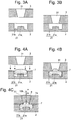
- Figs. 3A and 3B are vertical sectional views of a sample-holding section in the sample plate 1A for a solid sample.
- Figs. 4A-4C are vertical sectional views for explaining the steps of placing a sample in the sample plate 1A for a solid sample.
- Fig. 5 is a plan view of the sample plate 1A for a solid sample put in the plate holder 108 of the mass spectrometer shown in Fig. 1 , as viewed from the left side in Fig. 1 .
- the sample plate 1A for a solid sample includes a main body 2 which is substantially plate shaped and a lid 3 which is also substantially plate shaped.
- the lid 3 is connected to the main body 2 by a hinge section 22.
- the entire sample plate 1A is substantially in the form of a flat rectangular parallelepiped.
- These parts are all made of resin, such as polypropylene.
- a concave portion 21 for containing a sample is formed at a predetermined position in the main body 2.
- the concave portion 21 has a sample placement platform 21a in the form of a flat column protruding from a central area of the bottom surface of the concave portion 21.
- This sample placement platform 21a is surrounded by a groove portion 21b which is substantially ring shaped as viewed from above.
- the groove portion 21b is one level lower than the top surface of the sample placement platform 21a.
- the lid 3 has a funnel-shaped opening 31 penetrating the lid 3 in the top-to-bottom direction at a position above the concave portion 21 when the lid 3 is closed as shown in Fig. 2C .
- the inner diameter of the opening 31 on the upper side is larger than that of the same opening on the lower side.
- the inner diameter of this opening 31 on the lower side is roughly the same as the diameter of the sample placement platform 21a in the concave portion 21.
- the sample plate 1A for a solid sample is typically suitable for a measurement of a solid sample which is comparatively soft, such as a tissue section collected from a living organism.
- a procedure for setting a sample in the sample plate 1A for a solid sample is as follows: Initially, with the lid 3 sufficiently opened, a small piece of sample 7 is placed in the concave portion 21 of the main body 2 with a pair of tweezers or similar tool, as shown in Fig. 4A .
- the sample 7 should preferably have a size that is one size smaller than the concave portion 21 as viewed from above and a height that is slightly larger than the depth of the concave portion 21 at the sample placement platform 21a. Subsequently, the lid 3 is closed, as shown in Figs. 2B and 2C .
- the main body 2 and the lid 3 respectively have latch mechanisms (e.g. a claw and an opening or projection on which the claw is to be hooked) which can be engaged with each other to hold the lid 3 in the closed position.
- An operator closes the lid 3 to a position where the lid 3 is maintained in the closed state by the action of the latch mechanisms.
- the lower wall surface (the surface which comes in contact with the main body 2) surrounding the opening 31 of the lid 3 comes in contact with the sample 7, as shown in Fig. 4B , and presses the sample 7 downward. Since the groove portion 21b in the concave portion 21 is one level lower than the sample placement platform 21a, the pressed sample 7 escapes into the groove portion 21b. Meanwhile, since the opening 31 is present immediately above the sample placement platform 21a, the central portion of the sample 7 bulges upward and enters the opening 31. Thus, the sample 7 is held in a stable form, being sandwiched between the main body 2 and the lid 3.
- the operator injects a predetermined amount of solvent into the opening 31. Since the lower side of the opening is almost completely closed by the sample 7, the opening 31 effectively functions as a solvent container. That is to say, as shown in Fig. 4C , the solvent 8 will be stored above the sample 7 held on the sample placement platform 21a. Since the area which surrounds the opening 31 on the lower wall surface of the lid 3 is almost completely in contact with the sample 7 (at the site indicated by reference sign 7a in Fig. 4C ), this area exhibits a high degree of liquid tightness. Therefore, the solvent injected into the opening 31 will not leak into the concave portion 21. This reduces the amount of unnecessary use of the solvent.
- the sample plate 1A for a solid sample is put into the metallic plate holder 108.
- the plate holder 108 has an insertion slot 108b into which the sample plate 1A for a solid sample can be inserted.
- a pair of stoppers 32 extending upward from the lid 3 come in contact with the upper guides 108a on the upper side of the insertion slot 108b.
- the position where the stoppers 32 come in contact with the upper guides 108a is the correct measurement position for the sample plate 1A for a solid sample held in the plate holder 108. That is to say, by pushing the sample plate 1A for a solid sample into the insertion slot 108b until the stoppers 32 come in contact with the upper guide 108a, the sample plate 1A for a solid sample can always be set at the correct measurement position.
- the probe 106 Under the condition that the probe 106 has been correctly positioned in the X-Y plane in a manner to be described later, when the sample plate 1A for a solid sample is set at the correct measurement position in the plate holder 108 in the previously described manner, the probe 106 being lowered will be inserted into a roughly central area of the opening 31. Therefore, when the probe 106 is lowered to the lowest predetermined point as shown in Fig. 4C , the tip of the probe 106 passes through the solvent 8 and eventually pierces the sample 7. This barely causes the sample 7 to change its position, since the sample 7 is held by a sufficient pressure. The probe 106 which has pierced the sample 7 is subsequently lifted.
- a component in a sample can be satisfactorily ionized and subjected to mass spectrometry by using the sample plate 1A for a solid sample according to the present embodiment. Consequently, a high level of measurement accuracy and sensitivity can be achieved.
- the configuration of the sample-holding section shown in Figs. 3A and 3B may be appropriately modified. Modified examples of the sample-holding section are hereinafter described.
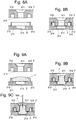
- Figs. 6A and 6B are vertical sectional views of a sample plate for solid-sample measurement which is another embodiment of the present invention.
- Figs. 7A-7C are vertical sectional views for explaining the steps of placing a sample in the sample plate shown in Figs. 6A and 6B .
- a projection 202 protruding upward in the form of a flat cylinder is formed at a predetermined position on the main body 2.
- the area surrounded by this projection 202 serves as the concave portion 201 for containing a sample.
- the lid 3 has a mating groove 302 in the form of a cylinder to be mated with the projection 202 when the lid 3 is closed.
- the portion surrounded by this mating groove 302 is a convex portion 303 to be mated with the concave portion 201.
- An opening 301 penetrating through this convex portion 303 in the top-to-bottom direction is bored at the center of the convex portion 303.
- a procedure for setting a solid sample is as follows: Initially, with the lid 3 sufficiently opened, a sample 7 is placed in the concave portion 201 of the main body 2 with a pair of tweezers or similar tool, as shown in Fig. 7A . Subsequently, the lid 3 is closed. Then, as shown in Fig. 7B , the lower surface of the convex portion 303 of the lid 3 squeezes a portion of the sample 7. Since the sample 7 is soft, a portion of the pressed sample 7 escapes into the opening 301. Consequently, the sample 7 significantly bulges within the opening 301. Thus, the sample 7 is held in a stable form, being sandwiched between the main body 2 and the lid 3.
- a solvent is injected into the opening 301, the sample plate is set in the plate holder section, and the measurement is performed.
- the lowered probe 106 pierces the sample 7 to make a trace amount of sample 7 adhere to the probe 106 and be subjected to the measurement.
- Figs. 8A and 8B are vertical sectional views of the sample-holding section in a sample plate for solid-sample measurement which is still another embodiment of the present invention which is an improved version of the sample plate for solid-sample measurement described with reference to Figs. 6A and 6B as well as Figs. 7A-7C .
- Figs. 9A-9C are vertical sectional views for explaining the steps of placing a sample in the sample plate shown in Figs. 8A and 8B .
- a projection 212 protruding upward in the form of a flat cylinder is formed at a predetermined position on the main body 2.
- the area surrounded by this projection 212 serves as the concave portion 211 for containing a sample.
- This concave portion 211 has a groove portion 213 formed roughly at the center of the bottom surface of the concave portion.
- the groove portion 213 is one level lower than the other areas. There is no specific limitation on the shape of this groove portion 213.
- the lid 3 has a ring-shaped insertion groove 312 into which the projection 212 is to be inserted when the lid 3 is closed.
- the area surrounded by this insertion groove 312 serves as the convex portion 313 to be inserted into the concave portion 211.
- An opening 311 penetrating through this convex portion 313 in the top-to-bottom direction is bored at the center of the convex portion 313.
- the width of the insertion groove 312 in the radial direction is considerably larger than that of the projection 212 in the radial direction. Therefore, when the lid 3 is closed, a ring-shaped space 214 is formed between the inner wall surface of the projection 212 and the circumferential surface of the convex portion 313, as shown in Fig. 8B .
- a procedure for setting a solid sample is as follows: Initially, with the lid 3 sufficiently opened, a sample 7 is placed in the concave portion 211 of the main body 2 with a pair of tweezers or similar tool, as shown in Fig. 9A . Subsequently, the lid 3 is closed. Then, as shown in Fig. 9B , the lower surface of the convex portion 313 of the lid 3 presses a portion of the sample 7. While a portion of this sample 7 is squeezed, the largest portion of the pressed sample 7 escapes into the outer space 214 or groove portion 213. Meanwhile, the sample 7 also bulges within the opening 311.
- the sample 7 is held in a stable form, being sandwiched between the main body 2 and the lid 3.
- a solvent is injected into the opening 311, the sample plate is set in the plate holder section, and the measurement is performed.
- the lowered probe 106 pierces the sample 7 to make a trace amount of sample 7 adhere to the probe 106 and be subjected to the measurement.
- This configuration significantly reduces the amount of squeezed sample and prevents the squeezed sample from being sputtered upward from the sample plate and scattered over the surrounding area or adhering to the operator. Therefore, for example, even if the sample is possibly contaminated with microorganisms, a high level of security can be ensured.
- Figs. 10A-10C are external views of a sample plate 1B for a liquid sample as one embodiment of the present invention, where Fig. 10A is a top view, Fig. 10B is a front view, and Fig. 10C is a side view.
- Figs. 11A-11C are diagrams for explaining the steps of adjusting the position of the probe 106 using the sample plate 1B for a liquid sample.
- the sample plate 1B for a liquid sample includes a main body 2 which is substantially plate shaped and a lid 4 which is also substantially plate shaped.
- the cover 4 is connected to the main body 2 by a hinge section 22.
- the main body 2 is completely identical to that of the sample plate 1A for a solid sample, including the shape and position of the concave portion 21. Therefore, the main body 2 is denoted by the same reference sign.
- the opening 41 formed in the lid 4 has a cylindrical shape, which is different from the shape of the opening 31 formed in the lid 3 in the sample plate 1A for a solid sample.
- the cylindrical opening 41 is configured to be combined with the concave portion 21 to form a reservoir for containing a liquid sample.
- the reservoir in the present embodiment has a considerably small capacity of 9 ⁇ L. It is naturally possible to appropriately change its capacity.
- a liquid sample In the case of a liquid sample, it is unnecessary to separate the sample plate into the main body 2 and the lid 4, since the liquid sample merely need to be injected into a reservoir which is formed when the lid 4 is closed.
- the configuration as shown in Figs. 10A-10C is adopted in the present embodiment in order to share the same configuration with the sample plate 1A for a solid sample.
- the sample plate 1B for a liquid sample has the same external shape as the sample plate 1A for a solid sample.
- the position of the openings 31 and 41 as well as those of the stoppers and the concave portion 21 are also the same.
- the sample plate 1B into which the liquid sample has been injected in the previously described manner can be put into the plate holder 108 in a similar manner to the sample plate 1A for a solid sample to perform a measurement and acquire detection signals for a component in the liquid sample
- the lowest point to which the probe 106 should be lowered in a measurement may normally be set at the same position. That is to say, it is unnecessary to change the position of the lowest point depending on whether the measurement target is a liquid sample or solid sample. In this respect, the setting of the measurement conditions and other related tasks will be simpler.
- the sample plate 1B for a liquid sample can be used not only as a sample plate; it can also be used for the positional adjustment of the probe 106 in the X-Y plane. A description concerning this point is hereinafter given with reference to Figs. 11A-11C .
- the probe 106 when a measurement is performed, the probe 106 is fitted in the probe holder 105.
- a cylindrical positioning pipe 120 is fitted in the probe holder 105 in place of the probe 106 (see Fig. 11B ).
- the positioning pipe 120 has the same outer diameter as that of the base portion of the probe 106 (i.e. the portion to be held by the probe holder 105).
- the outer diameter of the positioning pipe 120 is 1.6 mm.
- the inner diameter of the opening 41 of the sample plate 1B for a liquid sample is 2.0 mm, which is one size larger than the outer diameter of the positioning pipe 120.
- the operator With the positioning pipe 120 fitted in the probe holder 105, the operator lowers the positioning pipe 120 and adjusts the position of the probe holder 105 (and the positioning pipe 120) in each of the two directions of X and Y axes so that the lower end of the positioning pipe 120 will enter the opening 41 of the sample plate 1B for a liquid sample (see Fig. 11C ).
- the position of the probe 106 in the X-Y plane can be appropriately adjusted so that the probe 106 will be lowered into a roughly central area of the opening 41 of the sample plate 1B for a liquid sample (or sample plate 1A for a solid sample) located at the correct measurement position.
- Figs. 12A-12C are external views of a sample plate 1C for a liquid sample which is still another embodiment of the present invention, where Fig. 12A is a top view, Fig. 12B is a front view, and Fig. 12C is a side view.
- the external shape of the sample plate 1C for a liquid sample is completely identical to that of the sample plate 1B for a liquid sample.
- the present sample plate 1C for a liquid sample has three concave portions 51a, 51b and 51c formed in the main body 5, while the lid 6 has three openings 61a, 61b and 61c bored at positions immediately above the concave portions 51a, 51b and 51c, respectively.
- the concave portion 51c and the opening 61c are located at the same position as the concave portion 21 and the opening 41 in the sample plate 1B for a liquid sample as viewed from above.
- a first passage 52a is formed between the concave portion 51a and the concave portion 51c, while a second passage 52b is formed between the concave portion 51b and the concave portion 51c.
- Each of the first and second passages 52a and 52b may be a simple groove carved in the main body 5.
- a first liquid sample is injected into a reservoir formed by the concave portion 51a and the opening 61a when the lid 6 is closed, while a second liquid sample is injected into a reservoir formed by the concave portion 51b and the opening 61b.
- the first and second liquid samples respectively flow through the passages 52a and 52b into the concave portion 51c, causing a chemical reaction within the concave portion 51c.
- the flow rate (flow velocity) of the liquid sample which flows through the passage 52a or 52b can be controlled by appropriately changing the inclination, cross section and/or other parameters of the passage. This also allows for an adjustment of the rate of reaction. Additionally, an appropriate switching mechanism may be provided in each passage to change the timing of the initiation or discontinuation of the supply of a liquid sample or reagent, or to change the flow rate in the middle of the measurement.
- one sample is contained in one sample plate. It is naturally possible to design the sample plate so that it can contain a plurality of samples, as with a sample plate for matrix assisted laser desorption/ionization (MALDI). In that case, one or both of the plate holder 108 and the probe holder 105 in the mass spectrometer may be configured to be movable in the X-Y plane and allow for a sequential measurement of a plurality of samples placed at different positions in one sample plate.
- MALDI matrix assisted laser desorption/ionization
- any of the previously described sample plates consists of a main body and a lid connected by a hinge section, it is unnecessary to connect the base body and the lid.
- the entire shape (or the like) of the sample plate is not limited to a substantially flat rectangular-parallelepiped shape, but may be changed to an appropriate shape, such as a disc.
- the mass spectrometer shown in Fig. 1 is a single type quadrupole mass spectrometer, the present invention is also applicable in a different type of mass spectrometer, such as a triple quadrupole mass spectrometer or quadrupole time-of-flight (q-TOF) mass spectrometer. That is to say, as long as the mass spectrometer employs a PESI ion source, there is no specific limitation on the configuration of the mass separator and other sections located in the subsequent stages.
- q-TOF time-of-flight
Landscapes
- Chemical & Material Sciences (AREA)
- Physics & Mathematics (AREA)
- Analytical Chemistry (AREA)
- Spectroscopy & Molecular Physics (AREA)
- Health & Medical Sciences (AREA)
- Life Sciences & Earth Sciences (AREA)
- Plasma & Fusion (AREA)
- Engineering & Computer Science (AREA)
- General Health & Medical Sciences (AREA)
- Biochemistry (AREA)
- Molecular Biology (AREA)
- General Physics & Mathematics (AREA)
- Immunology (AREA)
- Pathology (AREA)
- Electrochemistry (AREA)
- Chemical Kinetics & Catalysis (AREA)
- Other Investigation Or Analysis Of Materials By Electrical Means (AREA)
- Electron Tubes For Measurement (AREA)
Abstract
Description
- The present invention relates to a sample plate for an ion source employing a probe electrospray ionization (PESI) method, as well as a mass spectrometer in which such a sample plate is used to perform a measurement.
- Various ionization methods have conventionally been proposed and put to practical use for ionizing a component in a sample prepared as a measurement target in a mass spectrometer. As a type of ionization method in which ionization is performed in an ambience of atmospheric pressure, an electrospray ionization (ESI) method is commonly known. As one of the ionization methods which employ the ESI, a PESI method has been drawing attention in recent years.
- The PESI method is a comparatively new ionization technique. As disclosed in
Patent Literature 1 orNon-Patent Literature 1, a PESI ion source includes: an electrically conductive probe having a tip with a diameter of several hundred nanometers; a position-changing unit for changing the position of one or both of the probe and a sample so as to make the sample adhere to the tip of the probe; and a high voltage generator for applying a high voltage to the probe with the sample collected on the tip of the probe. In a measurement, the position-changing unit is operated to change the position of one or both of the probe and the sample so that the tip of the probe comes in contact with or slightly pierces the sample and makes a trace amount of sample adhere to the tip surface of the probe. The position-changing unit is subsequently operated to remove the probe from the sample, and a high voltage is applied from the high-voltage generator to the probe. Then, a strong electric field acts on the sample adhered to the tip of the probe and induces the electrospray phenomenon, which causes the molecules of the components in the sample to be ionized while being released. - Since the ionization in the PESI ion source is performed in an ambience of atmospheric pressure, both a solid sample, such as a biological tissue section, and a liquid sample, such as blood, can be treated as a sample to be subjected to the measurement.
- In a mass spectrometer which uses a PESI ion source as the ion source (a mass spectrometer using a PESI ion source is hereinafter simply called the "mass spectrometer"), when a measurement for a solid sample is to be performed, it is normally the case that the sample is directly placed on a sample stage, or the sample is placed on a plate held on the sample stage. Then, the sample is pierced with the lowered probe to make the sample adhere to the tip of the probe (see
Patent Literature 2 or other related documents). - However, in the case of performing a measurement for a considerable number of samples while sequentially replacing one sample with another, a considerable amount of time and labor will be required for the replacement of the sample. There is also another problem: It is common that a mass spectrometric analysis be repeatedly performed multiple times for the same sample and the obtained mass spectrometric results are accumulated. In such an analysis, a slice of sample fresh from a living organism may change its position by a small amount and prevent the probe from piercing the same site of the sample, which lowers the reliability of the analysis. Furthermore, the PESI method normally requires a solvent in the process of ionizing the components in a solid sample. Therefore, an additional mechanism for supplying a solvent to the sample adhered to the tip of the probe is required, which makes the device more complex in structure and more expensive.
- In the case of a measurement of a liquid sample, for example, a container holding the liquid sample is placed on the sample stage, and the probe is dipped in the liquid sample in the container to make the sample adhere to the tip of the probe. In another method for making the liquid sample adhere to the tip of the sample, a capillary tube through which the liquid sample is supplied is provided so that its outlet end is located within the movable range of the probe, thereby allowing the probe to come in contact with a droplet formed at the outlet end of the capillary tube due to the supply of the liquid sample.
- Thus, there is a complete difference between a measurement for a solid sample and a measurement for a liquid sample in terms of the method for setting the sample in the device. Therefore, the measurement task will be extremely cumbersome and significantly lower the measurement efficiency if a measurement for a liquid sample is inserted into a series of measurements for a plurality of solid samples, or conversely, if a measurement for a solid sample is inserted into a series of measurements for a plurality of liquid samples.
-
- Patent Literature 1:
JP 2014-44110 A - Patent Literature 2:
WO 2016/027319 A - Non Patent Literature 1: Sen Takeda and even other authors, "Developing a Novel Cancer Diagnostic System Based on the Mass Spectrometry and Learning Machine", Shimadzu Review, Vol. 69, No. 3/4, March 2013
- The present invention has been developed to solve the previously described problems. Its primary objective is to provide a sample plate for a PESI ion source which can securely hold a solid sample, does not require an additional mechanism for supplying a solvent, and allows a measurement to be efficiently performed, as well as a mass spectrometer using such a sample plate. Another objective of the present invention is to provide a sample plate for a PESI ion source which allows a measurement to be efficiently performed for a plurality of samples even if those samples include solid samples and liquid samples, as well as a mass spectrometer using such a sample plate.
- A sample plate for a PESI ion source according to the first aspect of the present invention developed for solving the previously described problem is a sample plate for a probe electrospray ionization (PESI) ion source. The sample plate includes a substantially plate-shaped main body and a substantially plate-shaped lid configured to be put on the top surface of the main body, where:
- the main body includes a concave portion for containing a sample; and
- the lid includes a convex portion to be inserted into the concave portion when the lid is closed so as to cover the top surface of the main body, and the convex portion has an opening bored through the convex portion in a top-to-bottom direction.
- A sample plate for a PESI ion source according to the second aspect of the present invention developed for solving the previously described problem is a sample plate for a probe electro spray ionization (PESI) ion source. The sample plate includes a substantially plate-shaped main body and a substantially plate-shaped lid configured to be put on the top surface of the main body, where:
- the main body includes a concave portion for containing a sample, the concave portion having a bottom surface on which a sample placement platform one level higher than the surrounding area is formed; and
- the lid has an opening bored through the lid in a top-to-bottom direction at a position above the concave portion when the lid is closed so as to cover the top surface of the main body, where the lower side of the opening is smaller in size than the top opening of the concave portion.
- As a typical form of the sample plate for a PESI ion source according to the first or second aspect of the present invention, the sample plate may have an external shape which is substantially a flat rectangular parallelepiped when the lid is closed so as to cover the top surface of the main body.
- For example, in the case where the sample plate for a PESI ion source according to the first aspect of the present invention is used for a measurement of a solid sample which is soft to some extent, such as a biological tissue section, the sample is prepared as follows:
- With the lid of the sample plate opened, a sample of an appropriate size is placed in the concave portion of the main body. The sample should preferably have a size that is one size smaller than the opening of the concave portion as viewed from above and a height that is slightly larger than the depth of the same concave portion. After the sample is placed in the concave portion, the lid is closed. Then, the convex portion of the lid is inserted into the concave portion of the main body, with the lower surface of the convex portion coming in contact with the sample in the concave portion and squeezing the same sample. Within an area where the opening is formed in the convex portion, a portion of the sample pressed by the lower surface of the convex portion surrounding that area escapes into the same area. Thus, the sample bulges into the opening.
- Subsequently, an appropriate amount of solvent is injected (or dropped) into the opening. Since the lower side of the opening is closed by the bulging sample in the previously described manner, the opening in this state functions as a solvent reservoir. Thus, the solvent is stored in the space above the sample contained in the concave portion, being in contact with the upper surface of the same sample. The sample plate with the sample prepared in this manner is set at a predetermined position in the PESI ion source in the mass spectrometer, and the measurement is performed. The tip of the lowered probe is inserted into the opening of the lid and pierces the sample. The probe is subsequently lifted, with a trace amount of sample adhered to the tip of the probe. This sample adhered to the tip of the probe has a sufficient amount of solvent adhered, since the sample passes through the solvent during the lifting motion. In this state, a high voltage is applied to the probe, whereby the components in the sample on the tip of the probe are ionized by the electrospray phenomenon.
- In the case where a sample plate for a PESI ion source according to the second aspect of the present invention is used for a measurement of a solid sample, such as a biological tissue section, the sample is prepared as follows:
With the lid of the sample plate opened, a sample of an appropriate size is placed in the concave portion of the main body. The lower side of the opening bored in the lid is smaller in size than the top opening of the concave portion. Therefore, when the lid is closed after the sample has been placed in the concave portion, the bottom wall surface of the lid surrounding the opening comes in contact with and presses the sample contained in the concave portion. Since the circumferential portion of the bottom surface of the concave portion is in the form of a groove which is one level lower than the sample placement platform, a portion of the pressed sample escapes into this groove portion. Meanwhile, the sample within the opening does not receive the pressure. The lower side of this sample is supported by the sample placement platform. Therefore, a portion of the sample bulges into the opening. By allowing a portion of the pressed sample to escape into the groove portion, the present sample plate makes an appropriate amount of sample bulge into the opening of the lid while preventing, for example, the squeezed sample from being sputtered upward from the sample plate. - Subsequently, as with the sample plate according to the first aspect of the present invention, an appropriate amount of solvent is injected (or dropped) into the opening. Thus, the solvent is stored in the space above the sample held on the sample placement platform, being in contact with the same sample. The sample plate with the sample prepared in this manner is set at a predetermined position in the PESI ion source in the mass spectrometer, and the measurement is performed. The tip of the lowered probe is inserted into the through hole of the lid and pierces the sample. The probe is subsequently lifted, with a trace amount of sample adhered to the tip of the probe. This sample adhered to the tip of the probe has a sufficient amount of solvent adhered, since the sample passes through the solvent during the lifting motion. In this state, a high voltage is applied to the probe, whereby the components in the sample on the tip of the probe are ionized by the electrospray phenomenon.
- In a preferable mode of the sample plate for an PESI ion source according to the first aspect of the present invention, a groove is formed in one or both of the concave portion in the main body and the convex portion on the lid so that a space into which a portion of the sample is allowed to escape is formed within the concave portion when the lid is closed so as to cover the top surface of the main body.
- According to this configuration, a space into which a portion of the sample can escape, or in other words, a space into which a portion of the sample can move while changing its shape, is also present in the sample plate for a PESI ion source according to the first aspect of the present invention, as with the sample plate for a PESI ion source according to the second aspect of the present invention. Therefore, the present sample plate can make an appropriate amount of sample bulge into the opening of the lid while preventing the squeezed sample from being sputtered upward from the sample plate, for example.
- The sample plate for a PESI ion source according to the first or second aspect of the present invention allows a liquid sample to be injected into the opening and the concave portion when the lid is closed, instead of placing a solid sample in the concave portion. In that case, a certain minimum amount of liquid sample needs to be injected in order to perform the measurement with a high level of accuracy and sensitivity.
- In view of this requirement, a sample plate for a PESI ion source according to a different aspect of the present invention has substantially the same external shape as the sample plate for a PESI ion source according to the first or second aspect of the present invention, and includes:
a main body in which a concave portion that is identical in shape to the previously described concave portion is formed, and a substantially plate-shaped lid in which a cylindrical opening that is identical in size to the top opening of the concave portion is formed. - In the sample plate for a PESI ion source according to this aspect of the present invention, the amount of liquid that can be stored in the opening and the concave portion can be increased by changing the size of the opening bored in the lid. Therefore, a sufficient amount of liquid sample can be secured for a measurement, and a sample plate that is suited for the measurement of a liquid sample can be obtained.
- By having substantially the same external shape as the sample plate for a PESI ion source according to any of the previously described aspects of the present invention which is mainly used for the measurement of a solid sample, any of those sample plates can be put into a plate holder section in the PESI ion source. Accordingly, it is possible to perform the measurement for a plurality of samples while sequentially replacing one sample with another a measurement regardless of whether the sample is a solid sample or liquid sample, so that the measurement efficiency can be dramatically improved. Since the main bodies of the sample plates are common to both the measurement of a solid sample and that of a liquid sample, the lowest point to which the probe should be lowered in the measurement can be set at the same position for both the measurement of a solid sample and that of a liquid sample. This facilitates the control of the probe. The common design of the main bodies of the sample plates for both the measurement of a solid sample and that of a liquid sample also reduces the manufacturing cost of the sample plate.
- In the sample plate for a PESI ion source according to the aforementioned different aspect of the present invention, i.e. in the sample plate for the measurement of a liquid sample, the opening may preferably be configured to have an inner diameter which is a predetermined amount larger than the outer diameter of a base portion of the probe in a PESI ion source in which the sample plate is to be used.
- In a PESI ion source, the position of the probe within a plane which is orthogonal to the lowering direction (vertical direction) needs to be adjusted so that the lowered probe will assuredly come in contact with the sample prepared on the sample plate. The sample plate having the previously described configuration helps this task as follows: In place of the probe, a cylindrical pipe having the same outer diameter as the base portion of the probe is fitted in the probe holder which holds the base portion of the probe in the PESI ion source, and the positional adjustment is performed so that the cylindrical pipe will correctly enter the opening of the sample plate when the pipe is lowered. As a result, the position of the probe is properly adjusted. Thus, the positional adjustment of the probe can be correctly and easily performed by using the sample plate for a measurement of a sample.
- A sample plate for a PESI ion source according to still another aspect of the present invention is a sample plate for a probe electrospray ionization (PESI) ion source, including a substantially plate-shaped base body in which a plurality of concave portions each of which is capable of containing a liquid are formed, where each of the concave portions has a passage formed in the base body so as to allow a liquid to flow between the concave portion concerned and at least one of the other concave portions.
- In the sample plate for a PESI ion source according to this aspect of the present invention, a liquid can flow from one concave portion to another through a passage. Therefore, for example, a liquid sample, reagent or similar substance can be gradually supplied from one concave portion through the passage to another liquid sample contained in another concave portion, so as to gradually promote a chemical reaction and perform a continuous measurement during the reaction process. As another example, a plurality of different liquid samples can be supplied from a plurality of concave portions through their respective passages to another concave portion to induce a reaction in this concave portion. The flow rate (flow velocity) can be controlled by the inclination, cross section and other parameters of the passage. This allows for the control of the reaction rate or other conditions of the reaction induced in the previously described manner.
- A switching mechanism may be provided in the passage for some purposes, e.g. in order to mix a specific sample or reagent at a specific timing, or discontinue the mixing. Such a switching mechanism may preferably be configured to be mechanically or electrically operable from the outside.
- A mass spectrometer according to the present invention includes a PESI ion source which includes a plate holder section configured to hold a sample plate for a PESI ion source according to any of the previously described aspects of the present invention, the PESI ion source configured to collect a sample from the sample plate held by the plate holder section onto the tip of a probe and to ionize a component in the collected sample.
- In the mass spectrometer according to the present invention, various samples can be successively subjected to a measurement, regardless of whether the sample is a solid sample or liquid samples, by sequentially putting one sample plate after another in the plate holder section. A handling device for attaching and removing a sample plate to and from the plate holder section may be provided to automatically perform a continuous measurement for a plurality of samples. The use of the sample plates having substantially the same external shape regardless of the type of sample is beneficial for the attachment and removal of the sample plate by such a handling device.
- A sample plate for a PESI ion source according to the present invention can securely hold a biological tissue section or similar solid sample and allow a probe to pierce the sample. Furthermore, a solvent can be made to adhere to the solid sample in the process of lowering and lifting the probe. Accordingly, for example, when a measurement is performed multiple times for the same sample, the sample can be collected from almost the same site, and the solvent can be assuredly adhered to the sample to perform satisfactory ionization. Consequently, the accuracy and sensitivity of the measurement will be improved. Since there is no need to additionally provide a mechanism for supplying a solvent to the sample, the PESI ion source can be simpler in structure, which lowers the cost of the device. Having samples prepared beforehand in the sample plates facilitates the task of replacing the samples in the middle of the measurement. This helps improve the measurement efficiency.
-
-
Fig. 1 is a schematic configuration diagram of one embodiment of a mass spectrometer using a sample plate according to the present invention. -
Figs. 2A-2D are external views of a sample plate for solid-sample measurement as one embodiment of the present invention, whereFig. 2A is a top view,Fig. 2B is a front view,Fig. 2C is a side view, andFig. 2D is a side view with the lid opened. -
Figs. 3A and 3B are vertical sectional views of a sample-holding section in the sample plate according to the present embodiment. -
Fig. 4A-4C are vertical sectional views for explaining the steps of placing a sample in the sample plate according to the present embodiment. -
Fig. 5 is a plan view of the sample plate according to the present embodiment put in a plate holder of the mass spectrometer according to the present embodiment. -
Figs. 6A and 6B are vertical sectional views of the sample-holding section in a sample plate for solid-sample measurement which is another embodiment of the present invention. -
Figs. 7A-7C are vertical sectional views for explaining the steps of placing a sample in the sample plate shown inFigs. 6A and 6B . -
Figs. 8A and 8B are vertical sectional views of the sample-holding section in a sample plate for solid-sample measurement which is still another embodiment of the present invention. -
Figs. 9A-9C are vertical sectional views for explaining the steps of placing a sample in the sample plate shown inFigs. 8A and 8B . -
Figs. 10A-10C are external views of a sample plate for liquid-sample measurement which is another embodiment of the present invention, whereFig. 10A is a top view,Fig. 10B is a front view, andFig. 10C is a side view. -
Figs. 11A-11C are diagrams for explaining the steps of adjusting the position of the probe using the sample plate shown inFigs. 10A-10C . -
Figs. 12A-12C are external views of a sample plate for liquid-sample measurement which is still another embodiment of the present invention, whereFig. 12A is a top view,Fig. 12B is a front view, andFig. 12C is a side view. - One embodiment of the mass spectrometer in which a sample plate according to the present invention is used is hereinafter described.
Fig. 1 is a configuration diagram showing the main components of the mass spectrometer according to the present embodiment. - As shown in
Fig. 1 , the present mass spectrometer has the configuration of a multistage differential pumping system including anionization chamber 101 for ionizing a component in a sample in an ambience of atmospheric pressure and ananalysis chamber 104 for performing the mass spectrometry and detection of ions in a high-vacuum ambience, with a plurality of (in the present embodiment, two)intermediate vacuum chambers - Within the
ionization chamber 101 maintained at substantially atmospheric pressure, aplate holder 108 for holding asample plate 1A (or 1B or 1C, which will be described later) is provided. Ametallic probe 106 held by aprobe holder 105 and extending in the vertical direction (Z-axis direction) is located above theplate holder 108. Theprobe holder 105 with theprobe 106 fitted can be driven in the vertical direction (Z-axis direction) by aprobe drive mechanism 107 including a motor, speed reducer and other elements. Theprobe 106 and theprobe holder 105 can also be manually driven in each of the two directions of X and Y axes by means of a rack and pinion or similar mechanism (not shown). This allows for the positional adjustment of theprobe 106 in the X-Y plane. Additionally, a high voltage of up to several kV (with a switchable polarity) can be applied from a high-voltage power source (not shown) to theprobe 106. - The inner space of the
ionization chamber 101 communicates with that of the firstintermediate vacuum chamber 102 through a thincapillary tube 110. Due to the pressure difference between the two open ends of thecapillary tube 110, the gas within theionization chamber 101 is drawn into the firstintermediate vacuum chamber 102 through thecapillary tube 110. The firstintermediate vacuum chamber 102 contains an ion guide 111 composed of a plurality of plate electrodes arranged along the ion beam axis C and surrounding the same axis C. The inner space of the firstintermediate vacuum chamber 102 communicates with that of the secondintermediate vacuum chamber 103 through a small hole formed at the apex of askimmer 112. The secondintermediate vacuum chamber 103 contains anoctapole ion guide 113 having eight rod electrodes arranged around the ion beam axis C. Theanalysis chamber 104 contains a quadrupolemass filter 114 having four rod electrodes arranged around the ion beam axis C, as well as anion detector 115. - As will be described later in detail, the
sample plate 1A contains a sample to be subjected to a measurement. When theprobe 106 is lowered to a predetermined position by theprobe drive mechanism 107, a trace amount of sample adheres to the tip of theprobe 106. After theprobe 106 is lifted to a predetermined position, a high voltage is applied to theprobe 106. This voltage creates an electric field concentrated on the tip of theprobe 106, inducing the electrospray phenomenon by which the components in the sample adhered to theprobe 106 are ionized. The generated ions are drawn into thecapillary tube 110 due to the pressure difference mentioned earlier, and are sequentially transported through the firstintermediate vacuum chamber 102 and the secondintermediate vacuum chamber 103 into theanalysis chamber 104 due to the effect of the electric fields respectively created by the ion guides 111 and 113. Those ions are introduced into the quadrupolemass filter 114. Only an ion having a specific mass-to-charge ratio corresponding to a voltage applied to the rod electrodes of the quadrupolemass filter 114 is allowed to pass through thisfilter 114 and reach theion detector 115. Theion detector 115 generates a detection signal corresponding to the amount of ions which have reached the detector. - For example, a detection signal corresponding to the amount of target component in a sample can be obtained by setting the voltage applied to the rod electrodes of the quadruple
mass filter 114 so that only an ion originating from the target component will be allowed to pass through the quadrupolemass filter 114. - One embodiment of the sample plate according to the present invention is hereinafter described with reference to
Figs. 2A-5 . -
Figs. 2A-2D are external views of thesample plate 1A for a solid sample as one embodiment of the present invention, whereFig. 2A is a top view,Fig. 2B is a front view,Fig. 2C is a side view, andFig. 2D is a side view with the lid opened.Figs. 3A and 3B are vertical sectional views of a sample-holding section in thesample plate 1A for a solid sample.Figs. 4A-4C are vertical sectional views for explaining the steps of placing a sample in thesample plate 1A for a solid sample.Fig. 5 is a plan view of thesample plate 1A for a solid sample put in theplate holder 108 of the mass spectrometer shown inFig. 1 , as viewed from the left side inFig. 1 . - As shown in
Figs. 2A-2D , thesample plate 1A for a solid sample includes amain body 2 which is substantially plate shaped and alid 3 which is also substantially plate shaped. Thelid 3 is connected to themain body 2 by ahinge section 22. When thelid 3 is closed so as to cover the top surface of themain body 2, theentire sample plate 1A is substantially in the form of a flat rectangular parallelepiped. These parts are all made of resin, such as polypropylene. - A
concave portion 21 for containing a sample (normally, a solid sample) is formed at a predetermined position in themain body 2. As shown inFigs. 3A and 3B , theconcave portion 21 has asample placement platform 21a in the form of a flat column protruding from a central area of the bottom surface of theconcave portion 21. Thissample placement platform 21a is surrounded by agroove portion 21b which is substantially ring shaped as viewed from above. Thegroove portion 21b is one level lower than the top surface of thesample placement platform 21a. On the other hand, thelid 3 has a funnel-shapedopening 31 penetrating thelid 3 in the top-to-bottom direction at a position above theconcave portion 21 when thelid 3 is closed as shown inFig. 2C . The inner diameter of theopening 31 on the upper side is larger than that of the same opening on the lower side. The inner diameter of thisopening 31 on the lower side is roughly the same as the diameter of thesample placement platform 21a in theconcave portion 21. - The
sample plate 1A for a solid sample is typically suitable for a measurement of a solid sample which is comparatively soft, such as a tissue section collected from a living organism. A procedure for setting a sample in thesample plate 1A for a solid sample is as follows: Initially, with thelid 3 sufficiently opened, a small piece ofsample 7 is placed in theconcave portion 21 of themain body 2 with a pair of tweezers or similar tool, as shown inFig. 4A . Thesample 7 should preferably have a size that is one size smaller than theconcave portion 21 as viewed from above and a height that is slightly larger than the depth of theconcave portion 21 at thesample placement platform 21a. Subsequently, thelid 3 is closed, as shown inFigs. 2B and 2C . - Though not shown in the figures, the
main body 2 and thelid 3 respectively have latch mechanisms (e.g. a claw and an opening or projection on which the claw is to be hooked) which can be engaged with each other to hold thelid 3 in the closed position. An operator closes thelid 3 to a position where thelid 3 is maintained in the closed state by the action of the latch mechanisms. - When the
lid 3 is closed, the lower wall surface (the surface which comes in contact with the main body 2) surrounding theopening 31 of thelid 3 comes in contact with thesample 7, as shown inFig. 4B , and presses thesample 7 downward. Since thegroove portion 21b in theconcave portion 21 is one level lower than thesample placement platform 21a, the pressedsample 7 escapes into thegroove portion 21b. Meanwhile, since theopening 31 is present immediately above thesample placement platform 21a, the central portion of thesample 7 bulges upward and enters theopening 31. Thus, thesample 7 is held in a stable form, being sandwiched between themain body 2 and thelid 3. - After the
lid 3 is closed, the operator injects a predetermined amount of solvent into theopening 31. Since the lower side of the opening is almost completely closed by thesample 7, theopening 31 effectively functions as a solvent container. That is to say, as shown inFig. 4C , the solvent 8 will be stored above thesample 7 held on thesample placement platform 21a. Since the area which surrounds theopening 31 on the lower wall surface of thelid 3 is almost completely in contact with the sample 7 (at the site indicated byreference sign 7a inFig. 4C ), this area exhibits a high degree of liquid tightness. Therefore, the solvent injected into theopening 31 will not leak into theconcave portion 21. This reduces the amount of unnecessary use of the solvent. - After the solvent is injected into the
opening 31 in the previously described manner, thesample plate 1A for a solid sample is put into themetallic plate holder 108. As shown inFig. 5 , theplate holder 108 has aninsertion slot 108b into which thesample plate 1A for a solid sample can be inserted. As thesample plate 1A for a solid sample is inserted into thisinsertion slot 108b, a pair ofstoppers 32 extending upward from thelid 3 come in contact with theupper guides 108a on the upper side of theinsertion slot 108b. The position where thestoppers 32 come in contact with theupper guides 108a is the correct measurement position for thesample plate 1A for a solid sample held in theplate holder 108. That is to say, by pushing thesample plate 1A for a solid sample into theinsertion slot 108b until thestoppers 32 come in contact with theupper guide 108a, thesample plate 1A for a solid sample can always be set at the correct measurement position. - Under the condition that the
probe 106 has been correctly positioned in the X-Y plane in a manner to be described later, when thesample plate 1A for a solid sample is set at the correct measurement position in theplate holder 108 in the previously described manner, theprobe 106 being lowered will be inserted into a roughly central area of theopening 31. Therefore, when theprobe 106 is lowered to the lowest predetermined point as shown inFig. 4C , the tip of theprobe 106 passes through the solvent 8 and eventually pierces thesample 7. This barely causes thesample 7 to change its position, since thesample 7 is held by a sufficient pressure. Theprobe 106 which has pierced thesample 7 is subsequently lifted. During this motion, the trace amount of sample adhered to the tip of theprobe 106 passes through the solvent 8. Thus, a sufficient amount of solvent adheres to the trace amount of sample which has been adhered to the tip of theprobe 106. After theprobe 106 is lifted to a predetermined position, a high voltage is applied to theprobe 106, whereupon a considerable number of fine electrically charged droplets are ejected from the sample, whereby the components in the sample are satisfactorily ionized. - As described so far, a component in a sample can be satisfactorily ionized and subjected to mass spectrometry by using the
sample plate 1A for a solid sample according to the present embodiment. Consequently, a high level of measurement accuracy and sensitivity can be achieved. - In the
sample plate 1A for a solid sample according to the previously described embodiment, the configuration of the sample-holding section shown inFigs. 3A and 3B may be appropriately modified. Modified examples of the sample-holding section are hereinafter described. -
Figs. 6A and 6B are vertical sectional views of a sample plate for solid-sample measurement which is another embodiment of the present invention.Figs. 7A-7C are vertical sectional views for explaining the steps of placing a sample in the sample plate shown inFigs. 6A and 6B . - As shown in
Fig. 6A , aprojection 202 protruding upward in the form of a flat cylinder is formed at a predetermined position on themain body 2. The area surrounded by thisprojection 202 serves as theconcave portion 201 for containing a sample. On the other hand, as shown inFig. 6B , thelid 3 has amating groove 302 in the form of a cylinder to be mated with theprojection 202 when thelid 3 is closed. The portion surrounded by thismating groove 302 is aconvex portion 303 to be mated with theconcave portion 201. Anopening 301 penetrating through thisconvex portion 303 in the top-to-bottom direction is bored at the center of theconvex portion 303. - A procedure for setting a solid sample, such as a biological tissue section, is as follows: Initially, with the
lid 3 sufficiently opened, asample 7 is placed in theconcave portion 201 of themain body 2 with a pair of tweezers or similar tool, as shown inFig. 7A . Subsequently, thelid 3 is closed. Then, as shown inFig. 7B , the lower surface of theconvex portion 303 of thelid 3 squeezes a portion of thesample 7. Since thesample 7 is soft, a portion of the pressedsample 7 escapes into theopening 301. Consequently, thesample 7 significantly bulges within theopening 301. Thus, thesample 7 is held in a stable form, being sandwiched between themain body 2 and thelid 3. After that, similar to the previous embodiment, a solvent is injected into theopening 301, the sample plate is set in the plate holder section, and the measurement is performed. In the measurement, as shown inFig. 7C , the loweredprobe 106 pierces thesample 7 to make a trace amount ofsample 7 adhere to theprobe 106 and be subjected to the measurement. -
Figs. 8A and 8B are vertical sectional views of the sample-holding section in a sample plate for solid-sample measurement which is still another embodiment of the present invention which is an improved version of the sample plate for solid-sample measurement described with reference toFigs. 6A and 6B as well asFigs. 7A-7C .Figs. 9A-9C are vertical sectional views for explaining the steps of placing a sample in the sample plate shown inFigs. 8A and 8B . In the case of the sample plate for solid-sample measurement described with reference toFigs. 6A and 6B as well asFigs. 7A-7C , there is practically no space into which the sample pressed by theconvex portion 303 can escape when thelid 3 is closed, so that the pressed sample will be squeezed. By comparison, the sample plate for solid-sample measurement shown inFigs. 8A and 8B as well asFigs. 9A-9C has a space into which the pressed sample can escape. - As shown in
Fig. 8A , aprojection 212 protruding upward in the form of a flat cylinder is formed at a predetermined position on themain body 2. The area surrounded by thisprojection 212 serves as theconcave portion 211 for containing a sample. Thisconcave portion 211 has agroove portion 213 formed roughly at the center of the bottom surface of the concave portion. Thegroove portion 213 is one level lower than the other areas. There is no specific limitation on the shape of thisgroove portion 213. On the other hand, as shown inFig. 8B , thelid 3 has a ring-shapedinsertion groove 312 into which theprojection 212 is to be inserted when thelid 3 is closed. The area surrounded by thisinsertion groove 312 serves as theconvex portion 313 to be inserted into theconcave portion 211. Anopening 311 penetrating through thisconvex portion 313 in the top-to-bottom direction is bored at the center of theconvex portion 313. The width of theinsertion groove 312 in the radial direction is considerably larger than that of theprojection 212 in the radial direction. Therefore, when thelid 3 is closed, a ring-shapedspace 214 is formed between the inner wall surface of theprojection 212 and the circumferential surface of theconvex portion 313, as shown inFig. 8B . - A procedure for setting a solid sample, such as a biological tissue section, is as follows: Initially, with the
lid 3 sufficiently opened, asample 7 is placed in theconcave portion 211 of themain body 2 with a pair of tweezers or similar tool, as shown inFig. 9A . Subsequently, thelid 3 is closed. Then, as shown inFig. 9B , the lower surface of theconvex portion 313 of thelid 3 presses a portion of thesample 7. While a portion of thissample 7 is squeezed, the largest portion of the pressedsample 7 escapes into theouter space 214 orgroove portion 213. Meanwhile, thesample 7 also bulges within theopening 311. Thus, thesample 7 is held in a stable form, being sandwiched between themain body 2 and thelid 3. After that, similar to the previous embodiment, a solvent is injected into theopening 311, the sample plate is set in the plate holder section, and the measurement is performed. In the measurement, as shown inFig. 9C , the loweredprobe 106 pierces thesample 7 to make a trace amount ofsample 7 adhere to theprobe 106 and be subjected to the measurement. - This configuration significantly reduces the amount of squeezed sample and prevents the squeezed sample from being sputtered upward from the sample plate and scattered over the surrounding area or adhering to the operator. Therefore, for example, even if the sample is possibly contaminated with microorganisms, a high level of security can be ensured.
- Subsequently, a sample plate for a liquid sample which is still another embodiment of the sample plate according to the present invention is described with reference to
Figs. 10A-10C and Figs. 11A-11C . -
Figs. 10A-10C are external views of asample plate 1B for a liquid sample as one embodiment of the present invention, whereFig. 10A is a top view,Fig. 10B is a front view, andFig. 10C is a side view.Figs. 11A-11C are diagrams for explaining the steps of adjusting the position of theprobe 106 using thesample plate 1B for a liquid sample. - Similar to the
sample plate 1A for a solid sample, thesample plate 1B for a liquid sample includes amain body 2 which is substantially plate shaped and alid 4 which is also substantially plate shaped. Thecover 4 is connected to themain body 2 by ahinge section 22. Themain body 2 is completely identical to that of thesample plate 1A for a solid sample, including the shape and position of theconcave portion 21. Therefore, themain body 2 is denoted by the same reference sign. On the other hand, theopening 41 formed in thelid 4 has a cylindrical shape, which is different from the shape of theopening 31 formed in thelid 3 in thesample plate 1A for a solid sample. Thecylindrical opening 41 is configured to be combined with theconcave portion 21 to form a reservoir for containing a liquid sample. The reservoir in the present embodiment has a considerably small capacity of 9 µL. It is naturally possible to appropriately change its capacity. - In the case of a liquid sample, it is unnecessary to separate the sample plate into the
main body 2 and thelid 4, since the liquid sample merely need to be injected into a reservoir which is formed when thelid 4 is closed. However, the configuration as shown inFigs. 10A-10C is adopted in the present embodiment in order to share the same configuration with thesample plate 1A for a solid sample. Thesample plate 1B for a liquid sample has the same external shape as thesample plate 1A for a solid sample. The position of theopenings concave portion 21 are also the same. Therefore, thesample plate 1B into which the liquid sample has been injected in the previously described manner can be put into theplate holder 108 in a similar manner to thesample plate 1A for a solid sample to perform a measurement and acquire detection signals for a component in the liquid sample - Since the
main body 2 of thesample plate 1B for a liquid sample is completely identical to that of thesample plate 1A for a solid sample, the lowest point to which theprobe 106 should be lowered in a measurement may normally be set at the same position. That is to say, it is unnecessary to change the position of the lowest point depending on whether the measurement target is a liquid sample or solid sample. In this respect, the setting of the measurement conditions and other related tasks will be simpler. - The
sample plate 1B for a liquid sample can be used not only as a sample plate; it can also be used for the positional adjustment of theprobe 106 in the X-Y plane. A description concerning this point is hereinafter given with reference toFigs. 11A-11C . - As shown in
Fig. 11A , when a measurement is performed, theprobe 106 is fitted in theprobe holder 105. When the positional adjustment of theprobe 106 is performed, acylindrical positioning pipe 120 is fitted in theprobe holder 105 in place of the probe 106 (seeFig. 11B ). Thepositioning pipe 120 has the same outer diameter as that of the base portion of the probe 106 (i.e. the portion to be held by the probe holder 105). In the present example, the outer diameter of thepositioning pipe 120 is 1.6 mm. On the other hand, the inner diameter of theopening 41 of thesample plate 1B for a liquid sample is 2.0 mm, which is one size larger than the outer diameter of thepositioning pipe 120. With thepositioning pipe 120 fitted in theprobe holder 105, the operator lowers thepositioning pipe 120 and adjusts the position of the probe holder 105 (and the positioning pipe 120) in each of the two directions of X and Y axes so that the lower end of thepositioning pipe 120 will enter theopening 41 of thesample plate 1B for a liquid sample (seeFig. 11C ). - Thus, the position of the
probe 106 in the X-Y plane can be appropriately adjusted so that theprobe 106 will be lowered into a roughly central area of theopening 41 of thesample plate 1B for a liquid sample (orsample plate 1A for a solid sample) located at the correct measurement position. -
Figs. 12A-12C are external views of a sample plate 1C for a liquid sample which is still another embodiment of the present invention, whereFig. 12A is a top view,Fig. 12B is a front view, andFig. 12C is a side view. - The external shape of the sample plate 1C for a liquid sample is completely identical to that of the
sample plate 1B for a liquid sample. The present sample plate 1C for a liquid sample has threeconcave portions main body 5, while thelid 6 has threeopenings concave portions concave portion 51c and theopening 61c are located at the same position as theconcave portion 21 and theopening 41 in thesample plate 1B for a liquid sample as viewed from above. Afirst passage 52a is formed between theconcave portion 51a and theconcave portion 51c, while asecond passage 52b is formed between theconcave portion 51b and theconcave portion 51c. Each of the first andsecond passages main body 5. - In the present sample plate 1C for a liquid sample, a first liquid sample is injected into a reservoir formed by the
concave portion 51a and theopening 61a when thelid 6 is closed, while a second liquid sample is injected into a reservoir formed by theconcave portion 51b and theopening 61b. The first and second liquid samples respectively flow through thepassages concave portion 51c, causing a chemical reaction within theconcave portion 51c. By putting this sample plate 1C for a liquid sample in theplate holder 108 and repeating a measurement for a certain period of time, a real-time measurement for a sample component which changes with the progress of the reaction can be performed. - The flow rate (flow velocity) of the liquid sample which flows through the
passage - In any of the previously described embodiments, one sample is contained in one sample plate. It is naturally possible to design the sample plate so that it can contain a plurality of samples, as with a sample plate for matrix assisted laser desorption/ionization (MALDI). In that case, one or both of the
plate holder 108 and theprobe holder 105 in the mass spectrometer may be configured to be movable in the X-Y plane and allow for a sequential measurement of a plurality of samples placed at different positions in one sample plate. - Any of the previously described embodiments and their modified examples is a mere example of the present invention, and any change, modification or addition appropriately made within the spirit of the present invention will evidently fall within the scope of claims of the present application.
- For example, although any of the previously described sample plates consists of a main body and a lid connected by a hinge section, it is unnecessary to connect the base body and the lid. The entire shape (or the like) of the sample plate is not limited to a substantially flat rectangular-parallelepiped shape, but may be changed to an appropriate shape, such as a disc.
- Although the mass spectrometer shown in
Fig. 1 is a single type quadrupole mass spectrometer, the present invention is also applicable in a different type of mass spectrometer, such as a triple quadrupole mass spectrometer or quadrupole time-of-flight (q-TOF) mass spectrometer. That is to say, as long as the mass spectrometer employs a PESI ion source, there is no specific limitation on the configuration of the mass separator and other sections located in the subsequent stages. -
- 1A...
- Sample Plate for Solid Sample
- 1B, 1C ...
- Sample Plate for Liquid Sample
- 2, 5 ...
- Main Body
- 21, 51a, 51b, 51c, 201, 211 ...
- Concave Portion
- 21a ...
- Sample Placement Platform
- 21b, 213 ...
- Groove Portion
- 22 ...
- Hinge Section
- 202, 212 ...
- Projection
- 214 ...
- Space
- 3, 4, 6 ...
- Lid
- 31, 41, 61a, 61b, 61c, 301, 311 ...
- Opening
- 302 ...
- Mating Groove
- 303, 313 ...
- Convex Portion
- 312 ...
- Insertion Groove
- 32 ...
- Stopper
- 52a ...
- First Passage
- 52b ...
- Second Passage
- 7 ...
- Sample (Solid Sample)
- 8 ...
- Solvent
- 101 ...
- Ionization Chamber
- 102 ...
- First Intermediate Vacuum Chamber
- 103 ...
- Second Intermediate Vacuum Chamber
- 104 ...
- Analysis Chamber
- 105 ...
- Probe Holder
- 106 ...
- Probe
- 107 ...
- Probe Drive Mechanism
- 108 ...
- Plate Holder
- 108a ...
- Upper Guide
- 108b ...
- Insertion Slot
- 110 ...
- Capillary Tube
- 111, 113 ...
- Ion Guide
- 112 ...
- Skimmer
- 114 ...
- Quadrupole Mass Filter
- 115 ...
- Ion Detector
- 120 ...
- Positioning Pipe
Claims (7)
- A sample plate for a probe electrospray ionization (PESI) ion source, comprising:
a substantially plate-shaped main body and a substantially plate-shaped lid configured to be put on a top surface of the main body,
wherein:the main body includes a concave portion for containing a sample; andthe lid includes a convex portion to be inserted into the concave portion when the lid is closed so as to cover the top surface of the main body, and the convex portion has an opening bored through the convex portion in a top-to-bottom direction. - The sample plate for a PESI ion source according to claim 1, wherein:
a groove is formed in one or both of the concave portion in the main body and the convex portion on the lid so that a space into which a portion of the sample is allowed to escape is formed within the concave portion when the lid is closed so as to cover the top surface of the main body. - A sample plate for a probe electrospray ionization (PESI) ion source, comprising:
a substantially plate-shaped main body and a substantially plate-shaped lid configured to be put on the top surface of the main body,
wherein:the main body includes a concave portion for containing a sample, the concave portion having a bottom surface on which a sample placement platform one level higher than a surrounding area is formed; andthe lid has an opening bored through the lid in a top-to-bottom direction at a position above the concave portion when the lid is closed so as to cover the top surface of the main body, where a lower side of the opening is smaller in size than a top opening of the concave portion. - A sample plate for a PESI ion source having substantially a same external shape as the sample plate for a PESI ion source according to one of claims 1-3, comprising:
a main body in which a concave portion that is identical in shape to the aforementioned concave portion is formed, and a substantially plate-shaped lid in which a cylindrical opening that is identical in size to the top opening of the concave portion is formed. - The sample plate for a PESI ion source according to claim 4, wherein:
the opening has an inner diameter which is a predetermined amount larger than an outer diameter of a base portion of a probe in a PESI ion source in which the sample plate is to be used. - A sample plate for a probe electrospray ionization (PESI) ion source, comprising:
a substantially plate-shaped base body in which a plurality of concave portions each of which is capable of containing a liquid are formed, where each of the concave portions has a passage formed in the base body so as to allow a liquid to flow between the concave portion concerned and at least one of the other concave portions. - A mass spectrometer, comprising a PESI ion source which includes a plate holder section configured to hold a sample plate for a PESI ion source according to one of claims 1-6, the PESI ion source configured to collect a sample from the sample plate held by the plate holder section onto a tip of a probe and to ionize a component in the collected sample.
Applications Claiming Priority (1)
| Application Number | Priority Date | Filing Date | Title |
|---|---|---|---|
| PCT/JP2017/020253 WO2018220742A1 (en) | 2017-05-31 | 2017-05-31 | Sample plate for pesi ion source and mass spectrometer using said sample plate |
Publications (3)
| Publication Number | Publication Date |
|---|---|
| EP3633365A1 true EP3633365A1 (en) | 2020-04-08 |
| EP3633365A4 EP3633365A4 (en) | 2020-10-07 |
| EP3633365B1 EP3633365B1 (en) | 2023-02-22 |
Family
ID=64454668
Family Applications (1)
| Application Number | Title | Priority Date | Filing Date |
|---|---|---|---|
| EP17911536.5A Active EP3633365B1 (en) | 2017-05-31 | 2017-05-31 | Sample plate for pesi ion source and mass spectrometer using said sample plate |
Country Status (6)
| Country | Link |
|---|---|
| US (1) | US11101125B2 (en) |
| EP (1) | EP3633365B1 (en) |
| JP (1) | JP6891953B2 (en) |
| CN (1) | CN110603440B (en) |
| TW (1) | TWI684761B (en) |
| WO (1) | WO2018220742A1 (en) |
Families Citing this family (3)
| Publication number | Priority date | Publication date | Assignee | Title |
|---|---|---|---|---|
| CN112243496B (en) * | 2018-05-31 | 2025-01-07 | 株式会社岛津制作所 | Probe Electrospray Ionization Mass Spectrometry |
| CN111370290B (en) * | 2020-04-10 | 2025-03-25 | 西北核技术研究院 | Sampling type fission ionization chamber and method for measuring total number of fissions based on the same |
| US12476099B2 (en) * | 2020-04-24 | 2025-11-18 | Shimadzu Corporation | Ion analyzer |
Family Cites Families (21)
| Publication number | Priority date | Publication date | Assignee | Title |
|---|---|---|---|---|
| JPH07260646A (en) * | 1994-03-17 | 1995-10-13 | Nikon Corp | Sample container |
| US5872010A (en) | 1995-07-21 | 1999-02-16 | Northeastern University | Microscale fluid handling system |
| US5716825A (en) | 1995-11-01 | 1998-02-10 | Hewlett Packard Company | Integrated nucleic acid analysis system for MALDI-TOF MS |
| US5705813A (en) * | 1995-11-01 | 1998-01-06 | Hewlett-Packard Company | Integrated planar liquid handling system for maldi-TOF MS |
| US6391241B1 (en) * | 1997-06-06 | 2002-05-21 | Corning Incorporated | Method of manufacture for a multiwell plate and/or filter plate |
| US6090251A (en) * | 1997-06-06 | 2000-07-18 | Caliper Technologies, Inc. | Microfabricated structures for facilitating fluid introduction into microfluidic devices |
| JP2969182B1 (en) * | 1998-07-15 | 1999-11-02 | 工業技術院長 | Method for producing high-purity amorphous silicic acid |
| CA2442342A1 (en) * | 2001-03-19 | 2002-09-26 | Gyros Ab | A microfluidic system (edi) |
| JPWO2004051228A1 (en) * | 2002-11-29 | 2006-04-06 | 日本電気株式会社 | Microchip, liquid feeding method using the same, and mass spectrometry system |
| EP1547686A1 (en) * | 2003-12-22 | 2005-06-29 | F.Hoffmann-La Roche Ag | Microtiter plate, system and method for processing samples |
| EP1774389B1 (en) * | 2004-08-05 | 2014-06-18 | JPK Instruments AG | Device for receiving a test sample |
| EP2275198A1 (en) * | 2006-05-11 | 2011-01-19 | Corning Incorporated | Microfluidic manifold devices |
| JP5103461B2 (en) * | 2009-11-04 | 2012-12-19 | 株式会社日立ハイテクノロジーズ | Sample rack |
| EA024999B1 (en) * | 2009-11-24 | 2016-11-30 | Опкоу Дайагностикс, Ллк. | Fluid mixing and delivery in microfluidic systems |
| US20130053281A1 (en) * | 2010-02-02 | 2013-02-28 | Arash Zarrine-Afsar | Fluid sampling device and method of use thereof |
| JP5779963B2 (en) * | 2011-04-28 | 2015-09-16 | ナノフォトン株式会社 | Observation sample sealed container |
| TWI442051B (en) * | 2011-05-02 | 2014-06-21 | Univ Nat Sun Yat Sen | A method adapted for direct electrospray ionization mass spectrometry for the characterization of sample components |
| JP6189587B2 (en) | 2012-08-27 | 2017-08-30 | 株式会社島津製作所 | Mass spectrometer and cancer diagnostic apparatus using the apparatus |
| JP6055922B2 (en) * | 2013-08-08 | 2016-12-27 | パナソニック株式会社 | Microfluidic device |
| CN104637774A (en) * | 2013-11-08 | 2015-05-20 | 中国科学院大连化学物理研究所 | Electrospray ion leading-in device |
| CN106574911A (en) * | 2014-08-20 | 2017-04-19 | 株式会社岛津制作所 | Mass spectrometer |
-
2017
- 2017-05-31 CN CN201780090310.9A patent/CN110603440B/en active Active
- 2017-05-31 EP EP17911536.5A patent/EP3633365B1/en active Active
- 2017-05-31 JP JP2019521595A patent/JP6891953B2/en active Active
- 2017-05-31 WO PCT/JP2017/020253 patent/WO2018220742A1/en not_active Ceased
- 2017-08-31 US US16/606,382 patent/US11101125B2/en active Active
-
2018
- 2018-04-20 TW TW107113441A patent/TWI684761B/en active
Also Published As
| Publication number | Publication date |
|---|---|
| JPWO2018220742A1 (en) | 2019-12-19 |
| EP3633365B1 (en) | 2023-02-22 |
| TWI684761B (en) | 2020-02-11 |
| EP3633365A4 (en) | 2020-10-07 |
| CN110603440A (en) | 2019-12-20 |
| CN110603440B (en) | 2022-03-29 |
| US20210175064A1 (en) | 2021-06-10 |
| WO2018220742A1 (en) | 2018-12-06 |
| JP6891953B2 (en) | 2021-06-18 |
| TW201903405A (en) | 2019-01-16 |
| US11101125B2 (en) | 2021-08-24 |
Similar Documents
| Publication | Publication Date | Title |
|---|---|---|
| US11817302B2 (en) | Methods and systems for increasing sensitivity of direct sampling interfaces for mass spectrometric analysis | |
| US20250391650A1 (en) | Ion focusing | |
| US9799481B2 (en) | Methods and apparatus for ion sources, ion control and ion measurement for macromolecules | |
| EP3736566B2 (en) | Tandem ion mobility spectrometer | |
| US6906322B2 (en) | Charged particle source with droplet control for mass spectrometry | |
| JP5792155B2 (en) | Ion optical drain for ion mobility. | |
| US11101125B2 (en) | Sample plate for PESI ion source and mass spectrometer using the same | |
| US9176028B2 (en) | Ball assisted device for analytical surface sampling | |
| US20180040464A1 (en) | Systems and methods for relay ionization | |
| EP1330829B1 (en) | Method and apparatus for producing a discrete particle | |
| US9111739B2 (en) | Ionization method and apparatus using electrospray, and analyzing method and apparatus | |
| CN108780063A (en) | The analysis method of the Biosample of quality analysis apparatus and the use device | |
| CN104540773A (en) | System for piercing a membrane | |
| CN110459459B (en) | Ion-induced spray ionization method and device | |
| JP2004205510A (en) | System for supplying fluid sample to inlet of analytical apparatus | |
| JP2005147957A (en) | Microchip for mass spectrometry and mass spectrometer using the same | |
| GB2590165A (en) | Data acquisition technique for rapid sampling | |
| US20220344139A1 (en) | Mass spectrometer | |
| Wang | Study of spray ionization mechanisms and development of paper spray sampling ionization for direct analysis of biological samples |
Legal Events
| Date | Code | Title | Description |
|---|---|---|---|
| STAA | Information on the status of an ep patent application or granted ep patent |
Free format text: STATUS: THE INTERNATIONAL PUBLICATION HAS BEEN MADE |
|
| PUAI | Public reference made under article 153(3) epc to a published international application that has entered the european phase |
Free format text: ORIGINAL CODE: 0009012 |
|
| STAA | Information on the status of an ep patent application or granted ep patent |
Free format text: STATUS: REQUEST FOR EXAMINATION WAS MADE |
|
| 17P | Request for examination filed |
Effective date: 20191108 |
|
| AK | Designated contracting states |
Kind code of ref document: A1 Designated state(s): AL AT BE BG CH CY CZ DE DK EE ES FI FR GB GR HR HU IE IS IT LI LT LU LV MC MK MT NL NO PL PT RO RS SE SI SK SM TR |
|
| AX | Request for extension of the european patent |
Extension state: BA ME |
|
| RIC1 | Information provided on ipc code assigned before grant |
Ipc: H01J 49/16 20060101ALI20200420BHEP Ipc: G01N 27/62 20060101AFI20200420BHEP Ipc: H01J 49/04 20060101ALI20200420BHEP |
|
| DAV | Request for validation of the european patent (deleted) | ||
| DAX | Request for extension of the european patent (deleted) | ||
| A4 | Supplementary search report drawn up and despatched |
Effective date: 20200903 |
|
| RIC1 | Information provided on ipc code assigned before grant |
Ipc: H01J 49/04 20060101ALI20200828BHEP Ipc: G01N 27/62 20060101AFI20200828BHEP Ipc: H01J 49/16 20060101ALI20200828BHEP |
|
| STAA | Information on the status of an ep patent application or granted ep patent |
Free format text: STATUS: EXAMINATION IS IN PROGRESS |
|
| 17Q | First examination report despatched |
Effective date: 20210406 |
|
| REG | Reference to a national code |
Ref country code: DE Ref legal event code: R079 Ref document number: 602017066310 Country of ref document: DE Free format text: PREVIOUS MAIN CLASS: G01N0027620000 Ipc: H01J0049040000 |
|
| GRAP | Despatch of communication of intention to grant a patent |
Free format text: ORIGINAL CODE: EPIDOSNIGR1 |
|
| STAA | Information on the status of an ep patent application or granted ep patent |
Free format text: STATUS: GRANT OF PATENT IS INTENDED |
|
| RIC1 | Information provided on ipc code assigned before grant |
Ipc: G01N 27/623 20210101ALI20221011BHEP Ipc: H01J 49/16 20060101ALI20221011BHEP Ipc: H01J 49/04 20060101AFI20221011BHEP |
|
| INTG | Intention to grant announced |
Effective date: 20221026 |
|
| RIN1 | Information on inventor provided before grant (corrected) |
Inventor name: OGATA, KORETSUGU Inventor name: UCHIDA, TAKESHI Inventor name: MURATA, TASUKU |
|
| GRAS | Grant fee paid |
Free format text: ORIGINAL CODE: EPIDOSNIGR3 |
|
| GRAA | (expected) grant |
Free format text: ORIGINAL CODE: 0009210 |
|
| STAA | Information on the status of an ep patent application or granted ep patent |
Free format text: STATUS: THE PATENT HAS BEEN GRANTED |
|
| AK | Designated contracting states |
Kind code of ref document: B1 Designated state(s): AL AT BE BG CH CY CZ DE DK EE ES FI FR GB GR HR HU IE IS IT LI LT LU LV MC MK MT NL NO PL PT RO RS SE SI SK SM TR |
|
| REG | Reference to a national code |
Ref country code: GB Ref legal event code: FG4D |
|
| REG | Reference to a national code |
Ref country code: CH Ref legal event code: EP |
|
| REG | Reference to a national code |
Ref country code: DE Ref legal event code: R096 Ref document number: 602017066310 Country of ref document: DE |
|
| REG | Reference to a national code |
Ref country code: AT Ref legal event code: REF Ref document number: 1550059 Country of ref document: AT Kind code of ref document: T Effective date: 20230315 Ref country code: IE Ref legal event code: FG4D |
|
| REG | Reference to a national code |
Ref country code: LT Ref legal event code: MG9D |
|
| REG | Reference to a national code |
Ref country code: NL Ref legal event code: MP Effective date: 20230222 |
|
| REG | Reference to a national code |
Ref country code: AT Ref legal event code: MK05 Ref document number: 1550059 Country of ref document: AT Kind code of ref document: T Effective date: 20230222 |
|
| PG25 | Lapsed in a contracting state [announced via postgrant information from national office to epo] |
Ref country code: RS Free format text: LAPSE BECAUSE OF FAILURE TO SUBMIT A TRANSLATION OF THE DESCRIPTION OR TO PAY THE FEE WITHIN THE PRESCRIBED TIME-LIMIT Effective date: 20230222 Ref country code: PT Free format text: LAPSE BECAUSE OF FAILURE TO SUBMIT A TRANSLATION OF THE DESCRIPTION OR TO PAY THE FEE WITHIN THE PRESCRIBED TIME-LIMIT Effective date: 20230622 Ref country code: NO Free format text: LAPSE BECAUSE OF FAILURE TO SUBMIT A TRANSLATION OF THE DESCRIPTION OR TO PAY THE FEE WITHIN THE PRESCRIBED TIME-LIMIT Effective date: 20230522 Ref country code: NL Free format text: LAPSE BECAUSE OF FAILURE TO SUBMIT A TRANSLATION OF THE DESCRIPTION OR TO PAY THE FEE WITHIN THE PRESCRIBED TIME-LIMIT Effective date: 20230222 Ref country code: LV Free format text: LAPSE BECAUSE OF FAILURE TO SUBMIT A TRANSLATION OF THE DESCRIPTION OR TO PAY THE FEE WITHIN THE PRESCRIBED TIME-LIMIT Effective date: 20230222 Ref country code: LT Free format text: LAPSE BECAUSE OF FAILURE TO SUBMIT A TRANSLATION OF THE DESCRIPTION OR TO PAY THE FEE WITHIN THE PRESCRIBED TIME-LIMIT Effective date: 20230222 Ref country code: HR Free format text: LAPSE BECAUSE OF FAILURE TO SUBMIT A TRANSLATION OF THE DESCRIPTION OR TO PAY THE FEE WITHIN THE PRESCRIBED TIME-LIMIT Effective date: 20230222 Ref country code: ES Free format text: LAPSE BECAUSE OF FAILURE TO SUBMIT A TRANSLATION OF THE DESCRIPTION OR TO PAY THE FEE WITHIN THE PRESCRIBED TIME-LIMIT Effective date: 20230222 Ref country code: AT Free format text: LAPSE BECAUSE OF FAILURE TO SUBMIT A TRANSLATION OF THE DESCRIPTION OR TO PAY THE FEE WITHIN THE PRESCRIBED TIME-LIMIT Effective date: 20230222 |
|
| PG25 | Lapsed in a contracting state [announced via postgrant information from national office to epo] |
Ref country code: SE Free format text: LAPSE BECAUSE OF FAILURE TO SUBMIT A TRANSLATION OF THE DESCRIPTION OR TO PAY THE FEE WITHIN THE PRESCRIBED TIME-LIMIT Effective date: 20230222 Ref country code: PL Free format text: LAPSE BECAUSE OF FAILURE TO SUBMIT A TRANSLATION OF THE DESCRIPTION OR TO PAY THE FEE WITHIN THE PRESCRIBED TIME-LIMIT Effective date: 20230222 Ref country code: IS Free format text: LAPSE BECAUSE OF FAILURE TO SUBMIT A TRANSLATION OF THE DESCRIPTION OR TO PAY THE FEE WITHIN THE PRESCRIBED TIME-LIMIT Effective date: 20230622 Ref country code: GR Free format text: LAPSE BECAUSE OF FAILURE TO SUBMIT A TRANSLATION OF THE DESCRIPTION OR TO PAY THE FEE WITHIN THE PRESCRIBED TIME-LIMIT Effective date: 20230523 Ref country code: FI Free format text: LAPSE BECAUSE OF FAILURE TO SUBMIT A TRANSLATION OF THE DESCRIPTION OR TO PAY THE FEE WITHIN THE PRESCRIBED TIME-LIMIT Effective date: 20230222 |
|
| PG25 | Lapsed in a contracting state [announced via postgrant information from national office to epo] |
Ref country code: SM Free format text: LAPSE BECAUSE OF FAILURE TO SUBMIT A TRANSLATION OF THE DESCRIPTION OR TO PAY THE FEE WITHIN THE PRESCRIBED TIME-LIMIT Effective date: 20230222 Ref country code: RO Free format text: LAPSE BECAUSE OF FAILURE TO SUBMIT A TRANSLATION OF THE DESCRIPTION OR TO PAY THE FEE WITHIN THE PRESCRIBED TIME-LIMIT Effective date: 20230222 Ref country code: EE Free format text: LAPSE BECAUSE OF FAILURE TO SUBMIT A TRANSLATION OF THE DESCRIPTION OR TO PAY THE FEE WITHIN THE PRESCRIBED TIME-LIMIT Effective date: 20230222 Ref country code: DK Free format text: LAPSE BECAUSE OF FAILURE TO SUBMIT A TRANSLATION OF THE DESCRIPTION OR TO PAY THE FEE WITHIN THE PRESCRIBED TIME-LIMIT Effective date: 20230222 Ref country code: CZ Free format text: LAPSE BECAUSE OF FAILURE TO SUBMIT A TRANSLATION OF THE DESCRIPTION OR TO PAY THE FEE WITHIN THE PRESCRIBED TIME-LIMIT Effective date: 20230222 |
|
| REG | Reference to a national code |
Ref country code: DE Ref legal event code: R097 Ref document number: 602017066310 Country of ref document: DE |
|
| PG25 | Lapsed in a contracting state [announced via postgrant information from national office to epo] |
Ref country code: SK Free format text: LAPSE BECAUSE OF FAILURE TO SUBMIT A TRANSLATION OF THE DESCRIPTION OR TO PAY THE FEE WITHIN THE PRESCRIBED TIME-LIMIT Effective date: 20230222 |
|
| PLBE | No opposition filed within time limit |
Free format text: ORIGINAL CODE: 0009261 |
|
| REG | Reference to a national code |
Ref country code: CH Ref legal event code: PL |
|
| STAA | Information on the status of an ep patent application or granted ep patent |
Free format text: STATUS: NO OPPOSITION FILED WITHIN TIME LIMIT |
|
| PG25 | Lapsed in a contracting state [announced via postgrant information from national office to epo] |
Ref country code: MC Free format text: LAPSE BECAUSE OF FAILURE TO SUBMIT A TRANSLATION OF THE DESCRIPTION OR TO PAY THE FEE WITHIN THE PRESCRIBED TIME-LIMIT Effective date: 20230222 |
|
| GBPC | Gb: european patent ceased through non-payment of renewal fee |
Effective date: 20230531 |
|
| REG | Reference to a national code |
Ref country code: BE Ref legal event code: MM Effective date: 20230531 |
|
| 26N | No opposition filed |
Effective date: 20231123 |
|
| PG25 | Lapsed in a contracting state [announced via postgrant information from national office to epo] |
Ref country code: SI Free format text: LAPSE BECAUSE OF FAILURE TO SUBMIT A TRANSLATION OF THE DESCRIPTION OR TO PAY THE FEE WITHIN THE PRESCRIBED TIME-LIMIT Effective date: 20230222 Ref country code: MC Free format text: LAPSE BECAUSE OF FAILURE TO SUBMIT A TRANSLATION OF THE DESCRIPTION OR TO PAY THE FEE WITHIN THE PRESCRIBED TIME-LIMIT Effective date: 20230222 Ref country code: LU Free format text: LAPSE BECAUSE OF NON-PAYMENT OF DUE FEES Effective date: 20230531 Ref country code: LI Free format text: LAPSE BECAUSE OF NON-PAYMENT OF DUE FEES Effective date: 20230531 Ref country code: CH Free format text: LAPSE BECAUSE OF NON-PAYMENT OF DUE FEES Effective date: 20230531 |
|
| REG | Reference to a national code |
Ref country code: IE Ref legal event code: MM4A |
|
| PG25 | Lapsed in a contracting state [announced via postgrant information from national office to epo] |
Ref country code: IE Free format text: LAPSE BECAUSE OF NON-PAYMENT OF DUE FEES Effective date: 20230531 |
|
| PG25 | Lapsed in a contracting state [announced via postgrant information from national office to epo] |
Ref country code: IE Free format text: LAPSE BECAUSE OF NON-PAYMENT OF DUE FEES Effective date: 20230531 Ref country code: GB Free format text: LAPSE BECAUSE OF NON-PAYMENT OF DUE FEES Effective date: 20230531 |
|
| PG25 | Lapsed in a contracting state [announced via postgrant information from national office to epo] |
Ref country code: IT Free format text: LAPSE BECAUSE OF FAILURE TO SUBMIT A TRANSLATION OF THE DESCRIPTION OR TO PAY THE FEE WITHIN THE PRESCRIBED TIME-LIMIT Effective date: 20230222 Ref country code: FR Free format text: LAPSE BECAUSE OF NON-PAYMENT OF DUE FEES Effective date: 20230531 Ref country code: BE Free format text: LAPSE BECAUSE OF NON-PAYMENT OF DUE FEES Effective date: 20230531 |
|
| PG25 | Lapsed in a contracting state [announced via postgrant information from national office to epo] |
Ref country code: BG Free format text: LAPSE BECAUSE OF FAILURE TO SUBMIT A TRANSLATION OF THE DESCRIPTION OR TO PAY THE FEE WITHIN THE PRESCRIBED TIME-LIMIT Effective date: 20230222 |
|
| PG25 | Lapsed in a contracting state [announced via postgrant information from national office to epo] |
Ref country code: BG Free format text: LAPSE BECAUSE OF FAILURE TO SUBMIT A TRANSLATION OF THE DESCRIPTION OR TO PAY THE FEE WITHIN THE PRESCRIBED TIME-LIMIT Effective date: 20230222 |
|
| PGFP | Annual fee paid to national office [announced via postgrant information from national office to epo] |
Ref country code: DE Payment date: 20250402 Year of fee payment: 9 |
|
| PG25 | Lapsed in a contracting state [announced via postgrant information from national office to epo] |
Ref country code: CY Free format text: LAPSE BECAUSE OF FAILURE TO SUBMIT A TRANSLATION OF THE DESCRIPTION OR TO PAY THE FEE WITHIN THE PRESCRIBED TIME-LIMIT; INVALID AB INITIO Effective date: 20170531 |
|
| PG25 | Lapsed in a contracting state [announced via postgrant information from national office to epo] |
Ref country code: HU Free format text: LAPSE BECAUSE OF FAILURE TO SUBMIT A TRANSLATION OF THE DESCRIPTION OR TO PAY THE FEE WITHIN THE PRESCRIBED TIME-LIMIT; INVALID AB INITIO Effective date: 20170531 |
|
| PG25 | Lapsed in a contracting state [announced via postgrant information from national office to epo] |
Ref country code: TR Free format text: LAPSE BECAUSE OF FAILURE TO SUBMIT A TRANSLATION OF THE DESCRIPTION OR TO PAY THE FEE WITHIN THE PRESCRIBED TIME-LIMIT Effective date: 20230222 |