EP3633343A1 - A physics-based model particle-filtering framework for predicting rul using resistance measurements - Google Patents
A physics-based model particle-filtering framework for predicting rul using resistance measurements Download PDFInfo
- Publication number
- EP3633343A1 EP3633343A1 EP19200305.1A EP19200305A EP3633343A1 EP 3633343 A1 EP3633343 A1 EP 3633343A1 EP 19200305 A EP19200305 A EP 19200305A EP 3633343 A1 EP3633343 A1 EP 3633343A1
- Authority
- EP
- European Patent Office
- Prior art keywords
- load
- physics
- damage
- bearing structure
- damage model
- Prior art date
- Legal status (The legal status is an assumption and is not a legal conclusion. Google has not performed a legal analysis and makes no representation as to the accuracy of the status listed.)
- Granted
Links
Images



Classifications
-
- G—PHYSICS
- G01—MEASURING; TESTING
- G01M—TESTING STATIC OR DYNAMIC BALANCE OF MACHINES OR STRUCTURES; TESTING OF STRUCTURES OR APPARATUS, NOT OTHERWISE PROVIDED FOR
- G01M5/00—Investigating the elasticity of structures, e.g. deflection of bridges or air-craft wings
- G01M5/0025—Investigating the elasticity of structures, e.g. deflection of bridges or air-craft wings of elongated objects, e.g. pipes, masts, towers or railways
-
- G—PHYSICS
- G06—COMPUTING OR CALCULATING; COUNTING
- G06F—ELECTRIC DIGITAL DATA PROCESSING
- G06F30/00—Computer-aided design [CAD]
- G06F30/20—Design optimisation, verification or simulation
-
- G—PHYSICS
- G01—MEASURING; TESTING
- G01M—TESTING STATIC OR DYNAMIC BALANCE OF MACHINES OR STRUCTURES; TESTING OF STRUCTURES OR APPARATUS, NOT OTHERWISE PROVIDED FOR
- G01M5/00—Investigating the elasticity of structures, e.g. deflection of bridges or air-craft wings
- G01M5/0083—Investigating the elasticity of structures, e.g. deflection of bridges or air-craft wings by measuring variation of impedance, e.g. resistance, capacitance, induction
-
- G—PHYSICS
- G06—COMPUTING OR CALCULATING; COUNTING
- G06F—ELECTRIC DIGITAL DATA PROCESSING
- G06F30/00—Computer-aided design [CAD]
- G06F30/20—Design optimisation, verification or simulation
- G06F30/25—Design optimisation, verification or simulation using particle-based methods
-
- G—PHYSICS
- G06—COMPUTING OR CALCULATING; COUNTING
- G06N—COMPUTING ARRANGEMENTS BASED ON SPECIFIC COMPUTATIONAL MODELS
- G06N7/00—Computing arrangements based on specific mathematical models
- G06N7/01—Probabilistic graphical models, e.g. probabilistic networks
-
- G—PHYSICS
- G06—COMPUTING OR CALCULATING; COUNTING
- G06F—ELECTRIC DIGITAL DATA PROCESSING
- G06F2111/00—Details relating to CAD techniques
- G06F2111/10—Numerical modelling
Definitions
- This disclosure is generally related to a system and method for fault diagnosis and prognosis. More specifically, this disclosure is related to implementing physics-based modeling for predicting a remaining useful life (RUL) of engineering structures or equipment, such as load-bearing cables.
- RUL remaining useful life
- TUL total useful life
- RUL remaining useful life
- model-based diagnostic techniques There are two types of approach for fault diagnosis, including model-based diagnostic techniques and data-driven diagnostic techniques.
- model-based approaches a model of the machinery being diagnosed (i.e., the system) can be provided to the diagnosis engine.
- the diagnosis engine can receive values of the parameters of the model and some of the input and output values.
- the goal of the model-based diagnosis is to determine, from only the system model and available input/output values, whether a fault is present, and if so, the cause of the fault. This process can require a great amount of computation resources.
- data-driven approaches use statistical models (e.g., classifiers or regressors) trained with labeled data that describe the behavior of the system under different fault modes. This data-driven approach requires a large amount of data in order to build meaningful statistical models. However, such a condition may not be easily satisfied.
- conductive e.g., thermally, electrically, or magnetically
- materials can include metals, alloys, and carbon composites.
- Some applications e.g., signal and charge cables
- Other applications e.g., carbon composites used on aircraft as structural materials
- Materials in these engineering applications are subject to cyclic loading, such as vibrations (e.g., for harness cable used in the vehicles) and electric charging cycles (e.g., for electrical cables), which affect fatigue damage evaluation.
- One embodiment can provide a system for estimating a useful life of a load-bearing structure at least partly made of a conductive material.
- the system establishes a physics-based damage model for the load-bearing structure, performs a dynamic measurement to obtain at least one conductive property of the load-bearing structure as a function of fatigue cycles, estimates parameters of the physics-based damage model based on the measured conductive property, and estimates the useful life of the load-bearing structure based on the estimated parameters of the physics-based damage model.
- the physics-based damage model comprises an analytical portion modeling a physical structure of the load-bearing structure and a semi-analytical portion modeling damage degradation.
- the at least conductive property comprises one or more of: an electrical resistance, a thermal resistance, and a magnetic resistance.
- estimating the parameters of the physics-based damage model comprises applying a Bayesian inference-based filtering algorithm.
- the Bayesian inference-based filtering algorithm comprises a particle-filtering algorithm.
- the estimated parameters of the physics-based damage model comprise a damage variable, a parameter indicating the damage growth rate, and a parameter indicating the total useful life.
- the load-bearing structure comprises a load-bearing cable.
- One embodiment can provide a system for monitoring structural damage in a load-bearing structure at least partly made of a conductive material.
- the system establishes a physics-based damage model for the load-bearing structure, performs a dynamic measurement to obtain at least one conductive property of the load-bearing structure as a function of fatigue cycles, and infers a state of damage and a damage growth rate by estimating parameters of the physics-based damage model based on the measured conductive property.
- the embodiments described herein solve the technical problem of performing fault diagnosis and prognosis on mechanical and/or electrical equipment (e.g., load-bearing cables) that involve electrically, thermally, or magnetically conductive materials.
- the system can map the mechanical life of a piece of equipment (e.g., a cable) to its conductive properties (e.g., electrical, thermal, or magnetic resistance). For example, by measuring the electrical resistance of a cable, the system can predict the TUL or RUL of the cable.
- a physics-based model can be used to link the mechanical and conductive properties of the equipment, and a semi-analytical damage accumulation module can be established based on both analytical modeling and experimental investigations.
- the system integrates the physics-based model with a particle-filtering framework to estimate the model parameters, thus being capable of predicting TUL or RUL.
- Physics-based modeling can be used to capture the essential physics of a real-life problem. Such modeling can be used to predict the behavior of a system under conditions that have not yet been studied or for which data is not available yet. There are three types of physics-based models, the white-box model, the black-box model, and the grey-box model.
- the system can be decomposed into sub-components based on its physical structure.
- a multi-strand cable can be decomposed into multiple strands.
- the physical behavior of each component e.g., a single strand of cable
- the electrical conduction of a single strand of cable can be expressed using analytical equations.
- the overall behavior can result from interactions among the sub-components.
- the parameters of the white-box model have physical meanings and are either chosen at design time (e.g., technical specifications) or estimated from data (e.g., when the system is in use).
- a black-box model which represents a mapping between the inputs and outputs of the system.
- the parameters have no physical meanings.
- Various machine-learning techniques such as deep-learning neural networks can be used to infer parameters of the black-box model. For example, the degradation rate of a cable can be inferred using neural networks based on loading and damage conditions.
- a model for the "missing" part can be built from experimental data.
- Such a model can be referred to as a grey-box model.
- Grey-box modeling is also known as semi-physical modeling, where the system can be described using a set of analytical equations representing known physical behaviors of sub-components in the system and one or more additional non-analytical equations representing unknown physical behaviors.
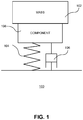
- FIG. 1 illustrates an exemplary grey-box model for a mechanical system, according to one embodiment.
- Mechanical system 100 can include a mass 102, a spring 104, and a damper 106. The dynamics of spring 104 and damper 106 are well known.
- Equations (1), (4), and (5) the dynamics of component 108 are not known, and the function T ( F ) in equation (2) can only be derived from experimental data.
- equations used to describe the model are a mix of analytic and non-analytic equations. Many real-life systems can be described using such a hybrid model.
- weight-bearing cables as an example, one may know the general form and trend of degradation of the cables; however, the degradation rate of the cables needs to be inferred from experimental data. In some embodiments, inferring such information can involve obtaining the electrical properties of the cable.
- FIG. 2 illustrates the effective load-bearing area of a cable under various crack conditions. More specifically, FIG. 2 shows a number of cables (e.g., cables 202 and 204) in various degradation conditions. From left to right, the degradation gets worse and worse, and cable 206 is completely broken. As one can see from FIG.
- the microcracks or cracks in each cable can affect the cross-sectional area of the cable. Because the current-conducting cross-sectional area is equivalent to the load-bearing (or weight-bearing) cross-sectional area of the cable, those microcracks or cracks not only reduce the load-bearing cross-sectional area in the cable, but also reduce the conducting cross-sectional area of the cable. Therefore, electrical, thermal, or magnetic resistance measurements may provide information associated with damages in the equipment (e.g., cables). Compared to mechanical measurements (e.g., measuring strains or stress), electrical or thermal measurements can be simpler to implement without interrupting the service of the equipment, thus enabling long-term fault monitoring.
- mechanical measurements e.g., measuring strains or stress
- thermal or magnetic resistance can also be used for calculating the damage variable.
- electrical resistance measurement as an example for estimating the damage variable, but the scope of this disclosure is not limited to the electrical resistance measurement.
- ⁇ the half crack length
- N the number of fatigue cycles (e.g., loading cycles)
- d ⁇ dN the rate of change of the half crack length with respect to the number of fatigue cycles
- C the material constant of the crack growth equation and a crack geometry
- m an exponent that can be selected based on the material type
- ⁇ K the range of the stress intensity factor during the fatigue cycle.
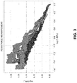
- FIG. 3 shows the resistance measurement results of a cable, according to one embodiment.
- a nearly linear trend is shown, as indicated by equation (9).
- the model parameters i.e., [ D , ⁇ , N f ]
- D is the damage variable
- a reflects the damage growth rate
- N f reflects the total useful life in terms of the number of fatigue cycles.
- FIG. 4 illustrates an exemplary particle-filtering framework for estimating the RUL of a piece of equipment, according to one embodiment.
- RUL-estimation framework 400 can include two stages, state-tracking stage 402 and prediction stage 404.
- State-tracking stage 402 is for estimating coefficients and damage variables. More specifically, state-tracking stage 402 can include system-modeling module 406 for maintaining the system model.
- noise terms e.g., Gaussian distributed noise
- State-tracking stage 402 can further include particle filter 408 for estimating the states (i.e., the model parameters). More specifically, particle filter 408 receives measurement results from measurement module 410. For example, measurement module 410 can provide measurements of electrical resistance. Based on the system model and the measurement results, particle filter 408 can output the posterior probability density function (PDF) of the states.
- PDF posterior probability density function
- a particle filter can be an effective tool for solving the state/parameter estimation problem.
- ⁇ 0,1,... t ⁇ ), particle filters can be used to find the estimation of state x(t), which consists of state variables s ( t ) and model parameters ⁇ ( t ) .
- the probability densities can be represented by continuous PDF, such as p ( x ( t )
- i 1 , ... , n p x k
- the states can be represented as a PDF, and the algorithm involves sampling the state PDF as a set of particles and associated weights. The system propagates particle values according to the model and updates weights based on measurement results.
- FIG. 5 presents a flowchart illustrating the operation process of a particle filter.
- the operation starts with initialization of particles (operation 502). More specifically, the system proposes x 0 i and propagates particles.
- the system computes a likelihood of measurement with respect to each particle (operation 504). For example, the system computes a likelihood function p z k
- the system updates particle weights based on likelihood (operation 506) and then normalizes the weights (operation 508).
- the system can then resample the particles by keeping the particles with larger weights (operation 510). This process repeats until a convergence is reached.
- system-model-tuning module 412 receives an identified model (e.g., a model with fixed model parameters) from state-tracking stage 402 and a failure threshold from failure-threshold estimation module 414.
- model parameters are fixed, the system performs run-to-failure simulations using state vectors carried by each particle.
- the predicted RUL e.g., represented by N f
- N f can be calculated by taking the weighted average of the predictions from each particle, where the weights are determined in state-tracking stage 402.
- FIG. 6 presents a flowchart illustrating the process for predicting RUL, according to one embodiment.
- the system obtains a physics-based model of the equipment under investigation (operation 602). More specifically, the physics-based model includes both the analytical description of the structure of the various components of the equipment and a semi-physical structural damage accumulation model describing the growth of the damage. More specifically, the model includes both analytical equations derived from one or more known laws of physics (e.g., Newton's Law or Ampere's Law) and semi-analytical equations obtained based on experimental data.
- laws of physics e.g., Newton's Law or Ampere's Law
- the system obtains measurement results of one or more state variables, also known as observables (operation 604).
- the measurement can be performed in service.
- the system measures at least one conductive property (e.g., electrical, thermal, or magnetic resistance) of the equipment under investigation.
- the system uses a particle filter to estimate unknown parameters of the physics-based model (operation 606). Note that a number of particles with various weights can be outputted from the particle filter.
- the estimated model parameters can include the damage growth rate.
- the system then runs a simulation to predict the RUL or TUL of the equipment (operation 608).
- the system can perform run-to-failure simulations using the state vectors (which can include damage growth rates) carried by each particle, and predict RUL by taking the weighted average of the predictions from each particle.
- the system may predict an RUL using a particle, and then compute a weighted average of the RULs for all particles.
- Bayesian inference-based filtering algorithms such as unscented Kalman filter, can also be used for state tracking and RUL prediction.
- FIG. 7A presents a diagram illustrating a simulation interface for simulating the resistance of a multi-strand cable, according to one embodiment.
- Multi-strand cable 700 can be divided into multiple sections (e.g., sections 702 and 704). Each section can be represented by a unit bundle model.
- FIG. 7B shows the modeling of a unit bundle, according to one embodiment.
- unit bundle 710 has seven strands, as shown by cross-section 720.
- the cross-sectional area is a function of damage variable D. Consequently, the strand resistance is also related to D.
- the resistivity can be associated with the material of the cable.
- the cable can be made of copper, aluminum, or stainless steel.
- Equivalent circuit 730 models the electrical behavior of two adjacent strands (e.g., strands 1 and 2) of unit bundle 710. More specifically, each strand can include strand resistance (e.g., strand 1 includes strand resistance 732 and 734, and contact resistance (e.g., contact resistance 736) exists between two adjacent strands. Depending on the number of strands and the layout of the multiple strands, a more complicated equivalent circuit model of the unit bundle can be established.
- a complete model of the multi-strand cable (e.g., multi-strand cable 700) can be accomplished by combining the unit bundle models for all segments of the cable.
- the number of strands in the load-bearing cable can be larger or smaller.
- a cable can include up to 28 strands.
- FIG. 8A shows the simulation result of the normalized resistance of a 28-strand cable as a function of time, according to one embodiment.
- the different lines shows the different simulation run and there are 20 runs.
- the initial wear/damage among the 28 strands can be considered to be randomly distributed.
- FIG. 8A shows that the trend of the simulation data follows that of the experiments (e.g., measurements).
- the non-uniform changes in resistance among the different simulation runs are due to the randomized initial damage states.
- FIG. 8B shows the simulation outcome under different initial wear conditions, according to one embodiment. More specifically, when running the simulation, the algorithm assumes normal distribution of the initial wear/damage condition among the 28 strands.
- the 10 simulation results shown in FIG. 8B are for different mean values of the initial wear. More specifically, the mean value of the initial wear has been changed from 0 to 0.1. As one can see from FIG. 8B , when the mean of the initial wear reaches a threshold (e.g., 0.1), the resistance can increase significantly.
- a threshold e.g., 0.1
- FIGs. 8C-8E show the comparison result between the particle filter predictions and the experimental measurement result, according to one embodiment. More specifically, FIG. 8C shows the predicted normalized resistance and the measurement; the more noisy data is the measurement result, and the less noisy one shows the prediction.
- FIG. 8D shows damage variable predicted by the particle filter.
- FIG. 8E shows the total useful life (TUL) predicted by the particle filter. As one can see from FIG. 8E , the prediction of the TUL may show large variations at the initial stage, but tends to converge at the second half of the measurement.
- a functional mock-up unit (FMU)-based approach can be used for model implementation.
- FMU functional mock-up unit
- a Modelica model can be established for the multi-strand cable.
- the number of strands of the cable and the length of the cable can be changed programmatically.
- the structure-based (or physics-based) model can be used for estimating spatially distributed damage (e.g., damage in cables). It can provide the advantage of taking into consideration initial wear of the equipment or structure due to manufacturing defects or handling. Particle-filter based state estimation can also estimate, by Monte Carlo simulations, process noise and the impact of the failure of an individual subcomponent (e.g., a cable strand in the multi-strand cable). If stress-strain analysis is integrated in the model, damage propagation can also be simulated. This structure- or physics-based model can be used for quick checks of experimental data.
- FIG. 9 illustrates an exemplary computer system that facilitates an RUL-prediction system, according to one embodiment.
- Computer system 900 includes a processor 902, a memory 904, and a storage device 906.
- Computer system 900 can be coupled to a display device 910, a keyboard 912, and a pointing device 914, and can also be coupled via one or more network interfaces to network 908.
- Storage device 906 can store an operating system 918, and an RUL-prediction system 920.
- RUL-prediction system 920 can include instructions, which when executed by computer system 900 can cause computer system 900 to perform methods and/or processes described in this disclosure.
- RUL-prediction system 920 can also include instructions for establishing a physics-based model (modeling module 924) and instructions for obtaining measurement results (measurement-result-obtaining module 926).
- RUL-prediction system 920 can include instructions for applying a particle filter (particle-filtering module 928) and instructions for predicting the TUL or RUL (prediction module 930).
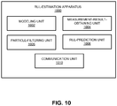
- FIG. 10 illustrates an exemplary apparatus that facilitates an RUL-estimation system, according to one embodiment.
- Apparatus 1000 can comprise a plurality of units or apparatuses that may communicate with one another via a wired, wireless, quantum light, or electrical communication channel.
- Apparatus 1000 may be realized using one or more integrated circuits, and may include fewer or more units or apparatuses than those shown in FIG. 10 .
- apparatus 1000 may be integrated in a computer system, or realized as a separate device that is capable of communicating with other computer systems and/or devices.
- apparatus 1000 can comprise units 1002-1008, which perform functions or operations similar to modules 924-930 of computer system 900 of FIG. 9 , including: a modeling unit 1002, a measurement-result-obtaining unit 1004, a particle-filtering unit 1006, and an RUL-prediction unit 1008.
- Apparatus 1000 can further include a communication unit 1010.
- the methods and processes described in the detailed description section can be embodied as code and/or data, which can be stored in a computer-readable storage medium as described above.
- a computer system reads and executes the code and/or data stored on the computer-readable storage medium, the computer system performs the methods and processes embodied as data structures and code and stored within the computer-readable storage medium.
- the methods and processes described above can be included in hardware modules or apparatus.
- the hardware modules or apparatus can include, but are not limited to, application-specific integrated circuit (ASIC) chips, field-programmable gate arrays (FPGAs), dedicated or shared processors that execute a particular software module or a piece of code at a particular time, and other programmable-logic devices now known or later developed.
- ASIC application-specific integrated circuit
- FPGA field-programmable gate arrays
- dedicated or shared processors that execute a particular software module or a piece of code at a particular time
- other programmable-logic devices now known or later developed.
Landscapes
- Engineering & Computer Science (AREA)
- Physics & Mathematics (AREA)
- Theoretical Computer Science (AREA)
- General Physics & Mathematics (AREA)
- Evolutionary Computation (AREA)
- General Engineering & Computer Science (AREA)
- Computer Hardware Design (AREA)
- Geometry (AREA)
- Aviation & Aerospace Engineering (AREA)
- Computational Mathematics (AREA)
- Pure & Applied Mathematics (AREA)
- Artificial Intelligence (AREA)
- Probability & Statistics with Applications (AREA)
- Data Mining & Analysis (AREA)
- Mathematical Analysis (AREA)
- Mathematical Optimization (AREA)
- Algebra (AREA)
- Computing Systems (AREA)
- Mathematical Physics (AREA)
- Software Systems (AREA)
- Testing Of Devices, Machine Parts, Or Other Structures Thereof (AREA)
- Testing Resistance To Weather, Investigating Materials By Mechanical Methods (AREA)
- Investigating Or Analyzing Materials By The Use Of Magnetic Means (AREA)
- Investigating Or Analyzing Materials By The Use Of Electric Means (AREA)
Abstract
Description
- This disclosure is generally related to a system and method for fault diagnosis and prognosis. More specifically, this disclosure is related to implementing physics-based modeling for predicting a remaining useful life (RUL) of engineering structures or equipment, such as load-bearing cables.
- Detection and diagnosis of mechanical faults in mechanical and electrical equipment can be very important in many industries. Correct prediction of a total useful life (TUL) or remaining useful life (RUL) of such equipment can have great financial impact. For example, cables carrying data or electrical charges are essential in many industries, including the telecommunication industry, automotive industry, healthcare industry, power generation and distribution industry, etc. Failures of a load-bearing cable may sometimes lead to catastrophic outcomes.
- There are two types of approach for fault diagnosis, including model-based diagnostic techniques and data-driven diagnostic techniques. In model-based approaches, a model of the machinery being diagnosed (i.e., the system) can be provided to the diagnosis engine. Moreover, the diagnosis engine can receive values of the parameters of the model and some of the input and output values. The goal of the model-based diagnosis is to determine, from only the system model and available input/output values, whether a fault is present, and if so, the cause of the fault. This process can require a great amount of computation resources. On the other hand, data-driven approaches use statistical models (e.g., classifiers or regressors) trained with labeled data that describe the behavior of the system under different fault modes. This data-driven approach requires a large amount of data in order to build meaningful statistical models. However, such a condition may not be easily satisfied.
- Many different types of electrical or mechanical equipment use materials with various conductive (e.g., thermally, electrically, or magnetically) properties. Examples of such materials can include metals, alloys, and carbon composites. Some applications (e.g., signal and charge cables) directly use the conductive property to fulfill designed functions. Other applications (e.g., carbon composites used on aircraft as structural materials) may only use a particular material due to its superior mechanical properties. Materials in these engineering applications are subject to cyclic loading, such as vibrations (e.g., for harness cable used in the vehicles) and electric charging cycles (e.g., for electrical cables), which affect fatigue damage evaluation.
- One embodiment can provide a system for estimating a useful life of a load-bearing structure at least partly made of a conductive material. During operation, the system establishes a physics-based damage model for the load-bearing structure, performs a dynamic measurement to obtain at least one conductive property of the load-bearing structure as a function of fatigue cycles, estimates parameters of the physics-based damage model based on the measured conductive property, and estimates the useful life of the load-bearing structure based on the estimated parameters of the physics-based damage model.
- In a variation on this embodiment, the physics-based damage model comprises an analytical portion modeling a physical structure of the load-bearing structure and a semi-analytical portion modeling damage degradation.
- In a variation on this embodiment, the at least conductive property comprises one or more of: an electrical resistance, a thermal resistance, and a magnetic resistance.
- In a variation on this embodiment, estimating the parameters of the physics-based damage model comprises applying a Bayesian inference-based filtering algorithm.
- In a further variation, the Bayesian inference-based filtering algorithm comprises a particle-filtering algorithm.
- In a variation on this embodiment, the estimated parameters of the physics-based damage model comprise a damage variable, a parameter indicating the damage growth rate, and a parameter indicating the total useful life.
- In a variation on this embodiment, the load-bearing structure comprises a load-bearing cable.
- One embodiment can provide a system for monitoring structural damage in a load-bearing structure at least partly made of a conductive material. During operation, the system establishes a physics-based damage model for the load-bearing structure, performs a dynamic measurement to obtain at least one conductive property of the load-bearing structure as a function of fatigue cycles, and infers a state of damage and a damage growth rate by estimating parameters of the physics-based damage model based on the measured conductive property.
-
FIG. 1 illustrates an exemplary grey-box model for a mechanical system, according to one embodiment. -
FIG. 2 illustrates the effective load-bearing area of a cable under various crack conditions. -
FIG. 3 shows the resistance measurement result of a cable, according to one embodiment. -
FIG. 4 illustrates an exemplary particle-filtering framework for estimating the remaining useful life (RUL) of a piece of equipment, according to one embodiment. -
FIG. 5 presents a flowchart illustrating the operation process of a particle filter. -
FIG. 6 presents a flowchart illustrating the process for predicting RUL, according to one embodiment. -
FIG. 7A presents a diagram illustrating a simulation interface for simulating the resistance of a multi-strand cable, according to one embodiment. -
FIG. 7B shows the modeling of a unit bundle, according to one embodiment. -
FIG. 8A shows the simulation results of the damage variable of a 28-strand cable as a function of time, according to one embodiment. -
FIG. 8B shows the damage simulation under different initial wear conditions, according to one embodiment. -
FIGs. 8C-8E show the comparison result between the particle filter predictions and the experimental measurement result, according to one embodiment. -
FIG. 9 illustrates an exemplary computer system that facilitates an RUL-prediction system, according to one embodiment. -
FIG. 10 illustrates an exemplary apparatus that facilitates an RUL-estimation system, according to one embodiment. - The embodiments described herein solve the technical problem of performing fault diagnosis and prognosis on mechanical and/or electrical equipment (e.g., load-bearing cables) that involve electrically, thermally, or magnetically conductive materials. More specifically, the system can map the mechanical life of a piece of equipment (e.g., a cable) to its conductive properties (e.g., electrical, thermal, or magnetic resistance). For example, by measuring the electrical resistance of a cable, the system can predict the TUL or RUL of the cable. In some embodiments, a physics-based model can be used to link the mechanical and conductive properties of the equipment, and a semi-analytical damage accumulation module can be established based on both analytical modeling and experimental investigations. Moreover, the system integrates the physics-based model with a particle-filtering framework to estimate the model parameters, thus being capable of predicting TUL or RUL.
- Physics-based modeling can be used to capture the essential physics of a real-life problem. Such modeling can be used to predict the behavior of a system under conditions that have not yet been studied or for which data is not available yet. There are three types of physics-based models, the white-box model, the black-box model, and the grey-box model.
- In a white-box model, the system can be decomposed into sub-components based on its physical structure. For example, a multi-strand cable can be decomposed into multiple strands. The physical behavior of each component (e.g., a single strand of cable) can be represented by a set of analytical equations (e.g., differential equations). For example, the electrical conduction of a single strand of cable can be expressed using analytical equations. The overall behavior can result from interactions among the sub-components. The parameters of the white-box model have physical meanings and are either chosen at design time (e.g., technical specifications) or estimated from data (e.g., when the system is in use).
- When little knowledge of the internal mechanisms of the system is available, it's impossible to implement white-box models. Instead, a black-box model, which represents a mapping between the inputs and outputs of the system, can be used. In the black-box model, the parameters have no physical meanings. Various machine-learning techniques, such as deep-learning neural networks can be used to infer parameters of the black-box model. For example, the degradation rate of a cable can be inferred using neural networks based on loading and damage conditions.
- In many situations, not all details about the inner workings of the system are known. In such a situation, a model for the "missing" part can be built from experimental data. Such a model can be referred to as a grey-box model. Grey-box modeling is also known as semi-physical modeling, where the system can be described using a set of analytical equations representing known physical behaviors of sub-components in the system and one or more additional non-analytical equations representing unknown physical behaviors.
-
FIG. 1 illustrates an exemplary grey-box model for a mechanical system, according to one embodiment.Mechanical system 100 can include amass 102, aspring 104, and adamper 106. The dynamics ofspring 104 anddamper 106 are well known. In addition,mechanical system 100 can also include acomponent 108, the dynamics of which are not known but can be inferred from experimental data. Using grey-box modeling, one can describemechanical system 100 using the following set of equations.


- In the above equations, m is the mass, x is the displacement, g is the gravitational constant, Fs are forces, and k and c are spring and damper constants, respectively. The dynamics of the mass, spring, and damper can be expressed using well-defined equations (i.e., equations (1), (4), and (5)). However, the dynamics of
component 108 are not known, and the function T(F) in equation (2) can only be derived from experimental data. As one can see, equations used to describe the model are a mix of analytic and non-analytic equations. Many real-life systems can be described using such a hybrid model. Using weight-bearing cables as an example, one may know the general form and trend of degradation of the cables; however, the degradation rate of the cables needs to be inferred from experimental data. In some embodiments, inferring such information can involve obtaining the electrical properties of the cable. - Various conductive properties (e.g., electrically conductive, thermally conductive, or magnetically conductive property) can be tightly linked to material structure at both micro and macro scale. Damages in the material can result in change of load-bearing capability as well as the electrical, thermal, and magnetic conduction paths.
FIG. 2 illustrates the effective load-bearing area of a cable under various crack conditions. More specifically,FIG. 2 shows a number of cables (e.g.,cables 202 and 204) in various degradation conditions. From left to right, the degradation gets worse and worse, andcable 206 is completely broken. As one can see fromFIG. 2 , the microcracks or cracks in each cable (e.g.,microcrack 208 incable 204 or crack 210 in cable 206) can affect the cross-sectional area of the cable. Because the current-conducting cross-sectional area is equivalent to the load-bearing (or weight-bearing) cross-sectional area of the cable, those microcracks or cracks not only reduce the load-bearing cross-sectional area in the cable, but also reduce the conducting cross-sectional area of the cable. Therefore, electrical, thermal, or magnetic resistance measurements may provide information associated with damages in the equipment (e.g., cables). Compared to mechanical measurements (e.g., measuring strains or stress), electrical or thermal measurements can be simpler to implement without interrupting the service of the equipment, thus enabling long-term fault monitoring. - Material or structural damages can often grow with time, leading to a progressive internal deterioration of the material. One may define a normalized damage variable D, where D = 0 refers to the non-damaged state and D = 1 refers to the completely failed (e.g., broken) state. Based on the analogy between electrical conduction paths and mechanical load-bearing, the damage variable can also be expressed as a function of the cross-sectional area:


- Fatigue-induced structural damages often accumulate over time. As discussed previously, fatigue-damage-cumulative models of equipment typically require both analytical and non-analytical (or semi-analytical) formulae based on continuum damage mechanics theory or experimental investigations. Paris' law has been widely used to describe crack growth in homogeneous material. More specifically, Paris' law uses micro-scale structural properties, such as the crack size and localized stress intensity. Paris' law can be expressed as:


- Inspired by Paris' law, one can derive a power-law formula for a micro-scale damage variable (i.e., D) as:



-
FIG. 3 shows the resistance measurement results of a cable, according to one embodiment. As one can see from the drawing, a nearly linear trend is shown, as indicated by equation (9). The end of the curve (i.e., r = 1) represents the situation of a completely broken cable. Given the inputs (i.e., the number of fatigue cycles N) and outputs (e.g., measurements of r) of the model, one can estimate the model parameters (i.e., [D, α, N f]), where D is the damage variable, a reflects the damage growth rate, and Nf reflects the total useful life in terms of the number of fatigue cycles. - Various Bayesian inference-based algorithms can be used to estimate the parameters of the aforementioned fatigue accumulation model. Due to the non-linear relationships among the model parameters, particle filters have been used for estimating the model parameters.
FIG. 4 illustrates an exemplary particle-filtering framework for estimating the RUL of a piece of equipment, according to one embodiment. - In
FIG. 4 , RUL-estimation framework 400 can include two stages, state-trackingstage 402 andprediction stage 404. State-tracking stage 402 is for estimating coefficients and damage variables. More specifically, state-trackingstage 402 can include system-modeling module 406 for maintaining the system model. The state vector of the model can be formulated by choosing a set of variables: x = [D, α, NL ] T. The state space model can be described by a state-transition equation x k+1 = f(x k ) + v 1,k , and a measurement equation rk = g(x k ) + v 2,k , where v 1,k and v 2,k are noise terms (e.g., Gaussian distributed noise), g(x k ) represents the electrical network of the material system, f(x k ) represents the physics-based damage accumulation model, and r is the normalized resistance. - State-
tracking stage 402 can further includeparticle filter 408 for estimating the states (i.e., the model parameters). More specifically,particle filter 408 receives measurement results frommeasurement module 410. For example,measurement module 410 can provide measurements of electrical resistance. Based on the system model and the measurement results,particle filter 408 can output the posterior probability density function (PDF) of the states. - A particle filter can be an effective tool for solving the state/parameter estimation problem. Given a set of noisy measurements (e.g., Z1:t = {z(τ)|τ = 0,1,...t}), particle filters can be used to find the estimation of state x(t), which consists of state variables s(t) and model parameters θ(t). The probability densities can be represented by continuous PDF, such as p(x(t)|Z 1:t ).
- A particle filter can iteratively approximate the posterior PDF as a set:


-
FIG. 5 presents a flowchart illustrating the operation process of a particle filter. The operation starts with initialization of particles (operation 502). More specifically, the system proposes


- Returning to
FIG. 4 , inprediction stage 404 of RUL-estimation framework 400, system-model-tuningmodule 412 receives an identified model (e.g., a model with fixed model parameters) from state-trackingstage 402 and a failure threshold from failure-threshold estimation module 414. Inprediction stage 404, the model parameters are fixed, the system performs run-to-failure simulations using state vectors carried by each particle. The predicted RUL (e.g., represented by N f) can be calculated by taking the weighted average of the predictions from each particle, where the weights are determined in state-trackingstage 402. -
FIG. 6 presents a flowchart illustrating the process for predicting RUL, according to one embodiment. During operation, the system obtains a physics-based model of the equipment under investigation (operation 602). More specifically, the physics-based model includes both the analytical description of the structure of the various components of the equipment and a semi-physical structural damage accumulation model describing the growth of the damage. More specifically, the model includes both analytical equations derived from one or more known laws of physics (e.g., Newton's Law or Ampere's Law) and semi-analytical equations obtained based on experimental data. - The system obtains measurement results of one or more state variables, also known as observables (operation 604). The measurement can be performed in service. In some embodiments, the system measures at least one conductive property (e.g., electrical, thermal, or magnetic resistance) of the equipment under investigation. The system then uses a particle filter to estimate unknown parameters of the physics-based model (operation 606). Note that a number of particles with various weights can be outputted from the particle filter. The estimated model parameters can include the damage growth rate. The system then runs a simulation to predict the RUL or TUL of the equipment (operation 608). In some embodiments, the system can perform run-to-failure simulations using the state vectors (which can include damage growth rates) carried by each particle, and predict RUL by taking the weighted average of the predictions from each particle. In other words, the system may predict an RUL using a particle, and then compute a weighted average of the RULs for all particles.
- In addition to the aforementioned particle-filtering algorithm, other Bayesian inference-based filtering algorithms, such as unscented Kalman filter, can also be used for state tracking and RUL prediction.
-
FIG. 7A presents a diagram illustrating a simulation interface for simulating the resistance of a multi-strand cable, according to one embodiment.Multi-strand cable 700 can be divided into multiple sections (e.g.,sections 702 and 704). Each section can be represented by a unit bundle model. -
FIG. 7B shows the modeling of a unit bundle, according to one embodiment. In the example shown inFIG. 7B , unit bundle 710 has seven strands, as shown bycross-section 720. Each strand can be represented by a resistor with resistance value calculated from
Equivalent circuit 730 models the electrical behavior of two adjacent strands (e.g.,strands 1 and 2) of unit bundle 710. More specifically, each strand can include strand resistance (e.g.,strand 1 includesstrand resistance - A complete model of the multi-strand cable (e.g., multi-strand cable 700) can be accomplished by combining the unit bundle models for all segments of the cable. In the example shown in
FIG. 7B , there are 7 strands of cable. In practice, the number of strands in the load-bearing cable can be larger or smaller. In the following example, a cable can include up to 28 strands.FIG. 8A shows the simulation result of the normalized resistance of a 28-strand cable as a function of time, according to one embodiment. InFIG. 8A , the different lines shows the different simulation run and there are 20 runs. The initial wear/damage among the 28 strands can be considered to be randomly distributed.FIG. 8A shows that the trend of the simulation data follows that of the experiments (e.g., measurements). The non-uniform changes in resistance among the different simulation runs are due to the randomized initial damage states. -
FIG. 8B shows the simulation outcome under different initial wear conditions, according to one embodiment. More specifically, when running the simulation, the algorithm assumes normal distribution of the initial wear/damage condition among the 28 strands. The 10 simulation results shown inFIG. 8B are for different mean values of the initial wear. More specifically, the mean value of the initial wear has been changed from 0 to 0.1. As one can see fromFIG. 8B , when the mean of the initial wear reaches a threshold (e.g., 0.1), the resistance can increase significantly. -
FIGs. 8C-8E show the comparison result between the particle filter predictions and the experimental measurement result, according to one embodiment. More specifically,FIG. 8C shows the predicted normalized resistance and the measurement; the more noisy data is the measurement result, and the less noisy one shows the prediction.FIG. 8D shows damage variable predicted by the particle filter.FIG. 8E shows the total useful life (TUL) predicted by the particle filter. As one can see fromFIG. 8E , the prediction of the TUL may show large variations at the initial stage, but tends to converge at the second half of the measurement. - In some embodiments, a functional mock-up unit (FMU)-based approach can be used for model implementation. For example, a Modelica model can be established for the multi-strand cable. Using the Modelica model, the number of strands of the cable and the length of the cable can be changed programmatically.
- The structure-based (or physics-based) model (e.g., models shown in
FIGs. 7A-7B ) can be used for estimating spatially distributed damage (e.g., damage in cables). It can provide the advantage of taking into consideration initial wear of the equipment or structure due to manufacturing defects or handling. Particle-filter based state estimation can also estimate, by Monte Carlo simulations, process noise and the impact of the failure of an individual subcomponent (e.g., a cable strand in the multi-strand cable). If stress-strain analysis is integrated in the model, damage propagation can also be simulated. This structure- or physics-based model can be used for quick checks of experimental data. -
FIG. 9 illustrates an exemplary computer system that facilitates an RUL-prediction system, according to one embodiment.Computer system 900 includes aprocessor 902, amemory 904, and astorage device 906.Computer system 900 can be coupled to adisplay device 910, akeyboard 912, and apointing device 914, and can also be coupled via one or more network interfaces tonetwork 908.Storage device 906 can store anoperating system 918, and an RUL-prediction system 920. - RUL-
prediction system 920 can include instructions, which when executed bycomputer system 900 can causecomputer system 900 to perform methods and/or processes described in this disclosure. RUL-prediction system 920 can also include instructions for establishing a physics-based model (modeling module 924) and instructions for obtaining measurement results (measurement-result-obtaining module 926). Furthermore, RUL-prediction system 920 can include instructions for applying a particle filter (particle-filtering module 928) and instructions for predicting the TUL or RUL (prediction module 930). -
FIG. 10 illustrates an exemplary apparatus that facilitates an RUL-estimation system, according to one embodiment.Apparatus 1000 can comprise a plurality of units or apparatuses that may communicate with one another via a wired, wireless, quantum light, or electrical communication channel.Apparatus 1000 may be realized using one or more integrated circuits, and may include fewer or more units or apparatuses than those shown inFIG. 10 . Further,apparatus 1000 may be integrated in a computer system, or realized as a separate device that is capable of communicating with other computer systems and/or devices. Specifically,apparatus 1000 can comprise units 1002-1008, which perform functions or operations similar to modules 924-930 ofcomputer system 900 ofFIG. 9 , including: amodeling unit 1002, a measurement-result-obtainingunit 1004, a particle-filtering unit 1006, and an RUL-prediction unit 1008.Apparatus 1000 can further include acommunication unit 1010. - The methods and processes described in the detailed description section can be embodied as code and/or data, which can be stored in a computer-readable storage medium as described above. When a computer system reads and executes the code and/or data stored on the computer-readable storage medium, the computer system performs the methods and processes embodied as data structures and code and stored within the computer-readable storage medium.
- Furthermore, the methods and processes described above can be included in hardware modules or apparatus. The hardware modules or apparatus can include, but are not limited to, application-specific integrated circuit (ASIC) chips, field-programmable gate arrays (FPGAs), dedicated or shared processors that execute a particular software module or a piece of code at a particular time, and other programmable-logic devices now known or later developed. When the hardware modules or apparatus are activated, they perform the methods and processes included within them.
Claims (20)
- A method for estimating useful life of a load-bearing structure at least partly made of a conductive material, comprising:establishing a physics-based damage model for the load-bearing structure;performing a dynamic measurement to obtain at least one conductive property of the load-bearing structure as a function of fatigue cycles;estimating parameters of the physics-based damage model based on the measured conductive property; andestimating the useful life of the load-bearing structure based on the estimated parameters of the physics-based damage model.
- The method of claim 1, wherein the physics-based damage model comprises an analytical portion modeling a physical structure of the load-bearing structure and a semi-analytical portion modeling damage degradation.
- The method of claim 1, wherein the at least one conductive property comprises one or more of: an electrical resistance, a thermal resistance, and a magnetic resistance.
- The method of claim 1, wherein estimating the parameters of the physics-based damage model comprises applying a Bayesian inference-based filtering algorithm.
- The method of claim 4, wherein the Bayesian inference-based filtering algorithm comprises a particle-filtering algorithm.
- The method of claim 1, wherein the estimated parameters of the physics-based damage model comprise a damage variable, a parameter indicating a damage growth rate, and a parameter indicating total useful life.
- The method of claim 1, wherein the load-bearing structure comprises a load-bearing cable.
- A computer system, comprising:a processor; anda storage device coupled to the processor and storing instructions, which when executed by the processor cause the processor to perform a method for estimating useful life of a load-bearing structure at least partly made of a conductive material, the method comprising:establishing a physics-based damage model for the load-bearing structure;performing a dynamic measurement to obtain at least one conductive property of the load-bearing structure as a function of fatigue cycles;estimating parameters of the physics-based damage model based on the measured conductive property; andestimating the useful life of the load-bearing structure based on the estimated parameters of the physics-based damage model.
- The computer system of claim 8, wherein the physics-based damage model comprises an analytical portion modeling a physical structure of the load-bearing structure and a semi-analytical portion modeling damage degradation.
- The computer system of claim 8, wherein the at least one conductive property comprises one or more of an electrical resistance, a thermal resistance, and a magnetic resistance.
- The computer system of claim 8, wherein estimating the parameters of the physics-based damage model comprises applying a Bayesian inference-based filtering algorithm.
- The computer system of claim 11, wherein the Bayesian inference-based filtering algorithm comprises a particle-filtering algorithm.
- The computer system of claim 8, wherein the estimated parameters of the physics-based damage model comprise a damage variable, a parameter indicating a damage growth rate, and a parameter indicating total useful life.
- The computer system of claim 8, wherein the load-bearing structure comprises a load-bearing cable.
- A method for monitoring structural damage in a load-bearing structure at least partly made of a conductive material, comprising:establishing a physics-based damage model for the load-bearing structure;performing a dynamic measurement to obtain at least one conductive property of the load-bearing structure as a function of fatigue cycles; andinferring a state of damage and a damage growth rate by estimating parameters of the physics-based damage model based on the measured conductive property.
- The method of claim 15, wherein the physics-based damage model comprises an analytical portion modeling a physical structure of the load-bearing structure and a semi-analytical portion modeling damage degradation.
- The method of claim 15, wherein the at least one conductive property comprises one or more of: an electrical resistance, a thermal resistance, and a magnetic resistance.
- The method of claim 15, wherein estimating the parameters of the physics-based damage model comprises applying a Bayesian inference-based algorithm.
- The method of claim 18, wherein the Bayesian inference-based filtering algorithm comprises a particle-filtering algorithm.
- The method of claim 15, wherein the load-bearing structure comprises a load-bearing cable.
Applications Claiming Priority (1)
| Application Number | Priority Date | Filing Date | Title |
|---|---|---|---|
| US16/148,707 US11126764B2 (en) | 2018-10-01 | 2018-10-01 | Physics-based model particle-filtering framework for predicting RUL using resistance measurements |
Publications (2)
| Publication Number | Publication Date |
|---|---|
| EP3633343A1 true EP3633343A1 (en) | 2020-04-08 |
| EP3633343B1 EP3633343B1 (en) | 2024-11-06 |
Family
ID=68084712
Family Applications (1)
| Application Number | Title | Priority Date | Filing Date |
|---|---|---|---|
| EP19200305.1A Active EP3633343B1 (en) | 2018-10-01 | 2019-09-27 | A physics-based model particle-filtering framework for predicting rul using resistance measurements |
Country Status (3)
| Country | Link |
|---|---|
| US (1) | US11126764B2 (en) |
| EP (1) | EP3633343B1 (en) |
| JP (1) | JP2020056783A (en) |
Cited By (1)
| Publication number | Priority date | Publication date | Assignee | Title |
|---|---|---|---|---|
| CN112100731A (en) * | 2020-11-16 | 2020-12-18 | 湖南大学 | Method and system for establishing fatigue load calculation model |
Families Citing this family (8)
| Publication number | Priority date | Publication date | Assignee | Title |
|---|---|---|---|---|
| EP3710667B1 (en) | 2017-11-15 | 2023-04-26 | Services Pétroliers Schlumberger | Field operations system with filter |
| CN111086017B (en) * | 2018-10-24 | 2024-09-13 | 发那科株式会社 | Robot system |
| CN111504582B (en) * | 2020-04-07 | 2022-07-26 | 上海卫星工程研究所 | Novel flexible cable rigidity measuring method and system |
| CN113255209B (en) * | 2021-04-27 | 2022-06-07 | 燕山大学 | A Prediction Method for Remaining Life of Gearbox Bearings |
| US20230400846A1 (en) * | 2022-06-14 | 2023-12-14 | Novity, Inc. | Hybrid reasoning based on physics and machine learning for prognostics of systems with conflated degradation modes |
| JP2024094921A (en) * | 2022-12-28 | 2024-07-10 | 住友電気工業株式会社 | Cable system, remaining life prediction device, remaining life prediction method, and computer program |
| US12578719B2 (en) * | 2023-02-03 | 2026-03-17 | Xerox Corporation | Prediction of remaining useful life of an asset using conformal mathematical filtering |
| CN115983081B (en) * | 2023-03-17 | 2023-07-14 | 湖南云箭科技有限公司 | Method and system for processing parameters of external stores for prototype airborne equipment replacement |
Citations (3)
| Publication number | Priority date | Publication date | Assignee | Title |
|---|---|---|---|---|
| US20120223727A1 (en) * | 2008-05-08 | 2012-09-06 | GM Global Technology Operations LLC | Method of controlling active material actuation utilizing an operational envelope |
| WO2014107303A1 (en) * | 2013-01-04 | 2014-07-10 | Siemens Corporation | Probabilistic modeling and sizing of embedded flaws in nondestructive inspections for fatigue damage prognostics and structural integrity assessment |
| EP3255588A1 (en) * | 2016-06-07 | 2017-12-13 | Honeywell International Inc. | Probabilistic remaining usage life of aircraft structures |
Family Cites Families (14)
| Publication number | Priority date | Publication date | Assignee | Title |
|---|---|---|---|---|
| GB9716216D0 (en) * | 1997-07-31 | 1997-10-08 | Era Patents Ltd | Measuring device |
| JP2003083871A (en) * | 2001-09-12 | 2003-03-19 | Mitsubishi Electric Corp | Reliability test method for joints of electronic components |
| JP4931797B2 (en) * | 2004-03-16 | 2012-05-16 | オーチス エレベータ カンパニー | Tensile support strength monitoring system and method |
| US7801690B2 (en) * | 2004-03-16 | 2010-09-21 | Otis Elevator Company | Tensile support strength measurement system and method |
| EP2223089A1 (en) * | 2007-12-14 | 2010-09-01 | Ab Skf | Method of determining fatigue life and remaining life |
| JP6081055B2 (en) * | 2011-11-16 | 2017-02-15 | 株式会社東芝 | Electronic component and measuring method |
| US20140039806A1 (en) * | 2012-08-02 | 2014-02-06 | Siemens Corporation | Estimating remaining useful life from prognostic features discovered using genetic programming |
| US9280620B2 (en) * | 2012-10-16 | 2016-03-08 | Siemens Aktiengesellschaft | Method and system for probabilistic fatigue crack life estimation |
| JP6163882B2 (en) * | 2013-05-30 | 2017-07-19 | 株式会社安川電機 | Prediction system |
| US9486619B2 (en) * | 2014-02-11 | 2016-11-08 | Case Western Reserve University | Interconnect devices, systems, and methods for bridging electronic devices |
| US9932203B2 (en) * | 2015-07-31 | 2018-04-03 | Inventio Ag | Method and device for detecting a deterioration state of a load bearing capacity in a suspension member arrangement for an elevator |
| CN105699843A (en) * | 2016-02-04 | 2016-06-22 | 华中科技大学 | Electric cable running state diagnosis method and system |
| US9989579B2 (en) * | 2016-06-20 | 2018-06-05 | Eaton Intelligent Power Limited | Monitoring systems and methods for detecting thermal-mechanical strain fatigue in an electrical fuse |
| EP3596439A4 (en) * | 2017-03-13 | 2021-03-31 | General Electric Company | PREDICTION OF THE SPREAD OF A FATIGUE CRACK |
-
2018
- 2018-10-01 US US16/148,707 patent/US11126764B2/en active Active
-
2019
- 2019-09-13 JP JP2019167097A patent/JP2020056783A/en active Pending
- 2019-09-27 EP EP19200305.1A patent/EP3633343B1/en active Active
Patent Citations (3)
| Publication number | Priority date | Publication date | Assignee | Title |
|---|---|---|---|---|
| US20120223727A1 (en) * | 2008-05-08 | 2012-09-06 | GM Global Technology Operations LLC | Method of controlling active material actuation utilizing an operational envelope |
| WO2014107303A1 (en) * | 2013-01-04 | 2014-07-10 | Siemens Corporation | Probabilistic modeling and sizing of embedded flaws in nondestructive inspections for fatigue damage prognostics and structural integrity assessment |
| EP3255588A1 (en) * | 2016-06-07 | 2017-12-13 | Honeywell International Inc. | Probabilistic remaining usage life of aircraft structures |
Cited By (2)
| Publication number | Priority date | Publication date | Assignee | Title |
|---|---|---|---|---|
| CN112100731A (en) * | 2020-11-16 | 2020-12-18 | 湖南大学 | Method and system for establishing fatigue load calculation model |
| CN112100731B (en) * | 2020-11-16 | 2021-03-02 | 湖南大学 | A method and system for establishing a fatigue load calculation model |
Also Published As
| Publication number | Publication date |
|---|---|
| EP3633343B1 (en) | 2024-11-06 |
| JP2020056783A (en) | 2020-04-09 |
| US11126764B2 (en) | 2021-09-21 |
| US20200104437A1 (en) | 2020-04-02 |
Similar Documents
| Publication | Publication Date | Title |
|---|---|---|
| EP3633343B1 (en) | A physics-based model particle-filtering framework for predicting rul using resistance measurements | |
| Zang et al. | Hybrid remaining useful life prediction method. A case study on railway D-cables | |
| EP2909760B1 (en) | Method and system for probabilistic fatigue crack life estimation | |
| Herzog et al. | Machine and component residual life estimation through the application of neural networks | |
| CN113962253B (en) | Bearing residual life prediction method and system based on depth wavelet extreme learning machine | |
| CN107329088A (en) | The health status diagnostic device and method of battery | |
| JP6711323B2 (en) | Abnormal state diagnosis method and abnormal state diagnosis device | |
| CN113295399B (en) | Method, device, electronic equipment and storage medium for evaluating converter valve component state | |
| Wang et al. | Probabilistic analysis for remaining useful life prediction and reliability assessment | |
| CN111079270B (en) | A bearing remaining life prediction method based on binary mixed stochastic process | |
| EP3637121B1 (en) | System and method of adaptive remaining useful life estimation using constraint convex regression from degradation measurement | |
| Laayouj et al. | Lithium-ion battery degradation assessment and remaining useful life estimation in hybrid electric vehicle | |
| Mohanty et al. | Gaussian process time series model for life prognosis of metallic structures | |
| Yazdanipour et al. | Stochastic fatigue crack growth analysis of metallic structures under multiple thermal–mechanical stress levels | |
| Sankararaman et al. | An uncertainty quantification framework for prognostics and condition-based monitoring | |
| EP3916402B1 (en) | A method for monitoring the electric insulation status of a piece of equipment for mv or hv electric systems | |
| Sankararaman et al. | Uncertainty in prognostics and health management: An overview | |
| Sankararaman et al. | Uncertainty in prognostics: Computational methods and practical challenges | |
| Safavi et al. | Battery life prediction using physics-based modeling and coati optimization | |
| Li et al. | Remaining life prediction of cores based on data-driven and physical modeling methods | |
| KR102510547B1 (en) | Neural network based prognostic and health management using neural network, and thereof | |
| Fouka et al. | State of Charge Prediction of EV Li-ion Batteries with Machine Learning: A Comparative Analysis | |
| Laayouj et al. | Prognosis of degradation based on a new dynamic method for remaining useful life prediction | |
| Sankararaman | Uncertainty representation, quantification, and management in prognostics | |
| Nguyen et al. | Dynamic-weighted ensemble for fatigue crack degradation state prediction |
Legal Events
| Date | Code | Title | Description |
|---|---|---|---|
| PUAI | Public reference made under article 153(3) epc to a published international application that has entered the european phase |
Free format text: ORIGINAL CODE: 0009012 |
|
| STAA | Information on the status of an ep patent application or granted ep patent |
Free format text: STATUS: THE APPLICATION HAS BEEN PUBLISHED |
|
| AK | Designated contracting states |
Kind code of ref document: A1 Designated state(s): AL AT BE BG CH CY CZ DE DK EE ES FI FR GB GR HR HU IE IS IT LI LT LU LV MC MK MT NL NO PL PT RO RS SE SI SK SM TR |
|
| AX | Request for extension of the european patent |
Extension state: BA ME |
|
| STAA | Information on the status of an ep patent application or granted ep patent |
Free format text: STATUS: REQUEST FOR EXAMINATION WAS MADE |
|
| 17P | Request for examination filed |
Effective date: 20201008 |
|
| RBV | Designated contracting states (corrected) |
Designated state(s): AL AT BE BG CH CY CZ DE DK EE ES FI FR GB GR HR HU IE IS IT LI LT LU LV MC MK MT NL NO PL PT RO RS SE SI SK SM TR |
|
| STAA | Information on the status of an ep patent application or granted ep patent |
Free format text: STATUS: EXAMINATION IS IN PROGRESS |
|
| 17Q | First examination report despatched |
Effective date: 20220628 |
|
| GRAP | Despatch of communication of intention to grant a patent |
Free format text: ORIGINAL CODE: EPIDOSNIGR1 |
|
| STAA | Information on the status of an ep patent application or granted ep patent |
Free format text: STATUS: GRANT OF PATENT IS INTENDED |
|
| INTG | Intention to grant announced |
Effective date: 20240513 |
|
| GRAS | Grant fee paid |
Free format text: ORIGINAL CODE: EPIDOSNIGR3 |
|
| GRAA | (expected) grant |
Free format text: ORIGINAL CODE: 0009210 |
|
| STAA | Information on the status of an ep patent application or granted ep patent |
Free format text: STATUS: THE PATENT HAS BEEN GRANTED |
|
| AK | Designated contracting states |
Kind code of ref document: B1 Designated state(s): AL AT BE BG CH CY CZ DE DK EE ES FI FR GB GR HR HU IE IS IT LI LT LU LV MC MK MT NL NO PL PT RO RS SE SI SK SM TR |
|
| REG | Reference to a national code |
Ref country code: GB Ref legal event code: FG4D |
|
| REG | Reference to a national code |
Ref country code: CH Ref legal event code: EP |
|
| REG | Reference to a national code |
Ref country code: DE Ref legal event code: R096 Ref document number: 602019061430 Country of ref document: DE |
|
| REG | Reference to a national code |
Ref country code: IE Ref legal event code: FG4D |
|
| REG | Reference to a national code |
Ref country code: LT Ref legal event code: MG9D |
|
| REG | Reference to a national code |
Ref country code: NL Ref legal event code: MP Effective date: 20241106 |
|
| PG25 | Lapsed in a contracting state [announced via postgrant information from national office to epo] |
Ref country code: PT Free format text: LAPSE BECAUSE OF FAILURE TO SUBMIT A TRANSLATION OF THE DESCRIPTION OR TO PAY THE FEE WITHIN THE PRESCRIBED TIME-LIMIT Effective date: 20250306 Ref country code: IS Free format text: LAPSE BECAUSE OF FAILURE TO SUBMIT A TRANSLATION OF THE DESCRIPTION OR TO PAY THE FEE WITHIN THE PRESCRIBED TIME-LIMIT Effective date: 20250306 Ref country code: HR Free format text: LAPSE BECAUSE OF FAILURE TO SUBMIT A TRANSLATION OF THE DESCRIPTION OR TO PAY THE FEE WITHIN THE PRESCRIBED TIME-LIMIT Effective date: 20241106 |
|
| PG25 | Lapsed in a contracting state [announced via postgrant information from national office to epo] |
Ref country code: FI Free format text: LAPSE BECAUSE OF FAILURE TO SUBMIT A TRANSLATION OF THE DESCRIPTION OR TO PAY THE FEE WITHIN THE PRESCRIBED TIME-LIMIT Effective date: 20241106 Ref country code: NL Free format text: LAPSE BECAUSE OF FAILURE TO SUBMIT A TRANSLATION OF THE DESCRIPTION OR TO PAY THE FEE WITHIN THE PRESCRIBED TIME-LIMIT Effective date: 20241106 |
|
| REG | Reference to a national code |
Ref country code: AT Ref legal event code: MK05 Ref document number: 1739821 Country of ref document: AT Kind code of ref document: T Effective date: 20241106 |
|
| PG25 | Lapsed in a contracting state [announced via postgrant information from national office to epo] |
Ref country code: BG Free format text: LAPSE BECAUSE OF FAILURE TO SUBMIT A TRANSLATION OF THE DESCRIPTION OR TO PAY THE FEE WITHIN THE PRESCRIBED TIME-LIMIT Effective date: 20241106 |
|
| PG25 | Lapsed in a contracting state [announced via postgrant information from national office to epo] |
Ref country code: ES Free format text: LAPSE BECAUSE OF FAILURE TO SUBMIT A TRANSLATION OF THE DESCRIPTION OR TO PAY THE FEE WITHIN THE PRESCRIBED TIME-LIMIT Effective date: 20241106 |
|
| PG25 | Lapsed in a contracting state [announced via postgrant information from national office to epo] |
Ref country code: NO Free format text: LAPSE BECAUSE OF FAILURE TO SUBMIT A TRANSLATION OF THE DESCRIPTION OR TO PAY THE FEE WITHIN THE PRESCRIBED TIME-LIMIT Effective date: 20250206 |
|
| PG25 | Lapsed in a contracting state [announced via postgrant information from national office to epo] |
Ref country code: GR Free format text: LAPSE BECAUSE OF FAILURE TO SUBMIT A TRANSLATION OF THE DESCRIPTION OR TO PAY THE FEE WITHIN THE PRESCRIBED TIME-LIMIT Effective date: 20250207 Ref country code: AT Free format text: LAPSE BECAUSE OF FAILURE TO SUBMIT A TRANSLATION OF THE DESCRIPTION OR TO PAY THE FEE WITHIN THE PRESCRIBED TIME-LIMIT Effective date: 20241106 Ref country code: LV Free format text: LAPSE BECAUSE OF FAILURE TO SUBMIT A TRANSLATION OF THE DESCRIPTION OR TO PAY THE FEE WITHIN THE PRESCRIBED TIME-LIMIT Effective date: 20241106 |
|
| PG25 | Lapsed in a contracting state [announced via postgrant information from national office to epo] |
Ref country code: PL Free format text: LAPSE BECAUSE OF FAILURE TO SUBMIT A TRANSLATION OF THE DESCRIPTION OR TO PAY THE FEE WITHIN THE PRESCRIBED TIME-LIMIT Effective date: 20241106 |
|
| PG25 | Lapsed in a contracting state [announced via postgrant information from national office to epo] |
Ref country code: RS Free format text: LAPSE BECAUSE OF FAILURE TO SUBMIT A TRANSLATION OF THE DESCRIPTION OR TO PAY THE FEE WITHIN THE PRESCRIBED TIME-LIMIT Effective date: 20250206 |
|
| PG25 | Lapsed in a contracting state [announced via postgrant information from national office to epo] |
Ref country code: SM Free format text: LAPSE BECAUSE OF FAILURE TO SUBMIT A TRANSLATION OF THE DESCRIPTION OR TO PAY THE FEE WITHIN THE PRESCRIBED TIME-LIMIT Effective date: 20241106 |
|
| PG25 | Lapsed in a contracting state [announced via postgrant information from national office to epo] |
Ref country code: DK Free format text: LAPSE BECAUSE OF FAILURE TO SUBMIT A TRANSLATION OF THE DESCRIPTION OR TO PAY THE FEE WITHIN THE PRESCRIBED TIME-LIMIT Effective date: 20241106 |
|
| PG25 | Lapsed in a contracting state [announced via postgrant information from national office to epo] |
Ref country code: EE Free format text: LAPSE BECAUSE OF FAILURE TO SUBMIT A TRANSLATION OF THE DESCRIPTION OR TO PAY THE FEE WITHIN THE PRESCRIBED TIME-LIMIT Effective date: 20241106 |
|
| PG25 | Lapsed in a contracting state [announced via postgrant information from national office to epo] |
Ref country code: RO Free format text: LAPSE BECAUSE OF FAILURE TO SUBMIT A TRANSLATION OF THE DESCRIPTION OR TO PAY THE FEE WITHIN THE PRESCRIBED TIME-LIMIT Effective date: 20241106 |
|
| PG25 | Lapsed in a contracting state [announced via postgrant information from national office to epo] |
Ref country code: SK Free format text: LAPSE BECAUSE OF FAILURE TO SUBMIT A TRANSLATION OF THE DESCRIPTION OR TO PAY THE FEE WITHIN THE PRESCRIBED TIME-LIMIT Effective date: 20241106 |
|
| PG25 | Lapsed in a contracting state [announced via postgrant information from national office to epo] |
Ref country code: CZ Free format text: LAPSE BECAUSE OF FAILURE TO SUBMIT A TRANSLATION OF THE DESCRIPTION OR TO PAY THE FEE WITHIN THE PRESCRIBED TIME-LIMIT Effective date: 20241106 |
|
| PG25 | Lapsed in a contracting state [announced via postgrant information from national office to epo] |
Ref country code: IT Free format text: LAPSE BECAUSE OF FAILURE TO SUBMIT A TRANSLATION OF THE DESCRIPTION OR TO PAY THE FEE WITHIN THE PRESCRIBED TIME-LIMIT Effective date: 20241106 |
|
| REG | Reference to a national code |
Ref country code: DE Ref legal event code: R097 Ref document number: 602019061430 Country of ref document: DE |
|
| PG25 | Lapsed in a contracting state [announced via postgrant information from national office to epo] |
Ref country code: SE Free format text: LAPSE BECAUSE OF FAILURE TO SUBMIT A TRANSLATION OF THE DESCRIPTION OR TO PAY THE FEE WITHIN THE PRESCRIBED TIME-LIMIT Effective date: 20241106 |
|
| PLBE | No opposition filed within time limit |
Free format text: ORIGINAL CODE: 0009261 |
|
| STAA | Information on the status of an ep patent application or granted ep patent |
Free format text: STATUS: NO OPPOSITION FILED WITHIN TIME LIMIT |
|
| PGFP | Annual fee paid to national office [announced via postgrant information from national office to epo] |
Ref country code: DE Payment date: 20250820 Year of fee payment: 7 |
|
| 26N | No opposition filed |
Effective date: 20250807 |
|
| PGFP | Annual fee paid to national office [announced via postgrant information from national office to epo] |
Ref country code: GB Payment date: 20250822 Year of fee payment: 7 |
|
| PGFP | Annual fee paid to national office [announced via postgrant information from national office to epo] |
Ref country code: FR Payment date: 20250820 Year of fee payment: 7 |
|
| REG | Reference to a national code |
Ref country code: CH Ref legal event code: H13 Free format text: ST27 STATUS EVENT CODE: U-0-0-H10-H13 (AS PROVIDED BY THE NATIONAL OFFICE) Effective date: 20260504 |
|
| PG25 | Lapsed in a contracting state [announced via postgrant information from national office to epo] |
Ref country code: LU Free format text: LAPSE BECAUSE OF NON-PAYMENT OF DUE FEES Effective date: 20250927 |
|
| REG | Reference to a national code |
Ref country code: BE Ref legal event code: MM Effective date: 20250930 |
|
| PG25 | Lapsed in a contracting state [announced via postgrant information from national office to epo] |
Ref country code: LT Free format text: LAPSE BECAUSE OF FAILURE TO SUBMIT A TRANSLATION OF THE DESCRIPTION OR TO PAY THE FEE WITHIN THE PRESCRIBED TIME-LIMIT Effective date: 20241106 |
|
| PG25 | Lapsed in a contracting state [announced via postgrant information from national office to epo] |
Ref country code: MC Free format text: LAPSE BECAUSE OF FAILURE TO SUBMIT A TRANSLATION OF THE DESCRIPTION OR TO PAY THE FEE WITHIN THE PRESCRIBED TIME-LIMIT Effective date: 20241106 |
|
| PG25 | Lapsed in a contracting state [announced via postgrant information from national office to epo] |
Ref country code: CH Free format text: LAPSE BECAUSE OF NON-PAYMENT OF DUE FEES Effective date: 20250930 Ref country code: IE Free format text: LAPSE BECAUSE OF NON-PAYMENT OF DUE FEES Effective date: 20250927 Ref country code: BE Free format text: LAPSE BECAUSE OF NON-PAYMENT OF DUE FEES Effective date: 20250930 |