EP3633279A1 - Unit device for refrigeration cycle device - Google Patents
Unit device for refrigeration cycle device Download PDFInfo
- Publication number
- EP3633279A1 EP3633279A1 EP17911379.0A EP17911379A EP3633279A1 EP 3633279 A1 EP3633279 A1 EP 3633279A1 EP 17911379 A EP17911379 A EP 17911379A EP 3633279 A1 EP3633279 A1 EP 3633279A1
- Authority
- EP
- European Patent Office
- Prior art keywords
- storage box
- unit body
- drain pan
- unit
- refrigerant
- Prior art date
- Legal status (The legal status is an assumption and is not a legal conclusion. Google has not performed a legal analysis and makes no representation as to the accuracy of the status listed.)
- Granted
Links
Images




Classifications
-
- F—MECHANICAL ENGINEERING; LIGHTING; HEATING; WEAPONS; BLASTING
- F24—HEATING; RANGES; VENTILATING
- F24F—AIR-CONDITIONING; AIR-HUMIDIFICATION; VENTILATION; USE OF AIR CURRENTS FOR SCREENING
- F24F1/00—Room units for air-conditioning, e.g. separate or self-contained units or units receiving primary air from a central station
- F24F1/0007—Indoor units, e.g. fan coil units
-
- F—MECHANICAL ENGINEERING; LIGHTING; HEATING; WEAPONS; BLASTING
- F24—HEATING; RANGES; VENTILATING
- F24F—AIR-CONDITIONING; AIR-HUMIDIFICATION; VENTILATION; USE OF AIR CURRENTS FOR SCREENING
- F24F13/00—Details common to, or for air-conditioning, air-humidification, ventilation or use of air currents for screening
- F24F13/22—Means for preventing condensation or evacuating condensate
- F24F13/222—Means for preventing condensation or evacuating condensate for evacuating condensate
-
- F—MECHANICAL ENGINEERING; LIGHTING; HEATING; WEAPONS; BLASTING
- F25—REFRIGERATION OR COOLING; COMBINED HEATING AND REFRIGERATION SYSTEMS; HEAT PUMP SYSTEMS; MANUFACTURE OR STORAGE OF ICE; LIQUEFACTION SOLIDIFICATION OF GASES
- F25B—REFRIGERATION MACHINES, PLANTS OR SYSTEMS; COMBINED HEATING AND REFRIGERATION SYSTEMS; HEAT PUMP SYSTEMS
- F25B1/00—Compression machines, plants or systems with non-reversible cycle
-
- F—MECHANICAL ENGINEERING; LIGHTING; HEATING; WEAPONS; BLASTING
- F25—REFRIGERATION OR COOLING; COMBINED HEATING AND REFRIGERATION SYSTEMS; HEAT PUMP SYSTEMS; MANUFACTURE OR STORAGE OF ICE; LIQUEFACTION SOLIDIFICATION OF GASES
- F25B—REFRIGERATION MACHINES, PLANTS OR SYSTEMS; COMBINED HEATING AND REFRIGERATION SYSTEMS; HEAT PUMP SYSTEMS
- F25B49/00—Arrangement or mounting of control or safety devices
- F25B49/02—Arrangement or mounting of control or safety devices for compression type machines, plants or systems
-
- F—MECHANICAL ENGINEERING; LIGHTING; HEATING; WEAPONS; BLASTING
- F24—HEATING; RANGES; VENTILATING
- F24F—AIR-CONDITIONING; AIR-HUMIDIFICATION; VENTILATION; USE OF AIR CURRENTS FOR SCREENING
- F24F11/00—Control or safety arrangements
- F24F11/30—Control or safety arrangements for purposes related to the operation of the system, e.g. for safety or monitoring
- F24F11/32—Responding to malfunctions or emergencies
- F24F11/36—Responding to malfunctions or emergencies to leakage of heat-exchange fluid
-
- F—MECHANICAL ENGINEERING; LIGHTING; HEATING; WEAPONS; BLASTING
- F24—HEATING; RANGES; VENTILATING
- F24F—AIR-CONDITIONING; AIR-HUMIDIFICATION; VENTILATION; USE OF AIR CURRENTS FOR SCREENING
- F24F11/00—Control or safety arrangements
- F24F11/89—Arrangement or mounting of control or safety devices
-
- F—MECHANICAL ENGINEERING; LIGHTING; HEATING; WEAPONS; BLASTING
- F24—HEATING; RANGES; VENTILATING
- F24F—AIR-CONDITIONING; AIR-HUMIDIFICATION; VENTILATION; USE OF AIR CURRENTS FOR SCREENING
- F24F13/00—Details common to, or for air-conditioning, air-humidification, ventilation or use of air currents for screening
- F24F13/22—Means for preventing condensation or evacuating condensate
-
- F—MECHANICAL ENGINEERING; LIGHTING; HEATING; WEAPONS; BLASTING
- F25—REFRIGERATION OR COOLING; COMBINED HEATING AND REFRIGERATION SYSTEMS; HEAT PUMP SYSTEMS; MANUFACTURE OR STORAGE OF ICE; LIQUEFACTION SOLIDIFICATION OF GASES
- F25B—REFRIGERATION MACHINES, PLANTS OR SYSTEMS; COMBINED HEATING AND REFRIGERATION SYSTEMS; HEAT PUMP SYSTEMS
- F25B2500/00—Problems to be solved
- F25B2500/22—Preventing, detecting or repairing leaks of refrigeration fluids
- F25B2500/222—Detecting refrigerant leaks
Definitions
- the present invention relates to a unit device of a refrigeration cycle apparatus.
- the unit device forms part of a refrigerant circuit using flammable or slightly flammable refrigerant, and includes a sensor that detects leakage of the refrigerant.
- a unit device of an existing refrigeration cycle apparatus includes a sensor that detects leakage of refrigerant, and the sensor is provided in close to a drain pan. When the sensor detects leakage of the refrigerant in the unit device, an operation of the refrigeration cycle apparatus is stopped to avoid a fire (see, for example, Patent Literature 1).
- Patent Literature 1 Japanese Unexamined Patent Application Publication No. 2002-98346
- a sensor that detects refrigerant is attached to the inside of a unit device of a refrigeration cycle apparatus. Therefore, when such a unit device of a refrigeration cycle apparatus is newly developed, it is designed on the premise that space for a sensor that detects refrigerant is provided in the unit device.
- a unit device of an existing refrigeration cycle apparatus using nonflammable chlorofluorocarbon as refrigerant in the case where the refrigerant is replaced by a refrigerant corresponding to an alternative to chlorofluorocarbon, it is necessary to attach a sensor that detects a flammable or slightly flammable refrigerant to the unit device.
- the unit device of the existing refrigeration cycle apparatus has no space for provision of the refrigerant sensor and thus needs to be greatly modified.
- the flammable or slightly flammable refrigerant has a specific gravity greater than air.
- the refrigerant sensor therefore, needs to be provided below a refrigerant pipe from which the refrigerant may leak.
- droplets of water of, for example, condensation which is produced during an operation of the refrigeration cycle apparatus may adhere to the sensor, thus causing occurrence of a failure in the sensor.
- the present invention has been made to solve the above problems, and aims to provide a unit device of a refrigeration cycle apparatus in which space for provision of a sensor that detects refrigerant does not need to be provided in a unit body of the unit device and in which the sensor is connected to the unit body without modifying the design of the unit body for provision of the sensor.
- a unit device of a refrigeration cycle apparatus is a unit device that forms part of a refrigerant circuit using flammable or slightly flammable refrigerant, and that includes a unit body and a storage box.
- the storage box provided with a sensor that detects leakage of the refrigerant and a communicating portion that communicates with the unit body.
- the storage box is attached to an outer wall portion of the unit body.
- the storage box is attached to the outer wall portion of the unit body. Therefore, it is not necessary to provide in the unit body, space for provision of the sensor, and it is possible to attach the sensor to the unit body without modifying the design of the unit body for attachment of the sensor.
- Fig. 1 is a schematic diagram of a configuration of an air-conditioning apparatus 100 according to Embodiment 1 of the present invention. As illustrated in Fig. 1 , in the air-conditioning apparatus 100, an outdoor unit 8 and an indoor unit 9 are connected by pipes.
- the pipes connecting the outdoor unit 8 and the indoor unit 9 are filled with refrigerant for heat transfer and reception.
- the refrigerant is circulated between the outdoor unit 8 and the indoor unit 9 to perform cooling or heating on space in which the indoor unit 9 is installed.
- a refrigerant for example, a flammable or slightly flammable refrigerant that is an alternative to chlorofluorocarbon, such as R32, is used.
- the outdoor unit 8 includes a compressor 1, an outdoor heat exchanger 3, an expansion valve 4, a four-way valve 2, and an outdoor fan 6.
- the indoor unit 9 includes an indoor heat exchanger 5 and a sirocco fan 7 that operates as an indoor fan.
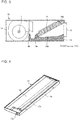
- Fig. 2 is a perspective view of the indoor unit 9 of the air-conditioning apparatus 100 according to Embodiment 1 of the present invention.
- the indoor unit 9 of the air-conditioning apparatus 100 is a ceiling mounted indoor unit mounted on the ceiling of a room.
- the indoor unit 9 of the air-conditioning apparatus 100 includes a unit body 10 and a storage box 20.
- the unit body 10 is a rectangular cuboid.
- an air inlet 11 is formed in an entire rear side surface of the unit body 10
- an air outlet 12 is formed in a front surface of the unit body 10 such that the air outlet 12 is slightly smaller than the entire front surface.
- the storage box 20 is attached to an outer wall of the unit body 10, which is located on a side thereof which corresponds to an upper side of Fig. 2 .
- Fig. 3 is a vertical cross-sectional view of the indoor unit 9 of the air-conditioning apparatus 100 according to Embodiment 1 of the present invention, which is taken along line A-A in Fig. 2 .
- Fig. 4 is a perspective view of a drain pan 13 in Embodiment 1 of the present invention.
- the unit body 10 includes the indoor heat exchanger 5, the sirocco fan 7, and the drain pan 13. As illustrated in Fig. 7 , which will be described later, the unit body 10 further includes a drain pump 14 and a float switch 15.
- the indoor heat exchanger 5 is formed in the shape of a thin plate.
- the indoor heat exchanger 5 is held by a support portion 10a and a raised portion 13a of the drain pan 13.
- the support portion 10a is located at an inner upper portion of the unit body 10 and close to the air outlet 12, and the raised portion 13a is located at an inner lower portion of the unit body 10.
- the indoor heat exchanger 5 is inclined in the unit body 10 such that a front portion of the indoor heat exchanger 5 is located at a high level and a rear portion of the indoor heat exchanger 5 is located at a low level, that is, flat surfaces of the indoor heat exchanger 5 are inclined, as illustrated in the vertical cross-sectional view.
- the indoor heat exchanger 5 is connected to a refrigerant pipe (not illustrated).
- the indoor heat exchanger 5 transfers heat between refrigerant that flows in the refrigerant pipe and air that flows in the unit body 10.
- the refrigerant pipe allows the refrigerant to flow from the outdoor unit 8 to the indoor heat exchanger 5.
- the sirocco fan 7 is located closer to the rear side of the unit body 10 than the indoor heat exchanger 5 in the unit body 10 and in parallel with the indoor heat exchanger 5 in a horizontal direction.
- the sirocco fan 7 sends air taken from indoor space through the air inlet 11 to the indoor heat exchanger 5.
- the air sent to the indoor heat exchanger 5 exchanges heat with the refrigerant that flows in the refrigerant pipe and then in the indoor heat exchanger 5.
- Conditioned air subjected to heat exchange in the indoor heat exchanger 5 is blown out of the indoor heat exchanger 5 through the air outlet 12 located in front of the indoor heat exchanger 5.
- the drain pan 13 is located at the lowest position in the unit body 10. Also, the drain pan 13 is provided to extend over an area that is located below the indoor heat exchanger 5 and the refrigerant pipe (not illustrated) and corresponds to the total area of the indoor heat exchanger 5 and the refrigerant pipe.
- the drain pan 13 receives water of condensation which is produced by condensation that occurs when the air is rapidly cooled by the refrigerant that passes through the indoor heat exchanger 5 or the refrigerant pipe.
- the drain pan 13 includes wall portions 13b at four sides of the drain pan 13.
- the drain pan 13 includes a natural outlet 13c through which drain water flows out of the drain pan 13 to the outside thereof.
- water of condensation is received in the drain pan 13 and collected as drain water in the drain pan 13, and the drain water flows out of the drain pan 13 through the natural outlet 13c.
- the natural outlet 13c is located on a lower side of Fig. 4 , it is located close to the storage box 20 on the upper side of Fig. 2 .
- Water of condensation that is produced at the indoor heat exchanger 5 or the refrigerant pipe drops onto a reception surface 13d of the drain pan 13 and is collected as drain water.
- the reception surface 13d of the drain pan 13 is inclined such that the natural outlet 13c is located at the lowest position. Because of this configuration, even if dropping at any position on the drain pan 13, water of condensation finally reaches as drain water the natural outlet 13c, and naturally flows out of the drain pan 13 through the natural outlet 13c.
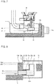
- Fig. 5 is an enlarged vertical sectional view of part of the indoor unit 9 that includes the natural outlet 13c in the air-conditioning apparatus 100 according to Embodiment 1 of the present invention. As illustrated in Fig. 5 , a lowermost portion of the natural outlet 13c is located at the reception surface 13d of the drain pan 13. In Fig. 5 , a dashed line indicates an L-shaped socket 22 which will be described later and is provided to communicate with the natural outlet 13c.
- Fig. 6 is a perspective view of the storage box 20 in Embodiment 1 of the present invention and illustrates an internal configuration of the storage box 20. As illustrated in Fig. 6 , the storage box 20 includes a sensor 21 and the L-shaped socket 22.
- the storage box 20 has an opening portion 23 that serves as a communication portion having no wall and is formed in part of the storage box 20 that is attached to an outer wall portion of the unit body 10. A surrounding portion of the opening portion 23 of the storage box 20 is in tightly fixed to the outer wall portion of the unit body 10.
- the storage box 20 stores refrigerant leaking from the unit body 10. Thereby, the refrigerant stored in the storage box 20 is prevented from flowing out of the storage box 20 to the outside. Furthermore, the sensor 21 detects the refrigerant with a higher accuracy.
- the sensor 21 detects refrigerant leaking from the unit body 10.
- the sensor 21 is attached to an inner wall portion of the storage body 20 that is located at an innermost part of the storage box 20 and faces the opening portion 23 of the storage box 20.
- the opening portion 23 communicates with the unit body 10.
- the refrigerant leaking from the unit body 10 flows toward the sensor 21 through the opening portion 23.
- the L-shaped socket 22 is a tubular element and allows the inside of the unit body 10 and the inside of the storage box 20 to communicate with each other via the opening portion 23.
- the L-shaped socket 22 includes a horizontal tube portion 22a and a vertical tube portion 22b.
- the horizontal tube portion 22a extends from the natural outlet 13c to the unit body 10 and opens to the unit body 10.
- the vertical tube portion 22b extends upwards from an end of the horizontal tube portion 22a that is located in the storage box 20, and has an opening at its upper end, that is, the L-shaped socket 22 is bent upwards at the end of the horizontal tube portion 22a.
- Fig. 7 is a perspective view illustrating the drain pan 13, the drain pump 14, and the float switch 15 in Embodiment 1 of the present invention, and illustrates a positional relationship in level between the drain pan 13, the drain pump 14, and the float switch 15.
- the unit body 10 includes the drain pump 14 and the float switch 15.
- the drain pump 14 is located above the drain pan 13.
- the drain pump 14 sucks drain water collected in the drain pan 13 during an operation of the air-conditioning apparatus 100 and discharges the drain water to the outside of the unit body 10.
- the float switch 15 is a component of the drain pump 14.
- the float switch 15 detects that a water level of the drain water collected in the drain pan 13 reaches a detection water level 16 which is a constant value.
- the float switch 15 detects that the drain water reaches the detection water level 16, the operation of the air-conditioning apparatus 100 is stopped.
- the drain water collects up to an operation water level 17, at which the drain pump 14 can suck the drain water, at the drain pan 13.
- the float switch 15 prevents the drain water from overflowing from the drain pan 13 because of an increase in the water level of the drain water, which would be caused by, for example, a failure of the drain pump 14 during the operation of the air-conditioning apparatus 100.
- the drain pump 14 is provided, and the drain pan 13 includes the natural outlet 13c, which is an already available drain outlet. Since the drain pan 13 having such a natural outlet 13c is used, it can be manufactured as a general component, regardless of the drain pump 14 is provided or not. It is therefore possible to reduce the manufacturing cost.
- Fig. 8 is a vertical sectional view illustrating the storage box 20 and part of the unit body 10 that adjoins the storage box 20 in Embodiment 1 of the present invention.
- the storage box 20 is attached to an outer wall portion 10b of a side of the unit body 10, in order that refrigerant leaking from the unit body 10 be collected.
- An opening portion of the horizontal tube portion 22a of the L-shaped socket 22 is connected with the natural outlet 13c of the drain pan 13.
- the L-shaped socket 22 serves as a passage to introduce the refrigerant leaking from the unit body 10 into the storage box 20.
- the natural outlet 13c communicates with the storage box 20 via the opening portion 23.
- the sensor 21 is provided to detect refrigerant flowing in the L-shaped socket 22.
- the refrigerant has a greater specific gravity than air. Therefore, the refrigerant leaking from, for example, the refrigerant pipe, falls and collects in the drain pan 13 located in the lower portion of the unit body 10.
- the L-shaped socket 22, which is tubular, is attached to the natural outlet 13c of the drain pan 13, thereby forming a refrigerant passage. Thereby, the refrigerant leaking in the unit body 10 flows through the L-shaped socket 22 and collects in the storage box 20.
- the sensor 21 detects the refrigerant in the storage box 20. As a result, it can be detected that the refrigerant leaks from, for example, the refrigerant pipe.
- the shape of the L-shaped socket 22 is determined based on the relationship between the amount of water of condensation that is produced at the indoor heat exchanger 5 or the refrigerant pipe, the shape of the drain pan 13, and the detection water level 16 for the float switch 15. It should be noted that if the L-shaped socket 22 were not provided, the drain water would flow through the natural outlet 13c into the storage box 20 attached to the outer wall portion of the unit body 10, and collect in the storage box 20, and then adheres to the sensor 21. In contrast, in Embodiment 1, the L-shaped socket 22 is provided, and the vertical tube portion 22b of the L-shaped socket 22 serves as a wall that prevents leakage of the drain water at the operation water level 17.
- the drain water that collects in the drain pan 13 during the operation of the air-conditioning apparatus 100 does not flow out of the indoor unit 9 at the operation water level 17. Furthermore, the drain water collecting in the drain pan 13 does not directly flow into the storage box 20 through the natural outlet 13c. Thus, the drain water does not reach the sensor 21.
- the upper end of the vertical tube portion 22b of the L-shaped socket 22 is located at a level 22b1, which is set higher than the operation water level 17 at which the drain pump 14 can suck the drain water, and preferably, should be set higher than the detection water level 16 for the float switch 15, and is also set lower than a height 13b1 of a wall portion 13b of the drain pan 13.
- the drain water that collects in the drain pan 13 does not flow over the upper end of the vertical tube portion 22b of the L-shaped socket 22 into the storage box 20, and thus does not reach the sensor 21.
- the level 22b1 of the upper end of the vertical tube portion 22b of the L-shaped socket 22 is set lower than the height 13b1 of the wall portion 13b of the drain pan 13. Therefore, the refrigerant that leaks from, for example, the refrigerant pipe, and collects in the drain pan 13 flows into the storage box 20 through the L-shaped socket 22, that is, it does not flow over the drain pan 13, and collects in the storage box 20. Thus, leakage refrigerant can be detected by the sensor 21.
- the indoor unit 9 is a unit device of the refrigeration cycle apparatus, and forms part of the refrigerant circuit that uses the flammable or slightly flammable refrigerant.
- the indoor unit 9 includes the unit body 10 and the storage box 20.
- the sensor 21 is provided to detect leakage of the refrigerant.
- the storage box 20 has the opening portion 23 that serves as a communicating portion communicating with the unit body 10.
- the storage box 20 is attached to the outer wall portion 10b of the unit body 10.
- the sensor 21 that detects leakage of the refrigerant is provided in the storage box 20 attached to the outer wall portion 10b of the unit body 10. Therefore, the unit body 10 does not need space for provision of the sensor 21 that detects refrigerant in the unit body 10, and the sensor 21 can be provided without modifying the design of the unit body 10 for provision of the sensor 21.
- the sensor 21 is provided in the storage box 20, and droplets of water, for example, water of condensation that is produced in the unit body 10 do not adhere to the sensor 21. It is therefore possible to prevent occurrence of a failure in the sensor 21, which would be caused by water droplets.
- the sensor 21 is provided in the storage box 20 and is located outside the unit body 10. The maintenance of the sensor 21 is therefore easily carried out.
- the storage box 20 may have a communication portion other than the opening portion 23.
- the storage box may have a hole, as a communication portion, in a side wall portion of the storage box.
- the unit body 10 of the indoor unit 9 includes the drain pan 13 that receives water of condensation.
- the drain pan 13 has the natural outlet 13c for drain water.
- the natural outlet 13c communicates with the storage box 20 via the opening portion 23.
- the natural outlet 13c which is an already available drain outlet and provided in the drain pan 13 is used as an inlet through which leakage refrigerant flows into the storage box 20. Therefore, the unit body 10 having the natural outlet 13c is more effectively used without modifying the design of the unit body 10.
- the indoor unit 9 includes the L-shaped socket 22 as a socket that communicates with the unit body 10 and the storage box 20 via the opening portion 23.
- the L-shaped socket 22 communicates with the unit body 10 and the storage box 20.
- the L-shaped socket 22 allows the refrigerant leaking from the unit body 10 to flow toward the sensor 21.
- the L-shaped socket 22 includes the horizontal tube portion 22a that is connected with the natural outlet 13c and opens to the unit body 10, and the vertical tube portion 22b that extends upwards from the end of the horizontal tube portion 22a, which is located in the storage box 20, and that has an opening at its upper end.
- An upper end portion of the vertical tube portion 22b is located at the level 22b1, which is higher than the operation water level 17 at which the drain pump 14 can suck the drain water and is lower than an upper end portion of the wall portion 13b of the drain pan 13.
- the L-shaped socket 22 communicates with the unit body 10 and the storage box 20 via the natural outlet 13c. Therefore, the L-shaped socket 22 allows the refrigerant leaking from the unit body 10 to flow toward the sensor 21 such that the refrigerant flows over the drain water collecting in the natural outlet 13c.
- the sensor 21 can early detect the leakage refrigerant on the drain water received in the drain pan 13.
- the upper end portion of the vertical tube portion 22b is located at a higher level than the operation water level 17 at which the drain pump 14 can suck the drain water, the drain water that collects in the drain pan 13 in the operation of the air-conditioning apparatus 100 does not overflow from the drain pan 13 at the operation water level 17.
- the refrigerant leaking from, for example, the refrigerant pipe flows over the drain water that collects in the drain pan 13 at the operation water level 17, flows through the L-shaped socket 22, then flows into the storage box 20, and can thus be detected by the sensor 21.
- the refrigerant leaking from, for example, the refrigerant pipe, and collecting in the drain pan 13 can be detected by the sensor 21 before overflowing the drain pan 13.
- the socket 22 is not limited the L-shaped socket. As the socket 22, any socket can be used as long as it is formed to communicate with the unit body 10 and the storage box 20.
- the indoor unit 9 is an indoor unit of the air-conditioning apparatus 100 and includes the indoor heat exchanger 5, the refrigerant pipe that allows the refrigerant to flow in the indoor heat exchanger 5, and the sirocco fan 7 that sends air to the indoor heat exchanger 5, such that the indoor heat exchanger 5, the refrigerant pipe and the sirocco fan 7 are provided in the unit body 10.
- the indoor unit 9 of the air-conditioning apparatus 100 does not need space for provision of the sensor 21 that detects refrigerant in the unit body 10, and the sensor 21 can be attached without modifying the unit body 10.
- the indoor unit 9 is a ceiling mounted indoor unit attached to the ceiling of a room.
- the ceiling mounted indoor unit 9 of the air-conditioning apparatus 100 does not need space for provision of the sensor 21 that detects refrigerant in the unit body 10, and the sensor 21 can be attached without modifying the design of the unit body 10.
- leakage refrigerant can be detected by the sensor 21 before falling into the room and flying off in the room.
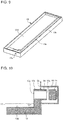
- Fig. 9 is a perspective view of the drain pan 13 in Embodiment 2 of the present invention.
- Fig. 10 is a vertical sectional view illustrating the storage box 20 and part of the unit body 10 that adjoins the storage box 20 in Embodiment 2 of the present invention.
- Embodiment 2 the same descriptions as made regarding Embodiment 1 will be omitted, and only features of Embodiment 2 which are different from those of Embodiment 1 will be described.
- the drain pan has a ventilation hole 13e that differs from a drain outlet.
- the ventilation hole 13e is provided in the wall portion 13b of the drain pan 13 as a ventilation not intended for drainage.
- the refrigerant leaking from, for example, the refrigerant pipe and collecting in the drain pan 13 flows into the storage box 20 through the ventilation hole 13e.
- the ventilation hole 13e communicates with the storage box 20 via the opening portion 23, and the sensor 21 can thus detect the refrigerant flowing into the storage box 20 through the ventilation hole 13e.
- a tubular socket 24 is attached to the ventilation hole 13e formed in the wall portion 13b of the drain pan 13.
- the refrigerant leaking from the refrigerant pipe collects in the drain pan 13, flows through the socket 24, and is then detected by the sensor 21, as in Embodiment 1.
- the ventilation hole 13e formed in the wall portion 13b of the drain pan 13 is located at a level that is higher level than the operation water level 17 at which the drain pump 14 can suck the drain water, and preferably should be higher than the detection water level 16 of the float switch 15, and is also lower than the upper end portion of the wall portion 13b of the drain pan 13.
- the tubular socket 24 can be formed to have a simple configuration and a smaller size. In such a manner, since the socket 24 is formed to have a smaller size, the distance between the sensor 21 and an end 24a of the socket 24 that is located in the storage box 20 is shortened. Since the distance is shortened, the sensor 21 can earlier detect the refrigerant flowing through the socket 24.
- the unit body 10 of the indoor unit 9 includes the drain pan 13 that receives water of condensation.
- the drain pan 13 has the ventilation hole 13e.
- the ventilation hole 13e communicates with the storage box 20 via the opening portion 23.
- the ventilation hole 13e is located at a level higher than the operation water level 17, at which the drain pump 14 can suck the drain water, and lower than the upper end portion of the wall portion 13b of the drain pan 13.
- the ventilation hole 13e of the drain pan 13 is used as an inlet through which leakage refrigerant flows into the storage box 20. Therefore, the unit body 10 having the ventilation hole 13e can be more effectively used without modifying the design of the unit body 10.
- the drain water that collects in the drain pan 13 in the operation of the air-conditioning apparatus 100 does not overflow from the drain pan 13 at the operation water level 17, at which the drain pump 14 can suck the drain water.
- the refrigerant leaking from, for example, the refrigerant pipe flows over the drain water that collects in the drain pan 13 at the operation water level 17, flows into the storage box 20 through the ventilation hole 13e and the socket 24, and can be detected by the sensor 21.
- the refrigerant leaking from, for example, the refrigerant pipe and collecting in the drain pan 13 can be detected by the sensor 21 before overflowing from the drain pan 13.
- Fig. 11 is a vertical sectional view illustrating the storage box 20 and part of the unit body 10 that adjoins the storage box 20 in a first configuration example of Embodiment 3 of the present invention.
- first configuration example of Embodiment 3 the same descriptions as made regarding the above embodiments will be omitted, and only features of the first configuration example of Embodiment 3 which are different from those of the above embodiments will be described.
- the drain pan 13 has a flow passage 13f that extends to the storage box 20 and serves as a communication portion communicating with the storage box 20 and the unit body 10 via the opening portion 23.
- the flow passage 13f is a tubular portion and formed integrally with the drain pan 13.
- the flow passage 13f that is formed to project from the wall portion 13b of the drain pan 13 is located at a level that is higher than the operation water level 17 at which the drain pump 14 can suck the drain water, and preferably should be higher than the detection water level 16 of the float switch 15, and is also lower than the upper end portion of the wall portion 13b of the drain pan 13.
- the flow passage 13f is provided to cause the refrigerant on the drain water in the drain pan 13 to flow directly to the sensor 21. Thereby, the distance between the sensor 21 and an outlet portion of the flow passage 13f is shortened, and leakage of the refrigerant can thus be rapidly detected. Furthermore, the flow passage 13f is provided far away from an electrical component box (not illustrated) provided in the unit body 10. Thereby, the refrigerant flowing through the flow passage 13f is located far away from the electrical component box, thus preventing ignition of the flammable or slightly flammable refrigerant.
- Fig. 12 is a vertical sectional view illustrating the storage box 20 and part of the unit body 10 that adjoins the storage box 20 in a second configuration example of Embodiment 3 of the present invention.
- the second configuration example of Embodiment 3 descriptions concerning components which are the same as those of the above Embodiments will be omitted, and only a feature of the second configuration which are not included in the Embodiments will be described.
- the feature of the flow passage 13f which allows the refrigerant to flow therethrough varies in accordance with the shape of the flow passage 13f.
- the outlet portion of the flow passage 13f which is located in the storage box 20, is inclined downwards.
- the refrigerant is heavier than air, and thus flows downwards to the right side of Fig. 12 along the inclined part of the flow passage 13f and then reaches the sensor 21.
- the refrigerant reaches the sensor 21 for a shorter time period.
- the refrigerant can thus be earlier detected by the sensor 21.
- Fig. 13 is a vertical sectional view illustrating the storage box 20 and part of the unit body 10 that adjoins the storage box 20 in a third configuration example of Embodiment 3 of the present invention.
- the same descriptions as made regarding the above embodiments will be omitted, and only a feature of the third configuration example of Embodiment 3 which are different from those of the embodiments will be described.
- the outlet portion of the flow passage 13f that is located in the storage box 20 is inclined upwards. In such a case, water of condensation that is produced during the operation of the air-conditioning apparatus 100 does not flow from the drain pan 13 into the storage box 20 through the flow passage 13f.
- the sirocco fan 7 causes the drain water that collects in the drain pan 13 to spatter.
- the spattering drain water does not enter the storage box 20 because of provision of the flow passage 13f that is inclined upwards toward the right side of Fig. 13 .
- the drain pan 13 has the flow passage 13f that extends to the storage box 20 and communicates with the unit body 10 and the storage box 20 via the opening portion 23 that serves as communicating portion.
- the flow passage 13f extending from the drain pan 13 to the storage box 20 communicates with the unit body 10 and the storage box 20.
- the flow passage 13f allows the refrigerant leaking from the unit body 10 to flow to the sensor 21.
- Fig. 14 is a vertical sectional view illustrating the storage box 20 and part of the unit body 10 that adjoins the storage box 20 in Embodiment 4 of the present invention.
- Embodiment 4 the same descriptions as made above regarding the above embodiments will be omitted, and only features of Embodiment 4 that are different from those of the embodiments will be described.
- a hole is formed as a vent 10C in the outer wall portion 10b of the unit body 10, to which the storage box 20 is attached.
- the vent 10c communicates with an inner space of the unit body 10 and an inner space of the storage box 20.
- the vent 10c communicates with the storage box 20 via the opening portion 23.
- the vent 10c of the outer wall portion 10b is located at a level higher than the drain pan 13.
- the sensor 21 is provided on an imaginary line extending inwardly from the vent 10c to an inner part of the storage box 20.
- a ventilation hole 13g is formed in the drain pan 13.
- the ventilation hole 13g may be any of the natural outlet 13c, the L-shaped socket 22, the ventilation hole 13e provided in the wall portion 13b of the drain pan 13, and the flow passage 13f formed integral with the drain pan 13 and allowing the refrigerant to flow, which are all described with respect to the above embodiments.
- the indoor unit 9 has the vent 10c communicating with the inner space of the unit body 10 and the inner space of the storage box 20.
- the vent 10c communicates with the storage box 20 via the opening portion 23.
- vent 10c since the vent 10c communicates with the inner space of the unit body 10 and the inner space of the storage box 20, the vent 10c allows the refrigerant leaking from the unit body 10 to flow toward the sensor 21 provided in the storage box 20.
- the above embodiments are described above by referring to by way of example the case where the storage box is attached to the wall portion of the unit body, which forms a side of the unit body.
- the storage box may be attached to a lower surface of the unit body.
- the storage box may be attached to the lower surface of the unit body such that the refrigerant that overflows from the drain pan can be detected.
- each of the embodiments is applied to an indoor unit of an air-conditioning apparatus.
- this is not limitative.
- each embodiment may be applied to an outdoor unit of an air-conditioning apparatus.
- each embodiment may be applied to refrigeration cycle apparatuses other than an air-conditioning apparatus, for example, a refrigeration apparatus and a water heater.
Landscapes
- Engineering & Computer Science (AREA)
- Mechanical Engineering (AREA)
- General Engineering & Computer Science (AREA)
- Physics & Mathematics (AREA)
- Thermal Sciences (AREA)
- Chemical & Material Sciences (AREA)
- Combustion & Propulsion (AREA)
- Devices For Blowing Cold Air, Devices For Blowing Warm Air, And Means For Preventing Water Condensation In Air Conditioning Units (AREA)
- Air Conditioning Control Device (AREA)
Abstract
Description
- The present invention relates to a unit device of a refrigeration cycle apparatus. The unit device forms part of a refrigerant circuit using flammable or slightly flammable refrigerant, and includes a sensor that detects leakage of the refrigerant.
- In recent years, there has been a trend toward usage of alternatives to chlorofluorocarbons as refrigerants for refrigeration cycle apparatuses in countermeasures against environmental problems, such as global warming and ozone depletion. Examples of these alternatives include R32. Such a refrigerant used in the countermeasures against environmental problems is flammable or slightly flammable. If this refrigerant leaks out of a unit device, the refrigerant may ignite, causing a fire.
- A unit device of an existing refrigeration cycle apparatus includes a sensor that detects leakage of refrigerant, and the sensor is provided in close to a drain pan. When the sensor detects leakage of the refrigerant in the unit device, an operation of the refrigeration cycle apparatus is stopped to avoid a fire (see, for example, Patent Literature 1).
- Patent Literature 1: Japanese Unexamined Patent Application Publication No.
2002-98346 - As described in Patent Literature 1, in general, a sensor that detects refrigerant is attached to the inside of a unit device of a refrigeration cycle apparatus. Therefore, when such a unit device of a refrigeration cycle apparatus is newly developed, it is designed on the premise that space for a sensor that detects refrigerant is provided in the unit device.
- Furthermore, in a unit device of an existing refrigeration cycle apparatus using nonflammable chlorofluorocarbon as refrigerant, in the case where the refrigerant is replaced by a refrigerant corresponding to an alternative to chlorofluorocarbon, it is necessary to attach a sensor that detects a flammable or slightly flammable refrigerant to the unit device. However, the unit device of the existing refrigeration cycle apparatus has no space for provision of the refrigerant sensor and thus needs to be greatly modified.
- The flammable or slightly flammable refrigerant has a specific gravity greater than air. The refrigerant sensor, therefore, needs to be provided below a refrigerant pipe from which the refrigerant may leak. However, droplets of water of, for example, condensation which is produced during an operation of the refrigeration cycle apparatus, may adhere to the sensor, thus causing occurrence of a failure in the sensor.
- The present invention has been made to solve the above problems, and aims to provide a unit device of a refrigeration cycle apparatus in which space for provision of a sensor that detects refrigerant does not need to be provided in a unit body of the unit device and in which the sensor is connected to the unit body without modifying the design of the unit body for provision of the sensor.
- A unit device of a refrigeration cycle apparatus, according to an embodiment of the present invention, is a unit device that forms part of a refrigerant circuit using flammable or slightly flammable refrigerant, and that includes a unit body and a storage box. The storage box provided with a sensor that detects leakage of the refrigerant and a communicating portion that communicates with the unit body. The storage box is attached to an outer wall portion of the unit body.
- In the unit device of the refrigeration cycle apparatus, according to the embodiment of the present invention, the storage box is attached to the outer wall portion of the unit body. Therefore, it is not necessary to provide in the unit body, space for provision of the sensor, and it is possible to attach the sensor to the unit body without modifying the design of the unit body for attachment of the sensor.
-
- [
Fig. 1] Fig. 1 is a schematic diagram illustrating a configuration example of an air-conditioning apparatus according to Embodiment 1 of the present invention. - [
Fig. 2] Fig. 2 is a perspective view of an indoor unit of the air-conditioning apparatus according to Embodiment 1 of the present invention. - [
Fig. 3] Fig. 3 is a vertical cross-sectional view of the indoor unit of the air-conditioning apparatus according to Embodiment 1 of the present invention, which is taken along line A-A inFig. 2 . - [
Fig. 4] Fig. 4 is a perspective view of a drain pan in Embodiment 1 of the present invention. - [
Fig. 5] Fig. 5 is an enlarged vertical sectional view of part of the indoor unit of the air-conditioning apparatus according to Embodiment 1 of the present invention, which includes a natural discharge outlet. - [
Fig. 6] Fig. 6 is a perspective view of a storage box in Embodiment 1 of the present invention and illustrates an internal configuration of the storage box. - [
Fig. 7] Fig. 7 is a perspective view illustrating the drain pan, a drain pump, and a float switch in Embodiment 1 of the present invention and indicates a positional relationship in level between the drain pan, the drain pump, and the float switch. - [
Fig. 8] Fig. 8 is a vertical sectional view illustrating the storage box and part of a unit body that adjoins the storage box in Embodiment 1 of the present invention. - [
Fig. 9] Fig. 9 is a perspective view of the drain pan inEmbodiment 2 of the present invention. - [
Fig. 10] Fig. 10 is a vertical sectional view illustrating the storage box and part of the unit body that adjoins the storage box inEmbodiment 2 of the present invention. - [
Fig. 11] Fig. 11 is a vertical sectional view illustrating the storage box and part of the unit body that adjoins the storage box in a first configuration example of Embodiment 3 of the present invention. - [
Fig. 12] Fig. 12 is a vertical sectional view illustrating the storage box and part of the unit body that adjoins the storage box in a second configuration example of Embodiment 3 of the present invention. - [
Fig. 13] Fig. 13 is a vertical sectional view illustrating the storage box and part of the unit body that adjoins the storage box in a third configuration example of Embodiment 3 of the present invention. - [
Fig. 14] Fig. 14 is a vertical sectional view illustrating the storage box and part of the unit body that adjoins the storage box in Embodiment 4 of the present invention. Description of Embodiments - The embodiments of the present invention will be described below with reference to the drawings. It should be noted that in each of the figures in the drawings, components which are the same as or equivalent to those in a previous figure are denoted by the same reference signs. Furthermore, the forms of the components referred to in the entire text of the specification are described by way of example, and are not limited to those described in the entire text.
-
Fig. 1 is a schematic diagram of a configuration of an air-conditioning apparatus 100 according to Embodiment 1 of the present invention. As illustrated inFig. 1 , in the air-conditioning apparatus 100, anoutdoor unit 8 and anindoor unit 9 are connected by pipes. - The pipes connecting the
outdoor unit 8 and theindoor unit 9 are filled with refrigerant for heat transfer and reception. The refrigerant is circulated between theoutdoor unit 8 and theindoor unit 9 to perform cooling or heating on space in which theindoor unit 9 is installed. As the refrigerant, for example, a flammable or slightly flammable refrigerant that is an alternative to chlorofluorocarbon, such as R32, is used. - The
outdoor unit 8 includes a compressor 1, an outdoor heat exchanger 3, an expansion valve 4, a four-way valve 2, and anoutdoor fan 6. Theindoor unit 9 includes anindoor heat exchanger 5 and asirocco fan 7 that operates as an indoor fan. -
Fig. 2 is a perspective view of theindoor unit 9 of the air-conditioning apparatus 100 according to Embodiment 1 of the present invention. As illustrated inFig. 2 , theindoor unit 9 of the air-conditioning apparatus 100 is a ceiling mounted indoor unit mounted on the ceiling of a room. Theindoor unit 9 of the air-conditioning apparatus 100 includes aunit body 10 and astorage box 20. - As illustrated in
Fig. 2 , theunit body 10 is a rectangular cuboid. In theunit body 10, anair inlet 11 is formed in an entire rear side surface of theunit body 10, and anair outlet 12 is formed in a front surface of theunit body 10 such that theair outlet 12 is slightly smaller than the entire front surface. - As illustrated in
Fig. 2 , thestorage box 20 is attached to an outer wall of theunit body 10, which is located on a side thereof which corresponds to an upper side ofFig. 2 . -
Fig. 3 is a vertical cross-sectional view of theindoor unit 9 of the air-conditioning apparatus 100 according to Embodiment 1 of the present invention, which is taken along line A-A inFig. 2 .Fig. 4 is a perspective view of adrain pan 13 in Embodiment 1 of the present invention. - As illustrated in
Fig. 3 , theunit body 10 includes theindoor heat exchanger 5, thesirocco fan 7, and thedrain pan 13. As illustrated inFig. 7 , which will be described later, theunit body 10 further includes adrain pump 14 and afloat switch 15. - As illustrated in
Fig. 3 , theindoor heat exchanger 5 is formed in the shape of a thin plate. Theindoor heat exchanger 5 is held by asupport portion 10a and a raisedportion 13a of thedrain pan 13. Thesupport portion 10a is located at an inner upper portion of theunit body 10 and close to theair outlet 12, and the raisedportion 13a is located at an inner lower portion of theunit body 10. Thus, theindoor heat exchanger 5 is inclined in theunit body 10 such that a front portion of theindoor heat exchanger 5 is located at a high level and a rear portion of theindoor heat exchanger 5 is located at a low level, that is, flat surfaces of theindoor heat exchanger 5 are inclined, as illustrated in the vertical cross-sectional view. Theindoor heat exchanger 5 is connected to a refrigerant pipe (not illustrated). Theindoor heat exchanger 5 transfers heat between refrigerant that flows in the refrigerant pipe and air that flows in theunit body 10. The refrigerant pipe allows the refrigerant to flow from theoutdoor unit 8 to theindoor heat exchanger 5. - As illustrated in
Fig. 3 , thesirocco fan 7 is located closer to the rear side of theunit body 10 than theindoor heat exchanger 5 in theunit body 10 and in parallel with theindoor heat exchanger 5 in a horizontal direction. Thesirocco fan 7 sends air taken from indoor space through theair inlet 11 to theindoor heat exchanger 5. The air sent to theindoor heat exchanger 5 exchanges heat with the refrigerant that flows in the refrigerant pipe and then in theindoor heat exchanger 5. Conditioned air subjected to heat exchange in theindoor heat exchanger 5 is blown out of theindoor heat exchanger 5 through theair outlet 12 located in front of theindoor heat exchanger 5. - As illustrated in
Fig. 3 , thedrain pan 13 is located at the lowest position in theunit body 10. Also, thedrain pan 13 is provided to extend over an area that is located below theindoor heat exchanger 5 and the refrigerant pipe (not illustrated) and corresponds to the total area of theindoor heat exchanger 5 and the refrigerant pipe. Thedrain pan 13 receives water of condensation which is produced by condensation that occurs when the air is rapidly cooled by the refrigerant that passes through theindoor heat exchanger 5 or the refrigerant pipe. - As illustrated in
Fig. 4 , thedrain pan 13 includeswall portions 13b at four sides of thedrain pan 13. Thedrain pan 13 includes anatural outlet 13c through which drain water flows out of thedrain pan 13 to the outside thereof. To be more specific, water of condensation is received in thedrain pan 13 and collected as drain water in thedrain pan 13, and the drain water flows out of thedrain pan 13 through thenatural outlet 13c. Although thenatural outlet 13c is located on a lower side ofFig. 4 , it is located close to thestorage box 20 on the upper side ofFig. 2 . Water of condensation that is produced at theindoor heat exchanger 5 or the refrigerant pipe drops onto areception surface 13d of thedrain pan 13 and is collected as drain water. Thereception surface 13d of thedrain pan 13 is inclined such that thenatural outlet 13c is located at the lowest position. Because of this configuration, even if dropping at any position on thedrain pan 13, water of condensation finally reaches as drain water thenatural outlet 13c, and naturally flows out of thedrain pan 13 through thenatural outlet 13c. -
Fig. 5 is an enlarged vertical sectional view of part of theindoor unit 9 that includes thenatural outlet 13c in the air-conditioning apparatus 100 according to Embodiment 1 of the present invention. As illustrated inFig. 5 , a lowermost portion of thenatural outlet 13c is located at thereception surface 13d of thedrain pan 13. InFig. 5 , a dashed line indicates an L-shapedsocket 22 which will be described later and is provided to communicate with thenatural outlet 13c. -
Fig. 6 is a perspective view of thestorage box 20 in Embodiment 1 of the present invention and illustrates an internal configuration of thestorage box 20. As illustrated inFig. 6 , thestorage box 20 includes asensor 21 and the L-shapedsocket 22. - As illustrated in
Fig. 6 , thestorage box 20 has an openingportion 23 that serves as a communication portion having no wall and is formed in part of thestorage box 20 that is attached to an outer wall portion of theunit body 10. A surrounding portion of the openingportion 23 of thestorage box 20 is in tightly fixed to the outer wall portion of theunit body 10. Thestorage box 20 stores refrigerant leaking from theunit body 10. Thereby, the refrigerant stored in thestorage box 20 is prevented from flowing out of thestorage box 20 to the outside. Furthermore, thesensor 21 detects the refrigerant with a higher accuracy. - The
sensor 21 detects refrigerant leaking from theunit body 10. Thesensor 21 is attached to an inner wall portion of thestorage body 20 that is located at an innermost part of thestorage box 20 and faces the openingportion 23 of thestorage box 20. The openingportion 23 communicates with theunit body 10. Thus, the refrigerant leaking from theunit body 10 flows toward thesensor 21 through the openingportion 23. - The L-shaped
socket 22 is a tubular element and allows the inside of theunit body 10 and the inside of thestorage box 20 to communicate with each other via the openingportion 23. The L-shapedsocket 22 includes ahorizontal tube portion 22a and avertical tube portion 22b. Thehorizontal tube portion 22a extends from thenatural outlet 13c to theunit body 10 and opens to theunit body 10. Thevertical tube portion 22b extends upwards from an end of thehorizontal tube portion 22a that is located in thestorage box 20, and has an opening at its upper end, that is, the L-shapedsocket 22 is bent upwards at the end of thehorizontal tube portion 22a. -
Fig. 7 is a perspective view illustrating thedrain pan 13, thedrain pump 14, and thefloat switch 15 in Embodiment 1 of the present invention, and illustrates a positional relationship in level between thedrain pan 13, thedrain pump 14, and thefloat switch 15. As illustrated inFig. 7 , theunit body 10 includes thedrain pump 14 and thefloat switch 15. - As illustrated in
Fig. 7 , thedrain pump 14 is located above thedrain pan 13. - The
drain pump 14 sucks drain water collected in thedrain pan 13 during an operation of the air-conditioning apparatus 100 and discharges the drain water to the outside of theunit body 10. - As illustrated in
Fig. 7 , thefloat switch 15 is a component of thedrain pump 14. Thefloat switch 15 detects that a water level of the drain water collected in thedrain pan 13 reaches adetection water level 16 which is a constant value. When thefloat switch 15 detects that the drain water reaches thedetection water level 16, the operation of the air-conditioning apparatus 100 is stopped. - As illustrated in
Fig. 7 , while the air-conditioning apparatus 100 is in operation, the drain water collects up to anoperation water level 17, at which thedrain pump 14 can suck the drain water, at thedrain pan 13. Thefloat switch 15 prevents the drain water from overflowing from thedrain pan 13 because of an increase in the water level of the drain water, which would be caused by, for example, a failure of thedrain pump 14 during the operation of the air-conditioning apparatus 100. It should be noted that in Embodiment 1, thedrain pump 14 is provided, and thedrain pan 13 includes thenatural outlet 13c, which is an already available drain outlet. Since thedrain pan 13 having such anatural outlet 13c is used, it can be manufactured as a general component, regardless of thedrain pump 14 is provided or not. It is therefore possible to reduce the manufacturing cost. -
Fig. 8 is a vertical sectional view illustrating thestorage box 20 and part of theunit body 10 that adjoins thestorage box 20 in Embodiment 1 of the present invention. As illustrated inFig. 8 , thestorage box 20 is attached to anouter wall portion 10b of a side of theunit body 10, in order that refrigerant leaking from theunit body 10 be collected. An opening portion of thehorizontal tube portion 22a of the L-shapedsocket 22 is connected with thenatural outlet 13c of thedrain pan 13. Thereby, the L-shapedsocket 22 serves as a passage to introduce the refrigerant leaking from theunit body 10 into thestorage box 20. In other words, thenatural outlet 13c communicates with thestorage box 20 via the openingportion 23. In thestorage box 20, thesensor 21 is provided to detect refrigerant flowing in the L-shapedsocket 22. - The refrigerant has a greater specific gravity than air. Therefore, the refrigerant leaking from, for example, the refrigerant pipe, falls and collects in the
drain pan 13 located in the lower portion of theunit body 10. In Embodiment 1, the L-shapedsocket 22, which is tubular, is attached to thenatural outlet 13c of thedrain pan 13, thereby forming a refrigerant passage. Thereby, the refrigerant leaking in theunit body 10 flows through the L-shapedsocket 22 and collects in thestorage box 20. Thesensor 21 detects the refrigerant in thestorage box 20. As a result, it can be detected that the refrigerant leaks from, for example, the refrigerant pipe. - The shape of the L-shaped
socket 22 is determined based on the relationship between the amount of water of condensation that is produced at theindoor heat exchanger 5 or the refrigerant pipe, the shape of thedrain pan 13, and thedetection water level 16 for thefloat switch 15. It should be noted that if the L-shapedsocket 22 were not provided, the drain water would flow through thenatural outlet 13c into thestorage box 20 attached to the outer wall portion of theunit body 10, and collect in thestorage box 20, and then adheres to thesensor 21. In contrast, in Embodiment 1, the L-shapedsocket 22 is provided, and thevertical tube portion 22b of the L-shapedsocket 22 serves as a wall that prevents leakage of the drain water at theoperation water level 17. Thereby, the drain water that collects in thedrain pan 13 during the operation of the air-conditioning apparatus 100 does not flow out of theindoor unit 9 at theoperation water level 17. Furthermore, the drain water collecting in thedrain pan 13 does not directly flow into thestorage box 20 through thenatural outlet 13c. Thus, the drain water does not reach thesensor 21. - As illustrated in
Fig. 8 , the upper end of thevertical tube portion 22b of the L-shapedsocket 22 is located at a level 22b1, which is set higher than theoperation water level 17 at which thedrain pump 14 can suck the drain water, and preferably, should be set higher than thedetection water level 16 for thefloat switch 15, and is also set lower than a height 13b1 of awall portion 13b of thedrain pan 13. When the drain water collects such that the level of the drain water is higher than or equal to thedetection water level 16 for thefloat switch 15 in thedrain pan 13, the operation of the air-conditioning apparatus 100 is stopped. Since the level 22b1 of the upper end of thevertical tube portion 22b of the L-shapedsocket 22 is higher than thedetection water level 16 for thefloat switch 15, the drain water that collects in thedrain pan 13 does not flow over the upper end of thevertical tube portion 22b of the L-shapedsocket 22 into thestorage box 20, and thus does not reach thesensor 21. - As illustrated in
Fig. 8 , the level 22b1 of the upper end of thevertical tube portion 22b of the L-shapedsocket 22 is set lower than the height 13b1 of thewall portion 13b of thedrain pan 13. Therefore, the refrigerant that leaks from, for example, the refrigerant pipe, and collects in thedrain pan 13 flows into thestorage box 20 through the L-shapedsocket 22, that is, it does not flow over thedrain pan 13, and collects in thestorage box 20. Thus, leakage refrigerant can be detected by thesensor 21. - In Embodiment 1, the
indoor unit 9 is a unit device of the refrigeration cycle apparatus, and forms part of the refrigerant circuit that uses the flammable or slightly flammable refrigerant. Theindoor unit 9 includes theunit body 10 and thestorage box 20. In thestorage box 20, thesensor 21 is provided to detect leakage of the refrigerant. Thestorage box 20 has the openingportion 23 that serves as a communicating portion communicating with theunit body 10. Thestorage box 20 is attached to theouter wall portion 10b of theunit body 10. - In the above configuration, the
sensor 21 that detects leakage of the refrigerant is provided in thestorage box 20 attached to theouter wall portion 10b of theunit body 10. Therefore, theunit body 10 does not need space for provision of thesensor 21 that detects refrigerant in theunit body 10, and thesensor 21 can be provided without modifying the design of theunit body 10 for provision of thesensor 21. In addition, thesensor 21 is provided in thestorage box 20, and droplets of water, for example, water of condensation that is produced in theunit body 10 do not adhere to thesensor 21. It is therefore possible to prevent occurrence of a failure in thesensor 21, which would be caused by water droplets. In addition, thesensor 21 is provided in thestorage box 20 and is located outside theunit body 10. The maintenance of thesensor 21 is therefore easily carried out. For example, in the case where a technician replaces thesensor 21 by a new one, he or she has only to detach thestorage box 20. That is, he or she can achieve the replacement of thesensor 21 at a high efficiency. Furthermore, thestorage box 20 may have a communication portion other than the openingportion 23. For example, the storage box may have a hole, as a communication portion, in a side wall portion of the storage box. - In Embodiment 1, the
unit body 10 of theindoor unit 9 includes thedrain pan 13 that receives water of condensation. Thedrain pan 13 has thenatural outlet 13c for drain water. Thenatural outlet 13c communicates with thestorage box 20 via the openingportion 23. - In such a configuration, the
natural outlet 13c which is an already available drain outlet and provided in thedrain pan 13 is used as an inlet through which leakage refrigerant flows into thestorage box 20. Therefore, theunit body 10 having thenatural outlet 13c is more effectively used without modifying the design of theunit body 10. - In Embodiment 1, the
indoor unit 9 includes the L-shapedsocket 22 as a socket that communicates with theunit body 10 and thestorage box 20 via the openingportion 23. - In the above configuration, the L-shaped
socket 22 communicates with theunit body 10 and thestorage box 20. Thus, the L-shapedsocket 22 allows the refrigerant leaking from theunit body 10 to flow toward thesensor 21. - In Embodiment 1, the L-shaped
socket 22 includes thehorizontal tube portion 22a that is connected with thenatural outlet 13c and opens to theunit body 10, and thevertical tube portion 22b that extends upwards from the end of thehorizontal tube portion 22a, which is located in thestorage box 20, and that has an opening at its upper end. An upper end portion of thevertical tube portion 22b is located at the level 22b1, which is higher than theoperation water level 17 at which thedrain pump 14 can suck the drain water and is lower than an upper end portion of thewall portion 13b of thedrain pan 13. - In the above configuration, the L-shaped
socket 22 communicates with theunit body 10 and thestorage box 20 via thenatural outlet 13c. Therefore, the L-shapedsocket 22 allows the refrigerant leaking from theunit body 10 to flow toward thesensor 21 such that the refrigerant flows over the drain water collecting in thenatural outlet 13c. Thus, thesensor 21 can early detect the leakage refrigerant on the drain water received in thedrain pan 13. Furthermore, since the upper end portion of thevertical tube portion 22b is located at a higher level than theoperation water level 17 at which thedrain pump 14 can suck the drain water, the drain water that collects in thedrain pan 13 in the operation of the air-conditioning apparatus 100 does not overflow from thedrain pan 13 at theoperation water level 17. Additionally, the refrigerant leaking from, for example, the refrigerant pipe, flows over the drain water that collects in thedrain pan 13 at theoperation water level 17, flows through the L-shapedsocket 22, then flows into thestorage box 20, and can thus be detected by thesensor 21. Thus, the refrigerant leaking from, for example, the refrigerant pipe, and collecting in thedrain pan 13 can be detected by thesensor 21 before overflowing thedrain pan 13. Thesocket 22 is not limited the L-shaped socket. As thesocket 22, any socket can be used as long as it is formed to communicate with theunit body 10 and thestorage box 20. - In Embodiment 1, the
indoor unit 9 is an indoor unit of the air-conditioning apparatus 100 and includes theindoor heat exchanger 5, the refrigerant pipe that allows the refrigerant to flow in theindoor heat exchanger 5, and thesirocco fan 7 that sends air to theindoor heat exchanger 5, such that theindoor heat exchanger 5, the refrigerant pipe and thesirocco fan 7 are provided in theunit body 10. - In such a configuration, the
indoor unit 9 of the air-conditioning apparatus 100 does not need space for provision of thesensor 21 that detects refrigerant in theunit body 10, and thesensor 21 can be attached without modifying theunit body 10. - In Embodiment 1, the
indoor unit 9 is a ceiling mounted indoor unit attached to the ceiling of a room. - In the above configuration, the ceiling mounted
indoor unit 9 of the air-conditioning apparatus 100 does not need space for provision of thesensor 21 that detects refrigerant in theunit body 10, and thesensor 21 can be attached without modifying the design of theunit body 10. As a result, leakage refrigerant can be detected by thesensor 21 before falling into the room and flying off in the room. -
Fig. 9 is a perspective view of thedrain pan 13 inEmbodiment 2 of the present invention.Fig. 10 is a vertical sectional view illustrating thestorage box 20 and part of theunit body 10 that adjoins thestorage box 20 inEmbodiment 2 of the present invention. RegardingEmbodiment 2, the same descriptions as made regarding Embodiment 1 will be omitted, and only features ofEmbodiment 2 which are different from those of Embodiment 1 will be described. - As illustrated in
Fig. 9 , the drain pan has aventilation hole 13e that differs from a drain outlet. In the case where the drain pan does not have such anatural outlet 13c as described with respect to Embodiment 1, or in the where thenatural outlet 13c is connected with a pipe in an actual place, theventilation hole 13e is provided in thewall portion 13b of thedrain pan 13 as a ventilation not intended for drainage. Thereby, the refrigerant leaking from, for example, the refrigerant pipe and collecting in thedrain pan 13 flows into thestorage box 20 through theventilation hole 13e. To be more specific, theventilation hole 13e communicates with thestorage box 20 via the openingportion 23, and thesensor 21 can thus detect the refrigerant flowing into thestorage box 20 through theventilation hole 13e. - As illustrated in
Fig. 10 , atubular socket 24 is attached to theventilation hole 13e formed in thewall portion 13b of thedrain pan 13. The refrigerant leaking from the refrigerant pipe collects in thedrain pan 13, flows through thesocket 24, and is then detected by thesensor 21, as in Embodiment 1. - As illustrated in
Fig. 10 , theventilation hole 13e formed in thewall portion 13b of thedrain pan 13 is located at a level that is higher level than theoperation water level 17 at which thedrain pump 14 can suck the drain water, and preferably should be higher than thedetection water level 16 of thefloat switch 15, and is also lower than the upper end portion of thewall portion 13b of thedrain pan 13. - The
tubular socket 24 can be formed to have a simple configuration and a smaller size. In such a manner, since thesocket 24 is formed to have a smaller size, the distance between thesensor 21 and anend 24a of thesocket 24 that is located in thestorage box 20 is shortened. Since the distance is shortened, thesensor 21 can earlier detect the refrigerant flowing through thesocket 24. - In
Embodiment 2, theunit body 10 of theindoor unit 9 includes thedrain pan 13 that receives water of condensation. Thedrain pan 13 has theventilation hole 13e. Theventilation hole 13e communicates with thestorage box 20 via the openingportion 23. Theventilation hole 13e is located at a level higher than theoperation water level 17, at which thedrain pump 14 can suck the drain water, and lower than the upper end portion of thewall portion 13b of thedrain pan 13. - In such a configuration, the
ventilation hole 13e of thedrain pan 13 is used as an inlet through which leakage refrigerant flows into thestorage box 20. Therefore, theunit body 10 having theventilation hole 13e can be more effectively used without modifying the design of theunit body 10. In addition, the drain water that collects in thedrain pan 13 in the operation of the air-conditioning apparatus 100 does not overflow from thedrain pan 13 at theoperation water level 17, at which thedrain pump 14 can suck the drain water. Furthermore, the refrigerant leaking from, for example, the refrigerant pipe, flows over the drain water that collects in thedrain pan 13 at theoperation water level 17, flows into thestorage box 20 through theventilation hole 13e and thesocket 24, and can be detected by thesensor 21. Thus, the refrigerant leaking from, for example, the refrigerant pipe and collecting in thedrain pan 13 can be detected by thesensor 21 before overflowing from thedrain pan 13. -
Fig. 11 is a vertical sectional view illustrating thestorage box 20 and part of theunit body 10 that adjoins thestorage box 20 in a first configuration example of Embodiment 3 of the present invention. Regarding the first configuration example of Embodiment 3, the same descriptions as made regarding the above embodiments will be omitted, and only features of the first configuration example of Embodiment 3 which are different from those of the above embodiments will be described. - As illustrated in
Fig. 11 , thedrain pan 13 has aflow passage 13f that extends to thestorage box 20 and serves as a communication portion communicating with thestorage box 20 and theunit body 10 via the openingportion 23. Theflow passage 13f is a tubular portion and formed integrally with thedrain pan 13. - As illustrated in
Fig. 11 , theflow passage 13f that is formed to project from thewall portion 13b of thedrain pan 13 is located at a level that is higher than theoperation water level 17 at which thedrain pump 14 can suck the drain water, and preferably should be higher than thedetection water level 16 of thefloat switch 15, and is also lower than the upper end portion of thewall portion 13b of thedrain pan 13. - The
flow passage 13f is provided to cause the refrigerant on the drain water in thedrain pan 13 to flow directly to thesensor 21. Thereby, the distance between thesensor 21 and an outlet portion of theflow passage 13f is shortened, and leakage of the refrigerant can thus be rapidly detected. Furthermore, theflow passage 13f is provided far away from an electrical component box (not illustrated) provided in theunit body 10. Thereby, the refrigerant flowing through theflow passage 13f is located far away from the electrical component box, thus preventing ignition of the flammable or slightly flammable refrigerant. -
Fig. 12 is a vertical sectional view illustrating thestorage box 20 and part of theunit body 10 that adjoins thestorage box 20 in a second configuration example of Embodiment 3 of the present invention. With respect to the second configuration example of Embodiment 3, descriptions concerning components which are the same as those of the above Embodiments will be omitted, and only a feature of the second configuration which are not included in the Embodiments will be described. - The feature of the
flow passage 13f which allows the refrigerant to flow therethrough varies in accordance with the shape of theflow passage 13f. For example, as illustrated inFig. 12 , the outlet portion of theflow passage 13f, which is located in thestorage box 20, is inclined downwards. In such a case, the refrigerant is heavier than air, and thus flows downwards to the right side ofFig. 12 along the inclined part of theflow passage 13f and then reaches thesensor 21. Thereby, the refrigerant reaches thesensor 21 for a shorter time period. The refrigerant can thus be earlier detected by thesensor 21. -
Fig. 13 is a vertical sectional view illustrating thestorage box 20 and part of theunit body 10 that adjoins thestorage box 20 in a third configuration example of Embodiment 3 of the present invention. Regarding the third configuration example of Embodiment 3, the same descriptions as made regarding the above embodiments will be omitted, and only a feature of the third configuration example of Embodiment 3 which are different from those of the embodiments will be described. - As illustrated in
Fig. 13 , the outlet portion of theflow passage 13f that is located in thestorage box 20 is inclined upwards. In such a case, water of condensation that is produced during the operation of the air-conditioning apparatus 100 does not flow from thedrain pan 13 into thestorage box 20 through theflow passage 13f. - In the operation of the air-
conditioning apparatus 100, thesirocco fan 7 causes the drain water that collects in thedrain pan 13 to spatter. However, the spattering drain water does not enter thestorage box 20 because of provision of theflow passage 13f that is inclined upwards toward the right side ofFig. 13 . - In Embodiment 3, the
drain pan 13 has theflow passage 13f that extends to thestorage box 20 and communicates with theunit body 10 and thestorage box 20 via the openingportion 23 that serves as communicating portion. - In the above configuration, the
flow passage 13f extending from thedrain pan 13 to thestorage box 20 communicates with theunit body 10 and thestorage box 20. Thus, theflow passage 13f allows the refrigerant leaking from theunit body 10 to flow to thesensor 21. -
Fig. 14 is a vertical sectional view illustrating thestorage box 20 and part of theunit body 10 that adjoins thestorage box 20 in Embodiment 4 of the present invention. Regarding Embodiment 4, the same descriptions as made above regarding the above embodiments will be omitted, and only features of Embodiment 4 that are different from those of the embodiments will be described. - As illustrated in
Fig. 14 , a hole is formed as a vent 10C in theouter wall portion 10b of theunit body 10, to which thestorage box 20 is attached. Thevent 10c communicates with an inner space of theunit body 10 and an inner space of thestorage box 20. Thevent 10c communicates with thestorage box 20 via the openingportion 23. Thevent 10c of theouter wall portion 10b is located at a level higher than thedrain pan 13. Thesensor 21 is provided on an imaginary line extending inwardly from thevent 10c to an inner part of thestorage box 20. Thereby, when the refrigerant leaking from, for example, the refrigerant pipe, flows from theunit body 10 into thevent 10c, the refrigerant can be detected. When the refrigerant is moved to the innermost part of thestorage box 20 through thevent 10c, air sent from thesirocco fan 7 in theindoor unit 9 can be used. Thus, leakage of the refrigerant can be detected earlier. - As illustrated in
Fig. 14 , aventilation hole 13g is formed in thedrain pan 13. Theventilation hole 13g may be any of thenatural outlet 13c, the L-shapedsocket 22, theventilation hole 13e provided in thewall portion 13b of thedrain pan 13, and theflow passage 13f formed integral with thedrain pan 13 and allowing the refrigerant to flow, which are all described with respect to the above embodiments. - In Embodiment 4, the
indoor unit 9 has thevent 10c communicating with the inner space of theunit body 10 and the inner space of thestorage box 20. Thevent 10c communicates with thestorage box 20 via the openingportion 23. - In such a manner, since the
vent 10c communicates with the inner space of theunit body 10 and the inner space of thestorage box 20, thevent 10c allows the refrigerant leaking from theunit body 10 to flow toward thesensor 21 provided in thestorage box 20. - The above embodiments are described above by referring to by way of example the case where the storage box is attached to the wall portion of the unit body, which forms a side of the unit body. However, this is not limitative. The storage box may be attached to a lower surface of the unit body. For example, the storage box may be attached to the lower surface of the unit body such that the refrigerant that overflows from the drain pan can be detected.
- The above embodiments of the present invention are described above by referring to by way of example the case where each of the embodiments is applied to an indoor unit of an air-conditioning apparatus. However, this is not limitative. For example, each embodiment may be applied to an outdoor unit of an air-conditioning apparatus. Furthermore, each embodiment may be applied to refrigeration cycle apparatuses other than an air-conditioning apparatus, for example, a refrigeration apparatus and a water heater.
- 1
compressor 2 four-way valve 3 outdoor heat exchanger 4expansion valve 5indoor heat exchanger 6outdoor fan 7sirocco fan 8outdoor unit 9indoor unit 10unit body 10a support portion 10bouter wall portion 10c vent 11air inlet 12air outlet 13drain pan 13a raisedportion 13b wall portion 13b1height 13cnatural outlet 13d reception surface 13e ventilation hole 13f passage13g ventilation hole 14drain pump 15float switch 16detection water level 17operation water level 20storage box 21 sensor 22 L-shapedsocket 22ahorizontal tube portion 22b vertical tubeportion 22b1 level 23opening portion 24socket 24a end 100 air-conditioning apparatus
Claims (9)
- A unit device of a refrigeration cycle apparatus, the unit device forming part of a refrigerant circuit using flammable or slightly flammable refrigerant, and comprising:a unit body; anda storage box provided with a sensor configured to detect leakage of the refrigerant and a communicating portion configured to communicate with the unit body, the storage box being attached to an outer wall portion of the unit body.
- The unit device of claim 1,
wherein in the unit body, a drain pan is provided, the drain pan being configured to receive water of condensation,
wherein the drain pan has a natural discharge outlet for drain water, and wherein the natural discharge outlet communicates with the storage box via the communicating portion. - The unit device of claim 1 or 2, further comprising:
a socket configured to communicate with the unit body and the storage box via the communicating portion. - The unit device of claim 3,
wherein the socket is an L-shaped socket including a horizontal tube portion that is connected with the natural discharge outlet and opens to the unit body and a vertical tube portion that extends upwards from an end of the horizontal tube portion which is located in the storage box and that has an opening at an upper end of the vertical tube portion, such that the socket is bent at the end of the horizontal tube portion, and
wherein the upper end of the vertical tube portion is located at a level that is higher than an operation water level at which a drain pump is allowed to suck drain water and that is lower than an upper end portion of a wall portion of the drain pan. - The unit device of claim 1,
wherein in the unit body, a drain pan is provided, the drain pan being configured to receive water of condensation,
wherein the drain pan has a ventilating hole,
wherein the ventilating hole communicates with the storage box via the communicating portion, and
wherein the ventilating hole is located at a level that is higher than an operation water level at which a drain pump is allowed to suck drain water and that is lower than an upper end of a wall portion of the drain pan. - The unit device of claim 1,
wherein in the unit body, a drain pan is provided, the drain pan being configured to receive water of condensation, and
wherein the drain pan includes a passage that extends to the storage box and communicates with the unit body and the storage box via the communicating portion. - The unit device of claim 1,
wherein the unit body has a vent that communicates with an inner space of the unit body and an inner space of the storage box, and
wherein the vent communicates with the storage box via the communicating portion. - The unit device of any one of claims 1 to 7, wherein the unit device of the refrigeration cycle apparatus is an indoor unit of an air-conditioning apparatus, the indoor unit including a heat exchanger, a refrigerant pipe that allows the refrigerant to flow to the heat exchanger, and a fan configured to send air to the heat exchanger, and the heat exchanger, the refrigerant pipe and the fan are provided in the unit body.
- The unit device of claim 8, which is a ceiling mounted type of indoor unit that is attached to a ceiling of a room.
Applications Claiming Priority (1)
| Application Number | Priority Date | Filing Date | Title |
|---|---|---|---|
| PCT/JP2017/018965 WO2018216052A1 (en) | 2017-05-22 | 2017-05-22 | Unit device for refrigeration cycle device |
Publications (3)
| Publication Number | Publication Date |
|---|---|
| EP3633279A1 true EP3633279A1 (en) | 2020-04-08 |
| EP3633279A4 EP3633279A4 (en) | 2020-04-22 |
| EP3633279B1 EP3633279B1 (en) | 2023-11-08 |
Family
ID=64395349
Family Applications (1)
| Application Number | Title | Priority Date | Filing Date |
|---|---|---|---|
| EP17911379.0A Active EP3633279B1 (en) | 2017-05-22 | 2017-05-22 | Unit device for refrigeration cycle device |
Country Status (4)
| Country | Link |
|---|---|
| US (1) | US11262104B2 (en) |
| EP (1) | EP3633279B1 (en) |
| JP (1) | JP6771667B2 (en) |
| WO (1) | WO2018216052A1 (en) |
Families Citing this family (11)
| Publication number | Priority date | Publication date | Assignee | Title |
|---|---|---|---|---|
| US11802700B2 (en) * | 2017-04-06 | 2023-10-31 | Carrier Corporation | Moderate-to-low global warming potential value refrigerant leak detection |
| WO2019068322A1 (en) * | 2017-10-04 | 2019-04-11 | Bitzer Kühlmaschinenbau Gmbh | REFRIGERANT COMPRESSOR SYSTEM |
| JP7654351B2 (en) * | 2019-04-26 | 2025-04-01 | 日本キヤリア株式会社 | Air conditioner indoor unit |
| JP6614389B1 (en) * | 2019-07-12 | 2019-12-04 | ダイキン工業株式会社 | Refrigeration equipment indoor unit |
| JP2021021510A (en) * | 2019-07-25 | 2021-02-18 | パナソニックIpマネジメント株式会社 | Air conditioner |
| FR3112846B1 (en) * | 2020-07-24 | 2022-08-19 | Jacir | Dry or adiabatic air-cooled condenser including a system for neutralizing potential refrigerant leaks |
| JP7535702B2 (en) * | 2021-02-17 | 2024-08-19 | パナソニックIpマネジメント株式会社 | Indoor unit |
| US12276575B2 (en) * | 2021-06-30 | 2025-04-15 | Therm-O-Disc, Incorporated | Sensor assembly and refrigerant sensing system |
| WO2023129777A1 (en) * | 2021-12-30 | 2023-07-06 | Goodman Manufacturing Company, L.P. | System with leak detection for detecting refrigerant leak |
| JPWO2025104773A1 (en) * | 2023-11-13 | 2025-05-22 | ||
| WO2025246093A1 (en) * | 2024-05-28 | 2025-12-04 | 美的集团武汉暖通设备有限公司 | Air conditioner |
Family Cites Families (14)
| Publication number | Priority date | Publication date | Assignee | Title |
|---|---|---|---|---|
| JP2000186848A (en) * | 1998-12-18 | 2000-07-04 | Daikin Ind Ltd | Air conditioner |
| WO2002027245A1 (en) * | 2000-09-26 | 2002-04-04 | Daikin Industries, Ltd. | Air conditioner |
| JP3744330B2 (en) * | 2000-09-26 | 2006-02-08 | ダイキン工業株式会社 | Air conditioner indoor unit |
| JP4050494B2 (en) * | 2001-10-31 | 2008-02-20 | ダイキン工業株式会社 | Socket plug and socket |
| CN202133061U (en) * | 2008-11-26 | 2012-02-01 | 德尔福技术有限公司 | Refrigerant leakage detection system and refrigerant sensor assembly thereof |
| EP2270401A1 (en) * | 2009-06-08 | 2011-01-05 | Bingdian Air Conditioning Co., Ltd. | Room air conditioner of a split type air conditioner system |
| JP5610896B2 (en) * | 2010-07-27 | 2014-10-22 | 三菱電機株式会社 | Air conditioner and cap used therefor |
| JP5931688B2 (en) * | 2012-10-17 | 2016-06-08 | ジョンソンコントロールズ ヒタチ エア コンディショニング テクノロジー(ホンコン)リミテッド | Air conditioner |
| JP5818849B2 (en) * | 2013-08-26 | 2015-11-18 | 三菱電機株式会社 | Air conditioner and refrigerant leakage detection method |
| JP6349150B2 (en) * | 2014-05-28 | 2018-06-27 | 日立ジョンソンコントロールズ空調株式会社 | Air conditioner |
| JP6519360B2 (en) | 2015-07-01 | 2019-05-29 | ダイキン工業株式会社 | Indoor unit of air conditioner |
| JP6638266B2 (en) * | 2015-09-07 | 2020-01-29 | ダイキン工業株式会社 | Air conditioning indoor unit |
| JP6137264B2 (en) * | 2015-09-30 | 2017-05-31 | ダイキン工業株式会社 | Refrigeration equipment |
| JP6769021B2 (en) * | 2015-09-30 | 2020-10-14 | ダイキン工業株式会社 | Refrigeration equipment |
-
2017
- 2017-05-22 EP EP17911379.0A patent/EP3633279B1/en active Active
- 2017-05-22 US US16/498,923 patent/US11262104B2/en not_active Expired - Fee Related
- 2017-05-22 WO PCT/JP2017/018965 patent/WO2018216052A1/en not_active Ceased
- 2017-05-22 JP JP2019519799A patent/JP6771667B2/en not_active Expired - Fee Related
Also Published As
| Publication number | Publication date |
|---|---|
| EP3633279B1 (en) | 2023-11-08 |
| US11262104B2 (en) | 2022-03-01 |
| WO2018216052A1 (en) | 2018-11-29 |
| US20200072508A1 (en) | 2020-03-05 |
| JPWO2018216052A1 (en) | 2019-12-19 |
| EP3633279A4 (en) | 2020-04-22 |
| JP6771667B2 (en) | 2020-10-21 |
Similar Documents
| Publication | Publication Date | Title |
|---|---|---|
| EP3633279B1 (en) | Unit device for refrigeration cycle device | |
| US20220128267A1 (en) | Indoor unit of refrigeration apparatus | |
| JP6388735B2 (en) | Air conditioner | |
| US11761643B2 (en) | Condensate collecting base member for a heating and cooling unit | |
| JP6922947B2 (en) | Indoor unit of refrigeration equipment | |
| EP3264000B1 (en) | Indoor unit for air conditioner | |
| CN107110540A (en) | Air conditioner | |
| CN103201565B (en) | Air conditioner | |
| EP3306237B1 (en) | Refrigeration cycle device and method for detecting coolant leakage | |
| WO2019030796A1 (en) | Indoor unit of air conditioning apparatus, air conditioning apparatus, and method for installing indoor unit of air conditioning apparatus | |
| JP2012242026A (en) | Outdoor unit of refrigerating device | |
| JP2015175531A (en) | Refrigeration unit | |
| US20170082317A1 (en) | Air conditioner units having improved condensate removal assemblies | |
| CN104081129B (en) | The outdoor unit of refrigerating plant | |
| JP5123018B2 (en) | Air conditioner | |
| JP7396935B2 (en) | Floor-standing air conditioning indoor unit | |
| AU2019432579B2 (en) | Indoor unit of air conditioning apparatus | |
| EP3730851B1 (en) | Outdoor unit for air conditioner | |
| CN217952506U (en) | Air condensing units and air conditioner | |
| KR100947165B1 (en) | Condensate drain hose arrangement for evaporator unit | |
| JP2010261622A (en) | Air conditioning unit use side unit | |
| CN210511933U (en) | Integrated air conditioning system | |
| KR100413072B1 (en) | Condensation Water Guide Structure of Baffle For Air-Conditioner Indoor Unit | |
| CN216897515U (en) | Wall-mounted air conditioner | |
| KR100624738B1 (en) | Air conditioner |
Legal Events
| Date | Code | Title | Description |
|---|---|---|---|
| STAA | Information on the status of an ep patent application or granted ep patent |
Free format text: STATUS: THE INTERNATIONAL PUBLICATION HAS BEEN MADE |
|
| PUAI | Public reference made under article 153(3) epc to a published international application that has entered the european phase |
Free format text: ORIGINAL CODE: 0009012 |
|
| STAA | Information on the status of an ep patent application or granted ep patent |
Free format text: STATUS: REQUEST FOR EXAMINATION WAS MADE |
|
| 17P | Request for examination filed |
Effective date: 20191018 |
|
| AK | Designated contracting states |
Kind code of ref document: A1 Designated state(s): AL AT BE BG CH CY CZ DE DK EE ES FI FR GB GR HR HU IE IS IT LI LT LU LV MC MK MT NL NO PL PT RO RS SE SI SK SM TR |
|
| AX | Request for extension of the european patent |
Extension state: BA ME |
|
| A4 | Supplementary search report drawn up and despatched |
Effective date: 20200320 |
|
| RIC1 | Information provided on ipc code assigned before grant |
Ipc: F24F 13/22 20060101ALI20200316BHEP Ipc: F24F 11/30 20180101AFI20200316BHEP Ipc: F24F 11/36 20180101ALI20200316BHEP Ipc: F24F 1/0007 20190101ALI20200316BHEP |
|
| DAV | Request for validation of the european patent (deleted) | ||
| DAX | Request for extension of the european patent (deleted) | ||
| STAA | Information on the status of an ep patent application or granted ep patent |
Free format text: STATUS: EXAMINATION IS IN PROGRESS |
|
| 17Q | First examination report despatched |
Effective date: 20220215 |
|
| GRAP | Despatch of communication of intention to grant a patent |
Free format text: ORIGINAL CODE: EPIDOSNIGR1 |
|
| STAA | Information on the status of an ep patent application or granted ep patent |
Free format text: STATUS: GRANT OF PATENT IS INTENDED |
|
| INTG | Intention to grant announced |
Effective date: 20230525 |
|
| GRAS | Grant fee paid |
Free format text: ORIGINAL CODE: EPIDOSNIGR3 |
|
| GRAA | (expected) grant |
Free format text: ORIGINAL CODE: 0009210 |
|
| STAA | Information on the status of an ep patent application or granted ep patent |
Free format text: STATUS: THE PATENT HAS BEEN GRANTED |
|
| AK | Designated contracting states |
Kind code of ref document: B1 Designated state(s): AL AT BE BG CH CY CZ DE DK EE ES FI FR GB GR HR HU IE IS IT LI LT LU LV MC MK MT NL NO PL PT RO RS SE SI SK SM TR |
|
| REG | Reference to a national code |
Ref country code: GB Ref legal event code: FG4D |
|
| REG | Reference to a national code |
Ref country code: CH Ref legal event code: EP |
|
| P01 | Opt-out of the competence of the unified patent court (upc) registered |
Effective date: 20231018 |
|
| REG | Reference to a national code |
Ref country code: DE Ref legal event code: R096 Ref document number: 602017076417 Country of ref document: DE |
|
| REG | Reference to a national code |
Ref country code: IE Ref legal event code: FG4D |
|
| REG | Reference to a national code |
Ref country code: LT Ref legal event code: MG9D |
|
| REG | Reference to a national code |
Ref country code: NL Ref legal event code: MP Effective date: 20231108 |
|
| PG25 | Lapsed in a contracting state [announced via postgrant information from national office to epo] |
Ref country code: GR Free format text: LAPSE BECAUSE OF FAILURE TO SUBMIT A TRANSLATION OF THE DESCRIPTION OR TO PAY THE FEE WITHIN THE PRESCRIBED TIME-LIMIT Effective date: 20240209 |
|
| PG25 | Lapsed in a contracting state [announced via postgrant information from national office to epo] |
Ref country code: IS Free format text: LAPSE BECAUSE OF FAILURE TO SUBMIT A TRANSLATION OF THE DESCRIPTION OR TO PAY THE FEE WITHIN THE PRESCRIBED TIME-LIMIT Effective date: 20240308 |
|
| PG25 | Lapsed in a contracting state [announced via postgrant information from national office to epo] |
Ref country code: LT Free format text: LAPSE BECAUSE OF FAILURE TO SUBMIT A TRANSLATION OF THE DESCRIPTION OR TO PAY THE FEE WITHIN THE PRESCRIBED TIME-LIMIT Effective date: 20231108 |
|
| REG | Reference to a national code |
Ref country code: AT Ref legal event code: MK05 Ref document number: 1629913 Country of ref document: AT Kind code of ref document: T Effective date: 20231108 |
|
| PG25 | Lapsed in a contracting state [announced via postgrant information from national office to epo] |
Ref country code: NL Free format text: LAPSE BECAUSE OF FAILURE TO SUBMIT A TRANSLATION OF THE DESCRIPTION OR TO PAY THE FEE WITHIN THE PRESCRIBED TIME-LIMIT Effective date: 20231108 |
|
| PG25 | Lapsed in a contracting state [announced via postgrant information from national office to epo] |
Ref country code: AT Free format text: LAPSE BECAUSE OF FAILURE TO SUBMIT A TRANSLATION OF THE DESCRIPTION OR TO PAY THE FEE WITHIN THE PRESCRIBED TIME-LIMIT Effective date: 20231108 |
|
| PG25 | Lapsed in a contracting state [announced via postgrant information from national office to epo] |
Ref country code: ES Free format text: LAPSE BECAUSE OF FAILURE TO SUBMIT A TRANSLATION OF THE DESCRIPTION OR TO PAY THE FEE WITHIN THE PRESCRIBED TIME-LIMIT Effective date: 20231108 |
|
| PG25 | Lapsed in a contracting state [announced via postgrant information from national office to epo] |
Ref country code: NL Free format text: LAPSE BECAUSE OF FAILURE TO SUBMIT A TRANSLATION OF THE DESCRIPTION OR TO PAY THE FEE WITHIN THE PRESCRIBED TIME-LIMIT Effective date: 20231108 Ref country code: LT Free format text: LAPSE BECAUSE OF FAILURE TO SUBMIT A TRANSLATION OF THE DESCRIPTION OR TO PAY THE FEE WITHIN THE PRESCRIBED TIME-LIMIT Effective date: 20231108 Ref country code: IS Free format text: LAPSE BECAUSE OF FAILURE TO SUBMIT A TRANSLATION OF THE DESCRIPTION OR TO PAY THE FEE WITHIN THE PRESCRIBED TIME-LIMIT Effective date: 20240308 Ref country code: GR Free format text: LAPSE BECAUSE OF FAILURE TO SUBMIT A TRANSLATION OF THE DESCRIPTION OR TO PAY THE FEE WITHIN THE PRESCRIBED TIME-LIMIT Effective date: 20240209 Ref country code: ES Free format text: LAPSE BECAUSE OF FAILURE TO SUBMIT A TRANSLATION OF THE DESCRIPTION OR TO PAY THE FEE WITHIN THE PRESCRIBED TIME-LIMIT Effective date: 20231108 Ref country code: BG Free format text: LAPSE BECAUSE OF FAILURE TO SUBMIT A TRANSLATION OF THE DESCRIPTION OR TO PAY THE FEE WITHIN THE PRESCRIBED TIME-LIMIT Effective date: 20240208 Ref country code: AT Free format text: LAPSE BECAUSE OF FAILURE TO SUBMIT A TRANSLATION OF THE DESCRIPTION OR TO PAY THE FEE WITHIN THE PRESCRIBED TIME-LIMIT Effective date: 20231108 Ref country code: PT Free format text: LAPSE BECAUSE OF FAILURE TO SUBMIT A TRANSLATION OF THE DESCRIPTION OR TO PAY THE FEE WITHIN THE PRESCRIBED TIME-LIMIT Effective date: 20240308 |
|
| PG25 | Lapsed in a contracting state [announced via postgrant information from national office to epo] |
Ref country code: SE Free format text: LAPSE BECAUSE OF FAILURE TO SUBMIT A TRANSLATION OF THE DESCRIPTION OR TO PAY THE FEE WITHIN THE PRESCRIBED TIME-LIMIT Effective date: 20231108 Ref country code: RS Free format text: LAPSE BECAUSE OF FAILURE TO SUBMIT A TRANSLATION OF THE DESCRIPTION OR TO PAY THE FEE WITHIN THE PRESCRIBED TIME-LIMIT Effective date: 20231108 Ref country code: PL Free format text: LAPSE BECAUSE OF FAILURE TO SUBMIT A TRANSLATION OF THE DESCRIPTION OR TO PAY THE FEE WITHIN THE PRESCRIBED TIME-LIMIT Effective date: 20231108 Ref country code: NO Free format text: LAPSE BECAUSE OF FAILURE TO SUBMIT A TRANSLATION OF THE DESCRIPTION OR TO PAY THE FEE WITHIN THE PRESCRIBED TIME-LIMIT Effective date: 20240208 Ref country code: LV Free format text: LAPSE BECAUSE OF FAILURE TO SUBMIT A TRANSLATION OF THE DESCRIPTION OR TO PAY THE FEE WITHIN THE PRESCRIBED TIME-LIMIT Effective date: 20231108 Ref country code: HR Free format text: LAPSE BECAUSE OF FAILURE TO SUBMIT A TRANSLATION OF THE DESCRIPTION OR TO PAY THE FEE WITHIN THE PRESCRIBED TIME-LIMIT Effective date: 20231108 |
|
| PG25 | Lapsed in a contracting state [announced via postgrant information from national office to epo] |
Ref country code: DK Free format text: LAPSE BECAUSE OF FAILURE TO SUBMIT A TRANSLATION OF THE DESCRIPTION OR TO PAY THE FEE WITHIN THE PRESCRIBED TIME-LIMIT Effective date: 20231108 |
|
| PG25 | Lapsed in a contracting state [announced via postgrant information from national office to epo] |
Ref country code: CZ Free format text: LAPSE BECAUSE OF FAILURE TO SUBMIT A TRANSLATION OF THE DESCRIPTION OR TO PAY THE FEE WITHIN THE PRESCRIBED TIME-LIMIT Effective date: 20231108 |
|
| PG25 | Lapsed in a contracting state [announced via postgrant information from national office to epo] |
Ref country code: SK Free format text: LAPSE BECAUSE OF FAILURE TO SUBMIT A TRANSLATION OF THE DESCRIPTION OR TO PAY THE FEE WITHIN THE PRESCRIBED TIME-LIMIT Effective date: 20231108 |
|
| PG25 | Lapsed in a contracting state [announced via postgrant information from national office to epo] |
Ref country code: SM Free format text: LAPSE BECAUSE OF FAILURE TO SUBMIT A TRANSLATION OF THE DESCRIPTION OR TO PAY THE FEE WITHIN THE PRESCRIBED TIME-LIMIT Effective date: 20231108 Ref country code: SK Free format text: LAPSE BECAUSE OF FAILURE TO SUBMIT A TRANSLATION OF THE DESCRIPTION OR TO PAY THE FEE WITHIN THE PRESCRIBED TIME-LIMIT Effective date: 20231108 Ref country code: RO Free format text: LAPSE BECAUSE OF FAILURE TO SUBMIT A TRANSLATION OF THE DESCRIPTION OR TO PAY THE FEE WITHIN THE PRESCRIBED TIME-LIMIT Effective date: 20231108 Ref country code: IT Free format text: LAPSE BECAUSE OF FAILURE TO SUBMIT A TRANSLATION OF THE DESCRIPTION OR TO PAY THE FEE WITHIN THE PRESCRIBED TIME-LIMIT Effective date: 20231108 Ref country code: EE Free format text: LAPSE BECAUSE OF FAILURE TO SUBMIT A TRANSLATION OF THE DESCRIPTION OR TO PAY THE FEE WITHIN THE PRESCRIBED TIME-LIMIT Effective date: 20231108 Ref country code: DK Free format text: LAPSE BECAUSE OF FAILURE TO SUBMIT A TRANSLATION OF THE DESCRIPTION OR TO PAY THE FEE WITHIN THE PRESCRIBED TIME-LIMIT Effective date: 20231108 Ref country code: CZ Free format text: LAPSE BECAUSE OF FAILURE TO SUBMIT A TRANSLATION OF THE DESCRIPTION OR TO PAY THE FEE WITHIN THE PRESCRIBED TIME-LIMIT Effective date: 20231108 |
|
| REG | Reference to a national code |
Ref country code: DE Ref legal event code: R097 Ref document number: 602017076417 Country of ref document: DE |
|
| PLBE | No opposition filed within time limit |
Free format text: ORIGINAL CODE: 0009261 |
|
| STAA | Information on the status of an ep patent application or granted ep patent |
Free format text: STATUS: NO OPPOSITION FILED WITHIN TIME LIMIT |
|
| 26N | No opposition filed |
Effective date: 20240809 |
|
| PG25 | Lapsed in a contracting state [announced via postgrant information from national office to epo] |
Ref country code: SI Free format text: LAPSE BECAUSE OF FAILURE TO SUBMIT A TRANSLATION OF THE DESCRIPTION OR TO PAY THE FEE WITHIN THE PRESCRIBED TIME-LIMIT Effective date: 20231108 |
|
| PG25 | Lapsed in a contracting state [announced via postgrant information from national office to epo] |
Ref country code: SI Free format text: LAPSE BECAUSE OF FAILURE TO SUBMIT A TRANSLATION OF THE DESCRIPTION OR TO PAY THE FEE WITHIN THE PRESCRIBED TIME-LIMIT Effective date: 20231108 |
|
| REG | Reference to a national code |
Ref country code: CH Ref legal event code: PL |
|
| PG25 | Lapsed in a contracting state [announced via postgrant information from national office to epo] |
Ref country code: MC Free format text: LAPSE BECAUSE OF FAILURE TO SUBMIT A TRANSLATION OF THE DESCRIPTION OR TO PAY THE FEE WITHIN THE PRESCRIBED TIME-LIMIT Effective date: 20231108 |
|
| PG25 | Lapsed in a contracting state [announced via postgrant information from national office to epo] |
Ref country code: LU Free format text: LAPSE BECAUSE OF NON-PAYMENT OF DUE FEES Effective date: 20240522 |
|
| PG25 | Lapsed in a contracting state [announced via postgrant information from national office to epo] |
Ref country code: MC Free format text: LAPSE BECAUSE OF FAILURE TO SUBMIT A TRANSLATION OF THE DESCRIPTION OR TO PAY THE FEE WITHIN THE PRESCRIBED TIME-LIMIT Effective date: 20231108 Ref country code: LU Free format text: LAPSE BECAUSE OF NON-PAYMENT OF DUE FEES Effective date: 20240522 Ref country code: CH Free format text: LAPSE BECAUSE OF NON-PAYMENT OF DUE FEES Effective date: 20240531 |
|
| REG | Reference to a national code |
Ref country code: BE Ref legal event code: MM Effective date: 20240531 |
|
| PG25 | Lapsed in a contracting state [announced via postgrant information from national office to epo] |
Ref country code: IE Free format text: LAPSE BECAUSE OF NON-PAYMENT OF DUE FEES Effective date: 20240522 |
|
| PG25 | Lapsed in a contracting state [announced via postgrant information from national office to epo] |
Ref country code: BE Free format text: LAPSE BECAUSE OF NON-PAYMENT OF DUE FEES Effective date: 20240531 |
|
| PG25 | Lapsed in a contracting state [announced via postgrant information from national office to epo] |
Ref country code: FR Free format text: LAPSE BECAUSE OF NON-PAYMENT OF DUE FEES Effective date: 20240531 |
|
| PGFP | Annual fee paid to national office [announced via postgrant information from national office to epo] |
Ref country code: DE Payment date: 20250402 Year of fee payment: 9 |
|
| PG25 | Lapsed in a contracting state [announced via postgrant information from national office to epo] |
Ref country code: CY Free format text: LAPSE BECAUSE OF FAILURE TO SUBMIT A TRANSLATION OF THE DESCRIPTION OR TO PAY THE FEE WITHIN THE PRESCRIBED TIME-LIMIT; INVALID AB INITIO Effective date: 20170522 |
|
| PG25 | Lapsed in a contracting state [announced via postgrant information from national office to epo] |
Ref country code: HU Free format text: LAPSE BECAUSE OF FAILURE TO SUBMIT A TRANSLATION OF THE DESCRIPTION OR TO PAY THE FEE WITHIN THE PRESCRIBED TIME-LIMIT; INVALID AB INITIO Effective date: 20170522 |
|
| PG25 | Lapsed in a contracting state [announced via postgrant information from national office to epo] |
Ref country code: FI Free format text: LAPSE BECAUSE OF FAILURE TO SUBMIT A TRANSLATION OF THE DESCRIPTION OR TO PAY THE FEE WITHIN THE PRESCRIBED TIME-LIMIT Effective date: 20231108 |
|
| PGFP | Annual fee paid to national office [announced via postgrant information from national office to epo] |
Ref country code: GB Payment date: 20260323 Year of fee payment: 10 |