EP3633261A1 - Vehicle lamp - Google Patents
Vehicle lamp Download PDFInfo
- Publication number
- EP3633261A1 EP3633261A1 EP18806733.4A EP18806733A EP3633261A1 EP 3633261 A1 EP3633261 A1 EP 3633261A1 EP 18806733 A EP18806733 A EP 18806733A EP 3633261 A1 EP3633261 A1 EP 3633261A1
- Authority
- EP
- European Patent Office
- Prior art keywords
- light
- lamp
- sensor
- vehicle lamp
- organic
- Prior art date
- Legal status (The legal status is an assumption and is not a legal conclusion. Google has not performed a legal analysis and makes no representation as to the accuracy of the status listed.)
- Withdrawn
Links
Images



Classifications
-
- F—MECHANICAL ENGINEERING; LIGHTING; HEATING; WEAPONS; BLASTING
- F21—LIGHTING
- F21S—NON-PORTABLE LIGHTING DEVICES; SYSTEMS THEREOF; VEHICLE LIGHTING DEVICES SPECIALLY ADAPTED FOR VEHICLE EXTERIORS
- F21S41/00—Illuminating devices specially adapted for vehicle exteriors, e.g. headlamps
- F21S41/10—Illuminating devices specially adapted for vehicle exteriors, e.g. headlamps characterised by the light source
- F21S41/14—Illuminating devices specially adapted for vehicle exteriors, e.g. headlamps characterised by the light source characterised by the type of light source
- F21S41/18—Combination of light sources of different types or shapes
-
- B—PERFORMING OPERATIONS; TRANSPORTING
- B60—VEHICLES IN GENERAL
- B60Q—ARRANGEMENT OF SIGNALLING OR LIGHTING DEVICES, THE MOUNTING OR SUPPORTING THEREOF OR CIRCUITS THEREFOR, FOR VEHICLES IN GENERAL
- B60Q1/00—Arrangement of optical signalling or lighting devices, the mounting or supporting thereof or circuits therefor
- B60Q1/0017—Devices integrating an element dedicated to another function
- B60Q1/0023—Devices integrating an element dedicated to another function the element being a sensor, e.g. distance sensor, camera
-
- F—MECHANICAL ENGINEERING; LIGHTING; HEATING; WEAPONS; BLASTING
- F21—LIGHTING
- F21S—NON-PORTABLE LIGHTING DEVICES; SYSTEMS THEREOF; VEHICLE LIGHTING DEVICES SPECIALLY ADAPTED FOR VEHICLE EXTERIORS
- F21S41/00—Illuminating devices specially adapted for vehicle exteriors, e.g. headlamps
- F21S41/20—Illuminating devices specially adapted for vehicle exteriors, e.g. headlamps characterised by refractors, transparent cover plates, light guides or filters
- F21S41/24—Light guides
-
- F—MECHANICAL ENGINEERING; LIGHTING; HEATING; WEAPONS; BLASTING
- F21—LIGHTING
- F21S—NON-PORTABLE LIGHTING DEVICES; SYSTEMS THEREOF; VEHICLE LIGHTING DEVICES SPECIALLY ADAPTED FOR VEHICLE EXTERIORS
- F21S41/00—Illuminating devices specially adapted for vehicle exteriors, e.g. headlamps
- F21S41/20—Illuminating devices specially adapted for vehicle exteriors, e.g. headlamps characterised by refractors, transparent cover plates, light guides or filters
- F21S41/285—Refractors, transparent cover plates, light guides or filters not provided in groups F21S41/24 - F21S41/2805
-
- F—MECHANICAL ENGINEERING; LIGHTING; HEATING; WEAPONS; BLASTING
- F21—LIGHTING
- F21S—NON-PORTABLE LIGHTING DEVICES; SYSTEMS THEREOF; VEHICLE LIGHTING DEVICES SPECIALLY ADAPTED FOR VEHICLE EXTERIORS
- F21S41/00—Illuminating devices specially adapted for vehicle exteriors, e.g. headlamps
- F21S41/30—Illuminating devices specially adapted for vehicle exteriors, e.g. headlamps characterised by reflectors
- F21S41/32—Optical layout thereof
- F21S41/321—Optical layout thereof the reflector being a surface of revolution or a planar surface, e.g. truncated
-
- F—MECHANICAL ENGINEERING; LIGHTING; HEATING; WEAPONS; BLASTING
- F21—LIGHTING
- F21S—NON-PORTABLE LIGHTING DEVICES; SYSTEMS THEREOF; VEHICLE LIGHTING DEVICES SPECIALLY ADAPTED FOR VEHICLE EXTERIORS
- F21S41/00—Illuminating devices specially adapted for vehicle exteriors, e.g. headlamps
- F21S41/30—Illuminating devices specially adapted for vehicle exteriors, e.g. headlamps characterised by reflectors
- F21S41/32—Optical layout thereof
- F21S41/36—Combinations of two or more separate reflectors
-
- F—MECHANICAL ENGINEERING; LIGHTING; HEATING; WEAPONS; BLASTING
- F21—LIGHTING
- F21S—NON-PORTABLE LIGHTING DEVICES; SYSTEMS THEREOF; VEHICLE LIGHTING DEVICES SPECIALLY ADAPTED FOR VEHICLE EXTERIORS
- F21S43/00—Signalling devices specially adapted for vehicle exteriors, e.g. brake lamps, direction indicator lights or reversing lights
- F21S43/20—Signalling devices specially adapted for vehicle exteriors, e.g. brake lamps, direction indicator lights or reversing lights characterised by refractors, transparent cover plates, light guides or filters
- F21S43/235—Light guides
- F21S43/236—Light guides characterised by the shape of the light guide
- F21S43/239—Light guides characterised by the shape of the light guide plate-shaped
-
- F—MECHANICAL ENGINEERING; LIGHTING; HEATING; WEAPONS; BLASTING
- F21—LIGHTING
- F21S—NON-PORTABLE LIGHTING DEVICES; SYSTEMS THEREOF; VEHICLE LIGHTING DEVICES SPECIALLY ADAPTED FOR VEHICLE EXTERIORS
- F21S43/00—Signalling devices specially adapted for vehicle exteriors, e.g. brake lamps, direction indicator lights or reversing lights
- F21S43/20—Signalling devices specially adapted for vehicle exteriors, e.g. brake lamps, direction indicator lights or reversing lights characterised by refractors, transparent cover plates, light guides or filters
- F21S43/2605—Refractors
-
- F—MECHANICAL ENGINEERING; LIGHTING; HEATING; WEAPONS; BLASTING
- F21—LIGHTING
- F21S—NON-PORTABLE LIGHTING DEVICES; SYSTEMS THEREOF; VEHICLE LIGHTING DEVICES SPECIALLY ADAPTED FOR VEHICLE EXTERIORS
- F21S43/00—Signalling devices specially adapted for vehicle exteriors, e.g. brake lamps, direction indicator lights or reversing lights
- F21S43/30—Signalling devices specially adapted for vehicle exteriors, e.g. brake lamps, direction indicator lights or reversing lights characterised by reflectors
- F21S43/31—Optical layout thereof
-
- F—MECHANICAL ENGINEERING; LIGHTING; HEATING; WEAPONS; BLASTING
- F21—LIGHTING
- F21S—NON-PORTABLE LIGHTING DEVICES; SYSTEMS THEREOF; VEHICLE LIGHTING DEVICES SPECIALLY ADAPTED FOR VEHICLE EXTERIORS
- F21S41/00—Illuminating devices specially adapted for vehicle exteriors, e.g. headlamps
- F21S41/10—Illuminating devices specially adapted for vehicle exteriors, e.g. headlamps characterised by the light source
- F21S41/14—Illuminating devices specially adapted for vehicle exteriors, e.g. headlamps characterised by the light source characterised by the type of light source
- F21S41/141—Light emitting diodes [LED]
- F21S41/155—Surface emitters, e.g. organic light emitting diodes [OLED]
-
- F—MECHANICAL ENGINEERING; LIGHTING; HEATING; WEAPONS; BLASTING
- F21—LIGHTING
- F21S—NON-PORTABLE LIGHTING DEVICES; SYSTEMS THEREOF; VEHICLE LIGHTING DEVICES SPECIALLY ADAPTED FOR VEHICLE EXTERIORS
- F21S43/00—Signalling devices specially adapted for vehicle exteriors, e.g. brake lamps, direction indicator lights or reversing lights
- F21S43/10—Signalling devices specially adapted for vehicle exteriors, e.g. brake lamps, direction indicator lights or reversing lights characterised by the light source
- F21S43/13—Signalling devices specially adapted for vehicle exteriors, e.g. brake lamps, direction indicator lights or reversing lights characterised by the light source characterised by the type of light source
- F21S43/14—Light emitting diodes [LED]
- F21S43/145—Surface emitters, e.g. organic light emitting diodes [OLED]
-
- F—MECHANICAL ENGINEERING; LIGHTING; HEATING; WEAPONS; BLASTING
- F21—LIGHTING
- F21W—INDEXING SCHEME ASSOCIATED WITH SUBCLASSES F21K, F21L, F21S and F21V, RELATING TO USES OR APPLICATIONS OF LIGHTING DEVICES OR SYSTEMS
- F21W2103/00—Exterior vehicle lighting devices for signalling purposes
- F21W2103/10—Position lights
-
- F—MECHANICAL ENGINEERING; LIGHTING; HEATING; WEAPONS; BLASTING
- F21—LIGHTING
- F21W—INDEXING SCHEME ASSOCIATED WITH SUBCLASSES F21K, F21L, F21S and F21V, RELATING TO USES OR APPLICATIONS OF LIGHTING DEVICES OR SYSTEMS
- F21W2103/00—Exterior vehicle lighting devices for signalling purposes
- F21W2103/20—Direction indicator lights
-
- F—MECHANICAL ENGINEERING; LIGHTING; HEATING; WEAPONS; BLASTING
- F21—LIGHTING
- F21W—INDEXING SCHEME ASSOCIATED WITH SUBCLASSES F21K, F21L, F21S and F21V, RELATING TO USES OR APPLICATIONS OF LIGHTING DEVICES OR SYSTEMS
- F21W2103/00—Exterior vehicle lighting devices for signalling purposes
- F21W2103/35—Brake lights
-
- F—MECHANICAL ENGINEERING; LIGHTING; HEATING; WEAPONS; BLASTING
- F21—LIGHTING
- F21W—INDEXING SCHEME ASSOCIATED WITH SUBCLASSES F21K, F21L, F21S and F21V, RELATING TO USES OR APPLICATIONS OF LIGHTING DEVICES OR SYSTEMS
- F21W2103/00—Exterior vehicle lighting devices for signalling purposes
- F21W2103/55—Daytime running lights [DRL]
-
- F—MECHANICAL ENGINEERING; LIGHTING; HEATING; WEAPONS; BLASTING
- F21—LIGHTING
- F21Y—INDEXING SCHEME ASSOCIATED WITH SUBCLASSES F21K, F21L, F21S and F21V, RELATING TO THE FORM OR THE KIND OF THE LIGHT SOURCES OR OF THE COLOUR OF THE LIGHT EMITTED
- F21Y2115/00—Light-generating elements of semiconductor light sources
- F21Y2115/20—Electroluminescent [EL] light sources
Definitions
- the present invention relates to a vehicle lamp, in particular, relates to a vehicle lamp having a sensor function.
- a vehicle lamp in which various functions, such as a headlamp, a daytime running lamp, and a turn signal, are integrated, and a size of a whole lamp tends to be increased to a large-size.
- sensors such as a camera and a Light Detection and Ranging (LIDAR), into a vehicle lamp, in order to obtain various kinds of information to assist in driving a vehicle.
- LIDAR Light Detection and Ranging
- PATENT LITERATURE 1 discloses a vehicle lamp in which various kinds of lamps and sensors are integrated.
- PATENT LITERATURE 1 houses a plurality of lamp units and cameras within a housing, and an extension is provided between the lamp unit and the camera to separate and dispose the lamp unit and the camera from one another.
- PATENT LITERATURE 1 JP-A-2013-159200
- the present invention has been made in view of the above-described conventional problems, and it is an object of the present invention to provide a vehicle lamp that ensures achieving downsizing while integrating sensors, and improving a designability.
- a vehicle lamp according to the present invention includes a lamp function unit and a sensor function unit, wherein the lamp function unit has a light irradiating region, and the sensor function unit is arranged within the light irradiating region in a front view.
- the vehicle lamp since the sensor function unit is disposed in the light irradiating region of the lamp function unit, the vehicle lamp can be downsized, and since the sensor function unit is difficult to be visually perceived when the lamp function unit emits a light, a designability also improves.
- a transmission window portion that transmits a light is disposed in the light irradiating region.
- the light irradiating region is configured of an organic EL device.
- the light irradiating region is configured of a light source unit and a reflecting mirror that reflects a light from the light source unit.
- the light irradiating region is configured of a light source unit and a light guiding member, and a scattering portion that scatters a light from the light source unit is formed on the light guiding member.
- a second lamp function unit wherein the second lamp function unit is arranged within the light irradiating region in a front view.
- the present invention ensures providing a vehicle lamp that ensures achieving downsizing while integrating sensors, and improving a designability.
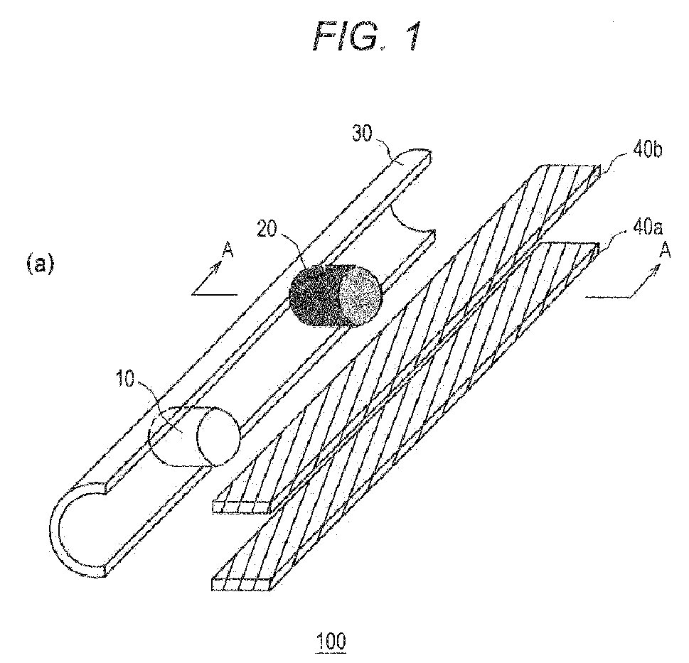
- Fig. 1 is a schematic diagram illustrating a vehicle lamp 100 according to an embodiment
- Fig. 1 (a) is a schematic perspective view
- Fig. 1 (b) is a cross-sectional view taken along the line A-A in Fig. 1 (a) .
- the vehicle lamp 100 includes a lamp 10, a sensor 20, a reflecting mirror 30, and organic EL devices 40a, 40b.
- the respective parts are housed within a housing (not illustrated) and are integrated.
- the organic EL devices 40a, 40b and the reflecting mirror 30 configure a lamp function unit and a light irradiating region according to the present invention.
- the lamp 10 is a member that irradiates a front with a light, and corresponds to a second lamp function unit according to the present invention.
- the front is a direction in which the vehicle lamp 100 is disposed to irradiate with the light.
- the vehicle lamp 100 is a front lamp, it indicates a front of a vehicle, and when the vehicle lamp 100 is a rear lamp, it indicates a rear of the vehicle.
- a light source of the lamp 10 is not limited, and may be any one of a halogen lamp, a Light Emitting Diode (LED) lamp, a High-Intensity Discharge lamp (HID) lamp, and the like.
- the lamp 10 achieves various kinds of lamp functions by being supplied with an electric power and a signal by a wiring (not illustrated) from an outside, and irradiates a front of the vehicle lamp 100 with a predetermined light.
- the vehicle lamp 100 When the vehicle lamp 100 is a front lamp, the vehicle lamp 100 may achieve various kinds of lamp functions, such as a headlamp, a turn-signal lamp, and a daytime running lamp. When the vehicle lamp 100 is a rear lamp, the vehicle lamp 100 may achieve various kinds of lamp functions, such as a stop lamp, a tail lamp, and a turn-signal lamp. While Fig. 1 illustrates the example in which only one lamp 10 is disposed, a plurality of the lamps 10 that achieve an identical function may be disposed, or the plurality of lamps 10 may be disposed to achieve different functions.
- the sensor 20 is a portion that includes sensors that measure an external environment of the vehicle lamp 100.
- Functions included in the sensor 20 include a camera that includes an imaging device, such as a Charge Coupled Device (CCD) and a Complementary MOS (CMOS), and LIDAR and the like that measure a distance by including a laser device, and they correspond the sensor function unit according to the present invention.
- the sensor 20 is coupled with the wiring from the outside of the vehicle lamp 100.
- various kinds of sensor functions operate to execute a measurement of the external environment, and its measurement result is transmitted to a control device mounted on the vehicle via the wiring.
- Fig. 1 illustrates the example in which only one sensor 20 is included, a plurality of the sensors 20 that achieves an identical function may be included or the plurality of sensors 20 may be included to achieve different functions.
- the reflecting mirror 30 is a member disposed at a rear of the lamp 10, the sensor 20, and the organic EL devices 40a, 40b, and has a reflecting surface that reflects the light.
- the reflecting mirror 30 forms a light irradiating region of the present invention.
- the lamp 10 and the sensor 20 are disposed.
- the lamp 10 and the sensor 20 are positioned within a region of the reflecting mirror 30. While in the example illustrated in Fig. 1 , a semi-cylinder shaped one is illustrated as the reflecting mirror 30, and the light irradiating region is illustrated in a rectangular shape, any shape may be employed.
- the organic EL devices 40a, 40b are members that emit predetermined lights by being supplied with the electric power by the wiring (not illustrated), and correspond to a light source unit according to the present invention. As illustrated in Fig. 1 , the organic EL devices 40a, 40b are flat plate shaped members, and are disposed in approximately parallel above and under the lamp 10 and the sensor 20 in front of the reflecting mirror 30. The lights emitted by the organic EL device 40a and the organic EL device 40b may have the same colors, or may emit mutually different colored lights.
- the organic EL devices 40a, 40b may be in curved surface shapes instead of the flat plate shapes, and may have a flexibility.
- the lights emitted from the organic EL devices 40a, 40b are irradiated on the front of the vehicle lamp 100 and are also irradiated toward the lamp 10, the sensor 20, and the reflecting mirror 30.
- the light irradiated toward the reflecting mirror 30 is reflected by the reflecting mirror 30 to be irradiated on the front of the vehicle lamp 100.
- the organic EL devices 40a, 40b and the reflecting mirror 30 configure the lamp function unit and the light irradiating region according to the present invention. Since the organic EL devices 40a, 40b and the reflecting mirror 30 configure the lamp function unit and the light irradiating region of the present invention, only the sensor 20 may be arranged within the region of the reflecting mirror 30 without arranging the lamp 10.
- the lamp 10 when the organic EL devices 40a, 40b emit the lights, the lamp 10, the sensor 20, and the reflecting mirror 30 are irradiated with the lights from the organic EL devices 40a, 40b, and the lights are reflected by respective surfaces of the lamp 10, the sensor 20, and the reflecting mirror 30. Accordingly, the sensor 20 is disposed inside the light irradiating region, and it is visually perceived as if the whole vehicle lamp 100 including the sensor 20 emits the light. This causes the sensor 20 to be visually perceived as a light emitting region from the outside even though the sensor 20 is a non-light-emitting element, thereby ensuring an improved designability. Downsizing and thinning of the vehicle lamp 100 can also be achieved. Since there is no member that obstructs the front of the lamp 10 and the sensor 20, the incidence and emission of the light is not interfered between the lamp 10 and sensor 20 and the outside, thereby ensuring proper light irradiation and external environment measurement.
- the organic EL devices 40a, 40b as the light source unit emit the lights even in a day time, and the lights are constantly reflected by the whole reflecting mirror 30, to cause the sensor 20 to be difficult to be visually perceived from the outside, thereby ensuring a further enhanced designability.
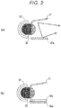
- Fig. 2 is a schematic diagram illustrating a modification of the first embodiment
- Fig. 2(a) is an example using a reflective plate 31
- Fig. 2(b) is an example using the reflective plate 31 and a transparent organic EL device 40c.
- the modification illustrated in Fig. 2(a) only the organic EL device 40a is used as the light source unit, and the reflective plate 31 is used instead of the organic EL device 40b.
- the reflective plate 31 is disposed along a longitudinal direction of the reflecting mirror 30 in the front and an upper side of the reflecting mirror 30, and is a member having a reflecting surface that reflects the light. While Figs. 2(a) and 2(b) illustrate an approximately flat plate shaped one as the reflective plate 31, the reflecting surface may be in a curved surface shape.
- the light emitted from the organic EL device 40a is irradiated on the front of the vehicle lamp 100, and is irradiated toward the lamp 10, the sensor 20, the reflecting mirror 30, and the reflective plate 31.
- the light irradiated toward the reflecting mirror 30 is reflected by the reflecting mirror 30 to be irradiated on the front of the vehicle lamp 100.
- the light irradiated toward the reflective plate 31 is reflected by the reflective plate 31 to be irradiated on the front of the vehicle lamp 100.
- the organic EL device 40a, the reflecting mirror 30, and the reflective plate 31 configure the lamp function unit and the light irradiating region according to the present invention.
- the senor 20 is visually perceived as the light emitting region from the outside even though the sensor 20 is the non-light-emitting element, thereby ensuring the improved designability. Downsizing and thinning of the vehicle lamp 100 can also be achieved.
- the organic EL device 40a and the transparent organic EL device 40c are used as the light source unit, and the reflective plate 31 is used instead of the organic EL device 40b.
- the transparent organic EL device 40c emits a predetermined light by being supplied with the electric power by the wiring (not illustrated), and is a member configured of a material that transmits a visible light.
- the transparent organic EL device 40c is disposed between the organic EL device 40a and the reflective plate 31, and the organic EL device 40a and the transparent organic EL device 40c correspond to the light source unit according to the present invention.
- the lights emitted by the organic EL device 40a and the transparent organic EL device 40c may have the same colors, or may emit mutually different colored lights.
- the light emitted from the organic EL device 40a transmits through the transparent organic EL device 40c, and the light is irradiated on the front of the vehicle lamp 100, and is irradiated toward the lamp 10, the sensor 20, the reflecting mirror 30, and the reflective plate 31.
- the light emitted from the transparent organic EL device 40c also is irradiated on the front of the vehicle lamp 100, and is irradiated toward the lamp 10, the sensor 20, the reflecting mirror 30, and the reflective plate 31.
- the light irradiated toward the reflecting mirror 30 is reflected by the reflecting mirror 30 to be irradiated on the front of the vehicle lamp 100.
- the light irradiated toward the reflective plate 31 is reflected by the reflective plate 31 to be irradiated on the front of the vehicle lamp 100. Accordingly, the organic EL device 40a, the transparent organic EL device 40c, the reflecting mirror 30, and the reflective plate 31 configure the lamp function unit and the light irradiating region according to the present invention.
- the senor 20 is visually perceived as the light emitting region from the outside even though the sensor 20 is the non-light-emitting element, thereby ensuring the improved designability. Downsizing and thinning of the vehicle lamp 100 can also be achieved.
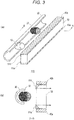
- FIG. 3 is a schematic diagram illustrating a vehicle lamp 110 according to this embodiment
- Fig. 3 (a) is a schematic perspective view
- Fig. 3 (b) is a cross-sectional view taken along the line B-B in Fig. 3 (a) .
- the vehicle lamp 110 includes the lamp 10, the sensor 20, the reflecting mirror 30, the organic EL devices 40a, 40b, a light guiding member 50, and reflective plates 51a, 51b.
- the respective parts are housed within a housing (not illustrated) and are integrated.
- the light guiding member 50 is an approximately rectangular parallelepiped shaped member configured of a material that transmits a light.
- the organic EL devices 40a, 40b are adjacently disposed on top and inferior surfaces of the light guiding member 50.
- a material that configures the light guiding member 50 is not limited, and a material that properly transmits a light, such as an acrylic resin, an epoxy resin, a polycarbonate resin, and a glass, can be used. While Fig. 3 illustrates the approximately rectangular parallelepiped shaped one as the light guiding member 50, the light guiding member 50 may be one with a curved surface in a cylindrical shape, a lens shape, and the like.
- the reflective plates 51a, 51b are disposed in regions close to the organic EL devices 40a, 40b on a back surface of the light guiding member 50.
- the reflective plates 51a, 51b are members having reflecting surfaces that scatter and reflect lights, and correspond to a scattering portion according to the present invention.
- the reflective plates 51a, 51b may be formed into separate bodies from the light guiding member 50 and be attached on the back surface of the light guiding member 50, or reflecting surfaces may be formed on the back surface of the light guiding member 50 by plating, deposition, or the like.
- Fig. 3 illustrates the example in which the reflective plates 51a, 51b are separated and disposed on the back surface of the light guiding member 50
- the reflective plates 51a, 51b may be formed across an approximately whole region of the back surface of the light guiding member 50, and only regions in front of the lamp 10 and the sensor 20 on the reflective plates 51a, 51b may be opened.
- the opening provided in front of the sensor 20 transmits an emission light from the sensor 20 to the outside and an incident light from the outside to the sensor 20, therefore, corresponds to a transmission window portion according to the present invention.
- the lights emitted from the organic EL devices 40a, 40b propagate inside the light guiding member 50, and the lights are irradiated on a front of the vehicle lamp 110, and are irradiated on the lamp 10, the sensor 20, the reflecting mirror 30, and the reflective plates 51a, 51b.
- the light irradiated toward the reflective plates 51a, 51b is scattered and reflected to be irradiated on the front of the vehicle lamp 100.
- the organic EL devices 40a, 40b as the light source unit and the reflective plates 51a, 51b as the scattering portions configure the lamp function unit and the light irradiating region according to the present invention.
- the regions where the reflective plates 51a, 51b as the scattering portions are disposed scatter the lights from the organic EL devices 40a, 40b, the regions are visually perceived as light irradiating regions from the outside.
- the region where the reflective plates 51a, 51b as the scattering portions are not disposed the incidence and emission of the light is not interfered between the lamp 10 and sensor 20 and the outside, thereby ensuring proper light irradiation and external environment measurement.
- the senor 20 is disposed inside the light irradiating region, and it is visually perceived as if the whole vehicle lamp 110 including the sensor 20 emits the light. This causes the sensor 20 to be visually perceived as the light emitting region from the outside even though the sensor 20 is the non-light-emitting element, thereby ensuring the improved designability. Downsizing and thinning of the vehicle lamp 110 can also be achieved. While the example in which the reflective plates 51a, 51b are scattering reflecting surfaces is illustrated, the reflection by the reflective plates 51a, 51b may be a specular reflection.
- Fig. 4 is a schematic diagram illustrating a modification of the second embodiment
- Fig. 4(a) is an example using scattering portions 52a, 52b
- Fig. 4(b) is an example using diffusion plates 53a, 53b.
- the scattering portions 52a, 52b in uneven shapes are formed on the back surface of the light guiding member 50 instead of the reflective plates 51a, 51b.
- this modification only the regions in front of the lamp 10 and the sensor 20 on the back surface of the light guiding member 50 are flat surfaces, and the whole other regions have the scattering portions 52a, 52b.
- the region without the scattering portions 52a, 52b transmits an emission light from the sensor 20 to the outside and an incident light from the outside to the sensor 20, therefore, corresponds to the transmission window according to the present invention.
- the lights emitted from the organic EL devices 40a, 40b propagate inside the light guiding member 50, and the lights are irradiated on the front of the vehicle lamp 110, and are irradiated on the lamp 10, the sensor 20, the reflecting mirror 30, and the scattering portions 52a, 52b.
- the light irradiated toward the scattering portions 52a, 52b is scattered and reflected to be irradiated on the front of the vehicle lamp 110.
- the organic EL devices 40a, 40b as the light source unit and the scattering portions 52a, 52b configure the lamp function unit and the light irradiating region according to the present invention.
- the diffusion plates 53a, 53b are formed on a front surface of the light guiding member 50 instead of the reflective plates 51a, 51b.
- the diffusion plates 53a, 53b are approximately plate shaped members that transmit and diffuse a light, and correspond to the scattering portions of the present invention.
- a structure of the diffusion plates 53a, 53b is not limited, and for example, a member formed by dispersing fine particles within a transparent resin can be used.
- the lights emitted from the organic EL devices 40a, 40b propagate inside the light guiding member 50, and the lights are irradiated on the front of the vehicle lamp 110, and are irradiated on the lamp 10, the sensor 20, the reflecting mirror 30, and the diffusion plates 53a, 53b.
- the light irradiated toward the diffusion plates 53a, 53b is scattered to be irradiated on the front of the vehicle lamp 110. Accordingly, the organic EL devices 40a, 40b as the light source unit and the diffusion plates 53a, 53b configure the lamp function unit and the light irradiating region according to the present invention.
- the senor 20 is visually perceived as the light emitting region from the outside even though the sensor 20 is the non-light-emitting element, thereby ensuring the improved designability. Downsizing and thinning of the vehicle lamp 110 can also be achieved.
- FIG. 5 is a schematic diagram illustrating a vehicle lamp 120 according to this embodiment
- Fig. 5 (a) is a schematic perspective view
- Fig. 5 (b) is a cross-sectional view taken along the line C-C in Fig. 5 (a) .
- the vehicle lamp 120 includes the lamp 10, the sensor 20, the reflecting mirror 30, the organic EL devices 40a, 40b, the light guiding member 50, and the reflective plates 51a, 51b.
- the respective parts are housed within a housing (not illustrated) and are integrated.
- the light guiding member 50 in this embodiment is configured of a material that transmits a light, and has scattering portions 50a that scatter the light with dispersed microparticles.
- the microparticles are not dispersed in the regions in front of the lamp 10 and the sensor 20, and transmission window portions 50b that transmit the light are configured.
- the lights emitted from the organic EL devices 40a, 40b are propagated inside the light guiding member 50 and scattered with the scattering portions 50a, and a front of the vehicle lamp 120 is irradiated with the lights. Accordingly, the organic EL devices 40a, 40b as the light source unit, and the scattering portions 50a and transmission window portions 50b configure the lamp function unit and the light irradiating region according to the present invention.
- the regions where the scattering portions 50a and the transmission window portions 50b are disposed are visually perceived as light irradiating regions from the outside since they scatter the lights from the organic EL devices 40a, 40b. In the regions where the scattering portions 50a and the transmission window portions 50b are not disposed, the incidence and emission of the light is not interfered between the lamp 10 and sensor 20 and the outside, thereby ensuring proper light irradiation and external environment measurement.
- the senor 20 is disposed inside the light irradiating region, and it is visually perceived as if the whole vehicle lamp 120 including the sensor 20 emits the light. This causes the sensor 20 to be visually perceived as the light emitting region from the outside even though the sensor 20 is the non-light-emitting element, thereby ensuring the improved designability. Downsizing and thinning of the vehicle lamp 120 can also be achieved.
- FIG. 6 is a schematic diagram illustrating a vehicle lamp 130 according to this embodiment.
- the vehicle lamp 130 includes the lamp 10, the sensor 20, the reflecting mirror 30, a plurality of LEDs 41, and the light guiding member 50.
- the respective parts are housed within a housing (not illustrated) and are integrated.
- the light guiding member 50 of this embodiment is also configured of a material that transmits a light, and has the scattering portions 50a that scatter the light with the dispersed microparticles. In the light guiding member 50, the microparticles are not dispersed in the regions in front of the lamp 10 and the sensor 20, and the transmission window portions 50b that transmit the light are configured.
- the LEDs 41 are members that emit predetermined lights by being supplied with the electric power by the wiring (not illustrated), and correspond to the light source unit according to the present invention. As illustrated in Fig. 6 , the LEDs 41 are disposed to oppose side surfaces of the light guiding member 50, and cause the lights to enter the inside from the side surfaces of the light guiding member 50. The lights emitted by the plurality of LEDs 41 may have the same colors, or may emit mutually different colored lights.
- the lights emitted from the LEDs 41 enter the light guiding member 50 from the side surfaces of the light guiding member 50, propagate inside the light guiding member 50, and are scattered in the scattering portions 50a. A front of the vehicle lamp 130 is irradiated by the lights. Accordingly, the LEDs 41 as the light source unit and the scattering portions 50a and transmission window portions 50b configure the lamp function unit and the light irradiating region according to the present invention.
- the regions where the scattering portions 50a and the transmission window portions 50b are disposed scatter the lights from the organic EL devices 40a, 40b, the regions are visually perceived as light irradiation regions from the outside.
- the regions where the scattering portions 50a and the transmission window portions 50b are not disposed the incidence and emission of the light is not interfered between the lamp 10 and sensor 20 and the outside, thereby ensuring proper light irradiation and external environment measurement.
- This causes the sensor 20 to be visually perceived as the light emitting region from the outside even though the sensor 20 is the non-light-emitting element, thereby ensuring the improved designability. Downsizing and thinning of the vehicle lamp 130 can also be achieved.
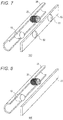
- FIG. 7 is a schematic diagram illustrating a vehicle lamp 140 according to this embodiment.
- the vehicle lamp 140 includes the lamp 10, the sensor 20, the reflecting mirror 30, and an organic EL device 60.
- the respective parts are housed within a housing (not illustrated) and are integrated.
- the organic EL device 60 is disposed so as to cover the reflecting mirror 30 in front of the lamp 10, the sensor 20, and the reflecting mirror 30.
- openings 61, 62 are formed in front of the sensor 20 and the lamp 10, respectively.
- the light emitted from the organic EL device 60 is irradiated on a front of the vehicle lamp 140. Accordingly, in this embodiment, the whole organic EL device 60 is the light irradiating region.
- the openings 61, 62 correspond to the transmission window portions.
- the organic EL device 60 is visually perceived as the light irradiating region. With the openings 61, 62, the incidence and emission of the light is not interfered between the lamp 10 and sensor 20 and the outside, thereby ensuring proper light irradiation and external environment measurement. This causes the sensor 20 to be visually perceived as the light emitting region from the outside even though the sensor 20 is the non-light-emitting element, thereby ensuring the improved designability. Downsizing and thinning of the vehicle lamp 140 can also be achieved.
- Fig. 8 is a schematic diagram illustrating a vehicle lamp 150 according to this embodiment.
- the vehicle lamp 140 includes the lamp 10, the sensor 20, the reflecting mirror 30, and a transparent organic EL device 70.
- the respective parts are housed within a housing (not illustrated) and are integrated.
- the transparent organic EL device 70 itself emits a light, and a front of the vehicle lamp 150 is irradiated with the light. Accordingly, in this embodiment, the whole transparent organic EL device 70 is the light irradiating region. Since the transparent organic EL device 70 is configured of a material that transmits a light, the incidence and emission of the light is not interfered between the lamp 10 and sensor 20 and the outside, thereby ensuring proper light irradiation and external environment measurement. This causes the sensor 20 to be visually perceived as the light emitting region from the outside even though the sensor 20 is the non-light-emitting element, thereby ensuring the improved designability. Downsizing and thinning of the vehicle lamp 150 can also be achieved.
Landscapes
- Engineering & Computer Science (AREA)
- General Engineering & Computer Science (AREA)
- Physics & Mathematics (AREA)
- Microelectronics & Electronic Packaging (AREA)
- Optics & Photonics (AREA)
- Mechanical Engineering (AREA)
- Non-Portable Lighting Devices Or Systems Thereof (AREA)
- Lighting Device Outwards From Vehicle And Optical Signal (AREA)
- Planar Illumination Modules (AREA)
- Arrangement Of Elements, Cooling, Sealing, Or The Like Of Lighting Devices (AREA)
Abstract
Description
- The present invention relates to a vehicle lamp, in particular, relates to a vehicle lamp having a sensor function.
- As a vehicle lamp in recent years, there has been proposed a vehicle lamp in which various functions, such as a headlamp, a daytime running lamp, and a turn signal, are integrated, and a size of a whole lamp tends to be increased to a large-size. There has also been a desire to integrate sensors, such as a camera and a Light Detection and Ranging (LIDAR), into a vehicle lamp, in order to obtain various kinds of information to assist in driving a vehicle.
- PATENT LITERATURE 1 discloses a vehicle lamp in which various kinds of lamps and sensors are integrated. PATENT LITERATURE 1 houses a plurality of lamp units and cameras within a housing, and an extension is provided between the lamp unit and the camera to separate and dispose the lamp unit and the camera from one another.
- PATENT LITERATURE 1:
JP-A-2013-159200 - In order to improve fuel efficiency and aerodynamic characteristics of a vehicle, it is preferred to downsize, thin, and narrow a vehicle lamp. However, since the vehicle lamp in PATENT LITERATURE 1 disposes the plurality of lamp units and cameras in parallel, a lamp size is further increased, thereby making it difficult to achieve downsizing, thinning, and narrowing. When the sensors are disposed inside the vehicle lamp, a region where the sensors are disposed is visually perceived from an outside as a non-light-emitting region, thereby causing a problem of a poor designability.
- Therefore, the present invention has been made in view of the above-described conventional problems, and it is an object of the present invention to provide a vehicle lamp that ensures achieving downsizing while integrating sensors, and improving a designability.
- To solve the above-described problem, a vehicle lamp according to the present invention includes a lamp function unit and a sensor function unit, wherein the lamp function unit has a light irradiating region, and the sensor function unit is arranged within the light irradiating region in a front view.
- With such a vehicle lamp according to the present invention, since the sensor function unit is disposed in the light irradiating region of the lamp function unit, the vehicle lamp can be downsized, and since the sensor function unit is difficult to be visually perceived when the lamp function unit emits a light, a designability also improves.
- An aspect according to the present invention, in front of the sensor function unit, a transmission window portion that transmits a light is disposed in the light irradiating region.
- Another aspect according to the present invention, the light irradiating region is configured of an organic EL device.
- Still another aspect according to the present invention, the light irradiating region is configured of a light source unit and a reflecting mirror that reflects a light from the light source unit.
- Still another aspect according to the present invention, the light irradiating region is configured of a light source unit and a light guiding member, and a scattering portion that scatters a light from the light source unit is formed on the light guiding member.
- Still another aspect according to the present invention, a second lamp function unit, wherein the second lamp function unit is arranged within the light irradiating region in a front view.
- The present invention ensures providing a vehicle lamp that ensures achieving downsizing while integrating sensors, and improving a designability.
-
-
Fig. 1 is a schematic diagram illustrating avehicle lamp 100 according to a first embodiment,Fig. 1(a) is a schematic perspective view, andFig. 1(b) is a cross-sectional view taken along the line A-A inFig. 1(a) . -
Fig. 2 is a schematic diagram illustrating a modification of the first embodiment,Fig. 2(a) is an example using areflective plate 31, andFig. 2(b) is an example using thereflective plate 31 and a transparentorganic EL device 40c. -
Fig. 3 is a schematic diagram illustrating avehicle lamp 110 according to a second embodiment,Fig. 3(a) is a schematic perspective view, andFig. 3(b) is a cross-sectional view taken along the line B-B inFig. 3(a) . -
Fig. 4 is a schematic diagram illustrating a modification of the second embodiment,Fig. 4(a) is an example using scatteringportions Fig. 4(b) is an example usingdiffusion plates -
Fig. 5 is a schematic diagram illustrating avehicle lamp 120 according to a third embodiment,Fig. 5(a) is a schematic perspective view, andFig. 5(b) is a cross-sectional view taken along the line C-C inFig. 5(a) . -
Fig. 6 is a schematic perspective view illustrating avehicle lamp 130 according to a fourth embodiment. -
Fig. 7 is a schematic perspective view illustrating avehicle lamp 140 according to a fifth embodiment. -
Fig. 8 is a schematic perspective view illustrating avehicle lamp 150 according to a sixth embodiment. - The following describes embodiments of the present invention in details with reference to the drawings. Identical or equivalent components, members, and treatments illustrated in each drawing are attached by identical reference numerals, and repeated explanation is appropriately omitted.
Fig. 1 is a schematic diagram illustrating avehicle lamp 100 according to an embodiment,Fig. 1 (a) is a schematic perspective view, andFig. 1 (b) is a cross-sectional view taken along the line A-A inFig. 1 (a) . Thevehicle lamp 100 includes alamp 10, asensor 20, a reflectingmirror 30, andorganic EL devices organic EL devices mirror 30 configure a lamp function unit and a light irradiating region according to the present invention. - The
lamp 10 is a member that irradiates a front with a light, and corresponds to a second lamp function unit according to the present invention. Here, the front is a direction in which thevehicle lamp 100 is disposed to irradiate with the light. When thevehicle lamp 100 is a front lamp, it indicates a front of a vehicle, and when thevehicle lamp 100 is a rear lamp, it indicates a rear of the vehicle. A light source of thelamp 10 is not limited, and may be any one of a halogen lamp, a Light Emitting Diode (LED) lamp, a High-Intensity Discharge lamp (HID) lamp, and the like. Thelamp 10 achieves various kinds of lamp functions by being supplied with an electric power and a signal by a wiring (not illustrated) from an outside, and irradiates a front of thevehicle lamp 100 with a predetermined light. - When the
vehicle lamp 100 is a front lamp, thevehicle lamp 100 may achieve various kinds of lamp functions, such as a headlamp, a turn-signal lamp, and a daytime running lamp. When thevehicle lamp 100 is a rear lamp, thevehicle lamp 100 may achieve various kinds of lamp functions, such as a stop lamp, a tail lamp, and a turn-signal lamp. WhileFig. 1 illustrates the example in which only onelamp 10 is disposed, a plurality of thelamps 10 that achieve an identical function may be disposed, or the plurality oflamps 10 may be disposed to achieve different functions. - The
sensor 20 is a portion that includes sensors that measure an external environment of thevehicle lamp 100. Functions included in thesensor 20 include a camera that includes an imaging device, such as a Charge Coupled Device (CCD) and a Complementary MOS (CMOS), and LIDAR and the like that measure a distance by including a laser device, and they correspond the sensor function unit according to the present invention. - The
sensor 20 is coupled with the wiring from the outside of thevehicle lamp 100. When the electric power is supplied, various kinds of sensor functions operate to execute a measurement of the external environment, and its measurement result is transmitted to a control device mounted on the vehicle via the wiring. WhileFig. 1 illustrates the example in which only onesensor 20 is included, a plurality of thesensors 20 that achieves an identical function may be included or the plurality ofsensors 20 may be included to achieve different functions. - The reflecting
mirror 30 is a member disposed at a rear of thelamp 10, thesensor 20, and theorganic EL devices mirror 30 forms a light irradiating region of the present invention. In the reflecting surface of the reflectingmirror 30, thelamp 10 and thesensor 20 are disposed. In a front view from the front of thevehicle lamp 100, thelamp 10 and thesensor 20 are positioned within a region of the reflectingmirror 30. While in the example illustrated inFig. 1 , a semi-cylinder shaped one is illustrated as the reflectingmirror 30, and the light irradiating region is illustrated in a rectangular shape, any shape may be employed. - The
organic EL devices Fig. 1 , theorganic EL devices lamp 10 and thesensor 20 in front of the reflectingmirror 30. The lights emitted by theorganic EL device 40a and theorganic EL device 40b may have the same colors, or may emit mutually different colored lights. Theorganic EL devices - The lights emitted from the
organic EL devices vehicle lamp 100 and are also irradiated toward thelamp 10, thesensor 20, and the reflectingmirror 30. The light irradiated toward the reflectingmirror 30 is reflected by the reflectingmirror 30 to be irradiated on the front of thevehicle lamp 100. Accordingly, theorganic EL devices mirror 30 configure the lamp function unit and the light irradiating region according to the present invention. Since theorganic EL devices mirror 30 configure the lamp function unit and the light irradiating region of the present invention, only thesensor 20 may be arranged within the region of the reflectingmirror 30 without arranging thelamp 10. - In the
vehicle lamp 100 according to this embodiment, when theorganic EL devices lamp 10, thesensor 20, and the reflectingmirror 30 are irradiated with the lights from theorganic EL devices lamp 10, thesensor 20, and the reflectingmirror 30. Accordingly, thesensor 20 is disposed inside the light irradiating region, and it is visually perceived as if thewhole vehicle lamp 100 including thesensor 20 emits the light. This causes thesensor 20 to be visually perceived as a light emitting region from the outside even though thesensor 20 is a non-light-emitting element, thereby ensuring an improved designability. Downsizing and thinning of thevehicle lamp 100 can also be achieved. Since there is no member that obstructs the front of thelamp 10 and thesensor 20, the incidence and emission of the light is not interfered between thelamp 10 andsensor 20 and the outside, thereby ensuring proper light irradiation and external environment measurement. - In particular, when the
vehicle lamp 100 is used as the daytime running lamp or the tail lamp, theorganic EL devices whole reflecting mirror 30, to cause thesensor 20 to be difficult to be visually perceived from the outside, thereby ensuring a further enhanced designability. -
Fig. 2 is a schematic diagram illustrating a modification of the first embodiment,Fig. 2(a) is an example using areflective plate 31, andFig. 2(b) is an example using thereflective plate 31 and a transparentorganic EL device 40c. In the modification illustrated inFig. 2(a) , only theorganic EL device 40a is used as the light source unit, and thereflective plate 31 is used instead of theorganic EL device 40b. - The
reflective plate 31 is disposed along a longitudinal direction of the reflectingmirror 30 in the front and an upper side of the reflectingmirror 30, and is a member having a reflecting surface that reflects the light. WhileFigs. 2(a) and 2(b) illustrate an approximately flat plate shaped one as thereflective plate 31, the reflecting surface may be in a curved surface shape. - In this modification, the light emitted from the
organic EL device 40a is irradiated on the front of thevehicle lamp 100, and is irradiated toward thelamp 10, thesensor 20, the reflectingmirror 30, and thereflective plate 31. The light irradiated toward the reflectingmirror 30 is reflected by the reflectingmirror 30 to be irradiated on the front of thevehicle lamp 100. The light irradiated toward thereflective plate 31 is reflected by thereflective plate 31 to be irradiated on the front of thevehicle lamp 100. Accordingly, theorganic EL device 40a, the reflectingmirror 30, and thereflective plate 31 configure the lamp function unit and the light irradiating region according to the present invention. - Also in this modification, the
sensor 20 is visually perceived as the light emitting region from the outside even though thesensor 20 is the non-light-emitting element, thereby ensuring the improved designability. Downsizing and thinning of thevehicle lamp 100 can also be achieved. - In the modification illustrated in
Fig. 2 (b) , theorganic EL device 40a and the transparentorganic EL device 40c are used as the light source unit, and thereflective plate 31 is used instead of theorganic EL device 40b. The transparentorganic EL device 40c emits a predetermined light by being supplied with the electric power by the wiring (not illustrated), and is a member configured of a material that transmits a visible light. As illustrated inFig. 2 (b) , the transparentorganic EL device 40c is disposed between theorganic EL device 40a and thereflective plate 31, and theorganic EL device 40a and the transparentorganic EL device 40c correspond to the light source unit according to the present invention. The lights emitted by theorganic EL device 40a and the transparentorganic EL device 40c may have the same colors, or may emit mutually different colored lights. - In this modification, the light emitted from the
organic EL device 40a transmits through the transparentorganic EL device 40c, and the light is irradiated on the front of thevehicle lamp 100, and is irradiated toward thelamp 10, thesensor 20, the reflectingmirror 30, and thereflective plate 31. Similarly, the light emitted from the transparentorganic EL device 40c also is irradiated on the front of thevehicle lamp 100, and is irradiated toward thelamp 10, thesensor 20, the reflectingmirror 30, and thereflective plate 31. The light irradiated toward the reflectingmirror 30 is reflected by the reflectingmirror 30 to be irradiated on the front of thevehicle lamp 100. The light irradiated toward thereflective plate 31 is reflected by thereflective plate 31 to be irradiated on the front of thevehicle lamp 100. Accordingly, theorganic EL device 40a, the transparentorganic EL device 40c, the reflectingmirror 30, and thereflective plate 31 configure the lamp function unit and the light irradiating region according to the present invention. - Also in this modification, the
sensor 20 is visually perceived as the light emitting region from the outside even though thesensor 20 is the non-light-emitting element, thereby ensuring the improved designability. Downsizing and thinning of thevehicle lamp 100 can also be achieved. - Next, a second embodiment of the present invention will be described by referring to
Fig. 3 . Duplicate description of components corresponding to those of the first embodiment is omitted.Fig. 3 is a schematic diagram illustrating avehicle lamp 110 according to this embodiment,Fig. 3 (a) is a schematic perspective view, andFig. 3 (b) is a cross-sectional view taken along the line B-B inFig. 3 (a) . Thevehicle lamp 110 includes thelamp 10, thesensor 20, the reflectingmirror 30, theorganic EL devices light guiding member 50, andreflective plates - The
light guiding member 50 is an approximately rectangular parallelepiped shaped member configured of a material that transmits a light. Theorganic EL devices light guiding member 50. A material that configures thelight guiding member 50 is not limited, and a material that properly transmits a light, such as an acrylic resin, an epoxy resin, a polycarbonate resin, and a glass, can be used. WhileFig. 3 illustrates the approximately rectangular parallelepiped shaped one as thelight guiding member 50, thelight guiding member 50 may be one with a curved surface in a cylindrical shape, a lens shape, and the like. - The
reflective plates organic EL devices light guiding member 50. Thereflective plates reflective plates light guiding member 50 and be attached on the back surface of thelight guiding member 50, or reflecting surfaces may be formed on the back surface of thelight guiding member 50 by plating, deposition, or the like. - While
Fig. 3 illustrates the example in which thereflective plates light guiding member 50, thereflective plates light guiding member 50, and only regions in front of thelamp 10 and thesensor 20 on thereflective plates sensor 20 transmits an emission light from thesensor 20 to the outside and an incident light from the outside to thesensor 20, therefore, corresponds to a transmission window portion according to the present invention. - The lights emitted from the
organic EL devices light guiding member 50, and the lights are irradiated on a front of thevehicle lamp 110, and are irradiated on thelamp 10, thesensor 20, the reflectingmirror 30, and thereflective plates reflective plates vehicle lamp 100. Accordingly, theorganic EL devices reflective plates - Since the regions where the
reflective plates organic EL devices reflective plates lamp 10 andsensor 20 and the outside, thereby ensuring proper light irradiation and external environment measurement. - Even in this embodiment, the
sensor 20 is disposed inside the light irradiating region, and it is visually perceived as if thewhole vehicle lamp 110 including thesensor 20 emits the light. This causes thesensor 20 to be visually perceived as the light emitting region from the outside even though thesensor 20 is the non-light-emitting element, thereby ensuring the improved designability. Downsizing and thinning of thevehicle lamp 110 can also be achieved. While the example in which thereflective plates reflective plates -
Fig. 4 is a schematic diagram illustrating a modification of the second embodiment,Fig. 4(a) is an example usingscattering portions Fig. 4(b) is an example usingdiffusion plates Fig. 4(a) , the scatteringportions light guiding member 50 instead of thereflective plates lamp 10 and thesensor 20 on the back surface of thelight guiding member 50 are flat surfaces, and the whole other regions have thescattering portions light guiding member 50, the region without the scatteringportions sensor 20 to the outside and an incident light from the outside to thesensor 20, therefore, corresponds to the transmission window according to the present invention. - Even in this modification, the lights emitted from the
organic EL devices light guiding member 50, and the lights are irradiated on the front of thevehicle lamp 110, and are irradiated on thelamp 10, thesensor 20, the reflectingmirror 30, and thescattering portions portions vehicle lamp 110. Accordingly, theorganic EL devices scattering portions - In the modification illustrated in
Fig. 4 (b) , thediffusion plates light guiding member 50 instead of thereflective plates diffusion plates diffusion plates - Even in this modification, the lights emitted from the
organic EL devices light guiding member 50, and the lights are irradiated on the front of thevehicle lamp 110, and are irradiated on thelamp 10, thesensor 20, the reflectingmirror 30, and thediffusion plates diffusion plates vehicle lamp 110. Accordingly, theorganic EL devices diffusion plates - Even in the modification illustrated in
Figs. 4(a) and 4(b) , thesensor 20 is visually perceived as the light emitting region from the outside even though thesensor 20 is the non-light-emitting element, thereby ensuring the improved designability. Downsizing and thinning of thevehicle lamp 110 can also be achieved. - Next, a third embodiment of the present invention will be described by referring to
Fig. 5 . Duplicate description of components corresponding to those of the first embodiment is omitted.Fig. 5 is a schematic diagram illustrating avehicle lamp 120 according to this embodiment,Fig. 5 (a) is a schematic perspective view, andFig. 5 (b) is a cross-sectional view taken along the line C-C inFig. 5 (a) . Thevehicle lamp 120 includes thelamp 10, thesensor 20, the reflectingmirror 30, theorganic EL devices light guiding member 50, and thereflective plates - The
light guiding member 50 in this embodiment is configured of a material that transmits a light, and has scatteringportions 50a that scatter the light with dispersed microparticles. In thelight guiding member 50, the microparticles are not dispersed in the regions in front of thelamp 10 and thesensor 20, andtransmission window portions 50b that transmit the light are configured. - The lights emitted from the
organic EL devices light guiding member 50 and scattered with the scatteringportions 50a, and a front of thevehicle lamp 120 is irradiated with the lights. Accordingly, theorganic EL devices scattering portions 50a andtransmission window portions 50b configure the lamp function unit and the light irradiating region according to the present invention. - The regions where the
scattering portions 50a and thetransmission window portions 50b are disposed are visually perceived as light irradiating regions from the outside since they scatter the lights from theorganic EL devices scattering portions 50a and thetransmission window portions 50b are not disposed, the incidence and emission of the light is not interfered between thelamp 10 andsensor 20 and the outside, thereby ensuring proper light irradiation and external environment measurement. - Even in this embodiment, the
sensor 20 is disposed inside the light irradiating region, and it is visually perceived as if thewhole vehicle lamp 120 including thesensor 20 emits the light. This causes thesensor 20 to be visually perceived as the light emitting region from the outside even though thesensor 20 is the non-light-emitting element, thereby ensuring the improved designability. Downsizing and thinning of thevehicle lamp 120 can also be achieved. - Next, a fourth embodiment of the present invention will be described by referring to
Fig. 6 . Duplicate description of components corresponding to those of the first embodiment is omitted.Fig. 6 is a schematic diagram illustrating avehicle lamp 130 according to this embodiment. Thevehicle lamp 130 includes thelamp 10, thesensor 20, the reflectingmirror 30, a plurality ofLEDs 41, and thelight guiding member 50. The respective parts are housed within a housing (not illustrated) and are integrated. Thelight guiding member 50 of this embodiment is also configured of a material that transmits a light, and has thescattering portions 50a that scatter the light with the dispersed microparticles. In thelight guiding member 50, the microparticles are not dispersed in the regions in front of thelamp 10 and thesensor 20, and thetransmission window portions 50b that transmit the light are configured. - The
LEDs 41 are members that emit predetermined lights by being supplied with the electric power by the wiring (not illustrated), and correspond to the light source unit according to the present invention. As illustrated inFig. 6 , theLEDs 41 are disposed to oppose side surfaces of thelight guiding member 50, and cause the lights to enter the inside from the side surfaces of thelight guiding member 50. The lights emitted by the plurality ofLEDs 41 may have the same colors, or may emit mutually different colored lights. - The lights emitted from the
LEDs 41 enter thelight guiding member 50 from the side surfaces of thelight guiding member 50, propagate inside thelight guiding member 50, and are scattered in thescattering portions 50a. A front of thevehicle lamp 130 is irradiated by the lights. Accordingly, theLEDs 41 as the light source unit and thescattering portions 50a andtransmission window portions 50b configure the lamp function unit and the light irradiating region according to the present invention. - Even in this embodiment, since the regions where the
scattering portions 50a and thetransmission window portions 50b are disposed scatter the lights from theorganic EL devices scattering portions 50a and thetransmission window portions 50b are not disposed, the incidence and emission of the light is not interfered between thelamp 10 andsensor 20 and the outside, thereby ensuring proper light irradiation and external environment measurement. This causes thesensor 20 to be visually perceived as the light emitting region from the outside even though thesensor 20 is the non-light-emitting element, thereby ensuring the improved designability. Downsizing and thinning of thevehicle lamp 130 can also be achieved. - Next, a fifth embodiment of the present invention will be described by referring to
Fig. 7 . Duplicate description of components corresponding to those of the first embodiment is omitted.Fig. 7 is a schematic diagram illustrating avehicle lamp 140 according to this embodiment. Thevehicle lamp 140 includes thelamp 10, thesensor 20, the reflectingmirror 30, and anorganic EL device 60. The respective parts are housed within a housing (not illustrated) and are integrated. - As illustrated in
Fig. 7 , theorganic EL device 60 is disposed so as to cover the reflectingmirror 30 in front of thelamp 10, thesensor 20, and the reflectingmirror 30. On theorganic EL device 60,openings sensor 20 and thelamp 10, respectively. The light emitted from theorganic EL device 60 is irradiated on a front of thevehicle lamp 140. Accordingly, in this embodiment, the wholeorganic EL device 60 is the light irradiating region. Theopenings - In this embodiment, the
organic EL device 60 is visually perceived as the light irradiating region. With theopenings lamp 10 andsensor 20 and the outside, thereby ensuring proper light irradiation and external environment measurement. This causes thesensor 20 to be visually perceived as the light emitting region from the outside even though thesensor 20 is the non-light-emitting element, thereby ensuring the improved designability. Downsizing and thinning of thevehicle lamp 140 can also be achieved. - Next, a sixth embodiment of the present invention will be described by referring to
Fig. 8 . Duplicate description of components corresponding to those of the first embodiment is omitted.Fig. 8 is a schematic diagram illustrating avehicle lamp 150 according to this embodiment. Thevehicle lamp 140 includes thelamp 10, thesensor 20, the reflectingmirror 30, and a transparentorganic EL device 70. The respective parts are housed within a housing (not illustrated) and are integrated. - The transparent
organic EL device 70 itself emits a light, and a front of thevehicle lamp 150 is irradiated with the light. Accordingly, in this embodiment, the whole transparentorganic EL device 70 is the light irradiating region. Since the transparentorganic EL device 70 is configured of a material that transmits a light, the incidence and emission of the light is not interfered between thelamp 10 andsensor 20 and the outside, thereby ensuring proper light irradiation and external environment measurement. This causes thesensor 20 to be visually perceived as the light emitting region from the outside even though thesensor 20 is the non-light-emitting element, thereby ensuring the improved designability. Downsizing and thinning of thevehicle lamp 150 can also be achieved. - The present invention is not limited to each of the above-described embodiments. Various kinds of changes are allowed within a scope of the claims, and embodiments obtained by appropriately combining each of the disclosed technical means with different embodiments are also included in the technical scope of the present invention.
- This application claims priority from Japanese Patent Application No.
2017-101471 - The above description of a specific embodiment of the present invention is disclosed as illustrative. This does not intend to be exhaustive or limit the present invention to the described embodiments as they are. Many modifications and variations will be apparent to one of ordinary skill in the art in light of the above teachings.
-
- 100, 110, 120, 130, 140, 150:
- Vehicle lamp
- 10:
- Lamp
- 20:
- Sensor
- 30:
- Reflecting mirror
- 31:
- Reflective plate
- 40a, 40b, 40c, 60:
- Organic EL device
- 40c, 70:
- Transparent organic EL device
- 41:
- LED
- 50:
- Light guiding member
- 50a, 52a, 52b:
- Scattering portion
- 50b:
- Transmit window portion
- 51a, 51b:
- Reflective plate
- 53a, 53b:
- Diffusion plate
- 61, 62:
- Opening
Claims (6)
- A vehicle lamp comprising:a lamp function unit and a sensor function unit, whereinthe lamp function unit has a light irradiating region, andthe sensor function unit is arranged within the light irradiating region in a front view.
- The vehicle lamp according to claim 1, wherein
in front of the sensor function unit, a transmission window portion that transmits a light is disposed in the light irradiating region. - The vehicle lamp according to claim 1 or 2, wherein
the light irradiating region is configured of an organic EL device. - The vehicle lamp according to claim 1 or 2, wherein
the light irradiating region is configured of a light source unit and a reflecting mirror that reflects a light from the light source unit. - The vehicle lamp according to claim 1 or 2, wherein
the light irradiating region is configured of a light source unit and a light guiding member, and a scattering portion that scatters a light from the light source unit is formed on the light guiding member. - The vehicle lamp according to any one of claims 1 to 5, comprising
a second lamp function unit, wherein
the second lamp function unit is arranged within the light irradiating region in a front view.
Applications Claiming Priority (2)
| Application Number | Priority Date | Filing Date | Title |
|---|---|---|---|
| JP2017101471A JP6938219B2 (en) | 2017-05-23 | 2017-05-23 | Vehicle lighting |
| PCT/JP2018/018682 WO2018216547A1 (en) | 2017-05-23 | 2018-05-15 | Vehicle lamp |
Publications (2)
| Publication Number | Publication Date |
|---|---|
| EP3633261A1 true EP3633261A1 (en) | 2020-04-08 |
| EP3633261A4 EP3633261A4 (en) | 2021-04-07 |
Family
ID=64395499
Family Applications (1)
| Application Number | Title | Priority Date | Filing Date |
|---|---|---|---|
| EP18806733.4A Withdrawn EP3633261A4 (en) | 2017-05-23 | 2018-05-15 | VEHICLE HEADLIGHT |
Country Status (5)
| Country | Link |
|---|---|
| US (1) | US10823354B2 (en) |
| EP (1) | EP3633261A4 (en) |
| JP (1) | JP6938219B2 (en) |
| CN (1) | CN110678690B (en) |
| WO (1) | WO2018216547A1 (en) |
Families Citing this family (2)
| Publication number | Priority date | Publication date | Assignee | Title |
|---|---|---|---|---|
| JP7158279B2 (en) * | 2018-12-28 | 2022-10-21 | 株式会社小糸製作所 | beacon system |
| JP2023134077A (en) * | 2022-03-14 | 2023-09-27 | スタンレー電気株式会社 | Vehicle lights |
Family Cites Families (19)
| Publication number | Priority date | Publication date | Assignee | Title |
|---|---|---|---|---|
| JP3544010B2 (en) | 1994-10-25 | 2004-07-21 | 本田技研工業株式会社 | Vehicle lighting |
| JP4212153B2 (en) * | 1998-07-22 | 2009-01-21 | 日東樹脂工業株式会社 | Combined light source device |
| FR2809162B1 (en) * | 2000-05-18 | 2002-07-26 | Sagem | ILLUMINATION SYSTEM WITH FAILURE DETECTION |
| US6821003B2 (en) * | 2002-07-16 | 2004-11-23 | Visteon Global Technologies, Inc. | Vehicle lamp and vehicle illumination and data transmission system incorporating same |
| DE102010049164A1 (en) * | 2010-10-24 | 2012-04-26 | Stefan Etter | Polystyrene cup for storing e.g. beer, is closed with stable aluminum lid or stable plastic lid, where cup is filled with alcoholic contents i.e. beer, or non-alcoholic contents e.g. mineral water and juice |
| CZ306862B6 (en) * | 2011-06-23 | 2017-08-16 | Varroc Lighting Systems, s.r.o. | A headlight signal lamp with a hidden light source |
| JP2013159200A (en) | 2012-02-03 | 2013-08-19 | Stanley Electric Co Ltd | Vehicle periphery monitoring apparatus |
| DE102012004916A1 (en) * | 2012-03-09 | 2012-09-20 | Daimler Ag | Lighting device for use as indicator, brake lights, headlights, tail lights or daytime running lights in motor vehicle, has light source and light sensor arranged on common carrier |
| US20140247349A1 (en) * | 2013-03-04 | 2014-09-04 | GM Global Technology Operations LLC | Integrated lighting, camera and sensor unit |
| WO2014141597A1 (en) * | 2013-03-14 | 2014-09-18 | 株式会社小糸製作所 | Vehicle lamp fitting |
| JP6161193B2 (en) * | 2013-03-21 | 2017-07-12 | 株式会社Subaru | Vehicle lamp device |
| JP2015080963A (en) * | 2013-10-21 | 2015-04-27 | 株式会社小糸製作所 | Vehicle sign light |
| WO2015072133A1 (en) * | 2013-11-15 | 2015-05-21 | パナソニックIpマネジメント株式会社 | Lamp unit |
| JP2017007356A (en) * | 2013-11-15 | 2017-01-12 | パナソニックIpマネジメント株式会社 | Lamp unit |
| JP6305167B2 (en) * | 2014-04-04 | 2018-04-04 | 三菱電機株式会社 | Automotive headlamp |
| JP2015215964A (en) * | 2014-05-08 | 2015-12-03 | 市光工業株式会社 | Vehicle lighting |
| FR3031792B1 (en) * | 2015-01-15 | 2018-08-10 | Valeo Iluminacion | METHOD FOR CONTROLLING A VEHICLE REAR LIGHT |
| JP2017101471A (en) | 2015-12-02 | 2017-06-08 | Ykk Ap株式会社 | Fitting for renovation |
| CN105546450B (en) * | 2016-01-19 | 2025-04-11 | 王振环 | Automobile headlight with variable color temperature and adjustable focal length |
-
2017
- 2017-05-23 JP JP2017101471A patent/JP6938219B2/en active Active
-
2018
- 2018-05-15 CN CN201880034198.1A patent/CN110678690B/en active Active
- 2018-05-15 EP EP18806733.4A patent/EP3633261A4/en not_active Withdrawn
- 2018-05-15 WO PCT/JP2018/018682 patent/WO2018216547A1/en not_active Ceased
- 2018-05-15 US US16/614,004 patent/US10823354B2/en active Active
Also Published As
| Publication number | Publication date |
|---|---|
| WO2018216547A1 (en) | 2018-11-29 |
| JP2018198121A (en) | 2018-12-13 |
| JP6938219B2 (en) | 2021-09-22 |
| US20200072429A1 (en) | 2020-03-05 |
| US10823354B2 (en) | 2020-11-03 |
| CN110678690A (en) | 2020-01-10 |
| EP3633261A4 (en) | 2021-04-07 |
| CN110678690B (en) | 2023-07-25 |
Similar Documents
| Publication | Publication Date | Title |
|---|---|---|
| US20190170317A1 (en) | Light device, especially signal lamp, for motor vehicles | |
| US11624490B2 (en) | Lighting apparatus for vehicles | |
| EP2557357A2 (en) | Vehicle lighting device | |
| CN102297374A (en) | Vehicle light fitting unit | |
| CN104864336B (en) | Lamps apparatus for vehicle | |
| CN109844403B (en) | Lamp assembly for vehicle | |
| JP2005346970A5 (en) | ||
| JP2008135227A5 (en) | ||
| CN105392672A (en) | Vehicle light for lighting the interior of a vehicle | |
| CN106133437A (en) | Light guide parts for vehicles, lamps for vehicles | |
| US10823354B2 (en) | Vehicle lamp | |
| CN110307519A (en) | The framework of motor vehicles including body component and the illumination and/or signal device that are mounted in the body component | |
| CN102725586B (en) | Lighting module | |
| JP6466440B2 (en) | Lighting system with integrated LEDs, especially for automotive lighting components | |
| CN105473383B (en) | Lighting systems for motor vehicle lighting components with light-emitting elements offset from light sources | |
| JP7218039B2 (en) | Light guide member for vehicle, lamp for vehicle | |
| RU2013146108A (en) | LIGHTING DEVICE, LAMP AND LIGHT | |
| CN112739951B (en) | Optical modules, especially for use in lighting devices for motor vehicles | |
| CN108884693B (en) | Motor vehicle lock | |
| JP7750878B2 (en) | Light-embedded flexible filament | |
| JP7419833B2 (en) | Inner lenses for vehicle lights, vehicle lights | |
| CN210652858U (en) | Vehicle lamp | |
| JP6101013B2 (en) | Shelf light | |
| JP6127538B2 (en) | Vehicle lighting | |
| JP2015147470A (en) | Vehicular lamp fitting and vehicular rearward visual recognition system |
Legal Events
| Date | Code | Title | Description |
|---|---|---|---|
| STAA | Information on the status of an ep patent application or granted ep patent |
Free format text: STATUS: THE INTERNATIONAL PUBLICATION HAS BEEN MADE |
|
| PUAI | Public reference made under article 153(3) epc to a published international application that has entered the european phase |
Free format text: ORIGINAL CODE: 0009012 |
|
| STAA | Information on the status of an ep patent application or granted ep patent |
Free format text: STATUS: REQUEST FOR EXAMINATION WAS MADE |
|
| 17P | Request for examination filed |
Effective date: 20191119 |
|
| AK | Designated contracting states |
Kind code of ref document: A1 Designated state(s): AL AT BE BG CH CY CZ DE DK EE ES FI FR GB GR HR HU IE IS IT LI LT LU LV MC MK MT NL NO PL PT RO RS SE SI SK SM TR |
|
| AX | Request for extension of the european patent |
Extension state: BA ME |
|
| DAV | Request for validation of the european patent (deleted) | ||
| DAX | Request for extension of the european patent (deleted) | ||
| A4 | Supplementary search report drawn up and despatched |
Effective date: 20210305 |
|
| RIC1 | Information provided on ipc code assigned before grant |
Ipc: F21Y 115/20 20160101ALI20210301BHEP Ipc: F21Y 101/00 20160101ALI20210301BHEP Ipc: F21S 2/00 20160101ALI20210301BHEP Ipc: F21S 41/36 20180101ALI20210301BHEP Ipc: B60Q 1/00 20060101ALI20210301BHEP Ipc: F21V 23/00 20150101ALI20210301BHEP Ipc: F21S 41/14 20180101AFI20210301BHEP Ipc: F21S 43/239 20180101ALI20210301BHEP Ipc: F21S 41/24 20180101ALI20210301BHEP Ipc: F21Y 115/10 20160101ALI20210301BHEP |
|
| STAA | Information on the status of an ep patent application or granted ep patent |
Free format text: STATUS: EXAMINATION IS IN PROGRESS |
|
| 17Q | First examination report despatched |
Effective date: 20230314 |
|
| STAA | Information on the status of an ep patent application or granted ep patent |
Free format text: STATUS: THE APPLICATION IS DEEMED TO BE WITHDRAWN |
|
| 18D | Application deemed to be withdrawn |
Effective date: 20250619 |