EP3633224A1 - Caliper bracket for vehicle disk brake - Google Patents
Caliper bracket for vehicle disk brake Download PDFInfo
- Publication number
- EP3633224A1 EP3633224A1 EP19201039.5A EP19201039A EP3633224A1 EP 3633224 A1 EP3633224 A1 EP 3633224A1 EP 19201039 A EP19201039 A EP 19201039A EP 3633224 A1 EP3633224 A1 EP 3633224A1
- Authority
- EP
- European Patent Office
- Prior art keywords
- caliper
- extension part
- swing arm
- coupling part
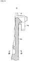
- caliper bracket
- Prior art date
- Legal status (The legal status is an assumption and is not a legal conclusion. Google has not performed a legal analysis and makes no representation as to the accuracy of the status listed.)
- Granted
Links
Images






Classifications
-
- F—MECHANICAL ENGINEERING; LIGHTING; HEATING; WEAPONS; BLASTING
- F16—ENGINEERING ELEMENTS AND UNITS; GENERAL MEASURES FOR PRODUCING AND MAINTAINING EFFECTIVE FUNCTIONING OF MACHINES OR INSTALLATIONS; THERMAL INSULATION IN GENERAL
- F16D—COUPLINGS FOR TRANSMITTING ROTATION; CLUTCHES; BRAKES
- F16D55/00—Brakes with substantially-radial braking surfaces pressed together in axial direction, e.g. disc brakes
-
- B—PERFORMING OPERATIONS; TRANSPORTING
- B60—VEHICLES IN GENERAL
- B60T—VEHICLE BRAKE CONTROL SYSTEMS OR PARTS THEREOF; BRAKE CONTROL SYSTEMS OR PARTS THEREOF, IN GENERAL; ARRANGEMENT OF BRAKING ELEMENTS ON VEHICLES IN GENERAL; PORTABLE DEVICES FOR PREVENTING UNWANTED MOVEMENT OF VEHICLES; VEHICLE MODIFICATIONS TO FACILITATE COOLING OF BRAKES
- B60T17/00—Component parts, details, or accessories of power brake systems not covered by groups B60T8/00, B60T13/00 or B60T15/00, or presenting other characteristic features
- B60T17/08—Brake cylinders other than ultimate actuators
- B60T17/088—Mounting arrangements
-
- F—MECHANICAL ENGINEERING; LIGHTING; HEATING; WEAPONS; BLASTING
- F16—ENGINEERING ELEMENTS AND UNITS; GENERAL MEASURES FOR PRODUCING AND MAINTAINING EFFECTIVE FUNCTIONING OF MACHINES OR INSTALLATIONS; THERMAL INSULATION IN GENERAL
- F16D—COUPLINGS FOR TRANSMITTING ROTATION; CLUTCHES; BRAKES
- F16D65/00—Parts or details
- F16D65/005—Components of axially engaging brakes not otherwise provided for
- F16D65/0068—Brake calipers
- F16D65/0075—Brake calipers assembled from a plurality of parts
-
- F—MECHANICAL ENGINEERING; LIGHTING; HEATING; WEAPONS; BLASTING
- F16—ENGINEERING ELEMENTS AND UNITS; GENERAL MEASURES FOR PRODUCING AND MAINTAINING EFFECTIVE FUNCTIONING OF MACHINES OR INSTALLATIONS; THERMAL INSULATION IN GENERAL
- F16D—COUPLINGS FOR TRANSMITTING ROTATION; CLUTCHES; BRAKES
- F16D65/00—Parts or details
- F16D65/02—Braking members; Mounting thereof
- F16D65/04—Bands, shoes or pads; Pivots or supporting members therefor
- F16D65/092—Bands, shoes or pads; Pivots or supporting members therefor for axially-engaging brakes, e.g. disc brakes
- F16D65/095—Pivots or supporting members therefor
-
- F—MECHANICAL ENGINEERING; LIGHTING; HEATING; WEAPONS; BLASTING
- F16—ENGINEERING ELEMENTS AND UNITS; GENERAL MEASURES FOR PRODUCING AND MAINTAINING EFFECTIVE FUNCTIONING OF MACHINES OR INSTALLATIONS; THERMAL INSULATION IN GENERAL
- F16D—COUPLINGS FOR TRANSMITTING ROTATION; CLUTCHES; BRAKES
- F16D55/00—Brakes with substantially-radial braking surfaces pressed together in axial direction, e.g. disc brakes
- F16D2055/0004—Parts or details of disc brakes
- F16D2055/0008—Brake supports
-
- F—MECHANICAL ENGINEERING; LIGHTING; HEATING; WEAPONS; BLASTING
- F16—ENGINEERING ELEMENTS AND UNITS; GENERAL MEASURES FOR PRODUCING AND MAINTAINING EFFECTIVE FUNCTIONING OF MACHINES OR INSTALLATIONS; THERMAL INSULATION IN GENERAL
- F16D—COUPLINGS FOR TRANSMITTING ROTATION; CLUTCHES; BRAKES
- F16D55/00—Brakes with substantially-radial braking surfaces pressed together in axial direction, e.g. disc brakes
- F16D2055/0004—Parts or details of disc brakes
- F16D2055/0008—Brake supports
- F16D2055/0012—Brake supports integral with vehicle suspension
-
- F—MECHANICAL ENGINEERING; LIGHTING; HEATING; WEAPONS; BLASTING
- F16—ENGINEERING ELEMENTS AND UNITS; GENERAL MEASURES FOR PRODUCING AND MAINTAINING EFFECTIVE FUNCTIONING OF MACHINES OR INSTALLATIONS; THERMAL INSULATION IN GENERAL
- F16D—COUPLINGS FOR TRANSMITTING ROTATION; CLUTCHES; BRAKES
- F16D55/00—Brakes with substantially-radial braking surfaces pressed together in axial direction, e.g. disc brakes
- F16D2055/0004—Parts or details of disc brakes
- F16D2055/0016—Brake calipers
-
- F—MECHANICAL ENGINEERING; LIGHTING; HEATING; WEAPONS; BLASTING
- F16—ENGINEERING ELEMENTS AND UNITS; GENERAL MEASURES FOR PRODUCING AND MAINTAINING EFFECTIVE FUNCTIONING OF MACHINES OR INSTALLATIONS; THERMAL INSULATION IN GENERAL
- F16D—COUPLINGS FOR TRANSMITTING ROTATION; CLUTCHES; BRAKES
- F16D2250/00—Manufacturing; Assembly
- F16D2250/0084—Assembly or disassembly
Definitions
- the present disclosure relates to a caliper bracket of a vehicle disk brake, and specifically, to a caliper bracket of a vehicle disk brake detachably attached to a swing arm and configured to support a caliper body.
- a caliper bracket of a vehicle disk brake attached to a swing arm on one side part of a disk rotor configured to rotate integrally with a rear wheel and including an axle coupling part coupled to an axle, a caliper body attaching part for attaching a caliper body of a disk brake, and a swing arm coupling part coupled to the swing arm (for example, refer to JP-A-2007-32750 ).
- a caliper bracket of a vehicle disk brake includes an axle coupling part, an extension part, a caliper attaching part and a swing arm coupling part.
- the axle coupling part to be disposed on an opposite side to a disk rotor configured to rotate integrally with a rear wheel and to be attached to a rear wheel axle passing through a center of the disk rotor.
- the extension part extending from the axle coupling part.
- the caliper attaching part provided on one side part of the extension part in a longitudinal direction and provided for attaching a caliper body of a disk brake.
- the swing arm coupling part provided on the other side part of the extension part in the longitudinal direction and to be coupled to a swing arm.
- the extension part is formed to linearly extend from the axle coupling part, and the swing arm coupling part is formed to have a cuboid shape protruding toward the opposite side to the disk rotor and capable of fitting with a coupling groove member provided for the swing arm.
- the swing arm coupling part may preferably be formed in parallel to the extension part.
- a sectional shape of the extension part perpendicular to the longitudinal direction may preferably be a quadrangular shape, an H-shape or U-shape.
- the extension part is made to linearly extend from the axle coupling part, so that it is possible to suppress a width of the extension part from increasing, to save a weight of the caliper bracket and to improve a layout freedom thereof.
- the swing arm coupling part is made to have a cuboid shape, so that it is possible to easily form the swing arm coupling part.
- the swing arm coupling part is provided in parallel to the extension part, so that it is possible to further suppress the width of the extension part from increasing.
- the sectional shape of the extension part perpendicular to the longitudinal direction is made to have a quadrangular shape, so that it is possible to easily cast the caliper bracket and to obtain a favorable outer shape.
- the sectional shape of the extension part perpendicular to the longitudinal direction is made to have an H-shape, so that it is possible to further save the weight, and when casting the caliper bracket, it is possible to improve a running property of molten metal.
- the sectional shape of the extension part perpendicular to the longitudinal direction is made to have a U-shape, so that it is possible to further save the weight, and when processing the extension part, it is possible to form the U-shape by cutting processing only in one direction and thus to easily process the extension part.
- FIGS. 1 to 9 depict a first embodiment example of the present disclosure
- an arrow A indicates a rotating direction of a disk rotor configured to rotate integrally with a wheel during forward travel of a vehicle
- a disk turn-out side and a disk turn-in side indicate those during the forward travel of the vehicle.
- a vehicle disk brake 1 includes a disk rotor 2 configured to rotate integrally with a rear wheel, a caliper bracket 4 attached to a swing arm 3 and disposed on a side of the disk rotor 2 opposite to the rear wheel, a caliper body 6 supported to the caliper bracket 4 via slide pins 5a and 5b so as to be movable in an axial direction of a disk, and a pair of friction pads 7 and 7 disposed between an action part 6a and a reaction part 6b of the caliper body 6 while facing each other with the disk rotor 2 being interposed therebetween.
- the swing arm 3 is formed on a tip end side with an axle insertion hole 3a for inserting an axle 8 of the rear wheel, and is attached on a base end side with a coupling groove member 3b for coupling the caliper bracket 4.
- the coupling groove member 3b has a U-shaped section having a pair of protrusion pieces 3c and 3c parallel to the swing arm 3 and a plane part 3d coupling the protrusion pieces 3c and 3c and parallel to the swing arm 3.
- the caliper bracket 4 has an axle coupling part 4a to be coupled to the axle 8 passing through a center of the disk rotor 2, an extension part 4b extending from the axle coupling part 4a toward a disk outer periphery side, a caliper attaching part 4c provided on one side part of the extension part 4b in a longitudinal direction, and a swing arm coupling part 4d provided on the other side part of the extension part 4b in the longitudinal direction.
- the axle coupling part 4a has a through-hole 4e in which the axle 8 is to be inserted, and a cover attaching arm 4f for attaching a cover configured to protect a vehicle body.
- the extension part 4b linearly extends from the axle coupling part 4a toward the disk outer periphery side, and a sectional shape thereof perpendicular to the longitudinal direction is an H-shape.
- the swing arm coupling part 4d has a cuboid shape parallel to the extension part 4b, protruding toward an opposite side to the disk rotor, and to be slidably coupled to the coupling groove member 3b.
- the caliper attaching part 4c has a turn-out side caliper support arm 4g protruding from a tip end side of the extension part 4b toward an upper side of the vehicle body, a turn-in side caliper support arm 4h protruding from an intermediate part of the extension part 4b in a disk turn-in side direction with respect to the turn-out side caliper support arm 4g, and an accommodation part 4i for friction pad provided between the turn-out side caliper support arm 4g and the turn-in side caliper support arm 4h.
- a side surface of the turn-out side caliper support arm 4g facing toward the accommodation part is provided with a torque receiving part 4j having a U-shape, a caliper support arm 4k striding an outer periphery of the disk rotor 2 protrudes from a tip end side of the turn-out side caliper support arm 4g in the axial direction of the disk, and the caliper support arm 4k is formed with a bag-shaped slide pin insertion hole 4m.
- the accommodation part 4i is formed so that a bottom surface 4n facing inner surfaces 7a of the friction pads 7 and 7 in a radial direction of the disk is substantially perpendicular to the extension part 4b.
- cover attaching arms 4f protrude from tip end portions of the turn-out side caliper support arm 4g and the turn-in side caliper support arm 4h, respectively.
- the caliper body 6 is configured by coupling the action part 6a and the reaction part 6b disposed at both sides of the disk rotor 2 by a bridge part 6c striding the outer periphery of the disk rotor 2.
- the action part 6a is provided with a bottomed cylinder hole 6d, and the pair of friction pads 7 and 7 is disposed between the action part 6a and the reaction part 6b while facing each other with the disk rotor 2 being interposed therebetween.
- Vehicle body mounting arms 6e and 6f protrude from the action part 6a toward the disk turn-out side and the inner side in the radial direction of the disk, and guide arms 6g and 6g protrude on the disk turn-in side of the action part 6a and the reaction part 6b.
- the cylinder hole 6d is formed to have a bottomed cylindrical shape with opening toward the disk rotor, a piston 9 is movably inserted therein, and a hydraulic chamber 10 is demarcated on a bottom side of the cylinder hole 6d.
- the caliper body 6 is supported to be movable in an axial direction of the disk rotor by making the slide pin 5a protrude from the vehicle body mounting arm 6e toward the disk rotor, inserting the slide pin 5a in the slide pin insertion hole 4m of the caliper bracket 4, making the slide pin 5b protrude from a slide pin attaching part 4p of the caliper bracket 4 toward an opposite side to the disk rotor, and inserting the slide pin 5b in the vehicle body mounting arm 6f of the caliper body 6. Also, the reaction part 6b is provided with a reactive force claw 6h.
- Each friction pad 7 is configured by bonding a lining 7b to be in sliding contact with a side surface of the disk rotor 2 to a metallic back plate 7c, and is supported to be movable in the axial direction of the disk by hanging and holding the disk turn-in side of the back plate 7c by a hanger pin 11 to be bridged to the guide arms 6g and 6g, and holding a lug piece 7d protruding toward the disk turn-out side of the back plate 7c in the torque receiving part 4j of the caliper bracket 4.
- the vehicle disk brake 1 formed in the above manner pushes the piston 9 toward the disk rotor, thereby pressing the friction pad 7 on the action part side to one side surface of the disk rotor 2.
- the caliper body 6 is moved toward the action part while being guided to the slide pins 5a and 5b by the reaction, and the reactive force claw 6h presses the friction pad 7 on the reaction part side to the other side surface of the disk rotor 2, so that a braking operation is performed.
- the extension part 4b linearly extends from the axle coupling part 4a toward the disk outer periphery side, and the swing arm coupling part 4d having a cuboid shape is provided in parallel to the extension part 4b, so that it is possible to suppress a width of the extension part 4b from increasing, to reduce a weight of the caliper bracket 4 and to improve layout freedom thereof.
- the bottom surface 4n of the accommodation part 4i for the friction pad 7, which is provided for the caliper attaching part 4c, is provided perpendicularly to the extension part 4b, so that it is possible to shorten a distance between the accommodation part 4i and the swing arm coupling part 4d, and to further reduce the weight of the caliper bracket 4 and to further improve the layout freedom thereof.
- a sectional shape of the extension part 4b perpendicular to the longitudinal direction is made to have an H-shape, so that it is possible to facilitate molding and processing of the caliper bracket 4, to save the weight and to secure the rigidness of the caliper bracket 4.
- the accommodation part 4i provided for the caliper attaching part 4c has the bottom surface 4n, which faces the inner surfaces 7a of the friction pads 7 and 7 in the radial direction of the disk and is formed substantially perpendicularly to the extension part 4b, and the torque receiving part 4j provided on the side surface of the turn-out side caliper support arm 4g facing toward the accommodation part and configured to receive the torque from the friction pads 7 and 7. Therefore, it is possible to favorably receive the torque, which is to be applied upon the barking, with the caliper bracket 4 via the torque receiving part 4j.
- FIGS. 10 to 15 depict other embodiment examples of the present disclosure.
- the constitutional elements, which are similar to the first embodiment example, are denoted with the same reference signs, and the detailed descriptions thereof are omitted.
- FIGS. 10 to 12 depict a second embodiment example of the present disclosure.
- an extension part 12a of a caliper bracket 12 linearly extends from the axle coupling part 4a toward the disk outer periphery side, and a sectional shape perpendicular to the longitudinal direction is made to have a quadrangular shape.
- a sectional shape perpendicular to the longitudinal direction is made to have a quadrangular shape.
- FIGS. 13 to 15 depict a third embodiment example of the present disclosure.
- an extension part 13a of a caliper bracket 13 linearly extends from the axle coupling part 4a toward the disk outer periphery side, and a sectional shape perpendicular to the longitudinal direction is made to have a U-shape.
- a sectional shape perpendicular to the longitudinal direction is made to have a U-shape.
- the swing arm coupling part may not be provided in parallel to the extension part.
- a sectional shape of the extension part perpendicular to the longitudinal direction is not limited to the H-shape, the quadrangular shape, and the U-shape.
- the shape of the caliper body may be arbitrarily formed, and the shape of the caliper attaching part of the caliper bracket may also be appropriately changed, in correspondence to the type of the caliper body to be attached.
Landscapes
- Engineering & Computer Science (AREA)
- General Engineering & Computer Science (AREA)
- Mechanical Engineering (AREA)
- Transportation (AREA)
- Braking Arrangements (AREA)
Abstract
Description
- This application is based upon and claims the benefit of priority from prior Japanese patent application Nos.
2018-187526, filed on October 2, 2018 2019-147057, filed on August 09, 2019 - The present disclosure relates to a caliper bracket of a vehicle disk brake, and specifically, to a caliper bracket of a vehicle disk brake detachably attached to a swing arm and configured to support a caliper body.
- In the related art, there is known a caliper bracket of a vehicle disk brake attached to a swing arm on one side part of a disk rotor configured to rotate integrally with a rear wheel, and including an axle coupling part coupled to an axle, a caliper body attaching part for attaching a caliper body of a disk brake, and a swing arm coupling part coupled to the swing arm (for example, refer to
JP-A-2007-32750 - However, according to the caliper bracket of a vehicle disk brake disclosed in
JP-A-2007-32750 - It is therefore an object of the present disclosure to provide a caliper bracket of a vehicle disk brake making it possible to save a weight and to improve a layout freedom.
- A caliper bracket of a vehicle disk brake includes an axle coupling part, an extension part, a caliper attaching part and a swing arm coupling part. The axle coupling part to be disposed on an opposite side to a disk rotor configured to rotate integrally with a rear wheel and to be attached to a rear wheel axle passing through a center of the disk rotor. The extension part extending from the axle coupling part. The caliper attaching part provided on one side part of the extension part in a longitudinal direction and provided for attaching a caliper body of a disk brake. The swing arm coupling part provided on the other side part of the extension part in the longitudinal direction and to be coupled to a swing arm. The extension part is formed to linearly extend from the axle coupling part, and the swing arm coupling part is formed to have a cuboid shape protruding toward the opposite side to the disk rotor and capable of fitting with a coupling groove member provided for the swing arm.
- The swing arm coupling part may preferably be formed in parallel to the extension part.
- A sectional shape of the extension part perpendicular to the longitudinal direction may preferably be a quadrangular shape, an H-shape or U-shape.
- According to the caliper bracket of a vehicle disk brake of the present disclosure, the extension part is made to linearly extend from the axle coupling part, so that it is possible to suppress a width of the extension part from increasing, to save a weight of the caliper bracket and to improve a layout freedom thereof. Also, the swing arm coupling part is made to have a cuboid shape, so that it is possible to easily form the swing arm coupling part.
- Also, the swing arm coupling part is provided in parallel to the extension part, so that it is possible to further suppress the width of the extension part from increasing.
- Also, the sectional shape of the extension part perpendicular to the longitudinal direction is made to have a quadrangular shape, so that it is possible to easily cast the caliper bracket and to obtain a favorable outer shape. Also, the sectional shape of the extension part perpendicular to the longitudinal direction is made to have an H-shape, so that it is possible to further save the weight, and when casting the caliper bracket, it is possible to improve a running property of molten metal. Also, the sectional shape of the extension part perpendicular to the longitudinal direction is made to have a U-shape, so that it is possible to further save the weight, and when processing the extension part, it is possible to form the U-shape by cutting processing only in one direction and thus to easily process the extension part.
-
-
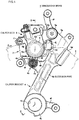
FIG. 1 is a front view of a vehicle disk brake, depicting a first embodiment example of the present disclosure. -
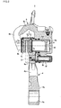
FIG. 2 is a sectional view taken along a line II-II ofFIG. 1 . -
FIG. 3 is a partial sectional plan view of the vehicle disk brake, depicting the first embodiment example of the present disclosure. -
FIG. 4 is a sectional view taken along a line IV-IV ofFIG. 3 . -
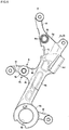
FIG. 5 is a front view of a caliper bracket, depicting the first embodiment example of the present disclosure. -
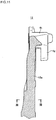
FIG. 6 is a sectional view taken along a line VI-VI ofFIG. 5 . -
FIG. 7 is a sectional view taken along a line VII-VII ofFIG. 6 . -
FIG. 8 is a front view of the vehicle disk brake attached to a vehicle body, depicting the first embodiment example of the present disclosure. -
FIG. 9 is a partial sectional side view of the vehicle disk brake attached to the vehicle body, likeFIG. 8 . -
FIG. 10 is a front view of a caliper bracket, depicting a second embodiment example of the present disclosure. -
FIG. 11 is a sectional view taken along a line XI-XI ofFIG. 10 . -
FIG. 12 is a sectional view taken along a line XII-XII ofFIG. 11 . -
FIG. 13 is a front view of a caliper bracket, depicting a third embodiment example of the present disclosure. -
FIG. 14 is a sectional view taken along a line XIV-XIV ofFIG. 13 . -
FIG. 15 is a sectional view taken along a line XV-XV ofFIG. 14 . -
FIGS. 1 to 9 depict a first embodiment example of the present disclosure, an arrow A indicates a rotating direction of a disk rotor configured to rotate integrally with a wheel during forward travel of a vehicle, and a disk turn-out side and a disk turn-in side indicate those during the forward travel of the vehicle. - A
vehicle disk brake 1 includes adisk rotor 2 configured to rotate integrally with a rear wheel, acaliper bracket 4 attached to a swing arm 3 and disposed on a side of thedisk rotor 2 opposite to the rear wheel, acaliper body 6 supported to thecaliper bracket 4 viaslide pins friction pads action part 6a and areaction part 6b of thecaliper body 6 while facing each other with thedisk rotor 2 being interposed therebetween. - The swing arm 3 is formed on a tip end side with an
axle insertion hole 3a for inserting anaxle 8 of the rear wheel, and is attached on a base end side with acoupling groove member 3b for coupling thecaliper bracket 4. Thecoupling groove member 3b has a U-shaped section having a pair ofprotrusion pieces plane part 3d coupling theprotrusion pieces - The
caliper bracket 4 has anaxle coupling part 4a to be coupled to theaxle 8 passing through a center of thedisk rotor 2, anextension part 4b extending from theaxle coupling part 4a toward a disk outer periphery side, acaliper attaching part 4c provided on one side part of theextension part 4b in a longitudinal direction, and a swingarm coupling part 4d provided on the other side part of theextension part 4b in the longitudinal direction. - The
axle coupling part 4a has a through-hole 4e in which theaxle 8 is to be inserted, and acover attaching arm 4f for attaching a cover configured to protect a vehicle body. Theextension part 4b linearly extends from theaxle coupling part 4a toward the disk outer periphery side, and a sectional shape thereof perpendicular to the longitudinal direction is an H-shape. The swingarm coupling part 4d has a cuboid shape parallel to theextension part 4b, protruding toward an opposite side to the disk rotor, and to be slidably coupled to thecoupling groove member 3b. - The
caliper attaching part 4c has a turn-out sidecaliper support arm 4g protruding from a tip end side of theextension part 4b toward an upper side of the vehicle body, a turn-in sidecaliper support arm 4h protruding from an intermediate part of theextension part 4b in a disk turn-in side direction with respect to the turn-out sidecaliper support arm 4g, and anaccommodation part 4i for friction pad provided between the turn-out sidecaliper support arm 4g and the turn-in sidecaliper support arm 4h. A side surface of the turn-out sidecaliper support arm 4g facing toward the accommodation part is provided with atorque receiving part 4j having a U-shape, acaliper support arm 4k striding an outer periphery of thedisk rotor 2 protrudes from a tip end side of the turn-out sidecaliper support arm 4g in the axial direction of the disk, and thecaliper support arm 4k is formed with a bag-shaped slidepin insertion hole 4m. Also, theaccommodation part 4i is formed so that abottom surface 4n facinginner surfaces 7a of thefriction pads extension part 4b. Also,cover attaching arms 4f protrude from tip end portions of the turn-out sidecaliper support arm 4g and the turn-in sidecaliper support arm 4h, respectively. - The
caliper body 6 is configured by coupling theaction part 6a and thereaction part 6b disposed at both sides of thedisk rotor 2 by abridge part 6c striding the outer periphery of thedisk rotor 2. Theaction part 6a is provided with a bottomedcylinder hole 6d, and the pair offriction pads action part 6a and thereaction part 6b while facing each other with thedisk rotor 2 being interposed therebetween. - Vehicle
body mounting arms action part 6a toward the disk turn-out side and the inner side in the radial direction of the disk, and guidearms action part 6a and thereaction part 6b. Thecylinder hole 6d is formed to have a bottomed cylindrical shape with opening toward the disk rotor, apiston 9 is movably inserted therein, and ahydraulic chamber 10 is demarcated on a bottom side of thecylinder hole 6d. - The
caliper body 6 is supported to be movable in an axial direction of the disk rotor by making theslide pin 5a protrude from the vehiclebody mounting arm 6e toward the disk rotor, inserting theslide pin 5a in the slidepin insertion hole 4m of thecaliper bracket 4, making theslide pin 5b protrude from a slidepin attaching part 4p of thecaliper bracket 4 toward an opposite side to the disk rotor, and inserting theslide pin 5b in the vehiclebody mounting arm 6f of thecaliper body 6. Also, thereaction part 6b is provided with areactive force claw 6h. - Each
friction pad 7 is configured by bonding alining 7b to be in sliding contact with a side surface of thedisk rotor 2 to ametallic back plate 7c, and is supported to be movable in the axial direction of the disk by hanging and holding the disk turn-in side of theback plate 7c by ahanger pin 11 to be bridged to theguide arms lug piece 7d protruding toward the disk turn-out side of theback plate 7c in thetorque receiving part 4j of thecaliper bracket 4. - Upon the braking, when an operating fluid of which a pressure has been increased by a separate hydraulic master cylinder is supplied to the
hydraulic chamber 10, thevehicle disk brake 1 formed in the above manner pushes thepiston 9 toward the disk rotor, thereby pressing thefriction pad 7 on the action part side to one side surface of thedisk rotor 2. Subsequently, thecaliper body 6 is moved toward the action part while being guided to theslide pins reactive force claw 6h presses thefriction pad 7 on the reaction part side to the other side surface of thedisk rotor 2, so that a braking operation is performed. - As described above, according to the
caliper bracket 4 of the first embodiment example, theextension part 4b linearly extends from theaxle coupling part 4a toward the disk outer periphery side, and the swingarm coupling part 4d having a cuboid shape is provided in parallel to theextension part 4b, so that it is possible to suppress a width of theextension part 4b from increasing, to reduce a weight of thecaliper bracket 4 and to improve layout freedom thereof. Also, thebottom surface 4n of theaccommodation part 4i for thefriction pad 7, which is provided for thecaliper attaching part 4c, is provided perpendicularly to theextension part 4b, so that it is possible to shorten a distance between theaccommodation part 4i and the swingarm coupling part 4d, and to further reduce the weight of thecaliper bracket 4 and to further improve the layout freedom thereof. Also, a sectional shape of theextension part 4b perpendicular to the longitudinal direction is made to have an H-shape, so that it is possible to facilitate molding and processing of thecaliper bracket 4, to save the weight and to secure the rigidness of thecaliper bracket 4. Also, theaccommodation part 4i provided for thecaliper attaching part 4c has thebottom surface 4n, which faces theinner surfaces 7a of thefriction pads extension part 4b, and thetorque receiving part 4j provided on the side surface of the turn-out sidecaliper support arm 4g facing toward the accommodation part and configured to receive the torque from thefriction pads caliper bracket 4 via thetorque receiving part 4j. -
FIGS. 10 to 15 depict other embodiment examples of the present disclosure. The constitutional elements, which are similar to the first embodiment example, are denoted with the same reference signs, and the detailed descriptions thereof are omitted. -
FIGS. 10 to 12 depict a second embodiment example of the present disclosure. In the second embodiment example, anextension part 12a of acaliper bracket 12 linearly extends from theaxle coupling part 4a toward the disk outer periphery side, and a sectional shape perpendicular to the longitudinal direction is made to have a quadrangular shape. Thereby, it is possible to easily cast thecaliper bracket 12 of the second embodiment example and to obtain a favorable outer shape. -
FIGS. 13 to 15 depict a third embodiment example of the present disclosure. In the third embodiment example, anextension part 13a of acaliper bracket 13 linearly extends from theaxle coupling part 4a toward the disk outer periphery side, and a sectional shape perpendicular to the longitudinal direction is made to have a U-shape. Thereby, it is possible to further reduce the weight of thecaliper bracket 13 of the third embodiment example. Also, when cutting theextension part 13a into a U-shape, it is possible to form the U-shape by the cutting processing only in one direction, so that it is possible to easily form the extension part. - In the meantime, the present disclosure is not limited to the embodiment examples. For example, the swing arm coupling part may not be provided in parallel to the extension part. Also, a sectional shape of the extension part perpendicular to the longitudinal direction is not limited to the H-shape, the quadrangular shape, and the U-shape. Also, the shape of the caliper body may be arbitrarily formed, and the shape of the caliper attaching part of the caliper bracket may also be appropriately changed, in correspondence to the type of the caliper body to be attached.
Claims (5)
- A caliper bracket of a vehicle disk brake comprising:an axle coupling part to be disposed on an opposite side to a disk rotor configured to rotate integrally with a rear wheel and to be attached to a rear wheel axle passing through a center of the disk rotor;an extension part extending from the axle coupling part;a caliper attaching part provided on one side part of the extension part in a longitudinal direction and provided for attaching a caliper body of a disk brake; anda swing arm coupling part provided on the other side part of the extension part in the longitudinal direction and to be coupled to a swing arm,wherein the extension part is formed to linearly extend from the axle coupling part, and the swing arm coupling part is formed to have a cuboid shape protruding toward the opposite side to the disk rotor and capable of fitting with a coupling groove member provided for the swing arm.
- The caliper bracket of the vehicle disk brake according to Claim 1, wherein the swing arm coupling part is formed in parallel to the extension part.
- The caliper bracket of the vehicle disk brake according to Claim 1 or 2, wherein a sectional shape of the extension part perpendicular to the longitudinal direction is a quadrangular shape.
- The caliper bracket of the vehicle disk brake according to Claim 1 or 2, wherein a sectional shape of the extension part perpendicular to the longitudinal direction is an H-shape.
- The caliper bracket of the vehicle disk brake according to Claim 1 or 2, wherein a sectional shape of the extension part perpendicular to the longitudinal direction is a U-shape.
Applications Claiming Priority (2)
| Application Number | Priority Date | Filing Date | Title |
|---|---|---|---|
| JP2018187526 | 2018-10-02 | ||
| JP2019147057A JP7023260B2 (en) | 2018-10-02 | 2019-08-09 | Vehicle disc brake caliper bracket |
Publications (2)
| Publication Number | Publication Date |
|---|---|
| EP3633224A1 true EP3633224A1 (en) | 2020-04-08 |
| EP3633224B1 EP3633224B1 (en) | 2021-03-10 |
Family
ID=68136223
Family Applications (1)
| Application Number | Title | Priority Date | Filing Date |
|---|---|---|---|
| EP19201039.5A Active EP3633224B1 (en) | 2018-10-02 | 2019-10-02 | Caliper bracket for vehicle disk brake |
Country Status (2)
| Country | Link |
|---|---|
| US (1) | US11046296B2 (en) |
| EP (1) | EP3633224B1 (en) |
Cited By (3)
| Publication number | Priority date | Publication date | Assignee | Title |
|---|---|---|---|---|
| EP3943774A4 (en) * | 2019-03-19 | 2022-11-30 | Hitachi Astemo, Ltd. | CALIPER BODY FOR VEHICLE DISC BRAKE |
| IT202100014294A1 (en) | 2021-06-01 | 2022-12-01 | Brembo Spa | Floating caliper |
| IT202300028182A1 (en) | 2023-12-28 | 2025-06-28 | Brembo Spa | FLOATING BRAKE CALIPER OF A DISC BRAKE |
Families Citing this family (1)
| Publication number | Priority date | Publication date | Assignee | Title |
|---|---|---|---|---|
| US11788590B2 (en) * | 2021-05-26 | 2023-10-17 | Richard Mellick Zock | Rear brake conversion assembly for all-terrain vehicles |
Citations (5)
| Publication number | Priority date | Publication date | Assignee | Title |
|---|---|---|---|---|
| JPH11291969A (en) * | 1998-04-08 | 1999-10-26 | Suzuki Motor Corp | Motorcycle rear wheel brake mounting structure |
| JP2004036799A (en) * | 2002-07-04 | 2004-02-05 | Nissin Kogyo Co Ltd | Rear wheel brake for bar handle vehicles |
| JP2007032750A (en) | 2005-07-28 | 2007-02-08 | Nissin Kogyo Co Ltd | Caliper bracket for vehicle disc brake |
| JP2014070704A (en) * | 2012-09-28 | 2014-04-21 | Honda Motor Co Ltd | Brake caliper and saddle type vehicle provided with the same |
| EP3301319A1 (en) * | 2016-09-29 | 2018-04-04 | Honda Motor Co., Ltd. | Rear brake device of vehicle |
Family Cites Families (3)
| Publication number | Priority date | Publication date | Assignee | Title |
|---|---|---|---|---|
| JPH0441029Y2 (en) * | 1985-05-31 | 1992-09-25 | ||
| JP3848525B2 (en) * | 2000-09-08 | 2006-11-22 | 本田技研工業株式会社 | Motorcycle braking device |
| JP5873567B2 (en) * | 2012-11-01 | 2016-03-01 | 本田技研工業株式会社 | Brake caliper arrangement structure for motorcycles |
-
2019
- 2019-09-30 US US16/587,945 patent/US11046296B2/en active Active
- 2019-10-02 EP EP19201039.5A patent/EP3633224B1/en active Active
Patent Citations (5)
| Publication number | Priority date | Publication date | Assignee | Title |
|---|---|---|---|---|
| JPH11291969A (en) * | 1998-04-08 | 1999-10-26 | Suzuki Motor Corp | Motorcycle rear wheel brake mounting structure |
| JP2004036799A (en) * | 2002-07-04 | 2004-02-05 | Nissin Kogyo Co Ltd | Rear wheel brake for bar handle vehicles |
| JP2007032750A (en) | 2005-07-28 | 2007-02-08 | Nissin Kogyo Co Ltd | Caliper bracket for vehicle disc brake |
| JP2014070704A (en) * | 2012-09-28 | 2014-04-21 | Honda Motor Co Ltd | Brake caliper and saddle type vehicle provided with the same |
| EP3301319A1 (en) * | 2016-09-29 | 2018-04-04 | Honda Motor Co., Ltd. | Rear brake device of vehicle |
Cited By (4)
| Publication number | Priority date | Publication date | Assignee | Title |
|---|---|---|---|---|
| EP3943774A4 (en) * | 2019-03-19 | 2022-11-30 | Hitachi Astemo, Ltd. | CALIPER BODY FOR VEHICLE DISC BRAKE |
| IT202100014294A1 (en) | 2021-06-01 | 2022-12-01 | Brembo Spa | Floating caliper |
| EP4098902A1 (en) | 2021-06-01 | 2022-12-07 | Brembo S.p.A. | Floating caliper |
| IT202300028182A1 (en) | 2023-12-28 | 2025-06-28 | Brembo Spa | FLOATING BRAKE CALIPER OF A DISC BRAKE |
Also Published As
| Publication number | Publication date |
|---|---|
| US11046296B2 (en) | 2021-06-29 |
| EP3633224B1 (en) | 2021-03-10 |
| US20200101960A1 (en) | 2020-04-02 |
Similar Documents
| Publication | Publication Date | Title |
|---|---|---|
| US11046296B2 (en) | Caliper bracket of vehicle disk brake | |
| US9377070B2 (en) | Vehicle disc brake | |
| JP4741693B2 (en) | Decorative plate mounting structure | |
| US9279466B2 (en) | Vehicle disc brake | |
| EP3809009A1 (en) | Vehicular disc brake | |
| JP2015148318A (en) | Vehicle disc brake | |
| JP2015052347A (en) | Disk brake for vehicle | |
| US9353809B2 (en) | Vehicle disc brake | |
| EP3943774A1 (en) | Caliper body for vehicle disc brake | |
| JP4783822B2 (en) | Caliper body for disc brakes for vehicles | |
| JP4881864B2 (en) | Disc brake with small carrier | |
| JP6928564B2 (en) | Vehicle disc brakes | |
| JP4474474B2 (en) | Pin slide type vehicle disc brake | |
| JP6579969B2 (en) | Disc brake | |
| JP7023260B2 (en) | Vehicle disc brake caliper bracket | |
| JP2014228083A (en) | Disk brake for vehicle | |
| JP4028405B2 (en) | Pin slide type caliper body for disc brakes for vehicles | |
| JP6052615B2 (en) | Reaction type disc brake | |
| CN104246271B (en) | Disk brake | |
| JP3729633B2 (en) | Vehicle disc brake | |
| JP4318575B2 (en) | Hydraulic vehicle disc brake | |
| JP2020159368A (en) | Vehicle disc brakes | |
| JP2009127646A (en) | Pin slide disc brakes for vehicles | |
| JP2604722Y2 (en) | Friction pads for vehicle disc brakes | |
| JP6144614B2 (en) | Vehicle disc brake |
Legal Events
| Date | Code | Title | Description |
|---|---|---|---|
| PUAI | Public reference made under article 153(3) epc to a published international application that has entered the european phase |
Free format text: ORIGINAL CODE: 0009012 |
|
| STAA | Information on the status of an ep patent application or granted ep patent |
Free format text: STATUS: THE APPLICATION HAS BEEN PUBLISHED |
|
| AK | Designated contracting states |
Kind code of ref document: A1 Designated state(s): AL AT BE BG CH CY CZ DE DK EE ES FI FR GB GR HR HU IE IS IT LI LT LU LV MC MK MT NL NO PL PT RO RS SE SI SK SM TR |
|
| AX | Request for extension of the european patent |
Extension state: BA ME |
|
| STAA | Information on the status of an ep patent application or granted ep patent |
Free format text: STATUS: REQUEST FOR EXAMINATION WAS MADE |
|
| 17P | Request for examination filed |
Effective date: 20200629 |
|
| RBV | Designated contracting states (corrected) |
Designated state(s): AL AT BE BG CH CY CZ DE DK EE ES FI FR GB GR HR HU IE IS IT LI LT LU LV MC MK MT NL NO PL PT RO RS SE SI SK SM TR |
|
| GRAP | Despatch of communication of intention to grant a patent |
Free format text: ORIGINAL CODE: EPIDOSNIGR1 |
|
| STAA | Information on the status of an ep patent application or granted ep patent |
Free format text: STATUS: GRANT OF PATENT IS INTENDED |
|
| INTG | Intention to grant announced |
Effective date: 20200917 |
|
| GRAS | Grant fee paid |
Free format text: ORIGINAL CODE: EPIDOSNIGR3 |
|
| GRAA | (expected) grant |
Free format text: ORIGINAL CODE: 0009210 |
|
| STAA | Information on the status of an ep patent application or granted ep patent |
Free format text: STATUS: THE PATENT HAS BEEN GRANTED |
|
| AK | Designated contracting states |
Kind code of ref document: B1 Designated state(s): AL AT BE BG CH CY CZ DE DK EE ES FI FR GB GR HR HU IE IS IT LI LT LU LV MC MK MT NL NO PL PT RO RS SE SI SK SM TR |
|
| REG | Reference to a national code |
Ref country code: GB Ref legal event code: FG4D |
|
| REG | Reference to a national code |
Ref country code: CH Ref legal event code: EP Ref country code: AT Ref legal event code: REF Ref document number: 1370128 Country of ref document: AT Kind code of ref document: T Effective date: 20210315 |
|
| REG | Reference to a national code |
Ref country code: IE Ref legal event code: FG4D |
|
| REG | Reference to a national code |
Ref country code: DE Ref legal event code: R096 Ref document number: 602019003099 Country of ref document: DE |
|
| REG | Reference to a national code |
Ref country code: CH Ref legal event code: PK Free format text: BERICHTIGUNGEN |
|
| RAP2 | Party data changed (patent owner data changed or rights of a patent transferred) |
Owner name: HITACHI ASTEMO, LTD. |
|
| RIN2 | Information on inventor provided after grant (corrected) |
Inventor name: UEHARA, KAZUMASA |
|
| REG | Reference to a national code |
Ref country code: LT Ref legal event code: MG9D |
|
| PG25 | Lapsed in a contracting state [announced via postgrant information from national office to epo] |
Ref country code: NO Free format text: LAPSE BECAUSE OF FAILURE TO SUBMIT A TRANSLATION OF THE DESCRIPTION OR TO PAY THE FEE WITHIN THE PRESCRIBED TIME-LIMIT Effective date: 20210610 Ref country code: LT Free format text: LAPSE BECAUSE OF FAILURE TO SUBMIT A TRANSLATION OF THE DESCRIPTION OR TO PAY THE FEE WITHIN THE PRESCRIBED TIME-LIMIT Effective date: 20210310 Ref country code: GR Free format text: LAPSE BECAUSE OF FAILURE TO SUBMIT A TRANSLATION OF THE DESCRIPTION OR TO PAY THE FEE WITHIN THE PRESCRIBED TIME-LIMIT Effective date: 20210611 Ref country code: FI Free format text: LAPSE BECAUSE OF FAILURE TO SUBMIT A TRANSLATION OF THE DESCRIPTION OR TO PAY THE FEE WITHIN THE PRESCRIBED TIME-LIMIT Effective date: 20210310 Ref country code: BG Free format text: LAPSE BECAUSE OF FAILURE TO SUBMIT A TRANSLATION OF THE DESCRIPTION OR TO PAY THE FEE WITHIN THE PRESCRIBED TIME-LIMIT Effective date: 20210610 Ref country code: HR Free format text: LAPSE BECAUSE OF FAILURE TO SUBMIT A TRANSLATION OF THE DESCRIPTION OR TO PAY THE FEE WITHIN THE PRESCRIBED TIME-LIMIT Effective date: 20210310 |
|
| REG | Reference to a national code |
Ref country code: NL Ref legal event code: MP Effective date: 20210310 |
|
| PG25 | Lapsed in a contracting state [announced via postgrant information from national office to epo] |
Ref country code: LV Free format text: LAPSE BECAUSE OF FAILURE TO SUBMIT A TRANSLATION OF THE DESCRIPTION OR TO PAY THE FEE WITHIN THE PRESCRIBED TIME-LIMIT Effective date: 20210310 Ref country code: RS Free format text: LAPSE BECAUSE OF FAILURE TO SUBMIT A TRANSLATION OF THE DESCRIPTION OR TO PAY THE FEE WITHIN THE PRESCRIBED TIME-LIMIT Effective date: 20210310 Ref country code: SE Free format text: LAPSE BECAUSE OF FAILURE TO SUBMIT A TRANSLATION OF THE DESCRIPTION OR TO PAY THE FEE WITHIN THE PRESCRIBED TIME-LIMIT Effective date: 20210310 |
|
| PG25 | Lapsed in a contracting state [announced via postgrant information from national office to epo] |
Ref country code: NL Free format text: LAPSE BECAUSE OF FAILURE TO SUBMIT A TRANSLATION OF THE DESCRIPTION OR TO PAY THE FEE WITHIN THE PRESCRIBED TIME-LIMIT Effective date: 20210310 |
|
| PG25 | Lapsed in a contracting state [announced via postgrant information from national office to epo] |
Ref country code: EE Free format text: LAPSE BECAUSE OF FAILURE TO SUBMIT A TRANSLATION OF THE DESCRIPTION OR TO PAY THE FEE WITHIN THE PRESCRIBED TIME-LIMIT Effective date: 20210310 Ref country code: CZ Free format text: LAPSE BECAUSE OF FAILURE TO SUBMIT A TRANSLATION OF THE DESCRIPTION OR TO PAY THE FEE WITHIN THE PRESCRIBED TIME-LIMIT Effective date: 20210310 Ref country code: SM Free format text: LAPSE BECAUSE OF FAILURE TO SUBMIT A TRANSLATION OF THE DESCRIPTION OR TO PAY THE FEE WITHIN THE PRESCRIBED TIME-LIMIT Effective date: 20210310 |
|
| PG25 | Lapsed in a contracting state [announced via postgrant information from national office to epo] |
Ref country code: PL Free format text: LAPSE BECAUSE OF FAILURE TO SUBMIT A TRANSLATION OF THE DESCRIPTION OR TO PAY THE FEE WITHIN THE PRESCRIBED TIME-LIMIT Effective date: 20210310 Ref country code: PT Free format text: LAPSE BECAUSE OF FAILURE TO SUBMIT A TRANSLATION OF THE DESCRIPTION OR TO PAY THE FEE WITHIN THE PRESCRIBED TIME-LIMIT Effective date: 20210712 Ref country code: RO Free format text: LAPSE BECAUSE OF FAILURE TO SUBMIT A TRANSLATION OF THE DESCRIPTION OR TO PAY THE FEE WITHIN THE PRESCRIBED TIME-LIMIT Effective date: 20210310 Ref country code: SK Free format text: LAPSE BECAUSE OF FAILURE TO SUBMIT A TRANSLATION OF THE DESCRIPTION OR TO PAY THE FEE WITHIN THE PRESCRIBED TIME-LIMIT Effective date: 20210310 Ref country code: IS Free format text: LAPSE BECAUSE OF FAILURE TO SUBMIT A TRANSLATION OF THE DESCRIPTION OR TO PAY THE FEE WITHIN THE PRESCRIBED TIME-LIMIT Effective date: 20210710 |
|
| REG | Reference to a national code |
Ref country code: DE Ref legal event code: R097 Ref document number: 602019003099 Country of ref document: DE |
|
| PLBE | No opposition filed within time limit |
Free format text: ORIGINAL CODE: 0009261 |
|
| STAA | Information on the status of an ep patent application or granted ep patent |
Free format text: STATUS: NO OPPOSITION FILED WITHIN TIME LIMIT |
|
| PG25 | Lapsed in a contracting state [announced via postgrant information from national office to epo] |
Ref country code: DK Free format text: LAPSE BECAUSE OF FAILURE TO SUBMIT A TRANSLATION OF THE DESCRIPTION OR TO PAY THE FEE WITHIN THE PRESCRIBED TIME-LIMIT Effective date: 20210310 Ref country code: AL Free format text: LAPSE BECAUSE OF FAILURE TO SUBMIT A TRANSLATION OF THE DESCRIPTION OR TO PAY THE FEE WITHIN THE PRESCRIBED TIME-LIMIT Effective date: 20210310 Ref country code: ES Free format text: LAPSE BECAUSE OF FAILURE TO SUBMIT A TRANSLATION OF THE DESCRIPTION OR TO PAY THE FEE WITHIN THE PRESCRIBED TIME-LIMIT Effective date: 20210310 |
|
| 26N | No opposition filed |
Effective date: 20211213 |
|
| PG25 | Lapsed in a contracting state [announced via postgrant information from national office to epo] |
Ref country code: SI Free format text: LAPSE BECAUSE OF FAILURE TO SUBMIT A TRANSLATION OF THE DESCRIPTION OR TO PAY THE FEE WITHIN THE PRESCRIBED TIME-LIMIT Effective date: 20210310 |
|
| REG | Reference to a national code |
Ref country code: DE Ref legal event code: R119 Ref document number: 602019003099 Country of ref document: DE |
|
| REG | Reference to a national code |
Ref country code: AT Ref legal event code: PC Ref document number: 1370128 Country of ref document: AT Kind code of ref document: T Owner name: HITACHI ASTEMO, LTD., JP Effective date: 20220321 |
|
| PG25 | Lapsed in a contracting state [announced via postgrant information from national office to epo] |
Ref country code: IS Free format text: LAPSE BECAUSE OF FAILURE TO SUBMIT A TRANSLATION OF THE DESCRIPTION OR TO PAY THE FEE WITHIN THE PRESCRIBED TIME-LIMIT Effective date: 20210710 |
|
| REG | Reference to a national code |
Ref country code: BE Ref legal event code: MM Effective date: 20211031 |
|
| PG25 | Lapsed in a contracting state [announced via postgrant information from national office to epo] |
Ref country code: MC Free format text: LAPSE BECAUSE OF FAILURE TO SUBMIT A TRANSLATION OF THE DESCRIPTION OR TO PAY THE FEE WITHIN THE PRESCRIBED TIME-LIMIT Effective date: 20210310 |
|
| PG25 | Lapsed in a contracting state [announced via postgrant information from national office to epo] |
Ref country code: LU Free format text: LAPSE BECAUSE OF NON-PAYMENT OF DUE FEES Effective date: 20211002 Ref country code: DE Free format text: LAPSE BECAUSE OF NON-PAYMENT OF DUE FEES Effective date: 20220503 Ref country code: BE Free format text: LAPSE BECAUSE OF NON-PAYMENT OF DUE FEES Effective date: 20211031 |
|
| PG25 | Lapsed in a contracting state [announced via postgrant information from national office to epo] |
Ref country code: FR Free format text: LAPSE BECAUSE OF NON-PAYMENT OF DUE FEES Effective date: 20211031 |
|
| PG25 | Lapsed in a contracting state [announced via postgrant information from national office to epo] |
Ref country code: IE Free format text: LAPSE BECAUSE OF NON-PAYMENT OF DUE FEES Effective date: 20211002 |
|
| REG | Reference to a national code |
Ref country code: CH Ref legal event code: PL |
|
| PG25 | Lapsed in a contracting state [announced via postgrant information from national office to epo] |
Ref country code: CY Free format text: LAPSE BECAUSE OF FAILURE TO SUBMIT A TRANSLATION OF THE DESCRIPTION OR TO PAY THE FEE WITHIN THE PRESCRIBED TIME-LIMIT Effective date: 20210310 |
|
| PG25 | Lapsed in a contracting state [announced via postgrant information from national office to epo] |
Ref country code: LI Free format text: LAPSE BECAUSE OF NON-PAYMENT OF DUE FEES Effective date: 20221031 Ref country code: HU Free format text: LAPSE BECAUSE OF FAILURE TO SUBMIT A TRANSLATION OF THE DESCRIPTION OR TO PAY THE FEE WITHIN THE PRESCRIBED TIME-LIMIT; INVALID AB INITIO Effective date: 20191002 Ref country code: CH Free format text: LAPSE BECAUSE OF NON-PAYMENT OF DUE FEES Effective date: 20221031 |
|
| PG25 | Lapsed in a contracting state [announced via postgrant information from national office to epo] |
Ref country code: MK Free format text: LAPSE BECAUSE OF FAILURE TO SUBMIT A TRANSLATION OF THE DESCRIPTION OR TO PAY THE FEE WITHIN THE PRESCRIBED TIME-LIMIT Effective date: 20210310 |
|
| GBPC | Gb: european patent ceased through non-payment of renewal fee |
Effective date: 20231002 |
|
| PG25 | Lapsed in a contracting state [announced via postgrant information from national office to epo] |
Ref country code: GB Free format text: LAPSE BECAUSE OF NON-PAYMENT OF DUE FEES Effective date: 20231002 |
|
| PG25 | Lapsed in a contracting state [announced via postgrant information from national office to epo] |
Ref country code: GB Free format text: LAPSE BECAUSE OF NON-PAYMENT OF DUE FEES Effective date: 20231002 |
|
| PG25 | Lapsed in a contracting state [announced via postgrant information from national office to epo] |
Ref country code: MT Free format text: LAPSE BECAUSE OF FAILURE TO SUBMIT A TRANSLATION OF THE DESCRIPTION OR TO PAY THE FEE WITHIN THE PRESCRIBED TIME-LIMIT Effective date: 20210310 |
|
| REG | Reference to a national code |
Ref country code: AT Ref legal event code: UEP Ref document number: 1370128 Country of ref document: AT Kind code of ref document: T Effective date: 20210310 |
|
| PGFP | Annual fee paid to national office [announced via postgrant information from national office to epo] |
Ref country code: IT Payment date: 20250922 Year of fee payment: 7 |
|
| PG25 | Lapsed in a contracting state [announced via postgrant information from national office to epo] |
Ref country code: TR Free format text: LAPSE BECAUSE OF FAILURE TO SUBMIT A TRANSLATION OF THE DESCRIPTION OR TO PAY THE FEE WITHIN THE PRESCRIBED TIME-LIMIT Effective date: 20210310 |
|
| PGFP | Annual fee paid to national office [announced via postgrant information from national office to epo] |
Ref country code: AT Payment date: 20250925 Year of fee payment: 7 |