EP3633198A1 - Scroll compressor - Google Patents
Scroll compressor Download PDFInfo
- Publication number
- EP3633198A1 EP3633198A1 EP19206577.9A EP19206577A EP3633198A1 EP 3633198 A1 EP3633198 A1 EP 3633198A1 EP 19206577 A EP19206577 A EP 19206577A EP 3633198 A1 EP3633198 A1 EP 3633198A1
- Authority
- EP
- European Patent Office
- Prior art keywords
- wrap
- orbiting
- fixed
- scroll
- offset portion
- Prior art date
- Legal status (The legal status is an assumption and is not a legal conclusion. Google has not performed a legal analysis and makes no representation as to the accuracy of the status listed.)
- Granted
Links
Images





Classifications
-
- F—MECHANICAL ENGINEERING; LIGHTING; HEATING; WEAPONS; BLASTING
- F04—POSITIVE - DISPLACEMENT MACHINES FOR LIQUIDS; PUMPS FOR LIQUIDS OR ELASTIC FLUIDS
- F04C—ROTARY-PISTON, OR OSCILLATING-PISTON, POSITIVE-DISPLACEMENT MACHINES FOR LIQUIDS; ROTARY-PISTON, OR OSCILLATING-PISTON, POSITIVE-DISPLACEMENT PUMPS
- F04C18/00—Rotary-piston pumps specially adapted for elastic fluids
- F04C18/02—Rotary-piston pumps specially adapted for elastic fluids of arcuate-engagement type, i.e. with circular translatory movement of co-operating members, each member having the same number of teeth or tooth-equivalents
- F04C18/0207—Rotary-piston pumps specially adapted for elastic fluids of arcuate-engagement type, i.e. with circular translatory movement of co-operating members, each member having the same number of teeth or tooth-equivalents both members having co-operating elements in spiral form
- F04C18/0246—Details concerning the involute wraps or their base, e.g. geometry
- F04C18/0269—Details concerning the involute wraps
-
- F—MECHANICAL ENGINEERING; LIGHTING; HEATING; WEAPONS; BLASTING
- F04—POSITIVE - DISPLACEMENT MACHINES FOR LIQUIDS; PUMPS FOR LIQUIDS OR ELASTIC FLUIDS
- F04C—ROTARY-PISTON, OR OSCILLATING-PISTON, POSITIVE-DISPLACEMENT MACHINES FOR LIQUIDS; ROTARY-PISTON, OR OSCILLATING-PISTON, POSITIVE-DISPLACEMENT PUMPS
- F04C18/00—Rotary-piston pumps specially adapted for elastic fluids
- F04C18/02—Rotary-piston pumps specially adapted for elastic fluids of arcuate-engagement type, i.e. with circular translatory movement of co-operating members, each member having the same number of teeth or tooth-equivalents
- F04C18/0207—Rotary-piston pumps specially adapted for elastic fluids of arcuate-engagement type, i.e. with circular translatory movement of co-operating members, each member having the same number of teeth or tooth-equivalents both members having co-operating elements in spiral form
- F04C18/0215—Rotary-piston pumps specially adapted for elastic fluids of arcuate-engagement type, i.e. with circular translatory movement of co-operating members, each member having the same number of teeth or tooth-equivalents both members having co-operating elements in spiral form where only one member is moving
-
- F—MECHANICAL ENGINEERING; LIGHTING; HEATING; WEAPONS; BLASTING
- F04—POSITIVE - DISPLACEMENT MACHINES FOR LIQUIDS; PUMPS FOR LIQUIDS OR ELASTIC FLUIDS
- F04C—ROTARY-PISTON, OR OSCILLATING-PISTON, POSITIVE-DISPLACEMENT MACHINES FOR LIQUIDS; ROTARY-PISTON, OR OSCILLATING-PISTON, POSITIVE-DISPLACEMENT PUMPS
- F04C18/00—Rotary-piston pumps specially adapted for elastic fluids
- F04C18/02—Rotary-piston pumps specially adapted for elastic fluids of arcuate-engagement type, i.e. with circular translatory movement of co-operating members, each member having the same number of teeth or tooth-equivalents
- F04C18/0207—Rotary-piston pumps specially adapted for elastic fluids of arcuate-engagement type, i.e. with circular translatory movement of co-operating members, each member having the same number of teeth or tooth-equivalents both members having co-operating elements in spiral form
- F04C18/0246—Details concerning the involute wraps or their base, e.g. geometry
-
- F—MECHANICAL ENGINEERING; LIGHTING; HEATING; WEAPONS; BLASTING
- F04—POSITIVE - DISPLACEMENT MACHINES FOR LIQUIDS; PUMPS FOR LIQUIDS OR ELASTIC FLUIDS
- F04C—ROTARY-PISTON, OR OSCILLATING-PISTON, POSITIVE-DISPLACEMENT MACHINES FOR LIQUIDS; ROTARY-PISTON, OR OSCILLATING-PISTON, POSITIVE-DISPLACEMENT PUMPS
- F04C23/00—Combinations of two or more pumps, each being of rotary-piston or oscillating-piston type, specially adapted for elastic fluids; Pumping installations specially adapted for elastic fluids; Multi-stage pumps specially adapted for elastic fluids
- F04C23/02—Pumps characterised by combination with, or adaptation to, specific driving engines or motors
-
- F—MECHANICAL ENGINEERING; LIGHTING; HEATING; WEAPONS; BLASTING
- F04—POSITIVE - DISPLACEMENT MACHINES FOR LIQUIDS; PUMPS FOR LIQUIDS OR ELASTIC FLUIDS
- F04C—ROTARY-PISTON, OR OSCILLATING-PISTON, POSITIVE-DISPLACEMENT MACHINES FOR LIQUIDS; ROTARY-PISTON, OR OSCILLATING-PISTON, POSITIVE-DISPLACEMENT PUMPS
- F04C28/00—Control of, monitoring of, or safety arrangements for, pumps or pumping installations specially adapted for elastic fluids
- F04C28/28—Safety arrangements; Monitoring
-
- F—MECHANICAL ENGINEERING; LIGHTING; HEATING; WEAPONS; BLASTING
- F04—POSITIVE - DISPLACEMENT MACHINES FOR LIQUIDS; PUMPS FOR LIQUIDS OR ELASTIC FLUIDS
- F04C—ROTARY-PISTON, OR OSCILLATING-PISTON, POSITIVE-DISPLACEMENT MACHINES FOR LIQUIDS; ROTARY-PISTON, OR OSCILLATING-PISTON, POSITIVE-DISPLACEMENT PUMPS
- F04C2210/00—Fluid
- F04C2210/26—Refrigerants with particular properties, e.g. HFC-134a
-
- F—MECHANICAL ENGINEERING; LIGHTING; HEATING; WEAPONS; BLASTING
- F04—POSITIVE - DISPLACEMENT MACHINES FOR LIQUIDS; PUMPS FOR LIQUIDS OR ELASTIC FLUIDS
- F04C—ROTARY-PISTON, OR OSCILLATING-PISTON, POSITIVE-DISPLACEMENT MACHINES FOR LIQUIDS; ROTARY-PISTON, OR OSCILLATING-PISTON, POSITIVE-DISPLACEMENT PUMPS
- F04C2240/00—Components
- F04C2240/10—Stators
-
- F—MECHANICAL ENGINEERING; LIGHTING; HEATING; WEAPONS; BLASTING
- F04—POSITIVE - DISPLACEMENT MACHINES FOR LIQUIDS; PUMPS FOR LIQUIDS OR ELASTIC FLUIDS
- F04C—ROTARY-PISTON, OR OSCILLATING-PISTON, POSITIVE-DISPLACEMENT MACHINES FOR LIQUIDS; ROTARY-PISTON, OR OSCILLATING-PISTON, POSITIVE-DISPLACEMENT PUMPS
- F04C2240/00—Components
- F04C2240/20—Rotors
-
- F—MECHANICAL ENGINEERING; LIGHTING; HEATING; WEAPONS; BLASTING
- F04—POSITIVE - DISPLACEMENT MACHINES FOR LIQUIDS; PUMPS FOR LIQUIDS OR ELASTIC FLUIDS
- F04C—ROTARY-PISTON, OR OSCILLATING-PISTON, POSITIVE-DISPLACEMENT MACHINES FOR LIQUIDS; ROTARY-PISTON, OR OSCILLATING-PISTON, POSITIVE-DISPLACEMENT PUMPS
- F04C2240/00—Components
- F04C2240/30—Casings or housings
-
- F—MECHANICAL ENGINEERING; LIGHTING; HEATING; WEAPONS; BLASTING
- F04—POSITIVE - DISPLACEMENT MACHINES FOR LIQUIDS; PUMPS FOR LIQUIDS OR ELASTIC FLUIDS
- F04C—ROTARY-PISTON, OR OSCILLATING-PISTON, POSITIVE-DISPLACEMENT MACHINES FOR LIQUIDS; ROTARY-PISTON, OR OSCILLATING-PISTON, POSITIVE-DISPLACEMENT PUMPS
- F04C2240/00—Components
- F04C2240/60—Shafts
-
- F—MECHANICAL ENGINEERING; LIGHTING; HEATING; WEAPONS; BLASTING
- F04—POSITIVE - DISPLACEMENT MACHINES FOR LIQUIDS; PUMPS FOR LIQUIDS OR ELASTIC FLUIDS
- F04C—ROTARY-PISTON, OR OSCILLATING-PISTON, POSITIVE-DISPLACEMENT MACHINES FOR LIQUIDS; ROTARY-PISTON, OR OSCILLATING-PISTON, POSITIVE-DISPLACEMENT PUMPS
- F04C29/00—Component parts, details or accessories of pumps or pumping installations, not provided for in groups F04C18/00 - F04C28/00
- F04C29/0042—Driving elements, brakes, couplings, transmissions specially adapted for pumps
- F04C29/0085—Prime movers
-
- F—MECHANICAL ENGINEERING; LIGHTING; HEATING; WEAPONS; BLASTING
- F04—POSITIVE - DISPLACEMENT MACHINES FOR LIQUIDS; PUMPS FOR LIQUIDS OR ELASTIC FLUIDS
- F04C—ROTARY-PISTON, OR OSCILLATING-PISTON, POSITIVE-DISPLACEMENT MACHINES FOR LIQUIDS; ROTARY-PISTON, OR OSCILLATING-PISTON, POSITIVE-DISPLACEMENT PUMPS
- F04C29/00—Component parts, details or accessories of pumps or pumping installations, not provided for in groups F04C18/00 - F04C28/00
- F04C29/12—Arrangements for admission or discharge of the working fluid, e.g. constructional features of the inlet or outlet
-
- F—MECHANICAL ENGINEERING; LIGHTING; HEATING; WEAPONS; BLASTING
- F05—INDEXING SCHEMES RELATING TO ENGINES OR PUMPS IN VARIOUS SUBCLASSES OF CLASSES F01-F04
- F05B—INDEXING SCHEME RELATING TO WIND, SPRING, WEIGHT, INERTIA OR LIKE MOTORS, TO MACHINES OR ENGINES FOR LIQUIDS COVERED BY SUBCLASSES F03B, F03D AND F03G
- F05B2210/00—Working fluid
- F05B2210/10—Kind or type
- F05B2210/14—Refrigerants with particular properties, e.g. HFC-134a
-
- F—MECHANICAL ENGINEERING; LIGHTING; HEATING; WEAPONS; BLASTING
- F05—INDEXING SCHEMES RELATING TO ENGINES OR PUMPS IN VARIOUS SUBCLASSES OF CLASSES F01-F04
- F05B—INDEXING SCHEME RELATING TO WIND, SPRING, WEIGHT, INERTIA OR LIKE MOTORS, TO MACHINES OR ENGINES FOR LIQUIDS COVERED BY SUBCLASSES F03B, F03D AND F03G
- F05B2240/00—Components
- F05B2240/10—Stators
-
- F—MECHANICAL ENGINEERING; LIGHTING; HEATING; WEAPONS; BLASTING
- F05—INDEXING SCHEMES RELATING TO ENGINES OR PUMPS IN VARIOUS SUBCLASSES OF CLASSES F01-F04
- F05B—INDEXING SCHEME RELATING TO WIND, SPRING, WEIGHT, INERTIA OR LIKE MOTORS, TO MACHINES OR ENGINES FOR LIQUIDS COVERED BY SUBCLASSES F03B, F03D AND F03G
- F05B2240/00—Components
- F05B2240/20—Rotors
Definitions
- This specification relates to a scroll compressor.
- a scroll compressor is being widely used at an air conditioner, etc., in order to compress a refrigerant, owing to its advantages that a compression ratio is relatively higher than that of other types of compressors, and a stable torque is obtainable since processes for sucking, compressing and discharging a refrigerant are smoothly performed.
- a behavior characteristic of the scroll compressor is determined by a non-orbiting wrap (hereinafter, will be referred to as a fixed wrap) of a non-orbiting scroll (hereinafter, will be referred to as a fixed scroll) and an orbiting wrap of an orbiting scroll.
- the fixed wrap and the orbiting wrap may have any shape, but they generally have a shape of an involute curve for easy processing.
- the involute curve means a curved line corresponding to a moving path drawn by the end of a thread when the thread wound around a basic circle having any radius is unwound.
- the fixed wrap and the orbiting wrap stably perform a relative motion since they have a constant thickness, thereby forming a compression chamber to compress a refrigerant.
- the compression chamber of the scroll compressor has a volume decreased towards an inner side from an outer side, a suction chamber is formed at the outer side and a discharge chamber is formed at the inner side.
- a refrigerant sucked into the suction chamber has a temperature of about 18°C
- a refrigerant discharged from the discharge chamber has a temperature of about 80°C.
- the orbiting scroll is not greatly influenced by a refrigerant discharge temperature, since a rear surface thereof is positioned between the orbiting scroll and the fixed scroll in a supported state by a main frame.
- the fixed scroll is exposed to a refrigerant discharge temperature as a plate portion which forms a rear surface thereof is coupled to an inner space of a casing or a discharge cover or a high and low pressure separation plate.
- the plate portion of the fixed scroll is entirely influenced by the refrigerant discharge temperature to be thermally-expanded.
- a fixed wrap provided on one side surface of the plate portion of the fixed scroll and forming the compression chamber, is not entirely influenced by a refrigerant discharge temperature. More specifically, a part of the fixed wrap near a suction chamber is influenced by a suction temperature, a part of the fixed wrap near an intermediate pressure chamber is influenced by an intermediate compression temperature, and a part of the fixed wrap near a discharge chamber is influenced by a discharge temperature. That is, the fixed wrap has a different thermal expansion rate according to a region. As the plate portion of the fixed scroll is more thermally-transformed than the fixed wrap, the fixed wrap is transformed in a contracted shape.
- the fixed wrap near the suction chamber directly contacts a cold suction refrigerant having a temperature of about 18°C
- the fixed wrap near the suction chamber is more transformed than other regions, because it has a tendency to be contracted towards a central region. This may cause an orbiting wrap contacting the fixed wrap formed near the suction chamber, to be pushed by the bent fixed wrap.
- the orbiting wrap having a crank angle of 180° at an opposite side is spaced from the fixed wrap, resulting in a compression loss.
- the fixed wrap and the orbiting wrap may excessively contact each other. This may increase a frictional loss or abrasion between the fixed scroll and the orbiting scroll.
- an aspect of the detailed description is to provide a scroll compressor capable of preventing a compression loss due to leakage of a compressed refrigerant, the compression loss occurring as a fixed wrap and an orbiting wrap are spaced from each other.
- Another aspect of the detailed description is to provide a scroll compressor capable of preventing an orbiting scroll from being pushed by preventing a thermal transformation of a specific part of a fixed wrap.
- Another aspect of the detailed description is to provide a scroll compressor capable of preventing a frictional loss or abrasion between a fixed scroll and an orbiting scroll, due to an excessive contact between a fixed wrap and an orbiting wrap at a specific part.
- a scroll compressor including: a fixed scroll having a fixed wrap, having an inlet at an edge region thereof, and having an outlet at a central region thereof; and an orbiting scroll having an orbiting wrap to form a compression chamber by being engaged with the fixed wrap, wherein an offset portion is formed to reduce a wrap thickness of the fixed wrap near the inlet.
- a scroll compressor including: a fixed scroll having a fixed wrap, having an inlet at an edge region thereof, and having an outlet at a central region thereof; and an orbiting scroll having an orbiting wrap to form a compression chamber by being engaged with the fixed wrap, wherein at least part of a wrap thickness decrease region of the fixed wrap or the orbiting wrap is included within a range, from a point where the inlet starts to a suction completion point on the basis of a center of the fixed scroll, the suction completion point formed on an inner side surface of the fixed wrap and where suction at the compression chamber is completed.
- a scroll compressor including: a fixed scroll having a fixed wrap, having an inlet at an edge region thereof, and having an outlet at a central region thereof; and an orbiting scroll having an orbiting wrap to form a compression chamber by being engaged with the fixed wrap, wherein an offset portion having a predetermined depth in a radius direction is formed on an inner side surface of the fixed wrap which faces the inlet.
- a scroll compressor including: a fixed scroll having a fixed wrap, having an inlet at an edge region thereof, and having an outlet at a central region thereof; and an orbiting scroll having an orbiting wrap to form a compression chamber by being engaged with the fixed wrap, wherein an edge of an inner side surface of the fixed wrap near the inlet is chamfered.
- a scroll compressor including: a fixed scroll having a fixed wrap, having an inlet at an edge region thereof, and having an outlet at a central region thereof; and an orbiting scroll having an orbiting wrap to form a compression chamber by being engaged with the fixed wrap, wherein an inner side surface of the fixed wrap near the inlet is formed as a curved surface having a smaller curvature radius than other parts.
- a scroll compressor including: an orbiting scroll having an orbiting wrap, and which performs an orbiting motion; and a fixed scroll having a fixed wrap to form a compression chamber of a suction chamber, an intermediate pressure chamber and a discharge chamber, by being engaged with the orbiting wrap, wherein in a state where the orbiting scroll and the fixed scroll are concentric with each other, when a distance between the two wraps is defined as a an orbiting radius, there exists an offset section having an interval larger than the orbiting radius, between a side surface of the orbiting wrap and a side surface of the fixed wrap which faces the side surface of the orbiting wrap.
- At least part of the offset section may be overlapped with a section which forms the suction chamber.
- a wrap thickness within the offset section may be smaller than a wrap thickness out of the offset section.
- a scroll compressor including: an orbiting scroll having an orbiting wrap, and which performs an orbiting motion; and a fixed scroll having a fixed wrap to form a compression chamber of a suction chamber, an intermediate pressure chamber and a discharge chamber, by being engaged with the orbiting wrap, wherein an offset portion is formed on a side surface of at least one of the fixed wrap and the orbiting wrap so as to have a distance between the two wraps greater than an orbiting radius defined as a distance between the two wraps in a concentric state between the orbiting scroll and the fixed scroll.
- the offset portion may be formed on one side surface of the fixed wrap, opposite to another side surface of the fixed wrap which forms the suction chamber.
- the offset portion may be formed such that at least part thereof may be included between two virtual lines which connect a center of the fixed scroll with two ends of a section which forms the suction chamber.
- the offset portion may be formed on the inner side surface of the fixed wrap.
- the offset portion may be formed on the outer side surface of the orbiting wrap.
- the offset portion may be formed such that its depth may be increased towards a central region from two ends thereof in a wrap moving direction.
- the offset portion may be formed as a curved surface having one or more curvature radiuses. And the curvature radius of the offset portion may be smaller than a curvature radius of the wrap.
- the fixed wrap at a section where the offset portion is formed may have a sectional area decreased towards a wrap end from a wrap root or a region near the wrap root.
- the orbiting wrap at a section where the offset portion is formed may have a sectional area increased towards a wrap end from a wrap root.
- the fixed wrap at a section where the offset portion is formed may have a stair-step at an edge of a wrap end thereof.
- the orbiting wrap at a section where the offset portion is formed may have a groove having a predetermined depth near a wrap root.
- the fixed wrap or the orbiting wrap at a section where the offset portion is formed may be formed to have the same sectional area from a wrap root to a wrap end.
- An offset amount of the offset portion may be calculated by a formula, [a thermal expansion coefficient of the scroll ⁇ a distance from a center of the scroll to a side surface of a corresponding wrap ⁇ a temperature difference between a suction refrigerant and a discharge refrigerant].
- a scroll compressor including: a casing; a driving motor provided at an inner space of the casing; a rotation shaft coupled to a rotor of the driving motor, and rotated together with the rotor; a frame installed below the driving motor; a fixed scroll provided below the frame, having an inlet and an outlet, and having a fixed wrap; an orbiting scroll provided between the frame and the fixed scroll, and having an orbiting wrap which forms a compression chamber of a suction chamber, an intermediate pressure chamber and a discharge chamber, by being engaged with the fixed wrap, the orbiting scroll having a rotation shaft coupling portion for coupling the rotation shaft in a penetrating manner; and a discharge cover coupled to a lower side of the fixed scroll, and configured to accommodate the outlet therein in order to guide a refrigerant discharged through the outlet to the inner space of the casing, wherein in a state where the orbiting scroll and the fixed scroll are concentric with each other, when a distance between the two wraps is defined
- the offset section may be formed such that at least part thereof may be positioned within a range of ⁇ 30° (crank angle), on the basis of a suction completion point formed on an inner side surface of the fixed wrap and where suction at the compression chamber is completed.
- An offset amount at the offset section may be calculated by a formula, [a thermal expansion coefficient of the scroll ⁇ a distance from a center of the scroll to a side surface of a corresponding wrap ⁇ a temperature difference between a suction refrigerant and a discharge refrigerant].
- the compression chamber may include a first compression chamber formed on an inner side surface of the fixed wrap, and a second compression chamber formed on an outer side surface of the fixed wrap.
- the first compression chamber may be defined between two contact points P11 and P12 generated as the inner side surface of the fixed wrap contacts an outer side surface of the orbiting wrap.
- a formula of 0° ⁇ ⁇ ⁇ 360° may be formed, wherein ⁇ is an angle defined by two lines which connect a center O of the eccentric portion to the two contact points P1 and P2, respectively.
- the offset portion concaved by a predetermined depth is formed on a side surface of the fixed wrap and/or the orbiting wrap at a section which forms the suction chamber, interference between the fixed wrap and the orbiting wrap at a specific part may be prevented. This may prevent leakage of a compressed refrigerant, occurring at an opposite side (180°) to the suction chamber to the suction chamber as the fixed wrap and the orbiting wrap are spaced from each other.
- the scroll compressor according to the present invention is to prevent interference between a fixed wrap and an orbiting wrap at a region near a suction chamber, due to a non-uniform thermal transformation of a fixed scroll, by forming a wrap thickness of the fixed wrap near the suction chamber to be small.
- the present invention may be applied to any type of scroll compressor having a fixed wrap and an orbiting wrap.
- a lower compression type scroll compressor where a compression part is disposed below a motor part, more specifically, a scroll compressor where a rotation shaft is overlapped with an orbiting wrap on the same plane.
- Such a scroll compressor is appropriate to be applied to a refrigerating cycle of a high temperature and a high compression ratio.
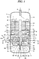
- FIG. 1 is a longitudinal sectional view illustrating an example of a lower compression type scroll compressor according to the present invention
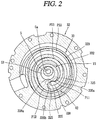
- FIG. 2 is a sectional view taken along line 'IV-IV' in FIG. 1 .
- the lower compression type scroll compressor may include a casing 1 having an inner space 1a; a motor part 2 provided at the inner space 1a of the casing 1, and configured to generate a rotational force in the form of a driving motor; a compression part 3 disposed below the motor part 2, and configured to compress a refrigerant by receiving the rotational force of the motor part 2.
- the casing 1 may include a cylindrical shell 11 which forms a hermetic container; an upper shell 12 which forms the hermetic container together by covering an upper part of the cylindrical shell 11; and a lower shell 13 which forms the hermetic container together by covering a lower part of the cylindrical shell 11, and which forms an oil storage space 1b.
- a refrigerant suction pipe 15 may be penetratingly-formed at a side surface of the cylindrical shell 11, thereby being directly communicated with a suction chamber of the compression part 3.
- a refrigerant discharge pipe 16 communicated with the inner space 1a of the casing 1 may be installed at an upper part of the upper shell 12.
- the refrigerant discharge pipe 16 may be a passage along which a refrigerant compressed by the compressor 3 and discharged to the inner space 1a of the casing 1 is discharged to the outside.
- an oil separator (not shown) for separating oil mixed with the discharged refrigerant may be connected to the refrigerant discharge pipe 16.
- a stator 21 which constitutes the motor part 2 may be installed at an upper part of the casing 1, and a rotor 22 which constitutes the motor part 2 together with the stator 21 and rotated by a reciprocal operation with the stator 21 may be rotatably installed in the stator 21.
- a plurality of slots may be formed on an inner circumferential surface of the stator 21 in a circumferential direction, thereby winding a coil 25 thereon.
- an oil collection passage 26 configured to pass oil therethrough may be formed between an outer circumferential surface of the stator 21 and an inner circumferential surface of the cylindrical shell 11, in a D-cut shape.
- a main frame 31 which constitutes the compression part 3 may be fixed to an inner circumferential surface of the casing 1, below the stator 21 with a predetermined gap therebetween.
- the main frame 31 may be coupled to the cylindrical shell 11 as an outer circumferential surface of the main frame 31 is welded or shrink-fit to an inner circumferential surface of the cylindrical shell 11.
- a ring-shaped frame side wall portion (first side wall portion) 311 may be formed at an edge of the main frame 31, and a first shaft accommodating portion 312 configured to support a main bearing portion 51 of a rotation shaft 5 to be explained later may be formed at a central part of the main frame 31.
- a first shaft accommodating hole 312a configured to rotatably insert the main bearing portion 51 of the rotation shaft 5 and support the main bearing portion 51 in a radius direction, may be penetratingly-formed at the first shaft accommodating portion 312 in an axial direction.
- a fixed scroll 32 may be installed at a bottom surface of the main frame 31, in a state where an orbiting scroll 33 eccentrically-coupled to the rotation shaft 5 is disposed between the fixed scroll 32 and the main frame 31.
- the fixed scroll 32 may be fixedly-coupled to the main frame 31, and may be fixed to the main frame 31 so as to be moveable in an axial direction.
- the fixed scroll 32 may include a fixed plate portion (hereinafter, will be referred to as a first plate portion) 321 formed in an approximate disc shape, and a scroll side wall portion (hereinafter, will be referred to as a second side wall portion) 322 formed at an edge of the first plate portion 321 and coupled to an edge of a bottom surface of the main frame 31.
- a fixed plate portion hereinafter, will be referred to as a first plate portion
- a scroll side wall portion hereinafter, will be referred to as a second side wall portion
- a fixed wrap 323, which forms a compression chamber (V) by being engaged with an orbiting wrap 332 to be explained later, may be formed on an upper surface of the first plate portion 321.
- the compression chamber (V) may be formed between the first plate portion 321 and the fixed wrap 323, and between the orbiting wrap 332 to be explained later and the second plate portion 331.
- the compression chamber (V) may be implemented as a suction chamber, an intermediate pressure chamber and a discharge chamber are consecutively formed in a moving direction of the wrap.
- the compression chamber (V) may include a first compression chamber (V1) formed between an inner side surface of the fixed wrap 323 and an outer side surface of the orbiting wrap 332, and a second compression chamber (V2) formed between an outer side surface of the fixed wrap 323 and an inner side surface of the orbiting wrap 332.
- the first compression chamber (V1) is formed between two contact points (P11, P12) generated as the inner side surface of the fixed wrap 323 and the outer side surface of the orbiting wrap 332 come in contact with each other.
- a formula ( ⁇ ⁇ 360°) is formed before a discharge operation is started.
- the second compression chamber (V2) is formed between two contact points (P21, P22) generated as the outer side surface of the fixed wrap 323 and the inner side surface of the orbiting wrap 332 come in contact with each other.
- the first compression chamber (V1) is formed such that a refrigerant is firstly sucked thereinto than the second compression chamber (V2), and such that a compression path thereof is relatively long.
- a compression ration of the first compression chamber (V1) is lower than that of the second compression chamber (V2).
- the second compression chamber (V2) is formed such that a refrigerant is later sucked thereinto than the first compression chamber (V1), and such that a compression path thereof is relatively short.
- a compression ration of the second compression chamber (V2) is higher than that of the first compression chamber (V1).
- An inlet 324 through which a refrigerant suction pipe 15 and a suction chamber are communicated with each other, is penetratingly-formed at one side of the second side wall portion 322.
- an outlet 325 communicated with a discharge chamber and through which a compressed refrigerant is discharged, may be formed at a central part of the first plate portion 321.
- the outlet 325 may be formed in one so as to be communicated with both of the first and second compression chambers (V1, V2).
- the outlet 325 may be formed in plurality so as to be communicated with the first and second compression chambers (V1, V2).
- a second shaft accommodation portion 326 configured to support a sub bearing portion 52 of the rotation shaft 5 to be explained later, may be formed at a central part of the first plate portion 321 of the fixed scroll 32.
- a second shaft accommodating hole 326a configured to support the sub bearing portion 52 in a radius direction, may be penetratingly-formed at the second shaft accommodating portion 326 in an axial direction.
- a thrust bearing portion 327 configured to support a lower end surface of the sub bearing portion 52 in an axial direction, may be formed at a lower end of the second shaft accommodation portion 326.
- the thrust bearing portion 327 may protrude from a lower end of the second shaft accommodating hole 326a in a radius direction, towards a shaft center.
- the thrust bearing portion may be formed between a bottom surface of an eccentric portion 53 of the rotation shaft 5 to be explained later, and the first plate portion 321 of the fixed scroll 32 corresponding thereto.
- a discharge cover 34 configured to accommodate a refrigerant discharged from the compression chamber (V) therein and to guide the refrigerant to a refrigerant passage to be explained later, may be coupled to a lower side of the fixed scroll 32.
- the discharge cover 34 may be formed such that an inner space thereof may accommodate therein the outlet 325 and may accommodate therein an inlet of the refrigerant passage (PG) along which a refrigerant discharged from the compression chamber (V1) is guided to the inner space 1a of the casing 1.
- the refrigerant passage (PG) may be penetratingly-formed at the second side wall portion 322 of the fixed scroll 32 and the first side wall portion 311 of the main frame 31, sequentially, at an inner side of an oil passage separation portion 8.
- the refrigerant passage (PG) may be formed so as to be consecutively recessed from an outer circumferential surface of the second side wall portion 322 and an outer circumferential surface of the first frame 311.
- the orbiting scroll 33 may be installed between the main frame 31 and the fixed scroll 32 so as to perform an orbiting motion.
- An Oldham's ring 35 for preventing a rotation of the orbiting scroll 33 may be installed between an upper surface of the orbiting scroll 33 and a bottom surface of the main frame 31 corresponding thereto, and a sealing member 36 which forms a back pressure chamber (S) may be installed at an inner side than the Oldham's ring 35.
- the back pressure chamber (S) may be implemented as a space formed by the main frame 31, the fixed scroll 32 and the orbiting scroll 33, outside the sealing member 36.
- the back pressure chamber (S) forms an intermediate pressure because a refrigerant of an intermediate pressure is filled therein as the back pressure chamber (S) is communicated with the intermediate compression chamber (V) by a back pressure hole 321a provided at the fixed scroll 32.
- a space formed at an inner side than the sealing member 36 may also serve as a back pressure chamber as oil of high pressure is filled therein.
- An orbiting plate portion (hereinafter, will be referred to as a second plate portion) 331 of the orbiting scroll 33 may be formed to have an approximate disc shape.
- the back pressure chamber (S) may be formed at an upper surface of the second plate portion 331, and the orbiting wrap 332 which forms the compression chamber by being engaged with the fixed wrap 322 may be formed at a bottom surface of the second plate portion 331.
- the eccentric portion 53 of the rotation shaft 5 to be explained later may be rotatably inserted into a central part of the second plate portion 331, such that a rotation shaft coupling portion 333 may pass therethrough in an axial direction.
- the rotation shaft coupling portion 333 may be extended from the orbiting wrap 332 so as to form an inner end of the orbiting wrap 332.
- the eccentric portion 53 of the rotation shaft 5 may be overlapped with the orbiting wrap 332 on the same plane.
- the orbiting wrap 332 may be formed to have an involute shape together with the fixed wrap 323.
- the orbiting wrap 332 may be formed to have various shapes. For instance, as shown in FIG. 2 , the orbiting wrap 332 and the fixed wrap 323 may be formed to have a shape implemented as a plurality of circles of different diameters and origin points are connected to each other, and a curved line of an outermost side may be formed as an approximate oval having a long axis and a short axis.
- a contact portion 328a may be protruded from the protrusion 328. That is, the inner end of the fixed wrap 323 may be formed to have a greater thickness than other parts. With such a configuration, the inner end of the fixed wrap 323, having the largest compressive force among other parts of the fixed wrap 323, may have an enhanced wrap intensity and may have enhanced durability.
- a concaved portion 335 engaged with the protrusion 328 of the fixed wrap 323, is formed at an outer circumference of the rotation shaft coupling portion 333 which is opposite to the inner end of the fixed wrap 323.
- a thickness increase portion 335a having its thickness increased from an inner circumferential part of the rotation shaft coupling portion 333 to an outer circumferential part thereof, is formed at one side of the concaved portion 335, at an upstream side in a direction to form the compression chambers (V). This may enhance a compression ratio of the first compression chamber (V1) by shortening a length of the first compression chamber (V1) prior to a discharge operation.
- a circular arc surface 335b having a circular arc shape is formed at another side of the concaved portion 335.
- a diameter of the circular arc surface 335b is determined by a thickness of the inner end of the fixed wrap 323 and an orbiting radius of the orbiting wrap 332. If the thickness of the inner end of the fixed wrap 323, the diameter of the circular arc surface 335b is increased. This may allow the orbiting wrap around the circular arc surface 335b to have an increased thickness and thus to obtain durability. Further, since a compression path becomes longer, a compression ratio of the second compression chamber (V2) may be increased in correspondence thereto.
- the rotation shaft 5 may be supported in a radius direction as an upper part thereof is forcibly-coupled to a central part of the rotor 22, and as a lower part thereof is coupled to the compression part 3.
- the rotation shaft 5 transmits a rotational force of the motor part 2 to the orbiting scroll 33 of the compression part 3.
- the orbiting scroll 33 eccentrically-coupled to the rotation shaft 5 performs an orbiting motion with respect to the fixed scroll 32.
- a main bearing portion 51 supported in a radius direction by being inserted into the first shaft accommodating hole 312a of the main frame 31, may be formed at a lower part of the rotation shaft 5.
- the sub bearing portion 52 supported in a radius direction by being inserted into the second shaft accommodating hole 326a of the fixed scroll 32, may be formed below the main bearing portion 51.
- the eccentric portion 53 inserted into the rotation shaft coupling portion 333 of the orbiting scroll 33, may be formed between the main bearing portion 51 and the sub bearing portion 52.
- the main bearing portion 51 and the sub bearing portion 52 may be formed to be concentric with each other, and the eccentric portion 53 may be formed to be eccentric from the main bearing portion 51 or the sub bearing portion 52 in a radius direction.
- the sub bearing portion 52 may be formed to be eccentric from the main bearing portion 51.
- An outer diameter of the eccentric portion 53 may be preferably formed to be smaller than that of the main bearing portion 51 but to be larger than that of the sub bearing portion 52, such that the rotation shaft 5 may be easily coupled to the eccentric portion 53 through the shaft accommodating holes 312a, 326a, and the rotation shaft coupling portion 333.
- the rotation shaft 5 may be coupled to the eccentric portion 53, without the configuration that the outer diameter of the eccentric portion 53 is larger than that of the sub bearing portion 52.
- An oil supply passage 5a along which oil is supplied to the bearing portions and the eccentric portion, may be formed in the rotation shaft 5.
- the oil supply passage 5a may be formed in a chamfering manner from a lower end of the rotation shaft 5 to a lower end of the stator 21 or to an intermediate height of the stator 21, or to a height higher than an upper end of the main bearing portion 51.
- An oil feeder 6, configured to pump oil contained in the oil storage space 1b, may be coupled to a lower end of the rotation shaft 5, i.e., a lower end of the sub bearing portion 52.
- the oil feeder 6 may include an oil supply pipe 61 insertion-coupled to the oil supply passage 5a of the rotation shaft 5, and an oil sucking member 62 (e.g., propeller) inserted into the oil supply pipe 61 and configured to suck oil.
- the oil supply pipe 61 may be installed to be immersed in the oil storage space 1b via a though hole 341 of the discharge cover 34.
- An oil supply hole and/or an oil supply groove configured to supply oil sucked through the oil supply passage to an outer circumferential surface of each of the respective bearing portions and the eccentric portion, may be formed at the respective bearing portions and the eccentric portion, or at a position between the respective bearing portions.
- oil sucked toward an upper end of the main bearing portion 51 along the oil supply passage 5a of the rotation shaft 5, an oil supply hole (not shown) and an oil supply groove (not shown) flows out of bearing surfaces from an upper end of the first shaft accommodating portion 312 of the main frame 31. Then, the oil flows down onto an upper surface of the main frame 31, along the first shaft accommodating portion 312.
- the oil is collected in the oil storage space 1b, through an oil passage (PO) consecutively formed on an outer circumferential surface of the main frame 31 (or through a groove communicated from the upper surface of the main frame 31 to the outer circumferential surface of the main frame 31) and an outer circumferential surface of the fixed scroll 32.
- PO oil passage
- oil discharged to the inner space 1a of the casing 1 from the compression chamber (V) together with a refrigerant, is separated from the refrigerant at an upper space of the casing 1. Then, the oil is collected in the oil storage space 1b, through a passage formed on an outer circumferential surface of the motor part 2, and through the oil passage (PO) formed on an outer circumferential surface of the compression part 3.
- the lower compression type scroll compressor according to the present invention is operated as follows.
- the rotor 21 and the rotation shaft 5 are rotated as a rotational force is generated.
- the orbiting scroll 33 eccentrically-coupled to the rotation shaft 5 performs an orbiting motion by the Oldham's ring 35.
- the refrigerant supplied from the outside of the casing 1 through the refrigerant suction pipe 15 is introduced into the compression chambers (V), and the refrigerant is compressed as a volume of the compression chambers (V) is reduced by the orbiting motion of the orbiting scroll 33. Then, the compressed refrigerant is discharged to an inner space of the discharge cover 34 through the outlet 325.
- the refrigerant discharged to the inner space of the discharge cover 34 circulates at the inner space of the discharge cover 34, thereby having its noise reduced. Then, the refrigerant moves to a space between the main frame 31 and the stator 21, and moves to an upper space of the motor part 2 through a gap between the stator 21 and the rotor 22.
- the refrigerant has oil separated therefrom at the upper space of the motor part 2, and then is discharged to the outside of the casing 1 through the refrigerant discharge pipe 16.
- the oil is collected in the oil storage space, a lower space of the casing 1, through a flow path between an inner circumferential surface of the casing 1 and the stator 21, and through a flow path between the inner circumferential surface of the casing 1 and an outer circumferential surface of the compression part 3.
- Such processes are repeatedly performed.
- the compression chamber (V) formed between the fixed scroll 32 and the orbiting scroll 33 has a suction chamber at an edge region, and has a discharge chamber at a central region on the basis of the orbiting scroll 33.
- the fixed scroll 32 and the orbiting scroll 33 have a highest temperature at the central region, and have a lowest temperature at the edge region.
- a suction refrigerant temperature is about 18J at the suction chamber
- a discharge refrigerant temperature is about 80 ⁇ at the discharge chamber. This may cause a temperature around the suction chamber to be much lower than a temperature around the discharge chamber.
- a high temperature refrigerant discharged from the discharge chamber spreads to an entire region of an inner space of the discharge cover 34, thereby contacting a rear surface of the first plate portion 321 of the fixed scroll 32 which forms the inner space of the discharge cover 34.
- the first plate portion 321 of the fixed scroll 32 has a tendency to expand to an edge region by receiving heat from the high temperature refrigerant.
- the fixed wrap 323, far from the inner space of the discharge cover 34 has a smaller tendency to expand than the first plate portion 321. Due to such a thermal transformation difference, the fixed scroll 32 is transformed in a shape to contract in a wrap direction.
- the fixed wrap near the suction chamber is much influenced by a a suction refrigerant temperature than the fixed wrap at another region, thereby having a tendency to be contracted. This may cause an end of the fixed wrap near the suction chamber to be more contracted (more transformed) than the fixed wrap which is positioned at an opposite side to the suction chamber.
- FIG. 3 is a planar view illustrating a thermally-deformed state of a fixed scroll in the scroll compressor of FIG. 1 .
- FIG. 4 is a frontal schematic view of the fixed scroll of FIG. 3 .
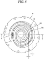
- FIG. 5 is a sectional view illustrating a partial interference between a fixed wrap and an orbiting wrap, in a coupled state of an orbiting scroll to the fixed scroll of FIG. 3 .
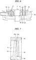
- FIG. 6 is a sectional view taken along line 'V-V' in FIG. 5 .
- FIG. 7 is a sectional view which illustrates part C" of FIG. 6 in an enlarged manner.
- the first plate portion 321 of the fixed scroll 32 is bent towards an upper side, i.e., an opposite direction to a contact surface with the discharge cover 34.
- a region (A) near the suction chamber (Vs) is more bent than an opposite region (crank angle of 180°) (B) by a predetermined angle ( ⁇ 1- ⁇ 2).
- an offset portion which forms an offset section, near the suction chamber of the fixed wrap and the suction chamber of the orbiting wrap corresponding thereto.
- FIG. 8 is a planar view illustrating a coupled state of the fixed scroll and the orbiting scroll each having an offset portion, in a concentric state of the fixed scroll and the orbiting scroll in the scroll compressor according to the present invention.
- FIG. 9 is a planar view illustrating an offset portion according to this embodiment in an enlarged manner.
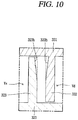
- FIG. 10 is a sectional view taken along line 'VI-VI' in FIG. 9 .
- an offset portion may be formed at each of the fixed wrap 323 and the orbiting wrap 332.
- the offset portion formed at the fixed wrap 323 is called 'first offset portion'
- the offset portion formed at the orbiting wrap 332 is called 'second offset portion'.
- the first offset portion 323b may be formed at a region including at least part of a section of the fixed wrap 323 which forms the suction chamber (Vs)
- the second offset portion 332b may be formed at a region including at least part of a section of the orbiting wrap 332 which forms the suction chamber (Vs).
- the first offset portion 323b may be formed within a range of ⁇ 30° from a center (O) of the fixed scroll, on the basis of a suction completion point of the fixed wrap 323.
- the second offset portion 332b may be formed at the orbiting wrap 332 within a range corresponding to the first offset portion 323b of the fixed wrap 323.
- the suction completion point means a region where suction at the first compression chamber (V1) formed by an inner side surface of the fixed wrap 323 is completed, i.e., a time point when a suction end of the orbiting wrap 332 contacts an inner side surface of the fixed wrap 323.
- a crank angle is 0° (zero).
- crank angle When the crank angle is -30°, an angle is formed between a virtual line which connects a center (O) of the fixed scroll 32 with the suction completion point, and a farthest side wall surface of the inlet 324 (i.e., a farthest point in an opposite direction to a compression direction).
- a proper offset amount of the offset portion (Os) is a value which satisfies [a thermal expansion coefficient ( ⁇ ) of a material of the scroll ⁇ a distance (L) from a center of the scroll to the offset portion (L) ⁇ a temperature difference ( ⁇ T) between a suction refrigerant and a discharge refrigerant].
- a refrigerant suction temperature is within a range of -40 ⁇ 30 ⁇
- a refrigerant discharge temperature is within a range of 35 ⁇ 140 ⁇
- the distance (L) is 32mm
- the thermal expansion coefficient ( ⁇ ) is 1 ⁇ 10-5/ ⁇
- the temperature difference ( ⁇ T) is within a range of 5 ⁇ ⁇ 180 ⁇ .
- the proper offset amount is about 2 ⁇ m.
- the proper offset amount is about 58 ⁇ m. Accordingly, the proper offset amount ( ⁇ ) is within a range of 2 ⁇ m ⁇ ⁇ ⁇ 58 ⁇ m.
- a substantial offset amount is smaller than the proper offset amount, interference between the fixed wrap 323 and the orbiting wrap 332 may occur near the suction chamber. In this case, at an opposite side to the suction chamber, a gap (t) between the fixed wrap 323 and the orbiting wrap 332 may occur as the orbiting scroll 33 is pushed. On the other hand, if a substantial offset amount is larger than the proper offset amount, a gap between the fixed wrap 323 and the orbiting wrap 332 may occur near the suction chamber. In this case, at an opposite side to the suction chamber, a frictional loss and abrasion may occur due to interference between the fixed wrap 323 and the orbiting wrap 332.
- the first and second offset portions 323b, 332b may be formed in a distributed manner with a proper ratio such that the sum of the first and second offset portions 323b, 332b may satisfy the proper offset amount.
- a thickness of the fixed wrap 323 or the orbiting wrap 332 is prevented from being excessively reduced at the first or second offset portion 323b, 332b, damage of the fixed wrap or the orbiting wrap may be prevented when the scroll compressor is driven with a high compression ratio.
- the offset portion 323b may be formed only at the fixed wrap 323.
- the offset portion 332b may be formed only at the orbiting wrap 332.
- a wrap thickness of the fixed wrap or the orbiting wrap is reduced, resulting in lowering a reliability when the scroll compressor is driven with a high compression ratio.
- each of the first and second offset portions 323b, 332b may be formed in a curved shape, such that an offset amount may be increased towards a central region from two ends thereof.
- the central region of the offset portion is positioned on a virtual line (CL) which connects a center (O) of the fixed scroll 32 (or the orbiting scroll) with the suction completion point, which receives a stress the most with a largest transformation amount when the fixed scroll 32 is transformed.
- CL virtual line
- a section (or a region) of the fixed wrap 323, which is to be transformed the most is offset the most, thereby minimizing an interference amount between the fixed wrap 323 and the orbiting wrap 332.
- each of the first and second offset portions 323b, 332b may be formed as a curved surface having one or more curvature radiuses (R2).
- the curvature radius (R2) of the first offset portion 323b may be smaller than a curvature radius (R1) of the fixed wrap 323 at a corresponding position.
- the second offset portion of the orbiting wrap may be formed vice versa.
- each offset portion may be formed in a straight shape such that its depth may be constant. In this case, two ends of the offset portion may be formed as a curved surface for slidable contact between the wraps.
- each of the first and second offset portions 323b, 332b may be formed at an entire section of the fixed wrap 323 or the orbiting wrap 332, in a wrap moving direction.
- each of the first and second offset portions 323b, 332b may be formed to have a uniform depth in a wrap moving direction.
- each offset portion is preferably formed to have a depth increased towards an edge region from a central region. If each offset portion is formed to have a uniform depth, an offset amount is relatively large at a region having a small transformation amount, resulting in a gap between the two wraps. On the other hand, if an offset amount is relatively small at a region having a large transformation amount, resulting in interference between the two wraps. Thus, an offset amount is largest at a region having a largest transformation amount, and is smallest at a region having a smallest transformation amount. Preferably, the offset amount is proportionally reduced towards a region having a small offset amount from a region having a large offset amount.
- the orbiting scroll may be prevented from being pushed in a radius direction. This may restrict or minimize occurrence of a gap between the fixed wrap and the orbiting wrap, thereby enhancing compression efficiency.
- the first offset portion 323b may be inclined such that a wrap thickness may be reduced from a wrap root (or a wrap intermediate region) of the fixed wrap 323 contacting the first plate portion 321 to a wrap end.
- the second offset portion 332b may be inclined such that a wrap thickness may be reduced from a wrap end to a wrap root of the orbiting wrap.
- the first and second offset portions 323b, 332b are configured to prevent interference between the fixed wrap 323 near the suction chamber (Vs) and the orbiting wrap 332, due to bending towards a central region. Therefore, it is preferable to form the first offset portion 323b on an inner side surface of the fixed wrap 323, and to form the second offset portion 332b on an outer side surface of the orbiting wrap 332.
- the envelope means a moving path of the compression chamber.
- formed is a shape of an inner side surface of the fixed wrap and an outer side surface of the orbiting wrap, or a shape of an outer side surface of the fixed wrap and an inner side surface of the orbiting wrap.
- FIG. 11 is a schematic view illustrating a distance between an inner side surface of the fixed wrap and an outer side surface of the orbiting wrap when there is provided no offset portion
- FIG. 12 is a schematic view illustrating a distance between an inner side surface of the fixed wrap and an outer side surface of the orbiting wrap when there is provided an offset portion.
- a distance ( ⁇ ) between the two wraps obtained by adding a distance ( ⁇ 1) from the envelope (Lp) to an inner side surface of the fixed wrap 323, to a distance (52) from the envelope (Lp) to an outer side surface of the orbiting wrap 332, is the same as an orbiting radius (r).
- a distance ( ⁇ 1) from the envelope (Lp) to an inner side surface of the fixed wrap 323, to a distance (52) from the envelope (Lp) to an outer side surface of the orbiting wrap 332 is the same as an orbiting radius (r).
- a distance ( ⁇ ') between the two wraps obtained by adding a distance ( ⁇ 1') from the envelope (Lp) to an inner side surface of the fixed wrap 323, to a distance ( ⁇ 2') from the envelope (Lp) to an outer side surface of the orbiting wrap 332, is larger than the orbiting radius (r).
- r the orbiting radius
- a transformation amount of the fixed wrap 323 may be different from that of the orbiting wrap 332.
- offset amounts of the first and second offset portions 323b, 332b may be preferably different from each other within a range which satisfies a proper offset amount.
- an offset amount of the first offset portion 323b may be preferably larger than that of the second offset portion 332b. That is, in this embodiment, as a wrap end of the fixed wrap 323 and a wrap end of the orbiting wrap 332 are bent towards a central region, an edge of an inner side surface of the fixed wrap 323 may be interfered with a wrap root of the orbiting wrap 332. Since a wrap root of the fixed wrap 323 does not contact a wrap end of the orbiting wrap 332 (more precisely, a side surface of a wrap end), the first offset portion 323b may be formed only at an edge of an inner side surface of the fixed wrap 323.
- the fixed wrap 323 may maintain its thickness at a root thereof, resulting in enhancing a reliability even when the scroll compressor is driven with a high compression ratio.
- the second offset portion 332b should be formed up to an end of a wrap root, i. e, a region where the wrap and the plate portion meet, or a neighboring region.
- an offset amount of the first offset portion 323b may be preferably larger than that of the second offset portion 332b.
- a wrap thickness of the fixed wrap is reduced at a section having the largest stress. This may prevent interference between the fixed wrap and the orbiting wrap at a corresponding section to the maximum. This may prevent refrigerant leakage through a gap formed between the fixed wrap and the orbiting wrap at an opposite side to a suction side, due to a partial interference therebetween.
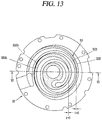
- FIG. 13 is a planar view illustrating a coupled state of the fixed scroll and the orbiting scroll each having the offset portion according to the present invention
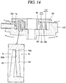
- FIG. 14 is a sectional view taken along line 'VII-VII' in FIG. 13 .
- an inlet 324 is formed on the left side of the drawing
- an end of the fixed wrap 323 is much bent to the right side of the drawing at a section of the fixed wrap 323 adjacent to the inlet 324. This may cause the end of the fixed wrap 323 to be interfered with a root of the orbiting wrap 332.
- first and second offset portions 323b, 332b are formed on a right side surface of the fixed wrap 323 and a left side surface of the orbiting wrap 332, respectively, in reverse shapes, interference between the fixed wrap 323 and the orbiting wrap 332 may be prevented. This may prevent the orbiting scroll 33 from being moved to the right side of the drawing. As a result, the fixed wrap 323 and the orbiting wrap 332 do not have a gap therebetween on the right side of the drawing. Even if the fixed wrap 323 and the orbiting wrap 332 are spaced from each other, a spacing distance therebetween may be minimized and thus leakage of a compressed refrigerant may be minimized.
- first offset portion or both of the first and second offset portions are formed to be inclined from a wrap root to a wrap end.
- the first and second offset portions may be respectively formed at the wrap end and the wrap root, with a stair-step, with consideration of a processability.
- the first offset portion 323b may be formed at an edge of an inner end of the fixed wrap 323, in a stair-stepped shape.
- the second offset portion 332b may be formed at a wrap root outside the orbiting wrap 332, in the form of a groove with a stair-step.
- a proper offset amount is the same as that of the aforementioned embodiment, and a basic configuration and effects are similar to those of the aforementioned embodiment. Thus, detailed explanations thereof will be omitted.
- the fixed wrap 323 may be easily processed.
- the orbiting wrap 332 may have an enhanced processability, since a processing of the second offset portion 332b is easier than the aforementioned inclined processing.
- a wrap thickness of the fixed wrap 323 may be generally reduced, resulting in a low intensity of the fixed wrap 323.
- the fixed wrap 323 may maintain its wrap thickness at a wrap root. This may allow the fixed wrap 323 to maintain its intensity, resulting in obtaining a reliability.
- each of the fixed wrap and the orbiting wrap is formed such that a sectional area at a wrap end is different from a sectional area at a wrap root.
- an offset portion is formed such that a sectional area at a wrap end is the same as a sectional area at a wrap root.
- first offset portion 323b is formed on an inner side surface of the fixed wrap 323, and the second offset portion 332b is formed on an outer side surface of the orbiting wrap 332.
- each of the first and second offset portions 323b, 332b may be formed such that a sectional area at a wrap end may be the same as a sectional area at a wrap root.
- a sectional area of a wrap end may be the same as a sectional area of a wrap root.
- first and second offset portions 323b, 332b may be easily processed as they are processed in a direction perpendicular to the wraps.
- first offset portion 323b of the fixed wrap 323 may be formed with a stair-step, by cutting only an edge of a wrap end.
- the invention further relates to the following numbered items:
Landscapes
- Engineering & Computer Science (AREA)
- Mechanical Engineering (AREA)
- General Engineering & Computer Science (AREA)
- Rotary Pumps (AREA)
- Applications Or Details Of Rotary Compressors (AREA)
Abstract
Description
- This specification relates to a scroll compressor.
- Generally, a scroll compressor is being widely used at an air conditioner, etc., in order to compress a refrigerant, owing to its advantages that a compression ratio is relatively higher than that of other types of compressors, and a stable torque is obtainable since processes for sucking, compressing and discharging a refrigerant are smoothly performed.
- A behavior characteristic of the scroll compressor is determined by a non-orbiting wrap (hereinafter, will be referred to as a fixed wrap) of a non-orbiting scroll (hereinafter, will be referred to as a fixed scroll) and an orbiting wrap of an orbiting scroll. The fixed wrap and the orbiting wrap may have any shape, but they generally have a shape of an involute curve for easy processing. The involute curve means a curved line corresponding to a moving path drawn by the end of a thread when the thread wound around a basic circle having any radius is unwound. In case of using such an involute curve, the fixed wrap and the orbiting wrap stably perform a relative motion since they have a constant thickness, thereby forming a compression chamber to compress a refrigerant.
- As the compression chamber of the scroll compressor has a volume decreased towards an inner side from an outer side, a suction chamber is formed at the outer side and a discharge chamber is formed at the inner side. A refrigerant sucked into the suction chamber has a temperature of about 18°C, and a refrigerant discharged from the discharge chamber has a temperature of about 80°C. However, the orbiting scroll is not greatly influenced by a refrigerant discharge temperature, since a rear surface thereof is positioned between the orbiting scroll and the fixed scroll in a supported state by a main frame. On the other hand, the fixed scroll is exposed to a refrigerant discharge temperature as a plate portion which forms a rear surface thereof is coupled to an inner space of a casing or a discharge cover or a high and low pressure separation plate.
- As the rear surface of the fixed scroll is exposed to a refrigerant discharge temperature, the plate portion of the fixed scroll is entirely influenced by the refrigerant discharge temperature to be thermally-expanded. On the other hand, a fixed wrap, provided on one side surface of the plate portion of the fixed scroll and forming the compression chamber, is not entirely influenced by a refrigerant discharge temperature. More specifically, a part of the fixed wrap near a suction chamber is influenced by a suction temperature, a part of the fixed wrap near an intermediate pressure chamber is influenced by an intermediate compression temperature, and a part of the fixed wrap near a discharge chamber is influenced by a discharge temperature. That is, the fixed wrap has a different thermal expansion rate according to a region. As the plate portion of the fixed scroll is more thermally-transformed than the fixed wrap, the fixed wrap is transformed in a contracted shape.
- Especially, since the fixed wrap near the suction chamber directly contacts a cold suction refrigerant having a temperature of about 18°C, the fixed wrap near the suction chamber is more transformed than other regions, because it has a tendency to be contracted towards a central region. This may cause an orbiting wrap contacting the fixed wrap formed near the suction chamber, to be pushed by the bent fixed wrap. As a result, the orbiting wrap having a crank angle of 180° at an opposite side is spaced from the fixed wrap, resulting in a compression loss.
- Further, as a specific region of the fixed wrap is more thermally-transformed than other regions, the fixed wrap and the orbiting wrap may excessively contact each other. This may increase a frictional loss or abrasion between the fixed scroll and the orbiting scroll.
- Therefore, an aspect of the detailed description is to provide a scroll compressor capable of preventing a compression loss due to leakage of a compressed refrigerant, the compression loss occurring as a fixed wrap and an orbiting wrap are spaced from each other.
- Another aspect of the detailed description is to provide a scroll compressor capable of preventing an orbiting scroll from being pushed by preventing a thermal transformation of a specific part of a fixed wrap.
- Another aspect of the detailed description is to provide a scroll compressor capable of preventing a frictional loss or abrasion between a fixed scroll and an orbiting scroll, due to an excessive contact between a fixed wrap and an orbiting wrap at a specific part.
- To achieve these and other advantages and in accordance with the purpose of this specification, as embodied and broadly described herein, there is provided a scroll compressor, including: a fixed scroll having a fixed wrap, having an inlet at an edge region thereof, and having an outlet at a central region thereof; and an orbiting scroll having an orbiting wrap to form a compression chamber by being engaged with the fixed wrap, wherein an offset portion is formed to reduce a wrap thickness of the fixed wrap near the inlet.
- According to another aspect of the present invention, there is provided a scroll compressor, including: a fixed scroll having a fixed wrap, having an inlet at an edge region thereof, and having an outlet at a central region thereof; and an orbiting scroll having an orbiting wrap to form a compression chamber by being engaged with the fixed wrap, wherein at least part of a wrap thickness decrease region of the fixed wrap or the orbiting wrap is included within a range, from a point where the inlet starts to a suction completion point on the basis of a center of the fixed scroll, the suction completion point formed on an inner side surface of the fixed wrap and where suction at the compression chamber is completed.
- According to another aspect of the present invention, there is provided a scroll compressor, including: a fixed scroll having a fixed wrap, having an inlet at an edge region thereof, and having an outlet at a central region thereof; and an orbiting scroll having an orbiting wrap to form a compression chamber by being engaged with the fixed wrap, wherein an offset portion having a predetermined depth in a radius direction is formed on an inner side surface of the fixed wrap which faces the inlet.
- According to another aspect of the present invention, there is provided a scroll compressor, including: a fixed scroll having a fixed wrap, having an inlet at an edge region thereof, and having an outlet at a central region thereof; and an orbiting scroll having an orbiting wrap to form a compression chamber by being engaged with the fixed wrap, wherein an edge of an inner side surface of the fixed wrap near the inlet is chamfered.
- According to another aspect of the present invention, there is provided a scroll compressor, including: a fixed scroll having a fixed wrap, having an inlet at an edge region thereof, and having an outlet at a central region thereof; and an orbiting scroll having an orbiting wrap to form a compression chamber by being engaged with the fixed wrap, wherein an inner side surface of the fixed wrap near the inlet is formed as a curved surface having a smaller curvature radius than other parts.
- According to another aspect of the present invention, there is provided a scroll compressor, including: an orbiting scroll having an orbiting wrap, and which performs an orbiting motion; and a fixed scroll having a fixed wrap to form a compression chamber of a suction chamber, an intermediate pressure chamber and a discharge chamber, by being engaged with the orbiting wrap, wherein in a state where the orbiting scroll and the fixed scroll are concentric with each other, when a distance between the two wraps is defined as a an orbiting radius, there exists an offset section having an interval larger than the orbiting radius, between a side surface of the orbiting wrap and a side surface of the fixed wrap which faces the side surface of the orbiting wrap.
- At least part of the offset section may be overlapped with a section which forms the suction chamber.
- A wrap thickness within the offset section may be smaller than a wrap thickness out of the offset section.
- According to another aspect of the present invention, there is provided a scroll compressor, including: an orbiting scroll having an orbiting wrap, and which performs an orbiting motion; and a fixed scroll having a fixed wrap to form a compression chamber of a suction chamber, an intermediate pressure chamber and a discharge chamber, by being engaged with the orbiting wrap, wherein an offset portion is formed on a side surface of at least one of the fixed wrap and the orbiting wrap so as to have a distance between the two wraps greater than an orbiting radius defined as a distance between the two wraps in a concentric state between the orbiting scroll and the fixed scroll.
- The offset portion may be formed on one side surface of the fixed wrap, opposite to another side surface of the fixed wrap which forms the suction chamber.
- The offset portion may be formed such that at least part thereof may be included between two virtual lines which connect a center of the fixed scroll with two ends of a section which forms the suction chamber.
- When one side surface of the fixed wrap which is towards a center of the fixed scroll is defined as an inner side surface and another side surface opposite to the one side surface is defined as an outer side surface, the offset portion may be formed on the inner side surface of the fixed wrap.
- When one side surface of the orbiting wrap which is towards a center of the orbiting scroll is defined as an inner side surface and another side surface opposite to the one side surface is defined as an outer side surface, the offset portion may be formed on the outer side surface of the orbiting wrap.
- The offset portion may be formed such that its depth may be increased towards a central region from two ends thereof in a wrap moving direction.
- The offset portion may be formed as a curved surface having one or more curvature radiuses. And the curvature radius of the offset portion may be smaller than a curvature radius of the wrap.
- The fixed wrap at a section where the offset portion is formed, may have a sectional area decreased towards a wrap end from a wrap root or a region near the wrap root.
- The orbiting wrap at a section where the offset portion is formed, may have a sectional area increased towards a wrap end from a wrap root.
- The fixed wrap at a section where the offset portion is formed, may have a stair-step at an edge of a wrap end thereof.
- The orbiting wrap at a section where the offset portion is formed, may have a groove having a predetermined depth near a wrap root.
- The fixed wrap or the orbiting wrap at a section where the offset portion is formed, may be formed to have the same sectional area from a wrap root to a wrap end.
- An offset amount of the offset portion may be calculated by a formula, [a thermal expansion coefficient of the scroll × a distance from a center of the scroll to a side surface of a corresponding wrap × a temperature difference between a suction refrigerant and a discharge refrigerant].
- According to another aspect of the present invention, there is provided a scroll compressor, including: a casing; a driving motor provided at an inner space of the casing; a rotation shaft coupled to a rotor of the driving motor, and rotated together with the rotor; a frame installed below the driving motor; a fixed scroll provided below the frame, having an inlet and an outlet, and having a fixed wrap; an orbiting scroll provided between the frame and the fixed scroll, and having an orbiting wrap which forms a compression chamber of a suction chamber, an intermediate pressure chamber and a discharge chamber, by being engaged with the fixed wrap, the orbiting scroll having a rotation shaft coupling portion for coupling the rotation shaft in a penetrating manner; and a discharge cover coupled to a lower side of the fixed scroll, and configured to accommodate the outlet therein in order to guide a refrigerant discharged through the outlet to the inner space of the casing, wherein in a state where the orbiting scroll and the fixed scroll are concentric with each other, when a distance between the two wraps is defined as a an orbiting radius, there exists an offset section having an interval larger than the orbiting radius, between a side surface of the orbiting wrap and a side surface of the fixed wrap which faces the side surface of the orbiting wrap, and wherein at least part of the offset section is overlapped with a section which forms the suction chamber.
- The offset section may be formed such that at least part thereof may be positioned within a range of ±30° (crank angle), on the basis of a suction completion point formed on an inner side surface of the fixed wrap and where suction at the compression chamber is completed.
- An offset amount at the offset section may be calculated by a formula, [a thermal expansion coefficient of the scroll × a distance from a center of the scroll to a side surface of a corresponding wrap × a temperature difference between a suction refrigerant and a discharge refrigerant].
- The compression chamber may include a first compression chamber formed on an inner side surface of the fixed wrap, and a second compression chamber formed on an outer side surface of the fixed wrap. The first compression chamber may be defined between two contact points P11 and P12 generated as the inner side surface of the fixed wrap contacts an outer side surface of the orbiting wrap. And a formula of 0° < α < 360° may be formed, wherein α is an angle defined by two lines which connect a center O of the eccentric portion to the two contact points P1 and P2, respectively.
- In the scroll compressor of the present invention, since the offset portion concaved by a predetermined depth is formed on a side surface of the fixed wrap and/or the orbiting wrap at a section which forms the suction chamber, interference between the fixed wrap and the orbiting wrap at a specific part may be prevented. This may prevent leakage of a compressed refrigerant, occurring at an opposite side (180°) to the suction chamber to the suction chamber as the fixed wrap and the orbiting wrap are spaced from each other.
- Further, since interference between the fixed wrap and the orbiting wrap at a specific part due to a thermal transformation of the fixed wrap is prevented, an excessive contact between the fixed wrap and the orbiting wrap at the specific part may be prevented. This may reduce a frictional loss, or abrasion of the fixed scroll or the orbiting scroll, thereby enhancing a reliability of the scroll compressor.
- Further scope of applicability of the present application will become more apparent from the detailed description given hereinafter. However, it should be understood that the detailed description and specific examples, while indicating preferred embodiments of the invention, are given by way of illustration only, since various changes and modifications within the spirit and scope of the invention will become apparent to those skilled in the art from the detailed description.
- The accompanying drawings, which are included to provide a further understanding of the invention and are incorporated in and constitute a part of this specification, illustrate exemplary embodiments and together with the description serve to explain the principles of the invention.
- In the drawings:
-
FIG. 1 is a longitudinal sectional view illustrating an example of a lower compression type scroll compressor according to the present invention; -
FIG. 2 is a sectional view taken along line 'IV-IV' inFIG. 1 ; -
FIG. 3 is a planar view illustrating a thermally-deformed state of a fixed scroll in the scroll compressor ofFIG. 1 ; -
FIG. 4 is a frontal schematic view of the fixed scroll ofFIG. 3 ; -
FIG. 5 is a sectional view illustrating a partial interference between a fixed wrap and an orbiting wrap, in a coupled state of an orbiting scroll to the fixed scroll ofFIG. 3 ; -
FIG. 6 is a sectional view taken along line 'V-V' inFIG. 5 ; -
FIG. 7 is a sectional view which illustrates part C" ofFIG. 6 in an enlarged manner; -
FIG. 8 is a planar view illustrating a coupled state of a fixed scroll and an orbiting scroll each having an offset portion, in a concentric state of the fixed scroll and the orbiting scroll in a scroll compressor according to the present invention; -
FIG. 9 is a planar view illustrating an offset portion according to this embodiment in an enlarged manner; -
FIG. 10 is a sectional view taken along line 'VI-VI' inFIG. 9 ; -
FIG. 11 is a schematic view illustrating a distance between an inner side surface of a fixed wrap and an outer side surface of an orbiting wrap when there is provided no offset portion; -
FIG. 12 is a schematic view illustrating a distance between an inner side surface of a fixed wrap and an outer side surface of an orbiting wrap when there is provided an offset portion; -
FIG. 13 is a planar view illustrating a coupled state of a fixed scroll and an orbiting scroll each having an offset portion according to the present invention; -
FIG. 14 is a sectional view taken along line 'VII-VII' inFIG. 13 ; and -
FIGS. 15 and 16 are longitudinal sectional views illustrating offset portions according to other embodiments of the present invention. - Hereinafter, a scroll compressor according to the present invention will be explained in more detail with reference to the attached drawings. For reference, the scroll compressor according to the present invention is to prevent interference between a fixed wrap and an orbiting wrap at a region near a suction chamber, due to a non-uniform thermal transformation of a fixed scroll, by forming a wrap thickness of the fixed wrap near the suction chamber to be small. Thus, the present invention may be applied to any type of scroll compressor having a fixed wrap and an orbiting wrap. However, for convenience, will be explained a lower compression type scroll compressor where a compression part is disposed below a motor part, more specifically, a scroll compressor where a rotation shaft is overlapped with an orbiting wrap on the same plane. Such a scroll compressor is appropriate to be applied to a refrigerating cycle of a high temperature and a high compression ratio.
-
FIG. 1 is a longitudinal sectional view illustrating an example of a lower compression type scroll compressor according to the present invention, andFIG. 2 is a sectional view taken along line 'IV-IV' inFIG. 1 . - Referring to
FIG. 1 , the lower compression type scroll compressor according to this embodiment of the present invention may include a casing 1 having an inner space 1a; amotor part 2 provided at the inner space 1a of the casing 1, and configured to generate a rotational force in the form of a driving motor; acompression part 3 disposed below themotor part 2, and configured to compress a refrigerant by receiving the rotational force of themotor part 2. - The casing 1 may include a
cylindrical shell 11 which forms a hermetic container; anupper shell 12 which forms the hermetic container together by covering an upper part of thecylindrical shell 11; and alower shell 13 which forms the hermetic container together by covering a lower part of thecylindrical shell 11, and which forms anoil storage space 1b. - A
refrigerant suction pipe 15 may be penetratingly-formed at a side surface of thecylindrical shell 11, thereby being directly communicated with a suction chamber of thecompression part 3. And arefrigerant discharge pipe 16 communicated with the inner space 1a of the casing 1 may be installed at an upper part of theupper shell 12. Therefrigerant discharge pipe 16 may be a passage along which a refrigerant compressed by thecompressor 3 and discharged to the inner space 1a of the casing 1 is discharged to the outside. And an oil separator (not shown) for separating oil mixed with the discharged refrigerant may be connected to therefrigerant discharge pipe 16. - A
stator 21 which constitutes themotor part 2 may be installed at an upper part of the casing 1, and arotor 22 which constitutes themotor part 2 together with thestator 21 and rotated by a reciprocal operation with thestator 21 may be rotatably installed in thestator 21. - A plurality of slots (not shown) may be formed on an inner circumferential surface of the
stator 21 in a circumferential direction, thereby winding acoil 25 thereon. And an oil collection passage 26 configured to pass oil therethrough may be formed between an outer circumferential surface of thestator 21 and an inner circumferential surface of thecylindrical shell 11, in a D-cut shape. - A
main frame 31 which constitutes thecompression part 3 may be fixed to an inner circumferential surface of the casing 1, below thestator 21 with a predetermined gap therebetween. Themain frame 31 may be coupled to thecylindrical shell 11 as an outer circumferential surface of themain frame 31 is welded or shrink-fit to an inner circumferential surface of thecylindrical shell 11. - A ring-shaped frame side wall portion (first side wall portion) 311 may be formed at an edge of the
main frame 31, and a firstshaft accommodating portion 312 configured to support amain bearing portion 51 of arotation shaft 5 to be explained later may be formed at a central part of themain frame 31. A firstshaft accommodating hole 312a, configured to rotatably insert themain bearing portion 51 of therotation shaft 5 and support themain bearing portion 51 in a radius direction, may be penetratingly-formed at the firstshaft accommodating portion 312 in an axial direction. - A fixed
scroll 32 may be installed at a bottom surface of themain frame 31, in a state where anorbiting scroll 33 eccentrically-coupled to therotation shaft 5 is disposed between the fixedscroll 32 and themain frame 31. The fixedscroll 32 may be fixedly-coupled to themain frame 31, and may be fixed to themain frame 31 so as to be moveable in an axial direction. - The fixed
scroll 32 may include a fixed plate portion (hereinafter, will be referred to as a first plate portion) 321 formed in an approximate disc shape, and a scroll side wall portion (hereinafter, will be referred to as a second side wall portion) 322 formed at an edge of thefirst plate portion 321 and coupled to an edge of a bottom surface of themain frame 31. - A fixed
wrap 323, which forms a compression chamber (V) by being engaged with anorbiting wrap 332 to be explained later, may be formed on an upper surface of thefirst plate portion 321. The compression chamber (V) may be formed between thefirst plate portion 321 and the fixedwrap 323, and between the orbitingwrap 332 to be explained later and thesecond plate portion 331. And the compression chamber (V) may be implemented as a suction chamber, an intermediate pressure chamber and a discharge chamber are consecutively formed in a moving direction of the wrap. - The compression chamber (V) may include a first compression chamber (V1) formed between an inner side surface of the fixed
wrap 323 and an outer side surface of theorbiting wrap 332, and a second compression chamber (V2) formed between an outer side surface of the fixedwrap 323 and an inner side surface of theorbiting wrap 332. - That is, as shown in
FIG. 2 , the first compression chamber (V1) is formed between two contact points (P11, P12) generated as the inner side surface of the fixedwrap 323 and the outer side surface of theorbiting wrap 332 come in contact with each other. Under an assumption that a largest angle among angles formed by two lines which connect a center (O) of an eccentric portion with two contact points (P11, P12) is α, a formula (α < 360°) is formed before a discharge operation is started. And the second compression chamber (V2) is formed between two contact points (P21, P22) generated as the outer side surface of the fixedwrap 323 and the inner side surface of theorbiting wrap 332 come in contact with each other. - The first compression chamber (V1) is formed such that a refrigerant is firstly sucked thereinto than the second compression chamber (V2), and such that a compression path thereof is relatively long. However, since the
orbiting wrap 332 is formed with irregularity, a compression ration of the first compression chamber (V1) is lower than that of the second compression chamber (V2). Further, the second compression chamber (V2) is formed such that a refrigerant is later sucked thereinto than the first compression chamber (V1), and such that a compression path thereof is relatively short. However, since theorbiting wrap 332 is formed with irregularity, a compression ration of the second compression chamber (V2) is higher than that of the first compression chamber (V1). - An
inlet 324, through which arefrigerant suction pipe 15 and a suction chamber are communicated with each other, is penetratingly-formed at one side of the secondside wall portion 322. And anoutlet 325, communicated with a discharge chamber and through which a compressed refrigerant is discharged, may be formed at a central part of thefirst plate portion 321. Theoutlet 325 may be formed in one so as to be communicated with both of the first and second compression chambers (V1, V2). Alternatively, theoutlet 325 may be formed in plurality so as to be communicated with the first and second compression chambers (V1, V2). - A second
shaft accommodation portion 326, configured to support asub bearing portion 52 of therotation shaft 5 to be explained later, may be formed at a central part of thefirst plate portion 321 of the fixedscroll 32. A secondshaft accommodating hole 326a, configured to support thesub bearing portion 52 in a radius direction, may be penetratingly-formed at the secondshaft accommodating portion 326 in an axial direction. - A
thrust bearing portion 327, configured to support a lower end surface of thesub bearing portion 52 in an axial direction, may be formed at a lower end of the secondshaft accommodation portion 326. Thethrust bearing portion 327 may protrude from a lower end of the secondshaft accommodating hole 326a in a radius direction, towards a shaft center. However, the thrust bearing portion may be formed between a bottom surface of aneccentric portion 53 of therotation shaft 5 to be explained later, and thefirst plate portion 321 of the fixedscroll 32 corresponding thereto. - A
discharge cover 34, configured to accommodate a refrigerant discharged from the compression chamber (V) therein and to guide the refrigerant to a refrigerant passage to be explained later, may be coupled to a lower side of the fixedscroll 32. Thedischarge cover 34 may be formed such that an inner space thereof may accommodate therein theoutlet 325 and may accommodate therein an inlet of the refrigerant passage (PG) along which a refrigerant discharged from the compression chamber (V1) is guided to the inner space 1a of the casing 1. - The refrigerant passage (PG) may be penetratingly-formed at the second
side wall portion 322 of the fixedscroll 32 and the firstside wall portion 311 of themain frame 31, sequentially, at an inner side of an oilpassage separation portion 8. Alternatively, the refrigerant passage (PG) may be formed so as to be consecutively recessed from an outer circumferential surface of the secondside wall portion 322 and an outer circumferential surface of thefirst frame 311. - The orbiting
scroll 33 may be installed between themain frame 31 and the fixedscroll 32 so as to perform an orbiting motion. An Oldham'sring 35 for preventing a rotation of the orbitingscroll 33 may be installed between an upper surface of the orbitingscroll 33 and a bottom surface of themain frame 31 corresponding thereto, and a sealingmember 36 which forms a back pressure chamber (S) may be installed at an inner side than the Oldham'sring 35. Thus, the back pressure chamber (S) may be implemented as a space formed by themain frame 31, the fixedscroll 32 and the orbitingscroll 33, outside the sealingmember 36. The back pressure chamber (S) forms an intermediate pressure because a refrigerant of an intermediate pressure is filled therein as the back pressure chamber (S) is communicated with the intermediate compression chamber (V) by aback pressure hole 321a provided at the fixedscroll 32. However, a space formed at an inner side than the sealingmember 36 may also serve as a back pressure chamber as oil of high pressure is filled therein. - An orbiting plate portion (hereinafter, will be referred to as a second plate portion) 331 of the orbiting
scroll 33 may be formed to have an approximate disc shape. The back pressure chamber (S) may be formed at an upper surface of thesecond plate portion 331, and the orbiting wrap 332 which forms the compression chamber by being engaged with the fixedwrap 322 may be formed at a bottom surface of thesecond plate portion 331. - The
eccentric portion 53 of therotation shaft 5 to be explained later may be rotatably inserted into a central part of thesecond plate portion 331, such that a rotationshaft coupling portion 333 may pass therethrough in an axial direction. - The rotation
shaft coupling portion 333 may be extended from the orbiting wrap 332 so as to form an inner end of theorbiting wrap 332. Thus, since the rotationshaft coupling portion 333 is formed to have a height high enough to be overlapped with the orbiting wrap 332 on the same plane, theeccentric portion 53 of therotation shaft 5 may be overlapped with the orbiting wrap 332 on the same plane. With such a configuration, a repulsive force and a compressive force of a refrigerant are applied to the same plane on the basis of the second plate portion to be attenuated from each other. This may prevent a tilted state of the orbitingscroll 33 due to the compressive force and the repulsive force. - An outer circumference of the rotation
shaft coupling portion 333 is connected to theorbiting wrap 332 to form the compression chamber (V) during a compression operation together with the fixedwrap 322. Theorbiting wrap 332 may be formed to have an involute shape together with the fixedwrap 323. However, theorbiting wrap 332 may be formed to have various shapes. For instance, as shown inFIG. 2 , theorbiting wrap 332 and the fixedwrap 323 may be formed to have a shape implemented as a plurality of circles of different diameters and origin points are connected to each other, and a curved line of an outermost side may be formed as an approximate oval having a long axis and a short axis. - A
protrusion 328 protruded toward an outer circumference of the rotationshaft coupling portion 333, is formed near an inner end (a suction end or a starting end) of the fixedwrap 323. Acontact portion 328a may be protruded from theprotrusion 328. That is, the inner end of the fixedwrap 323 may be formed to have a greater thickness than other parts. With such a configuration, the inner end of the fixedwrap 323, having the largest compressive force among other parts of the fixedwrap 323, may have an enhanced wrap intensity and may have enhanced durability. - A
concaved portion 335, engaged with theprotrusion 328 of the fixedwrap 323, is formed at an outer circumference of the rotationshaft coupling portion 333 which is opposite to the inner end of the fixedwrap 323. Athickness increase portion 335a, having its thickness increased from an inner circumferential part of the rotationshaft coupling portion 333 to an outer circumferential part thereof, is formed at one side of theconcaved portion 335, at an upstream side in a direction to form the compression chambers (V). This may enhance a compression ratio of the first compression chamber (V1) by shortening a length of the first compression chamber (V1) prior to a discharge operation. - A
circular arc surface 335b having a circular arc shape is formed at another side of theconcaved portion 335. A diameter of thecircular arc surface 335b is determined by a thickness of the inner end of the fixedwrap 323 and an orbiting radius of theorbiting wrap 332. If the thickness of the inner end of the fixedwrap 323, the diameter of thecircular arc surface 335b is increased. This may allow the orbiting wrap around thecircular arc surface 335b to have an increased thickness and thus to obtain durability. Further, since a compression path becomes longer, a compression ratio of the second compression chamber (V2) may be increased in correspondence thereto. - The
rotation shaft 5 may be supported in a radius direction as an upper part thereof is forcibly-coupled to a central part of therotor 22, and as a lower part thereof is coupled to thecompression part 3. Thus, therotation shaft 5 transmits a rotational force of themotor part 2 to theorbiting scroll 33 of thecompression part 3. As a result, the orbitingscroll 33 eccentrically-coupled to therotation shaft 5 performs an orbiting motion with respect to the fixedscroll 32. - A
main bearing portion 51, supported in a radius direction by being inserted into the firstshaft accommodating hole 312a of themain frame 31, may be formed at a lower part of therotation shaft 5. And thesub bearing portion 52, supported in a radius direction by being inserted into the secondshaft accommodating hole 326a of the fixedscroll 32, may be formed below themain bearing portion 51. Theeccentric portion 53, inserted into the rotationshaft coupling portion 333 of the orbitingscroll 33, may be formed between themain bearing portion 51 and thesub bearing portion 52. - The
main bearing portion 51 and thesub bearing portion 52 may be formed to be concentric with each other, and theeccentric portion 53 may be formed to be eccentric from themain bearing portion 51 or thesub bearing portion 52 in a radius direction. Thesub bearing portion 52 may be formed to be eccentric from themain bearing portion 51. - An outer diameter of the
eccentric portion 53 may be preferably formed to be smaller than that of themain bearing portion 51 but to be larger than that of thesub bearing portion 52, such that therotation shaft 5 may be easily coupled to theeccentric portion 53 through theshaft accommodating holes shaft coupling portion 333. However, in case of forming theeccentric portion 53 using an additional bearing without integrally forming theeccentric portion 53 with therotation shaft 5, therotation shaft 5 may be coupled to theeccentric portion 53, without the configuration that the outer diameter of theeccentric portion 53 is larger than that of thesub bearing portion 52. - An
oil supply passage 5a, along which oil is supplied to the bearing portions and the eccentric portion, may be formed in therotation shaft 5. As thecompression part 3 is disposed below themotor part 2, theoil supply passage 5a may be formed in a chamfering manner from a lower end of therotation shaft 5 to a lower end of thestator 21 or to an intermediate height of thestator 21, or to a height higher than an upper end of themain bearing portion 51. - An
oil feeder 6, configured to pump oil contained in theoil storage space 1b, may be coupled to a lower end of therotation shaft 5, i.e., a lower end of thesub bearing portion 52. Theoil feeder 6 may include anoil supply pipe 61 insertion-coupled to theoil supply passage 5a of therotation shaft 5, and an oil sucking member 62 (e.g., propeller) inserted into theoil supply pipe 61 and configured to suck oil. Theoil supply pipe 61 may be installed to be immersed in theoil storage space 1b via a thoughhole 341 of thedischarge cover 34. - An oil supply hole and/or an oil supply groove, configured to supply oil sucked through the oil supply passage to an outer circumferential surface of each of the respective bearing portions and the eccentric portion, may be formed at the respective bearing portions and the eccentric portion, or at a position between the respective bearing portions. Thus, oil sucked toward an upper end of the
main bearing portion 51 along theoil supply passage 5a of therotation shaft 5, an oil supply hole (not shown) and an oil supply groove (not shown), flows out of bearing surfaces from an upper end of the firstshaft accommodating portion 312 of themain frame 31. Then, the oil flows down onto an upper surface of themain frame 31, along the firstshaft accommodating portion 312. Then, the oil is collected in theoil storage space 1b, through an oil passage (PO) consecutively formed on an outer circumferential surface of the main frame 31 (or through a groove communicated from the upper surface of themain frame 31 to the outer circumferential surface of the main frame 31) and an outer circumferential surface of the fixedscroll 32. - Further, oil, discharged to the inner space 1a of the casing 1 from the compression chamber (V) together with a refrigerant, is separated from the refrigerant at an upper space of the casing 1. Then, the oil is collected in the
oil storage space 1b, through a passage formed on an outer circumferential surface of themotor part 2, and through the oil passage (PO) formed on an outer circumferential surface of thecompression part 3. - The lower compression type scroll compressor according to the present invention is operated as follows.
- Firstly, once power is supplied to the
motor part 2, therotor 21 and therotation shaft 5 are rotated as a rotational force is generated. As therotation shaft 5 is rotated, the orbitingscroll 33 eccentrically-coupled to therotation shaft 5 performs an orbiting motion by the Oldham'sring 35. - As a result, the refrigerant supplied from the outside of the casing 1 through the
refrigerant suction pipe 15 is introduced into the compression chambers (V), and the refrigerant is compressed as a volume of the compression chambers (V) is reduced by the orbiting motion of the orbitingscroll 33. Then, the compressed refrigerant is discharged to an inner space of thedischarge cover 34 through theoutlet 325. - Then, the refrigerant discharged to the inner space of the
discharge cover 34 circulates at the inner space of thedischarge cover 34, thereby having its noise reduced. Then, the refrigerant moves to a space between themain frame 31 and thestator 21, and moves to an upper space of themotor part 2 through a gap between thestator 21 and therotor 22. - Then, the refrigerant has oil separated therefrom at the upper space of the
motor part 2, and then is discharged to the outside of the casing 1 through therefrigerant discharge pipe 16. On the other hand, the oil is collected in the oil storage space, a lower space of the casing 1, through a flow path between an inner circumferential surface of the casing 1 and thestator 21, and through a flow path between the inner circumferential surface of the casing 1 and an outer circumferential surface of thecompression part 3. Such processes are repeatedly performed. - The compression chamber (V) formed between the fixed
scroll 32 and the orbitingscroll 33 has a suction chamber at an edge region, and has a discharge chamber at a central region on the basis of the orbitingscroll 33. As a result, the fixedscroll 32 and the orbitingscroll 33 have a highest temperature at the central region, and have a lowest temperature at the edge region. Especially, a suction refrigerant temperature is about 18J at the suction chamber, whereas a discharge refrigerant temperature is about 80□ at the discharge chamber. This may cause a temperature around the suction chamber to be much lower than a temperature around the discharge chamber. - However, a high temperature refrigerant discharged from the discharge chamber spreads to an entire region of an inner space of the
discharge cover 34, thereby contacting a rear surface of thefirst plate portion 321 of the fixedscroll 32 which forms the inner space of thedischarge cover 34. As a result, thefirst plate portion 321 of the fixedscroll 32 has a tendency to expand to an edge region by receiving heat from the high temperature refrigerant. On the other hand, the fixedwrap 323, far from the inner space of thedischarge cover 34, has a smaller tendency to expand than thefirst plate portion 321. Due to such a thermal transformation difference, the fixedscroll 32 is transformed in a shape to contract in a wrap direction. Especially, the fixed wrap near the suction chamber is much influenced by a a suction refrigerant temperature than the fixed wrap at another region, thereby having a tendency to be contracted. This may cause an end of the fixed wrap near the suction chamber to be more contracted (more transformed) than the fixed wrap which is positioned at an opposite side to the suction chamber. - As a result, as the orbiting
scroll 33 is pushed in an opposite direction to the suction chamber, a gap may occur between a side surface of theorbiting wrap 332 and a side surface of the fixedwrap 323. This may cause the compression chamber (V) not to be sealed due to the gap, resulting in a compression loss or a frictional loss between the wraps and abrasion. -
FIG. 3 is a planar view illustrating a thermally-deformed state of a fixed scroll in the scroll compressor ofFIG. 1 .FIG. 4 is a frontal schematic view of the fixed scroll ofFIG. 3 .FIG. 5 is a sectional view illustrating a partial interference between a fixed wrap and an orbiting wrap, in a coupled state of an orbiting scroll to the fixed scroll ofFIG. 3 .FIG. 6 is a sectional view taken along line 'V-V' inFIG. 5 . AndFIG. 7 is a sectional view which illustrates part C" ofFIG. 6 in an enlarged manner. - As shown, the
first plate portion 321 of the fixedscroll 32 is bent towards an upper side, i.e., an opposite direction to a contact surface with thedischarge cover 34. And a region (A) near the suction chamber (Vs) is more bent than an opposite region (crank angle of 180°) (B) by a predetermined angle (α1-α2). - On the other hand, since a rear surface of the
second plate portion 331 contacts the back pressure chamber (S) which forms an intermediate pressure, the orbitingscroll 33 is less transformed than the fixedscroll 32 as shown inFIGS. 5 and6 . - As a result, as shown in
FIG. 7 , an edge of anend 323a of the fixedwrap 323 is interfered with a side surface of aroot 332a of theorbiting wrap 332 contacting thesecond plate portion 331. Accordingly, the orbitingscroll 33 is pushed to the right side of the drawing (an opposite side to the suction chamber on the basis of a center of the fixed scroll) (X). If the orbitingscroll 33 is pushed from the fixedscroll 32 in a radius direction, a gap (t) occurs between a side surface of theorbiting wrap 332 and a side surface of the fixedwrap 323. This may cause a compression loss. - Considering this, in this embodiment, provided is an offset portion which forms an offset section, near the suction chamber of the fixed wrap and the suction chamber of the orbiting wrap corresponding thereto. With such a configuration, even if the fixed scroll and the orbiting scroll are thermally transformed, interference between the fixed wrap and the orbiting wrap is prevented from occurring near the suction chamber. This may prevent leakage of a compressed refrigerant, occurring at an opposite side to the suction chamber as the fixed wrap and the orbiting wrap are spaced from each other.
-
FIG. 8 is a planar view illustrating a coupled state of the fixed scroll and the orbiting scroll each having an offset portion, in a concentric state of the fixed scroll and the orbiting scroll in the scroll compressor according to the present invention.FIG. 9 is a planar view illustrating an offset portion according to this embodiment in an enlarged manner. AndFIG. 10 is a sectional view taken along line 'VI-VI' inFIG. 9 . - As shown in
FIG. 8 , an offset portion (Os) may be formed at each of the fixedwrap 323 and theorbiting wrap 332. The offset portion formed at the fixedwrap 323 is called 'first offset portion', and the offset portion formed at theorbiting wrap 332 is called 'second offset portion'. The first offsetportion 323b may be formed at a region including at least part of a section of the fixedwrap 323 which forms the suction chamber (Vs), and the second offsetportion 332b may be formed at a region including at least part of a section of the orbiting wrap 332 which forms the suction chamber (Vs). - The first offset
portion 323b may be formed within a range of ±30° from a center (O) of the fixed scroll, on the basis of a suction completion point of the fixedwrap 323. And the second offsetportion 332b may be formed at theorbiting wrap 332 within a range corresponding to the first offsetportion 323b of the fixedwrap 323. - The suction completion point means a region where suction at the first compression chamber (V1) formed by an inner side surface of the fixed
wrap 323 is completed, i.e., a time point when a suction end of the orbiting wrap 332 contacts an inner side surface of the fixedwrap 323. In this case, a crank angle is 0° (zero). - When the crank angle is -30°, an angle is formed between a virtual line which connects a center (O) of the fixed
scroll 32 with the suction completion point, and a farthest side wall surface of the inlet 324 (i.e., a farthest point in an opposite direction to a compression direction). - A proper offset amount of the offset portion (Os) is a value which satisfies [a thermal expansion coefficient (α) of a material of the scroll × a distance (L) from a center of the scroll to the offset portion (L) × a temperature difference (ΔT) between a suction refrigerant and a discharge refrigerant]. For instance, it is assumed that a refrigerant suction temperature is within a range of -40 ∼ 30□, a refrigerant discharge temperature is within a range of 35 ∼ 140□, the distance (L) is 32mm, the thermal expansion coefficient (α) is 1×10⁻⁵/□, and the temperature difference (ΔT) is within a range of 5□ ∼ 180□. In this case, since a minimum offset amount is [1 ×10-5 × 32 × 5 = 0.0016mm], the proper offset amount is about 2 µm. Further, since a maximum offset amount is [1x10-5 × 32 × 180 = 0.0576mm], the proper offset amount is about 58 µm. Accordingly, the proper offset amount (δ) is within a range of 2 µm ≤ δ ≤ 58 µm.
- If a substantial offset amount is smaller than the proper offset amount, interference between the
fixed wrap 323 and theorbiting wrap 332 may occur near the suction chamber. In this case, at an opposite side to the suction chamber, a gap (t) between thefixed wrap 323 and theorbiting wrap 332 may occur as the orbitingscroll 33 is pushed. On the other hand, if a substantial offset amount is larger than the proper offset amount, a gap between thefixed wrap 323 and theorbiting wrap 332 may occur near the suction chamber. In this case, at an opposite side to the suction chamber, a frictional loss and abrasion may occur due to interference between thefixed wrap 323 and theorbiting wrap 332. - In case of implementing the proper offset amount at the fixed wrap and the orbiting wrap, the first and second offset
portions portions wrap 323 or theorbiting wrap 332 is prevented from being excessively reduced at the first or second offsetportion - However, in some cases, the offset
portion 323b may be formed only at the fixedwrap 323. Alternatively, the offsetportion 332b may be formed only at theorbiting wrap 332. In the case of forming the offset portion only at one of the two wraps, a wrap thickness of the fixed wrap or the orbiting wrap is reduced, resulting in lowering a reliability when the scroll compressor is driven with a high compression ratio. Hereinafter, will be explained a detailed shape of the offset portion with an example that the first offset portion is formed at the fixed wrap, and the second offset portion is formed at the orbiting wrap in correspondence to the first offset portion. - As shown in
FIG. 9 , each of the first and second offsetportions scroll 32 is transformed. Thus, a section (or a region) of the fixedwrap 323, which is to be transformed the most, is offset the most, thereby minimizing an interference amount between thefixed wrap 323 and theorbiting wrap 332. - In case of forming the first offset
portion 323b or the second offsetportion 332b in a curved shape, each of the first and second offsetportions portion 323b may be smaller than a curvature radius (R1) of the fixedwrap 323 at a corresponding position. The second offset portion of the orbiting wrap may be formed vice versa. Although not shown, each offset portion may be formed in a straight shape such that its depth may be constant. In this case, two ends of the offset portion may be formed as a curved surface for slidable contact between the wraps. - Although not shown, each of the first and second offset
portions wrap 323 or theorbiting wrap 332, in a wrap moving direction. In this case, each of the first and second offsetportions - However, considering that each of the fixed
wrap 323 and theorbiting wrap 332 has a transformation amount increased towards an edge region from a central region in a wrap moving direction, each offset portion is preferably formed to have a depth increased towards an edge region from a central region. If each offset portion is formed to have a uniform depth, an offset amount is relatively large at a region having a small transformation amount, resulting in a gap between the two wraps. On the other hand, if an offset amount is relatively small at a region having a large transformation amount, resulting in interference between the two wraps. Thus, an offset amount is largest at a region having a largest transformation amount, and is smallest at a region having a smallest transformation amount. Preferably, the offset amount is proportionally reduced towards a region having a small offset amount from a region having a large offset amount. - In the case of forming the offset portion on a side surface of the fixed wrap and/or the orbiting wrap where interference between the two wraps occurs as the fixed scroll and/or the orbiting scroll is thermally-transformed, the orbiting scroll may be prevented from being pushed in a radius direction. This may restrict or minimize occurrence of a gap between the fixed wrap and the orbiting wrap, thereby enhancing compression efficiency.
- As shown in
FIG. 10 , the first offsetportion 323b may be inclined such that a wrap thickness may be reduced from a wrap root (or a wrap intermediate region) of the fixedwrap 323 contacting thefirst plate portion 321 to a wrap end. On the other hand, the second offsetportion 332b may be inclined such that a wrap thickness may be reduced from a wrap end to a wrap root of the orbiting wrap. - The first and second offset
portions fixed wrap 323 near the suction chamber (Vs) and theorbiting wrap 332, due to bending towards a central region. Therefore, it is preferable to form the first offsetportion 323b on an inner side surface of the fixedwrap 323, and to form the second offsetportion 332b on an outer side surface of theorbiting wrap 332. - This will be explained with an example of an envelope. The envelope means a moving path of the compression chamber. When the envelope is moved to both sides in parallel by an orbiting radius of the orbiting scroll, formed is a shape of an inner side surface of the fixed wrap and an outer side surface of the orbiting wrap, or a shape of an outer side surface of the fixed wrap and an inner side surface of the orbiting wrap.
-
FIG. 11 is a schematic view illustrating a distance between an inner side surface of the fixed wrap and an outer side surface of the orbiting wrap when there is provided no offset portion, andFIG. 12 is a schematic view illustrating a distance between an inner side surface of the fixed wrap and an outer side surface of the orbiting wrap when there is provided an offset portion. - As shown in
FIG. 11 , when there is provided no offset portion, a distance (δ) between the two wraps, obtained by adding a distance (δ1) from the envelope (Lp) to an inner side surface of the fixedwrap 323, to a distance (52) from the envelope (Lp) to an outer side surface of theorbiting wrap 332, is the same as an orbiting radius (r). On the other hand, as shown inFIG. 12 , when an offset portion is formed at each of the fixed wrap and the orbiting wrap, a distance (δ') between the two wraps, obtained by adding a distance (δ1') from the envelope (Lp) to an inner side surface of the fixedwrap 323, to a distance (δ2') from the envelope (Lp) to an outer side surface of theorbiting wrap 332, is larger than the orbiting radius (r). The same applies to a case where the offset portion is formed only at the fixed wrap. - A transformation amount of the fixed
wrap 323 may be different from that of theorbiting wrap 332. In this case, offset amounts of the first and second offsetportions - In this case, an offset amount of the first offset
portion 323b may be preferably larger than that of the second offsetportion 332b. That is, in this embodiment, as a wrap end of the fixedwrap 323 and a wrap end of theorbiting wrap 332 are bent towards a central region, an edge of an inner side surface of the fixedwrap 323 may be interfered with a wrap root of theorbiting wrap 332. Since a wrap root of the fixedwrap 323 does not contact a wrap end of the orbiting wrap 332 (more precisely, a side surface of a wrap end), the first offsetportion 323b may be formed only at an edge of an inner side surface of the fixedwrap 323. Accordingly, the fixedwrap 323 may maintain its thickness at a root thereof, resulting in enhancing a reliability even when the scroll compressor is driven with a high compression ratio. On the other hand, since a wrap end of the fixedwrap 323 contacts a wrap root of theorbiting wrap 332, the second offsetportion 332b should be formed up to an end of a wrap root, i. e, a region where the wrap and the plate portion meet, or a neighboring region. In this case, since a wrap thickness of theorbiting wrap 332 may be reduced at a wrap root, an offset amount of the first offsetportion 323b may be preferably larger than that of the second offsetportion 332b. - With such a configuration, in the fixed scroll according to this embodiment, even if the plate portion is thermally transformed (elongated in a radius direction) by being heated by a high-temperature refrigerant discharged to the inner space of the discharge cover, a wrap thickness of the fixed wrap is reduced at a section having the largest stress. This may prevent interference between the fixed wrap and the orbiting wrap at a corresponding section to the maximum. This may prevent refrigerant leakage through a gap formed between the fixed wrap and the orbiting wrap at an opposite side to a suction side, due to a partial interference therebetween.
-
FIG. 13 is a planar view illustrating a coupled state of the fixed scroll and the orbiting scroll each having the offset portion according to the present invention, andFIG. 14 is a sectional view taken along line 'VII-VII' inFIG. 13 . As shown, when aninlet 324 is formed on the left side of the drawing, an end of the fixedwrap 323 is much bent to the right side of the drawing at a section of the fixedwrap 323 adjacent to theinlet 324. This may cause the end of the fixedwrap 323 to be interfered with a root of theorbiting wrap 332. - However, if the first and second offset
portions wrap 323 and a left side surface of theorbiting wrap 332, respectively, in reverse shapes, interference between thefixed wrap 323 and theorbiting wrap 332 may be prevented. This may prevent theorbiting scroll 33 from being moved to the right side of the drawing. As a result, the fixedwrap 323 and the orbiting wrap 332 do not have a gap therebetween on the right side of the drawing. Even if the fixedwrap 323 and theorbiting wrap 332 are spaced from each other, a spacing distance therebetween may be minimized and thus leakage of a compressed refrigerant may be minimized. - Another embodiment of the first and second offset portions will be explained as follows.
- In the aforementioned embodiment, the first offset portion or both of the first and second offset portions are formed to be inclined from a wrap root to a wrap end. However, in this embodiment, the first and second offset portions may be respectively formed at the wrap end and the wrap root, with a stair-step, with consideration of a processability.
- For instance, as shown in
FIG. 15 , the first offsetportion 323b may be formed at an edge of an inner end of the fixedwrap 323, in a stair-stepped shape. On the other hand, the second offsetportion 332b may be formed at a wrap root outside theorbiting wrap 332, in the form of a groove with a stair-step. - In this case, a proper offset amount is the same as that of the aforementioned embodiment, and a basic configuration and effects are similar to those of the aforementioned embodiment. Thus, detailed explanations thereof will be omitted. In this embodiment, as the first offset
portion 323b is formed at an edge of a wrap end of the fixedwrap 323, the fixedwrap 323 may be easily processed. Further, theorbiting wrap 332 may have an enhanced processability, since a processing of the second offsetportion 332b is easier than the aforementioned inclined processing. - In case of forming the first offset
portion 323b on an entire region of a side surface of the fixedwrap 323 according to the aforementioned embodiment, a wrap thickness of the fixedwrap 323 may be generally reduced, resulting in a low intensity of the fixedwrap 323. However, in case of forming the first offsetportion 323b on a wrap end of the fixedwrap 323 according to this embodiment, the fixedwrap 323 may maintain its wrap thickness at a wrap root. This may allow the fixedwrap 323 to maintain its intensity, resulting in obtaining a reliability. - Still another embodiment of the first and second offset portions will be explained as follows.
- In the aforementioned embodiments, each of the fixed wrap and the orbiting wrap is formed such that a sectional area at a wrap end is different from a sectional area at a wrap root. However, in this embodiment, an offset portion is formed such that a sectional area at a wrap end is the same as a sectional area at a wrap root.
- For instance, as shown in
FIG. 16 , the first offsetportion 323b is formed on an inner side surface of the fixedwrap 323, and the second offsetportion 332b is formed on an outer side surface of theorbiting wrap 332. In this case, each of the first and second offsetportions - Accordingly, at remaining regions of the fixed
wrap 323 and the orbiting wrap 332 except for the first and second offsetportions - In this case, the first and second offset
portions portion 323b of the fixedwrap 323 may be formed with a stair-step, by cutting only an edge of a wrap end. - A configuration and effects according to this embodiment are similar to those according to the aforementioned embodiments, and thus detailed explanations thereof will be omitted. In this embodiment, a processing error may be minimized due to a simple processing.
- The invention further relates to the following numbered items:
- 1. A scroll compressor, comprising:
- an orbiting scroll (33) having an orbiting wrap (332), and which performs an orbiting motion;
- a fixed scroll (32) having a fixed wrap (323) to form a compression chamber (V) of a suction chamber, an intermediate pressure chamber and a discharge chamber, by being engaged with the orbiting wrap; and
- an offset portion (323b, 332b) formed on a side surface of at least one of the fixed wrap and the orbiting wrap so as to have a distance between the two wraps (δ') greater than an orbiting radius (r) defined as a distance between the two wraps in a concentric state between the orbiting scroll and the fixed scroll.
- 2. The scroll compressor of item 1, characterized in that the offset portion (323b) is formed on one side surface of the fixed wrap, opposite to another side surface of the fixed wrap which forms the suction chamber (Vs).
- 3. The scroll compressor of
item 2, characterized in that the offset portion (323b) is formed such that at least part thereof is included between two virtual lines which connect a center of the fixed scroll (32) with two ends of a section which forms the suction chamber (Vs). - 4. The scroll compressor of one of items 1 to 3, characterized in that when one side surface of the fixed wrap which is towards a center of the fixed scroll is defined as an inner side surface and another side surface opposite to the one side surface is defined as an outer side surface, the offset portion is formed on the inner side surface of the fixed wrap.
- 5. The scroll compressor of item 4, characterized in that when one side surface of the orbiting wrap which is towards a center of the orbiting scroll is defined as an inner side surface and another side surface opposite to the one side surface is defined as an outer side surface, the offset portion is formed on the outer side surface of the orbiting wrap.
- 6. The scroll compressor of item 1, characterized in that the offset portion is formed such that its depth is increased towards a central region from two ends thereof in a wrap moving direction.
- 7. The scroll compressor of
item 6, characterized in that the offset portion is formed as a curved surface having one or more curvature radiuses (R2), and
characterized in that the curvature radius (R2) of the offset portion is smaller than a curvature radius (R1) of the wrap. - 8. The scroll compressor of item 1, characterized in that the fixed wrap at a section where the offset portion is formed, has a sectional area decreased towards a wrap end from a wrap root or a region near the wrap root.
- 9. The scroll compressor of item 1, characterized in that the orbiting wrap at a section where the offset portion is formed, has a sectional area increased towards a wrap end from a wrap root.
- 10. The scroll compressor of item 1, characterized in that the fixed wrap at a section where the offset portion is formed, has a stair-step at an edge of a wrap end thereof.
- 11. The scroll compressor of item 1, characterized in that the orbiting wrap at a section where the offset portion is formed, has a groove having a predetermined depth near a wrap root.
- 12. The scroll compressor of item 1, characterized in that the fixed wrap or the orbiting wrap at a section where the offset portion is formed, is formed to have the same sectional area from a wrap root to a wrap end.
- 13. The scroll compressor of one of items 1 to 12, characterized in that an offset amount of the offset portion is calculated by a formula, [a thermal expansion coefficient of the scroll × a distance from a center of the scroll to a side surface of a corresponding wrap × a temperature difference between a suction refrigerant and a discharge refrigerant].
- 14. The scroll compressor of one of items 1 to 13, characterized in that the fixed scroll is installed below the driving motor.
Claims (11)
- A compressor, comprising:a casing (1);a driving motor provided at an inner space (1a) of the casing (1);a rotation shaft (5) coupled to the driving motor;an orbiting scroll (33) comprising an orbiting plate portion (331) including a shaft coupling portion (333) coupled to the rotating shaft (5), and an orbiting wrap (332) that extends from the shaft coupling portion (333);a fixed scroll (32) comprising a fixed wrap (322), which forms a compression chamber (V) by being engaged with the orbiting wrap (332), a fixed plate portion (321) including an inlet (324) receiving the refrigerant and an outlet (325) spaced apart from the inlet (324) to discharge the refrigerant;an offset portion provided in at least one portion of the fixed wrap (322) or the orbiting wrap (332) and extending an interval between the fixed wrap (322) and the orbiting wrap (332),characterized in that the offset portion is provided adjacent to the inlet.
- The compressor according to claim 1, wherein the offset portion is provided within a range from a point where the inlet (324) starts to a suction completion point.
- The compressor according to claim 1 or 2, wherein the offset portion is provided at edge region of the fixed wrap (322) or the orbiting wrap (332).
- The compressor according to any one of the preceding claims, wherein the offset portion is provided to be concaved on the side surface of fixed wrap (322) or the side surface of the orbiting wrap (332).
- The compressor according to claim 4, wherein depth at the center of the offset portion is larger than the depth at two ends of the offset portion.
- The compressor according to claim 5, wherein the offset amount is increased toward a central region of the offset portion two ends of the offset portion.
- The compressor according to any one of the preceding claims, wherein the offset portion is provided to be formed at the fixed wrap (322) or the orbiting wrap (332).
- The compressor according to claim 7, wherein the offset portion is provided to be formed on the inner surface of the fixed wrap (322) and the outer surface of the orbiting wrap (332).
- The compressor according to claim 7 or 8, wherein the curvature radius of the offset portion is provided smaller than the curvature radius of the fixed wrap (322).
- The compressor according to claim 7, 8 or 9,
wherein the offset portion of the fixed wrap (322) is provided with a smaller curvature radius than the other surface of the fixed wrap (322),
wherein the offset portion of the orbiting wrap (332) is provided with a larger radius of curvature than the other surface of the orbiting wrap (332). - The compressor according to any one of the preceding claims, wherein the offset portion is provided at a wrap root of the fixed wrap (322) and a wrap end of the orbiting wrap (332).
Applications Claiming Priority (2)
| Application Number | Priority Date | Filing Date | Title |
|---|---|---|---|
| KR1020160051046A KR102487906B1 (en) | 2016-04-26 | 2016-04-26 | Scroll compressor |
| EP17166246.3A EP3239528B1 (en) | 2016-04-26 | 2017-04-12 | Scroll compressor |
Related Parent Applications (1)
| Application Number | Title | Priority Date | Filing Date |
|---|---|---|---|
| EP17166246.3A Division EP3239528B1 (en) | 2016-04-26 | 2017-04-12 | Scroll compressor |
Publications (2)
| Publication Number | Publication Date |
|---|---|
| EP3633198A1 true EP3633198A1 (en) | 2020-04-08 |
| EP3633198B1 EP3633198B1 (en) | 2024-12-04 |
Family
ID=58544843
Family Applications (2)
| Application Number | Title | Priority Date | Filing Date |
|---|---|---|---|
| EP19206577.9A Active EP3633198B1 (en) | 2016-04-26 | 2017-04-12 | Scroll compressor |
| EP17166246.3A Active EP3239528B1 (en) | 2016-04-26 | 2017-04-12 | Scroll compressor |
Family Applications After (1)
| Application Number | Title | Priority Date | Filing Date |
|---|---|---|---|
| EP17166246.3A Active EP3239528B1 (en) | 2016-04-26 | 2017-04-12 | Scroll compressor |
Country Status (5)
| Country | Link |
|---|---|
| US (3) | US10648470B2 (en) |
| EP (2) | EP3633198B1 (en) |
| KR (2) | KR102487906B1 (en) |
| CN (1) | CN107313931B (en) |
| WO (1) | WO2017188575A1 (en) |
Families Citing this family (7)
| Publication number | Priority date | Publication date | Assignee | Title |
|---|---|---|---|---|
| KR102492941B1 (en) | 2018-05-10 | 2023-01-27 | 엘지전자 주식회사 | Compressor having enhanced wrap structure |
| KR102497530B1 (en) * | 2018-05-28 | 2023-02-08 | 엘지전자 주식회사 | Scroll compressor having enhanced discharge structure |
| JP6874795B2 (en) * | 2019-08-05 | 2021-05-19 | ダイキン工業株式会社 | Scroll compressor |
| KR20210129535A (en) | 2020-04-20 | 2021-10-28 | 엘지전자 주식회사 | A compressor |
| CN113982913B (en) * | 2020-07-27 | 2025-07-11 | 谷轮环境科技(苏州)有限公司 | Fixed scroll and scroll compressors |
| KR102630535B1 (en) | 2022-03-03 | 2024-01-29 | 엘지전자 주식회사 | Scroll compressor |
| EP4513037A4 (en) * | 2022-04-20 | 2026-03-25 | Copeland Climate Tech Suzhou Co Ltd | SPIRAL COMPONENT OF A COMPRESSION MECHANISM, COMPRESSION MECHANISM AND SPIRAL COMPRESSOR |
Citations (4)
| Publication number | Priority date | Publication date | Assignee | Title |
|---|---|---|---|---|
| US20040067147A1 (en) * | 2002-08-05 | 2004-04-08 | Yoshiyuki Nakane | Scroll type compressor |
| KR20090012618A (en) * | 2007-07-30 | 2009-02-04 | 엘지전자 주식회사 | Scroll compressor |
| WO2014134961A1 (en) * | 2013-03-04 | 2014-09-12 | 艾默生环境优化技术(苏州)有限公司 | Scroll component and scroll compressor |
| US20150369244A1 (en) * | 2013-02-15 | 2015-12-24 | Atlas Copco Airpower, Naamloze Vennootschap | Scroll compressor |
Family Cites Families (33)
| Publication number | Priority date | Publication date | Assignee | Title |
|---|---|---|---|---|
| JPS6079189A (en) * | 1983-10-05 | 1985-05-04 | Hitachi Ltd | scroll fluid machine |
| JPH0667504B2 (en) * | 1986-09-29 | 1994-08-31 | 積水化学工業株式会社 | How to form a painted body |
| CH672351A5 (en) | 1986-12-24 | 1989-11-15 | Bbc Brown Boveri & Cie | |
| DE3801156C2 (en) * | 1987-01-24 | 1998-09-24 | Volkswagen Ag | Scroll compressor |
| US4927341A (en) * | 1987-11-23 | 1990-05-22 | Copeland Corporation | Scroll machine with relieved flank surface |
| US5395222A (en) * | 1989-11-02 | 1995-03-07 | Matsushita Electric Industrial Co., Ltd. | Scroll compressor having recesses on the scroll wraps |
| US5318424A (en) | 1992-12-07 | 1994-06-07 | Carrier Corporation | Minimum diameter scroll component |
| US5413469A (en) * | 1993-06-17 | 1995-05-09 | Zexel Corporation | Thrust bearing arrangement for a drive shaft of a scroll compressor |
| JP3105729B2 (en) * | 1994-02-04 | 2000-11-06 | 三菱重工業株式会社 | Scroll compressor |
| JP2971739B2 (en) * | 1994-06-20 | 1999-11-08 | トキコ株式会社 | Scroll type fluid machine |
| US5591022A (en) | 1995-10-18 | 1997-01-07 | General Motors Corporation | Scroll compressor with integral anti rotation means |
| JP3194076B2 (en) | 1995-12-13 | 2001-07-30 | 株式会社日立製作所 | Scroll type fluid machine |
| JP3684293B2 (en) * | 1997-09-16 | 2005-08-17 | 株式会社豊田自動織機 | Scroll compressor |
| JP2001020878A (en) * | 1999-07-06 | 2001-01-23 | Fujitsu General Ltd | Scroll compressor |
| US6275122B1 (en) * | 1999-08-17 | 2001-08-14 | International Business Machines Corporation | Encapsulated MEMS band-pass filter for integrated circuits |
| US6527526B2 (en) * | 2000-12-07 | 2003-03-04 | Lg Electronics, Inc. | Scroll compressor having wraps of varying thickness |
| DE10103775B4 (en) * | 2001-01-27 | 2005-07-14 | Danfoss A/S | Method and scroll compressor for compressing a compressible medium |
| JP4310960B2 (en) | 2002-03-13 | 2009-08-12 | ダイキン工業株式会社 | Scroll type fluid machinery |
| US6736622B1 (en) * | 2003-05-28 | 2004-05-18 | Scroll Technologies | Scroll compressor with offset scroll members |
| CN100402855C (en) | 2003-10-17 | 2008-07-16 | 松下电器产业株式会社 | Scroll compressor having a plurality of scroll members |
| BRPI0708364A2 (en) | 2006-02-28 | 2011-05-24 | Daikin Ind Ltd | compressor sliding component, sliding component base, bearing component, and compressor |
| JP2007278271A (en) | 2006-03-14 | 2007-10-25 | Daikin Ind Ltd | Scroll member and scroll compressor provided with the same |
| JP5030581B2 (en) * | 2006-12-28 | 2012-09-19 | 三菱重工業株式会社 | Scroll compressor |
| JP4301315B2 (en) | 2007-03-30 | 2009-07-22 | ダイキン工業株式会社 | Scroll member, manufacturing method thereof, compression mechanism, and scroll compressor |
| JP2009174406A (en) * | 2008-01-24 | 2009-08-06 | Panasonic Corp | Scroll compressor |
| JP2010248994A (en) * | 2009-04-15 | 2010-11-04 | Panasonic Corp | Scroll compressor and assembly method thereof |
| JP2010248995A (en) * | 2009-04-15 | 2010-11-04 | Panasonic Corp | Scroll compressor |
| JP5888897B2 (en) * | 2011-08-05 | 2016-03-22 | 三菱重工業株式会社 | Scroll member and scroll type fluid machine |
| EP2759708B1 (en) | 2011-09-21 | 2016-01-20 | Daikin Industries, Ltd. | Scroll compressor |
| JP6267441B2 (en) * | 2013-05-28 | 2018-01-24 | 株式会社ヴァレオジャパン | Scroll compressor |
| KR102051095B1 (en) | 2013-06-10 | 2019-12-02 | 엘지전자 주식회사 | Scroll compressor |
| KR102245438B1 (en) | 2014-08-19 | 2021-04-29 | 엘지전자 주식회사 | compressor |
| KR102385789B1 (en) | 2017-09-01 | 2022-04-13 | 삼성전자주식회사 | Scroll compressor |
-
2016
- 2016-04-26 KR KR1020160051046A patent/KR102487906B1/en active Active
-
2017
- 2017-02-15 WO PCT/KR2017/001677 patent/WO2017188575A1/en not_active Ceased
- 2017-04-12 EP EP19206577.9A patent/EP3633198B1/en active Active
- 2017-04-12 CN CN201710236347.XA patent/CN107313931B/en active Active
- 2017-04-12 EP EP17166246.3A patent/EP3239528B1/en active Active
- 2017-04-19 US US15/491,051 patent/US10648470B2/en active Active
-
2019
- 2019-10-17 US US16/655,587 patent/US11408423B2/en active Active
-
2022
- 2022-07-27 US US17/874,485 patent/US11920590B2/en active Active
- 2022-12-30 KR KR1020220190345A patent/KR20230008690A/en not_active Ceased
Patent Citations (4)
| Publication number | Priority date | Publication date | Assignee | Title |
|---|---|---|---|---|
| US20040067147A1 (en) * | 2002-08-05 | 2004-04-08 | Yoshiyuki Nakane | Scroll type compressor |
| KR20090012618A (en) * | 2007-07-30 | 2009-02-04 | 엘지전자 주식회사 | Scroll compressor |
| US20150369244A1 (en) * | 2013-02-15 | 2015-12-24 | Atlas Copco Airpower, Naamloze Vennootschap | Scroll compressor |
| WO2014134961A1 (en) * | 2013-03-04 | 2014-09-12 | 艾默生环境优化技术(苏州)有限公司 | Scroll component and scroll compressor |
Also Published As
| Publication number | Publication date |
|---|---|
| US20200049146A1 (en) | 2020-02-13 |
| US20170306955A1 (en) | 2017-10-26 |
| EP3633198B1 (en) | 2024-12-04 |
| EP3239528B1 (en) | 2019-11-06 |
| KR102487906B1 (en) | 2023-01-12 |
| US11408423B2 (en) | 2022-08-09 |
| US20220364560A1 (en) | 2022-11-17 |
| EP3239528A2 (en) | 2017-11-01 |
| EP3239528A3 (en) | 2017-11-08 |
| CN107313931B (en) | 2021-05-04 |
| WO2017188575A1 (en) | 2017-11-02 |
| US10648470B2 (en) | 2020-05-12 |
| US11920590B2 (en) | 2024-03-05 |
| KR20230008690A (en) | 2023-01-16 |
| KR20170122016A (en) | 2017-11-03 |
| CN107313931A (en) | 2017-11-03 |
Similar Documents
| Publication | Publication Date | Title |
|---|---|---|
| EP3633198B1 (en) | Scroll compressor | |
| EP3239458B1 (en) | Scroll compressor | |
| EP3239527B1 (en) | Scroll compressor | |
| EP3239529B1 (en) | Scroll compressor | |
| EP3450761B1 (en) | Scroll compressor | |
| US11015596B2 (en) | Scroll compressor sealing | |
| KR102492941B1 (en) | Compressor having enhanced wrap structure | |
| KR102565824B1 (en) | Scroll compressor | |
| EP2806166B1 (en) | Scroll compressor | |
| KR102859738B1 (en) | Scroll compressor | |
| EP4273401B1 (en) | Scroll compressor | |
| EP4641015A1 (en) | Scroll compressor | |
| KR102318123B1 (en) | Scroll compressor |
Legal Events
| Date | Code | Title | Description |
|---|---|---|---|
| PUAI | Public reference made under article 153(3) epc to a published international application that has entered the european phase |
Free format text: ORIGINAL CODE: 0009012 |
|
| STAA | Information on the status of an ep patent application or granted ep patent |
Free format text: STATUS: THE APPLICATION HAS BEEN PUBLISHED |
|
| AC | Divisional application: reference to earlier application |
Ref document number: 3239528 Country of ref document: EP Kind code of ref document: P |
|
| AK | Designated contracting states |
Kind code of ref document: A1 Designated state(s): AL AT BE BG CH CY CZ DE DK EE ES FI FR GB GR HR HU IE IS IT LI LT LU LV MC MK MT NL NO PL PT RO RS SE SI SK SM TR |
|
| STAA | Information on the status of an ep patent application or granted ep patent |
Free format text: STATUS: REQUEST FOR EXAMINATION WAS MADE |
|
| 17P | Request for examination filed |
Effective date: 20201007 |
|
| RBV | Designated contracting states (corrected) |
Designated state(s): AL AT BE BG CH CY CZ DE DK EE ES FI FR GB GR HR HU IE IS IT LI LT LU LV MC MK MT NL NO PL PT RO RS SE SI SK SM TR |
|
| STAA | Information on the status of an ep patent application or granted ep patent |
Free format text: STATUS: EXAMINATION IS IN PROGRESS |
|
| 17Q | First examination report despatched |
Effective date: 20210716 |
|
| GRAP | Despatch of communication of intention to grant a patent |
Free format text: ORIGINAL CODE: EPIDOSNIGR1 |
|
| RAP3 | Party data changed (applicant data changed or rights of an application transferred) |
Owner name: LG ELECTRONICS INC. |
|
| STAA | Information on the status of an ep patent application or granted ep patent |
Free format text: STATUS: GRANT OF PATENT IS INTENDED |
|
| INTG | Intention to grant announced |
Effective date: 20240627 |
|
| GRAS | Grant fee paid |
Free format text: ORIGINAL CODE: EPIDOSNIGR3 |
|
| GRAA | (expected) grant |
Free format text: ORIGINAL CODE: 0009210 |
|
| STAA | Information on the status of an ep patent application or granted ep patent |
Free format text: STATUS: THE PATENT HAS BEEN GRANTED |
|
| AC | Divisional application: reference to earlier application |
Ref document number: 3239528 Country of ref document: EP Kind code of ref document: P |
|
| AK | Designated contracting states |
Kind code of ref document: B1 Designated state(s): AL AT BE BG CH CY CZ DE DK EE ES FI FR GB GR HR HU IE IS IT LI LT LU LV MC MK MT NL NO PL PT RO RS SE SI SK SM TR |
|
| REG | Reference to a national code |
Ref country code: GB Ref legal event code: FG4D |
|
| REG | Reference to a national code |
Ref country code: CH Ref legal event code: EP |
|
| REG | Reference to a national code |
Ref country code: DE Ref legal event code: R096 Ref document number: 602017086640 Country of ref document: DE |
|
| REG | Reference to a national code |
Ref country code: IE Ref legal event code: FG4D |
|
| REG | Reference to a national code |
Ref country code: LT Ref legal event code: MG9D |
|
| REG | Reference to a national code |
Ref country code: NL Ref legal event code: MP Effective date: 20241204 |
|
| PG25 | Lapsed in a contracting state [announced via postgrant information from national office to epo] |
Ref country code: HR Free format text: LAPSE BECAUSE OF FAILURE TO SUBMIT A TRANSLATION OF THE DESCRIPTION OR TO PAY THE FEE WITHIN THE PRESCRIBED TIME-LIMIT Effective date: 20241204 |
|
| PG25 | Lapsed in a contracting state [announced via postgrant information from national office to epo] |
Ref country code: FI Free format text: LAPSE BECAUSE OF FAILURE TO SUBMIT A TRANSLATION OF THE DESCRIPTION OR TO PAY THE FEE WITHIN THE PRESCRIBED TIME-LIMIT Effective date: 20241204 |
|
| PG25 | Lapsed in a contracting state [announced via postgrant information from national office to epo] |
Ref country code: BG Free format text: LAPSE BECAUSE OF FAILURE TO SUBMIT A TRANSLATION OF THE DESCRIPTION OR TO PAY THE FEE WITHIN THE PRESCRIBED TIME-LIMIT Effective date: 20241204 |
|
| PG25 | Lapsed in a contracting state [announced via postgrant information from national office to epo] |
Ref country code: ES Free format text: LAPSE BECAUSE OF FAILURE TO SUBMIT A TRANSLATION OF THE DESCRIPTION OR TO PAY THE FEE WITHIN THE PRESCRIBED TIME-LIMIT Effective date: 20241204 |
|
| PG25 | Lapsed in a contracting state [announced via postgrant information from national office to epo] |
Ref country code: NO Free format text: LAPSE BECAUSE OF FAILURE TO SUBMIT A TRANSLATION OF THE DESCRIPTION OR TO PAY THE FEE WITHIN THE PRESCRIBED TIME-LIMIT Effective date: 20250304 |
|
| PG25 | Lapsed in a contracting state [announced via postgrant information from national office to epo] |
Ref country code: LV Free format text: LAPSE BECAUSE OF FAILURE TO SUBMIT A TRANSLATION OF THE DESCRIPTION OR TO PAY THE FEE WITHIN THE PRESCRIBED TIME-LIMIT Effective date: 20241204 Ref country code: GR Free format text: LAPSE BECAUSE OF FAILURE TO SUBMIT A TRANSLATION OF THE DESCRIPTION OR TO PAY THE FEE WITHIN THE PRESCRIBED TIME-LIMIT Effective date: 20250305 |
|
| PG25 | Lapsed in a contracting state [announced via postgrant information from national office to epo] |
Ref country code: RS Free format text: LAPSE BECAUSE OF FAILURE TO SUBMIT A TRANSLATION OF THE DESCRIPTION OR TO PAY THE FEE WITHIN THE PRESCRIBED TIME-LIMIT Effective date: 20250304 |
|
| PG25 | Lapsed in a contracting state [announced via postgrant information from national office to epo] |
Ref country code: NL Free format text: LAPSE BECAUSE OF FAILURE TO SUBMIT A TRANSLATION OF THE DESCRIPTION OR TO PAY THE FEE WITHIN THE PRESCRIBED TIME-LIMIT Effective date: 20241204 |
|
| REG | Reference to a national code |
Ref country code: AT Ref legal event code: MK05 Ref document number: 1748429 Country of ref document: AT Kind code of ref document: T Effective date: 20241204 |
|
| PG25 | Lapsed in a contracting state [announced via postgrant information from national office to epo] |
Ref country code: SM Free format text: LAPSE BECAUSE OF FAILURE TO SUBMIT A TRANSLATION OF THE DESCRIPTION OR TO PAY THE FEE WITHIN THE PRESCRIBED TIME-LIMIT Effective date: 20241204 |
|
| PG25 | Lapsed in a contracting state [announced via postgrant information from national office to epo] |
Ref country code: PL Free format text: LAPSE BECAUSE OF FAILURE TO SUBMIT A TRANSLATION OF THE DESCRIPTION OR TO PAY THE FEE WITHIN THE PRESCRIBED TIME-LIMIT Effective date: 20241204 |
|
| PGFP | Annual fee paid to national office [announced via postgrant information from national office to epo] |
Ref country code: DE Payment date: 20250305 Year of fee payment: 9 |
|
| PG25 | Lapsed in a contracting state [announced via postgrant information from national office to epo] |
Ref country code: IS Free format text: LAPSE BECAUSE OF FAILURE TO SUBMIT A TRANSLATION OF THE DESCRIPTION OR TO PAY THE FEE WITHIN THE PRESCRIBED TIME-LIMIT Effective date: 20250404 |
|
| PG25 | Lapsed in a contracting state [announced via postgrant information from national office to epo] |
Ref country code: PT Free format text: LAPSE BECAUSE OF FAILURE TO SUBMIT A TRANSLATION OF THE DESCRIPTION OR TO PAY THE FEE WITHIN THE PRESCRIBED TIME-LIMIT Effective date: 20250404 |
|
| PG25 | Lapsed in a contracting state [announced via postgrant information from national office to epo] |
Ref country code: EE Free format text: LAPSE BECAUSE OF FAILURE TO SUBMIT A TRANSLATION OF THE DESCRIPTION OR TO PAY THE FEE WITHIN THE PRESCRIBED TIME-LIMIT Effective date: 20241204 |
|
| PG25 | Lapsed in a contracting state [announced via postgrant information from national office to epo] |
Ref country code: AT Free format text: LAPSE BECAUSE OF FAILURE TO SUBMIT A TRANSLATION OF THE DESCRIPTION OR TO PAY THE FEE WITHIN THE PRESCRIBED TIME-LIMIT Effective date: 20241204 Ref country code: RO Free format text: LAPSE BECAUSE OF FAILURE TO SUBMIT A TRANSLATION OF THE DESCRIPTION OR TO PAY THE FEE WITHIN THE PRESCRIBED TIME-LIMIT Effective date: 20241204 |
|
| PG25 | Lapsed in a contracting state [announced via postgrant information from national office to epo] |
Ref country code: SK Free format text: LAPSE BECAUSE OF FAILURE TO SUBMIT A TRANSLATION OF THE DESCRIPTION OR TO PAY THE FEE WITHIN THE PRESCRIBED TIME-LIMIT Effective date: 20241204 |
|
| PG25 | Lapsed in a contracting state [announced via postgrant information from national office to epo] |
Ref country code: CZ Free format text: LAPSE BECAUSE OF FAILURE TO SUBMIT A TRANSLATION OF THE DESCRIPTION OR TO PAY THE FEE WITHIN THE PRESCRIBED TIME-LIMIT Effective date: 20241204 |
|
| PG25 | Lapsed in a contracting state [announced via postgrant information from national office to epo] |
Ref country code: IT Free format text: LAPSE BECAUSE OF FAILURE TO SUBMIT A TRANSLATION OF THE DESCRIPTION OR TO PAY THE FEE WITHIN THE PRESCRIBED TIME-LIMIT Effective date: 20241204 |
|
| REG | Reference to a national code |
Ref country code: DE Ref legal event code: R097 Ref document number: 602017086640 Country of ref document: DE |
|
| PG25 | Lapsed in a contracting state [announced via postgrant information from national office to epo] |
Ref country code: SE Free format text: LAPSE BECAUSE OF FAILURE TO SUBMIT A TRANSLATION OF THE DESCRIPTION OR TO PAY THE FEE WITHIN THE PRESCRIBED TIME-LIMIT Effective date: 20241204 |
|
| PG25 | Lapsed in a contracting state [announced via postgrant information from national office to epo] |
Ref country code: DK Free format text: LAPSE BECAUSE OF FAILURE TO SUBMIT A TRANSLATION OF THE DESCRIPTION OR TO PAY THE FEE WITHIN THE PRESCRIBED TIME-LIMIT Effective date: 20241204 |
|
| PLBE | No opposition filed within time limit |
Free format text: ORIGINAL CODE: 0009261 |
|
| STAA | Information on the status of an ep patent application or granted ep patent |
Free format text: STATUS: NO OPPOSITION FILED WITHIN TIME LIMIT |
|
| REG | Reference to a national code |
Ref country code: CH Ref legal event code: L10 Free format text: ST27 STATUS EVENT CODE: U-0-0-L10-L00 (AS PROVIDED BY THE NATIONAL OFFICE) Effective date: 20251015 |
|
| 26N | No opposition filed |
Effective date: 20250905 |
|
| REG | Reference to a national code |
Ref country code: CH Ref legal event code: H13 Free format text: ST27 STATUS EVENT CODE: U-0-0-H10-H13 (AS PROVIDED BY THE NATIONAL OFFICE) Effective date: 20251125 |
|
| PG25 | Lapsed in a contracting state [announced via postgrant information from national office to epo] |
Ref country code: LU Free format text: LAPSE BECAUSE OF NON-PAYMENT OF DUE FEES Effective date: 20250412 |
|
| PG25 | Lapsed in a contracting state [announced via postgrant information from national office to epo] |
Ref country code: MC Free format text: LAPSE BECAUSE OF FAILURE TO SUBMIT A TRANSLATION OF THE DESCRIPTION OR TO PAY THE FEE WITHIN THE PRESCRIBED TIME-LIMIT Effective date: 20241204 |
|
| GBPC | Gb: european patent ceased through non-payment of renewal fee |
Effective date: 20250412 |
|
| REG | Reference to a national code |
Ref country code: BE Ref legal event code: MM Effective date: 20250430 |
|
| PG25 | Lapsed in a contracting state [announced via postgrant information from national office to epo] |
Ref country code: GB Free format text: LAPSE BECAUSE OF NON-PAYMENT OF DUE FEES Effective date: 20250412 |
|
| PG25 | Lapsed in a contracting state [announced via postgrant information from national office to epo] |
Ref country code: FR Free format text: LAPSE BECAUSE OF NON-PAYMENT OF DUE FEES Effective date: 20250430 |
|
| PG25 | Lapsed in a contracting state [announced via postgrant information from national office to epo] |
Ref country code: BE Free format text: LAPSE BECAUSE OF NON-PAYMENT OF DUE FEES Effective date: 20250430 |
|
| PG25 | Lapsed in a contracting state [announced via postgrant information from national office to epo] |
Ref country code: CH Free format text: LAPSE BECAUSE OF NON-PAYMENT OF DUE FEES Effective date: 20250430 |
|
| PG25 | Lapsed in a contracting state [announced via postgrant information from national office to epo] |
Ref country code: IE Free format text: LAPSE BECAUSE OF NON-PAYMENT OF DUE FEES Effective date: 20250412 |