EP3633149A1 - Airfoil, corresponding turbine engine and method for processing an airfoil - Google Patents
Airfoil, corresponding turbine engine and method for processing an airfoil Download PDFInfo
- Publication number
- EP3633149A1 EP3633149A1 EP19213135.7A EP19213135A EP3633149A1 EP 3633149 A1 EP3633149 A1 EP 3633149A1 EP 19213135 A EP19213135 A EP 19213135A EP 3633149 A1 EP3633149 A1 EP 3633149A1
- Authority
- EP
- European Patent Office
- Prior art keywords
- airfoil
- side wall
- damper member
- recited
- guide
- Prior art date
- Legal status (The legal status is an assumption and is not a legal conclusion. Google has not performed a legal analysis and makes no representation as to the accuracy of the status listed.)
- Granted
Links
Images




Classifications
-
- F—MECHANICAL ENGINEERING; LIGHTING; HEATING; WEAPONS; BLASTING
- F01—MACHINES OR ENGINES IN GENERAL; ENGINE PLANTS IN GENERAL; STEAM ENGINES
- F01D—NON-POSITIVE DISPLACEMENT MACHINES OR ENGINES, e.g. STEAM TURBINES
- F01D5/00—Blades; Blade-carrying members; Heating, heat-insulating, cooling or antivibration means on the blades or the members
- F01D5/12—Blades
- F01D5/14—Form or construction
- F01D5/16—Form or construction for counteracting blade vibration
-
- B—PERFORMING OPERATIONS; TRANSPORTING
- B22—CASTING; POWDER METALLURGY
- B22F—WORKING METALLIC POWDER; MANUFACTURE OF ARTICLES FROM METALLIC POWDER; MAKING METALLIC POWDER; APPARATUS OR DEVICES SPECIALLY ADAPTED FOR METALLIC POWDER
- B22F5/00—Manufacture of workpieces or articles from metallic powder characterised by the special shape of the product
- B22F5/04—Manufacture of workpieces or articles from metallic powder characterised by the special shape of the product of turbine blades
-
- F—MECHANICAL ENGINEERING; LIGHTING; HEATING; WEAPONS; BLASTING
- F01—MACHINES OR ENGINES IN GENERAL; ENGINE PLANTS IN GENERAL; STEAM ENGINES
- F01D—NON-POSITIVE DISPLACEMENT MACHINES OR ENGINES, e.g. STEAM TURBINES
- F01D25/00—Component parts, details, or accessories, not provided for in, or of interest apart from, other groups
- F01D25/04—Antivibration arrangements
-
- F—MECHANICAL ENGINEERING; LIGHTING; HEATING; WEAPONS; BLASTING
- F01—MACHINES OR ENGINES IN GENERAL; ENGINE PLANTS IN GENERAL; STEAM ENGINES
- F01D—NON-POSITIVE DISPLACEMENT MACHINES OR ENGINES, e.g. STEAM TURBINES
- F01D9/00—Stators
- F01D9/02—Nozzles; Nozzle boxes; Stator blades; Guide conduits, e.g. individual nozzles
- F01D9/04—Nozzles; Nozzle boxes; Stator blades; Guide conduits, e.g. individual nozzles forming ring or sector
- F01D9/041—Nozzles; Nozzle boxes; Stator blades; Guide conduits, e.g. individual nozzles forming ring or sector using blades
-
- F—MECHANICAL ENGINEERING; LIGHTING; HEATING; WEAPONS; BLASTING
- F04—POSITIVE - DISPLACEMENT MACHINES FOR LIQUIDS; PUMPS FOR LIQUIDS OR ELASTIC FLUIDS
- F04D—NON-POSITIVE-DISPLACEMENT PUMPS
- F04D29/00—Details, component parts, or accessories
- F04D29/26—Rotors specially for elastic fluids
- F04D29/32—Rotors specially for elastic fluids for axial flow pumps
- F04D29/38—Blades
-
- F—MECHANICAL ENGINEERING; LIGHTING; HEATING; WEAPONS; BLASTING
- F04—POSITIVE - DISPLACEMENT MACHINES FOR LIQUIDS; PUMPS FOR LIQUIDS OR ELASTIC FLUIDS
- F04D—NON-POSITIVE-DISPLACEMENT PUMPS
- F04D29/00—Details, component parts, or accessories
- F04D29/40—Casings; Connections of working fluid
- F04D29/52—Casings; Connections of working fluid for axial pumps
- F04D29/54—Fluid-guiding means, e.g. diffusers
- F04D29/541—Specially adapted for elastic fluid pumps
- F04D29/542—Bladed diffusers
-
- F—MECHANICAL ENGINEERING; LIGHTING; HEATING; WEAPONS; BLASTING
- F04—POSITIVE - DISPLACEMENT MACHINES FOR LIQUIDS; PUMPS FOR LIQUIDS OR ELASTIC FLUIDS
- F04D—NON-POSITIVE-DISPLACEMENT PUMPS
- F04D29/00—Details, component parts, or accessories
- F04D29/66—Combating cavitation, whirls, noise, vibration or the like; Balancing
- F04D29/661—Combating cavitation, whirls, noise, vibration or the like; Balancing especially adapted for elastic fluid pumps
- F04D29/668—Combating cavitation, whirls, noise, vibration or the like; Balancing especially adapted for elastic fluid pumps damping or preventing mechanical vibrations
-
- B—PERFORMING OPERATIONS; TRANSPORTING
- B22—CASTING; POWDER METALLURGY
- B22F—WORKING METALLIC POWDER; MANUFACTURE OF ARTICLES FROM METALLIC POWDER; MAKING METALLIC POWDER; APPARATUS OR DEVICES SPECIALLY ADAPTED FOR METALLIC POWDER
- B22F10/00—Additive manufacturing of workpieces or articles from metallic powder
- B22F10/20—Direct sintering or melting
- B22F10/28—Powder bed fusion, e.g. selective laser melting [SLM] or electron beam melting [EBM]
-
- B—PERFORMING OPERATIONS; TRANSPORTING
- B22—CASTING; POWDER METALLURGY
- B22F—WORKING METALLIC POWDER; MANUFACTURE OF ARTICLES FROM METALLIC POWDER; MAKING METALLIC POWDER; APPARATUS OR DEVICES SPECIALLY ADAPTED FOR METALLIC POWDER
- B22F5/00—Manufacture of workpieces or articles from metallic powder characterised by the special shape of the product
- B22F5/10—Manufacture of workpieces or articles from metallic powder characterised by the special shape of the product of articles with cavities or holes, not otherwise provided for in the preceding subgroups
-
- F—MECHANICAL ENGINEERING; LIGHTING; HEATING; WEAPONS; BLASTING
- F05—INDEXING SCHEMES RELATING TO ENGINES OR PUMPS IN VARIOUS SUBCLASSES OF CLASSES F01-F04
- F05D—INDEXING SCHEME FOR ASPECTS RELATING TO NON-POSITIVE-DISPLACEMENT MACHINES OR ENGINES, GAS-TURBINES OR JET-PROPULSION PLANTS
- F05D2220/00—Application
- F05D2220/30—Application in turbines
- F05D2220/32—Application in turbines in gas turbines
-
- F—MECHANICAL ENGINEERING; LIGHTING; HEATING; WEAPONS; BLASTING
- F05—INDEXING SCHEMES RELATING TO ENGINES OR PUMPS IN VARIOUS SUBCLASSES OF CLASSES F01-F04
- F05D—INDEXING SCHEME FOR ASPECTS RELATING TO NON-POSITIVE-DISPLACEMENT MACHINES OR ENGINES, GAS-TURBINES OR JET-PROPULSION PLANTS
- F05D2230/00—Manufacture
- F05D2230/20—Manufacture essentially without removing material
- F05D2230/21—Manufacture essentially without removing material by casting
-
- F—MECHANICAL ENGINEERING; LIGHTING; HEATING; WEAPONS; BLASTING
- F05—INDEXING SCHEMES RELATING TO ENGINES OR PUMPS IN VARIOUS SUBCLASSES OF CLASSES F01-F04
- F05D—INDEXING SCHEME FOR ASPECTS RELATING TO NON-POSITIVE-DISPLACEMENT MACHINES OR ENGINES, GAS-TURBINES OR JET-PROPULSION PLANTS
- F05D2240/00—Components
- F05D2240/50—Bearings
-
- F—MECHANICAL ENGINEERING; LIGHTING; HEATING; WEAPONS; BLASTING
- F05—INDEXING SCHEMES RELATING TO ENGINES OR PUMPS IN VARIOUS SUBCLASSES OF CLASSES F01-F04
- F05D—INDEXING SCHEME FOR ASPECTS RELATING TO NON-POSITIVE-DISPLACEMENT MACHINES OR ENGINES, GAS-TURBINES OR JET-PROPULSION PLANTS
- F05D2250/00—Geometry
- F05D2250/20—Three-dimensional
- F05D2250/23—Three-dimensional prismatic
- F05D2250/232—Three-dimensional prismatic conical
-
- Y—GENERAL TAGGING OF NEW TECHNOLOGICAL DEVELOPMENTS; GENERAL TAGGING OF CROSS-SECTIONAL TECHNOLOGIES SPANNING OVER SEVERAL SECTIONS OF THE IPC; TECHNICAL SUBJECTS COVERED BY FORMER USPC CROSS-REFERENCE ART COLLECTIONS [XRACs] AND DIGESTS
- Y02—TECHNOLOGIES OR APPLICATIONS FOR MITIGATION OR ADAPTATION AGAINST CLIMATE CHANGE
- Y02P—CLIMATE CHANGE MITIGATION TECHNOLOGIES IN THE PRODUCTION OR PROCESSING OF GOODS
- Y02P10/00—Technologies related to metal processing
- Y02P10/25—Process efficiency
Definitions
- This disclosure relates to an airfoil, such as an airfoil for a gas turbine engine.
- Turbine, fan and compressor airfoil structures are typically manufactured using die casting techniques.
- the airfoil is cast within a mold that defines an exterior airfoil surface.
- a core structure may be used within the mold to form impingement holes, cooling passages, ribs or other structures within the airfoil.
- the die casting technique inherently limits the geometry, size, wall thickness and location of airfoil structures.
- the design of a traditional airfoil is limited to structures that can be manufactured using the die casting technique, which in turn may limit the performance of the airfoil.
- An airfoil according to an exemplary aspect of the present disclosure includes an airfoil body that has a leading edge and a trailing edge and a first side wall and a second side wall that is spaced apart from the first side wall.
- the first side wall and the second side wall join the leading edge and the trailing edge and at least partially define a cavity in the airfoil body.
- a damper member is enclosed and loose within the cavity.
- the damper member is tapered.
- a further non-limiting embodiment of any of the foregoing examples includes at least one guide member fixed with regard to the first sidewall and the second sidewall. At least one guide member includes a bearing surface that circumscribes the damper member.
- the bearing surface is frustoconical.
- the airfoil body defines a longitudinal axis, and the bearing surface is inclined with regard to the longitudinal axis.
- the at least one guide member includes at least one support arm fixed to at least one of the first sidewall or the second sidewall, and a guide piece is supported on the least one support arm, the guide piece including a guide wall that defines an opening through which the damper member extends, the guide wall including the bearing surface.
- the at least one support arm is inclined with respect to a longitudinal axis defined by the airfoil body.
- the at least one support arm includes at least one opening there through.
- the at least one guide member includes a plurality of guide members that are longitudinally spaced apart with respect to a longitudinal axis defined by the airfoil body.
- the at least one guide member includes a cup having sidewalls, a bottom wall joining the sidewalls, and an open top through which the damper member extends.
- the bottom wall includes openings extending there through.
- the damper member is longitudinally elongated with respect to a longitudinal axis defined by the airfoil body.
- the damper member extends between a first terminal end and a second terminal end, and the first terminal end and the second terminal end are free of any connection to the airfoil body.
- the damper member includes longitudinally alternating bearing sections and non-bearing sections with respect to a longitudinal axis defined by the airfoil body.
- a turbine engine includes, optionally a fan, a compressor section, a combustor in fluid communication with the compressor section, and a turbine section in fluid communication with the combustor.
- the turbine section is coupled to drive the compressor section and the fan.
- At least one of the fan, the compressor section and the turbine section includes an airfoil having an airfoil body including a leading edge and a trailing edge and a first side wall and a second side wall that is spaced apart from the first side wall.
- the first side wall and the second side wall join the leading edge and the trailing edge and at least partially define a cavity in the airfoil body.
- a damper member is enclosed and loose within the cavity.
- the damper member is tapered.
- a further non-limiting embodiment of any of the foregoing examples includes at least one guide member fixed with regard to the first sidewall and the second sidewall, the at least one guide member includes a bearing surface that circumscribes the damper member.
- the bearing surface is frustoconical.
- the damper member includes longitudinally alternating bearing sections and non-bearing sections with respect to a longitudinal axis defined by the airfoil body.
- a method for processing an airfoil includes depositing multiple layers of a powdered metal onto one another, joining the layers to one another with reference to data relating to a particular cross-section of an airfoil, and producing the airfoil with an airfoil body including a leading edge and a trailing edge and a first side wall and a second side wall that is spaced apart from the first side wall.
- the first side wall and the second side wall join the leading edge and the trailing edge and at least partially define a cavity in the airfoil body, and a damper member is enclosed and loose within the cavity.
- FIG. 1 schematically illustrates a gas turbine engine 20.
- the gas turbine engine 20 is disclosed herein as a two-spool turbofan that generally incorporates a fan section 22, a compressor section 24, a combustor section 26 and a turbine section 28.
- Alternative engines might include an augmentor section (not shown) among other systems or features.
- the fan section 22 drives air along a bypass flowpath while the compressor section 24 drives air along a core flowpath for compression and communication into the combustor section 26 then expansion through the turbine section 28.
- FIG. 1 schematically illustrates a gas turbine engine 20.
- the gas turbine engine 20 is disclosed herein as a two-spool turbofan that generally incorporates a fan section 22, a compressor section 24, a combustor section 26 and a turbine section 28.
- Alternative engines might include an augmentor section (not shown) among other systems or features.
- the fan section 22 drives air along a bypass flowpath while the compressor section 24 drives air along a core flowpath for compression and communication into the combustor section 26
- the engine 20 generally includes a first spool 30 and a second spool 32 mounted for rotation about an engine central axis A relative to an engine static structure 36 via several bearing systems 38. It should be understood that various bearing systems 38 at various locations may alternatively or additionally be provided.
- the first spool 30 generally includes a first shaft 40 that interconnects a fan 42, a first compressor 44 and a first turbine 46.
- the first shaft 40 may be connected to the fan 42 through a gear assembly of a fan drive gear system 48 to drive the fan 42 at a lower speed than the first spool 30.
- the second spool 32 includes a second shaft 50 that interconnects a second compressor 52 and second turbine 54.
- the first spool 30 runs at a relatively lower pressure than the second spool 32. It is to be understood that "low pressure” and “high pressure” or variations thereof as used herein are relative terms indicating that the high pressure is greater than the low pressure.
- An annular combustor 56 is arranged between the second compressor 52 and the second turbine 54.
- the first shaft 40 and the second shaft 50 are concentric and rotate via bearing systems 38 about the engine central axis A which is collinear with their longitudinal axes.
- the core airflow is compressed by the first compressor 44 then the second compressor 52, mixed and burned with fuel in the annular combustor 56, then expanded over the second turbine 54 and first turbine 46.
- the first turbine 46 and the second turbine 54 rotationally drive, respectively, the first spool 30 and the second spool 32 in response to the expansion.
- FIG. 2 illustrates an example airfoil 60.
- the airfoil 60 is a turbine blade of the turbine section 28.
- the airfoil 60 may be mounted on a turbine disk in a known manner with a plurality of like airfoils.
- the airfoil 60 is depicted as a turbine blade, the disclosure is not limited to turbine blades and the concepts disclosed herein are applicable to turbine vanes, compressor airfoils (blades or vanes) in the compressor section 24, fan airfoils in the fan section 22 or any other airfoil structures.
- some features that are particular to the illustrated turbine blade are to be considered optional.
- the airfoil 60 includes an airfoil portion 62, a platform 64 and a root 66.
- the platform 64 and the root 66 are particular to the turbine blade and thus may differ in other airfoil structures or be excluded in other airfoil structures.
- the airfoil 60 includes a body 68 that defines a longitudinal axis L between a base 70 at the platform 64 and a tip end 72.
- the longitudinal axis L in this example is perpendicular to the engine central axis A.
- the body 68 includes a leading edge (LE) and a trailing edge (TE) and a first side wall 74 and a second side wall 76 that is spaced apart from the first side wall 74.
- the first side wall 74 and the second side wall 76 join the leading edge (LE) and the trailing edge (TE) and at least partially define a cavity 78 ( Figure 3 ) in the body 68.
- the airfoil portion 62 connects to the platform 64 at a fillet 80.
- the platform 64 connects to the root 66 at buttresses 82.
- the root 66 generally includes a neck 84 and a serration portion 86 for securing the airfoil 60 in a disk.
- the tip end 72 of the airfoil 60 is commonly referred to as the outer diameter of the airfoil 60 and the root 66 is commonly referred to as the inner diameter of the airfoil 60.
- the platform 64 includes an upper surface 64a that bounds an inner diameter of a gas path, generally shown as G, over the airfoil portion 62.
- Some airfoils may also include a platform at the tip end 72 that bounds an outer diameter of the gas path G.
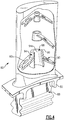
- Figure 3 shows the airfoil 60 with a portion of the first sidewall 74 cutaway to reveal the cavity 78 within the airfoil body 68.
- the airfoil 60 in this example is an uncooled structure and the cavity 78 is thus completely sealed from the exterior of the airfoil 60.
- the airfoil 60 includes a damper member 88 enclosed in the cavity 78.
- the damper member 88 is loose within the cavity 78 such that the damper member 88 is permitted to move at least longitudinally within the cavity 78.
- loose as used in this disclosure refer to the damper member 88 being free-floating, free of any rigid connections to any other structures, although neighboring structures may limit movement of the damper member 88.
- the damper member 88 is longitudinally elongated and tapers from the base 70 toward the tip end 72 of the airfoil portion 62.
- the damper member 88 has a geometric shape and in this example is generally conical. It is to be understood, however, that the damper member 88 can have other geometric shapes or even non-basic geometric shapes.
- the damper member 88 extends between a first terminal end 89a and a second terminal end 89b.
- the terminal ends 89a and 89b are free of any connection, rigid or otherwise, to the airfoil body 68.
- the damper member 88 is loose and free-floating within the cavity 78.
- the airfoil body 68 includes at least one guide member 90 that is fixed with regard to the first sidewall 74 and the second sidewall 76.
- the airfoil body 68 includes three such guide members 90a, 90b and 90c. It is to be understood, however, that the airfoil body 68 may alternatively include only a single guide member 90 or may include more than three guide members 90.
- Each of the guide members 90 includes a support arm 92 that is fixed to at least one of the first sidewalls 74 or the second sidewall 76.
- the support arm 92 is inclined with regard to the longitudinal axis L, to distribute load.
- the inclination of the support arm 92 could be inverted.
- Each of the guide members 90 includes a guide piece 94 supported on the respective support arm or arms 92.
- the guide piece 94 circumscribes the damper member 88 and includes an inner bearing surface 94a which, under certain circumstances that will be described below, contacts the damper member 88.
- the bearing surface 94a is frustoconical to provide an area contact with the conical shape of the damper member 88.
- the damper member 88 includes longitudinally alternating bearing sections 88a (bounded by dashed lines) and non-bearing sections 88b.
- the bearing sections 88a are sections of the damper member 88 that contact, or are able to contact, the bearing surfaces 94a of the guide members 90, while the non-bearing sections 88b do not contact, and are not able to contact, the bearing surfaces 94a of the guide members 90. That is, the damper member 88 has limited movement within the cavity 78.
- Figure 4 illustrates a view of the airfoil 60 without the damper member 88 such that the guide members 90 can be more clearly seen and Figure 5 shows a cross-section through a portion of the damper member 88 and guide piece 94 of guide member 90.
- the guide piece 94 includes a guide wall 96 that defines at least one opening 98 through which the damper member 88 extends.
- the guide wall 96 includes the bearing surface 94a.
- the three guide members 90a, 90b and 90c are longitudinally spaced apart from each other within the cavity 78.
- each of the support arms 92 includes an opening 92a there through (see also Figure 3 ) for weight-reduction of the airfoil 60.
- the loose damper member 88 may sit on the bottom of the cavity 78.
- the damper member 88 Upon rotation of the airfoil 60 about engine central axis A, the damper member 88 is thrown longitudinally outwardly toward the tip end 72 of the airfoil 60.
- the damper member 88 wedges against the bearing surfaces 94a of the guide pieces 94. The friction between the damper member 88 and the bearing surfaces 94a removes energy from the system and thus serves to dampen vibrations of the airfoil 60.
- the size and location of the damper member 88, size of the bearing surfaces 94a, number and size of guide members 90 and the location of attachments of the guide members 90 to the side walls 74/76 can be tailored to adjust the dampening effect.
- the contact area between the damper member 88 and the bearing surfaces 94 influences the amount of energy absorbed, and thus the dampening effect, at a particular location and can be tailored at a design stage by changing this contact area.
- a greater overall contact area provides a greater amount of energy absorbance and a lower overall contact area provides a relatively lesser amount of absorbance.
- FIG. 6 shows a portion of a modified airfoil 160.
- the airfoil 160 additionally includes a wing strut structure 191, which is connected to the guide member 190.
- the wing strut structure 191 in this example includes a longitudinally extending rib 193 connected with the first side wall 74 and the second side wall 76, and lateral ribs 195 that extend laterally with respect to the longitudinal axis L and connect the first side wall 74, the second side wall 76 and the longitudinally extending rib 193.
- the wing strut structure 191 reinforces the side walls 74 and 76, as well as the guide member 190.
- the damper member 88 spans lengthwise throughout most of the longitudinal length of the cavity 78. However, in other examples, the damper member 88 can be shorter or longer than shown. If the damper member 88 is shorter than shown, the bottom-most guide member 90a may be modified as shown in Figures 7A or 7B .
- the guide piece 194/194' is a cup having sidewalls 196, a bottom wall 198a/198a' that joins the sidewalls 196, and an open top 198b through which the damper member 188 extends.
- the second terminal end 189b of the damper member 188 is received into the guide piece 194/194' and sits on the bottom wall 198a/198a' when the airfoil 60 is in a static state.
- the bottom wall 198a is solid.
- the bottom wall 198a' has openings 199 to reduce weight and/or to permit powder removal in the additive manufacturing process described below.
- the cup-like structure can support the damper member 188 at any longitudinal position within the cavity 78.
- a method of processing an airfoil having the features disclosed herein includes an additive manufacturing process, as schematically illustrated in Figure 8 .
- Powdered metal suitable for aerospace airfoil applications is fed to a machine, which may provide a vacuum, for example.
- the machine deposits multiple layers of powdered metal onto one another.
- the layers are selectively joined to one another with reference to Computer-Aided Design data to form solid structures that relate to a particular cross-section of the airfoil.
- the powdered metal is selectively melted using a direct metal laser sintering process or an electron-beam melting process.
- an airfoil or portion thereof such as for a repair, with any or all of the above-described geometries, may be produced.
- the airfoil may be post-processed to provide desired structural characteristics. For example, the airfoil may be heated to reconfigure the joined layers into a single crystalline structure.
Landscapes
- Engineering & Computer Science (AREA)
- Mechanical Engineering (AREA)
- General Engineering & Computer Science (AREA)
- Manufacturing & Machinery (AREA)
- Structures Of Non-Positive Displacement Pumps (AREA)
- Turbine Rotor Nozzle Sealing (AREA)
Abstract
Description
- This disclosure relates to an airfoil, such as an airfoil for a gas turbine engine.
- Turbine, fan and compressor airfoil structures are typically manufactured using die casting techniques. For example, the airfoil is cast within a mold that defines an exterior airfoil surface. A core structure may be used within the mold to form impingement holes, cooling passages, ribs or other structures within the airfoil. The die casting technique inherently limits the geometry, size, wall thickness and location of airfoil structures. Thus, the design of a traditional airfoil is limited to structures that can be manufactured using the die casting technique, which in turn may limit the performance of the airfoil.
- An airfoil according to an exemplary aspect of the present disclosure includes an airfoil body that has a leading edge and a trailing edge and a first side wall and a second side wall that is spaced apart from the first side wall. The first side wall and the second side wall join the leading edge and the trailing edge and at least partially define a cavity in the airfoil body. A damper member is enclosed and loose within the cavity.
- In a further non-limiting embodiment of the above example, the damper member is tapered.
- A further non-limiting embodiment of any of the foregoing examples includes at least one guide member fixed with regard to the first sidewall and the second sidewall. At least one guide member includes a bearing surface that circumscribes the damper member.
- In a further non-limiting embodiment of any of the foregoing examples, the bearing surface is frustoconical.
- In a further non-limiting embodiment of any of the foregoing examples, the airfoil body defines a longitudinal axis, and the bearing surface is inclined with regard to the longitudinal axis.
- In a further non-limiting embodiment of any of the foregoing examples, the at least one guide member includes at least one support arm fixed to at least one of the first sidewall or the second sidewall, and a guide piece is supported on the least one support arm, the guide piece including a guide wall that defines an opening through which the damper member extends, the guide wall including the bearing surface.
- In a further non-limiting embodiment of any of the foregoing examples, the at least one support arm is inclined with respect to a longitudinal axis defined by the airfoil body.
- In a further non-limiting embodiment of any of the foregoing examples, the at least one support arm includes at least one opening there through.
- In a further non-limiting embodiment of any of the foregoing examples, the at least one guide member includes a plurality of guide members that are longitudinally spaced apart with respect to a longitudinal axis defined by the airfoil body.
- In a further non-limiting embodiment of any of the foregoing examples, the at least one guide member includes a cup having sidewalls, a bottom wall joining the sidewalls, and an open top through which the damper member extends.
- In a further non-limiting embodiment of any of the foregoing examples, the bottom wall includes openings extending there through.
- In a further non-limiting embodiment of any of the foregoing examples, the damper member is longitudinally elongated with respect to a longitudinal axis defined by the airfoil body.
- In a further non-limiting embodiment of any of the foregoing examples, the damper member extends between a first terminal end and a second terminal end, and the first terminal end and the second terminal end are free of any connection to the airfoil body.
- In a further non-limiting embodiment of any of the foregoing examples, the damper member includes longitudinally alternating bearing sections and non-bearing sections with respect to a longitudinal axis defined by the airfoil body.
- A turbine engine according to an exemplary aspect of the present disclosure includes, optionally a fan, a compressor section, a combustor in fluid communication with the compressor section, and a turbine section in fluid communication with the combustor. The turbine section is coupled to drive the compressor section and the fan. At least one of the fan, the compressor section and the turbine section includes an airfoil having an airfoil body including a leading edge and a trailing edge and a first side wall and a second side wall that is spaced apart from the first side wall. The first side wall and the second side wall join the leading edge and the trailing edge and at least partially define a cavity in the airfoil body. A damper member is enclosed and loose within the cavity.
- In a further non-limiting embodiment of any of the foregoing examples, the damper member is tapered.
- A further non-limiting embodiment of any of the foregoing examples includes at least one guide member fixed with regard to the first sidewall and the second sidewall, the at least one guide member includes a bearing surface that circumscribes the damper member.
- In a further non-limiting embodiment of any of the foregoing examples, the bearing surface is frustoconical.
- In a further non-limiting embodiment of any of the foregoing examples, the damper member includes longitudinally alternating bearing sections and non-bearing sections with respect to a longitudinal axis defined by the airfoil body.
- A method for processing an airfoil according to an exemplary aspect of the present disclosure includes depositing multiple layers of a powdered metal onto one another, joining the layers to one another with reference to data relating to a particular cross-section of an airfoil, and producing the airfoil with an airfoil body including a leading edge and a trailing edge and a first side wall and a second side wall that is spaced apart from the first side wall. The first side wall and the second side wall join the leading edge and the trailing edge and at least partially define a cavity in the airfoil body, and a damper member is enclosed and loose within the cavity.
- The various features and advantages of the present disclosure will become apparent to those skilled in the art from the following detailed description. The drawings that accompany the detailed description can be briefly described as follows.
-
Figure 1 shows an example gas turbine engine. -
Figure 2 shows a perspective view of an airfoil. -
Figure 3 shows the airfoil ofFigure 2 with a portion cutaway to reveal an interior cavity and damper member. -
Figure 4 shows the airfoil ofFigure 3 without the damper member. -
Figure 5 shows a cross-section of a damper member and a guide member. -
Figure 6 shows a portion of a modified airfoil having a wing strut. -
Figure 7A shows a cross-section of a damper member and a modified guide member having a cup structure. -
Figure 7B shows a cross-section of a another modified guide member having a cup structure. -
Figure 8 shows an example method for processing an airfoil. -
Figure 1 schematically illustrates agas turbine engine 20. Thegas turbine engine 20 is disclosed herein as a two-spool turbofan that generally incorporates afan section 22, acompressor section 24, a combustor section 26 and aturbine section 28. Alternative engines might include an augmentor section (not shown) among other systems or features. Thefan section 22 drives air along a bypass flowpath while thecompressor section 24 drives air along a core flowpath for compression and communication into the combustor section 26 then expansion through theturbine section 28. Although depicted as a turbofan gas turbine engine in the disclosed non-limiting embodiment, it should be understood that the concepts described herein are not limited to use with turbofans as the teachings may be applied to other types of turbine engines including three-spool architectures. - The
engine 20 generally includes afirst spool 30 and asecond spool 32 mounted for rotation about an engine central axis A relative to an enginestatic structure 36 viaseveral bearing systems 38. It should be understood thatvarious bearing systems 38 at various locations may alternatively or additionally be provided. - The
first spool 30 generally includes afirst shaft 40 that interconnects afan 42, afirst compressor 44 and a first turbine 46. Thefirst shaft 40 may be connected to thefan 42 through a gear assembly of a fandrive gear system 48 to drive thefan 42 at a lower speed than thefirst spool 30. Thesecond spool 32 includes asecond shaft 50 that interconnects asecond compressor 52 and second turbine 54. Thefirst spool 30 runs at a relatively lower pressure than thesecond spool 32. It is to be understood that "low pressure" and "high pressure" or variations thereof as used herein are relative terms indicating that the high pressure is greater than the low pressure. An annular combustor 56 is arranged between thesecond compressor 52 and the second turbine 54. Thefirst shaft 40 and thesecond shaft 50 are concentric and rotate viabearing systems 38 about the engine central axis A which is collinear with their longitudinal axes. - The core airflow is compressed by the
first compressor 44 then thesecond compressor 52, mixed and burned with fuel in the annular combustor 56, then expanded over the second turbine 54 and first turbine 46. The first turbine 46 and the second turbine 54 rotationally drive, respectively, thefirst spool 30 and thesecond spool 32 in response to the expansion. -
Figure 2 illustrates anexample airfoil 60. In this example, theairfoil 60 is a turbine blade of theturbine section 28. Theairfoil 60 may be mounted on a turbine disk in a known manner with a plurality of like airfoils. Alternatively, it is to be understood that although theairfoil 60 is depicted as a turbine blade, the disclosure is not limited to turbine blades and the concepts disclosed herein are applicable to turbine vanes, compressor airfoils (blades or vanes) in thecompressor section 24, fan airfoils in thefan section 22 or any other airfoil structures. Thus, some features that are particular to the illustrated turbine blade are to be considered optional. - The
airfoil 60 includes anairfoil portion 62, aplatform 64 and aroot 66. Theplatform 64 and theroot 66 are particular to the turbine blade and thus may differ in other airfoil structures or be excluded in other airfoil structures. - The
airfoil 60 includes abody 68 that defines a longitudinal axis L between a base 70 at theplatform 64 and atip end 72. The longitudinal axis L in this example is perpendicular to the engine central axis A. Thebody 68 includes a leading edge (LE) and a trailing edge (TE) and afirst side wall 74 and asecond side wall 76 that is spaced apart from thefirst side wall 74. Thefirst side wall 74 and thesecond side wall 76 join the leading edge (LE) and the trailing edge (TE) and at least partially define a cavity 78 (Figure 3 ) in thebody 68. - The
airfoil portion 62 connects to theplatform 64 at afillet 80. Theplatform 64 connects to theroot 66 atbuttresses 82. Theroot 66 generally includes aneck 84 and aserration portion 86 for securing theairfoil 60 in a disk. - It should be understood that relative positional terms such as "forward," "aft," "upper," "lower," "above," "below," "circumferential," "radial" and the like are with reference to the normal operational attitude and engine central axis A, unless otherwise indicated. Furthermore, with reference to the
engine 20, thetip end 72 of theairfoil 60 is commonly referred to as the outer diameter of theairfoil 60 and theroot 66 is commonly referred to as the inner diameter of theairfoil 60. Theplatform 64 includes anupper surface 64a that bounds an inner diameter of a gas path, generally shown as G, over theairfoil portion 62. Some airfoils may also include a platform at thetip end 72 that bounds an outer diameter of the gas path G. -
Figure 3 shows theairfoil 60 with a portion of thefirst sidewall 74 cutaway to reveal thecavity 78 within theairfoil body 68. Theairfoil 60 in this example is an uncooled structure and thecavity 78 is thus completely sealed from the exterior of theairfoil 60. Theairfoil 60 includes adamper member 88 enclosed in thecavity 78. Thedamper member 88 is loose within thecavity 78 such that thedamper member 88 is permitted to move at least longitudinally within thecavity 78. The term "loose" as used in this disclosure refer to thedamper member 88 being free-floating, free of any rigid connections to any other structures, although neighboring structures may limit movement of thedamper member 88. - In this example, the
damper member 88 is longitudinally elongated and tapers from the base 70 toward thetip end 72 of theairfoil portion 62. As an example, thedamper member 88 has a geometric shape and in this example is generally conical. It is to be understood, however, that thedamper member 88 can have other geometric shapes or even non-basic geometric shapes. - The
damper member 88 extends between a firstterminal end 89a and a secondterminal end 89b. The terminal ends 89a and 89b are free of any connection, rigid or otherwise, to theairfoil body 68. Thus, thedamper member 88 is loose and free-floating within thecavity 78. - The
airfoil body 68 includes at least oneguide member 90 that is fixed with regard to thefirst sidewall 74 and thesecond sidewall 76. In the illustrated example, theairfoil body 68 includes threesuch guide members airfoil body 68 may alternatively include only asingle guide member 90 or may include more than threeguide members 90. - Each of the
guide members 90 includes asupport arm 92 that is fixed to at least one of thefirst sidewalls 74 or thesecond sidewall 76. In the illustrated example, thesupport arm 92 is inclined with regard to the longitudinal axis L, to distribute load. Alternatively, the inclination of thesupport arm 92 could be inverted. - Each of the
guide members 90 includes aguide piece 94 supported on the respective support arm orarms 92. Theguide piece 94 circumscribes thedamper member 88 and includes aninner bearing surface 94a which, under certain circumstances that will be described below, contacts thedamper member 88. In this example, the bearingsurface 94a is frustoconical to provide an area contact with the conical shape of thedamper member 88. In that regard, thedamper member 88 includes longitudinally alternatingbearing sections 88a (bounded by dashed lines) andnon-bearing sections 88b. The bearingsections 88a are sections of thedamper member 88 that contact, or are able to contact, the bearing surfaces 94a of theguide members 90, while thenon-bearing sections 88b do not contact, and are not able to contact, the bearing surfaces 94a of theguide members 90. That is, thedamper member 88 has limited movement within thecavity 78. -
Figure 4 illustrates a view of theairfoil 60 without thedamper member 88 such that theguide members 90 can be more clearly seen andFigure 5 shows a cross-section through a portion of thedamper member 88 and guidepiece 94 ofguide member 90. - The
guide piece 94 includes aguide wall 96 that defines at least oneopening 98 through which thedamper member 88 extends. Theguide wall 96 includes the bearingsurface 94a. The threeguide members cavity 78. Optionally, each of thesupport arms 92 includes anopening 92a there through (see alsoFigure 3 ) for weight-reduction of theairfoil 60. - When the
airfoil 60 is in a static state, such as when theengine 20 in not in operation or theturbine section 28 is not rotating, theloose damper member 88 may sit on the bottom of thecavity 78. Upon rotation of theairfoil 60 about engine central axis A, thedamper member 88 is thrown longitudinally outwardly toward thetip end 72 of theairfoil 60. Thedamper member 88 wedges against the bearing surfaces 94a of theguide pieces 94. The friction between thedamper member 88 and the bearingsurfaces 94a removes energy from the system and thus serves to dampen vibrations of theairfoil 60. - As can be appreciated, the size and location of the
damper member 88, size of the bearingsurfaces 94a, number and size ofguide members 90 and the location of attachments of theguide members 90 to theside walls 74/76 can be tailored to adjust the dampening effect. As an example, the contact area between thedamper member 88 and the bearing surfaces 94 influences the amount of energy absorbed, and thus the dampening effect, at a particular location and can be tailored at a design stage by changing this contact area. A greater overall contact area provides a greater amount of energy absorbance and a lower overall contact area provides a relatively lesser amount of absorbance. -
Figure 6 shows a portion of a modifiedairfoil 160. In this disclosure, like reference numerals designate like elements where appropriate and reference numerals with the addition of one-hundred or multiples thereof designate modified elements that are understood to incorporate the same features and benefits of the corresponding elements. In this example, theairfoil 160 additionally includes awing strut structure 191, which is connected to theguide member 190. Thewing strut structure 191 in this example includes alongitudinally extending rib 193 connected with thefirst side wall 74 and thesecond side wall 76, andlateral ribs 195 that extend laterally with respect to the longitudinal axis L and connect thefirst side wall 74, thesecond side wall 76 and thelongitudinally extending rib 193. Thewing strut structure 191 reinforces theside walls guide member 190. - As shown in
Figure 3 , thedamper member 88 spans lengthwise throughout most of the longitudinal length of thecavity 78. However, in other examples, thedamper member 88 can be shorter or longer than shown. If thedamper member 88 is shorter than shown, thebottom-most guide member 90a may be modified as shown inFigures 7A or 7B . In this example, theguide piece 194/194' is acup having sidewalls 196, abottom wall 198a/198a' that joins thesidewalls 196, and an open top 198b through which thedamper member 188 extends. That is, the secondterminal end 189b of thedamper member 188 is received into theguide piece 194/194' and sits on thebottom wall 198a/198a' when theairfoil 60 is in a static state. In the example ofFigure 7A , thebottom wall 198a is solid. In the example ofFigure 7B , thebottom wall 198a' hasopenings 199 to reduce weight and/or to permit powder removal in the additive manufacturing process described below. Thus, the cup-like structure can support thedamper member 188 at any longitudinal position within thecavity 78. - The geometries disclosed herein may be difficult to form using conventional casting technologies. Thus, a method of processing an airfoil having the features disclosed herein includes an additive manufacturing process, as schematically illustrated in
Figure 8 . Powdered metal suitable for aerospace airfoil applications is fed to a machine, which may provide a vacuum, for example. The machine deposits multiple layers of powdered metal onto one another. The layers are selectively joined to one another with reference to Computer-Aided Design data to form solid structures that relate to a particular cross-section of the airfoil. In one example, the powdered metal is selectively melted using a direct metal laser sintering process or an electron-beam melting process. Other layers or portions of layers corresponding to negative features, such as cavities or openings, are not joined and thus remain as a powdered metal. The unjoined powder metal may later be removed using blown air, for example. With the layers built upon one another and joined to one another cross-section by cross-section, an airfoil or portion thereof, such as for a repair, with any or all of the above-described geometries, may be produced. The airfoil may be post-processed to provide desired structural characteristics. For example, the airfoil may be heated to reconfigure the joined layers into a single crystalline structure. - Although a combination of features is shown in the illustrated examples, not all of them need to be combined to realize the benefits of various embodiments of this disclosure. In other words, a system designed according to an embodiment of this disclosure will not necessarily include all of the features shown in any one of the Figures or all of the portions schematically shown in the Figures. Moreover, selected features of one example embodiment may be combined with selected features of other example embodiments.
- The preceding description is exemplary rather than limiting in nature. Variations and modifications to the disclosed examples may become apparent to those skilled in the art that do not necessarily depart from the essence of this disclosure. The scope of legal protection given to this disclosure can only be determined by studying the following claims.
Claims (15)
- An airfoil comprising:an airfoil body including a leading edge and a trailing edge and a first side wall and a second side wall that is spaced apart from the first side wall, the first side wall and the second side wall joining the leading edge and the trailing edge and at least partially defining a cavity in the airfoil body; anda damper member enclosed in the cavity, the damper member being loose within the cavity.
- The airfoil as recited in claim 1, wherein the damper member is tapered.
- The airfoil as recited in claim 1 or 2, further including at least one guide member fixed with regard to the first sidewall and the second sidewall, the at least one guide member including a bearing surface that circumscribes the damper member, optionally wherein the bearing surface is frustoconical.
- The airfoil as recited in claim 3, wherein the airfoil includes a wing strut structure which is connected to the at least one guide member.
- The airfoil as recited in claim 4, wherein the wing strut structure includes a longitudinally extending rib connected with the first side wall and the second side wall.
- The airfoil as recited in claim 5, wherein the wing strut structure includes lateral ribs that extend laterally with respect to a longitudinal axis and connect the first side wall, the second side wall and the longitudinally extending rib.
- The airfoil as recited in claim 3, wherein the at least one guide member includes at least one support arm fixed to at least one of the first sidewall or the second sidewall, and a guide piece is supported on the least one support arm, the guide piece including a guide wall that defines an opening through which the damper member extends, the guide wall including the bearing surface, optionally wherein:the at least one support arm is inclined with respect to a longitudinal axis defined by the airfoil body; and/orwherein the at least one support arm includes at least one opening there through.
- The airfoil as recited in any of claims 3 to 7, wherein the airfoil body defines a longitudinal axis, and the bearing surface is inclined with regard to the longitudinal axis.
- The airfoil as recited in any of claims 3 to 8, wherein the at least one guide member includes a plurality of guide members that are longitudinally spaced apart with respect to a longitudinal axis defined by the airfoil body.
- The airfoil as recited in any of claims 3 to 9, wherein the at least one guide member includes a cup having sidewalls, a bottom wall joining the sidewalls, and an open top through which the damper member extends.
- The airfoil as recited in claim 10, wherein the bottom wall includes openings extending there through.
- The airfoil as recited in any preceding claim, wherein the damper member is longitudinally elongated with respect to a longitudinal axis defined by the airfoil body, optionally wherein the damper member extends between a first terminal end and a second terminal end, and the first terminal end and the second terminal end are free of any connection to the airfoil body.
- The airfoil as recited in any preceding claim, wherein the damper member includes longitudinally alternating bearing sections and non-bearing sections with respect to a longitudinal axis defined by the airfoil body.
- A turbine engine comprising:optionally, a fan;a compressor section;a combustor in fluid communication with the compressor section; anda turbine section in fluid communication with the combustor, the turbine section being coupled to drive the compressor section and the fan, andat least one of the fan, the compressor section and the turbine section including an airfoil as recited in any preceding claim.
- A method for processing an airfoil, the method comprising:depositing multiple layers of a powdered metal onto one another;joining the layers to one another with reference to data relating to a particular cross-section of an airfoil; andproducing the airfoil with an airfoil body including a leading edge and a trailing edge and a first side wall and a second side wall that is spaced apart from the first side wall, the first side wall and the second side wall joining the leading edge and the trailing edge and at least partially defining a cavity in the airfoil body, and a damper member enclosed in the cavity, the damper member being loose within the cavity.
Applications Claiming Priority (3)
| Application Number | Priority Date | Filing Date | Title |
|---|---|---|---|
| US13/454,488 US9267380B2 (en) | 2012-04-24 | 2012-04-24 | Airfoil including loose damper |
| EP13782220.1A EP2841705B1 (en) | 2012-04-24 | 2013-04-20 | Airfoil and corresponding method for processing an airfoil |
| PCT/US2013/037501 WO2013163049A1 (en) | 2012-04-24 | 2013-04-20 | Airfoil including loose damper |
Related Parent Applications (1)
| Application Number | Title | Priority Date | Filing Date |
|---|---|---|---|
| EP13782220.1A Division EP2841705B1 (en) | 2012-04-24 | 2013-04-20 | Airfoil and corresponding method for processing an airfoil |
Publications (2)
| Publication Number | Publication Date |
|---|---|
| EP3633149A1 true EP3633149A1 (en) | 2020-04-08 |
| EP3633149B1 EP3633149B1 (en) | 2021-12-08 |
Family
ID=49378830
Family Applications (2)
| Application Number | Title | Priority Date | Filing Date |
|---|---|---|---|
| EP19213135.7A Active EP3633149B1 (en) | 2012-04-24 | 2013-04-20 | Airfoil, corresponding turbine engine and method for processing an airfoil |
| EP13782220.1A Active EP2841705B1 (en) | 2012-04-24 | 2013-04-20 | Airfoil and corresponding method for processing an airfoil |
Family Applications After (1)
| Application Number | Title | Priority Date | Filing Date |
|---|---|---|---|
| EP13782220.1A Active EP2841705B1 (en) | 2012-04-24 | 2013-04-20 | Airfoil and corresponding method for processing an airfoil |
Country Status (4)
| Country | Link |
|---|---|
| US (2) | US9267380B2 (en) |
| EP (2) | EP3633149B1 (en) |
| SG (1) | SG11201406226VA (en) |
| WO (1) | WO2013163049A1 (en) |
Families Citing this family (12)
| Publication number | Priority date | Publication date | Assignee | Title |
|---|---|---|---|---|
| US10697303B2 (en) | 2013-04-23 | 2020-06-30 | United Technologies Corporation | Internally damped airfoiled component and method |
| US10914320B2 (en) * | 2014-01-24 | 2021-02-09 | Raytheon Technologies Corporation | Additive manufacturing process grown integrated torsional damper mechanism in gas turbine engine blade |
| JP6503698B2 (en) * | 2014-11-17 | 2019-04-24 | 株式会社Ihi | Axial machine wing |
| US10577940B2 (en) | 2017-01-31 | 2020-03-03 | General Electric Company | Turbomachine rotor blade |
| US10934868B2 (en) * | 2018-09-12 | 2021-03-02 | Rolls-Royce North American Technologies Inc. | Turbine vane assembly with variable position support |
| US11371358B2 (en) | 2020-02-19 | 2022-06-28 | General Electric Company | Turbine damper |
| US11624287B2 (en) * | 2020-02-21 | 2023-04-11 | Raytheon Technologies Corporation | Ceramic matrix composite component having low density core and method of making |
| US11739645B2 (en) | 2020-09-30 | 2023-08-29 | General Electric Company | Vibrational dampening elements |
| US12371998B2 (en) * | 2023-06-29 | 2025-07-29 | Ge Infrastructure Technology Llc | Nested damper pin and vibration dampening system for turbine nozzle or blade |
| US12421856B2 (en) | 2023-06-29 | 2025-09-23 | Ge Infrastructure Technology Llc | Damper element with flexible legs for vibration dampening system for turbine blade |
| US12276205B2 (en) * | 2023-06-29 | 2025-04-15 | Ge Infrastructure Technology Llc | Damper element with flexible legs for vibration dampening system for turbine blade |
| US12553349B2 (en) | 2023-06-29 | 2026-02-17 | Ge Infrastructure Technology Llc | Vibration dampening system including resonant-tuned elongated body for damper element(s) for turbine component |
Citations (6)
| Publication number | Priority date | Publication date | Assignee | Title |
|---|---|---|---|---|
| US1833751A (en) * | 1929-07-05 | 1931-11-24 | Gen Electric | Vibration damping device |
| GB561897A (en) * | 1941-03-08 | 1944-06-09 | Westinghouse Electric Int Co | Improvements in or relating to vibration damping means for turbine blades |
| US6193465B1 (en) * | 1998-09-28 | 2001-02-27 | General Electric Company | Trapped insert turbine airfoil |
| US20050169754A1 (en) * | 2004-02-04 | 2005-08-04 | United Technologies Corporation | Cooled rotor blade with vibration damping device |
| US20080290215A1 (en) * | 2007-05-23 | 2008-11-27 | Rolls-Royce Plc | Hollow aerofoil and a method of manufacturing a hollow aerofoil |
| WO2011019412A2 (en) * | 2009-08-13 | 2011-02-17 | Siemens Energy, Inc. | Turbine blade having a constant thickness airfoil skin |
Family Cites Families (22)
| Publication number | Priority date | Publication date | Assignee | Title |
|---|---|---|---|---|
| US1883751A (en) | 1930-01-13 | 1932-10-18 | John Ormond Ker | Animal mouth tongs |
| US2343918A (en) | 1943-05-11 | 1944-03-14 | Howard M Mccoy | Means for deicing propeller spinners |
| US4815939A (en) | 1986-11-03 | 1989-03-28 | Airfoil Textron Inc. | Twisted hollow airfoil with non-twisted internal support ribs |
| US5038014A (en) | 1989-02-08 | 1991-08-06 | General Electric Company | Fabrication of components by layered deposition |
| US5165860A (en) | 1991-05-20 | 1992-11-24 | United Technologies Corporation | Damped airfoil blade |
| US5232344A (en) * | 1992-01-17 | 1993-08-03 | United Technologies Corporation | Internally damped blades |
| US5407321A (en) * | 1993-11-29 | 1995-04-18 | United Technologies Corporation | Damping means for hollow stator vane airfoils |
| US5837960A (en) | 1995-08-14 | 1998-11-17 | The Regents Of The University Of California | Laser production of articles from powders |
| GB9906450D0 (en) | 1999-03-19 | 1999-05-12 | Rolls Royce Plc | Aerofoil blade damper |
| US6391251B1 (en) | 1999-07-07 | 2002-05-21 | Optomec Design Company | Forming structures from CAD solid models |
| GB0100695D0 (en) | 2001-01-11 | 2001-02-21 | Rolls Royce Plc | a turbomachine blade |
| US7029232B2 (en) | 2003-02-27 | 2006-04-18 | Rolls-Royce Plc | Abradable seals |
| GB2403987B (en) | 2003-07-11 | 2006-09-06 | Rolls Royce Plc | Blades |
| US7121801B2 (en) | 2004-02-13 | 2006-10-17 | United Technologies Corporation | Cooled rotor blade with vibration damping device |
| US7217093B2 (en) | 2004-05-27 | 2007-05-15 | United Technologies Corporation | Rotor blade with a stick damper |
| US7121800B2 (en) | 2004-09-13 | 2006-10-17 | United Technologies Corporation | Turbine blade nested seal damper assembly |
| US7270517B2 (en) | 2005-10-06 | 2007-09-18 | Siemens Power Generation, Inc. | Turbine blade with vibration damper |
| DE102006004090A1 (en) | 2006-01-28 | 2007-08-02 | Mtu Aero Engines Gmbh | Guide blade segment for gas turbine, has guide blade and inner cover band, where integral component of inner cover band, is sealing element, which seals radial inner gap between guide blade segment and gas turbine rotor |
| US7824158B2 (en) * | 2007-06-25 | 2010-11-02 | General Electric Company | Bimaterial turbine blade damper |
| US7857588B2 (en) | 2007-07-06 | 2010-12-28 | United Technologies Corporation | Reinforced airfoils |
| GB2459262B (en) | 2008-04-15 | 2010-09-22 | Rolls Royce Plc | Solid freeform fabricated damper |
| WO2011019661A1 (en) | 2009-08-09 | 2011-02-17 | Rolls-Royce Corporation | Method for forming a cast article |
-
2012
- 2012-04-24 US US13/454,488 patent/US9267380B2/en active Active
-
2013
- 2013-04-20 SG SG11201406226VA patent/SG11201406226VA/en unknown
- 2013-04-20 EP EP19213135.7A patent/EP3633149B1/en active Active
- 2013-04-20 WO PCT/US2013/037501 patent/WO2013163049A1/en not_active Ceased
- 2013-04-20 EP EP13782220.1A patent/EP2841705B1/en active Active
-
2016
- 2016-02-12 US US15/042,840 patent/US10151204B2/en active Active
Patent Citations (6)
| Publication number | Priority date | Publication date | Assignee | Title |
|---|---|---|---|---|
| US1833751A (en) * | 1929-07-05 | 1931-11-24 | Gen Electric | Vibration damping device |
| GB561897A (en) * | 1941-03-08 | 1944-06-09 | Westinghouse Electric Int Co | Improvements in or relating to vibration damping means for turbine blades |
| US6193465B1 (en) * | 1998-09-28 | 2001-02-27 | General Electric Company | Trapped insert turbine airfoil |
| US20050169754A1 (en) * | 2004-02-04 | 2005-08-04 | United Technologies Corporation | Cooled rotor blade with vibration damping device |
| US20080290215A1 (en) * | 2007-05-23 | 2008-11-27 | Rolls-Royce Plc | Hollow aerofoil and a method of manufacturing a hollow aerofoil |
| WO2011019412A2 (en) * | 2009-08-13 | 2011-02-17 | Siemens Energy, Inc. | Turbine blade having a constant thickness airfoil skin |
Also Published As
| Publication number | Publication date |
|---|---|
| EP2841705B1 (en) | 2019-12-11 |
| WO2013163049A1 (en) | 2013-10-31 |
| US9267380B2 (en) | 2016-02-23 |
| EP3633149B1 (en) | 2021-12-08 |
| US10151204B2 (en) | 2018-12-11 |
| US20130276457A1 (en) | 2013-10-24 |
| EP2841705A1 (en) | 2015-03-04 |
| SG11201406226VA (en) | 2015-01-29 |
| EP2841705A4 (en) | 2015-04-29 |
| US20160160651A1 (en) | 2016-06-09 |
Similar Documents
| Publication | Publication Date | Title |
|---|---|---|
| EP3633149B1 (en) | Airfoil, corresponding turbine engine and method for processing an airfoil | |
| EP2841699B1 (en) | Airfoil including damper member | |
| US9470095B2 (en) | Airfoil having internal lattice network | |
| EP2841709B1 (en) | Airfoil with break-way, free-floating damper member | |
| EP2841697B1 (en) | Airfoil including member connected by articulated joint | |
| US9879559B2 (en) | Airfoils having porous abradable elements | |
| EP2841702B1 (en) | Airfoil having tapered buttress | |
| EP2841704B1 (en) | Airfoil and corresponding method for processing an airfoil | |
| US9404369B2 (en) | Airfoil having minimum distance ribs |
Legal Events
| Date | Code | Title | Description |
|---|---|---|---|
| PUAI | Public reference made under article 153(3) epc to a published international application that has entered the european phase |
Free format text: ORIGINAL CODE: 0009012 |
|
| STAA | Information on the status of an ep patent application or granted ep patent |
Free format text: STATUS: THE APPLICATION HAS BEEN PUBLISHED |
|
| AC | Divisional application: reference to earlier application |
Ref document number: 2841705 Country of ref document: EP Kind code of ref document: P |
|
| AK | Designated contracting states |
Kind code of ref document: A1 Designated state(s): AL AT BE BG CH CY CZ DE DK EE ES FI FR GB GR HR HU IE IS IT LI LT LU LV MC MK MT NL NO PL PT RO RS SE SI SK SM TR |
|
| STAA | Information on the status of an ep patent application or granted ep patent |
Free format text: STATUS: REQUEST FOR EXAMINATION WAS MADE |
|
| 17P | Request for examination filed |
Effective date: 20201008 |
|
| RBV | Designated contracting states (corrected) |
Designated state(s): AL AT BE BG CH CY CZ DE DK EE ES FI FR GB GR HR HU IE IS IT LI LT LU LV MC MK MT NL NO PL PT RO RS SE SI SK SM TR |
|
| RAP1 | Party data changed (applicant data changed or rights of an application transferred) |
Owner name: RAYTHEON TECHNOLOGIES CORPORATION |
|
| GRAP | Despatch of communication of intention to grant a patent |
Free format text: ORIGINAL CODE: EPIDOSNIGR1 |
|
| STAA | Information on the status of an ep patent application or granted ep patent |
Free format text: STATUS: GRANT OF PATENT IS INTENDED |
|
| INTG | Intention to grant announced |
Effective date: 20210622 |
|
| GRAS | Grant fee paid |
Free format text: ORIGINAL CODE: EPIDOSNIGR3 |
|
| GRAA | (expected) grant |
Free format text: ORIGINAL CODE: 0009210 |
|
| STAA | Information on the status of an ep patent application or granted ep patent |
Free format text: STATUS: THE PATENT HAS BEEN GRANTED |
|
| AC | Divisional application: reference to earlier application |
Ref document number: 2841705 Country of ref document: EP Kind code of ref document: P |
|
| AK | Designated contracting states |
Kind code of ref document: B1 Designated state(s): AL AT BE BG CH CY CZ DE DK EE ES FI FR GB GR HR HU IE IS IT LI LT LU LV MC MK MT NL NO PL PT RO RS SE SI SK SM TR |
|
| REG | Reference to a national code |
Ref country code: GB Ref legal event code: FG4D |
|
| REG | Reference to a national code |
Ref country code: AT Ref legal event code: REF Ref document number: 1453925 Country of ref document: AT Kind code of ref document: T Effective date: 20211215 Ref country code: CH Ref legal event code: EP |
|
| REG | Reference to a national code |
Ref country code: DE Ref legal event code: R096 Ref document number: 602013080391 Country of ref document: DE |
|
| REG | Reference to a national code |
Ref country code: IE Ref legal event code: FG4D |
|
| REG | Reference to a national code |
Ref country code: LT Ref legal event code: MG9D |
|
| REG | Reference to a national code |
Ref country code: NL Ref legal event code: MP Effective date: 20211208 |
|
| PG25 | Lapsed in a contracting state [announced via postgrant information from national office to epo] |
Ref country code: RS Free format text: LAPSE BECAUSE OF FAILURE TO SUBMIT A TRANSLATION OF THE DESCRIPTION OR TO PAY THE FEE WITHIN THE PRESCRIBED TIME-LIMIT Effective date: 20211208 Ref country code: LT Free format text: LAPSE BECAUSE OF FAILURE TO SUBMIT A TRANSLATION OF THE DESCRIPTION OR TO PAY THE FEE WITHIN THE PRESCRIBED TIME-LIMIT Effective date: 20211208 Ref country code: FI Free format text: LAPSE BECAUSE OF FAILURE TO SUBMIT A TRANSLATION OF THE DESCRIPTION OR TO PAY THE FEE WITHIN THE PRESCRIBED TIME-LIMIT Effective date: 20211208 Ref country code: BG Free format text: LAPSE BECAUSE OF FAILURE TO SUBMIT A TRANSLATION OF THE DESCRIPTION OR TO PAY THE FEE WITHIN THE PRESCRIBED TIME-LIMIT Effective date: 20220308 |
|
| REG | Reference to a national code |
Ref country code: AT Ref legal event code: MK05 Ref document number: 1453925 Country of ref document: AT Kind code of ref document: T Effective date: 20211208 |
|
| PG25 | Lapsed in a contracting state [announced via postgrant information from national office to epo] |
Ref country code: SE Free format text: LAPSE BECAUSE OF FAILURE TO SUBMIT A TRANSLATION OF THE DESCRIPTION OR TO PAY THE FEE WITHIN THE PRESCRIBED TIME-LIMIT Effective date: 20211208 Ref country code: NO Free format text: LAPSE BECAUSE OF FAILURE TO SUBMIT A TRANSLATION OF THE DESCRIPTION OR TO PAY THE FEE WITHIN THE PRESCRIBED TIME-LIMIT Effective date: 20220308 Ref country code: LV Free format text: LAPSE BECAUSE OF FAILURE TO SUBMIT A TRANSLATION OF THE DESCRIPTION OR TO PAY THE FEE WITHIN THE PRESCRIBED TIME-LIMIT Effective date: 20211208 Ref country code: HR Free format text: LAPSE BECAUSE OF FAILURE TO SUBMIT A TRANSLATION OF THE DESCRIPTION OR TO PAY THE FEE WITHIN THE PRESCRIBED TIME-LIMIT Effective date: 20211208 Ref country code: GR Free format text: LAPSE BECAUSE OF FAILURE TO SUBMIT A TRANSLATION OF THE DESCRIPTION OR TO PAY THE FEE WITHIN THE PRESCRIBED TIME-LIMIT Effective date: 20220309 Ref country code: ES Free format text: LAPSE BECAUSE OF FAILURE TO SUBMIT A TRANSLATION OF THE DESCRIPTION OR TO PAY THE FEE WITHIN THE PRESCRIBED TIME-LIMIT Effective date: 20211208 |
|
| PG25 | Lapsed in a contracting state [announced via postgrant information from national office to epo] |
Ref country code: NL Free format text: LAPSE BECAUSE OF FAILURE TO SUBMIT A TRANSLATION OF THE DESCRIPTION OR TO PAY THE FEE WITHIN THE PRESCRIBED TIME-LIMIT Effective date: 20211208 |
|
| PG25 | Lapsed in a contracting state [announced via postgrant information from national office to epo] |
Ref country code: SM Free format text: LAPSE BECAUSE OF FAILURE TO SUBMIT A TRANSLATION OF THE DESCRIPTION OR TO PAY THE FEE WITHIN THE PRESCRIBED TIME-LIMIT Effective date: 20211208 Ref country code: SK Free format text: LAPSE BECAUSE OF FAILURE TO SUBMIT A TRANSLATION OF THE DESCRIPTION OR TO PAY THE FEE WITHIN THE PRESCRIBED TIME-LIMIT Effective date: 20211208 Ref country code: RO Free format text: LAPSE BECAUSE OF FAILURE TO SUBMIT A TRANSLATION OF THE DESCRIPTION OR TO PAY THE FEE WITHIN THE PRESCRIBED TIME-LIMIT Effective date: 20211208 Ref country code: PT Free format text: LAPSE BECAUSE OF FAILURE TO SUBMIT A TRANSLATION OF THE DESCRIPTION OR TO PAY THE FEE WITHIN THE PRESCRIBED TIME-LIMIT Effective date: 20220408 Ref country code: EE Free format text: LAPSE BECAUSE OF FAILURE TO SUBMIT A TRANSLATION OF THE DESCRIPTION OR TO PAY THE FEE WITHIN THE PRESCRIBED TIME-LIMIT Effective date: 20211208 Ref country code: CZ Free format text: LAPSE BECAUSE OF FAILURE TO SUBMIT A TRANSLATION OF THE DESCRIPTION OR TO PAY THE FEE WITHIN THE PRESCRIBED TIME-LIMIT Effective date: 20211208 |
|
| PG25 | Lapsed in a contracting state [announced via postgrant information from national office to epo] |
Ref country code: PL Free format text: LAPSE BECAUSE OF FAILURE TO SUBMIT A TRANSLATION OF THE DESCRIPTION OR TO PAY THE FEE WITHIN THE PRESCRIBED TIME-LIMIT Effective date: 20211208 Ref country code: AT Free format text: LAPSE BECAUSE OF FAILURE TO SUBMIT A TRANSLATION OF THE DESCRIPTION OR TO PAY THE FEE WITHIN THE PRESCRIBED TIME-LIMIT Effective date: 20211208 |
|
| REG | Reference to a national code |
Ref country code: DE Ref legal event code: R097 Ref document number: 602013080391 Country of ref document: DE |
|
| PG25 | Lapsed in a contracting state [announced via postgrant information from national office to epo] |
Ref country code: IS Free format text: LAPSE BECAUSE OF FAILURE TO SUBMIT A TRANSLATION OF THE DESCRIPTION OR TO PAY THE FEE WITHIN THE PRESCRIBED TIME-LIMIT Effective date: 20220408 |
|
| PLBE | No opposition filed within time limit |
Free format text: ORIGINAL CODE: 0009261 |
|
| STAA | Information on the status of an ep patent application or granted ep patent |
Free format text: STATUS: NO OPPOSITION FILED WITHIN TIME LIMIT |
|
| PG25 | Lapsed in a contracting state [announced via postgrant information from national office to epo] |
Ref country code: DK Free format text: LAPSE BECAUSE OF FAILURE TO SUBMIT A TRANSLATION OF THE DESCRIPTION OR TO PAY THE FEE WITHIN THE PRESCRIBED TIME-LIMIT Effective date: 20211208 Ref country code: AL Free format text: LAPSE BECAUSE OF FAILURE TO SUBMIT A TRANSLATION OF THE DESCRIPTION OR TO PAY THE FEE WITHIN THE PRESCRIBED TIME-LIMIT Effective date: 20211208 |
|
| 26N | No opposition filed |
Effective date: 20220909 |
|
| PG25 | Lapsed in a contracting state [announced via postgrant information from national office to epo] |
Ref country code: SI Free format text: LAPSE BECAUSE OF FAILURE TO SUBMIT A TRANSLATION OF THE DESCRIPTION OR TO PAY THE FEE WITHIN THE PRESCRIBED TIME-LIMIT Effective date: 20211208 |
|
| REG | Reference to a national code |
Ref country code: CH Ref legal event code: PL |
|
| REG | Reference to a national code |
Ref country code: BE Ref legal event code: MM Effective date: 20220430 |
|
| PG25 | Lapsed in a contracting state [announced via postgrant information from national office to epo] |
Ref country code: MC Free format text: LAPSE BECAUSE OF FAILURE TO SUBMIT A TRANSLATION OF THE DESCRIPTION OR TO PAY THE FEE WITHIN THE PRESCRIBED TIME-LIMIT Effective date: 20211208 Ref country code: LU Free format text: LAPSE BECAUSE OF NON-PAYMENT OF DUE FEES Effective date: 20220420 Ref country code: LI Free format text: LAPSE BECAUSE OF NON-PAYMENT OF DUE FEES Effective date: 20220430 Ref country code: CH Free format text: LAPSE BECAUSE OF NON-PAYMENT OF DUE FEES Effective date: 20220430 |
|
| PG25 | Lapsed in a contracting state [announced via postgrant information from national office to epo] |
Ref country code: BE Free format text: LAPSE BECAUSE OF NON-PAYMENT OF DUE FEES Effective date: 20220430 |
|
| PG25 | Lapsed in a contracting state [announced via postgrant information from national office to epo] |
Ref country code: IE Free format text: LAPSE BECAUSE OF NON-PAYMENT OF DUE FEES Effective date: 20220420 |
|
| PG25 | Lapsed in a contracting state [announced via postgrant information from national office to epo] |
Ref country code: IT Free format text: LAPSE BECAUSE OF FAILURE TO SUBMIT A TRANSLATION OF THE DESCRIPTION OR TO PAY THE FEE WITHIN THE PRESCRIBED TIME-LIMIT Effective date: 20211208 |
|
| P01 | Opt-out of the competence of the unified patent court (upc) registered |
Effective date: 20230521 |
|
| PG25 | Lapsed in a contracting state [announced via postgrant information from national office to epo] |
Ref country code: MK Free format text: LAPSE BECAUSE OF FAILURE TO SUBMIT A TRANSLATION OF THE DESCRIPTION OR TO PAY THE FEE WITHIN THE PRESCRIBED TIME-LIMIT Effective date: 20211208 Ref country code: CY Free format text: LAPSE BECAUSE OF FAILURE TO SUBMIT A TRANSLATION OF THE DESCRIPTION OR TO PAY THE FEE WITHIN THE PRESCRIBED TIME-LIMIT Effective date: 20211208 |
|
| PG25 | Lapsed in a contracting state [announced via postgrant information from national office to epo] |
Ref country code: HU Free format text: LAPSE BECAUSE OF FAILURE TO SUBMIT A TRANSLATION OF THE DESCRIPTION OR TO PAY THE FEE WITHIN THE PRESCRIBED TIME-LIMIT; INVALID AB INITIO Effective date: 20130420 |
|
| PG25 | Lapsed in a contracting state [announced via postgrant information from national office to epo] |
Ref country code: TR Free format text: LAPSE BECAUSE OF FAILURE TO SUBMIT A TRANSLATION OF THE DESCRIPTION OR TO PAY THE FEE WITHIN THE PRESCRIBED TIME-LIMIT Effective date: 20211208 |
|
| PG25 | Lapsed in a contracting state [announced via postgrant information from national office to epo] |
Ref country code: MT Free format text: LAPSE BECAUSE OF FAILURE TO SUBMIT A TRANSLATION OF THE DESCRIPTION OR TO PAY THE FEE WITHIN THE PRESCRIBED TIME-LIMIT Effective date: 20211208 |
|
| PGFP | Annual fee paid to national office [announced via postgrant information from national office to epo] |
Ref country code: FR Payment date: 20250319 Year of fee payment: 13 |
|
| PGFP | Annual fee paid to national office [announced via postgrant information from national office to epo] |
Ref country code: GB Payment date: 20250319 Year of fee payment: 13 |
|
| PGFP | Annual fee paid to national office [announced via postgrant information from national office to epo] |
Ref country code: DE Payment date: 20250319 Year of fee payment: 13 |
|
| REG | Reference to a national code |
Ref country code: DE Ref legal event code: R081 Ref document number: 602013080391 Country of ref document: DE Owner name: RTX CORPORATION (N.D.GES.D. STAATES DELAWARE),, US Free format text: FORMER OWNER: RAYTHEON TECHNOLOGIES CORPORATION, FARMINGTON, CT, US |