EP3632758A2 - Actuator controller and vehicle-installed system - Google Patents
Actuator controller and vehicle-installed system Download PDFInfo
- Publication number
- EP3632758A2 EP3632758A2 EP19196251.3A EP19196251A EP3632758A2 EP 3632758 A2 EP3632758 A2 EP 3632758A2 EP 19196251 A EP19196251 A EP 19196251A EP 3632758 A2 EP3632758 A2 EP 3632758A2
- Authority
- EP
- European Patent Office
- Prior art keywords
- current
- requested
- vehicle
- actuators
- voltage
- Prior art date
- Legal status (The legal status is an assumption and is not a legal conclusion. Google has not performed a legal analysis and makes no representation as to the accuracy of the status listed.)
- Granted
Links
Images





Classifications
-
- B—PERFORMING OPERATIONS; TRANSPORTING
- B60—VEHICLES IN GENERAL
- B60T—VEHICLE BRAKE CONTROL SYSTEMS OR PARTS THEREOF; BRAKE CONTROL SYSTEMS OR PARTS THEREOF, IN GENERAL; ARRANGEMENT OF BRAKING ELEMENTS ON VEHICLES IN GENERAL; PORTABLE DEVICES FOR PREVENTING UNWANTED MOVEMENT OF VEHICLES; VEHICLE MODIFICATIONS TO FACILITATE COOLING OF BRAKES
- B60T8/00—Arrangements for adjusting wheel-braking force to meet varying vehicular or ground-surface conditions, e.g. limiting or varying distribution of braking force
- B60T8/17—Using electrical or electronic regulation means to control braking
- B60T8/172—Determining control parameters used in the regulation, e.g. by calculations involving measured or detected parameters
-
- B—PERFORMING OPERATIONS; TRANSPORTING
- B60—VEHICLES IN GENERAL
- B60T—VEHICLE BRAKE CONTROL SYSTEMS OR PARTS THEREOF; BRAKE CONTROL SYSTEMS OR PARTS THEREOF, IN GENERAL; ARRANGEMENT OF BRAKING ELEMENTS ON VEHICLES IN GENERAL; PORTABLE DEVICES FOR PREVENTING UNWANTED MOVEMENT OF VEHICLES; VEHICLE MODIFICATIONS TO FACILITATE COOLING OF BRAKES
- B60T8/00—Arrangements for adjusting wheel-braking force to meet varying vehicular or ground-surface conditions, e.g. limiting or varying distribution of braking force
- B60T8/32—Arrangements for adjusting wheel-braking force to meet varying vehicular or ground-surface conditions, e.g. limiting or varying distribution of braking force responsive to a speed condition, e.g. acceleration or deceleration
- B60T8/88—Arrangements for adjusting wheel-braking force to meet varying vehicular or ground-surface conditions, e.g. limiting or varying distribution of braking force responsive to a speed condition, e.g. acceleration or deceleration with failure responsive means, i.e. means for detecting and indicating faulty operation of the speed responsive control means
- B60T8/885—Arrangements for adjusting wheel-braking force to meet varying vehicular or ground-surface conditions, e.g. limiting or varying distribution of braking force responsive to a speed condition, e.g. acceleration or deceleration with failure responsive means, i.e. means for detecting and indicating faulty operation of the speed responsive control means using electrical circuitry
-
- B—PERFORMING OPERATIONS; TRANSPORTING
- B60—VEHICLES IN GENERAL
- B60T—VEHICLE BRAKE CONTROL SYSTEMS OR PARTS THEREOF; BRAKE CONTROL SYSTEMS OR PARTS THEREOF, IN GENERAL; ARRANGEMENT OF BRAKING ELEMENTS ON VEHICLES IN GENERAL; PORTABLE DEVICES FOR PREVENTING UNWANTED MOVEMENT OF VEHICLES; VEHICLE MODIFICATIONS TO FACILITATE COOLING OF BRAKES
- B60T17/00—Component parts, details, or accessories of power brake systems not covered by groups B60T8/00, B60T13/00 or B60T15/00, or presenting other characteristic features
- B60T17/18—Safety devices; Monitoring
-
- B—PERFORMING OPERATIONS; TRANSPORTING
- B60—VEHICLES IN GENERAL
- B60R—VEHICLES, VEHICLE FITTINGS, OR VEHICLE PARTS, NOT OTHERWISE PROVIDED FOR
- B60R16/00—Electric or fluid circuits specially adapted for vehicles and not otherwise provided for; Arrangement of elements of electric or fluid circuits specially adapted for vehicles and not otherwise provided for
- B60R16/02—Electric or fluid circuits specially adapted for vehicles and not otherwise provided for; Arrangement of elements of electric or fluid circuits specially adapted for vehicles and not otherwise provided for electric constitutive elements
- B60R16/03—Electric or fluid circuits specially adapted for vehicles and not otherwise provided for; Arrangement of elements of electric or fluid circuits specially adapted for vehicles and not otherwise provided for electric constitutive elements for supply of electrical power to vehicle subsystems or for
-
- B—PERFORMING OPERATIONS; TRANSPORTING
- B60—VEHICLES IN GENERAL
- B60T—VEHICLE BRAKE CONTROL SYSTEMS OR PARTS THEREOF; BRAKE CONTROL SYSTEMS OR PARTS THEREOF, IN GENERAL; ARRANGEMENT OF BRAKING ELEMENTS ON VEHICLES IN GENERAL; PORTABLE DEVICES FOR PREVENTING UNWANTED MOVEMENT OF VEHICLES; VEHICLE MODIFICATIONS TO FACILITATE COOLING OF BRAKES
- B60T13/00—Transmitting braking action from initiating means to ultimate brake actuator with power assistance or drive; Brake systems incorporating such transmitting means, e.g. air-pressure brake systems
- B60T13/10—Transmitting braking action from initiating means to ultimate brake actuator with power assistance or drive; Brake systems incorporating such transmitting means, e.g. air-pressure brake systems with fluid assistance, drive, or release
- B60T13/12—Transmitting braking action from initiating means to ultimate brake actuator with power assistance or drive; Brake systems incorporating such transmitting means, e.g. air-pressure brake systems with fluid assistance, drive, or release the fluid being liquid
- B60T13/14—Transmitting braking action from initiating means to ultimate brake actuator with power assistance or drive; Brake systems incorporating such transmitting means, e.g. air-pressure brake systems with fluid assistance, drive, or release the fluid being liquid using accumulators or reservoirs fed by pumps
- B60T13/142—Systems with master cylinder
- B60T13/145—Master cylinder integrated or hydraulically coupled with booster
- B60T13/146—Part of the system directly actuated by booster pressure
-
- B—PERFORMING OPERATIONS; TRANSPORTING
- B60—VEHICLES IN GENERAL
- B60T—VEHICLE BRAKE CONTROL SYSTEMS OR PARTS THEREOF; BRAKE CONTROL SYSTEMS OR PARTS THEREOF, IN GENERAL; ARRANGEMENT OF BRAKING ELEMENTS ON VEHICLES IN GENERAL; PORTABLE DEVICES FOR PREVENTING UNWANTED MOVEMENT OF VEHICLES; VEHICLE MODIFICATIONS TO FACILITATE COOLING OF BRAKES
- B60T13/00—Transmitting braking action from initiating means to ultimate brake actuator with power assistance or drive; Brake systems incorporating such transmitting means, e.g. air-pressure brake systems
- B60T13/10—Transmitting braking action from initiating means to ultimate brake actuator with power assistance or drive; Brake systems incorporating such transmitting means, e.g. air-pressure brake systems with fluid assistance, drive, or release
- B60T13/66—Electrical control in fluid-pressure brake systems
- B60T13/662—Electrical control in fluid-pressure brake systems characterised by specified functions of the control system components
-
- B—PERFORMING OPERATIONS; TRANSPORTING
- B60—VEHICLES IN GENERAL
- B60T—VEHICLE BRAKE CONTROL SYSTEMS OR PARTS THEREOF; BRAKE CONTROL SYSTEMS OR PARTS THEREOF, IN GENERAL; ARRANGEMENT OF BRAKING ELEMENTS ON VEHICLES IN GENERAL; PORTABLE DEVICES FOR PREVENTING UNWANTED MOVEMENT OF VEHICLES; VEHICLE MODIFICATIONS TO FACILITATE COOLING OF BRAKES
- B60T13/00—Transmitting braking action from initiating means to ultimate brake actuator with power assistance or drive; Brake systems incorporating such transmitting means, e.g. air-pressure brake systems
- B60T13/10—Transmitting braking action from initiating means to ultimate brake actuator with power assistance or drive; Brake systems incorporating such transmitting means, e.g. air-pressure brake systems with fluid assistance, drive, or release
- B60T13/66—Electrical control in fluid-pressure brake systems
- B60T13/68—Electrical control in fluid-pressure brake systems by electrically-controlled valves
- B60T13/686—Electrical control in fluid-pressure brake systems by electrically-controlled valves in hydraulic systems or parts thereof
-
- B—PERFORMING OPERATIONS; TRANSPORTING
- B60—VEHICLES IN GENERAL
- B60T—VEHICLE BRAKE CONTROL SYSTEMS OR PARTS THEREOF; BRAKE CONTROL SYSTEMS OR PARTS THEREOF, IN GENERAL; ARRANGEMENT OF BRAKING ELEMENTS ON VEHICLES IN GENERAL; PORTABLE DEVICES FOR PREVENTING UNWANTED MOVEMENT OF VEHICLES; VEHICLE MODIFICATIONS TO FACILITATE COOLING OF BRAKES
- B60T13/00—Transmitting braking action from initiating means to ultimate brake actuator with power assistance or drive; Brake systems incorporating such transmitting means, e.g. air-pressure brake systems
- B60T13/74—Transmitting braking action from initiating means to ultimate brake actuator with power assistance or drive; Brake systems incorporating such transmitting means, e.g. air-pressure brake systems with electrical assistance or drive
-
- B—PERFORMING OPERATIONS; TRANSPORTING
- B60—VEHICLES IN GENERAL
- B60T—VEHICLE BRAKE CONTROL SYSTEMS OR PARTS THEREOF; BRAKE CONTROL SYSTEMS OR PARTS THEREOF, IN GENERAL; ARRANGEMENT OF BRAKING ELEMENTS ON VEHICLES IN GENERAL; PORTABLE DEVICES FOR PREVENTING UNWANTED MOVEMENT OF VEHICLES; VEHICLE MODIFICATIONS TO FACILITATE COOLING OF BRAKES
- B60T13/00—Transmitting braking action from initiating means to ultimate brake actuator with power assistance or drive; Brake systems incorporating such transmitting means, e.g. air-pressure brake systems
- B60T13/74—Transmitting braking action from initiating means to ultimate brake actuator with power assistance or drive; Brake systems incorporating such transmitting means, e.g. air-pressure brake systems with electrical assistance or drive
- B60T13/741—Transmitting braking action from initiating means to ultimate brake actuator with power assistance or drive; Brake systems incorporating such transmitting means, e.g. air-pressure brake systems with electrical assistance or drive acting on an ultimate actuator
-
- B—PERFORMING OPERATIONS; TRANSPORTING
- B60—VEHICLES IN GENERAL
- B60T—VEHICLE BRAKE CONTROL SYSTEMS OR PARTS THEREOF; BRAKE CONTROL SYSTEMS OR PARTS THEREOF, IN GENERAL; ARRANGEMENT OF BRAKING ELEMENTS ON VEHICLES IN GENERAL; PORTABLE DEVICES FOR PREVENTING UNWANTED MOVEMENT OF VEHICLES; VEHICLE MODIFICATIONS TO FACILITATE COOLING OF BRAKES
- B60T13/00—Transmitting braking action from initiating means to ultimate brake actuator with power assistance or drive; Brake systems incorporating such transmitting means, e.g. air-pressure brake systems
- B60T13/74—Transmitting braking action from initiating means to ultimate brake actuator with power assistance or drive; Brake systems incorporating such transmitting means, e.g. air-pressure brake systems with electrical assistance or drive
- B60T13/745—Transmitting braking action from initiating means to ultimate brake actuator with power assistance or drive; Brake systems incorporating such transmitting means, e.g. air-pressure brake systems with electrical assistance or drive acting on a hydraulic system, e.g. a master cylinder
-
- B—PERFORMING OPERATIONS; TRANSPORTING
- B60—VEHICLES IN GENERAL
- B60T—VEHICLE BRAKE CONTROL SYSTEMS OR PARTS THEREOF; BRAKE CONTROL SYSTEMS OR PARTS THEREOF, IN GENERAL; ARRANGEMENT OF BRAKING ELEMENTS ON VEHICLES IN GENERAL; PORTABLE DEVICES FOR PREVENTING UNWANTED MOVEMENT OF VEHICLES; VEHICLE MODIFICATIONS TO FACILITATE COOLING OF BRAKES
- B60T17/00—Component parts, details, or accessories of power brake systems not covered by groups B60T8/00, B60T13/00 or B60T15/00, or presenting other characteristic features
- B60T17/18—Safety devices; Monitoring
- B60T17/22—Devices for monitoring or checking brake systems; Signal devices
-
- B—PERFORMING OPERATIONS; TRANSPORTING
- B60—VEHICLES IN GENERAL
- B60T—VEHICLE BRAKE CONTROL SYSTEMS OR PARTS THEREOF; BRAKE CONTROL SYSTEMS OR PARTS THEREOF, IN GENERAL; ARRANGEMENT OF BRAKING ELEMENTS ON VEHICLES IN GENERAL; PORTABLE DEVICES FOR PREVENTING UNWANTED MOVEMENT OF VEHICLES; VEHICLE MODIFICATIONS TO FACILITATE COOLING OF BRAKES
- B60T17/00—Component parts, details, or accessories of power brake systems not covered by groups B60T8/00, B60T13/00 or B60T15/00, or presenting other characteristic features
- B60T17/18—Safety devices; Monitoring
- B60T17/22—Devices for monitoring or checking brake systems; Signal devices
- B60T17/221—Procedure or apparatus for checking or keeping in a correct functioning condition of brake systems
-
- B—PERFORMING OPERATIONS; TRANSPORTING
- B60—VEHICLES IN GENERAL
- B60T—VEHICLE BRAKE CONTROL SYSTEMS OR PARTS THEREOF; BRAKE CONTROL SYSTEMS OR PARTS THEREOF, IN GENERAL; ARRANGEMENT OF BRAKING ELEMENTS ON VEHICLES IN GENERAL; PORTABLE DEVICES FOR PREVENTING UNWANTED MOVEMENT OF VEHICLES; VEHICLE MODIFICATIONS TO FACILITATE COOLING OF BRAKES
- B60T7/00—Brake-action initiating means
- B60T7/02—Brake-action initiating means for personal initiation
- B60T7/04—Brake-action initiating means for personal initiation foot actuated
- B60T7/042—Brake-action initiating means for personal initiation foot actuated by electrical means, e.g. using travel or force sensors
-
- B—PERFORMING OPERATIONS; TRANSPORTING
- B60—VEHICLES IN GENERAL
- B60T—VEHICLE BRAKE CONTROL SYSTEMS OR PARTS THEREOF; BRAKE CONTROL SYSTEMS OR PARTS THEREOF, IN GENERAL; ARRANGEMENT OF BRAKING ELEMENTS ON VEHICLES IN GENERAL; PORTABLE DEVICES FOR PREVENTING UNWANTED MOVEMENT OF VEHICLES; VEHICLE MODIFICATIONS TO FACILITATE COOLING OF BRAKES
- B60T8/00—Arrangements for adjusting wheel-braking force to meet varying vehicular or ground-surface conditions, e.g. limiting or varying distribution of braking force
- B60T8/32—Arrangements for adjusting wheel-braking force to meet varying vehicular or ground-surface conditions, e.g. limiting or varying distribution of braking force responsive to a speed condition, e.g. acceleration or deceleration
- B60T8/3205—Arrangements for adjusting wheel-braking force to meet varying vehicular or ground-surface conditions, e.g. limiting or varying distribution of braking force responsive to a speed condition, e.g. acceleration or deceleration acceleration
-
- B—PERFORMING OPERATIONS; TRANSPORTING
- B60—VEHICLES IN GENERAL
- B60T—VEHICLE BRAKE CONTROL SYSTEMS OR PARTS THEREOF; BRAKE CONTROL SYSTEMS OR PARTS THEREOF, IN GENERAL; ARRANGEMENT OF BRAKING ELEMENTS ON VEHICLES IN GENERAL; PORTABLE DEVICES FOR PREVENTING UNWANTED MOVEMENT OF VEHICLES; VEHICLE MODIFICATIONS TO FACILITATE COOLING OF BRAKES
- B60T8/00—Arrangements for adjusting wheel-braking force to meet varying vehicular or ground-surface conditions, e.g. limiting or varying distribution of braking force
- B60T8/32—Arrangements for adjusting wheel-braking force to meet varying vehicular or ground-surface conditions, e.g. limiting or varying distribution of braking force responsive to a speed condition, e.g. acceleration or deceleration
- B60T8/34—Arrangements for adjusting wheel-braking force to meet varying vehicular or ground-surface conditions, e.g. limiting or varying distribution of braking force responsive to a speed condition, e.g. acceleration or deceleration having a fluid pressure regulator responsive to a speed condition
- B60T8/40—Arrangements for adjusting wheel-braking force to meet varying vehicular or ground-surface conditions, e.g. limiting or varying distribution of braking force responsive to a speed condition, e.g. acceleration or deceleration having a fluid pressure regulator responsive to a speed condition comprising an additional fluid circuit including fluid pressurising means for modifying the pressure of the braking fluid, e.g. including wheel driven pumps for detecting a speed condition, or pumps which are controlled by means independent of the braking system
- B60T8/4072—Systems in which a driver input signal is used as a control signal for the additional fluid circuit which is normally used for braking
- B60T8/4077—Systems in which the booster is used as an auxiliary pressure source
-
- B—PERFORMING OPERATIONS; TRANSPORTING
- B60—VEHICLES IN GENERAL
- B60T—VEHICLE BRAKE CONTROL SYSTEMS OR PARTS THEREOF; BRAKE CONTROL SYSTEMS OR PARTS THEREOF, IN GENERAL; ARRANGEMENT OF BRAKING ELEMENTS ON VEHICLES IN GENERAL; PORTABLE DEVICES FOR PREVENTING UNWANTED MOVEMENT OF VEHICLES; VEHICLE MODIFICATIONS TO FACILITATE COOLING OF BRAKES
- B60T8/00—Arrangements for adjusting wheel-braking force to meet varying vehicular or ground-surface conditions, e.g. limiting or varying distribution of braking force
- B60T8/32—Arrangements for adjusting wheel-braking force to meet varying vehicular or ground-surface conditions, e.g. limiting or varying distribution of braking force responsive to a speed condition, e.g. acceleration or deceleration
- B60T8/34—Arrangements for adjusting wheel-braking force to meet varying vehicular or ground-surface conditions, e.g. limiting or varying distribution of braking force responsive to a speed condition, e.g. acceleration or deceleration having a fluid pressure regulator responsive to a speed condition
- B60T8/40—Arrangements for adjusting wheel-braking force to meet varying vehicular or ground-surface conditions, e.g. limiting or varying distribution of braking force responsive to a speed condition, e.g. acceleration or deceleration having a fluid pressure regulator responsive to a speed condition comprising an additional fluid circuit including fluid pressurising means for modifying the pressure of the braking fluid, e.g. including wheel driven pumps for detecting a speed condition, or pumps which are controlled by means independent of the braking system
- B60T8/4072—Systems in which a driver input signal is used as a control signal for the additional fluid circuit which is normally used for braking
- B60T8/4081—Systems with stroke simulating devices for driver input
-
- F—MECHANICAL ENGINEERING; LIGHTING; HEATING; WEAPONS; BLASTING
- F16—ENGINEERING ELEMENTS AND UNITS; GENERAL MEASURES FOR PRODUCING AND MAINTAINING EFFECTIVE FUNCTIONING OF MACHINES OR INSTALLATIONS; THERMAL INSULATION IN GENERAL
- F16D—COUPLINGS FOR TRANSMITTING ROTATION; CLUTCHES; BRAKES
- F16D55/00—Brakes with substantially-radial braking surfaces pressed together in axial direction, e.g. disc brakes
- F16D55/02—Brakes with substantially-radial braking surfaces pressed together in axial direction, e.g. disc brakes with axially-movable discs or pads pressed against axially-located rotating members
- F16D55/22—Brakes with substantially-radial braking surfaces pressed together in axial direction, e.g. disc brakes with axially-movable discs or pads pressed against axially-located rotating members by clamping an axially-located rotating disc between movable braking members, e.g. movable brake discs or brake pads
- F16D55/224—Brakes with substantially-radial braking surfaces pressed together in axial direction, e.g. disc brakes with axially-movable discs or pads pressed against axially-located rotating members by clamping an axially-located rotating disc between movable braking members, e.g. movable brake discs or brake pads with a common actuating member for the braking members
- F16D55/225—Brakes with substantially-radial braking surfaces pressed together in axial direction, e.g. disc brakes with axially-movable discs or pads pressed against axially-located rotating members by clamping an axially-located rotating disc between movable braking members, e.g. movable brake discs or brake pads with a common actuating member for the braking members the braking members being brake pads
- F16D55/226—Brakes with substantially-radial braking surfaces pressed together in axial direction, e.g. disc brakes with axially-movable discs or pads pressed against axially-located rotating members by clamping an axially-located rotating disc between movable braking members, e.g. movable brake discs or brake pads with a common actuating member for the braking members the braking members being brake pads in which the common actuating member is moved axially, e.g. floating caliper disc brakes
-
- F—MECHANICAL ENGINEERING; LIGHTING; HEATING; WEAPONS; BLASTING
- F16—ENGINEERING ELEMENTS AND UNITS; GENERAL MEASURES FOR PRODUCING AND MAINTAINING EFFECTIVE FUNCTIONING OF MACHINES OR INSTALLATIONS; THERMAL INSULATION IN GENERAL
- F16D—COUPLINGS FOR TRANSMITTING ROTATION; CLUTCHES; BRAKES
- F16D65/00—Parts or details
- F16D65/14—Actuating mechanisms for brakes; Means for initiating operation at a predetermined position
- F16D65/16—Actuating mechanisms for brakes; Means for initiating operation at a predetermined position arranged in or on the brake
- F16D65/18—Actuating mechanisms for brakes; Means for initiating operation at a predetermined position arranged in or on the brake adapted for drawing members together, e.g. for disc brakes
- F16D65/183—Actuating mechanisms for brakes; Means for initiating operation at a predetermined position arranged in or on the brake adapted for drawing members together, e.g. for disc brakes with force-transmitting members arranged side by side acting on a spot type force-applying member
-
- B—PERFORMING OPERATIONS; TRANSPORTING
- B60—VEHICLES IN GENERAL
- B60T—VEHICLE BRAKE CONTROL SYSTEMS OR PARTS THEREOF; BRAKE CONTROL SYSTEMS OR PARTS THEREOF, IN GENERAL; ARRANGEMENT OF BRAKING ELEMENTS ON VEHICLES IN GENERAL; PORTABLE DEVICES FOR PREVENTING UNWANTED MOVEMENT OF VEHICLES; VEHICLE MODIFICATIONS TO FACILITATE COOLING OF BRAKES
- B60T2270/00—Further aspects of brake control systems not otherwise provided for
- B60T2270/40—Failsafe aspects of brake control systems
- B60T2270/402—Back-up
-
- B—PERFORMING OPERATIONS; TRANSPORTING
- B60—VEHICLES IN GENERAL
- B60T—VEHICLE BRAKE CONTROL SYSTEMS OR PARTS THEREOF; BRAKE CONTROL SYSTEMS OR PARTS THEREOF, IN GENERAL; ARRANGEMENT OF BRAKING ELEMENTS ON VEHICLES IN GENERAL; PORTABLE DEVICES FOR PREVENTING UNWANTED MOVEMENT OF VEHICLES; VEHICLE MODIFICATIONS TO FACILITATE COOLING OF BRAKES
- B60T2270/00—Further aspects of brake control systems not otherwise provided for
- B60T2270/40—Failsafe aspects of brake control systems
- B60T2270/414—Power supply failure
-
- B—PERFORMING OPERATIONS; TRANSPORTING
- B60—VEHICLES IN GENERAL
- B60T—VEHICLE BRAKE CONTROL SYSTEMS OR PARTS THEREOF; BRAKE CONTROL SYSTEMS OR PARTS THEREOF, IN GENERAL; ARRANGEMENT OF BRAKING ELEMENTS ON VEHICLES IN GENERAL; PORTABLE DEVICES FOR PREVENTING UNWANTED MOVEMENT OF VEHICLES; VEHICLE MODIFICATIONS TO FACILITATE COOLING OF BRAKES
- B60T8/00—Arrangements for adjusting wheel-braking force to meet varying vehicular or ground-surface conditions, e.g. limiting or varying distribution of braking force
- B60T8/26—Arrangements for adjusting wheel-braking force to meet varying vehicular or ground-surface conditions, e.g. limiting or varying distribution of braking force characterised by producing differential braking between front and rear wheels
- B60T8/266—Arrangements for adjusting wheel-braking force to meet varying vehicular or ground-surface conditions, e.g. limiting or varying distribution of braking force characterised by producing differential braking between front and rear wheels using valves or actuators with external control means
- B60T8/267—Arrangements for adjusting wheel-braking force to meet varying vehicular or ground-surface conditions, e.g. limiting or varying distribution of braking force characterised by producing differential braking between front and rear wheels using valves or actuators with external control means for hybrid systems with different kind of brakes on different axles
-
- F—MECHANICAL ENGINEERING; LIGHTING; HEATING; WEAPONS; BLASTING
- F16—ENGINEERING ELEMENTS AND UNITS; GENERAL MEASURES FOR PRODUCING AND MAINTAINING EFFECTIVE FUNCTIONING OF MACHINES OR INSTALLATIONS; THERMAL INSULATION IN GENERAL
- F16D—COUPLINGS FOR TRANSMITTING ROTATION; CLUTCHES; BRAKES
- F16D2121/00—Type of actuator operation force
- F16D2121/18—Electric or magnetic
- F16D2121/24—Electric or magnetic using motors
-
- F—MECHANICAL ENGINEERING; LIGHTING; HEATING; WEAPONS; BLASTING
- F16—ENGINEERING ELEMENTS AND UNITS; GENERAL MEASURES FOR PRODUCING AND MAINTAINING EFFECTIVE FUNCTIONING OF MACHINES OR INSTALLATIONS; THERMAL INSULATION IN GENERAL
- F16D—COUPLINGS FOR TRANSMITTING ROTATION; CLUTCHES; BRAKES
- F16D2125/00—Components of actuators
- F16D2125/18—Mechanical mechanisms
- F16D2125/20—Mechanical mechanisms converting rotation to linear movement or vice versa
- F16D2125/34—Mechanical mechanisms converting rotation to linear movement or vice versa acting in the direction of the axis of rotation
- F16D2125/40—Screw-and-nut
Definitions
- the following disclosure relates to an actuator controller configured to control an actuator operable by electric power supplied from the vehicle-mounted power source, and to a vehicle-installed system including the actuator controller.
- Patent Document 1 Japanese Patent Application Publication No. 2009-227093 discloses an actuator controller configured to control an electromagnetic valve and a pump motor operable by electric power supplied from a vehicle-mounted power source.
- the electromagnetic valve is configured to control a hydraulic pressure in a hydraulic brake provided for a wheel.
- the pump motor is configured to drive a pump configured to supply a hydraulic pressure to an accumulator capable of supplying a hydraulic pressure to the hydraulic brake.
- the vehicle-mounted power source includes a main power source and an auxiliary power source. In the event of a malfunction in the main power source, the electromagnetic valve and the pump motor are operated by electric power supplied from the auxiliary power source.
- Suppliable electric power that is electric power suppliable from the auxiliary power source is obtained based on the voltage of the auxiliary power source.
- the pump motor is operated using electric power obtained by subtracting electromagnetic-valve-requested electric power from the suppliable electric power.
- the electromagnetic-valve-requested electric power is electric power requested for the electromagnetic valve.
- an aspect of the disclosure relates to a technique making it difficult to establish a state in which an actuator controller is inoperable due to a voltage drop caused by an operation of an actuator.
- an actuator controller is configured such that an operation of each of at least one of one or more actuators is restricted such that an amount of a voltage drop caused by an operation of one or more actuators does not exceed a voltage-drop margin value that is obtained by subtracting a lowest operation voltage required for an operation of the actuator controller, from a voltage of a vehicle-mounted power source.
- a vehicle brake system as one example of a vehicle-installed system includes an actuator controller.
- a vehicle brake system includes a vehicle-mounted power source 4, a braking device 6 as one example of a vehicle-mounted device, and a brake ECU 8 configured to control the braking device 6.
- the braking device 6 includes: a hydraulic-brake line 13 including hydraulic brakes 12FL, 12FR provided respectively for front left and right wheels 10FL, 10FR; and an electric-brake line 17 including electric brakes 16RL, 16RR provided respectively for rear left and right wheels 14RL, 14RR.
- the hydraulic-brake line 13 includes: the hydraulic brakes 12FL, 12FR; a master cylinder 26 including a pressurizing piston that is operated in response to movement of a brake pedal 24 as one example a brake operating member operable by a driver; and a hydraulic-pressure control unit 32 provided between (i) the master cylinder 26 and a reservoir 28 and (ii) wheel cylinders 30FL, 30FR for the respective hydraulic brakes 12FL, 12FR.
- the master cylinder 26 is of a tandem type in which a hydraulic pressure of a magnitude related to a braking-operation force applied to the brake pedal 24 is produced in two pressure chambers defined in front of respective two pressurizing pistons.
- Master passages 38L, 38R are connected to the respective two pressure chambers of the master cylinder 26.
- the two pressure chambers are connected to the respective wheel cylinders 30FL, 30FR via the respective master passages 38L, 38R.
- each of the devices such as the hydraulic brakes 12FL, 12FR and the electric brakes 16RL, 16RR may be referred without a corresponding one of suffixes (FL, FR, RL, RR, L, and R) where the devices are collectively referred or where these devices need not be distinguished by their respective wheel positions, for example.
- each of the hydraulic brakes 12 is a disc brake as a friction brake.
- This hydraulic brake 12 includes: a disc rotor 40 as a brake rotor which is rotated integrally with a corresponding one of the front left and right wheels 10FL, 10FR; a caliper 42 supported by an unrotatable member so as to be movable in a direction parallel with a rotation axis L of the corresponding one of the front left and right wheels 10FL, 10FR; a pair of brake pads 44 as a pair of friction engagement members located on opposite sides of the disc rotor 40; and the wheel cylinder 30 provided inside the caliper 42.
- hydraulic pressure in the hydraulic-pressure chamber 46 of the wheel cylinder 30 In the case where a hydraulic pressure is supplied to a hydraulic-pressure chamber 46 of the wheel cylinder 30 (noted that the hydraulic pressure in the hydraulic-pressure chamber 46 of the wheel cylinder 30 may be hereinafter referred to simply as "hydraulic pressure in the wheel cylinder 30"), the hydraulic pressure moves a piston 48 and the caliper 42 in the direction parallel with the rotation axis L. The brake pads 44 are pressed against the disc rotor 40 and thereby brought into frictional engagement with the disc rotor 40. That is, the hydraulic brake 12 is actuated. As a result, a hydraulic braking force related to the hydraulic pressure in the wheel cylinder 30 is applied to each of the front left and right wheels 10FL, 10FR.
- the hydraulic-pressure control unit 32 includes: master cut-off valves 52L, 52R that are normally-open electromagnetic valves provided at the respective master passages 38L, 38R; a pump passage 60L connecting between a reservoir passage 28L connected to the reservoir 28 and a portion of the master passage 38L which is located downstream of the master cut-off valve 52L; a pump passage 60R connecting between the reservoir passage 28L and a portion of the master passage 38R which is located downstream of the master cut-off valve 52R; two pumps 54L, 54R provided at the respective pump passages 60L, 60R; a pump motor 56 configured to drive the pumps 54L, 54R; and electromagnetic valve devices 58L, 58R provided corresponding to the respective wheel cylinders 30FL, 30FR.
- master cut-off valves 52L, 52R that are normally-open electromagnetic valves provided at the respective master passages 38L, 38R
- a pump passage 60L connecting between a reservoir passage 28L connected to the reservoir 28 and a portion of the master passage 38L which is located downstream of the
- each of the master passages 38L, 38R directly connects the master cylinder 26 and a corresponding one of the wheel cylinders 30FL, 30FR to each other without passing through the pumps 54L, 54R and the electromagnetic valve devices 58L, 58R.
- the pump 54L and the wheel cylinder 30FL are connected to each other by the pump passage 60L and the portion of the master passage 38L.
- the pump 54R and the wheel cylinder 30FR are connected to each other by the pump passage 60R and the portion of the master passage 38R.
- Each of the pumps 54L, 54R pumps up the working liquid from the reservoir 28 and pressurizes and supplies the working liquid to a corresponding one of the wheel cylinders 30FL, 30FR.
- Check valves 64L, 64R are provided on a discharge side of the respective pumps 54L, 54R to prevent backflow of the working fluid to the respective pumps 54L, 54R.
- each of the pumps 54L, 54R is a gear pump which damps pulsation.
- the pump motor 56 is a brushless motor connected to the brake ECU 8 via an inverter 70 as a drive circuit. The pump motor 56 is controlled by control for the inverter 70 to control operations of the pumps 54L, 54R.
- Return passages 68L, 68R are defined such that each of the return passages 68L, 68R connects between (i) a portion of a corresponding one of the pump passages 60L, 60R or a corresponding one of the master passages 38L, 38R, which portion is located on a discharge side of a corresponding one of the pumps 54L, 54R (i.e., the portion located downstream of a corresponding one of the check valves 64L, 64R) and (ii) a portion of the reservoir passage 28L or a corresponding one of the pump passages 60L, 60R, which portion is located on a suction side of the corresponding one of the pumps 54L, 54R.
- the electromagnetic valve devices 58L, 58R are provided on the respective return passages 68L, 68R.
- the electromagnetic valve device 58L includes a linear valve 70L as a normally-open electromagnetic valve and a cut-off valve 72L as a normally-closed electromagnetic valve which are provided in series.
- the electromagnetic valve device 58R includes a linear valve 70R as a normally-open electromagnetic valve and a cut-off valve 72R as a normally-closed electromagnetic valve which are provided in series.
- each of the cut-off valves 72L, 72R may be provided at a position nearer to the reservoir 28 than the corresponding one of the linear valves 70L, 70R. Continuous control of a current supplied to a solenoid of each of the linear valves 70L, 70R enables continuous control of a hydraulic pressure in a corresponding one of the brake cylinders 30FL, 30FR.
- a stroke simulator 76 is connected, via a simulator control valve 74 as a normally-closed electromagnetic valve, to a portion of the master passage 38L which is located upstream of the master cut-off valve 52L. Operations of the stroke simulator 76 are allowed in an open state of the simulator control valve 74.
- each of the electric brakes 16RL, 16RR provided for the respective rear left and right wheels 14RL, 14RR is a disc brake as a friction brake.
- the electric brake 16 includes a disc rotor 80, a caliper 82, a pair of brake pads 84, a brake motor 86 that is an electric motor provided on the caliper 82, and a screw mechanism 90 as a motion converting mechanism configured to convert rotation of the brake motor 86 to straight movement of a pressing member 88. Rotation of the brake motor 86 moves the pressing member 88 forward in the direction parallel with the rotation axis L, which moves the caliper 82.
- the pair of brake pads 84 are pressed against and frictionally engaged with the disc rotor 80. That is, the electric brake 16 is actuated to apply an electric braking force to each of the rear left and right wheels 14RL, 14RR.
- the brake motors 86RL, 86RR are connected to respective motor ECUs 94RL, 94RR via respective drive circuits 92RL, 92RR and controlled by controls of the respective motor ECUs 94RL, 94RR.
- the vehicle-mounted power source 4 supplies electric power to the braking device 6 (including the pump motor 56, the electromagnetic valves, such as the master cut-off valves 52L, 52R, and the brake motors 86), the brake ECU 8, the motor ECUs 94RL, 94RR, and so on, and includes a main power source 120 and an auxiliary power source 122.
- the main power source 120 includes a main battery 124, a subsidiary battery 125, and a DC/DC converter 126. It is noted that Fig. 4 conceptually illustrates a state of connection between the vehicle-mounted power source 4 and each of the braking device 6, the brake ECU 8, and the motor ECUs 94RL, 94RR.
- the brake ECU 8, the pump motor 56, the electromagnetic valves, and so on are provided integrally with each other as a unit.
- the motor ECU 94RL and the brake motor 86RL are provided integrally with each other as a unit
- the motor ECU 94RR and the brake motor 86RR are provided integrally with each other as a unit.
- corresponding ones of the pump motor 56, the electromagnetic valves, the brake ECU 8, the brake motors 86, and the motor ECUs 94RL, 94RR are connected to the vehicle-mounted power source 4 in parallel.
- the main battery 124 supplies electric power to the electric motor for driving.
- the main battery 124 is charged with electric power generated by a motor generator, not illustrated, in regeneration under braking of the vehicle.
- electric power generated by operation of the engine is supplied to the main battery 124 to charge the main battery 124.
- the main battery 124 may be constituted by a storage battery such as a lithium-ion storage battery, for example.
- the main battery 124 may be a battery corresponding to a high voltage of 207 V, for example.
- the subsidiary battery 125 may be a lead-acid battery, for example.
- the subsidiary battery 125 may be a battery corresponding to a low voltage of 12 V, for example.
- the DC/DC converter 126 lowers the high voltage of 207 V supplied from the main battery 124, to a low voltage of 12 V, for example.
- the subsidiary battery 125 is charged with the voltage of 12 V obtained by lowering of the high voltage in the DC/DC converter 126.
- the voltage of 12 V is also supplied to the braking device 6, the brake ECU 8, the motor ECUs 94RL, 94RR, and so on (hereinafter may be referred to as "the braking device 6, the ECUs 8, 94, and so on”) via a main electric supply line 130.
- the auxiliary power source 122 is connected to the DC/DC converter 126 via an electric-charge electric supply line 131.
- the auxiliary power source 122 includes a capacitor 136. Electric power is supplied from the main power source 120 to the capacitor 136 via the electric-charge electric supply line 131. In the event of failure in the main power source 120, for example, the electric power is supplied from the auxiliary power source 122 to the braking device 6, the ECUs 8, 94, and so on via an auxiliary electric supply line 137.
- each of the brake ECU 8 and the motor ECUs 94RL, 94RR is principally constituted by a computer and includes an executing device 8c, a storage 8m, and an input/output device 8i. It is noted that illustration of the executing device and so on of the motor ECU 94 is omitted.
- the brake ECU 8 and each of the motor ECUs 94RL, 94RR are communicable with each other.
- Devices connected to the input/output device of the brake ECU 8 include: a stroke sensor 100 configured to detect a stroke of the brake pedal 24; master-cylinder-pressure sensors 102L, 102R configured to detect hydraulic pressures in the respective two pressure chambers of the master cylinder 26; wheel-cylinder-pressure sensors 104L, 104R configured to detect hydraulic pressures in the respective wheel cylinders 30FL, 30FR; an auxiliary voltage sensor 106 as one example of a source-voltage obtainer configured to detect a voltage of the auxiliary power source 122; a main voltage sensor 107 configured to detect a voltage of the main power source 120; a pump-motor-rotation-speed sensor 108 configured to detect a rotation speed of the pump motor 56; and the hydraulic-pressure control unit 32.
- the main voltage sensor 107 detects a voltage of the subsidiary battery 125.
- Devices connected to the input/output device of the motor ECU 94 include: a brake-motor-rotation-speed sensor (a resolver) 110 configured to detect a rotation speed of the brake motor 86; a load sensor 112 configured to detect a load which is an axial-direction force applied to the pressing member 88; and the drive circuits 92RL, 92RR for the respective brake motors 86RL, 86RR.
- a brake-motor-rotation-speed sensor a resolver
- a load sensor 112 configured to detect a load which is an axial-direction force applied to the pressing member 88
- the drive circuits 92RL, 92RR for the respective brake motors 86RL, 86RR.
- a brake request is output in the case where the brake pedal 24 is depressed, for example.
- the brake ECU 8 obtains an operation state of the brake pedal 24 (hereinafter may be referred to as "braking-operation state") based on at least one of a value detected by the stroke sensor 100 and values detected by the master-cylinder-pressure sensors 102L, 102R.
- the brake ECU 8 based on the braking-operation state calculates a requested total braking force that is requested by the driver. In other words, when the brake pedal 24 is depressed, the brake request is output, and the requested total braking force is calculated based on the brake request.
- a brake request is output based on environments around an own vehicle, and a requested total braking force is calculated based on the brake request, i.e., the environments around the own vehicle.
- the drive source of the vehicle includes an electric motor
- a regenerative braking force is applied to the drive wheel
- a requested electric braking force and a requested hydraulic braking force are obtained so as to satisfy the requested total braking force by at least one of the regenerative braking force, an electric braking force, and a hydraulic braking force
- a requested load Ft and a requested hydraulic pressure Pt are calculated based on the requested electric braking force and the requested hydraulic braking force.
- the requested load Ft, the requested hydraulic pressure Pt, and so on are calculated such that the requested total braking force is satisfied by at least one of the electric braking force and the hydraulic braking force.
- each of the requested electric braking force and the requested hydraulic braking force is determined to a value greater than zero; the case where one of the requested electric braking force and the requested hydraulic braking force is determined to zero; and the case where each of the requested electric braking force and the requested hydraulic braking force is determined to zero.
- the brake ECU 8 directly controls the hydraulic-pressure control unit 32 and outputs information relating to control of the brake motor 86, to the motor ECUs 94RL, 94RR.
- the hydraulic-pressure control unit 32 supplies currents to solenoids of the master cut-off valves 52L, 52R and the simulator control valve 74 to close the master cut-off valves 52L, 52R and open the simulator control valve 74.
- the pumps 54L, 54R are similarly operated by the pump motor 56.
- the hydraulic pressure of the same magnitude is supplied to the wheel cylinders 30FL, 30FR.
- the hydraulic pressures in the respective wheel cylinders 30FL, 30FR are controlled by control of the pump motor 56. In this case, no current is usually supplied to the electromagnetic valve devices 58L, 58R.
- the hydraulic-pressure control unit 32 supplies currents to the solenoids of the master cut-off valves 52L, 52R and the simulator control valve 74 to close the master cut-off valves 52L, 52R and open the simulator control valve 74.
- the pumps 54L, 54R are similarly operated by the pump motor 56.
- the hydraulic-pressure control unit 32 supplies currents to solenoids of the cut-off valves 72L, 72R to open the cut-off valves 72L, 72R and in this state controls currents to be supplied to the solenoids of the linear valves 70L, 70R.
- the linear valves 70L, 70R are individually controlled to individually control the hydraulic pressures in the respective wheel cylinders 30FL, 30FR using a pressure of discharge of each of the pumps 54L, 54R. In this case, currents are also supplied to the electromagnetic valve devices 58L, 58R.
- a voltage obtained by subtracting a magnitude corresponding to a voltage drop in a wire from a voltage Vbat of the auxiliary power source 122 is applied to the brake ECU 8 and the motor ECUs 94RL, 94RR.
- the magnitude corresponding to the voltage drop in the wire is calculated by multiplying a flowing current I by a well-known resistance R (IR).
- the voltage applied to the brake ECU 8 and the motor ECUs 94RL, 94RR is less than a lowest operation voltage Vlow that is a voltage required for operations of the brake ECU 8 and the motor ECUs 94RL, 94RR, there is a possibility that the brake ECU 8 and the motor ECUs 94RL, 94RR become inoperable, making it impossible to control the braking device 6. It is noted that the lowest operation voltage for the brake ECU 8 and the motor ECUs 94RL, 94RR connected to the vehicle-mounted power source 4 is determined to a higher one of the lowest voltage required for an operation of the brake ECU 8 and the lowest voltage required for operations of the motor ECUs 94RL, 94RR.
- the present embodiment makes it difficult to establish a state in which the brake ECU 8 and the motor ECUs 94RL, 94RR become inoperable due to operations of the pump motor 56, the brake motor 86, and/or the like. Also, operations of the pump motor 56 and the brake motor 86 are restricted such that a voltage drop caused due to operations of the pump motor 56 and/or the brake motor 86 does not exceed a value (a voltage-drop margin value) ⁇ V obtained by subtracting the lowest operation voltage Vlow for the brake ECU 8 and the motor ECUs 94RL, 94RR from the voltage Vbat of the auxiliary power source 122.
- a voltage-drop margin value obtained by subtracting the lowest operation voltage Vlow for the brake ECU 8 and the motor ECUs 94RL, 94RR from the voltage Vbat of the auxiliary power source 122.
- the voltage-drop margin value ⁇ V is obtained by subtracting the lowest operation voltage Vlow from the voltage Vbat of the auxiliary power source 122.
- a usable current (that may be referred to as "system usable current") Imit suppliable from the auxiliary power source 122 to the braking device 6 and the ECUs 8, 94, and so on and usable for the braking device 6 and the ECUs 8, 94, and so on is obtained based on the voltage-drop margin value ⁇ V.
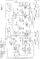
- the system usable current Imit is determined to a value that is greater in the case where the voltage-drop margin value ⁇ V is large than in the case where the voltage-drop margin value ⁇ V is small.
- the system usable current Imit is determined to an upper limit value Imax, and in the case where the voltage-drop margin value ⁇ V is less than or equal to the set value ⁇ Va, the system usable current Imit is determined to a value less than the upper limit value Imax.
- the system usable current Imit is determined to a lowest-performance required current Imin greater than zero.
- the lowest-performance required current Imin is a current required for the braking device 6 to perform minimum operations. If the voltage-drop margin value ⁇ V is small, and the lowest-performance required current Imin is supplied, a voltage applied to the ECUs 8, 94 and so on is in some cases less than or equal to the lowest operation voltage Vlow, leading to a situation in which the ECUs 8, 94 and so on are inoperable. In this case, a manual-operating state is established, and the hydraulic brake 12 is actuated by a hydraulic pressure produced by the master cylinder 26.
- the lowest operation voltage Vlow is determined to a higher one of the lowest operation voltage for the brake ECU 8 and the lowest operation voltage for the motor ECU 94. If the actual lowest operation voltage for the brake ECU 8 is less than the lowest operation voltage for the motor ECU 94, even in the case where the lowest-performance required current Imin is supplied when the voltage-drop margin value ⁇ V is equal to zero, the voltage applied to the brake ECU 8 is greater than the lowest operation voltage for the brake ECU 8 in some cases.
- the system usable current Imit is determined to the lowest-performance required current Imin greater than zero, making it possible for the brake ECU 8 and the motor ECU 94 to control the braking device 6 as possible.
- An electromagnetic-valve requested current is obtained which is the sum of currents requested by a plurality of electromagnetic valves provided in the hydraulic-brake line 13.
- the requested hydraulic pressure Pt is the same between the wheel cylinders 30FL, 30FR as described above
- the sum of currents to be supplied to the solenoids of the master cut-off valves 52L, 52R and the simulator control valve 74 as electromagnetic valves is obtained as the electromagnetic-valve requested current.
- the sum of measured values of the respective currents flowing through these solenoids is determined to the electromagnetic-valve requested current. Strictly, while the sum of the measured values of the respective currents is an electromagnetic-valve operating current, it is possible to consider that the electromagnetic-valve operating current is the electromagnetic-valve requested current in a broad sense.
- the sum of the currents to be supplied to the solenoids of the master cut-off valves 52L, 52R, the simulator control valve 74, the cut-off valves 72L, 72R, and the linear valves 70L, 70R as the electromagnetic valves is obtained as the electromagnetic-valve requested current.
- the currents to be supplied to the solenoids of the respective linear valves 70L, 70R are determined based on the requested hydraulic pressure Pt.
- An ECU-operation requested current is obtained which is the sum of currents required for the brake ECU 8 and the motor ECUs 94RL, 94RR to operate, respectively.
- An electromagnetic-valve-ECU requested current Ibase is obtained which is the sum of the electromagnetic-valve requested current and the ECU-operation requested current.
- a motor usable current Immit usable for the pump motor 56 and the brake motor 86 is obtained based on a value obtained by subtracting the electromagnetic-valve-ECU requested current Ibase from the system usable current Imit.
- a pump-motor usable current ImmitP usable for the pump motor 56 and a brake-motor usable current ImmitB usable for the electric brake 16 are calculated based on the motor usable current Immit.
- the motor usable current Immit may be distributed to the pump-motor usable current ImmitP and the brake-motor usable current ImmitB based on a ratio between the requested hydraulic braking force and the requested electric braking force and may be distributed to the pump-motor usable current ImmitP and the brake-motor usable current ImmitB at a predetermined ratio, for example. It is noted that the pump motor 56 and the brake motor 86 may be configured such that operations of the pump motor 56 and the brake motor 86 are not started at the same time.
- a maximum allowable duty ratio DmaxP at which a current is suppliable to the pump motor 56 is obtained based on the pump-motor usable current ImmitP.
- a maximum allowable duty ratio DmaxB at which a current is suppliable to the brake motor 86 is obtained based on the brake-motor usable current ImmitB.
- An actual hydraulic pressure P in the wheel cylinder 30 and an actual load F applied to the pressing member 88 of the electric brake 16 are measured.
- Requested operating states are obtained to bring the actual hydraulic pressure P and the actual load F closer to the requested hydraulic pressure Pt and the requested load Ft, respectively.
- the requested operating states are operating states requested respectively for the pump motor 56 and the brake motor 86.
- Requested duty ratios are obtained to establish the requested operating states of the pump motor 56 and the brake motor 86.
- the requested duty ratios are duty ratios of supply currents which are requested respectively for the pump motor 56 and the brake motor 86.
- a supply liquid amount requested for the actual hydraulic pressure Ps to be brought closer to the requested hydraulic pressure Pt is obtained, and a requested pump-motor rotation speed NtP which is a rotation speed of the pump motor 56 is obtained as the requested operating state.
- an amount of forward movement which is requested for the actual load Fs to be brought closer to the requested load Ft is obtained as the requested operating state.
- a requested duty ratio DtP that is a duty ratio of a supply current requested by the pump motor 56 is obtained based on an actual rotation speed NsP of the pump motor 56 and the requested pump-motor rotation speed NtP.
- a requested duty ratio DtB that is a duty ratio of a supply current requested by the brake motor 86 is obtained based on an actual rotation speed NsB of the brake motor 86 and the requested brake-motor rotation speed NtB.
- the requested duty ratios DtP, DtB and the maximum allowable duty ratios DmaxP, DmaxB are compared with each other, respectively.
- a control duty ratio DP* that is a duty ratio of a current to be supplied to the pump motor 56 is determined to the requested duty ratio DtP.
- a current of the requested duty ratio DtP is supplied, it is difficult for the voltage applied to the brake ECU 8 and the motor ECU 94 to be less than the lowest operation voltage due to the voltage drop caused due to operation of the pump motor 56.
- the duty ratio DP* for control of the pump motor 56 is determined to a value less than the requested duty ratio DtP, e.g., the maximum allowable duty ratio DmaxP. This is because, in the case where the current of the requested duty ratio DtP is supplied to the pump motor 56, there is a possibility that the voltage applied to the brake ECU 8 and the motor ECU 94 becomes less than the lowest operation voltage by a voltage drop caused due to operation of the pump motor 56.
- Similar processings are executed for the brake motor 86. That is, the requested duty ratio DtB and the maximum allowable duty ratio DmaxB are compared with each other, and a control duty ratio DB* is determined to the requested duty ratio DtB or the maximum allowable duty ratio DmaxB.
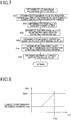
- the flowchart in Fig. 5 represents one example of an actuator control program.
- the present program is executed each time when a set length of time is elapsed.
- it is determined, based on, e.g., the voltage of the main power source 120 which is detected by the main voltage sensor 107, whether the vehicle brake system is in a state in which electric power is supplied from the main power source 120 to the braking device 6, the ECUs 8, 94, and so on. It is determined at S2 whether the brake request is issued.
- a positive decision (YES) is made at S1 or when negative decisions (NO) are made at S1 and S2
- processings at S3 and subsequent steps are not executed.
- the requested total braking force is obtained at S3 based on the brake request as described above.
- the requested duty ratios are obtained for the pump motor 56 and the brake motor 86, respectively.
- the maximum allowable duty ratios are obtained for the pump motor 56 and the brake motor 86, respectively.
- the requested duty ratios at S4 there will be described obtainment of the requested duty ratios at S4 with reference to the flowchart in Fig. 6 .
- the actual hydraulic pressure Ps in the wheel cylinder 30 and the actual rotation speed NsP of the pump motor 56 are detected by the wheel-cylinder-pressure sensor 104 and the pump-motor-rotation-speed sensor 108, respectively, and the actual load Fs of the electric brake 16 and the actual rotation speed NsB of the brake motor 86 are detected by the load sensor 112 and the brake-motor-rotation-speed sensor 110, respectively.
- the requested hydraulic braking force and the requested electric braking force are obtained based on the requested total braking force, and the requested hydraulic pressure Pt and the requested load Ft are obtained.
- the requested pump-motor rotation speed NtP as the requested operating state of the pump motor 56 is obtained based on the actual hydraulic pressure Ps in the wheel cylinder 30, the hydraulic-pressure deviation ⁇ P, and so on.
- the requested brake-motor rotation speed NtB is obtained based on the actual load Fs, the load deviation ⁇ F, and so on.
- the requested duty ratios DtP, DtB respectively for the pump motor 56 and the brake motor 86 are obtained based on the rotation-speed deviations ⁇ NP, ⁇ NB.
- the electromagnetic-valve-ECU requested current Ibase is obtained.
- the voltage Vbat of the auxiliary power source 122 is detected by the auxiliary voltage sensor 106. Since there is a malfunction in the main power source 120, the voltage Vbat of the auxiliary power source 122 is obtained as the voltage of the vehicle-mounted power source 4.
- the voltage-drop margin value ⁇ V is obtained by subtracting the lowest operation voltage Vlow from the voltage Vbat.
- the system usable current Imit is obtained based on the voltage-drop margin value ⁇ V according to the map in Fig. 8 .
- the motor usable current Immit is obtained by subtracting the electromagnetic-valve-ECU requested current Ibase from the system usable current Imit.
- the pump-motor usable current ImmitP and the brake-motor usable current ImmitB are obtained based on the motor usable current Immit.
- the maximum allowable duty ratios DmaxP, DmaxB respectively for the pump motor 56 and the brake motor 86 are obtained based on the pump-motor usable current ImmitP and the brake-motor usable current ImmitB.
- Processings at S6 and subsequent steps are executed thereafter.
- the processings at S6-S8 are executed for each of the pump motor 56 and the brake motor 86, but the flowchart in Fig. 5 represents processings for both of the pump motor 56 and the brake motor 86 for simplicity.
- the pump motor 56 and the plurality of electromagnetic valves are controlled, and information such as the control duty ratio DB* for the brake motor 86 is output to the motor ECU 94.
- Currents of the control duty ratios DP*, DB* are supplied to the pump motor 56 and the brake motor 86, respectively.
- Fig. 9 represents changes of the voltage Vbat of the auxiliary power source 122 and an ECU voltage Ve as a voltage applied to the brake ECU 8 in the case where no current is supplied from the main power source 120 to the braking device 6, the ECUs 8, 94, and the auxiliary power source 122 due to a malfunction in the main power source 120 and in the case where the requested hydraulic braking force is greater than zero, and the requested electric braking force is equal to zero.
- the voltage Vbat of the auxiliary power source 122 decreases with increase in the number of operations of the brake.
- an inrush current at the second or third start of operation of the pump motor 56 in some cases makes the ECU voltage Ve transiently less than the lowest operation voltage Vlow, which may make the brake ECU 8 inoperable.
- the control duty ratio DP* for the pump motor 56 is made less than the requested duty ratio DtP to reduce the inrush current.
- the control duty ratio DP* is made less than the requested duty ratio DtP to reduce both of the inrush current and a current in the steady state.
- each of the master cut-off valves 52L, 52R, the simulator control valve 74, the cut-off valves 72L, 72R, the linear valves 70L, 70R, and so on is one example of a first actuator.
- Each of the pump motor 56 and the brake motor 86 is one example of a second actuator.
- Portions of the brake ECU 8 which store and execute the actuator control program constitute the actuator controller and a vehicle-mounted-device controller, for example.
- Portions of the brake ECU 8 which store and execute the processing at S53 in the actuator control program constitute a voltage-drop-margin-value obtainer, for example.
- Portions of the brake ECU 8 which store and execute the processing at S54 constitute a usable-current obtainer and a system-usable-current obtainer, for example.
- Portions of the brake ECU 8 which store and execute a portion of the processing at S51 which obtains the electromagnetic-valve requested current constitute a total-first-requested-current obtainer, for example.
- Portions of the brake ECU 8 which store and execute the processing at S55 constitute a second usable-current obtainer, for example.
- Portions of the brake ECU 8 which store and execute the processing at S56 constitute a maximum-allowable-duty-ratio obtainer, for example.
- Portions of the brake ECU 8 which store and execute the processing at S46 constitute a second requested-current obtainer, a requested-duty-ratio obtainer, and a second-operation-start-requested-current obtainer, for example.
- Portions of the brake ECU 8 which store and execute the processings at S6-S8 constitute an operation restrictor, an inrush-current restrictor, and a duty-ratio restrictor, for example.
- Portions of the brake ECU 8 which store and execute the processing at S1 constitute a main-power-supply-state obtainer, for example.
- a second usable current corresponds to the maximum allowable duty ratio.
- Each of a second requested current and a second operation-start requested current correspond to the requested duty ratios.
- the sum of first requested currents correspond to the electromagnetic-valve requested current.
- the usable current may be referred to as the system usable current.
- the present disclosure may be applied to a vehicle brake system illustrated in Fig. 10 .
- the present vehicle brake system includes a braking device 200, a brake ECU 202, and the vehicle-mounted power source 4.
- the braking device 200 has front and rear lines, specifically, the braking device 200 has: a front-wheel brake line 215 connected to one of two pressure chambers of a master cylinder 212 and including hydraulic brakes 214FL, 214FR provided for the respective front left and right wheels; and a rear-wheel brake line 217 connected to the other of the two pressure chambers and including hydraulic brakes 216RL, 216RR provided for the respective rear left and right wheels.
- the same hydraulic pressure related to an operation of a brake pedal 210 is produced in the two pressure chambers of the master cylinder 212.
- the front-wheel brake line 215 includes: a master passage 221F connecting between the one of the pressure chambers of the master cylinder 212 and each of wheel cylinders 220FL, 220FR for the respective hydraulic brakes 214FL, 214FR; a master cut-off valve 223F and a pressure-differential control valve 222F that are normally-open electromagnetic valves provided in the master passage 221F in series; a pump passage 226F connecting between a pressure reduction reservoir 224F and a portion of the master passage 221F which is located downstream of the pressure-differential control valve 222F; a pump unit 228F provided in the pump passage 226F; a reservoir passage 229F connecting between a master reservoir 212r and a portion of the master passage 221F which is located between the master cut-off valve 223F and a pressure-differential control valve 220F; and a communication control valve 231F that is a normally-closed electromagnetic valve provided in the reservoir passage 229F.
- Pressure holding valves 230FL, 230FR that are normally-open electromagnetic valves corresponding to the respective wheel cylinders 220FL, 220FR are provided at positions located downstream of a portion of the master passage 221F to which the pump passage 226F is connected.
- Normally-closed electromagnetic valves in the form of pressure reduction valves 234FL, 234FR are provided in a pressure reduction passage 232F connecting between the pressure reduction reservoir 224F and each of the wheel cylinders 220FL, 220FR.
- the pressure reduction reservoir 224F includes a working-liquid storage chamber 240F and a replenishment valve 242F.
- the pressure reduction passage 232F is connected to the working-liquid storage chamber 240F, and a replenishment passage 244F is connected to the replenishment valve 242F.
- the replenishment passage 244F is connected to a portion of the master passage 221F which is located between the pressure-differential control valve 222F and the master cut-off valve 223F (the portion of the master passage 221F which is located downstream of a portion of the master passage 221F to which the reservoir passage 229F is connected in the present embodiment).
- the replenishment valve 242F is in a closed state in the case where an amount of the working liquid stored in the working-liquid storage chamber 240F is greater than a set liquid amount.
- the replenishment valve 242F is switched to an open state.
- the working liquid in the master reservoir 212r is supplied to the working-liquid storage chamber 240F via the replenishment passage 244F.
- Each of the pressure holding valves 230FL, 230FR is configured to continuously control a pressure differential between (i) a hydraulic pressure on an upstream side of each of the pressure holding valves 230FL, 230FR (on a side of each of the pressure holding valves 230FL, 230FR on which the pump passage 226F is connected to the master passage 221F) and (ii) a hydraulic pressure on a downstream side of each of the pressure holding valves 230FL, 230FR (on a side of each of the pressure holding valves 230FL, 230FR on which a corresponding one of the wheel cylinders 220FL, 220FR is provided).
- the pressure differential that is a value obtained by subtracting the hydraulic pressure on the downstream side from the hydraulic pressure on the upstream side is controlled to a value related to currents supplied to the solenoids of the pressure holding valves 230FL, 230FR.
- the pressure differential is controlled by control of a current supplied to the solenoid of a corresponding one of the pressure holding valves 230.
- the pressure-differential control valve 222F is configured to continuously control a pressure differential between a hydraulic pressure on an upstream side of the pressure-differential control valve 222F and a hydraulic pressure on a downstream side of the pressure-differential control valve 222F.
- the pressure differential that is a value obtained by subtracting the hydraulic pressure on the upstream side (the hydraulic pressure on a side of the pressure-differential control valve 222F on which the master reservoir 212r is provided) from the hydraulic pressure on the downstream side (the hydraulic pressure at a portion of the master passage 221F to which the pump passage 226F is connected) is controlled to a value related to a current supplied to the solenoid of the pressure-differential control valve 222F.
- the pressure-differential control valve 222F controls the discharge pressure of the pump unit 228F, thereby controlling the hydraulic pressure in the wheel cylinder 220.
- the pump unit 228F includes a pump 250F and a pump motor 252 configured to drive the pump 250F.
- the pump motor 252 is shared between the pump unit 228F and a pump unit 228R provided in the rear-wheel brake line 217.
- a stroke simulator 260 is connected to the master passage 221F via a normally-closed electromagnetic valve in the form of a simulator control valve 262.
- the stroke simulator 260 is not provided in the rear-wheel brake line 217.
- the brake ECU 202 is principally constituted by a computer and includes an executing device, a storage, and an input/output device, not illustrated.
- Devices connected to the brake ECU 202 include: a stroke sensor 270 configured to detect a stroke of the brake pedal 210; master-cylinder-pressure sensors 272F, 272R configured to detect the hydraulic pressures in the respective pressure chambers of the master cylinder 212; wheel-cylinder-pressure sensors 274FL, 274FR, 274RL, 274RR configured to detect the hydraulic pressures in the respective wheel cylinders 220; the auxiliary voltage sensor 106 configured to detect the voltage of the auxiliary power source 122; the main voltage sensor 107 configured to detect the voltage of the main power source 120; and a rotation-speed sensor 280 configured to detect a rotation speed of the pump motor 252.
- the pump motor 252 is connected to the brake ECU 202 via a drive circuit, not illustrated.
- the solenoids of the plurality of electromagnetic valves e.g., the master cut-off valves 223, the pressure-differential control valves 222, the pressure holding valves 230, the simulator control valve 262, and the communication control valves 231) are connected to the brake ECU 202, for example.
- Electric power is supplied from the vehicle-mounted power source 4 to the braking device 200 and the brake ECU 202.
- the vehicle-mounted power source 4 is similar to the vehicle-mounted power source in the above-described embodiment.
- the pump motor 252 and the pressure-differential control valves 222F, 222R are controlled to control the hydraulic pressures in the respective wheel cylinders 220 to the same magnitude.
- the electromagnetic-valve requested current is obtained based on, e.g., currents supplied to the solenoids of the communication control valves 231F, 231R, the master cut-off valves 223F, 223R, the pressure-differential control valves 222F, 222R, and the simulator control valve 262, for example.
- the hydraulic pressure of the working liquid discharged from each of the pumps 250 is controlled by a corresponding one of the pressure-differential control valves 222 and supplied to corresponding ones of the wheel cylinders 220.
- the current to be supplied to the solenoid of each of the pressure holding valves 230 is determined based on a difference between a hydraulic pressure obtained by controlling the discharge pressure of a corresponding one of the pumps 250 by a corresponding one of the pressure-differential control valves 222 and the requested hydraulic pressure Pt for a corresponding one of the wheel cylinders 220, but in the case where the discharge pressures of the respective pumps 250 (strictly, the hydraulic pressures controlled by the respective pressure-differential control valves 222) are substantially equal to each other, it is possible to consider that the currents to be supplied to the solenoids of the respective pressure holding valves 230 are determined based on the requested hydraulic pressures Pt for the respective wheel cylinder 220.
- the electromagnetic-valve requested current is obtained based on (i) currents to be supplied to the solenoids of the communication control valves 231F, 231R, the master cut-off valves 223F, 223R, the pressure-differential control valves 222F, 222R, the simulator control valve 262, and so on and (ii) currents requested by the pressure holding valves 230.
- the present disclosure may be applied to a vehicle brake system illustrated in Fig. 11 .
- the present brake system includes a braking device 300, a brake ECU 302, and the vehicle-mounted power source 4.
- the braking device 300 includes: a master cylinder 314 configured to produce a hydraulic pressure related to an operation of a brake pedal 312; a stroke simulator 316 connected to the master cylinder 314; wheel cylinders 320 provided for hydraulic brakes 318 provided for the respective front left and right and rear left and right wheels; and a hydraulic-pressure control unit 322 provided between the wheel cylinders 320 and the master cylinder 314.
- the braking device 300 has an X-type two lines, specifically, the braking device 300 has: a brake line 323a including the hydraulic brakes 318FL provided for the front left wheel and the hydraulic brakes 318RR provided for the rear right wheel; and a brake line 323b including the hydraulic brake 318FR provided for the front right wheel and the hydraulic brake 318RL provided for the rear left wheel.
- the hydraulic-pressure control unit 322 includes master cut-off valves 326a, 326b provided respectively on main passages 324a, 324b each connecting between the master cylinder 314 and each of corresponding ones of the wheel cylinders 320; a common passage 334 to which the main passages 324a, 324b, individual passages 328 connected to the respective wheel cylinders 320, and a pump passage 330 are connected; a pump unit 338 provided in the pump passage 330; pressure holding valves 340 that are normally-open electromagnetic valves provided in the respective individual passages 328; pressure reduction valves 344 that are normally-closed electromagnetic valves each provided between a master reservoir 342 and a corresponding one of the wheel cylinders 320; a simulator control valve 346 that is a normally-closed electromagnetic valve provided between the stroke simulator 316 and the master reservoir 342; and an electromagnetic valve 348 provided between the stroke simulator 316 and the common passage 334.
- the pump unit 338 includes a pump 350 and a pump motor 352.
- the pump passage 330 is connected to the common passage 334 at a position located between (i) portions of the common passage 334 to which the individual passages 328FR, 328RL in the brake line 323b are respectively connected and (ii) portions of the common passage 334 to which the individual passages 328FL, 328RR in the brake line 323a are respectively connected.
- the pump passage 330 and the master reservoir 342 are connected to each other by a control passage 360.
- a normally-closed electromagnetic valve in the form of a discharge-pressure control valve 362 is provided in the control passage 360.
- a normally-closed electromagnetic valve in the form of a communication valve 372 is provided in the common passage 334 at a position located between (i) portions of the common passage 334 to which the individual passages 328FL, 328RR in the brake line 323a are connected and (ii) a portion of the common passage 334 to which the pump passage 330 and the control passage 360 are connected.
- a normally-closed electromagnetic valve in the form of a communication valve 374 is provided in the common passage 334 at a position located between (i) portions of the common passage 334 to which the individual passages 328FR, 328RL in the brake line 323b are connected and (ii) the portion of the common passage 334 to which the pump passage 330 and the control passage 360 are connected.
- the brake ECU 302 is principally constituted by a computer.
- Devices connected to the brake ECU 302 include: a stroke sensor 380 configured to detect a stroke of the brake pedal 312; a master-cylinder-pressure sensor 382 configured to detect a hydraulic pressure in the master cylinder; common hydraulic-pressure sensors 384, 386 each configured to detect a hydraulic pressure in the common passage 334; a discharge-pressure sensor 388 configured to detect a discharge pressure of the pump 350; the auxiliary voltage sensor 106 configured to detect electric power of the auxiliary power source 122; the main voltage sensor 107 configured to detect the voltage of the main power source 120; a rotation-speed sensor 390 configured to detect a rotation speed of the pump motor 352; a drive circuit of the pump motor 352; and the solenoids of the electromagnetic valves such as the master cut-off valves 326a, 326b, the pressure holding valves 340, the discharge-pressure control valve 362, the simulator control valve 346, and the communication valves 372, 374.
- the currents are supplied to the solenoids of the master cut-off valves 326a, 326b, the simulator control valve 346, and the communication valves 372, 374 to close the master cut-off valves 326a, 326b, open the simulator control valve 346, and open the communication valves 372, 374.
- the pump motor 352 is controlled to actuate the pump 350, so that the hydraulic pressure of the working liquid discharged from the pump 350 is supplied to the wheel cylinders 320 provided for the respective front left and right and rear left and right wheels.
- the hydraulic pressures in the respective wheel cylinders 320 are controlled together by control of at least one of the pump motor 352 and the discharge-pressure control valve 362.
- currents to be supplied to the solenoids of the respective pressure holding valves 340 are controlled to individually control the hydraulic pressures in the respective wheel cylinders 320 using the hydraulic pressure of the working liquid discharged from the pump 350.
- the electromagnetic-valve requested current is obtained based on currents requested by the master cut-off valves 326a, 326b, the simulator control valve 346, the communication valves 372, 374, and the discharge-pressure control valve 362 or obtained based on currents requested by the master cut-off valves 326a, 326b, the simulator control valve 346, the communication valves 372, 374, the pressure holding valves 340, and so on, for example.
- the system usable current Imit is calculated based on a value obtained by subtracting a lowest operation voltage Vlow required for operations of the brake ECU 302, from the voltage Vbat of the auxiliary power source 122.
- the motor usable current Immit is obtained based on a value obtained by subtracting the electromagnetic-valve-ECU requested current Ibase from the system usable current Imit.
- the motor usable current Immit is determined to the pump-motor usable current ImmitP.
- the control duty ratio DP* that is a duty ratio of a current to be actually supplied to the pump motor 336 is limited to a value less than or equal to the maximum allowable duty ratio, thereby reducing the inrush current. This makes it difficult to establish a state in which the brake ECU 302 is inoperable.
- the vehicle brake system may have any configuration.
- the present disclosure may be applied to a brake system in which electric brakes are provided respectively for the front left and right and rear left and right wheels.
- the motor usable current Immit is determined to the brake-motor usable current ImmitB.
- the present disclosure may be applied to a brake system including a mechanism in which a motion converter 404 converts rotation of an output shaft 402 of an assist electric motor 400 to straight movement of a pressing member 406, and the pressing member 406 is moved forward to move a pressurizing piston 408 forward to produce a hydraulic pressure in a pressure chamber 412 of a master cylinder 410.
- the motor usable current Immit is determined to a current usable by the assist electric motor 400.
- An object to which the present disclosure is applied is not limited to the vehicle brake system and may be a steering system, for example.
- the steering system includes an assist motor as an actuator for assisting a steering torque. That is, a technique according to the present disclosure can be achieved in the case where an auxiliary power source is shared between electric motors or the like having different functions, such as a brake system and a steering system.
- the technique according to the present disclosure may be implemented in a state in which electric power is suppliable from the main power source 120 to the braking device, the ECUs, and so on. It is to be understood that the disclosure is not limited to the details of the illustrated embodiments, but may be embodied with various changes and modifications, which may occur to those skilled in the art, without departing from the spirit and scope of the disclosure. For example a method of obtaining the requested duty ratio is not limited to the method in the above-described embodiment.
- Each of the one or more electromagnetic valves corresponds to the first actuator, and the vehicle-installed system corresponds to the vehicle brake system.
- the one or more electromagnetic valves include at least one of an open/close valve and a linear valve.
- the electromagnetic valve is an open/close valve
- the first requested operating state as the requested operating state of the electromagnetic valve may be represented by establishing an open state or a closed state.
- the electromagnetic valve is a linear valve
- the first requested operating state as the requested operating state of the electromagnetic valve may be represented by bringing a hydraulic pressure in the valve closer to the requested hydraulic pressure.
- a current requested for establishing the first requested operating state in the electromagnetic valve is the first requested current.
- the first requested current for the linear valve is usually determined based on the requested hydraulic pressure.
- the hydraulic-pressure source may be any of a manual hydraulic-pressure source and a power-operated hydraulic pressure source.
- a manual hydraulic-pressure source is a master cylinder configured to produce a hydraulic pressure related to an operation of a brake operating member.
- the power-operated hydraulic pressure source include a pump and an accumulator.
Landscapes
- Engineering & Computer Science (AREA)
- Mechanical Engineering (AREA)
- Transportation (AREA)
- General Engineering & Computer Science (AREA)
- Physics & Mathematics (AREA)
- Fluid Mechanics (AREA)
- Regulating Braking Force (AREA)
- Braking Systems And Boosters (AREA)
- Valves And Accessory Devices For Braking Systems (AREA)
- Safety Devices In Control Systems (AREA)
Abstract
Description
- The following disclosure relates to an actuator controller configured to control an actuator operable by electric power supplied from the vehicle-mounted power source, and to a vehicle-installed system including the actuator controller.
- Patent Document 1 (Japanese Patent Application Publication No.
2009-227093 - Accordingly, an aspect of the disclosure relates to a technique making it difficult to establish a state in which an actuator controller is inoperable due to a voltage drop caused by an operation of an actuator.
- In one aspect of the disclosure, an actuator controller is configured such that an operation of each of at least one of one or more actuators is restricted such that an amount of a voltage drop caused by an operation of one or more actuators does not exceed a voltage-drop margin value that is obtained by subtracting a lowest operation voltage required for an operation of the actuator controller, from a voltage of a vehicle-mounted power source.
- The objects, features, advantages, and technical and industrial significance of the present disclosure will be better understood by reading the following detailed description of the embodiments, when considered in connection with the accompanying drawings, in which:
-
Fig. 1 is a view conceptually illustrating a vehicle brake system including an actuator controller according to a first embodiment; -
Fig. 2 is a cross-sectional view of a hydraulic brake of the vehicle brake system; -
Fig. 3 is a cross-sectional view of an electric brake of the vehicle brake system; -
Fig. 4 is a view conceptually illustrating connection between a vehicle-mounted power source, and each of a brake ECU and a motor ECU of the vehicle brake system; -
Fig. 5 is a flowchart representing an actuator control program stored in a storage of the actuator controller; -
Fig. 6 is a flowchart representing a portion of the actuator control program (for obtaining the target duty ratio); -
Fig. 7 is a flowchart representing another portion of the actuator control program (for obtaining the maximum allowable duty ratio); -
Fig. 8 is a map representing a relationship between a usable current and a voltage-drop margin value and stored in the storage; -
Fig. 9 is a view illustrating one example of a pump motor by the actuator controller; -
Fig. 10 is a view conceptually illustrating a vehicle brake system including an actuator controller according to a second embodiment; -
Fig. 11 is a view conceptually illustrating a vehicle brake system including an actuator controller according to a third embodiment; and -
Fig. 12 is a view conceptually illustrating another vehicle brake system including an actuator controller to which the present disclosure is applied. - Hereinafter, there will be described embodiments of the present disclosure in each of which a vehicle brake system as one example of a vehicle-installed system includes an actuator controller.
- In the first embodiment, as schematically illustrated in
Fig. 1 , a vehicle brake system includes a vehicle-mountedpower source 4, abraking device 6 as one example of a vehicle-mounted device, and abrake ECU 8 configured to control thebraking device 6. Thebraking device 6 includes: a hydraulic-brake line 13 including hydraulic brakes 12FL, 12FR provided respectively for front left and right wheels 10FL, 10FR; and an electric-brake line 17 including electric brakes 16RL, 16RR provided respectively for rear left and right wheels 14RL, 14RR. - The hydraulic-
brake line 13 includes: the hydraulic brakes 12FL, 12FR; amaster cylinder 26 including a pressurizing piston that is operated in response to movement of abrake pedal 24 as one example a brake operating member operable by a driver; and a hydraulic-pressure control unit 32 provided between (i) themaster cylinder 26 and areservoir 28 and (ii) wheel cylinders 30FL, 30FR for the respective hydraulic brakes 12FL, 12FR. - The
master cylinder 26 is of a tandem type in which a hydraulic pressure of a magnitude related to a braking-operation force applied to thebrake pedal 24 is produced in two pressure chambers defined in front of respective two pressurizing pistons.Master passages master cylinder 26. The two pressure chambers are connected to the respective wheel cylinders 30FL, 30FR via therespective master passages - As illustrated in
Fig. 2 , each of thehydraulic brakes 12 is a disc brake as a friction brake. Thishydraulic brake 12 includes: adisc rotor 40 as a brake rotor which is rotated integrally with a corresponding one of the front left and right wheels 10FL, 10FR; acaliper 42 supported by an unrotatable member so as to be movable in a direction parallel with a rotation axis L of the corresponding one of the front left and right wheels 10FL, 10FR; a pair ofbrake pads 44 as a pair of friction engagement members located on opposite sides of thedisc rotor 40; and thewheel cylinder 30 provided inside thecaliper 42. - In the case where a hydraulic pressure is supplied to a hydraulic-
pressure chamber 46 of the wheel cylinder 30 (noted that the hydraulic pressure in the hydraulic-pressure chamber 46 of thewheel cylinder 30 may be hereinafter referred to simply as "hydraulic pressure in thewheel cylinder 30"), the hydraulic pressure moves apiston 48 and thecaliper 42 in the direction parallel with the rotation axis L. Thebrake pads 44 are pressed against thedisc rotor 40 and thereby brought into frictional engagement with thedisc rotor 40. That is, thehydraulic brake 12 is actuated. As a result, a hydraulic braking force related to the hydraulic pressure in thewheel cylinder 30 is applied to each of the front left and right wheels 10FL, 10FR. - The hydraulic-
pressure control unit 32 includes: master cut-offvalves respective master passages pump passage 60L connecting between areservoir passage 28L connected to thereservoir 28 and a portion of themaster passage 38L which is located downstream of the master cut-offvalve 52L; apump passage 60R connecting between thereservoir passage 28L and a portion of themaster passage 38R which is located downstream of the master cut-offvalve 52R; twopumps respective pump passages pump motor 56 configured to drive thepumps electromagnetic valve devices - As illustrated in
Fig. 1 , each of themaster passages master cylinder 26 and a corresponding one of the wheel cylinders 30FL, 30FR to each other without passing through thepumps electromagnetic valve devices pump 54L and the wheel cylinder 30FL are connected to each other by thepump passage 60L and the portion of themaster passage 38L. Thepump 54R and the wheel cylinder 30FR are connected to each other by thepump passage 60R and the portion of themaster passage 38R. - Each of the
pumps reservoir 28 and pressurizes and supplies the working liquid to a corresponding one of the wheel cylinders 30FL, 30FR.Check valves respective pumps respective pumps pumps pump motor 56 is a brushless motor connected to the brake ECU 8 via aninverter 70 as a drive circuit. Thepump motor 56 is controlled by control for theinverter 70 to control operations of thepumps -
Return passages return passages pump passages master passages pumps check valves reservoir passage 28L or a corresponding one of thepump passages pumps electromagnetic valve devices respective return passages electromagnetic valve device 58L includes alinear valve 70L as a normally-open electromagnetic valve and a cut-offvalve 72L as a normally-closed electromagnetic valve which are provided in series. Theelectromagnetic valve device 58R includes alinear valve 70R as a normally-open electromagnetic valve and a cut-offvalve 72R as a normally-closed electromagnetic valve which are provided in series. For example, each of the cut-offvalves reservoir 28 than the corresponding one of thelinear valves linear valves - A
stroke simulator 76 is connected, via asimulator control valve 74 as a normally-closed electromagnetic valve, to a portion of themaster passage 38L which is located upstream of the master cut-offvalve 52L. Operations of thestroke simulator 76 are allowed in an open state of thesimulator control valve 74. - As illustrated in
Fig. 3 , each of the electric brakes 16RL, 16RR provided for the respective rear left and right wheels 14RL, 14RR is a disc brake as a friction brake. Theelectric brake 16 includes adisc rotor 80, acaliper 82, a pair ofbrake pads 84, abrake motor 86 that is an electric motor provided on thecaliper 82, and ascrew mechanism 90 as a motion converting mechanism configured to convert rotation of thebrake motor 86 to straight movement of apressing member 88. Rotation of thebrake motor 86 moves the pressingmember 88 forward in the direction parallel with the rotation axis L, which moves thecaliper 82. As a result, the pair ofbrake pads 84 are pressed against and frictionally engaged with thedisc rotor 80. That is, theelectric brake 16 is actuated to apply an electric braking force to each of the rear left and right wheels 14RL, 14RR. The brake motors 86RL, 86RR are connected to respective motor ECUs 94RL, 94RR via respective drive circuits 92RL, 92RR and controlled by controls of the respective motor ECUs 94RL, 94RR. - As illustrated in
Fig. 4 , the vehicle-mountedpower source 4 supplies electric power to the braking device 6 (including thepump motor 56, the electromagnetic valves, such as the master cut-offvalves brake ECU 8, the motor ECUs 94RL, 94RR, and so on, and includes amain power source 120 and anauxiliary power source 122. As illustrated inFig. 1 , themain power source 120 includes amain battery 124, asubsidiary battery 125, and a DC/DC converter 126. It is noted thatFig. 4 conceptually illustrates a state of connection between the vehicle-mountedpower source 4 and each of thebraking device 6, thebrake ECU 8, and the motor ECUs 94RL, 94RR. In reality, however, thebrake ECU 8, thepump motor 56, the electromagnetic valves, and so on are provided integrally with each other as a unit. Likewise, the motor ECU 94RL and the brake motor 86RL are provided integrally with each other as a unit, and the motor ECU 94RR and the brake motor 86RR are provided integrally with each other as a unit. In each of the units, corresponding ones of thepump motor 56, the electromagnetic valves, thebrake ECU 8, thebrake motors 86, and the motor ECUs 94RL, 94RR are connected to the vehicle-mountedpower source 4 in parallel. - In the case where a drive source, not illustrated, of the vehicle includes an electric motor for driving, the
main battery 124 supplies electric power to the electric motor for driving. Themain battery 124 is charged with electric power generated by a motor generator, not illustrated, in regeneration under braking of the vehicle. In the case where the drive source of the vehicle includes an engine, electric power generated by operation of the engine is supplied to themain battery 124 to charge themain battery 124. Themain battery 124 may be constituted by a storage battery such as a lithium-ion storage battery, for example. Themain battery 124 may be a battery corresponding to a high voltage of 207 V, for example. - The
subsidiary battery 125 may be a lead-acid battery, for example. Thesubsidiary battery 125 may be a battery corresponding to a low voltage of 12 V, for example. The DC/DC converter 126 lowers the high voltage of 207 V supplied from themain battery 124, to a low voltage of 12 V, for example. Thesubsidiary battery 125 is charged with the voltage of 12 V obtained by lowering of the high voltage in the DC/DC converter 126. The voltage of 12 V is also supplied to thebraking device 6, thebrake ECU 8, the motor ECUs 94RL, 94RR, and so on (hereinafter may be referred to as "thebraking device 6, theECUs 8, 94, and so on") via a mainelectric supply line 130. Theauxiliary power source 122 is connected to the DC/DC converter 126 via an electric-chargeelectric supply line 131. Theauxiliary power source 122 includes acapacitor 136. Electric power is supplied from themain power source 120 to thecapacitor 136 via the electric-chargeelectric supply line 131. In the event of failure in themain power source 120, for example, the electric power is supplied from theauxiliary power source 122 to thebraking device 6, theECUs 8, 94, and so on via an auxiliaryelectric supply line 137. - As illustrated in
Fig. 1 , each of thebrake ECU 8 and the motor ECUs 94RL, 94RR is principally constituted by a computer and includes an executingdevice 8c, astorage 8m, and an input/output device 8i. It is noted that illustration of the executing device and so on of the motor ECU 94 is omitted. Thebrake ECU 8 and each of the motor ECUs 94RL, 94RR are communicable with each other. - Devices connected to the input/output device of the
brake ECU 8 include: astroke sensor 100 configured to detect a stroke of thebrake pedal 24; master-cylinder-pressure sensors master cylinder 26; wheel-cylinder-pressure sensors auxiliary voltage sensor 106 as one example of a source-voltage obtainer configured to detect a voltage of theauxiliary power source 122; amain voltage sensor 107 configured to detect a voltage of themain power source 120; a pump-motor-rotation-speed sensor 108 configured to detect a rotation speed of thepump motor 56; and the hydraulic-pressure control unit 32. In the present embodiment, themain voltage sensor 107 detects a voltage of thesubsidiary battery 125. - Devices connected to the input/output device of the motor ECU 94 include: a brake-motor-rotation-speed sensor (a resolver) 110 configured to detect a rotation speed of the
brake motor 86; aload sensor 112 configured to detect a load which is an axial-direction force applied to the pressingmember 88; and the drive circuits 92RL, 92RR for the respective brake motors 86RL, 86RR. - There will be next described operations of the brake system configured as described above. A brake request is output in the case where the
brake pedal 24 is depressed, for example. Thebrake ECU 8 obtains an operation state of the brake pedal 24 (hereinafter may be referred to as "braking-operation state") based on at least one of a value detected by thestroke sensor 100 and values detected by the master-cylinder-pressure sensors brake ECU 8 based on the braking-operation state calculates a requested total braking force that is requested by the driver. In other words, when thebrake pedal 24 is depressed, the brake request is output, and the requested total braking force is calculated based on the brake request. In autonomous vehicles, a brake request is output based on environments around an own vehicle, and a requested total braking force is calculated based on the brake request, i.e., the environments around the own vehicle. - For example, in the case where the drive source of the vehicle includes an electric motor, and a regenerative braking force is applied to the drive wheel, a requested electric braking force and a requested hydraulic braking force are obtained so as to satisfy the requested total braking force by at least one of the regenerative braking force, an electric braking force, and a hydraulic braking force, and a requested load Ft and a requested hydraulic pressure Pt are calculated based on the requested electric braking force and the requested hydraulic braking force. In contrast, in the case where no regenerative braking force is applied to the drive wheel (e.g., the case where the vehicle does not include an electric motor serving as a drive source or the case where the vehicle includes the electric motor serving as the drive source, but no regenerative braking force is applied), the requested load Ft, the requested hydraulic pressure Pt, and so on are calculated such that the requested total braking force is satisfied by at least one of the electric braking force and the hydraulic braking force. Thus, there are three cases for the requested electric braking force and the requested hydraulic braking force: the case where each of the requested electric braking force and the requested hydraulic braking force is determined to a value greater than zero; the case where one of the requested electric braking force and the requested hydraulic braking force is determined to zero; and the case where each of the requested electric braking force and the requested hydraulic braking force is determined to zero.
- The
brake ECU 8 directly controls the hydraulic-pressure control unit 32 and outputs information relating to control of thebrake motor 86, to the motor ECUs 94RL, 94RR. In the case where the requested hydraulic pressure Pt is the same between the wheel cylinders 30FL, 30FR for the respective front left and right wheels 10FL, 10FR, the hydraulic-pressure control unit 32 supplies currents to solenoids of the master cut-offvalves simulator control valve 74 to close the master cut-offvalves simulator control valve 74. In this state, thepumps pump motor 56. The hydraulic pressure of the same magnitude is supplied to the wheel cylinders 30FL, 30FR. The hydraulic pressures in the respective wheel cylinders 30FL, 30FR are controlled by control of thepump motor 56. In this case, no current is usually supplied to theelectromagnetic valve devices - In the case where the requested hydraulic pressure Pt is different between the wheel cylinders 30FL, 30FR in, e.g., anti-lock control, in contrast, the hydraulic-
pressure control unit 32 supplies currents to the solenoids of the master cut-offvalves simulator control valve 74 to close the master cut-offvalves simulator control valve 74. In this state, thepumps pump motor 56. Furthermore, the hydraulic-pressure control unit 32 supplies currents to solenoids of the cut-offvalves valves linear valves linear valves pumps electromagnetic valve devices - In the event of a malfunction in which no electric power is supplied from the
main power source 120 to thebraking device 6, theECUs 8, 94, and so on, for example, when the voltage of themain power source 120 becomes less than a predetermined malfunction determination voltage, electric power of themain power source 120 is not supplied to thebraking device 6, theECUs 8, 94, and so on, and theauxiliary power source 122. In the event of a malfunction such as a break in the mainelectric supply line 130, electric power of themain power source 120 is supplied to theauxiliary power source 122 but is not supplied to thebraking device 6, theECUs 8, 94, and so on. In these cases, electric power is supplied from theauxiliary power source 122 to thebraking device 6, theECUs 8, 94, and so on. In the latter case, electric power is supplied from themain power source 120 to theauxiliary power source 122 via the electric-chargeelectric supply line 131 to charge thecapacitor 136, but the speed of the charge is slow, so that the voltage of theauxiliary power source 122 lowers with operation of thebraking device 6. - As illustrated in
Fig. 4 , a voltage obtained by subtracting a magnitude corresponding to a voltage drop in a wire from a voltage Vbat of theauxiliary power source 122 is applied to thebrake ECU 8 and the motor ECUs 94RL, 94RR. The magnitude corresponding to the voltage drop in the wire is calculated by multiplying a flowing current I by a well-known resistance R (IR). Thus, in the case where an inrush current flows in each of thepump motor 56 and thebrake motor 86, the magnitude corresponding to the voltage drop increases transiently, so that the voltage applied to thebrake ECU 8 and the motor ECUs 94RL, 94RR lowers transiently. In the case where the voltage applied to thebrake ECU 8 and the motor ECUs 94RL, 94RR is less than a lowest operation voltage Vlow that is a voltage required for operations of thebrake ECU 8 and the motor ECUs 94RL, 94RR, there is a possibility that thebrake ECU 8 and the motor ECUs 94RL, 94RR become inoperable, making it impossible to control thebraking device 6. It is noted that the lowest operation voltage for thebrake ECU 8 and the motor ECUs 94RL, 94RR connected to the vehicle-mountedpower source 4 is determined to a higher one of the lowest voltage required for an operation of thebrake ECU 8 and the lowest voltage required for operations of the motor ECUs 94RL, 94RR. - To solve the problem, the present embodiment makes it difficult to establish a state in which the
brake ECU 8 and the motor ECUs 94RL, 94RR become inoperable due to operations of thepump motor 56, thebrake motor 86, and/or the like. Also, operations of thepump motor 56 and thebrake motor 86 are restricted such that a voltage drop caused due to operations of thepump motor 56 and/or thebrake motor 86 does not exceed a value (a voltage-drop margin value) ΔV obtained by subtracting the lowest operation voltage Vlow for thebrake ECU 8 and the motor ECUs 94RL, 94RR from the voltage Vbat of theauxiliary power source 122. - Specifically, the voltage-drop margin value ΔV is obtained by subtracting the lowest operation voltage Vlow from the voltage Vbat of the
auxiliary power source 122. A usable current (that may be referred to as "system usable current") Imit suppliable from theauxiliary power source 122 to thebraking device 6 and theECUs 8, 94, and so on and usable for thebraking device 6 and theECUs 8, 94, and so on is obtained based on the voltage-drop margin value ΔV. According to the map inFig. 8 , the system usable current Imit is determined to a value that is greater in the case where the voltage-drop margin value ΔV is large than in the case where the voltage-drop margin value ΔV is small. Specifically, in the case where the voltage-drop margin value ΔV is greater than a set value ΔVa, the system usable current Imit is determined to an upper limit value Imax, and in the case where the voltage-drop margin value ΔV is less than or equal to the set value ΔVa, the system usable current Imit is determined to a value less than the upper limit value Imax. - It is noted that, even in the case where the voltage-drop margin value ΔV is equal to zero, the system usable current Imit is determined to a lowest-performance required current Imin greater than zero. The lowest-performance required current Imin is a current required for the
braking device 6 to perform minimum operations. If the voltage-drop margin value ΔV is small, and the lowest-performance required current Imin is supplied, a voltage applied to theECUs 8, 94 and so on is in some cases less than or equal to the lowest operation voltage Vlow, leading to a situation in which theECUs 8, 94 and so on are inoperable. In this case, a manual-operating state is established, and thehydraulic brake 12 is actuated by a hydraulic pressure produced by themaster cylinder 26. - In the case where a plurality of ECUs, such as the
brake ECU 8 and the motor ECU 94, are connected to the vehicle-mountedpower source 4, as described above, the lowest operation voltage Vlow is determined to a higher one of the lowest operation voltage for thebrake ECU 8 and the lowest operation voltage for the motor ECU 94. If the actual lowest operation voltage for thebrake ECU 8 is less than the lowest operation voltage for the motor ECU 94, even in the case where the lowest-performance required current Imin is supplied when the voltage-drop margin value ΔV is equal to zero, the voltage applied to thebrake ECU 8 is greater than the lowest operation voltage for thebrake ECU 8 in some cases. In view of the above, in the case where the voltage-drop margin value ΔV is equal to zero, the system usable current Imit is determined to the lowest-performance required current Imin greater than zero, making it possible for thebrake ECU 8 and the motor ECU 94 to control thebraking device 6 as possible. - An electromagnetic-valve requested current is obtained which is the sum of currents requested by a plurality of electromagnetic valves provided in the hydraulic-
brake line 13. In the case where the requested hydraulic pressure Pt is the same between the wheel cylinders 30FL, 30FR as described above, the sum of currents to be supplied to the solenoids of the master cut-offvalves simulator control valve 74 as electromagnetic valves is obtained as the electromagnetic-valve requested current. In the case where currents are always supplied to the solenoids of the master cut-offvalves simulator control valve 74, the sum of measured values of the respective currents flowing through these solenoids is determined to the electromagnetic-valve requested current. Strictly, while the sum of the measured values of the respective currents is an electromagnetic-valve operating current, it is possible to consider that the electromagnetic-valve operating current is the electromagnetic-valve requested current in a broad sense. - In the case where the requested hydraulic pressure Pt is different between the wheel cylinders 30FL, 30FR, the sum of the currents to be supplied to the solenoids of the master cut-off
valves simulator control valve 74, the cut-offvalves linear valves linear valves - An ECU-operation requested current is obtained which is the sum of currents required for the
brake ECU 8 and the motor ECUs 94RL, 94RR to operate, respectively. An electromagnetic-valve-ECU requested current Ibase is obtained which is the sum of the electromagnetic-valve requested current and the ECU-operation requested current. - A motor usable current Immit usable for the
pump motor 56 and thebrake motor 86 is obtained based on a value obtained by subtracting the electromagnetic-valve-ECU requested current Ibase from the system usable current Imit. A pump-motor usable current ImmitP usable for thepump motor 56 and a brake-motor usable current ImmitB usable for theelectric brake 16 are calculated based on the motor usable current Immit. - The motor usable current Immit may be distributed to the pump-motor usable current ImmitP and the brake-motor usable current ImmitB based on a ratio between the requested hydraulic braking force and the requested electric braking force and may be distributed to the pump-motor usable current ImmitP and the brake-motor usable current ImmitB at a predetermined ratio, for example. It is noted that the
pump motor 56 and thebrake motor 86 may be configured such that operations of thepump motor 56 and thebrake motor 86 are not started at the same time. - A maximum allowable duty ratio DmaxP at which a current is suppliable to the
pump motor 56 is obtained based on the pump-motor usable current ImmitP. A maximum allowable duty ratio DmaxB at which a current is suppliable to thebrake motor 86 is obtained based on the brake-motor usable current ImmitB. - An actual hydraulic pressure P in the
wheel cylinder 30 and an actual load F applied to the pressingmember 88 of theelectric brake 16 are measured. Requested operating states are obtained to bring the actual hydraulic pressure P and the actual load F closer to the requested hydraulic pressure Pt and the requested load Ft, respectively. The requested operating states are operating states requested respectively for thepump motor 56 and thebrake motor 86. Requested duty ratios are obtained to establish the requested operating states of thepump motor 56 and thebrake motor 86. The requested duty ratios are duty ratios of supply currents which are requested respectively for thepump motor 56 and thebrake motor 86. - Specifically, a supply liquid amount requested for the actual hydraulic pressure Ps to be brought closer to the requested hydraulic pressure Pt is obtained, and a requested pump-motor rotation speed NtP which is a rotation speed of the
pump motor 56 is obtained as the requested operating state. Also, an amount of forward movement which is requested for the actual load Fs to be brought closer to the requested load Ft, and a requested brake-motor rotation speed NtB which is a rotation speed of thebrake motor 86 is obtained as the requested operating state. A requested duty ratio DtP that is a duty ratio of a supply current requested by thepump motor 56 is obtained based on an actual rotation speed NsP of thepump motor 56 and the requested pump-motor rotation speed NtP. A requested duty ratio DtB that is a duty ratio of a supply current requested by thebrake motor 86 is obtained based on an actual rotation speed NsB of thebrake motor 86 and the requested brake-motor rotation speed NtB. - The requested duty ratios DtP, DtB and the maximum allowable duty ratios DmaxP, DmaxB are compared with each other, respectively. In the case where the requested duty ratio DtP is less than or equal to the maximum allowable duty ratio DmaxP, a control duty ratio DP* that is a duty ratio of a current to be supplied to the
pump motor 56 is determined to the requested duty ratio DtP. Even in the case where a current of the requested duty ratio DtP is supplied, it is difficult for the voltage applied to thebrake ECU 8 and the motor ECU 94 to be less than the lowest operation voltage due to the voltage drop caused due to operation of thepump motor 56. - In the case where the requested duty ratio DtP is greater than the maximum allowable duty ratio DmaxP, in contrast, the duty ratio DP* for control of the
pump motor 56 is determined to a value less than the requested duty ratio DtP, e.g., the maximum allowable duty ratio DmaxP. This is because, in the case where the current of the requested duty ratio DtP is supplied to thepump motor 56, there is a possibility that the voltage applied to thebrake ECU 8 and the motor ECU 94 becomes less than the lowest operation voltage by a voltage drop caused due to operation of thepump motor 56. - Similar processings are executed for the
brake motor 86. That is, the requested duty ratio DtB and the maximum allowable duty ratio DmaxB are compared with each other, and a control duty ratio DB* is determined to the requested duty ratio DtB or the maximum allowable duty ratio DmaxB. - The flowchart in
Fig. 5 represents one example of an actuator control program. The present program is executed each time when a set length of time is elapsed. At S1, it is determined, based on, e.g., the voltage of themain power source 120 which is detected by themain voltage sensor 107, whether the vehicle brake system is in a state in which electric power is supplied from themain power source 120 to thebraking device 6, theECUs 8, 94, and so on. It is determined at S2 whether the brake request is issued. When a positive decision (YES) is made at S1 or when negative decisions (NO) are made at S1 and S2, processings at S3 and subsequent steps are not executed. - When a negative decision (NO) is made at S1, and a positive decision (YES) is made at S2, the requested total braking force is obtained at S3 based on the brake request as described above. At S4, the requested duty ratios are obtained for the
pump motor 56 and thebrake motor 86, respectively. At S5, the maximum allowable duty ratios are obtained for thepump motor 56 and thebrake motor 86, respectively. - There will be described obtainment of the requested duty ratios at S4 with reference to the flowchart in
Fig. 6 . At S41, the actual hydraulic pressure Ps in thewheel cylinder 30 and the actual rotation speed NsP of thepump motor 56 are detected by the wheel-cylinder-pressure sensor 104 and the pump-motor-rotation-speed sensor 108, respectively, and the actual load Fs of theelectric brake 16 and the actual rotation speed NsB of thebrake motor 86 are detected by theload sensor 112 and the brake-motor-rotation-speed sensor 110, respectively. At S42, the requested hydraulic braking force and the requested electric braking force are obtained based on the requested total braking force, and the requested hydraulic pressure Pt and the requested load Ft are obtained. At S43, a hydraulic-pressure deviation ΔP (= Pt - Ps) and a load deviation ΔF (= Ft - Fs) are obtained. At S44, the requested pump-motor rotation speed NtP as the requested operating state of thepump motor 56 is obtained based on the actual hydraulic pressure Ps in thewheel cylinder 30, the hydraulic-pressure deviation ΔP, and so on. Furthermore, the requested brake-motor rotation speed NtB is obtained based on the actual load Fs, the load deviation ΔF, and so on. At S45, rotation-speed deviations ΔNP (= NtP - NsP), ΔNB (= NtB - NsB) are obtained. At S46, the requested duty ratios DtP, DtB respectively for thepump motor 56 and thebrake motor 86 are obtained based on the rotation-speed deviations ΔNP, ΔNB. - There will be described obtainment of the maximum allowable duty ratios at S5 with reference to the flowchart in
Fig. 7 . At S51, the electromagnetic-valve-ECU requested current Ibase is obtained. At S52, the voltage Vbat of theauxiliary power source 122 is detected by theauxiliary voltage sensor 106. Since there is a malfunction in themain power source 120, the voltage Vbat of theauxiliary power source 122 is obtained as the voltage of the vehicle-mountedpower source 4. At S53, the voltage-drop margin value ΔV is obtained by subtracting the lowest operation voltage Vlow from the voltage Vbat. At S54, the system usable current Imit is obtained based on the voltage-drop margin value ΔV according to the map inFig. 8 . - At S55, the motor usable current Immit is obtained by subtracting the electromagnetic-valve-ECU requested current Ibase from the system usable current Imit. The pump-motor usable current ImmitP and the brake-motor usable current ImmitB are obtained based on the motor usable current Immit. At S56, the maximum allowable duty ratios DmaxP, DmaxB respectively for the
pump motor 56 and thebrake motor 86 are obtained based on the pump-motor usable current ImmitP and the brake-motor usable current ImmitB. - Processings at S6 and subsequent steps are executed thereafter. In the present embodiment, the processings at S6-S8 are executed for each of the
pump motor 56 and thebrake motor 86, but the flowchart inFig. 5 represents processings for both of thepump motor 56 and thebrake motor 86 for simplicity. - At S6, it is determined whether the requested duty ratio DtP is greater than the maximum allowable duty ratio DmaxP for the
pump motor 56. When a negative decision (NO) is made at S6, the control duty ratio DP* is determined to the requested duty ratio DtP at S7. When a positive decision (YES) is made at S6, the control duty ratio DP* is determined to the maximum allowable duty ratio DmaxP at S8. - Likewise, it is determined at S6 whether the requested duty ratio DtB is greater than the maximum allowable duty ratio DmaxB for the
brake motor 86. When a negative decision (NO) is made at S6, the control duty ratio DB* is determined to the requested duty ratio DtB at S7. When a positive decision (YES) is made at S6, the control duty ratio DB* is determined to the maximum allowable duty ratio DmaxB at S8. - At S9, the
pump motor 56 and the plurality of electromagnetic valves are controlled, and information such as the control duty ratio DB* for thebrake motor 86 is output to the motor ECU 94. Currents of the control duty ratios DP*, DB* are supplied to thepump motor 56 and thebrake motor 86, respectively. -
Fig. 9 represents changes of the voltage Vbat of theauxiliary power source 122 and an ECU voltage Ve as a voltage applied to thebrake ECU 8 in the case where no current is supplied from themain power source 120 to thebraking device 6, theECUs 8, 94, and theauxiliary power source 122 due to a malfunction in themain power source 120 and in the case where the requested hydraulic braking force is greater than zero, and the requested electric braking force is equal to zero. The voltage Vbat of theauxiliary power source 122 decreases with increase in the number of operations of the brake. Thus, in a conventional brake system, an inrush current at the second or third start of operation of thepump motor 56 in some cases makes the ECU voltage Ve transiently less than the lowest operation voltage Vlow, which may make thebrake ECU 8 inoperable. - In the present embodiment, in contrast, even in the case where the voltage-drop margin value ΔV decreases by decrease in the voltage of the
auxiliary power source 122 at the second or third start of operation of thepump motor 56, an operation of thepump motor 56 at its start is restricted to reduce the inrush current. This reduces lowering of the ECU voltage Ve, making it difficult for the ECU voltage Ve to become lower than the lowest operation voltage Vlow. At the start of the second braking operation, the control duty ratio DP* for thepump motor 56 is made less than the requested duty ratio DtP to reduce the inrush current. At the start and in a normal state of the third braking operation, the control duty ratio DP* is made less than the requested duty ratio DtP to reduce both of the inrush current and a current in the steady state. Thus, it is possible to well avoid a situation in which the ECU voltage Ve becomes less than the lowest operation voltage Vlow. - In the present embodiment as described above, each of the master cut-off
valves simulator control valve 74, the cut-offvalves linear valves pump motor 56 and thebrake motor 86 is one example of a second actuator. Portions of thebrake ECU 8 which store and execute the actuator control program constitute the actuator controller and a vehicle-mounted-device controller, for example. - Portions of the
brake ECU 8 which store and execute the processing at S53 in the actuator control program constitute a voltage-drop-margin-value obtainer, for example. Portions of thebrake ECU 8 which store and execute the processing at S54 constitute a usable-current obtainer and a system-usable-current obtainer, for example. Portions of thebrake ECU 8 which store and execute a portion of the processing at S51 which obtains the electromagnetic-valve requested current constitute a total-first-requested-current obtainer, for example. Portions of thebrake ECU 8 which store and execute the processing at S55 constitute a second usable-current obtainer, for example. Portions of thebrake ECU 8 which store and execute the processing at S56 constitute a maximum-allowable-duty-ratio obtainer, for example. - Portions of the
brake ECU 8 which store and execute the processing at S46 constitute a second requested-current obtainer, a requested-duty-ratio obtainer, and a second-operation-start-requested-current obtainer, for example. Portions of thebrake ECU 8 which store and execute the processings at S6-S8 constitute an operation restrictor, an inrush-current restrictor, and a duty-ratio restrictor, for example. Portions of thebrake ECU 8 which store and execute the processing at S1 constitute a main-power-supply-state obtainer, for example. In the present embodiment, a second usable current corresponds to the maximum allowable duty ratio. Each of a second requested current and a second operation-start requested current correspond to the requested duty ratios. The sum of first requested currents correspond to the electromagnetic-valve requested current. The usable current may be referred to as the system usable current. - The present disclosure may be applied to a vehicle brake system illustrated in
Fig. 10 . The present vehicle brake system includes abraking device 200, abrake ECU 202, and the vehicle-mountedpower source 4. Thebraking device 200 has front and rear lines, specifically, thebraking device 200 has: a front-wheel brake line 215 connected to one of two pressure chambers of amaster cylinder 212 and including hydraulic brakes 214FL, 214FR provided for the respective front left and right wheels; and a rear-wheel brake line 217 connected to the other of the two pressure chambers and including hydraulic brakes 216RL, 216RR provided for the respective rear left and right wheels. The same hydraulic pressure related to an operation of abrake pedal 210 is produced in the two pressure chambers of themaster cylinder 212. Since the front-wheel brake line 215 and the rear-wheel brake line 217 have substantially the same configuration, only the front-wheel brake line 215 will be explained. When indicating components in the rear-wheel brake line 217, the suffix R is added instead of "F" indicating components in the front-wheel brake line 215. - The front-
wheel brake line 215 includes: amaster passage 221F connecting between the one of the pressure chambers of themaster cylinder 212 and each of wheel cylinders 220FL, 220FR for the respective hydraulic brakes 214FL, 214FR; a master cut-offvalve 223F and a pressure-differential control valve 222F that are normally-open electromagnetic valves provided in themaster passage 221F in series; apump passage 226F connecting between apressure reduction reservoir 224F and a portion of themaster passage 221F which is located downstream of the pressure-differential control valve 222F; apump unit 228F provided in thepump passage 226F; areservoir passage 229F connecting between amaster reservoir 212r and a portion of themaster passage 221F which is located between the master cut-offvalve 223F and a pressure-differential control valve 220F; and acommunication control valve 231F that is a normally-closed electromagnetic valve provided in thereservoir passage 229F. Pressure holding valves 230FL, 230FR that are normally-open electromagnetic valves corresponding to the respective wheel cylinders 220FL, 220FR are provided at positions located downstream of a portion of themaster passage 221F to which thepump passage 226F is connected. Normally-closed electromagnetic valves in the form of pressure reduction valves 234FL, 234FR are provided in apressure reduction passage 232F connecting between thepressure reduction reservoir 224F and each of the wheel cylinders 220FL, 220FR. - The
pressure reduction reservoir 224F includes a working-liquid storage chamber 240F and areplenishment valve 242F. Thepressure reduction passage 232F is connected to the working-liquid storage chamber 240F, and areplenishment passage 244F is connected to thereplenishment valve 242F. Thereplenishment passage 244F is connected to a portion of themaster passage 221F which is located between the pressure-differential control valve 222F and the master cut-offvalve 223F (the portion of themaster passage 221F which is located downstream of a portion of themaster passage 221F to which thereservoir passage 229F is connected in the present embodiment). Thereplenishment valve 242F is in a closed state in the case where an amount of the working liquid stored in the working-liquid storage chamber 240F is greater than a set liquid amount. When the amount of the working liquid stored in the working-liquid storage chamber 240F becomes less than the set liquid amount, thereplenishment valve 242F is switched to an open state. In the case where thereplenishment valve 242F and thecommunication control valve 231F are open, the working liquid in themaster reservoir 212r is supplied to the working-liquid storage chamber 240F via thereplenishment passage 244F. - Each of the pressure holding valves 230FL, 230FR is configured to continuously control a pressure differential between (i) a hydraulic pressure on an upstream side of each of the pressure holding valves 230FL, 230FR (on a side of each of the pressure holding valves 230FL, 230FR on which the
pump passage 226F is connected to themaster passage 221F) and (ii) a hydraulic pressure on a downstream side of each of the pressure holding valves 230FL, 230FR (on a side of each of the pressure holding valves 230FL, 230FR on which a corresponding one of the wheel cylinders 220FL, 220FR is provided). The pressure differential that is a value obtained by subtracting the hydraulic pressure on the downstream side from the hydraulic pressure on the upstream side is controlled to a value related to currents supplied to the solenoids of the pressure holding valves 230FL, 230FR. In the case where a hydraulic pressure in each of the wheel cylinders 220FL, 220FR is made less than a discharge pressure of thepump unit 228F, the pressure differential is controlled by control of a current supplied to the solenoid of a corresponding one of the pressure holding valves 230. - The pressure-
differential control valve 222F is configured to continuously control a pressure differential between a hydraulic pressure on an upstream side of the pressure-differential control valve 222F and a hydraulic pressure on a downstream side of the pressure-differential control valve 222F. The pressure differential that is a value obtained by subtracting the hydraulic pressure on the upstream side (the hydraulic pressure on a side of the pressure-differential control valve 222F on which themaster reservoir 212r is provided) from the hydraulic pressure on the downstream side (the hydraulic pressure at a portion of themaster passage 221F to which thepump passage 226F is connected) is controlled to a value related to a current supplied to the solenoid of the pressure-differential control valve 222F. For example, the pressure-differential control valve 222F controls the discharge pressure of thepump unit 228F, thereby controlling the hydraulic pressure in the wheel cylinder 220. - The
pump unit 228F includes apump 250F and apump motor 252 configured to drive thepump 250F. Thepump motor 252 is shared between thepump unit 228F and apump unit 228R provided in the rear-wheel brake line 217. - A
stroke simulator 260 is connected to themaster passage 221F via a normally-closed electromagnetic valve in the form of asimulator control valve 262. Thestroke simulator 260 is not provided in the rear-wheel brake line 217. - The
brake ECU 202 is principally constituted by a computer and includes an executing device, a storage, and an input/output device, not illustrated. Devices connected to thebrake ECU 202 include: astroke sensor 270 configured to detect a stroke of thebrake pedal 210; master-cylinder-pressure sensors master cylinder 212; wheel-cylinder-pressure sensors 274FL, 274FR, 274RL, 274RR configured to detect the hydraulic pressures in the respective wheel cylinders 220; theauxiliary voltage sensor 106 configured to detect the voltage of theauxiliary power source 122; themain voltage sensor 107 configured to detect the voltage of themain power source 120; and a rotation-speed sensor 280 configured to detect a rotation speed of thepump motor 252. Thepump motor 252 is connected to thebrake ECU 202 via a drive circuit, not illustrated. The solenoids of the plurality of electromagnetic valves (e.g., the master cut-off valves 223, the pressure-differential control valves 222, the pressure holding valves 230, thesimulator control valve 262, and the communication control valves 231) are connected to thebrake ECU 202, for example. - Electric power is supplied from the vehicle-mounted
power source 4 to thebraking device 200 and thebrake ECU 202. The vehicle-mountedpower source 4 is similar to the vehicle-mounted power source in the above-described embodiment. - In the vehicle brake system configured as described above, in the case where a brake request is output, currents are supplied to the solenoids of the
communication control valves valves simulator control valve 262 to open thecommunication control valves valves simulator control valve 262. In this state, thepump motor 252 actuates thepumps - In the case where the requested hydraulic pressures Pt for the wheel cylinders 220 of the respective front left and right and rear left and right wheels are equal to each other, the
pump motor 252 and the pressure-differential control valves communication control valves valves differential control valves simulator control valve 262, for example. The hydraulic pressure of the working liquid discharged from each of the pumps 250 is controlled by a corresponding one of the pressure-differential control valves 222 and supplied to corresponding ones of the wheel cylinders 220. - In the case where the requested hydraulic pressures Pts for the respective wheel cylinders 220 are different from each other, currents to be supplied to the solenoids of the respective pressure holding valves 230 are controlled individually to control the hydraulic pressures in the respective wheel cylinders individually. The currents to be supplied to the solenoids of the respective pressure holding valves 230 are determined based on the requested hydraulic pressures Pt for the respective wheel cylinders 220. Strictly, the current to be supplied to the solenoid of each of the pressure holding valves 230 is determined based on a difference between a hydraulic pressure obtained by controlling the discharge pressure of a corresponding one of the pumps 250 by a corresponding one of the pressure-differential control valves 222 and the requested hydraulic pressure Pt for a corresponding one of the wheel cylinders 220, but in the case where the discharge pressures of the respective pumps 250 (strictly, the hydraulic pressures controlled by the respective pressure-differential control valves 222) are substantially equal to each other, it is possible to consider that the currents to be supplied to the solenoids of the respective pressure holding valves 230 are determined based on the requested hydraulic pressures Pt for the respective wheel cylinder 220. The electromagnetic-valve requested current is obtained based on (i) currents to be supplied to the solenoids of the
communication control valves valves differential control valves simulator control valve 262, and so on and (ii) currents requested by the pressure holding valves 230. - As in the case in the above-described embodiment, the voltage-drop margin value ΔV is obtained by subtracting the lowest operation voltage Vlow from the voltage Vbat of the
auxiliary power source 122, and the system usable current Imit is obtained based on the voltage-drop margin value ΔV. While the motor usable current Immit is obtained based on a value obtained by subtracting the electromagnetic-valve-ECU requested current Ibase from the system usable current Imit, the motor usable current Immit is determined to the pump-motor usable current (Immit = ImmitP) in the present embodiment. Thereafter, as in the above-described embodiment, in the case where the maximum allowable duty ratio DmaxP determined based on the pump-motor usable current ImmitP is greater than the requested duty ratio DtP requested by thepump motor 56, operations of thepump motor 56 are restricted. - This reduces a transient voltage drop caused by the inrush current, making it difficult to establish a state in which the
brake ECU 202 is inoperable. In the event of a shortage of the working liquid in the pressure reduction reservoir 224, the working liquid is supplied via themaster reservoir 212r, the reservoir passage 229, and the replenishment passage 244, and the hydraulic pressure output from the pressure-differential control valve 222 is returned to themaster reservoir 212r via the reservoir passage 229. In the present embodiment, in the event of a shortage of the working liquid in the pressure reduction reservoir 224, the working liquid is not the supplied from themaster cylinder 212, and the hydraulic pressure output from the pressure-differential control valve 222 is not returned to themaster cylinder 212. This reduces an excessive travel and a kickback of thebrake pedal 210, thereby reducing discomfort of the driver. - The present disclosure may be applied to a vehicle brake system illustrated in
Fig. 11 . The present brake system includes abraking device 300, abrake ECU 302, and the vehicle-mountedpower source 4. Thebraking device 300 includes: amaster cylinder 314 configured to produce a hydraulic pressure related to an operation of abrake pedal 312; astroke simulator 316 connected to themaster cylinder 314; wheel cylinders 320 provided for hydraulic brakes 318 provided for the respective front left and right and rear left and right wheels; and a hydraulic-pressure control unit 322 provided between the wheel cylinders 320 and themaster cylinder 314. Thebraking device 300 has an X-type two lines, specifically, thebraking device 300 has: abrake line 323a including the hydraulic brakes 318FL provided for the front left wheel and the hydraulic brakes 318RR provided for the rear right wheel; and abrake line 323b including the hydraulic brake 318FR provided for the front right wheel and the hydraulic brake 318RL provided for the rear left wheel. - The hydraulic-
pressure control unit 322 includes master cut-offvalves main passages master cylinder 314 and each of corresponding ones of the wheel cylinders 320; acommon passage 334 to which themain passages pump passage 330 are connected; apump unit 338 provided in thepump passage 330; pressure holding valves 340 that are normally-open electromagnetic valves provided in the respective individual passages 328; pressure reduction valves 344 that are normally-closed electromagnetic valves each provided between amaster reservoir 342 and a corresponding one of the wheel cylinders 320; asimulator control valve 346 that is a normally-closed electromagnetic valve provided between thestroke simulator 316 and themaster reservoir 342; and anelectromagnetic valve 348 provided between thestroke simulator 316 and thecommon passage 334. Thepump unit 338 includes apump 350 and apump motor 352. - The
pump passage 330 is connected to thecommon passage 334 at a position located between (i) portions of thecommon passage 334 to which the individual passages 328FR, 328RL in thebrake line 323b are respectively connected and (ii) portions of thecommon passage 334 to which the individual passages 328FL, 328RR in thebrake line 323a are respectively connected. Thepump passage 330 and themaster reservoir 342 are connected to each other by acontrol passage 360. A normally-closed electromagnetic valve in the form of a discharge-pressure control valve 362 is provided in thecontrol passage 360. A normally-closed electromagnetic valve in the form of acommunication valve 372 is provided in thecommon passage 334 at a position located between (i) portions of thecommon passage 334 to which the individual passages 328FL, 328RR in thebrake line 323a are connected and (ii) a portion of thecommon passage 334 to which thepump passage 330 and thecontrol passage 360 are connected. A normally-closed electromagnetic valve in the form of acommunication valve 374 is provided in thecommon passage 334 at a position located between (i) portions of thecommon passage 334 to which the individual passages 328FR, 328RL in thebrake line 323b are connected and (ii) the portion of thecommon passage 334 to which thepump passage 330 and thecontrol passage 360 are connected. - The
brake ECU 302 is principally constituted by a computer. Devices connected to thebrake ECU 302 include: astroke sensor 380 configured to detect a stroke of thebrake pedal 312; a master-cylinder-pressure sensor 382 configured to detect a hydraulic pressure in the master cylinder; common hydraulic-pressure sensors common passage 334; a discharge-pressure sensor 388 configured to detect a discharge pressure of thepump 350; theauxiliary voltage sensor 106 configured to detect electric power of theauxiliary power source 122; themain voltage sensor 107 configured to detect the voltage of themain power source 120; a rotation-speed sensor 390 configured to detect a rotation speed of thepump motor 352; a drive circuit of thepump motor 352; and the solenoids of the electromagnetic valves such as the master cut-offvalves pressure control valve 362, thesimulator control valve 346, and thecommunication valves - In the present embodiment, in the case where a regenerative cooperative control is executed, for example, the currents are supplied to the solenoids of the master cut-off
valves simulator control valve 346, and thecommunication valves valves simulator control valve 346, and open thecommunication valves pump motor 352 is controlled to actuate thepump 350, so that the hydraulic pressure of the working liquid discharged from thepump 350 is supplied to the wheel cylinders 320 provided for the respective front left and right and rear left and right wheels. - In the case where the requested hydraulic pressure Pt for the respective wheel cylinders 320 are equal to each other, the hydraulic pressures in the respective wheel cylinders 320 are controlled together by control of at least one of the
pump motor 352 and the discharge-pressure control valve 362. In the case where the requested hydraulic pressure Pt for the respective wheel cylinders 320 are different from each other, currents to be supplied to the solenoids of the respective pressure holding valves 340 are controlled to individually control the hydraulic pressures in the respective wheel cylinders 320 using the hydraulic pressure of the working liquid discharged from thepump 350. The electromagnetic-valve requested current is obtained based on currents requested by the master cut-offvalves simulator control valve 346, thecommunication valves pressure control valve 362 or obtained based on currents requested by the master cut-offvalves simulator control valve 346, thecommunication valves - The system usable current Imit is calculated based on a value obtained by subtracting a lowest operation voltage Vlow required for operations of the
brake ECU 302, from the voltage Vbat of theauxiliary power source 122. The motor usable current Immit is obtained based on a value obtained by subtracting the electromagnetic-valve-ECU requested current Ibase from the system usable current Imit. The motor usable current Immit is determined to the pump-motor usable current ImmitP. In the case where the requested duty ratio DtP for a pump motor 336 which is obtained based on the brake request is greater than the maximum allowable duty ratio DmaxP obtained based on the motor usable current Immit, the control duty ratio DP* that is a duty ratio of a current to be actually supplied to the pump motor 336 is limited to a value less than or equal to the maximum allowable duty ratio, thereby reducing the inrush current. This makes it difficult to establish a state in which thebrake ECU 302 is inoperable. - It is noted that the vehicle brake system may have any configuration. For example, the present disclosure may be applied to a brake system in which electric brakes are provided respectively for the front left and right and rear left and right wheels. In this case, the motor usable current Immit is determined to the brake-motor usable current ImmitB. As illustrated in
Fig. 12 , the present disclosure may be applied to a brake system including a mechanism in which amotion converter 404 converts rotation of anoutput shaft 402 of an assistelectric motor 400 to straight movement of apressing member 406, and thepressing member 406 is moved forward to move apressurizing piston 408 forward to produce a hydraulic pressure in apressure chamber 412 of amaster cylinder 410. In the present embodiment, the motor usable current Immit is determined to a current usable by the assistelectric motor 400. - An object to which the present disclosure is applied is not limited to the vehicle brake system and may be a steering system, for example. The steering system includes an assist motor as an actuator for assisting a steering torque. That is, a technique according to the present disclosure can be achieved in the case where an auxiliary power source is shared between electric motors or the like having different functions, such as a brake system and a steering system.
- The technique according to the present disclosure may be implemented in a state in which electric power is suppliable from the
main power source 120 to the braking device, the ECUs, and so on. It is to be understood that the disclosure is not limited to the details of the illustrated embodiments, but may be embodied with various changes and modifications, which may occur to those skilled in the art, without departing from the spirit and scope of the disclosure. For example a method of obtaining the requested duty ratio is not limited to the method in the above-described embodiment. - There will be described inventions that are claimable in the present application.
- (1) An actuator controller configured to control one or more actuators operable by electric power supplied from a vehicle-mounted power source that is a power source installed in a vehicle,
wherein the actuator controller comprises:- a voltage-drop-margin-value obtainer configured to obtain a voltage-drop margin value that is obtained by subtracting a lowest operation voltage required for an operation of the actuator controller, from a voltage of the vehicle-mounted power source; and
- an operation restrictor configured to restrict an operation of each of at least one actuator of the one or more actuators such that an amount of a voltage drop caused by an operation of the one or more actuators does not exceed the voltage-drop margin value.
- (2) The actuator controller according to the above form (1), wherein the operation restrictor comprises an inrush-current restrictor configured to reduce an inrush current for each of the at least one actuator by restricting an operation of each of the at least one actuator at a start of the operation.
In the case where each of the at least one actuator is an electric motor, the inrush current is smaller in the case where the rotation speed of the electric motor at the start of its operation is small than in the case where the rotation speed of the electric motor at the start of its operation is large. Reduction of a current supplied to the electric motor at the start of its operation reduces the rotation speed of the electric motor. This reduces the inrush current, thereby reducing the voltage drop at the start of operation. - (3) The actuator controller according to the above form (1) or (2),
wherein the actuator controller is configured to control a plurality of actuators as the one or more actuators,
wherein the plurality of actuators comprise one or more first actuators and one or more second actuators,
wherein the at least one actuator is at least one of the one or more second actuators,
wherein the actuator controller further comprises:- a usable-current obtainer configured to obtain a usable current based on the voltage-drop margin value obtained by the voltage-drop-margin-value obtainer, the usable current being a current suppliable from the vehicle-mounted power source to the plurality of actuators and the actuator controller and usable for the plurality of actuators and the actuator controller;
- a total-first-requested-current obtainer configured to obtain a first requested current based on a first requested operating state requested for each of the one or more first actuators, the first requested current being a current requested for establishing the first requested operating state in each of the one or more first actuators, the total-first-requested-current obtainer being configured to obtain a sum of at least one first requested current each as the obtained first requested current;
- a second usable-current obtainer configured to obtain a second usable current based on a value obtained by subtracting a current required for an operation of the actuator controller and the sum of the at least one first requested current, from the usable current, the second usable current being a current usable for each of the one or more second actuators; and
- a second-operation-start-requested-current obtainer configured to obtain a second operation-start requested current based on an operation-start requested operating state that is requested for each of the one or more second actuators at a start of an operation thereof, the second operation-start requested current being a current requested for each of the one or more second actuators,
The operation restrictor may restrict all the operations of the at least one second actuator in which the second operation-start requested current is greater than the second usable current, and may restrict the operations of one or ones of the at least one second actuator in which the second operation-start requested current is greater than the second usable current. - (4) The actuator controller according to the above form (3), further comprising:
- a maximum-allowable-duty-ratio obtainer configured to obtain a maximum allowable duty ratio based on the second usable current obtained by the second usable-current obtainer for each of the one or more second actuators, the maximum allowable duty ratio being a maximum value of a duty ratio of a current suppliable to each of the one or more second actuators; and
- a requested-duty-ratio obtainer configured to obtain a requested duty ratio based on the second operation-start requested current obtained by the second-operation-start-requested-current obtainer for each of the one or more second actuators, the requested duty ratio being a duty ratio of a supply current requested for each of the one or more second actuators,
- wherein the operation restrictor comprises a duty-ratio restrictor configured to, when the requested duty ratio is greater than the maximum allowable duty ratio in at least one second actuator of the one or more second actuators, limit a control duty ratio to a value less than or equal to the maximum allowable duty ratio, the control duty ratio being a duty ratio of a current to be supplied to at least one of the at least one second actuator in which the requested duty ratio is greater than the maximum allowable duty ratio.
- (5) An actuator controller configured to control a plurality of actuators operable by electric power supplied from a vehicle-mounted power source that is a power source installed in a vehicle,
wherein the plurality of actuators comprise one or more first actuators and one or more second actuators different from the one or more first actuators,
wherein the actuator controller further comprises:- a voltage-drop-margin-value obtainer configured to obtain a voltage-drop margin value that is obtained by subtracting a lowest operation voltage required for an operation of the actuator controller, from a voltage of the vehicle-mounted power source;
- a usable-current obtainer configured to obtain a usable current based on the voltage-drop margin value, the usable current being a current suppliable from the vehicle-mounted power source to the plurality of actuators and the actuator controller and usable for the plurality of actuators and the actuator controller;
- a total-first-requested-current obtainer configured to obtain a first requested current based on a first requested operating state requested for each of the one or more first actuators, the first requested current being a current requested for establishing the first requested operating state in each of the one or more first actuators, the total-first-requested-current obtainer being configured to obtain a sum of at least one first requested current each as the obtained first requested current;
- a second usable-current obtainer configured to obtain a second usable current based on a value obtained by subtracting a current required for an operation of the actuator controller and the sum of the at least one first requested current, from the usable current, the second usable current being a current usable for each of the one or more second actuators;
- a second requested-current obtainer configured to obtain a second requested current based on a second requested operating state that is requested for each of the one or more second actuators, the second requested current being a current requested for establishing the second requested operating state in each of the one or more second actuators; and
- an operation restrictor configured to, when the second requested current is greater than the second usable current in at least one second actuator of the one or more second actuators, restrict an operation of at least one of the at least one second actuator in which the second requested current is greater than the second usable current.
- (6) A vehicle-installed system, comprising:
- a vehicle-mounted power source that is a power source installed in a vehicle;
- a vehicle-mounted device operable by electric power supplied from the vehicle-mounted power source; and
- a vehicle-mounted-device controller operable by electric power supplied from the vehicle-mounted power source and configured to control the vehicle-mounted device,
- wherein the vehicle-mounted device comprises one or more actuators, and
- wherein the vehicle-mounted-device controller comprises:
- a voltage-drop-margin-value obtainer configured to obtain a voltage-drop margin value that is obtained by subtracting a lowest operation voltage required for an operation of the vehicle-mounted-device controller, from a voltage of the vehicle-mounted power source; and
- an actuator controlling device configured to control at least one actuator of the one or more actuators such that an amount of a voltage drop caused by an operation of the one or more actuators does not exceed the voltage-drop margin value.
- (7) A vehicle-installed system, comprising:
- a vehicle-mounted power source that is a power source installed in a vehicle;
- a vehicle-mounted device operable by electric power supplied from the vehicle-mounted power source; and
- a vehicle-mounted-device controller operable by electric power supplied from the vehicle-mounted power source and configured to control the vehicle-mounted device,
- wherein the vehicle-mounted device comprises one or more first actuators and one or more second actuators different from the one or more first actuators,
- wherein the vehicle-mounted-device controller comprises:
- a voltage-drop-margin-value obtainer configured to obtain a voltage-drop margin value that is obtained by subtracting a lowest operation voltage required for an operation of the vehicle-mounted-device controller, from a voltage of the vehicle-mounted power source;
- a system-usable-current obtainer configured to obtain a system usable current based on the voltage-drop margin value, the system usable current being a current suppliable from the vehicle-mounted power source to the vehicle-mounted device and the vehicle-mounted-device controller and usable for the vehicle-mounted device and the vehicle-mounted-device controller;
- a total-first-requested-current obtainer configured to obtain a first requested current based on a first requested operating state requested for each of the one or more first actuators, the first requested current being a current requested for establishing the first requested operating state in each of the one or more first actuators, the total-first-requested-current obtainer being configured to obtain a sum of at least one first requested current each as the obtained first requested current;
- a second usable-current obtainer configured to obtain a second usable current based on a value obtained by subtracting a current required for an operation of the vehicle-mounted-device controller and the sum of the at least one first requested current, from the system usable current, the second usable current being a current usable for each of the one or more second actuators;
- a second requested-current obtainer configured to obtain a second requested current based on a second requested operating state that is requested for each of the one or more second actuators, the second requested current being a current requested for establishing the second requested operating state in each of the one or more second actuators; and
- an operation restrictor configured to, when the second requested current is greater than the second usable current in at least one second actuator of the one or more second actuators, restrict an operation of at least one of the at least one second actuator in which the second requested current is greater than the second usable current.
- (8) The vehicle-installed system according to the above form (7),
wherein the vehicle-mounted power source comprises a main power source and an auxiliary power source,
wherein the vehicle-installed system comprises a main-power-supply-state obtainer configured to obtain whether the vehicle-installed system is in a state in which electric power is suppliable from the main power source to the vehicle-mounted device and the vehicle-mounted-device controller, and
wherein the operation restrictor is configured to restrict the operation of the at least one of the at least one second actuator when the main-power-supply-state obtainer obtains that the vehicle-installed system is in a state in which electric power is not suppliable from the main power source to the vehicle-mounted device and the vehicle-mounted-device controller.
In the case where the vehicle-installed system is in a state in which electric power is suppliable from the main power source to the vehicle-mounted device and the vehicle-mounted-device controller, there is a small need to restrict operations of the vehicle-mounted device. In the case where electric power is not supplied from the main power source, in contrast, there is a large need to restrict operations of the vehicle-mounted device because electric power is supplied from the auxiliary power source to the vehicle-mounted device and the vehicle-mounted-device controller. The main-power-supply-state obtainer obtains, based on the voltage of the main power source, whether the vehicle-installed system is in a state in which electric power is suppliable from the main power source. In the case where electric power is not suppliable from the main power source, a voltage of the auxiliary power source is obtained as the voltage of the vehicle-mounted power source in the present technique. - (9) The vehicle-installed system according to any one of the above forms (6) through (8), wherein the vehicle-mounted device comprises a pump motor configured to drive a pump configured to supply a hydraulic pressure to a wheel cylinder of a hydraulic brake provided for a wheel of the vehicle.
The pump motor corresponds to the second actuator, and the vehicle-installed system corresponds to the vehicle brake system. The second requested operating state as the requested operating state of the pump motor may be represented by a rotation speed, a torque, or the like of the pump motor, for example. The second requested operating state is obtained based on a brake request output from the vehicle brake system, for example. In the case where quick application of a braking force is requested, it is possible to consider that there is a request for increasing the rotation speed of the pump motor at the start of its operation. In the case where a large braking force is requested, it is possible to consider that there is a request for increasing a torque of the pump motor in a steady state. A current requested for the pump motor to establish the second requested operating state of the pump motor is the second requested current. It is noted that the second requested operating state at the start of operation is a second operation-start requested operating state, and the second requested current at the start of operation is the second operation-start requested current. The description above applies to the brake motor. - (10) The vehicle-installed system according to any one of the above forms (6) through (9), wherein the vehicle-mounted device comprises a plurality of brake motors configured to respectively drive a plurality of electric brakes provided respectively for a plurality of wheels of the vehicle to respectively reduce rotations of the plurality of wheels.
The brake motor corresponds to the second actuator, and the vehicle-installed system corresponds to the vehicle brake system. - (11) The vehicle-installed system according to any one of the above forms (6) through (10), wherein the vehicle-mounted device comprises:
- a plurality of wheel cylinders respectively for a plurality of hydraulic brakes provided respectively for a plurality of wheels of the vehicle to respectively reduce rotations of the plurality of wheels;
- a hydraulic-pressure source; and
- a hydraulic-pressure control unit comprising one or more electromagnetic valves provided between the hydraulic-pressure source and each of the plurality of wheel cylinders.
- Each of the one or more electromagnetic valves corresponds to the first actuator, and the vehicle-installed system corresponds to the vehicle brake system. The one or more electromagnetic valves include at least one of an open/close valve and a linear valve. In the case where the electromagnetic valve is an open/close valve, for example, the first requested operating state as the requested operating state of the electromagnetic valve may be represented by establishing an open state or a closed state. In the case where the electromagnetic valve is a linear valve, for example, the first requested operating state as the requested operating state of the electromagnetic valve may be represented by bringing a hydraulic pressure in the valve closer to the requested hydraulic pressure. A current requested for establishing the first requested operating state in the electromagnetic valve is the first requested current. The first requested current for the linear valve is usually determined based on the requested hydraulic pressure. The hydraulic-pressure source may be any of a manual hydraulic-pressure source and a power-operated hydraulic pressure source. One example of the manual hydraulic-pressure source is a master cylinder configured to produce a hydraulic pressure related to an operation of a brake operating member. Examples of the power-operated hydraulic pressure source include a pump and an accumulator.
Claims (10)
- An actuator controller (8; 202; 302) configured to control one or more actuators (52L, 52R, 56, 70L, 70R, 72L, 72R, 74, 86; 222, 223, 230, 231, 234, 252; 326, 340, 344, 372, 374, 346, 348, 352; 400) operable by electric power supplied from a vehicle-mounted power source (4) that is a power source installed in a vehicle,
wherein the actuator controller (8; 202; 302) comprises:a voltage-drop-margin-value obtainer (S53) configured to obtain a voltage-drop margin value (ΔV) that is obtained by subtracting a lowest operation voltage (Vlow) required for an operation of the actuator controller (8; 202; 302), from a voltage (Vbat) of the vehicle-mounted power source (4); andan operation restrictor (S6-S8) configured to restrict an operation of each of at least one actuator of the one or more actuators (52L, 52R, 56, 70L, 70R, 72L, 72R, 74, 86; 222, 223, 230, 231, 234, 252; 326, 340, 344, 372, 374, 346, 348, 352; 400) such that an amount of a voltage drop caused by an operation of the one or more actuators (52L, 52R, 56, 70L, 70R, 72L, 72R, 74, 86; 222, 223, 230, 231, 234, 252; 326, 340, 344, 372, 374, 346, 348, 352; 400) does not exceed the voltage-drop margin value (ΔV) obtained by the voltage-drop-margin-value obtainer (S53). - The actuator controller (8; 202; 302) according to claim 1, wherein the operation restrictor (S6-S8) comprises an inrush-current restrictor (S6-S8) configured to reduce an inrush current for each of the at least one actuator by restricting an operation of each of the at least one actuator at a start of the operation.
- The actuator controller (8; 202; 302) according to claim 1 or 2,
wherein the actuator controller (8; 202; 302) is configured to control a plurality of actuators (52L, 52R, 56, 70L, 70R, 72L, 72R, 74, 86; 222, 223, 230, 231, 234, 252; 326, 340, 344, 372, 374, 346, 348, 352; 400) as the one or more actuators (52L, 52R, 56, 70L, 70R, 72L, 72R, 74, 86; 222, 223, 230, 231, 234, 252; 326, 340, 344, 372, 374, 346, 348, 352; 400),
wherein the plurality of actuators (52L, 52R, 56, 70L, 70R, 72L, 72R, 74, 86; 222, 223, 230, 231, 234, 252; 326, 340, 344, 372, 374, 346, 348, 352; 400) comprise one or more first actuators (52L, 52R, 70L, 70R, 72L, 72R, 74; 222, 223, 230, 231, 234; 326, 340, 344, 372, 374, 346, 348) and one or more second actuators (56, 86; 252; 352; 400),
wherein the at least one actuator is at least one of the one or more second actuators (56, 86; 252; 352; 400),
wherein the actuator controller (8; 202; 302) further comprises:a usable-current obtainer (S54) configured to obtain a usable current (Imit) based on the voltage-drop margin value (ΔV) obtained by the voltage-drop-margin-value obtainer (S53), the usable current (Imit) being a current suppliable from the vehicle-mounted power source (4) to the plurality of actuators (52L, 52R, 56, 70L, 70R, 72L, 72R, 74, 86; 222, 223, 230, 231, 234, 252; 326, 340, 344, 372, 374, 346, 348, 352; 400) and the actuator controller (8; 202; 302) and usable for the plurality of actuators (52L, 52R, 56, 70L, 70R, 72L, 72R, 74, 86; 222, 223, 230, 231, 234, 252; 326, 340, 344, 372, 374, 346, 348, 352; 400) and the actuator controller (8; 202; 302);a total-first-requested-current obtainer (S51) configured to obtain a first requested current based on a first requested operating state requested for each of the one or more first actuators (52L, 52R, 70L, 70R, 72L, 72R, 74; 222, 223, 230, 231, 234; 326, 340, 344, 372, 374, 346, 348), the first requested current being a current requested for establishing the first requested operating state in each of the one or more first actuators (52L, 52R, 70L, 70R, 72L, 72R, 74; 222, 223, 230, 231, 234; 326, 340, 344, 372, 374, 346, 348), the total-first-requested-current obtainer (S51) being configured to obtain a sum of at least one first requested current each as the obtained first requested current;a second usable-current obtainer (S55, S56) configured to obtain a second usable current (Imit, DmaxP, DmaxB) based on a value obtained by subtracting a current required for an operation of the actuator controller (8; 202; 302) and the sum of the at least one first requested current obtained by the total-first-requested-current obtainer (S51), from the usable current (Imit) obtained by the usable-current obtainer (S54), the second usable current (Imit, DmaxP, DmaxB) being a current usable for each of the one or more second actuators (56, 86; 252; 352; 400); anda second-operation-start-requested-current obtainer (S46) configured to obtain a second operation-start requested current (DtP, DtB) based on an operation-start requested operating state that is requested for each of the one or more second actuators (56, 86; 252; 352; 400) at a start of an operation thereof, the second operation-start requested current (DtP, DtB) being a current requested for each of the one or more second actuators (56, 86; 252; 352; 400),wherein the operation restrictor (S6-S8) is configured to, when the second operation-start requested current (DtP, DtB) obtained by the second-operation-start-requested-current obtainer (S46) is greater than the second usable current (Imit, DmaxP, DmaxB) obtained by the second usable-current obtainer (S55, S56) in at least one second actuator of the one or more second actuators (56, 86; 252; 352; 400), restrict an operation of at least one of the at least one second actuator in which the second operation-start requested current (DtP, DtB) is greater than the second usable current (Imit, DmaxP, DmaxB). - The actuator controller (8; 202; 302) according to claim 3, further comprising:a maximum-allowable-duty-ratio obtainer (S56) configured to obtain a maximum allowable duty ratio (DmaxP, DmaxB) based on the second usable current (Imit, DmaxP, DmaxB) obtained by the second usable-current obtainer (S55, S56) for each of the one or more second actuators (56, 86; 252; 352; 400), the maximum allowable duty ratio (DmaxP, DmaxB) being a maximum value of a duty ratio of a current suppliable to each of the one or more second actuators (56, 86; 252; 352; 400); anda requested-duty-ratio obtainer (S46) configured to obtain a requested duty ratio (DtP, DtB) based on the second operation-start requested current (DtP, DtB) obtained by the second-operation-start-requested-current obtainer (S46) for each of the one or more second actuators (56, 86; 252; 352; 400), the requested duty ratio (DtP, DtB) being a duty ratio of a supply current requested for each of the one or more second actuators (56, 86; 252; 352; 400),wherein the operation restrictor (S6-S8) comprises a duty-ratio restrictor (S6-S8) configured to, when the requested duty ratio (DtP, DtB) obtained by the requested-duty-ratio obtainer (S46) is greater than the maximum allowable duty ratio (DmaxP, DmaxB) obtained by the maximum-allowable-duty-ratio obtainer (S56) in at least one second actuator of the one or more second actuators (56, 86; 252; 352; 400), limit a control duty ratio (DP*, DB*) to a value less than or equal to the maximum allowable duty ratio (DmaxP, DmaxB), the control duty ratio (DP*, DB*) being a duty ratio of a current to be supplied to at least one of the at least one second actuator in which the requested duty ratio (DtP, DtB) is greater than the maximum allowable duty ratio (DmaxP, DmaxB).
- An actuator controller (8; 202; 302) configured to control a plurality of actuators (52L, 52R, 56, 70L, 70R, 72L, 72R, 74, 86; 222, 223, 230, 231, 234, 252; 326, 340, 344, 372, 374, 346, 348, 352; 400) operable by electric power supplied from a vehicle-mounted power source (4) that is a power source installed in a vehicle,
wherein the plurality of actuators (52L, 52R, 56, 70L, 70R, 72L, 72R, 74, 86; 222, 223, 230, 231, 234, 252; 326, 340, 344, 372, 374, 346, 348, 352; 400) comprise one or more first actuators (52L, 52R, 70L, 70R, 72L, 72R, 74; 222, 223, 230, 231, 234; 326, 340, 344, 372, 374, 346, 348) and one or more second actuators (56, 86; 252; 352; 400) different from the one or more first actuators (52L, 52R, 70L, 70R, 72L, 72R, 74; 222, 223, 230, 231, 234; 326, 340, 344, 372, 374, 346, 348),
wherein the actuator controller (8; 202; 302) further comprises:a voltage-drop-margin-value obtainer (S53) configured to obtain a voltage-drop margin value (ΔV) that is obtained by subtracting a lowest operation voltage (Vlow) required for an operation of the actuator controller (8; 202; 302), from a voltage (Vbat) of the vehicle-mounted power source (4);a usable-current obtainer (S54) configured to obtain a usable current (Imit) based on the voltage-drop margin value (ΔV) obtained by the voltage-drop-margin-value obtainer (S53), the usable current (Imit) being a current suppliable from the vehicle-mounted power source (4) to the plurality of actuators (52L, 52R, 56, 70L, 70R, 72L, 72R, 74, 86; 222, 223, 230, 231, 234, 252; 326, 340, 344, 372, 374, 346, 348, 352; 400) and the actuator controller (8; 202; 302) and usable for the plurality of actuators (52L, 52R, 56, 70L, 70R, 72L, 72R, 74, 86; 222, 223, 230, 231, 234, 252; 326, 340, 344, 372, 374, 346, 348, 352; 400) and the actuator controller (8; 202; 302);a total-first-requested-current obtainer (S51) configured to obtain a first requested current based on a first requested operating state requested for each of the one or more first actuators (52L, 52R, 70L, 70R, 72L, 72R, 74; 222, 223, 230, 231, 234; 326, 340, 344, 372, 374, 346, 348), the first requested current being a current requested for establishing the first requested operating state in each of the one or more first actuators (52L, 52R, 70L, 70R, 72L, 72R, 74; 222, 223, 230, 231, 234; 326, 340, 344, 372, 374, 346, 348), the total-first-requested-current obtainer (S51) being configured to obtain a sum of at least one first requested current each as the obtained first requested current;a second usable-current obtainer (S55, S56) configured to obtain a second usable current (Imit, DmaxP, DmaxB) based on a value obtained by subtracting a current required for an operation of the actuator controller (8; 202; 302) and the sum of the at least one first requested current obtained by the total-first-requested-current obtainer (S51), from the usable current (Imit) obtained by the usable-current obtainer (S54), the second usable current (Imit, DmaxP, DmaxB) being a current usable for each of the one or more second actuators (56, 86; 252; 352; 400);a second requested-current obtainer (S46) configured to obtain a second requested current (Dtp, DtB) based on a second requested operating state that is requested for each of the one or more second actuators (56, 86; 252; 352; 400), the second requested current (Dtp, DtB) being a current requested for establishing the second requested operating state in each of the one or more second actuators (56, 86; 252; 352; 400); andan operation restrictor (S6-S8) configured to, when the second requested current (Dtp, DtB) obtained by the second requested-current obtainer (S46) is greater than the second usable current (Imit, DmaxP, DmaxB) obtained by the second usable-current obtainer (S55, S56) in at least one second actuator of the one or more second actuators (56, 86; 252; 352; 400), restrict an operation of at least one of the at least one second actuator in which the second requested current (Dtp, DtB) is greater than the second usable current (Imit, DmaxP, DmaxB). - A vehicle-installed system, comprising:a vehicle-mounted power source (4) that is a power source installed in a vehicle;a vehicle-mounted device (6; 200; 300) operable by electric power supplied from the vehicle-mounted power source (4); anda vehicle-mounted-device controller (8) operable by electric power supplied from the vehicle-mounted power source (4) and configured to control the vehicle-mounted device (6; 200; 300),wherein the vehicle-mounted device (6; 200; 300) comprises one or more actuators (52L, 52R, 56, 70L, 70R, 72L, 72R, 74, 86; 222, 223, 230, 231, 234, 252; 326, 340, 344, 372, 374, 346, 348, 352; 400), andwherein the vehicle-mounted-device controller (8) comprises:a voltage-drop-margin-value obtainer (S53) configured to obtain a voltage-drop margin value (ΔV) that is obtained by subtracting a lowest operation voltage (Vlow) required for an operation of the vehicle-mounted-device controller (8), from a voltage (Vbat) of the vehicle-mounted power source (4); andan operation restrictor (S6-S8) configured to control at least one actuator of the one or more actuators (52L, 52R, 56, 70L, 70R, 72L, 72R, 74, 86; 222, 223, 230, 231, 234, 252; 326, 340, 344, 372, 374, 346, 348, 352; 400) such that an amount of a voltage drop caused by an operation of the one or more actuators (52L, 52R, 56, 70L, 70R, 72L, 72R, 74, 86; 222, 223, 230, 231, 234, 252; 326, 340, 344, 372, 374, 346, 348, 352; 400) does not exceed the voltage-drop margin value (ΔV).
- The vehicle-installed system according to claim 6,
wherein the vehicle-mounted power source (4) comprises a main power source (120) and an auxiliary power source (122),
wherein the vehicle-installed system comprises a main-power-supply-state obtainer (S1) configured to obtain whether the vehicle-installed system is in a state in which electric power is suppliable from the main power source (120) to the vehicle-mounted device (6; 200; 300) and the vehicle-mounted-device controller (8), and
wherein the operation restrictor (S6-S8) is configured to control at least one actuator of the one or more actuators (52L, 52R, 56, 70L, 70R, 72L, 72R, 74, 86; 222, 223, 230, 231, 234, 252; 326, 340, 344, 372, 374, 346, 348, 352; 400) when the main-power-supply-state obtainer (S1) obtains that the vehicle-installed system is in a state in which electric power is not suppliable from the main power source (120) to the vehicle-mounted device (6; 200; 300) and the vehicle-mounted-device controller (8). - The vehicle-installed system according to claim 6 or 7, wherein the vehicle-mounted device (6; 200; 300) comprises a pump motor (56; 252; 352) configured to drive a pump (54; 250; 350) configured to supply a hydraulic pressure to a wheel cylinder (30; 220; 320) of a hydraulic brake (12; 214, 216; 318) provided for a wheel (10, 14) of the vehicle.
- The vehicle-installed system according to any one of claims 6 through 8, wherein the vehicle-mounted device (6) comprises a plurality of brake motors (86) configured to respectively drive a plurality of electric brakes (16) provided respectively for a plurality of wheels (14) of the vehicle to respectively reduce rotations of the plurality of wheels (14).
- The vehicle-installed system according to any one of claims 6 through 9, wherein the vehicle-mounted device (6; 200; 300) comprises:a plurality of wheel cylinders (30; 220; 320) respectively for a plurality of hydraulic brakes (12; 216; 318) provided respectively for a plurality of wheels (10) of the vehicle to respectively reduce rotations of the plurality of wheels (10);a hydraulic-pressure source; and.......one or more electromagnetic valves (52, 58; 326, 340, 344, 346, 348) provided between the hydraulic-pressure source and each of the plurality of wheel cylinders (30; 220; 320).
Applications Claiming Priority (1)
| Application Number | Priority Date | Filing Date | Title |
|---|---|---|---|
| JP2018188513A JP7107148B2 (en) | 2018-10-03 | 2018-10-03 | Actuator control device, in-vehicle system |
Publications (3)
| Publication Number | Publication Date |
|---|---|
| EP3632758A2 true EP3632758A2 (en) | 2020-04-08 |
| EP3632758A3 EP3632758A3 (en) | 2020-06-03 |
| EP3632758B1 EP3632758B1 (en) | 2022-09-07 |
Family
ID=67902416
Family Applications (1)
| Application Number | Title | Priority Date | Filing Date |
|---|---|---|---|
| EP19196251.3A Not-in-force EP3632758B1 (en) | 2018-10-03 | 2019-09-09 | Actuator controller and vehicle-installed system |
Country Status (4)
| Country | Link |
|---|---|
| US (1) | US20200108809A1 (en) |
| EP (1) | EP3632758B1 (en) |
| JP (1) | JP7107148B2 (en) |
| CN (1) | CN110979291A (en) |
Families Citing this family (7)
| Publication number | Priority date | Publication date | Assignee | Title |
|---|---|---|---|---|
| JP7287218B2 (en) * | 2019-09-26 | 2023-06-06 | ニデックパワートレインシステムズ株式会社 | electric oil pump controller, electric oil pump |
| WO2021253097A1 (en) * | 2020-06-18 | 2021-12-23 | Stealth Technologies Pty Ltd | Emergency braking of autonomous vehicle/robots |
| US12296469B2 (en) * | 2020-07-10 | 2025-05-13 | Lg Electronics Inc. | Device of brake controlling and robot including thereof |
| JP7393103B2 (en) | 2021-01-18 | 2023-12-06 | トヨタ自動車株式会社 | hydraulic brake system |
| JP7771788B2 (en) * | 2022-01-28 | 2025-11-18 | 株式会社アドヴィックス | Vehicle braking control device |
| DE102022207137A1 (en) * | 2022-07-12 | 2024-01-18 | Continental Automotive Technologies GmbH | Braking system for motor vehicles |
| US20250128681A1 (en) * | 2023-10-18 | 2025-04-24 | Ford Global Technologies, Llc | Brake architecture for combined hydraulic and electromechanical braking system |
Citations (1)
| Publication number | Priority date | Publication date | Assignee | Title |
|---|---|---|---|---|
| JP2009227093A (en) | 2008-03-21 | 2009-10-08 | Toyota Motor Corp | Brake control device |
Family Cites Families (12)
| Publication number | Priority date | Publication date | Assignee | Title |
|---|---|---|---|---|
| GB9315895D0 (en) * | 1993-07-31 | 1993-09-15 | Lucas Ind Plc | Anti-lock braking system |
| DE19732229A1 (en) * | 1996-09-19 | 1998-03-26 | Bosch Gmbh Robert | Device and method for controlling the drive train of a motor vehicle |
| JP3478193B2 (en) * | 1999-05-24 | 2003-12-15 | トヨタ自動車株式会社 | Power monitoring device |
| JP4089305B2 (en) * | 2002-06-14 | 2008-05-28 | 株式会社日立製作所 | Vehicle power supply device |
| CN100519258C (en) * | 2004-08-25 | 2009-07-29 | 丰田自动车株式会社 | Electric vehicle and its control method |
| WO2006059762A1 (en) * | 2004-11-30 | 2006-06-08 | Toyota Jidosha Kabushiki Kaisha | Ac power supplying system, power supply apparatus, and vehicle having the same |
| JP4972377B2 (en) * | 2006-10-23 | 2012-07-11 | 日立オートモティブシステムズ株式会社 | Electric brake control device and electric brake device |
| JP4780190B2 (en) * | 2008-12-26 | 2011-09-28 | トヨタ自動車株式会社 | Brake control device |
| EP2489564B1 (en) * | 2009-10-13 | 2015-08-12 | Bosch Corporation | Brake control device |
| JP5567854B2 (en) * | 2010-02-12 | 2014-08-06 | トヨタ自動車株式会社 | Brake control device |
| US9988029B2 (en) * | 2012-03-05 | 2018-06-05 | Nissan Motor Co., Ltd. | Vehicle braking force control device |
| US10509076B2 (en) * | 2016-09-19 | 2019-12-17 | Microsoft Technology Licensing, Llc | Battery performance monitoring |
-
2018
- 2018-10-03 JP JP2018188513A patent/JP7107148B2/en not_active Expired - Fee Related
-
2019
- 2019-09-09 EP EP19196251.3A patent/EP3632758B1/en not_active Not-in-force
- 2019-09-17 US US16/573,031 patent/US20200108809A1/en not_active Abandoned
- 2019-09-24 CN CN201910905571.2A patent/CN110979291A/en active Pending
Patent Citations (1)
| Publication number | Priority date | Publication date | Assignee | Title |
|---|---|---|---|---|
| JP2009227093A (en) | 2008-03-21 | 2009-10-08 | Toyota Motor Corp | Brake control device |
Also Published As
| Publication number | Publication date |
|---|---|
| JP2020055478A (en) | 2020-04-09 |
| EP3632758A3 (en) | 2020-06-03 |
| JP7107148B2 (en) | 2022-07-27 |
| US20200108809A1 (en) | 2020-04-09 |
| EP3632758B1 (en) | 2022-09-07 |
| CN110979291A (en) | 2020-04-10 |
Similar Documents
| Publication | Publication Date | Title |
|---|---|---|
| EP3632758B1 (en) | Actuator controller and vehicle-installed system | |
| US5895100A (en) | Brake apparatus for an electric vehicle to maximize regenerative energy | |
| US7673948B2 (en) | Hydraulic brake apparatus | |
| CN111688656B (en) | Hydraulic brake system | |
| JP3702539B2 (en) | Electric vehicle braking control device | |
| JP3365301B2 (en) | Vehicle braking energy control apparatus and control method thereof | |
| US9988029B2 (en) | Vehicle braking force control device | |
| JP6544261B2 (en) | Brake system | |
| CN107082027A (en) | Vehicle brake system | |
| US20180215363A1 (en) | Vehicle brake system | |
| CN105452072A (en) | Brake device | |
| JPH114503A (en) | Vehicle braking system | |
| CN102317133A (en) | Brake control device | |
| KR102069206B1 (en) | Brake system | |
| KR20140023366A (en) | Control device for a vehicle brake system, and method for operating a vehicle brake system | |
| CN109311467A (en) | Method for monitoring braking force in a vehicle | |
| KR20130133770A (en) | Hydraulic vehicle brake system | |
| US6216808B1 (en) | Brake control system for an electrically operated vehicle | |
| KR102623777B1 (en) | Brake device and its control method | |
| JPH11208432A (en) | Hydraulic pressure control device | |
| JP5853682B2 (en) | Brake control device for vehicle | |
| JPH114504A (en) | Vehicle braking system | |
| KR101901445B1 (en) | Vehicles hydraulic control apparatus and method of controlling the same | |
| KR101316584B1 (en) | Vehicles braking system and method of controlling the same | |
| JP3758360B2 (en) | Braking force control device |
Legal Events
| Date | Code | Title | Description |
|---|---|---|---|
| PUAI | Public reference made under article 153(3) epc to a published international application that has entered the european phase |
Free format text: ORIGINAL CODE: 0009012 |
|
| STAA | Information on the status of an ep patent application or granted ep patent |
Free format text: STATUS: REQUEST FOR EXAMINATION WAS MADE |
|
| 17P | Request for examination filed |
Effective date: 20190909 |
|
| AK | Designated contracting states |
Kind code of ref document: A2 Designated state(s): AL AT BE BG CH CY CZ DE DK EE ES FI FR GB GR HR HU IE IS IT LI LT LU LV MC MK MT NL NO PL PT RO RS SE SI SK SM TR |
|
| AX | Request for extension of the european patent |
Extension state: BA ME |
|
| PUAL | Search report despatched |
Free format text: ORIGINAL CODE: 0009013 |
|
| AK | Designated contracting states |
Kind code of ref document: A3 Designated state(s): AL AT BE BG CH CY CZ DE DK EE ES FI FR GB GR HR HU IE IS IT LI LT LU LV MC MK MT NL NO PL PT RO RS SE SI SK SM TR |
|
| AX | Request for extension of the european patent |
Extension state: BA ME |
|
| RIC1 | Information provided on ipc code assigned before grant |
Ipc: B60T 8/26 20060101ALI20200427BHEP Ipc: B60T 8/88 20060101ALI20200427BHEP Ipc: B60T 13/74 20060101ALI20200427BHEP Ipc: B60T 8/32 20060101AFI20200427BHEP Ipc: B60T 8/40 20060101ALI20200427BHEP Ipc: B60T 13/66 20060101ALI20200427BHEP Ipc: B60T 13/14 20060101ALI20200427BHEP Ipc: B60T 13/68 20060101ALI20200427BHEP Ipc: B60T 17/22 20060101ALI20200427BHEP |
|
| GRAP | Despatch of communication of intention to grant a patent |
Free format text: ORIGINAL CODE: EPIDOSNIGR1 |
|
| STAA | Information on the status of an ep patent application or granted ep patent |
Free format text: STATUS: GRANT OF PATENT IS INTENDED |
|
| INTG | Intention to grant announced |
Effective date: 20220629 |
|
| GRAS | Grant fee paid |
Free format text: ORIGINAL CODE: EPIDOSNIGR3 |
|
| GRAA | (expected) grant |
Free format text: ORIGINAL CODE: 0009210 |
|
| STAA | Information on the status of an ep patent application or granted ep patent |
Free format text: STATUS: THE PATENT HAS BEEN GRANTED |
|
| AK | Designated contracting states |
Kind code of ref document: B1 Designated state(s): AL AT BE BG CH CY CZ DE DK EE ES FI FR GB GR HR HU IE IS IT LI LT LU LV MC MK MT NL NO PL PT RO RS SE SI SK SM TR |
|
| REG | Reference to a national code |
Ref country code: GB Ref legal event code: FG4D |
|
| REG | Reference to a national code |
Ref country code: CH Ref legal event code: EP Ref country code: AT Ref legal event code: REF Ref document number: 1516794 Country of ref document: AT Kind code of ref document: T Effective date: 20220915 |
|
| REG | Reference to a national code |
Ref country code: DE Ref legal event code: R096 Ref document number: 602019019183 Country of ref document: DE |
|
| REG | Reference to a national code |
Ref country code: IE Ref legal event code: FG4D |
|
| REG | Reference to a national code |
Ref country code: LT Ref legal event code: MG9D |
|
| PGFP | Annual fee paid to national office [announced via postgrant information from national office to epo] |
Ref country code: FR Payment date: 20221028 Year of fee payment: 4 |
|
| REG | Reference to a national code |
Ref country code: NL Ref legal event code: MP Effective date: 20220907 |
|
| PG25 | Lapsed in a contracting state [announced via postgrant information from national office to epo] |
Ref country code: SE Free format text: LAPSE BECAUSE OF FAILURE TO SUBMIT A TRANSLATION OF THE DESCRIPTION OR TO PAY THE FEE WITHIN THE PRESCRIBED TIME-LIMIT Effective date: 20220907 Ref country code: RS Free format text: LAPSE BECAUSE OF FAILURE TO SUBMIT A TRANSLATION OF THE DESCRIPTION OR TO PAY THE FEE WITHIN THE PRESCRIBED TIME-LIMIT Effective date: 20220907 Ref country code: NO Free format text: LAPSE BECAUSE OF FAILURE TO SUBMIT A TRANSLATION OF THE DESCRIPTION OR TO PAY THE FEE WITHIN THE PRESCRIBED TIME-LIMIT Effective date: 20221207 Ref country code: LV Free format text: LAPSE BECAUSE OF FAILURE TO SUBMIT A TRANSLATION OF THE DESCRIPTION OR TO PAY THE FEE WITHIN THE PRESCRIBED TIME-LIMIT Effective date: 20220907 Ref country code: LT Free format text: LAPSE BECAUSE OF FAILURE TO SUBMIT A TRANSLATION OF THE DESCRIPTION OR TO PAY THE FEE WITHIN THE PRESCRIBED TIME-LIMIT Effective date: 20220907 Ref country code: FI Free format text: LAPSE BECAUSE OF FAILURE TO SUBMIT A TRANSLATION OF THE DESCRIPTION OR TO PAY THE FEE WITHIN THE PRESCRIBED TIME-LIMIT Effective date: 20220907 |
|
| PGFP | Annual fee paid to national office [announced via postgrant information from national office to epo] |
Ref country code: DE Payment date: 20221025 Year of fee payment: 4 |
|
| REG | Reference to a national code |
Ref country code: AT Ref legal event code: MK05 Ref document number: 1516794 Country of ref document: AT Kind code of ref document: T Effective date: 20220907 |
|
| PG25 | Lapsed in a contracting state [announced via postgrant information from national office to epo] |
Ref country code: HR Free format text: LAPSE BECAUSE OF FAILURE TO SUBMIT A TRANSLATION OF THE DESCRIPTION OR TO PAY THE FEE WITHIN THE PRESCRIBED TIME-LIMIT Effective date: 20220907 Ref country code: GR Free format text: LAPSE BECAUSE OF FAILURE TO SUBMIT A TRANSLATION OF THE DESCRIPTION OR TO PAY THE FEE WITHIN THE PRESCRIBED TIME-LIMIT Effective date: 20221208 |
|
| PG25 | Lapsed in a contracting state [announced via postgrant information from national office to epo] |
Ref country code: SM Free format text: LAPSE BECAUSE OF FAILURE TO SUBMIT A TRANSLATION OF THE DESCRIPTION OR TO PAY THE FEE WITHIN THE PRESCRIBED TIME-LIMIT Effective date: 20220907 Ref country code: RO Free format text: LAPSE BECAUSE OF FAILURE TO SUBMIT A TRANSLATION OF THE DESCRIPTION OR TO PAY THE FEE WITHIN THE PRESCRIBED TIME-LIMIT Effective date: 20220907 Ref country code: PT Free format text: LAPSE BECAUSE OF FAILURE TO SUBMIT A TRANSLATION OF THE DESCRIPTION OR TO PAY THE FEE WITHIN THE PRESCRIBED TIME-LIMIT Effective date: 20230109 Ref country code: ES Free format text: LAPSE BECAUSE OF FAILURE TO SUBMIT A TRANSLATION OF THE DESCRIPTION OR TO PAY THE FEE WITHIN THE PRESCRIBED TIME-LIMIT Effective date: 20220907 Ref country code: CZ Free format text: LAPSE BECAUSE OF FAILURE TO SUBMIT A TRANSLATION OF THE DESCRIPTION OR TO PAY THE FEE WITHIN THE PRESCRIBED TIME-LIMIT Effective date: 20220907 Ref country code: AT Free format text: LAPSE BECAUSE OF FAILURE TO SUBMIT A TRANSLATION OF THE DESCRIPTION OR TO PAY THE FEE WITHIN THE PRESCRIBED TIME-LIMIT Effective date: 20220907 |
|
| REG | Reference to a national code |
Ref country code: CH Ref legal event code: PL |
|
| REG | Reference to a national code |
Ref country code: BE Ref legal event code: MM Effective date: 20220930 |
|
| PG25 | Lapsed in a contracting state [announced via postgrant information from national office to epo] |
Ref country code: SK Free format text: LAPSE BECAUSE OF FAILURE TO SUBMIT A TRANSLATION OF THE DESCRIPTION OR TO PAY THE FEE WITHIN THE PRESCRIBED TIME-LIMIT Effective date: 20220907 Ref country code: PL Free format text: LAPSE BECAUSE OF FAILURE TO SUBMIT A TRANSLATION OF THE DESCRIPTION OR TO PAY THE FEE WITHIN THE PRESCRIBED TIME-LIMIT Effective date: 20220907 Ref country code: IS Free format text: LAPSE BECAUSE OF FAILURE TO SUBMIT A TRANSLATION OF THE DESCRIPTION OR TO PAY THE FEE WITHIN THE PRESCRIBED TIME-LIMIT Effective date: 20230107 Ref country code: EE Free format text: LAPSE BECAUSE OF FAILURE TO SUBMIT A TRANSLATION OF THE DESCRIPTION OR TO PAY THE FEE WITHIN THE PRESCRIBED TIME-LIMIT Effective date: 20220907 |
|
| REG | Reference to a national code |
Ref country code: DE Ref legal event code: R097 Ref document number: 602019019183 Country of ref document: DE |
|
| P01 | Opt-out of the competence of the unified patent court (upc) registered |
Effective date: 20230427 |
|
| REG | Reference to a national code |
Ref country code: DE Ref legal event code: R084 Ref document number: 602019019183 Country of ref document: DE |
|
| PG25 | Lapsed in a contracting state [announced via postgrant information from national office to epo] |
Ref country code: NL Free format text: LAPSE BECAUSE OF FAILURE TO SUBMIT A TRANSLATION OF THE DESCRIPTION OR TO PAY THE FEE WITHIN THE PRESCRIBED TIME-LIMIT Effective date: 20220907 Ref country code: MC Free format text: LAPSE BECAUSE OF FAILURE TO SUBMIT A TRANSLATION OF THE DESCRIPTION OR TO PAY THE FEE WITHIN THE PRESCRIBED TIME-LIMIT Effective date: 20220907 Ref country code: LU Free format text: LAPSE BECAUSE OF NON-PAYMENT OF DUE FEES Effective date: 20220909 Ref country code: AL Free format text: LAPSE BECAUSE OF FAILURE TO SUBMIT A TRANSLATION OF THE DESCRIPTION OR TO PAY THE FEE WITHIN THE PRESCRIBED TIME-LIMIT Effective date: 20220907 |
|
| PLBE | No opposition filed within time limit |
Free format text: ORIGINAL CODE: 0009261 |
|
| STAA | Information on the status of an ep patent application or granted ep patent |
Free format text: STATUS: NO OPPOSITION FILED WITHIN TIME LIMIT |
|
| PG25 | Lapsed in a contracting state [announced via postgrant information from national office to epo] |
Ref country code: LI Free format text: LAPSE BECAUSE OF NON-PAYMENT OF DUE FEES Effective date: 20220930 Ref country code: IE Free format text: LAPSE BECAUSE OF NON-PAYMENT OF DUE FEES Effective date: 20220909 Ref country code: DK Free format text: LAPSE BECAUSE OF FAILURE TO SUBMIT A TRANSLATION OF THE DESCRIPTION OR TO PAY THE FEE WITHIN THE PRESCRIBED TIME-LIMIT Effective date: 20220907 Ref country code: CH Free format text: LAPSE BECAUSE OF NON-PAYMENT OF DUE FEES Effective date: 20220930 |
|
| 26N | No opposition filed |
Effective date: 20230608 |
|
| REG | Reference to a national code |
Ref country code: GB Ref legal event code: 746 Effective date: 20230801 |
|
| PG25 | Lapsed in a contracting state [announced via postgrant information from national office to epo] |
Ref country code: SI Free format text: LAPSE BECAUSE OF FAILURE TO SUBMIT A TRANSLATION OF THE DESCRIPTION OR TO PAY THE FEE WITHIN THE PRESCRIBED TIME-LIMIT Effective date: 20220907 |
|
| PG25 | Lapsed in a contracting state [announced via postgrant information from national office to epo] |
Ref country code: BE Free format text: LAPSE BECAUSE OF NON-PAYMENT OF DUE FEES Effective date: 20220930 |
|
| PG25 | Lapsed in a contracting state [announced via postgrant information from national office to epo] |
Ref country code: HU Free format text: LAPSE BECAUSE OF FAILURE TO SUBMIT A TRANSLATION OF THE DESCRIPTION OR TO PAY THE FEE WITHIN THE PRESCRIBED TIME-LIMIT; INVALID AB INITIO Effective date: 20190909 |
|
| REG | Reference to a national code |
Ref country code: DE Ref legal event code: R119 Ref document number: 602019019183 Country of ref document: DE |
|
| PG25 | Lapsed in a contracting state [announced via postgrant information from national office to epo] |
Ref country code: CY Free format text: LAPSE BECAUSE OF FAILURE TO SUBMIT A TRANSLATION OF THE DESCRIPTION OR TO PAY THE FEE WITHIN THE PRESCRIBED TIME-LIMIT Effective date: 20220907 |
|
| GBPC | Gb: european patent ceased through non-payment of renewal fee |
Effective date: 20230909 |
|
| PG25 | Lapsed in a contracting state [announced via postgrant information from national office to epo] |
Ref country code: MK Free format text: LAPSE BECAUSE OF FAILURE TO SUBMIT A TRANSLATION OF THE DESCRIPTION OR TO PAY THE FEE WITHIN THE PRESCRIBED TIME-LIMIT Effective date: 20220907 Ref country code: IT Free format text: LAPSE BECAUSE OF FAILURE TO SUBMIT A TRANSLATION OF THE DESCRIPTION OR TO PAY THE FEE WITHIN THE PRESCRIBED TIME-LIMIT Effective date: 20220907 |
|
| PG25 | Lapsed in a contracting state [announced via postgrant information from national office to epo] |
Ref country code: GB Free format text: LAPSE BECAUSE OF NON-PAYMENT OF DUE FEES Effective date: 20230909 |
|
| PG25 | Lapsed in a contracting state [announced via postgrant information from national office to epo] |
Ref country code: GB Free format text: LAPSE BECAUSE OF NON-PAYMENT OF DUE FEES Effective date: 20230909 Ref country code: FR Free format text: LAPSE BECAUSE OF NON-PAYMENT OF DUE FEES Effective date: 20230930 Ref country code: DE Free format text: LAPSE BECAUSE OF NON-PAYMENT OF DUE FEES Effective date: 20240403 Ref country code: BG Free format text: LAPSE BECAUSE OF FAILURE TO SUBMIT A TRANSLATION OF THE DESCRIPTION OR TO PAY THE FEE WITHIN THE PRESCRIBED TIME-LIMIT Effective date: 20220907 |
|
| PG25 | Lapsed in a contracting state [announced via postgrant information from national office to epo] |
Ref country code: MT Free format text: LAPSE BECAUSE OF FAILURE TO SUBMIT A TRANSLATION OF THE DESCRIPTION OR TO PAY THE FEE WITHIN THE PRESCRIBED TIME-LIMIT Effective date: 20220907 |
|
| PG25 | Lapsed in a contracting state [announced via postgrant information from national office to epo] |
Ref country code: TR Free format text: LAPSE BECAUSE OF FAILURE TO SUBMIT A TRANSLATION OF THE DESCRIPTION OR TO PAY THE FEE WITHIN THE PRESCRIBED TIME-LIMIT Effective date: 20220907 |