EP3632739A1 - Seat reclining device for vehicle - Google Patents
Seat reclining device for vehicle Download PDFInfo
- Publication number
- EP3632739A1 EP3632739A1 EP18805467.0A EP18805467A EP3632739A1 EP 3632739 A1 EP3632739 A1 EP 3632739A1 EP 18805467 A EP18805467 A EP 18805467A EP 3632739 A1 EP3632739 A1 EP 3632739A1
- Authority
- EP
- European Patent Office
- Prior art keywords
- pawl
- bracket
- limitation
- cam
- reclining device
- Prior art date
- Legal status (The legal status is an assumption and is not a legal conclusion. Google has not performed a legal analysis and makes no representation as to the accuracy of the status listed.)
- Withdrawn
Links
Images






Classifications
-
- B—PERFORMING OPERATIONS; TRANSPORTING
- B60—VEHICLES IN GENERAL
- B60N—SEATS SPECIALLY ADAPTED FOR VEHICLES; VEHICLE PASSENGER ACCOMMODATION NOT OTHERWISE PROVIDED FOR
- B60N2/00—Seats specially adapted for vehicles; Arrangement or mounting of seats in vehicles
- B60N2/02—Seats specially adapted for vehicles; Arrangement or mounting of seats in vehicles the seat or part thereof being movable, e.g. adjustable
- B60N2/22—Seats specially adapted for vehicles; Arrangement or mounting of seats in vehicles the seat or part thereof being movable, e.g. adjustable the back-rest being adjustable
- B60N2/235—Seats specially adapted for vehicles; Arrangement or mounting of seats in vehicles the seat or part thereof being movable, e.g. adjustable the back-rest being adjustable by gear-pawl type mechanisms
- B60N2/2356—Seats specially adapted for vehicles; Arrangement or mounting of seats in vehicles the seat or part thereof being movable, e.g. adjustable the back-rest being adjustable by gear-pawl type mechanisms with internal pawls
- B60N2/236—Seats specially adapted for vehicles; Arrangement or mounting of seats in vehicles the seat or part thereof being movable, e.g. adjustable the back-rest being adjustable by gear-pawl type mechanisms with internal pawls linearly movable
Definitions
- the present invention relates to a seat reclining device for vehicle that adjusts an angle of a seat back.
- the seat reclining device for vehicle of PTL 1 includes two brackets configured to rotate relative to each other, a plurality of pawls arranged on a first bracket, and a cam configured to move the pawls in a radial direction.
- Each pawl is biased by the cam to move toward a radially outer side and moves in the radial direction in response to the rotation of the cam.
- the pawls move toward the radially outer side, outer teeth of the pawls and inner teeth of a second bracket are meshed with each other, and thus, the second bracket is fixed to the first bracket due to the rotation of the cam. That is, rotation of the second bracket is limited.
- a ball cam is accommodated between the cam and a predetermined pawl among the plurality of pawls. The ball cam presses the pawl to prevent rattling due to rotation of the cam.
- the ball cam is a small component and assembly operation thereof is difficult, which can still be improved.
- the present invention has been made in view of the above circumstances, and an object of the present invention is to provide a seat reclining device for vehicle that prevents rattling of pawls and improves assembly without increasing the number of components.
- a seat reclining device for vehicle that solves the above problems includes: a first bracket; a second bracket configured to rotate in positive and negative directions relative to the first bracket; a cam configured to rotate or move relative to the first bracket; and a plurality of pawls configured to move in a radial direction of the first bracket based on the rotation or the movement of the cam to engage with the second bracket, in which one of the first bracket and at least one of the plurality of pawls has a groove portion extending in a direction corresponding to the radial movement of the plurality of pawls, and another one has an engagement projection slidably inserted into the groove portion, and in which the engagement projection comes into contact with an inner surface of the groove portion when the second bracket and the plurality of pawls are engaged.
- the one of the first bracket and at least one of the plurality of pawls has the groove portion extending in the direction corresponding to the radial movement of the plurality of pawls, and the other one has the engagement projection slidably inserted into the groove portion.
- the engagement projection come into contact with the inner surface of the groove portion when the second bracket and the plurality of pawls are engaged.
- the engagement projection is biased in a direction intersecting the radial movement of the plurality of pawls.
- Such bias can prevent rattling of the pawls.
- the engagement projection and the groove portion are provided to the first bracket and the pawl, which constitute the seat reclining device for vehicle, the number of components can be prevented from increasing.
- the engagement projection is inserted into the groove portion when the pawl is assembled to the first bracket, the assembly can be improved. Therefore, it is possible to provide a seat reclining device for vehicle that prevents rattling of pawls and improves assembly without increasing the number of components.
- the engagement projection is preferably provided to the first bracket, and the groove portion is preferably provided to the at least one of the plurality of pawls.
- the groove portion is formed on the pawl, which is an internal component of the seat reclining device for vehicle, and thus is easy to from and is effective.
- the groove portion preferably penetrates in a thickness direction. According to this configuration, when the pawl is assembled to the first bracket, it is easy to confirm whether the engagement projection is inserted into the groove portion, which improves visibility.
- the inner surface of the groove portion preferably has a first gradually changing portion and a second gradually changing portion provided, which are provided as inclined surfaces intersecting the radial movement.
- the first gradually changing portion and the second gradually changing portion preferably have different inclination angles with respect to the radial movement of the pawls. According to this configuration, by including the first gradually changing portion and the second gradually changing portion which have different inclination angles with respect to the radial movement of the pawls, rattling of the pawl can be further prevented.
- the inclination angle of the second gradually changing portion of the groove portion with respect to the radial movement of the pawls is preferably set larger than the inclination angle of the first gradually changing portion, and the engagement projection preferably comes into contact with the second gradually changing portion when the second bracket and the plurality of pawls are engaged. According to this configuration, when the second bracket and the plurality of pawls are engaged, rattling of the pawl can be further prevented.
- to the present invention is capable of providing a seat reclining device for vehicle that prevents rattling of pawls and improves assembly without increasing the number of components.
- a first embodiment of a vehicle seat reclining device 10 will now be described with reference to Figs. 1 to 23 .
- the vehicle seat reclining device 10 is applied to, for example, a seat 2 arranged on a vehicle floor 1 or the like.
- the seat 2 includes a seat cushion 3 that forms a seating surface and a seat back 4 that forms a backrest.
- the seat back 4 is configured to be rotatable and maintainable at a predetermined angle relative to the seat cushion 3.
- the seat back 4 is mounted to the seat cushion 3 by the vehicle seat reclining device 10.
- the vehicle seat reclining device 10 maintains the seat back 4 relative to the seat cushion 3 at the predetermined angle.
- a rotor of one of a first bracket 21 and a second bracket 31 (described below) is fixed to a plate 3a attached to the seat cushion 3.
- a rotor of another one of the first bracket 21 and the second bracket 31 is fixed to a plate 4a attached to the seat back 4.
- the first bracket 21 is fixed to the plate 3a
- the second bracket 31 is fixed to the plate 4a.
- a shaft 5 extends through a central portion of the vehicle seat reclining device 10.
- the shaft 5 operates a cam mechanism arranged in the vehicle seat reclining device 10.
- An operation lever 5a for rotating the shaft 5 is attached to an end of the shaft 5.
- a rotation axis C1 of the shaft 5 corresponds to a rotation axis C2 of the vehicle seat reclining device 10, namely, a rotation axis of the first bracket 21 and the second bracket 31.
- the direction extending along a circumference about the rotation axis C2 of the vehicle seat reclining device 10 is referred to as the circumferential direction, and the direction perpendicular to the rotation axis C2 (normal direction) is referred to as the radial direction.
- a direction, in which the second bracket 31 rotates when the seat back 4 is reclined to the rear is referred to as a rear rotation direction RX (or “rotation in positive direction F")
- a direction opposite to the rear rotation direction RX is referred to as "rotation in negative direction N".
- the vehicle seat reclining device 10 includes the first bracket 21, the second bracket 31, a first pawl 40A, a second pawl 40B, a third pawl 40C, a cam 50, a spiral spring 60 that biases the cam 50, and a holding member 80 that holds the first bracket 21 and the second bracket 31.
- the cam mechanism is configured by the cam 50, the spiral spring 60, the first pawl 40A, the second pawl 40B, and the third pawl 40C.
- the holding member 80 includes an annular body 81 and a flange 82 extending from a rim of the body 81 toward the center.
- the flange 82 includes a projection 83 that projects toward the inner side (toward the second bracket 31).
- the projection 83 adjusts play for axial movement of the second bracket 31.
- the body 81 covers an outer circumferential surface 22c of the first bracket 21 and an outer circumferential surface 33b of the second bracket 31.
- the body 81 is laser-welded to the outer circumferential surface 22c of the first bracket 21.
- the flange 82 covers an outer surface 33c (see Fig. 7 ) of an outer circumferential wall 33 of the second bracket 31. Accordingly, the holding member 80 holds the first bracket 21 and the second bracket 31 such that a distance between the first bracket 21 and the second bracket 31 in the axial direction is maintained at a predetermined distance.
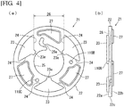
- the first bracket 21 includes a circular body 22, three guides 23 that respectively guide movement of the first pawl 40A, the second pawl 40B, and the third pawl 40C, and projections 27 that attach the first bracket 21 to the plate 3a, which serves as a fixing member.
- Each guide 23 projects from an inner surface 22a of the body 22.
- Each guide 23 includes guide surfaces 24 extending toward the outside and an inner side surface 23a extending in the circumferential direction.
- the cam 50 is accommodated in a region surrounded by the inner side surfaces 23a of the three guides 23.
- the three opposing guide surfaces 24 of two adjacent guides 23 are parallel to each other.
- the guide surfaces 24 form guide grooves 26 in cooperation with the inner surface 22a of the body 22.
- the guide grooves 26 guide the first pawl 40A, the second pawl 40B, and the third pawl 40C to move in the radial direction.
- the three guides 23 have the same shape and are arranged in the circumferential direction at equal angles.
- the three guide grooves 26 are arranged in the circumferential direction at equal angular intervals.
- the first bracket 21 includes an outer surface 22b recessed at portions located at the opposite side of the guides 23.
- the projections 27 project from portions of the outer surface 22b of the body 22 located at the opposite side of the guide grooves 26.
- the inner surface 22a of the first bracket 21 is recessed at the opposite side of the projections 27.
- the projections 27 of the first bracket 21 are fitted into holes or cutouts arranged in the plate 3a and welded to the plate 3a.
- the central portion of the body 22 includes an accommodation portion 25 that accommodates a spiral portion 61 of the spiral spring 60.
- the accommodation portion 25 is provided with a communication groove 25a cut out toward the radially outer side.
- An outer engagement portion 62 and an end 62a of the spiral spring 60 shown in Fig. 3 are engaged with the communication groove 25a.
- an engagement projection 110B and an engagement projection 110C project from the inner surface 22a.
- the engagement projection 110B is slidably inserted into a sliding groove 112B of the second pawl 40B, which will be described later.
- the engagement projection 110C is slidably inserted into a sliding groove 112C of the third pawl 40C, which will be described later.
- the cam 50 is located between the first bracket 21 and the second bracket 31.
- the cam 50 is accommodated in the region surrounded by the inner side surfaces 23a of the three guides 23 of the first bracket 21.
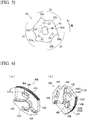
- the cam 50 includes a cam body 51, three pawl engagement portions 52, and two spring engagement portions 53 that engage with an inner engagement portion 63 of the spiral spring 60 shown in Figs. 3 and 5 .
- the three pawl engagement portions 52 engage the first pawl 40A, the second pawl 40B, and the third pawl 40C, respectively.
- the pawl engagement portions 52 are arranged on a first surface 50a of the cam 50, and the spring engagement portions 53 are arranged on a second surface 50b, which is shown in Fig. 2 , of the cam 50.
- a fitting hole 54 into which the shaft 5 is fitted extends through a central portion of the cam body 51.
- the cam 50 moves in cooperation with the rotation of the shaft 5. More specifically, operation of the operation lever 5a attached to the shaft 5 rotates the cam 50.
- the circumferential surface of the cam body 51 is provided with three cam portions, namely, a first cam portion 55, a second cam portion 56, and a third cam portion 57, which respectively come into contact with cam surfaces of the first pawl 40A, the second pawl 40B, and the third pawl 40C and which are arranged at equal angular intervals.
- the first cam portion 55 includes a first pushing portion 55a and a second pushing portion 55b that push a first cam surface 44A of the first pawl 40A.
- the second cam portion 56 includes a first pushing portion 56a and a second pushing portion 56b that push a second cam surface 44B of the second pawl 40B.
- the third cam portion 57 includes a first pushing portion 57a and a second pushing portion 57b that push a third cam surface 44C of the third pawl 40C (see Fig. 10 ).
- the cam 50 is biased by the spiral spring 60 in a predetermined rotation direction relative to the first bracket 21 (hereinafter referred to as "biasing direction RB"). That is, the spiral spring 60 applies a biasing force that rotates the cam 50 in the biasing direction RB to the cam 50.
- the first pawl 40A includes a first block 41A and a second block 42A which are arranged in different steps. More specifically, the first block 41A is located at the radially outer side of the first pawl 40A, and the second block 42A is located at the radially inner side of the first pawl 40A. The first block 41A is shifted from the second block 42A in the axial direction of the rotation axis C2.
- the first block 41A is attached to the guide grooves 26 of the first bracket 21.
- the first block 41A and the cam 50 are located at the same position in the axial direction of the rotation axis C2.
- the first block 41A has an arcuate outer end surface opposing inner teeth 37 of the second bracket 31.
- the outer end surface of the first block 41A has outer teeth 43A that mesh with the inner teeth 37 of the second bracket 31.
- the end surface of the first block 41A located at a side opposite to the outer end surface has the first cam surface 44A against which the first cam portion 55 of the cam 50 abuts.
- the first cam surface 44A has a portion against which the first pushing portion 55a of the first cam portion 55 abuts and a portion against which the second pushing portion 55b of the first cam portion 55 abuts.
- the second block 42A is arranged on the first surface 50a of the cam 50. That is, the second block 42A is located between the cam 50 and the second bracket 31.
- the second block 42A has an outer end surface opposing the inner surface of a step 34 of the second bracket 31.
- a first limitation portion 46A is provided between the outer end surface of the second block 42A and the outer end surface (the outer teeth 43A) of the first block 41A.
- the first limitation portion 46A projects from the surface of the first block 41A toward the second bracket 31.
- the first limitation portion 46A abuts against the first pawl restriction portion 34a of the second bracket 31 shown in Fig. 7(a) to limit the first pawl 40A to move toward the radially outer side.
- the first limitation portion 46A has an abutment surface 48A that abuts against a first inner surface 35a of the first pawl restriction portion 34a.
- the distance in the radial direction between the abutment surface 48A of the first limitation portion 46A and the outer teeth 43A is restricted by a predetermined distance in relation to the step structure of the second bracket 31.
- a cam hole 47A that penetrates through the second block 42A in the thickness direction is provided at the central portion of the second block 42A.
- the cam hole 47A extends in the circumferential direction toward the inner side in the biasing direction RB shown in Fig. 3 .
- the corresponding pawl engagement portion 52 of the cam 50 is inserted through the cam hole 47A (see Fig. 6 ).
- the second pawl 40B has the same structure as the first pawl 40A except for the positional structure of the second limitation portion 46B, namely, the positional relationship of an abutment surface 48B of the second limitation portion 46B and outer teeth 43B, and except for the structure of a first clearance portion 100B of the second limitation portion 46B and a sliding groove 112B.
- a negative side end 102B of the second limitation portion 46B is provided with the first clearance portion 100B having a corner portion removed and having an inclined surface 104B, of which a height is changed in the radial direction.
- the inclined surface 104B is a smooth surface whose radial height gradually increases from the negative side end 102B toward the abutment surface 48B.
- the inclined surface 104B may be straight or curved when viewed in a cross-sectional view.
- the first clearance portion 100B may have a shape having a surface whose radial height does not increase halfway without being limited to the inclined surface 104B.
- the first clearance portion 100B may be provided at a positive side end 106B of a second pawl restriction portion 34b without being limited to the negative side end 102B of the second limitation portion 46B.
- the surface shape at this time may be a smooth surface whose radial height gradually decreases, or may be a shape partially having a surface whose radial height does not increase.
- the second pawl 40B is provided with the sliding groove 112B corresponding to the engagement projection 110B.
- the sliding groove 112B in the present embodiment is provided as a hole penetrating in the thickness direction of the second pawl 40B from the viewpoint of improving visibility when assembling to the first bracket 21.
- the sliding groove 112B extends in a direction along the guide groove 26 of the first bracket 21. That is, the sliding groove 112B extends along the movement of the second pawl 40B in the radial direction.
- the outer teeth 43B side of the sliding grooves 112B has a groove shape which is larger than a diameter of the engagement projection 110B.
- the sliding groove 112B has a groove shape that is tapered toward the radially inner side inward from the outer teeth 43B. A tip end of the groove shape is smaller than the diameter of the engagement projection 110B.
- the sliding groove 112B is biased in a direction intersecting the radial movement of the second pawl 40B in a state where the outer teeth 43B
- the tapered shape of the sliding groove 112B has a first gradually changing portion 114B and a second gradually changing portion 116B toward the radially inner side from the outer teeth 43B side.
- Each of the first gradually changing portion 114B and the second gradually changing portion 116B is provided as an inclined surface intersecting the radial movement of the second pawl 40B.
- the inclination angle of the second gradually changing portion 116B is set larger than that of the first gradually changing portion 114B.
- the radius of curvature of the outer teeth 43B of the second pawl 40B is smaller than the radius of curvature of the inner teeth 37 of the second bracket 31. Therefore, in a state where the outer teeth 43B mesh with the inner teeth 37, the vicinity of the center in the circumferential direction of the outer teeth 43B mesh deeply, and both ends in the circumferential direction mesh shallowly. This is because a tolerance is required to smoothly mesh the outer teeth 43B with the inner teeth 37. On the other hand, due to such tolerance, rattling may occur when the outer teeth 43B mesh with the inner teeth 37. Therefore, the sliding groove 112B and the engagement projection 110B contribute to prevention of rattling of the second pawl 40B.
- the present embodiment shows an aspect in which the engagement projection 110B is provided on the first bracket 21 and the sliding groove 112B is provided on the second pawl 40B.
- the sliding groove 112B can be easily formed on the second pawl 40B, which is an internal component.
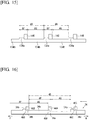
- the relationship between the engagement projection 110B and the sliding groove 112B may be reversed. That is, as shown in Fig. 17 , the engagement projection 110B may be provided on the second pawl 40B, and the sliding groove 112B may be provided on the first bracket 21.
- the sliding groove 112B may have a groove shape that does not penetrate in the thickness direction of the second pawl 40B.
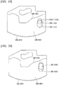
- the sliding groove 112B may be formed into a groove shape tapered in a straight shape as shown in Fig. 18 , instead of the tapered groove shape as shown in Fig. 10 whose middle portion in the radial direction is bent.
- a surface of the sliding groove 112B that abuts against the engaged protrusion 110B in a rattling tightening state may be formed of arcuate surfaces 112Ba that are warped in a reverse direction so as to be in point contact (linear contact) with the circular outer peripheral surface of the engagement projection 110B.
- the engagement projection 110B may protrude into a pin shape having a wide cross-sectional width in the radial direction such as an ellipse instead of a pin shape protruding into a circular shape.
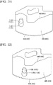
- the rattling tightening structure formed by the sliding groove 112B and the engagement projection 110B may be set not in the end region on the one side in the circumferential direction of the second pawl 40B as shown in Fig. 10 , but in an end region on the other side in the circumferential direction as shown in Fig. 21 or the intermediate region in the circumferential direction as shown in Fig. 22 .
- the third pawl 40C has the same structure as the first pawl 40A except for the positional structure of the third limitation portion 46C, namely, the positional relationship of an abutment surface 48C of the third limitation portion 46C and outer teeth 43C, and except for the structure of a second clearance portion 100C and a sliding groove 112C on the third limitation portion 46C.
- a negative side end 102C of the third limitation portion 46C is provided with the second clearance portion 100C having a corner portion removed and having an inclined surface 104C, of which a height is changed in the radial direction.
- the inclined surface 104C is a smooth surface whose radial height gradually increases from the negative side end 102C toward the abutment surface 48C.
- the inclined surface 104C may be straight or curved when viewed in a cross-sectional view.
- the second clearance portion 100C may have a shape having a surface whose radial height does not increase halfway without being limited to the third limitation portion 46C.
- the second clearance portion 100C may be provided at a positive side end 106C of a third pawl restriction portion 34c without being limited to the negative side end 102C of the third limitation portion 46C.
- the surface shape at this time may be a smooth surface whose radial height gradually decreases, or may be a shape partially having a surface whose radial height does not increase.
- the third pawl 40C is provided with the sliding groove 112C corresponding to the engagement projection 110C.
- the sliding groove 112C in the present embodiment is provided as a hole penetrating in the thickness direction of the third pawl 40C from the viewpoint of improving visibility when assembling to the first bracket 21.
- the sliding groove 112C extends in a direction along the guide groove 26 of the first bracket 21. That is, the sliding groove 112C extends along the movement of the third pawl 40C in the radial direction.
- the outer teeth 43C side of the sliding grooves 112C has a groove shape which is larger than a diameter of the engagement projection 110C.
- the sliding groove 112C has a groove shape that is tapered toward the radially inner side from the outer teeth 43C. A tip end of the groove shape is smaller than the diameter of the engagement projection 110C.
- the sliding groove 112C is biased in a direction intersecting the radial movement of the third pawl 40C in a state where the outer teeth 43C mesh with
- the tapered shape of the sliding groove 112C has a first gradually changing portion 114C and a second gradually changing portion 116C toward the radially inner side from the outer teeth 43C side.
- Each of the first gradually changing portion 114C and the second gradually changing portion 116C is provided as an inclined surface intersecting the radial movement of the third pawl 40C.
- the inclination angle of the second gradually changing portion 116C is set larger than that of the first gradually changing portion 114C.
- the radius of curvature of the outer teeth 43C of the third pawl 40C is smaller than the radius of curvature of the inner teeth 37 of the second bracket 31. Therefore, in a state where the outer teeth 43C mesh with the inner teeth 37, the vicinity of the center in the circumferential direction of the outer teeth 43C mesh deeply, and both ends in the circumferential direction mesh shallowly. This is because a tolerance is required to smoothly mesh the outer teeth 43C with the inner teeth 37. On the other hand, due to such tolerance, rattling may occur when the outer teeth 43B mesh with the inner teeth 37. Therefore, the sliding groove 112C and the engagement projection 110C contribute to prevention of rattling of the third pawl 40C.
- the present embodiment shows an aspect in which the engagement projection 110C is provided on the first bracket 21 and the sliding groove 112C is provided on the third pawl 40C.
- the sliding groove 112C can be easily formed on the third pawl 40C, which is an internal component.
- the relationship between the engagement projection 110C and the sliding groove 112C may be reversed. That is, as shown in Fig. 17 , the engagement projection 110C may be provided on the third pawl 40C, and the sliding groove 112C may be provided on the first bracket 21.
- the sliding groove 112C may have a groove shape that does not penetrate in the thickness direction of the third pawl 40C.
- the sliding groove 112C may be formed into a groove shape tapered in a straight shape as shown in Fig. 18 , instead of the tapered groove shape as shown in Fig. 10 whose middle portion in the radial direction is bent.
- a surface of the sliding groove 112C that abuts against the engaged protrusion 110C in a rattling tightening state may be formed of arcuate surfaces 112Ca that are warped in a reverse direction so as to be in point contact (linear contact) with the circular outer peripheral surface of the engagement projection 110C.
- the engagement projection 110C may protrude into a pin shape having a wide cross-sectional width in the radial direction such as an ellipse instead of a pin shape protruding into a circular shape.
- the rattling tightening structure formed by the sliding groove 112C and the engagement projection 110C may be set not in the end region on the one side in the circumferential direction of the third pawl 40C as shown in Fig. 10 , but in an end region on the other side in the circumferential direction as shown in Fig. 21 or the intermediate region in the circumferential direction as shown in Fig. 22 .
- the present embodiment shows an aspect in which both the engagement projection 110B, the sliding groove 112B and the engagement projection 110C, the sliding groove 112C are formed, but may also be an aspect having one combination of the engagement projection 110B, the sliding groove 112B or the engagement projection 110C, the sliding groove 112C.
- the rattling tightening structure formed by the engagement projection and the sliding groove may be configured such that an engagement projection 110A and a sliding groove 112A are provided between the first pawl 40A and the first bracket 21.
- the engagement projections 110B, 110C and the sliding grooves 112B, 112C may be fitted to one another loosely so that a slight gap is formed in the circumferential direction when the engagement projection 110A is fitted into the sliding groove 112A and enters the rattling tightening state, which provides an auxiliary rattling tightening function.
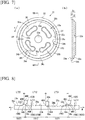
- the second bracket 31 will now be described with reference to Fig. 7(a) to 9 .
- the second bracket 31 includes a circular body 32 and an outer circumferential wall 33 arranged along an outer edge of the body 32.
- An insertion hole 32a through which the shaft 5 is inserted is formed in the body 32.
- the inner teeth 37 are arranged over the entire circumference of an inner circumferential surface 33a of the outer circumferential wall 33.
- the inner teeth 37 mesh with the outer teeth 43A of the first pawl 40A, the outer teeth 43B of the second pawl 40B, and the outer teeth 43C of the third pawl 40C.
- the outer circumferential surface 33b of the outer circumferential wall 33 comes into sliding contact with the holding member 80.
- the outer surface 33c of the outer circumferential wall 33 comes into sliding contact with the projection 83 of the holding member 80 shown in Fig. 2 .
- the inner surface of the body 32 includes an annular step 34 about the rotation axis C2.
- Fig. 8 corresponds to a schematic view in which the cross section along line XII-XII in Fig. 2 is spread out, and the step 34 and the first limitation portion 46A to third limitation portion 46C of the first pawl 40A to the third pawl 40C are cut out.
- the step 34 includes, sequentially in the positive direction F, a first pawl allowance portion 34x, the first pawl restriction portion 34a, the second pawl restriction portion 34b, a second pawl allowance portion 34y, and the third pawl restriction portion 34c.
- the first pawl allowance portion 34x allows the first pawl 40A to move toward the radially outer side.
- the first pawl allowance portion 34x includes an inner surface 35x having a predetermined radius, that is, a radius extending about the rotation axis C2.
- the inner surface 35x of the first pawl allowance portion 34x is configured such that, when the first pawl 40A moves toward the radially outer side with the first limitation portion 46A being located at the first pawl allowance portion 34x, the first limitation portion 46A does not comes into contact with the inner surface 35x until the outer teeth 43A of the first pawl 40A mesh with the inner teeth 37. That is, the distance LRa between the inner teeth 37 of the second bracket 31 and the inner surface 35x of the first pawl allowance portion 34x shown in Fig. 7(a) is slightly less than or equal to the distance LP1 between the outer teeth 43A of the first pawl 40A and the abutment surface 48A of the first limitation portion 46A shown in Fig. 6 (a) .
- the first pawl restriction portion 34a restricts the first pawl 40A to move toward the radially outer side.
- the first pawl restriction portion 34a includes the first inner surface 35a having a smaller radius than the inner surface 35x of the first pawl allowance portion 34x.
- the first pawl restriction portion 34a extends in the positive direction F from the first pawl allowance portion 34x and is longer in the circumferential direction than the second pawl restriction portion 34b. More specifically, the first pawl restriction portion 34a extends to a negative side end 36b of the second pawl restriction portion 34b.
- the first inner surface 35a of the first pawl restriction portion 34a is configured such that, when the first pawl 40A moves toward the radially outer side with the first limitation portion 46A being located on the first pawl restriction portion 34a, the outer teeth 43A of the first pawl 40A are separated from the inner teeth 37 of the second bracket 31 in a state where the first limitation portion 46A abuts against the first inner surface 35a.
- the first inner surface 35a of the first pawl restriction portion 34a is configured such that, when the second pawl 40B moves toward the radially outer side with the second limitation portion 46B being located on the first pawl restriction portion 34a, the second limitation portion 46B does not come into contact with the first inner surface 35a of the first pawl restriction portion 34a until the outer teeth 43B of the second pawl 40B mesh with the inner teeth 37.
- the distance LR1 between the inner teeth 37 of the second bracket 31 and the first inner surface 35a of the first pawl restriction portion 34a is longer than the distance LP1 between the outer teeth 43A of the first pawl 40A and the abutment surface 48A of the first limitation portion 46A, and slightly less than or equal to the distance LP2 between the outer teeth 43B of the second pawl 40B and the abutment surface 48B of the second limitation portion 46B shown in Figs. 3 and 6(a) .
- the second pawl restriction portion 34b restricts the second pawl 40B to move toward the radially outer side.
- the second pawl restriction portion 34b has a second inner surface 35b having a smaller radius than the first inner surface 35a of the first pawl restriction portion 34a.
- the second inner surface 35b of the second pawl restriction portion 34b is configured such that, when the second pawl 40B moves toward the radially outer side with the second limitation portion 46B being located at the second pawl restriction portion 34b, the outer teeth 43B of the second pawl 40B are separated from the inner teeth 37 of the second bracket 31 in a state where the second limitation portion 46B abuts against the second inner surface 35b. That is, the distance LR2 between the inner teeth 37 of the second bracket 31 and the second inner surface 35b of the second pawl restriction portion 34b shown in Fig. 7(a) is longer than the distance LP2 between the outer teeth 43B of the second pawl 40B and the second limitation portion 46B.
- the second pawl allowance portion 34y allows the third pawl 40C to move toward the radially outer side.
- the second pawl allowance portion 34y has an inner surface 35y having a larger radius than the second inner surface 35b of the second pawl restriction portion 34b.
- the inner surface 35y of the second pawl allowance portion 34y is configured such that, when the third pawl 40C moves toward the radially outer side with the third limitation portion 46C being located at the second pawl allowance portion 34y, the third limitation portion 46C does not come into contact with the inner surface 35y of the second pawl allowance portion 34y until the outer teeth 43C of the third pawl 40C mesh with the inner teeth 37. That is, the distance LRb between the inner teeth 37 of the second bracket 31 and the inner surface 35y of the second pawl allowance portion 34y shown in Fig. 7(a) is slightly less than or equal to the distance LP3 between the outer teeth 43C of the third pawl 40C and the abutment surface 48C of the third limitation portion 46C shown in Fig. 3 .
- the third pawl restriction portion 34c restricts the third pawl 40C to move toward the radially outer side.
- the third pawl restriction portion 34c includes a third inner surface 35c having a smaller radius than the first inner surface 35a of the first pawl restriction portion 34a.
- the third inner surface 35c of the third pawl restriction portion 34c is configured such that, when the third pawl 40C moves toward the radially outer side with the third limitation portion 46C being located at the third pawl restriction portion 34c, the outer teeth 43C of the third pawl 40C are separated from the inner teeth 37 of the second bracket 31 in a state where the third limitation portion 46C abuts against the third inner surface 35c. That is, the distance LR3 between the inner teeth 37 of the second bracket 31 and the third inner surface 35c of the third pawl restriction portion 34c shown in Fig. 7(a) is longer than the distance LP3 between the third pawl 40C and the third limitation portion 46C.
- the distance LT12 between a side surface of the first limitation portion 46A of the first pawl 40A facing the positive direction F and a side surface of the second limitation portion 46B of the second pawl 40B facing the positive direction F is equal to the distance LU12 from an end surface of the first pawl restriction portion 34a facing the negative direction N.
- the distance LT23 between a side surface of the second limitation portion 46B of the second pawl 40B facing the positive direction F and a side surface of the third limitation portion 46C of the third pawl 40C facing the positive direction F is equal to the distance LU23 between an end surface of the second pawl restriction portion 34b facing the negative direction N and an end surface of the third pawl restriction portion 34c facing the negative direction N.
- the distance LT31 between a side surface of the third limitation portion 46C of the third pawl 40C facing the positive direction F and a side surface of the first limitation portion 46A of the first pawl 40A facing the positive direction F is equal to the distance LU31 between an end surface of the third pawl restriction portion 34c facing the negative direction N and an end surface of the first pawl restriction portion 34a facing the negative direction N.
- the distance relationship of the first to third limitation portions 46A to 46C and the first to third pawl restriction portions 34a to 34c in the circumferential direction are hereinafter referred to as the "circumferential structure of pawl movement limitation".
- Fig. 9 only shows the first to third limitation portions 46A to 46C, and shows the positional relationship of the first to third limitation portions 46A to 46C which is set by engagement with the cam 50 without force being applied to any of the first to third limitation portions 46A to 46C.
- the abutment surface 48A of the first limitation portion 46A is located at the radially outer side from the abutment surface 48B of the second limitation portion 46B.
- the separation distance LH12 between the abutment surface 48A of the first limitation portion 46A and the second limitation portion 46B is larger than the step distance LZ12 between the first inner surface 35a of the first pawl restriction portion 34a and the second inner surface 35b of the second pawl restriction portion 34b.
- the difference between the separation distance LH12 and the step distance LZ12 is set to a slight distance that can be cancelled by pushing force of external factors (described below).
- the abutment surface 48A of the first limitation portion 46A is located at the radially outer side from the abutment surface 48C of the third limitation portion 46C.
- the separation distance LH13 between the abutment surface 48A of the first limitation portion 46A and the abutment surface 48C of the third limitation portion 46C is larger than the step distance LZ13 between the first inner surface 35a of the first pawl restriction portion 34a and the third inner surface 35c of the third pawl restriction portion 34c.
- the difference between the separation distance LH13 and the step distance LZ13 is set to a slight distance that can be cancelled by pushing force of external factors (described below).
- the distance relationship of the first to third limitation portions 46A to 46C and the first to third pawl restriction portions 34a to 34c in the radial direction is hereinafter referred to as the "radial structure of pawl movement limitation”.
- the rotation angle of the second bracket 31 relative to the first bracket 21 is a predetermined value (hereinafter referred to as specified angle)
- positive side corners 49A to 49C of the first to third limitation portions 46A to 46C may abut against negative side ends 36a to 36c of the first to third pawl restriction portions 34a to 34c, respectively.
- Fig. 10 shows a locked state in which the outer teeth 43A to 43C of the pawls 40A to 40C are meshed with the inner teeth 37 of the second bracket 31.
- Fig. 11 shows an unlocked state in which the outer teeth 43A to 43C of the pawls 40A to 40C are not meshed with the inner teeth 37 of the second bracket 31 when each of the pawls 40A to 40C is kept at the radially inner side.
- Fig. 12 shows a lock limitation state in which the outer teeth 43A to 43C of the pawls 40A to 40C do not mesh with the inner teeth 37 of the second bracket 31 when the first pawl 40A is limited to move toward the radially outer side.
- the vehicle seat reclining device 10 performs the two basic operations described below.
- the first basic operation is a movement of each of the pawls 40A to 40C when the operation lever 5a is operated to rotate the cam 50.
- the second basic operation limits the movement of each of the pawls 40A to 40C controlled by the rotation angle of the second bracket 31.
- the first to third pawls 40A to 40C operate in the same manner.
- the first pawl 40A will now be described as an example.
- the cam 50 is biased to rotate in the biasing direction RB.
- the first cam portion 55 pushes the first cam surface 44A of the first pawl 40A, thus, the first pawl 40A moves toward the radially outer side.
- the outer teeth 43A of the first pawl 40A mesh with the inner teeth 37 of the second bracket 31. Accordingly, the second bracket 31 is fixed to the first bracket 21 and the vehicle seat reclining device 10 is shifted to the locked state.
- the operation lever 5a When the operation lever 5a is operated to rotate the cam 50 in the direction opposite to the biasing direction RB, the pawl engagement portion 52 of the cam 50 pushes the inner surface of the cam hole 47A of the first pawl 40A, and thus, the first pawl 40A moves toward the radially inner side. After that, the outer teeth 43A of the first pawl 40A are separated from the inner teeth 37 of the second bracket 31 as shown in Fig. 11 . As a result, the second bracket 31 becomes non-rotatable relative to the first bracket 21 and the vehicle seat reclining device 10 is shifted to the unlocked state.
- the outer teeth 43A of the first pawl 40A remain separated from the inner teeth 37 of the second bracket 31. Further, abutment of the first limitation portion 46A of the first pawl 40A against the first pawl restriction portion 34a of the second bracket 31 stops rotation of the cam 50 and restricts the second pawl 40B and the third pawl 40C to move toward the outer side. As a result, the outer teeth 43B of the second pawl 40B and the outer teeth 43C of the third pawl 40C are separated from the inner teeth 37 of the second bracket 31.
- the vehicle seat reclining device 10 becomes into the lock limitation state in which the vehicle seat reclining device 10 is limited to become the locked state, that is, a state in which the second bracket 31 is allowed to rotate.
- Figs. 13(a) and 14(a) show the positional relationship of the first pawl 40A to the third pawl 40C and the first pawl restriction portion 34a to the third pawl restriction portion 34c when the second bracket 31 is slightly rotated from a specified angle relative to the first bracket 21 in the positive direction F.
- the first limitation portion 46A of the first pawl 40A is located at the first pawl allowance portion 34x
- the second limitation portion 46B of the second pawl 40B is located at the first pawl restriction portion 34a
- the third limitation portion 46C of the third pawl 40C is located at the second pawl allowance portion 34y.
- the first pawl allowance portion 34x allows the first pawl 40A to move toward the radially outer side
- the first pawl restriction portion 34a allows the second pawl 40B to move toward the radially outer side
- the second pawl allowance portion 34y allows the third pawl 40C to move toward the radially outer side.
- the vehicle seat reclining device 10 may shift to the locked state.
- Figs. 13(b) and 14(b) show the positional relationship of the first limitation portion 46A to the third limitation portion 46C of the first pawl 40A to the third pawl 40C when the second bracket 31 is rotated by a predetermined angle from the specified angle relative to the first bracket 21 in the positive direction F.
- the third limitation portion 46C of the third pawl 40C approaches an end of the second pawl restriction portion 34b facing the positive direction F.
- the first limitation portion 46A to the third limitation portion 46C of the first pawl 40A to the third pawl 40C and the step 34 of the second bracket 31 is substantially equal to the relationship shown in Fig. 14(a) .
- the vehicle seat reclining device 10 may shift to the locked state.
- An angle range in which the first limitation portion 46A of the first pawl 40A is disposed at the position of the first pawl allowance portion 34x is defined as a "second bracket rotation limitation range" (in other words, referred to as a locked zone).
- Figs. 13(c) and 14(c) show the positional relationship of the first limitation portion 46A to the third limitation portion 46C of the first pawl 40A to the third pawl 40C when the second bracket 31 is rotated slightly from the specified angle relative to the first bracket 21 in the negative direction N.
- the first limitation portion 46A of the first pawl 40A is located at the first pawl restriction portion 34a and is in contact with the first pawl restriction portion 34a.
- the vehicle seat reclining device 10 may shift to the lock limitation state.
- the second limitation portion 46B of the second pawl 40B is located at the second pawl restriction portion 34b
- the third limitation portion 46C of the third pawl 40C is located at the third pawl restriction portion 34c.
- the first pawl restriction portion 34a restricts the first pawl 40A to move toward the radially outer side.
- the second limitation portion 46B of the second pawl 40B is not in contact with the second pawl restriction portion 34b.
- an external factor (described below) applies a pushing force
- the second limitation portion 46B of the second pawl 40B may be restricted to move toward the radially outer side by the second pawl restriction portion 34b.
- the third limitation portion 46C of the third pawl 40C is not in contact with the third pawl restriction portion 34c.
- the third limitation portion 46C of the third pawl 40C may be restricted to move toward the radially outer side by the third pawl restriction portion 34c.
- Fig. 14(c) shows that the second limitation portion 46B is in contact with the second pawl restriction portion 34b and the third limitation portion 46C is in contact with the third pawl restriction portion 34c. Nevertheless, as described above, each limitation portion is normally not in contact with the corresponding pawl restriction portion when the external factor does not apply the pushing force.
- Figs. 13(d) and 14(d) show the positional relationship of the first limitation portion 46A to the third limitation portion 46C of the first pawl 40A to the third pawl 40C when the second bracket 31 is rotated by the predetermined angle from the specified angle relative to the first bracket 21 in the negative direction N.
- the first limitation portion 46A of the first pawl 40A is located at the first pawl restriction portion 34a, and the side surface of the first limitation portion 46A of the first pawl 40A facing the positive direction approaches the second pawl restriction portion 34b. Accordingly, the first pawl 40A is restricted to move toward the radially outer side, and the second bracket 31 is restricted to move in the negative direction N.
- the range of Figs. 13(c) and 13(d) is the “second bracket rotation allowance range” in which rotation of the second bracket 31 with respect to the first bracket 21 is allowed.
- the range of Figs. 13(a) and 13(b) is the “second bracket rotation limitation range” in which rotation of the second bracket 31 with respect to the first bracket 21 is limited.
- the second limitation portion 46B and the third limitation portion 46C when the first limitation portion 46A transitions from the angle at which the first limitation portion 46A engages with the first pawl restriction portion 34a ( Figs. 13(c) and 13(d) : the "second bracket rotation allowance range") to the angle at which the first limitation portion 46A engages with the first pawl allowance portion 34x ( Figs. 13 (a) and 13 (b) : the "second bracket rotation limitation range”) among the rotation angles of the second bracket 31 with respect to the first bracket 21 will be described.
- the negative side end 102C of the third limitation portion 46C and the positive side end 106C of the third pawl restriction portion 34c come into contact with each other in a direction inclined with respect to the rotation direction of the second bracket 31 with respect to the first bracket 21 due to the first clearance portion 100C, and thus catching is prevented. That is, the inclined surface 104B of the first clearance portion 100B has a surface shape that prevents catching when returning from the free zone to the locked zone. Similarly, the inclined surface 104C of the second clearance portion 100C has a surface shape that prevents catching when returning from the free zone to the locked zone.
- the step structure of the second bracket 31 will now be described with reference to Fig. 14(c) .
- the first limitation portion 46A of the first pawl 40A is in contact with the first pawl restriction portion 34a.
- the second limitation portion 46B of the second pawl 40B may be separated from or come into sliding contact with the second pawl restriction portion 34b.
- the third limitation portion 46C of the third pawl 40C may be separated from or come into sliding contact with the third pawl restriction portion 34c.
- the first limitation portion 46A of the first pawl 40A comes into sliding contact with the first pawl restriction portion 34a.
- Continuous rotation of the second bracket 31 gradually decreases the contact area of the first limitation portion 46A of the first pawl 40A and the first pawl restriction portion 34a, the contactable area of the second limitation portion 46B of the second pawl 40B and the second pawl restriction portion 34b, and the contactable area of the third limitation portion 46C of the third pawl 40C and the third pawl restriction portion 34c in the same manner.
- the positive side corner 49A of the first limitation portion 46A may abut against the negative side end 36a of the first pawl restriction portion 34a
- the positive side corner 49B of the second limitation portion 46B may abut against the negative side end 36b of the second pawl restriction portion 34b
- the positive side corner 49C of the third limitation portion 46C may abut against the negative side end 36c of the third pawl restriction portion 34c.
- the contactable area of the second pawl 40B and the second pawl restriction portion 34b represents a contactable area when the second pawl 40B moves toward the radially outer side so that the second limitation portion 46B of the second pawl 40B comes into contact with the second pawl restriction portion 34b.
- the pushing force of the cam 50 caused by external factors that cause the cam 50 to rotate concentrates in a positive side corner of the limitation portion when the second bracket 31 reaches the specified angle to reduce the contact area.
- the cam 50 is biased by the spiral spring 60 in the biasing direction RB.
- the pushing force of the cam 50 based on the force of the spiral spring 60 concentrates in the positive side corner of the limitation portion.
- the above-described structure disperses the pushing force of the cam 50 to the first limitation portion 46A to the third limitation portion 46C. Accordingly, deformation of the first pawl 40A to the third pawl 40C, in particular, the first pawl 40A to the third pawl 40C (in particular, the first limitation portion 46A to the third limitation portion 46C) is prevented.
- the cam 50 is rotated by an external factor in the following case.
- the vehicle seat reclining devices 10 are arranged at the left and right sides of the seat 2.
- the cams 50 of the left and right seat reclining devices 10 move in cooperation.
- the vehicle seat reclining devices 10 normally shift from the lock limitation state to the locked state at the same timing.
- only one of the vehicle seat reclining devices 10 shifts to the locked state, and the other vehicle seat reclining device 10 is maintained in the lock limitation state.
- one of the vehicle seat reclining devices 10 fixes the seat back 4 to the seat cushion 3 to restrict rotation of the second bracket 31, and the other vehicle seat reclining device 10 is maintained in the lock limitation state.
- the first bracket 21 and the second bracket 31 may rotate relatively, and the cams 50 rotate easily.
- swinging of the seat 2 in the front-to-rear direction, vibration of the vehicle, and the like slightly swing the operation lever 5a.
- the vehicle occupant pushes the operation lever 5a to limit swinging of the operation lever 5a and performs procedures in an order reversed from unlocking.
- This rotates the cam 50 in the biasing direction RB, which corresponds to the case in which the cam 50 is rotated by external factors.
- the pushing force that rotates the operation lever 5a is applied to the pawls through the cam 50.
- a biasing force of the spiral spring 60 that is, a larger force than the force normally applied to the cam 50, is applied to the pawls as the pushing force of external factors.
- Fig. 15 shows the step structure of the second bracket 31 in the related art.
- pawl restriction portions 134a and pawl allowance portions 134b are arranged in correspondence with first to third limitation portions 146.
- the pawl restriction portions 134a and the pawl allowance portions 134b are arranged alternately in the circumferential direction.
- the rim of the second bracket 31 is divided into three regions, and the pawl restriction portion 134a and the pawl allowance portion 134b are arranged at each region.
- the same effect as the present embodiment described above is obtained.
- the following problem occurs.
- the range in which the first pawl 40A to the third pawl 40C are allowed to move toward the radially outer side at the step 34 of the second bracket 31 is defined as the "pawl movement allowance range AQ”.
- the range in which the first pawl 40A to the third pawl 40C are restricted to move toward the radially outer side at the step 34 of the second bracket 31 is defined as the "pawl movement restriction range AP”.
- the range that is the sum of the pawl movement allowance range AQ and the pawl movement restriction range AP is defined as the "control range AR".
- the control ranges AR of the first pawl 40A to the third pawl 40C do not overlap.
- the rotation angle of the second bracket 31 corresponding to the control range AR (hereinafter referred to as control angle range) is virtually less than or equal to 120 degrees, and the control angle range cannot be greater than or equal to 120 degrees.
- the control angle range that is greater than 120 degrees is effective for forming the vehicle seat reclining device 10 in the manner described below.
- the vehicle seat reclining device 10 can be in the lock limitation state in the range from the reference position to 50 degrees in front of the seat back 4 and in the locked state in the range from the reference position to 80 degrees behind the seat back 4.
- the control angle range is 130 degrees, and the control angle range can be greater than or equal to 120 degrees.
- the vehicle seat reclining device having the structure of the related art shown in Fig. 15 cannot be used for a vehicle that requires such a specification.
- Fig. 16 shows the step structure of the second bracket 31 of the first embodiment.
- the first pawl restriction portion 34a and the second pawl restriction portion 34b are located at different positions in the radial direction. Further, the first pawl restriction portion 34a of the second bracket 31 extends to the negative side end 36b of the second pawl restriction portion 34b, which differs from the structure of the related art.
- the pawl movement restriction range AP of the first pawl 40A overlaps the pawl movement allowance range AQ of the second pawl 40B (this structure is hereinafter referred to as overlapping structure of control range AR).
- This structure expands the control range AR and the control angle range of the second bracket 31 as compared with the structure of the related art in which the pawl movement restriction range AP of the first pawl 40A does not overlap the pawl movement allowance range AQ of the second pawl 40B.
- the first limitation portion 46A to the third limitation portion 46C are respectively in contact with the first pawl allowance portion 34x, the first pawl restriction portion 34a, and the second pawl restriction portion 34b, or may be in a contactable state, namely, a state of coming into contact when force is applied from the cam 50.
- the positions of the second pawl 40B and the third pawl 40C in the radial direction are controlled by the cam 50 by the first pawl 40A being in contact with the step 34.
- the number of the first limitation portion 46A to the third limitation portion 46C that are in contact with the step 34 changes in accordance with whether the vehicle seat reclining device 10 is in the locked state or the lock limitation state (hereinafter referred to as limitation portion engagement structure). This structure expands the control angle and obtains strength for the locked state.
- the negative side end 102B of the second limitation portion 46B is provided with the first clearance portion 100B having a corner portion removed and having the inclined surface 104B of which a height is changed in the radial direction.
- the first clearance portion 100B is preferably provided at the negative side end 102B of the second limitation portion 46B. According to this configuration, it is assumed that the second bracket 31 has setting ranges and shapes of the pawl restriction portions set finely as the number of pawls increases. Therefore, when the first clearance portion 100B is provided at the pawl restriction portion side, there is a concern of being affected by the normal movement of allowance and restriction of the radial movement of the pawls.
- the third pawl 40C of the plurality of pawls preferably includes the third limitation portion 46C that restricts the movement in the radial direction.
- the second bracket 31 preferably includes the third pawl restriction portion 34c provided in correspondence with the third pawl 40C to restrict the third pawl 40C to move in the radial direction by engaging with the third limitation portion 46C of the third pawl 40C.
- the third pawl restriction portion 34c is preferably disposed on the positive side from the second pawl restriction portion 34b, and on the radially inner side, at the same position in the radial direction, or on the radially outer side of the second pawl restriction portion 34b.
- Either the negative side end 102C of the third limitation portion 46C is preferably provided with the second clearance portion 100C having an inclined surface 104C of which a height is changed in the radial direction.
- the negative side end 102C of the third limitation portion 46C and the positive side end 106C of the third pawl restriction portion 34c preferably come into contact with each other in a direction inclined with respect to the rotation direction of the second bracket 31 with respect to the first bracket 21 due to the second clearance portion 100C.
- the forces applied to each pawl can be dispersed. Further, similarly as the second pawl 40B, by providing the second clearance portion 100C on the third limitation portion 46C of the third pawl 40C, it is possible to further prevent catching of the rotation of the second bracket 31.
- the first clearance portion 100B and the second clearance portion 100C are preferably inclined surfaces of which heights are gradually changed in the radial direction. According to this configuration, the limitation portions of the pawls and the pawl restriction portions pass easily and smoothly, which further prevents catching.
- the second pawl 40B and the third pawl 40C have sliding grooves 112B, 112C extending in the direction corresponding to the radial movement
- the first bracket 21 has engagement projections 110B, 110C slidably inserted into the sliding grooves 112B, 112C, respectively.
- the engagement projections 110B, 110C come into contact with the inner surfaces of the sliding grooves 112B, 112C when the second bracket 31, the second pawl 40B, and the third pawl 40C are engaged. Thereby, the engagement projections 110B, 110C are biased in the direction intersecting the radial movement of the second pawl 40B and the third pawl 40C.
- Such bias can prevent rattling of the second pawl 40B and the third pawl 40C.
- the engagement projections 110B, 110C and the sliding grooves 112B, 112C are provided to the first bracket 21, the second pawl 40B, and the third pawl 40C, which constitute the vehicle seat reclining device 10, the number of components can be prevented from increasing.
- the engagement projections 110B, 110C are inserted into the sliding grooves 112B, 112C when the second pawl 40B and the third pawl 40C are assembled to the first bracket 21, the assembly can be improved. Therefore, it is possible to provide a vehicle seat reclining device 10 that prevents rattling of pawls and improves assembly without increasing the number of components.
- the engagement projections 110B, 110C are preferably provided to the first bracket 21, and the sliding grooves 112B, 112C are preferably provided to the at least one of the plurality of pawls.
- the sliding grooves 112B, 112C are formed on the second pawl 40B and the third pawl 40C, which are internal components of the vehicle seat reclining device 10, and thus are easy to from and are effective.
- the sliding grooves 112B, 112C preferably penetrate in the thickness direction. Thereby, when the second pawl 40B and the third pawl 40C are assembled to the first bracket 21, it is easy to confirm whether the engagement projections 110B, 110 C are inserted into the sliding grooves 112B, 112C, which improves visibility.
- the inner surfaces of the sliding grooves 112B, 112C preferably include first gradually changing portions 114B, 114C and second gradually changing portions 116B, 116C which are provided as inclined surfaces intersecting the radial movement.
- the first gradually changing portions 114B, 114C and the second gradually changing portions 116B, 116C preferably have different inclination angles with respect to the radial movement of the second pawl 40B and the third pawl 40C.
- the inclination angle of the second gradually changing portions 116B, 116C in the sliding grooves 112B, 112C with respect to the radial movement of the second pawl 40B and the third pawl 40C is preferably set larger than the inclination angle of the first gradually changing portions 114B, 114C, and the engagement projections 110B, 110C preferably comes into contact with the second gradually changing portions 116B, 116C when the second bracket 31, the second pawl 40B, and the third pawl 40C are engaged.
- the second bracket 31, the second pawl 40B, and the third pawl 40C are engaged, rattling of the second pawl 40B and the third pawl 40C can be further prevented.
- the vehicle seat is exemplified as a wheeled vehicle seat, but is not limited to a wheeled vehicle, and may be applied to various vehicles such as a ship and an aircraft.
- the seat reclining device for vehicle of the present invention it is possible to provide a vehicle seat reclining device that prevents rattling of pawls and improves assembly without increasing the number of components.
- the present invention having this effect is useful for, for example, a seat reclining device for vehicle.
Landscapes
- Engineering & Computer Science (AREA)
- Aviation & Aerospace Engineering (AREA)
- Transportation (AREA)
- Mechanical Engineering (AREA)
- Seats For Vehicles (AREA)
- Chairs For Special Purposes, Such As Reclining Chairs (AREA)
Abstract
Description
- The present invention relates to a seat reclining device for vehicle that adjusts an angle of a seat back.
- As a seat reclining device for vehicle used in a seat of a vehicle, for example, a technique described in PTL 1 is known. The seat reclining device for vehicle of PTL 1 includes two brackets configured to rotate relative to each other, a plurality of pawls arranged on a first bracket, and a cam configured to move the pawls in a radial direction. Each pawl is biased by the cam to move toward a radially outer side and moves in the radial direction in response to the rotation of the cam. The pawls move toward the radially outer side, outer teeth of the pawls and inner teeth of a second bracket are meshed with each other, and thus, the second bracket is fixed to the first bracket due to the rotation of the cam. That is, rotation of the second bracket is limited. Here, a ball cam is accommodated between the cam and a predetermined pawl among the plurality of pawls. The ball cam presses the pawl to prevent rattling due to rotation of the cam.
- PTL 1:
WO 2016/129423 - However, in the seat reclining device for vehicle disclosed in PTL 1, the ball cam is a small component and assembly operation thereof is difficult, which can still be improved.
- The present invention has been made in view of the above circumstances, and an object of the present invention is to provide a seat reclining device for vehicle that prevents rattling of pawls and improves assembly without increasing the number of components.
- A seat reclining device for vehicle that solves the above problems includes: a first bracket; a second bracket configured to rotate in positive and negative directions relative to the first bracket; a cam configured to rotate or move relative to the first bracket; and a plurality of pawls configured to move in a radial direction of the first bracket based on the rotation or the movement of the cam to engage with the second bracket, in which one of the first bracket and at least one of the plurality of pawls has a groove portion extending in a direction corresponding to the radial movement of the plurality of pawls, and another one has an engagement projection slidably inserted into the groove portion, and in which the engagement projection comes into contact with an inner surface of the groove portion when the second bracket and the plurality of pawls are engaged.
- According to this configuration, the one of the first bracket and at least one of the plurality of pawls has the groove portion extending in the direction corresponding to the radial movement of the plurality of pawls, and the other one has the engagement projection slidably inserted into the groove portion. Also, the engagement projection come into contact with the inner surface of the groove portion when the second bracket and the plurality of pawls are engaged. Thereby, the engagement projection is biased in a direction intersecting the radial movement of the plurality of pawls. Such bias can prevent rattling of the pawls. Further, since the engagement projection and the groove portion are provided to the first bracket and the pawl, which constitute the seat reclining device for vehicle, the number of components can be prevented from increasing. In addition, since the engagement projection is inserted into the groove portion when the pawl is assembled to the first bracket, the assembly can be improved. Therefore, it is possible to provide a seat reclining device for vehicle that prevents rattling of pawls and improves assembly without increasing the number of components.
- In the seat reclining device for vehicle, the engagement projection is preferably provided to the first bracket, and the groove portion is preferably provided to the at least one of the plurality of pawls. According to this configuration, the groove portion is formed on the pawl, which is an internal component of the seat reclining device for vehicle, and thus is easy to from and is effective.
- In the seat reclining device for vehicle, the groove portion preferably penetrates in a thickness direction. According to this configuration, when the pawl is assembled to the first bracket, it is easy to confirm whether the engagement projection is inserted into the groove portion, which improves visibility.
- In the seat reclining device for vehicle, the inner surface of the groove portion preferably has a first gradually changing portion and a second gradually changing portion provided, which are provided as inclined surfaces intersecting the radial movement. The first gradually changing portion and the second gradually changing portion preferably have different inclination angles with respect to the radial movement of the pawls. According to this configuration, by including the first gradually changing portion and the second gradually changing portion which have different inclination angles with respect to the radial movement of the pawls, rattling of the pawl can be further prevented.
- In the seat reclining device for vehicle, the inclination angle of the second gradually changing portion of the groove portion with respect to the radial movement of the pawls is preferably set larger than the inclination angle of the first gradually changing portion, and the engagement projection preferably comes into contact with the second gradually changing portion when the second bracket and the plurality of pawls are engaged. According to this configuration, when the second bracket and the plurality of pawls are engaged, rattling of the pawl can be further prevented.
- Due to the means of above inventions, to the present invention is capable of providing a seat reclining device for vehicle that prevents rattling of pawls and improves assembly without increasing the number of components.
-
- [
Fig. 1] Fig. 1 is a side view showing a seat including a vehicle seat reclining device. - [
Fig. 2] Fig. 2 is a cross-sectional view taken along line II-II ofFig. 1 . - [
Fig. 3] Fig. 3 is an exploded perspective view of the vehicle seat reclining device. - [
Fig. 4] Fig. 4(a) is a plan view showing a first bracket, andFig. 4(b) is a side view showing the first bracket. - [
Fig. 5] Fig. 5 is a plan view showing a cam. - [
Fig. 6] Fig. 6(a) is a perspective view showing a first pawl, andFig. 6(b) is a perspective view showing a second pawl. - [
Fig. 7] Fig. 7(a) is a plan view showing a second bracket, andFig. 7(b) is a cross-sectional view taken along line VIIb-VIIb inFig. 7(a) . - [
Fig. 8] Fig. 8 is an exploded view showing a step of the second bracket. - [
Fig. 9] Fig. 9 is a schematic view showing a positional relationship between a first limitation portion to a third limitation portion. - [
Fig. 10] Fig. 10 is a cross-sectional view taken along line X-X ofFig. 2 . - [
Fig. 11] Fig. 11 is a cross-sectional view taken along line XI-XI ofFig. 2 . - [
Fig. 12] Fig. 12 is a cross-sectional view taken along line XII-XII inFig. 2 . - [
Fig. 13] Figs. 13 (a) to 13 (b ) are cross-sectional views taken along line XII-XII inFig. 2 showing changes in the positional relationship of the limitation portions of the pawls and pawl restriction portions relative to rotation of thesecond bracket 31 in the vehicle seat reclining device of the present embodiment. - [
Fig. 14] Figs. 14(a) to 14(b) are exploded views showing changes of the vehicle seat reclining device according toFigs. 13(a) to 13(b) . - [
Fig. 15] Fig. 15 is an exploded view showing the positional relationship of pawl restriction portions and limitation portions of pawls in a second bracket of a vehicle seat reclining device in related art. - [
Fig. 16] Fig. 16 is an exploded view showing the positional relationship of the pawl restriction portions and the limitation portions of the pawls in the second bracket of the vehicle seat reclining device of the present embodiment. - [
Fig. 17] Fig. 17 is a schematic view showing another embodiment according to the present embodiment. - [
Fig. 18] Fig. 18 is a schematic view showing another embodiment according to the present embodiment. - [
Fig. 19] Fig. 19 is a schematic view showing another embodiment according to the present embodiment. - [
Fig. 20] Fig. 20 is a schematic view showing another embodiment according to the present embodiment. - [
Fig. 21] Fig. 21 is a schematic view showing another embodiment according to the present embodiment. - [
Fig. 22] Fig. 22 is a schematic view showing another embodiment according to the present embodiment. - [
Fig. 23] Fig. 23 is a schematic view showing another embodiment according to the present embodiment. - A first embodiment of a vehicle seat reclining
device 10 will now be described with reference toFigs. 1 to 23 . - As shown in
Fig. 1 , the vehicle seat recliningdevice 10 is applied to, for example, aseat 2 arranged on a vehicle floor 1 or the like. Theseat 2 includes aseat cushion 3 that forms a seating surface and a seat back 4 that forms a backrest. The seat back 4 is configured to be rotatable and maintainable at a predetermined angle relative to theseat cushion 3. - The seat back 4 is mounted to the
seat cushion 3 by the vehicle seat recliningdevice 10. The vehicleseat reclining device 10 maintains the seat back 4 relative to theseat cushion 3 at the predetermined angle. - As shown in
Fig. 2 , a rotor of one of afirst bracket 21 and a second bracket 31 (described below) is fixed to aplate 3a attached to theseat cushion 3. A rotor of another one of thefirst bracket 21 and thesecond bracket 31 is fixed to aplate 4a attached to the seat back 4. In the present embodiment, thefirst bracket 21 is fixed to theplate 3a, and thesecond bracket 31 is fixed to theplate 4a. - A
shaft 5 extends through a central portion of the vehicleseat reclining device 10. Theshaft 5 operates a cam mechanism arranged in the vehicleseat reclining device 10. Anoperation lever 5a for rotating theshaft 5 is attached to an end of theshaft 5. - In a state where the vehicle
seat reclining device 10 is attached to theseat 2, a rotation axis C1 of theshaft 5 corresponds to a rotation axis C2 of the vehicleseat reclining device 10, namely, a rotation axis of thefirst bracket 21 and thesecond bracket 31. - In the following description, the direction extending along a circumference about the rotation axis C2 of the vehicle
seat reclining device 10 is referred to as the circumferential direction, and the direction perpendicular to the rotation axis C2 (normal direction) is referred to as the radial direction. Further, a direction, in which thesecond bracket 31 rotates when the seat back 4 is reclined to the rear, is referred to as a rear rotation direction RX (or "rotation in positive direction F"), and a direction opposite to the rear rotation direction RX is referred to as "rotation in negative direction N". - As shown in
Figs. 2 and3 , the vehicleseat reclining device 10 includes thefirst bracket 21, thesecond bracket 31, afirst pawl 40A, asecond pawl 40B, athird pawl 40C, acam 50, aspiral spring 60 that biases thecam 50, and a holdingmember 80 that holds thefirst bracket 21 and thesecond bracket 31. The cam mechanism is configured by thecam 50, thespiral spring 60, thefirst pawl 40A, thesecond pawl 40B, and thethird pawl 40C. - The holding
member 80 includes anannular body 81 and aflange 82 extending from a rim of thebody 81 toward the center. Theflange 82 includes aprojection 83 that projects toward the inner side (toward the second bracket 31). Theprojection 83 adjusts play for axial movement of thesecond bracket 31. - The
body 81 covers an outercircumferential surface 22c of thefirst bracket 21 and an outercircumferential surface 33b of thesecond bracket 31. Thebody 81 is laser-welded to the outercircumferential surface 22c of thefirst bracket 21. Theflange 82 covers anouter surface 33c (seeFig. 7 ) of an outercircumferential wall 33 of thesecond bracket 31. Accordingly, the holdingmember 80 holds thefirst bracket 21 and thesecond bracket 31 such that a distance between thefirst bracket 21 and thesecond bracket 31 in the axial direction is maintained at a predetermined distance. - As shown in
Figs. 4(a) and 4(b) , thefirst bracket 21 includes acircular body 22, threeguides 23 that respectively guide movement of thefirst pawl 40A, thesecond pawl 40B, and thethird pawl 40C, andprojections 27 that attach thefirst bracket 21 to theplate 3a, which serves as a fixing member. - Each guide 23 projects from an
inner surface 22a of thebody 22. Eachguide 23 includes guide surfaces 24 extending toward the outside and aninner side surface 23a extending in the circumferential direction. Thecam 50 is accommodated in a region surrounded by the inner side surfaces 23a of the three guides 23. - The three opposing guide surfaces 24 of two
adjacent guides 23 are parallel to each other. The guide surfaces 24form guide grooves 26 in cooperation with theinner surface 22a of thebody 22. Theguide grooves 26 guide thefirst pawl 40A, thesecond pawl 40B, and thethird pawl 40C to move in the radial direction. - The three guides 23 have the same shape and are arranged in the circumferential direction at equal angles. Thus, the three
guide grooves 26 are arranged in the circumferential direction at equal angular intervals. Thefirst bracket 21 includes anouter surface 22b recessed at portions located at the opposite side of theguides 23. - The
projections 27 project from portions of theouter surface 22b of thebody 22 located at the opposite side of theguide grooves 26. Theinner surface 22a of thefirst bracket 21 is recessed at the opposite side of theprojections 27. - When the
first bracket 21 is attached to theplate 3a serving as a fixing member, theprojections 27 of thefirst bracket 21 are fitted into holes or cutouts arranged in theplate 3a and welded to theplate 3a. - The central portion of the
body 22 includes anaccommodation portion 25 that accommodates aspiral portion 61 of thespiral spring 60. Theaccommodation portion 25 is provided with acommunication groove 25a cut out toward the radially outer side. Anouter engagement portion 62 and anend 62a of thespiral spring 60 shown inFig. 3 are engaged with thecommunication groove 25a. - In the
guide grooves 26 corresponding to thesecond pawl 40B and thethird pawl 40C of thebody 22, which will be described later, anengagement projection 110B and anengagement projection 110C project from theinner surface 22a. Theengagement projection 110B is slidably inserted into a slidinggroove 112B of thesecond pawl 40B, which will be described later. Similarly, theengagement projection 110C is slidably inserted into a slidinggroove 112C of thethird pawl 40C, which will be described later. - As shown in
Figs. 2 ,3 , and5 , thecam 50 is located between thefirst bracket 21 and thesecond bracket 31. Thecam 50 is accommodated in the region surrounded by the inner side surfaces 23a of the threeguides 23 of thefirst bracket 21. - The
cam 50 includes acam body 51, threepawl engagement portions 52, and twospring engagement portions 53 that engage with aninner engagement portion 63 of thespiral spring 60 shown inFigs. 3 and5 . The threepawl engagement portions 52 engage thefirst pawl 40A, thesecond pawl 40B, and thethird pawl 40C, respectively. Thepawl engagement portions 52 are arranged on afirst surface 50a of thecam 50, and thespring engagement portions 53 are arranged on asecond surface 50b, which is shown inFig. 2 , of thecam 50. - A
fitting hole 54 into which theshaft 5 is fitted extends through a central portion of thecam body 51. Thecam 50 moves in cooperation with the rotation of theshaft 5. More specifically, operation of theoperation lever 5a attached to theshaft 5 rotates thecam 50. - The circumferential surface of the
cam body 51 is provided with three cam portions, namely, afirst cam portion 55, asecond cam portion 56, and athird cam portion 57, which respectively come into contact with cam surfaces of thefirst pawl 40A, thesecond pawl 40B, and thethird pawl 40C and which are arranged at equal angular intervals. Thefirst cam portion 55 includes a first pushingportion 55a and a second pushingportion 55b that push afirst cam surface 44A of thefirst pawl 40A. Thesecond cam portion 56 includes a first pushingportion 56a and a second pushingportion 56b that push asecond cam surface 44B of thesecond pawl 40B. Thethird cam portion 57 includes a first pushingportion 57a and a second pushingportion 57b that push athird cam surface 44C of thethird pawl 40C (seeFig. 10 ). - The
cam 50 is biased by thespiral spring 60 in a predetermined rotation direction relative to the first bracket 21 (hereinafter referred to as "biasing direction RB"). That is, thespiral spring 60 applies a biasing force that rotates thecam 50 in the biasing direction RB to thecam 50. - As shown in
Figs. 2 ,5 ,6 , and10 , thefirst pawl 40A includes afirst block 41A and asecond block 42A which are arranged in different steps. More specifically, thefirst block 41A is located at the radially outer side of thefirst pawl 40A, and thesecond block 42A is located at the radially inner side of thefirst pawl 40A. Thefirst block 41A is shifted from thesecond block 42A in the axial direction of the rotation axis C2. - The
first block 41A is attached to theguide grooves 26 of thefirst bracket 21. Thefirst block 41A and thecam 50 are located at the same position in the axial direction of the rotation axis C2. Thefirst block 41A has an arcuate outer end surface opposinginner teeth 37 of thesecond bracket 31. The outer end surface of thefirst block 41A hasouter teeth 43A that mesh with theinner teeth 37 of thesecond bracket 31. - The end surface of the
first block 41A located at a side opposite to the outer end surface has thefirst cam surface 44A against which thefirst cam portion 55 of thecam 50 abuts. Thefirst cam surface 44A has a portion against which the first pushingportion 55a of thefirst cam portion 55 abuts and a portion against which the second pushingportion 55b of thefirst cam portion 55 abuts. - The
second block 42A is arranged on thefirst surface 50a of thecam 50. That is, thesecond block 42A is located between thecam 50 and thesecond bracket 31. Thesecond block 42A has an outer end surface opposing the inner surface of astep 34 of thesecond bracket 31. - A
first limitation portion 46A is provided between the outer end surface of thesecond block 42A and the outer end surface (theouter teeth 43A) of thefirst block 41A. Thefirst limitation portion 46A projects from the surface of thefirst block 41A toward thesecond bracket 31. Thefirst limitation portion 46A abuts against the firstpawl restriction portion 34a of thesecond bracket 31 shown inFig. 7(a) to limit thefirst pawl 40A to move toward the radially outer side. Thefirst limitation portion 46A has anabutment surface 48A that abuts against a firstinner surface 35a of the firstpawl restriction portion 34a. The distance in the radial direction between theabutment surface 48A of thefirst limitation portion 46A and theouter teeth 43A is restricted by a predetermined distance in relation to the step structure of thesecond bracket 31. - A
cam hole 47A that penetrates through thesecond block 42A in the thickness direction is provided at the central portion of thesecond block 42A. Thecam hole 47A extends in the circumferential direction toward the inner side in the biasing direction RB shown inFig. 3 . The correspondingpawl engagement portion 52 of thecam 50 is inserted through thecam hole 47A (seeFig. 6 ). - The
second pawl 40B has the same structure as thefirst pawl 40A except for the positional structure of thesecond limitation portion 46B, namely, the positional relationship of anabutment surface 48B of thesecond limitation portion 46B andouter teeth 43B, and except for the structure of afirst clearance portion 100B of thesecond limitation portion 46B and a slidinggroove 112B. - A
negative side end 102B of thesecond limitation portion 46B is provided with thefirst clearance portion 100B having a corner portion removed and having aninclined surface 104B, of which a height is changed in the radial direction. Theinclined surface 104B is a smooth surface whose radial height gradually increases from thenegative side end 102B toward theabutment surface 48B. Theinclined surface 104B may be straight or curved when viewed in a cross-sectional view. Thefirst clearance portion 100B may have a shape having a surface whose radial height does not increase halfway without being limited to theinclined surface 104B. Thefirst clearance portion 100B may be provided at apositive side end 106B of a secondpawl restriction portion 34b without being limited to thenegative side end 102B of thesecond limitation portion 46B. The surface shape at this time may be a smooth surface whose radial height gradually decreases, or may be a shape partially having a surface whose radial height does not increase. - The
second pawl 40B is provided with the slidinggroove 112B corresponding to theengagement projection 110B. The slidinggroove 112B in the present embodiment is provided as a hole penetrating in the thickness direction of thesecond pawl 40B from the viewpoint of improving visibility when assembling to thefirst bracket 21. The slidinggroove 112B extends in a direction along theguide groove 26 of thefirst bracket 21. That is, the slidinggroove 112B extends along the movement of thesecond pawl 40B in the radial direction. Theouter teeth 43B side of the slidinggrooves 112B has a groove shape which is larger than a diameter of theengagement projection 110B. The slidinggroove 112B has a groove shape that is tapered toward the radially inner side inward from theouter teeth 43B. A tip end of the groove shape is smaller than the diameter of theengagement projection 110B. The slidinggroove 112B is biased in a direction intersecting the radial movement of thesecond pawl 40B in a state where theouter teeth 43B mesh with theinner teeth 37. - The tapered shape of the sliding
groove 112B has a first gradually changingportion 114B and a second gradually changingportion 116B toward the radially inner side from theouter teeth 43B side. Each of the first gradually changingportion 114B and the second gradually changingportion 116B is provided as an inclined surface intersecting the radial movement of thesecond pawl 40B. Here, among the inclination angles with respect to the radial movement of thesecond pawl 40B of the first gradually changingportion 114B and the second gradually changingportion 116B, the inclination angle of the second gradually changingportion 116B is set larger than that of the first gradually changingportion 114B. When theengagement projection 110B enters the first gradually changingportion 114B or the second gradually changingportion 116B, a so-called wedge effect gradually acts to prevent rattling of thesecond pawl 40B. - Looking into the details, the radius of curvature of the
outer teeth 43B of thesecond pawl 40B is smaller than the radius of curvature of theinner teeth 37 of thesecond bracket 31. Therefore, in a state where theouter teeth 43B mesh with theinner teeth 37, the vicinity of the center in the circumferential direction of theouter teeth 43B mesh deeply, and both ends in the circumferential direction mesh shallowly. This is because a tolerance is required to smoothly mesh theouter teeth 43B with theinner teeth 37. On the other hand, due to such tolerance, rattling may occur when theouter teeth 43B mesh with theinner teeth 37. Therefore, the slidinggroove 112B and theengagement projection 110B contribute to prevention of rattling of thesecond pawl 40B. In addition, in the structure of the related art, since a separate component is required in order to prevent rattling of the pawl, there is a concern about the complexity of assembly. However, by providing theengagement projection 110B on thebody 22 of thefirst bracket 21 and by providing the slidinggroove 112B on thesecond pawl 40B, rattling of thesecond pawl 40B can be prevented without increasing the number of components. - The present embodiment shows an aspect in which the
engagement projection 110B is provided on thefirst bracket 21 and the slidinggroove 112B is provided on thesecond pawl 40B. This is because that if a penetrating hole is provided on thefirst bracket 21 side, there is a concern that a foreign object or the like enters the vehicleseat reclining device 10. Further, the slidinggroove 112B can be easily formed on thesecond pawl 40B, which is an internal component. However, the relationship between theengagement projection 110B and the slidinggroove 112B may be reversed. That is, as shown inFig. 17 , theengagement projection 110B may be provided on thesecond pawl 40B, and the slidinggroove 112B may be provided on thefirst bracket 21. The slidinggroove 112B may have a groove shape that does not penetrate in the thickness direction of thesecond pawl 40B. The slidinggroove 112B may be formed into a groove shape tapered in a straight shape as shown inFig. 18 , instead of the tapered groove shape as shown inFig. 10 whose middle portion in the radial direction is bent. As shown inFig. 19 , a surface of the slidinggroove 112B that abuts against the engagedprotrusion 110B in a rattling tightening state may be formed of arcuate surfaces 112Ba that are warped in a reverse direction so as to be in point contact (linear contact) with the circular outer peripheral surface of theengagement projection 110B. As shown inFig. 20 , theengagement projection 110B may protrude into a pin shape having a wide cross-sectional width in the radial direction such as an ellipse instead of a pin shape protruding into a circular shape. The rattling tightening structure formed by the slidinggroove 112B and theengagement projection 110B may be set not in the end region on the one side in the circumferential direction of thesecond pawl 40B as shown inFig. 10 , but in an end region on the other side in the circumferential direction as shown inFig. 21 or the intermediate region in the circumferential direction as shown inFig. 22 . - The
third pawl 40C has the same structure as thefirst pawl 40A except for the positional structure of thethird limitation portion 46C, namely, the positional relationship of anabutment surface 48C of thethird limitation portion 46C andouter teeth 43C, and except for the structure of asecond clearance portion 100C and a slidinggroove 112C on thethird limitation portion 46C. - A negative side end 102C of the
third limitation portion 46C is provided with thesecond clearance portion 100C having a corner portion removed and having aninclined surface 104C, of which a height is changed in the radial direction. Theinclined surface 104C is a smooth surface whose radial height gradually increases from the negative side end 102C toward theabutment surface 48C. Theinclined surface 104C may be straight or curved when viewed in a cross-sectional view. Thesecond clearance portion 100C may have a shape having a surface whose radial height does not increase halfway without being limited to thethird limitation portion 46C. Thesecond clearance portion 100C may be provided at apositive side end 106C of a thirdpawl restriction portion 34c without being limited to the negative side end 102C of thethird limitation portion 46C. The surface shape at this time may be a smooth surface whose radial height gradually decreases, or may be a shape partially having a surface whose radial height does not increase. - The
third pawl 40C is provided with the slidinggroove 112C corresponding to theengagement projection 110C. The slidinggroove 112C in the present embodiment is provided as a hole penetrating in the thickness direction of thethird pawl 40C from the viewpoint of improving visibility when assembling to thefirst bracket 21. The slidinggroove 112C extends in a direction along theguide groove 26 of thefirst bracket 21. That is, the slidinggroove 112C extends along the movement of thethird pawl 40C in the radial direction. Theouter teeth 43C side of the slidinggrooves 112C has a groove shape which is larger than a diameter of theengagement projection 110C. The slidinggroove 112C has a groove shape that is tapered toward the radially inner side from theouter teeth 43C. A tip end of the groove shape is smaller than the diameter of theengagement projection 110C. The slidinggroove 112C is biased in a direction intersecting the radial movement of thethird pawl 40C in a state where theouter teeth 43C mesh with theinner teeth 37. - The tapered shape of the sliding
groove 112C has a first gradually changingportion 114C and a second gradually changingportion 116C toward the radially inner side from theouter teeth 43C side. Each of the first gradually changingportion 114C and the second gradually changingportion 116C is provided as an inclined surface intersecting the radial movement of thethird pawl 40C. Here, among the inclination angles with respect to the radial movement of thethird pawl 40C of the first gradually changingportion 114C and the second gradually changingportion 116C, the inclination angle of the second gradually changingportion 116C is set larger than that of the first gradually changingportion 114C. When theengagement projection 110C enters the first gradually changingportion 114C or the second gradually changingportion 116C, a so-called wedge effect gradually acts to prevent rattling of thethird pawl 40C. - Looking into the details, the radius of curvature of the
outer teeth 43C of thethird pawl 40C is smaller than the radius of curvature of theinner teeth 37 of thesecond bracket 31. Therefore, in a state where theouter teeth 43C mesh with theinner teeth 37, the vicinity of the center in the circumferential direction of theouter teeth 43C mesh deeply, and both ends in the circumferential direction mesh shallowly. This is because a tolerance is required to smoothly mesh theouter teeth 43C with theinner teeth 37. On the other hand, due to such tolerance, rattling may occur when theouter teeth 43B mesh with theinner teeth 37. Therefore, the slidinggroove 112C and theengagement projection 110C contribute to prevention of rattling of thethird pawl 40C. In addition, in the structure of the related art, since a separate component is required in order to prevent rattling of the pawl, there is a concern about the complexity of assembly. However, by providing theengagement projection 110C on thebody 22 of thefirst bracket 21 and by providing the slidinggroove 112C on thethird pawl 40C, rattling of thethird pawl 40C can be prevented without increasing the number of components. - The present embodiment shows an aspect in which the
engagement projection 110C is provided on thefirst bracket 21 and the slidinggroove 112C is provided on thethird pawl 40C. This is because that if a penetrating hole is provided on thefirst bracket 21 side, there is a concern that a foreign object or the like enters the vehicleseat reclining device 10. Further, the slidinggroove 112C can be easily formed on thethird pawl 40C, which is an internal component. However, the relationship between theengagement projection 110C and the slidinggroove 112C may be reversed. That is, as shown inFig. 17 , theengagement projection 110C may be provided on thethird pawl 40C, and the slidinggroove 112C may be provided on thefirst bracket 21. The slidinggroove 112C may have a groove shape that does not penetrate in the thickness direction of thethird pawl 40C. The slidinggroove 112C may be formed into a groove shape tapered in a straight shape as shown inFig. 18 , instead of the tapered groove shape as shown inFig. 10 whose middle portion in the radial direction is bent. As shown inFig. 19 , a surface of the slidinggroove 112C that abuts against the engagedprotrusion 110C in a rattling tightening state may be formed of arcuate surfaces 112Ca that are warped in a reverse direction so as to be in point contact (linear contact) with the circular outer peripheral surface of theengagement projection 110C. As shown inFig. 20 , theengagement projection 110C may protrude into a pin shape having a wide cross-sectional width in the radial direction such as an ellipse instead of a pin shape protruding into a circular shape. The rattling tightening structure formed by the slidinggroove 112C and theengagement projection 110C may be set not in the end region on the one side in the circumferential direction of thethird pawl 40C as shown inFig. 10 , but in an end region on the other side in the circumferential direction as shown inFig. 21 or the intermediate region in the circumferential direction as shown inFig. 22 . - The present embodiment shows an aspect in which both the
engagement projection 110B, the slidinggroove 112B and theengagement projection 110C, the slidinggroove 112C are formed, but may also be an aspect having one combination of theengagement projection 110B, the slidinggroove 112B or theengagement projection 110C, the slidinggroove 112C. As shown inFig. 23 , the rattling tightening structure formed by the engagement projection and the sliding groove may be configured such that anengagement projection 110A and a slidinggroove 112A are provided between thefirst pawl 40A and thefirst bracket 21. In such case, as a configuration in which thesecond pawl 40B and thethird pawl 40C are also provided with theengagement projections grooves first bracket 21, theengagement projections grooves engagement projection 110A is fitted into the slidinggroove 112A and enters the rattling tightening state, which provides an auxiliary rattling tightening function. - The
second bracket 31 will now be described with reference toFig. 7(a) to 9 . As shown inFig. 7(a) and Fig. 7(b) , thesecond bracket 31 includes acircular body 32 and an outercircumferential wall 33 arranged along an outer edge of thebody 32. Aninsertion hole 32a through which theshaft 5 is inserted is formed in thebody 32. - The
inner teeth 37 are arranged over the entire circumference of an innercircumferential surface 33a of the outercircumferential wall 33. Theinner teeth 37 mesh with theouter teeth 43A of thefirst pawl 40A, theouter teeth 43B of thesecond pawl 40B, and theouter teeth 43C of thethird pawl 40C. The outercircumferential surface 33b of the outercircumferential wall 33 comes into sliding contact with the holdingmember 80. Theouter surface 33c of the outercircumferential wall 33 comes into sliding contact with theprojection 83 of the holdingmember 80 shown inFig. 2 . The inner surface of thebody 32 includes anannular step 34 about the rotation axis C2. - In
Fig. 8 , the upper side is shown as the radially inner side of thesecond bracket 31, the lower side is shown as the radially outer side of thesecond bracket 31, and the left-right direction is shown as the circumferential direction of thesecond bracket 31.Fig. 8 corresponds to a schematic view in which the cross section along line XII-XII inFig. 2 is spread out, and thestep 34 and thefirst limitation portion 46A tothird limitation portion 46C of thefirst pawl 40A to thethird pawl 40C are cut out. - The
step 34 includes, sequentially in the positive direction F, a firstpawl allowance portion 34x, the firstpawl restriction portion 34a, the secondpawl restriction portion 34b, a secondpawl allowance portion 34y, and the thirdpawl restriction portion 34c. - The first
pawl allowance portion 34x allows thefirst pawl 40A to move toward the radially outer side. The firstpawl allowance portion 34x includes aninner surface 35x having a predetermined radius, that is, a radius extending about the rotation axis C2. - The
inner surface 35x of the firstpawl allowance portion 34x is configured such that, when thefirst pawl 40A moves toward the radially outer side with thefirst limitation portion 46A being located at the firstpawl allowance portion 34x, thefirst limitation portion 46A does not comes into contact with theinner surface 35x until theouter teeth 43A of thefirst pawl 40A mesh with theinner teeth 37. That is, the distance LRa between theinner teeth 37 of thesecond bracket 31 and theinner surface 35x of the firstpawl allowance portion 34x shown inFig. 7(a) is slightly less than or equal to the distance LP1 between theouter teeth 43A of thefirst pawl 40A and theabutment surface 48A of thefirst limitation portion 46A shown inFig. 6 (a) . - The first
pawl restriction portion 34a restricts thefirst pawl 40A to move toward the radially outer side. The firstpawl restriction portion 34a includes the firstinner surface 35a having a smaller radius than theinner surface 35x of the firstpawl allowance portion 34x. The firstpawl restriction portion 34a extends in the positive direction F from the firstpawl allowance portion 34x and is longer in the circumferential direction than the secondpawl restriction portion 34b. More specifically, the firstpawl restriction portion 34a extends to anegative side end 36b of the secondpawl restriction portion 34b. - The first
inner surface 35a of the firstpawl restriction portion 34a is configured such that, when thefirst pawl 40A moves toward the radially outer side with thefirst limitation portion 46A being located on the firstpawl restriction portion 34a, theouter teeth 43A of thefirst pawl 40A are separated from theinner teeth 37 of thesecond bracket 31 in a state where thefirst limitation portion 46A abuts against the firstinner surface 35a. - The first
inner surface 35a of the firstpawl restriction portion 34a is configured such that, when thesecond pawl 40B moves toward the radially outer side with thesecond limitation portion 46B being located on the firstpawl restriction portion 34a, thesecond limitation portion 46B does not come into contact with the firstinner surface 35a of the firstpawl restriction portion 34a until theouter teeth 43B of thesecond pawl 40B mesh with theinner teeth 37. - More specifically, the distance LR1 between the
inner teeth 37 of thesecond bracket 31 and the firstinner surface 35a of the firstpawl restriction portion 34a is longer than the distance LP1 between theouter teeth 43A of thefirst pawl 40A and theabutment surface 48A of thefirst limitation portion 46A, and slightly less than or equal to the distance LP2 between theouter teeth 43B of thesecond pawl 40B and theabutment surface 48B of thesecond limitation portion 46B shown inFigs. 3 and6(a) . - The second
pawl restriction portion 34b restricts thesecond pawl 40B to move toward the radially outer side. The secondpawl restriction portion 34b has a secondinner surface 35b having a smaller radius than the firstinner surface 35a of the firstpawl restriction portion 34a. - The second
inner surface 35b of the secondpawl restriction portion 34b is configured such that, when thesecond pawl 40B moves toward the radially outer side with thesecond limitation portion 46B being located at the secondpawl restriction portion 34b, theouter teeth 43B of thesecond pawl 40B are separated from theinner teeth 37 of thesecond bracket 31 in a state where thesecond limitation portion 46B abuts against the secondinner surface 35b. That is, the distance LR2 between theinner teeth 37 of thesecond bracket 31 and the secondinner surface 35b of the secondpawl restriction portion 34b shown inFig. 7(a) is longer than the distance LP2 between theouter teeth 43B of thesecond pawl 40B and thesecond limitation portion 46B. - The second
pawl allowance portion 34y allows thethird pawl 40C to move toward the radially outer side. The secondpawl allowance portion 34y has aninner surface 35y having a larger radius than the secondinner surface 35b of the secondpawl restriction portion 34b. - The
inner surface 35y of the secondpawl allowance portion 34y is configured such that, when thethird pawl 40C moves toward the radially outer side with thethird limitation portion 46C being located at the secondpawl allowance portion 34y, thethird limitation portion 46C does not come into contact with theinner surface 35y of the secondpawl allowance portion 34y until theouter teeth 43C of thethird pawl 40C mesh with theinner teeth 37. That is, the distance LRb between theinner teeth 37 of thesecond bracket 31 and theinner surface 35y of the secondpawl allowance portion 34y shown inFig. 7(a) is slightly less than or equal to the distance LP3 between theouter teeth 43C of thethird pawl 40C and theabutment surface 48C of thethird limitation portion 46C shown inFig. 3 . - The third
pawl restriction portion 34c restricts thethird pawl 40C to move toward the radially outer side. The thirdpawl restriction portion 34c includes a thirdinner surface 35c having a smaller radius than the firstinner surface 35a of the firstpawl restriction portion 34a. - The third
inner surface 35c of the thirdpawl restriction portion 34c is configured such that, when thethird pawl 40C moves toward the radially outer side with thethird limitation portion 46C being located at the thirdpawl restriction portion 34c, theouter teeth 43C of thethird pawl 40C are separated from theinner teeth 37 of thesecond bracket 31 in a state where thethird limitation portion 46C abuts against the thirdinner surface 35c. That is, the distance LR3 between theinner teeth 37 of thesecond bracket 31 and the thirdinner surface 35c of the thirdpawl restriction portion 34c shown inFig. 7(a) is longer than the distance LP3 between thethird pawl 40C and thethird limitation portion 46C. - The positional relationship of the first to
third limitation portions 46A to 46C and the first to thirdpawl restriction portions 34a to 34c in the circumferential direction will now be described with reference toFig. 8 . As shown inFig. 8 , the distance LT12 between a side surface of thefirst limitation portion 46A of thefirst pawl 40A facing the positive direction F and a side surface of thesecond limitation portion 46B of thesecond pawl 40B facing the positive direction F is equal to the distance LU12 from an end surface of the firstpawl restriction portion 34a facing the negative direction N. - The distance LT23 between a side surface of the
second limitation portion 46B of thesecond pawl 40B facing the positive direction F and a side surface of thethird limitation portion 46C of thethird pawl 40C facing the positive direction F is equal to the distance LU23 between an end surface of the secondpawl restriction portion 34b facing the negative direction N and an end surface of the thirdpawl restriction portion 34c facing the negative direction N. - The distance LT31 between a side surface of the
third limitation portion 46C of thethird pawl 40C facing the positive direction F and a side surface of thefirst limitation portion 46A of thefirst pawl 40A facing the positive direction F is equal to the distance LU31 between an end surface of the thirdpawl restriction portion 34c facing the negative direction N and an end surface of the firstpawl restriction portion 34a facing the negative direction N. The distance relationship of the first tothird limitation portions 46A to 46C and the first to thirdpawl restriction portions 34a to 34c in the circumferential direction are hereinafter referred to as the "circumferential structure of pawl movement limitation". - The positional relationship of the first to
third limitation portions 46A to 46C in the radial direction will now be described with reference toFig. 9. Fig. 9 only shows the first tothird limitation portions 46A to 46C, and shows the positional relationship of the first tothird limitation portions 46A to 46C which is set by engagement with thecam 50 without force being applied to any of the first tothird limitation portions 46A to 46C. - As shown in
Fig. 9 , theabutment surface 48A of thefirst limitation portion 46A is located at the radially outer side from theabutment surface 48B of thesecond limitation portion 46B. The separation distance LH12 between theabutment surface 48A of thefirst limitation portion 46A and thesecond limitation portion 46B is larger than the step distance LZ12 between the firstinner surface 35a of the firstpawl restriction portion 34a and the secondinner surface 35b of the secondpawl restriction portion 34b. The difference between the separation distance LH12 and the step distance LZ12 is set to a slight distance that can be cancelled by pushing force of external factors (described below). - The
abutment surface 48A of thefirst limitation portion 46A is located at the radially outer side from theabutment surface 48C of thethird limitation portion 46C. The separation distance LH13 between theabutment surface 48A of thefirst limitation portion 46A and theabutment surface 48C of thethird limitation portion 46C is larger than the step distance LZ13 between the firstinner surface 35a of the firstpawl restriction portion 34a and the thirdinner surface 35c of the thirdpawl restriction portion 34c. The difference between the separation distance LH13 and the step distance LZ13 is set to a slight distance that can be cancelled by pushing force of external factors (described below). - The distance relationship of the first to
third limitation portions 46A to 46C and the first to thirdpawl restriction portions 34a to 34c in the radial direction is hereinafter referred to as the "radial structure of pawl movement limitation". In the "circumferential structure of pawl movement limitation" and the "radial structure of pawl movement limitation," when the rotation angle of thesecond bracket 31 relative to thefirst bracket 21 is a predetermined value (hereinafter referred to as specified angle),positive side corners 49A to 49C of the first tothird limitation portions 46A to 46C may abut against negative side ends 36a to 36c of the first to thirdpawl restriction portions 34a to 34c, respectively. - The operation of the vehicle
seat reclining device 10 will now be described with reference toFigs. 10 to 12 .Fig. 10 shows a locked state in which theouter teeth 43A to 43C of thepawls 40A to 40C are meshed with theinner teeth 37 of thesecond bracket 31.Fig. 11 shows an unlocked state in which theouter teeth 43A to 43C of thepawls 40A to 40C are not meshed with theinner teeth 37 of thesecond bracket 31 when each of thepawls 40A to 40C is kept at the radially inner side.Fig. 12 shows a lock limitation state in which theouter teeth 43A to 43C of thepawls 40A to 40C do not mesh with theinner teeth 37 of thesecond bracket 31 when thefirst pawl 40A is limited to move toward the radially outer side. - The vehicle
seat reclining device 10 performs the two basic operations described below. The first basic operation is a movement of each of thepawls 40A to 40C when theoperation lever 5a is operated to rotate thecam 50. The second basic operation limits the movement of each of thepawls 40A to 40C controlled by the rotation angle of thesecond bracket 31. In the first basic operation, the first tothird pawls 40A to 40C operate in the same manner. Thefirst pawl 40A will now be described as an example. - The
cam 50 is biased to rotate in the biasing direction RB. When thecam 50 rotates in the biasing direction RB, thefirst cam portion 55 pushes thefirst cam surface 44A of thefirst pawl 40A, thus, thefirst pawl 40A moves toward the radially outer side. As shown inFig. 10 , when thefirst cam portion 55 pushes thefirst pawl 40A toward the radially outer side, theouter teeth 43A of thefirst pawl 40A mesh with theinner teeth 37 of thesecond bracket 31. Accordingly, thesecond bracket 31 is fixed to thefirst bracket 21 and the vehicleseat reclining device 10 is shifted to the locked state. - When the
operation lever 5a is operated to rotate thecam 50 in the direction opposite to the biasing direction RB, thepawl engagement portion 52 of thecam 50 pushes the inner surface of thecam hole 47A of thefirst pawl 40A, and thus, thefirst pawl 40A moves toward the radially inner side. After that, theouter teeth 43A of thefirst pawl 40A are separated from theinner teeth 37 of thesecond bracket 31 as shown inFig. 11 . As a result, thesecond bracket 31 becomes non-rotatable relative to thefirst bracket 21 and the vehicleseat reclining device 10 is shifted to the unlocked state. - The second basic operation will now be described with reference to
Fig. 12 . As shown inFig. 12 , when the firstpawl restriction portion 34a of thesecond bracket 31 is located at thefirst limitation portion 46A of thefirst pawl 40A, cancellation of the operation of theoperation lever 5a rotates thecam 50 in the biasing direction RB. The rotation of thecam 50 moves thefirst pawl 40A toward the radially outer side so that thefirst limitation portion 46A of thefirst pawl 40A abuts against the firstpawl restriction portion 34a. Accordingly, thefirst pawl 40A is prevented from being moved before thefirst pawl 40A moves toward the radially outermost side. That is, when thefirst pawl 40A is limited to move in the radial direction, theouter teeth 43A of thefirst pawl 40A remain separated from theinner teeth 37 of thesecond bracket 31. Further, abutment of thefirst limitation portion 46A of thefirst pawl 40A against the firstpawl restriction portion 34a of thesecond bracket 31 stops rotation of thecam 50 and restricts thesecond pawl 40B and thethird pawl 40C to move toward the outer side. As a result, theouter teeth 43B of thesecond pawl 40B and theouter teeth 43C of thethird pawl 40C are separated from theinner teeth 37 of thesecond bracket 31. In such a manner, when the firstpawl restriction portion 34a of thesecond bracket 31 is located at thefirst limitation portion 46A of thefirst pawl 40A, the vehicleseat reclining device 10 becomes into the lock limitation state in which the vehicleseat reclining device 10 is limited to become the locked state, that is, a state in which thesecond bracket 31 is allowed to rotate. - The changes in the positional relationship of the
first pawl 40A to thethird pawl 40C and the firstpawl restriction portion 34a to the thirdpawl restriction portion 34c relative to rotation of thesecond bracket 31 will now be described with reference toFigs. 13(a) to 13(d) andFigs. 14(a) to 14(d) . -
Figs. 13(a) and14(a) show the positional relationship of thefirst pawl 40A to thethird pawl 40C and the firstpawl restriction portion 34a to the thirdpawl restriction portion 34c when thesecond bracket 31 is slightly rotated from a specified angle relative to thefirst bracket 21 in the positive direction F. Thefirst limitation portion 46A of thefirst pawl 40A is located at the firstpawl allowance portion 34x, thesecond limitation portion 46B of thesecond pawl 40B is located at the firstpawl restriction portion 34a, and thethird limitation portion 46C of thethird pawl 40C is located at the secondpawl allowance portion 34y. The firstpawl allowance portion 34x allows thefirst pawl 40A to move toward the radially outer side, the firstpawl restriction portion 34a allows thesecond pawl 40B to move toward the radially outer side, and the secondpawl allowance portion 34y allows thethird pawl 40C to move toward the radially outer side. Thus, the vehicleseat reclining device 10 may shift to the locked state. -
Figs. 13(b) and14(b) show the positional relationship of thefirst limitation portion 46A to thethird limitation portion 46C of thefirst pawl 40A to thethird pawl 40C when thesecond bracket 31 is rotated by a predetermined angle from the specified angle relative to thefirst bracket 21 in the positive direction F. Thethird limitation portion 46C of thethird pawl 40C approaches an end of the secondpawl restriction portion 34b facing the positive direction F. Thefirst limitation portion 46A to thethird limitation portion 46C of thefirst pawl 40A to thethird pawl 40C and thestep 34 of thesecond bracket 31 is substantially equal to the relationship shown inFig. 14(a) . Thus, the vehicleseat reclining device 10 may shift to the locked state. An angle range in which thefirst limitation portion 46A of thefirst pawl 40A is disposed at the position of the firstpawl allowance portion 34x is defined as a "second bracket rotation limitation range" (in other words, referred to as a locked zone). -
Figs. 13(c) and14(c) show the positional relationship of thefirst limitation portion 46A to thethird limitation portion 46C of thefirst pawl 40A to thethird pawl 40C when thesecond bracket 31 is rotated slightly from the specified angle relative to thefirst bracket 21 in the negative direction N. Thefirst limitation portion 46A of thefirst pawl 40A is located at the firstpawl restriction portion 34a and is in contact with the firstpawl restriction portion 34a. Thus, the vehicleseat reclining device 10 may shift to the lock limitation state. Thesecond limitation portion 46B of thesecond pawl 40B is located at the secondpawl restriction portion 34b, and thethird limitation portion 46C of thethird pawl 40C is located at the thirdpawl restriction portion 34c. The firstpawl restriction portion 34a restricts thefirst pawl 40A to move toward the radially outer side. Thesecond limitation portion 46B of thesecond pawl 40B is not in contact with the secondpawl restriction portion 34b. However, when an external factor (described below) applies a pushing force, thesecond limitation portion 46B of thesecond pawl 40B may be restricted to move toward the radially outer side by the secondpawl restriction portion 34b. Thethird limitation portion 46C of thethird pawl 40C is not in contact with the thirdpawl restriction portion 34c. However, when the external factor applies the pushing force, thethird limitation portion 46C of thethird pawl 40C may be restricted to move toward the radially outer side by the thirdpawl restriction portion 34c. To facilitate illustration,Fig. 14(c) shows that thesecond limitation portion 46B is in contact with the secondpawl restriction portion 34b and thethird limitation portion 46C is in contact with the thirdpawl restriction portion 34c. Nevertheless, as described above, each limitation portion is normally not in contact with the corresponding pawl restriction portion when the external factor does not apply the pushing force. -
Figs. 13(d) and14(d) show the positional relationship of thefirst limitation portion 46A to thethird limitation portion 46C of thefirst pawl 40A to thethird pawl 40C when thesecond bracket 31 is rotated by the predetermined angle from the specified angle relative to thefirst bracket 21 in the negative direction N. Thefirst limitation portion 46A of thefirst pawl 40A is located at the firstpawl restriction portion 34a, and the side surface of thefirst limitation portion 46A of thefirst pawl 40A facing the positive direction approaches the secondpawl restriction portion 34b. Accordingly, thefirst pawl 40A is restricted to move toward the radially outer side, and thesecond bracket 31 is restricted to move in the negative direction N. Further, when the restriction of the movement of thefirst pawl 40A toward the radially outer side stops rotation of thecam 50, thesecond pawl 40B and thethird pawl 40C are restricted to move toward the radially outer side. In this manner, the vehicleseat reclining device 10 shifts to the lock limitation state. An angle range in which thefirst limitation portion 46A of thefirst pawl 40A is disposed at the position of the firstpawl restriction portion 34a is defined as a "second bracket rotation allowance range" (in other words, referred to as a free zone). - Here, the range of
Figs. 13(c) and 13(d) is the "second bracket rotation allowance range" in which rotation of thesecond bracket 31 with respect to thefirst bracket 21 is allowed. The range ofFigs. 13(a) and 13(b) is the "second bracket rotation limitation range" in which rotation of thesecond bracket 31 with respect to thefirst bracket 21 is limited. - The
second limitation portion 46B and thethird limitation portion 46C when thefirst limitation portion 46A transitions from the angle at which thefirst limitation portion 46A engages with the firstpawl restriction portion 34a (Figs. 13(c) and 13(d) : the "second bracket rotation allowance range") to the angle at which thefirst limitation portion 46A engages with the firstpawl allowance portion 34x (Figs. 13 (a) and 13 (b) : the "second bracket rotation limitation range") among the rotation angles of thesecond bracket 31 with respect to thefirst bracket 21 will be described. - When the
second bracket 31 rotates from the "second bracket rotation allowance range" toward the "second bracket rotation limitation range", thesecond limitation portion 46B passes above the secondpawl restriction portion 34b, and thethird limitation portion 46C passes above the thirdpawl restriction portion 34c. At this time, thenegative side end 102B of thesecond limitation portion 46B and thepositive side end 106B of the secondpawl restriction portion 34b come into contact with each other in a direction inclined with respect to the rotation direction of thesecond bracket 31 with respect to thefirst bracket 21 due to thefirst clearance portion 100B, and thus catching is prevented. Similarly, the negative side end 102C of thethird limitation portion 46C and thepositive side end 106C of the thirdpawl restriction portion 34c come into contact with each other in a direction inclined with respect to the rotation direction of thesecond bracket 31 with respect to thefirst bracket 21 due to thefirst clearance portion 100C, and thus catching is prevented. That is, theinclined surface 104B of thefirst clearance portion 100B has a surface shape that prevents catching when returning from the free zone to the locked zone. Similarly, theinclined surface 104C of thesecond clearance portion 100C has a surface shape that prevents catching when returning from the free zone to the locked zone. - The step structure of the
second bracket 31 will now be described with reference toFig. 14(c) . In the lock limitation state shown inFig. 14(c) , thefirst limitation portion 46A of thefirst pawl 40A is in contact with the firstpawl restriction portion 34a. Thesecond limitation portion 46B of thesecond pawl 40B may be separated from or come into sliding contact with the secondpawl restriction portion 34b. Thethird limitation portion 46C of thethird pawl 40C may be separated from or come into sliding contact with the thirdpawl restriction portion 34c. When thesecond bracket 31 rotates in the positive direction F from the lock limitation state shown inFig. 14(c) , thefirst limitation portion 46A of thefirst pawl 40A comes into sliding contact with the firstpawl restriction portion 34a. Continuous rotation of thesecond bracket 31 gradually decreases the contact area of thefirst limitation portion 46A of thefirst pawl 40A and the firstpawl restriction portion 34a, the contactable area of thesecond limitation portion 46B of thesecond pawl 40B and the secondpawl restriction portion 34b, and the contactable area of thethird limitation portion 46C of thethird pawl 40C and the thirdpawl restriction portion 34c in the same manner. The above-described the "circumferential structure of pawl movement limitation" and the "radial structure of pawl movement limitation" maintain a contact state of thefirst pawl 40A and the firstpawl restriction portion 34a, a contactable state of thesecond pawl 40B and the secondpawl restriction portion 34b, and a contactable state of thethird pawl 40C and the thirdpawl restriction portion 34c until thesecond bracket 31 reaches the specified angle. When the rotation angle of thesecond bracket 31 becomes the specified angle, thepositive side corner 49A of thefirst limitation portion 46A may abut against thenegative side end 36a of the firstpawl restriction portion 34a, thepositive side corner 49B of thesecond limitation portion 46B may abut against thenegative side end 36b of the secondpawl restriction portion 34b, and thepositive side corner 49C of thethird limitation portion 46C may abut against thenegative side end 36c of the thirdpawl restriction portion 34c. - In the contactable state of the
second limitation portion 46B of thesecond pawl 40B, movement of thesecond pawl 40B toward the radially outer side allows thesecond limitation portion 46B of thesecond pawl 40B to come into contact with the secondpawl restriction portion 34b. The same applies to the contactable state of thethird limitation portion 46C of thethird pawl 40C. The contactable area of thesecond pawl 40B and the secondpawl restriction portion 34b represents a contactable area when thesecond pawl 40B moves toward the radially outer side so that thesecond limitation portion 46B of thesecond pawl 40B comes into contact with the secondpawl restriction portion 34b. The same applies to the contactable area of thethird pawl 40C and the thirdpawl restriction portion 34c. - In a case where there is only one limitation portion like in the related art structure, the pushing force of the
cam 50 caused by external factors that cause thecam 50 to rotate concentrates in a positive side corner of the limitation portion when thesecond bracket 31 reaches the specified angle to reduce the contact area. Further, thecam 50 is biased by thespiral spring 60 in the biasing direction RB. Thus, when thesecond bracket 31 reaches the specified angle to reduce the contact area, the pushing force of thecam 50 based on the force of thespiral spring 60 concentrates in the positive side corner of the limitation portion. In this regard, the above-described structure disperses the pushing force of thecam 50 to thefirst limitation portion 46A to thethird limitation portion 46C. Accordingly, deformation of thefirst pawl 40A to thethird pawl 40C, in particular, thefirst pawl 40A to thethird pawl 40C (in particular, thefirst limitation portion 46A to thethird limitation portion 46C) is prevented. - The
cam 50 is rotated by an external factor in the following case. The vehicleseat reclining devices 10 are arranged at the left and right sides of theseat 2. Thecams 50 of the left and rightseat reclining devices 10 move in cooperation. Thus, the vehicleseat reclining devices 10 normally shift from the lock limitation state to the locked state at the same timing. However, on rare occasions, only one of the vehicleseat reclining devices 10 shifts to the locked state, and the other vehicleseat reclining device 10 is maintained in the lock limitation state. In this state, one of the vehicleseat reclining devices 10 fixes the seat back 4 to theseat cushion 3 to restrict rotation of thesecond bracket 31, and the other vehicleseat reclining device 10 is maintained in the lock limitation state. In the lock limitation state, thefirst bracket 21 and thesecond bracket 31 may rotate relatively, and thecams 50 rotate easily. Thus, swinging of theseat 2 in the front-to-rear direction, vibration of the vehicle, and the like slightly swing theoperation lever 5a. The vehicle occupant pushes theoperation lever 5a to limit swinging of theoperation lever 5a and performs procedures in an order reversed from unlocking. This rotates thecam 50 in the biasing direction RB, which corresponds to the case in which thecam 50 is rotated by external factors. When such a pushing operation is performed, the pushing force that rotates theoperation lever 5a is applied to the pawls through thecam 50. A biasing force of thespiral spring 60, that is, a larger force than the force normally applied to thecam 50, is applied to the pawls as the pushing force of external factors. - The step structure of the second bracket will now be described with reference to
Figs. 15 and 16. Fig. 15 shows the step structure of thesecond bracket 31 in the related art. As shown inFig. 15 , in the structure of the related art,pawl restriction portions 134a andpawl allowance portions 134b are arranged in correspondence with first tothird limitation portions 146. Thepawl restriction portions 134a and thepawl allowance portions 134b are arranged alternately in the circumferential direction. In this case, the rim of thesecond bracket 31 is divided into three regions, and thepawl restriction portion 134a and thepawl allowance portion 134b are arranged at each region. Thus, the same effect as the present embodiment described above is obtained. However, the following problem occurs. - The range in which the
first pawl 40A to thethird pawl 40C are allowed to move toward the radially outer side at thestep 34 of thesecond bracket 31 is defined as the "pawl movement allowance range AQ". The range in which thefirst pawl 40A to thethird pawl 40C are restricted to move toward the radially outer side at thestep 34 of thesecond bracket 31 is defined as the "pawl movement restriction range AP". The range that is the sum of the pawl movement allowance range AQ and the pawl movement restriction range AP is defined as the "control range AR". In the structure of the related art, the control ranges AR of thefirst pawl 40A to thethird pawl 40C do not overlap. Thus, the rotation angle of thesecond bracket 31 corresponding to the control range AR (hereinafter referred to as control angle range) is virtually less than or equal to 120 degrees, and the control angle range cannot be greater than or equal to 120 degrees. - The control angle range that is greater than 120 degrees is effective for forming the vehicle
seat reclining device 10 in the manner described below. For example, when a reference position is set at a position where the seat back 4 is arranged perpendicular to theseat cushion 3, the vehicleseat reclining device 10 can be in the lock limitation state in the range from the reference position to 50 degrees in front of the seat back 4 and in the locked state in the range from the reference position to 80 degrees behind the seat back 4. In this case, the control angle range is 130 degrees, and the control angle range can be greater than or equal to 120 degrees. The vehicle seat reclining device having the structure of the related art shown inFig. 15 cannot be used for a vehicle that requires such a specification. -
Fig. 16 shows the step structure of thesecond bracket 31 of the first embodiment. The firstpawl restriction portion 34a and the secondpawl restriction portion 34b are located at different positions in the radial direction. Further, the firstpawl restriction portion 34a of thesecond bracket 31 extends to thenegative side end 36b of the secondpawl restriction portion 34b, which differs from the structure of the related art. In this case, the pawl movement restriction range AP of thefirst pawl 40A overlaps the pawl movement allowance range AQ of thesecond pawl 40B (this structure is hereinafter referred to as overlapping structure of control range AR). This structure expands the control range AR and the control angle range of thesecond bracket 31 as compared with the structure of the related art in which the pawl movement restriction range AP of thefirst pawl 40A does not overlap the pawl movement allowance range AQ of thesecond pawl 40B. - In the vehicle seat reclining device 10 (see
Fig. 1 ), as shown inFig. 13(a) , when the vehicleseat reclining device 10 is in the locked state, thefirst limitation portion 46A to thethird limitation portion 46C are respectively in contact with the firstpawl allowance portion 34x, the firstpawl restriction portion 34a, and the secondpawl restriction portion 34b, or may be in a contactable state, namely, a state of coming into contact when force is applied from thecam 50. - As shown in
Fig. 14(c) , when the vehicleseat reclining device 10 is in the lock limitation state, only thefirst limitation portion 46A is in contact with the firstpawl restriction portion 34a. When thefirst limitation portion 46A is in contact with the firstpawl restriction portion 34a, thesecond pawl 40B and thethird pawl 40C are limited to move in the radial direction by thecam 50. Thus, thesecond limitation portion 46B of thesecond pawl 40B and thethird limitation portion 46C of thethird pawl 40C are not in contact with thestep 34. - More specifically, as shown in
Fig. 14(a) , when the vehicleseat reclining device 10 is in the locked state and excessive load may be applied to thefirst pawl 40A to thethird pawl 40C, the load is dispersed by thefirst limitation portion 46A of thefirst pawl 40A, thesecond limitation portion 46B of thesecond pawl 40B, and thethird limitation portion 46C of thethird pawl 40C being in contact with thestep 34. As shown inFig. 14(c) or 14(d) , when the vehicleseat reclining device 10 is in the lock limitation state and excessive load is not applied to thefirst pawl 40A to thethird pawl 40C, the positions of thesecond pawl 40B and thethird pawl 40C in the radial direction are controlled by thecam 50 by thefirst pawl 40A being in contact with thestep 34. In such a manner, in the first embodiment, the number of thefirst limitation portion 46A to thethird limitation portion 46C that are in contact with thestep 34 changes in accordance with whether the vehicleseat reclining device 10 is in the locked state or the lock limitation state (hereinafter referred to as limitation portion engagement structure). This structure expands the control angle and obtains strength for the locked state. - As described above, according to the vehicle
seat reclining device 10 of the present embodiment, thenegative side end 102B of thesecond limitation portion 46B is provided with thefirst clearance portion 100B having a corner portion removed and having theinclined surface 104B of which a height is changed in the radial direction. When thefirst limitation portion 46A transitions from the angle at which thefirst limitation portion 46A engages with the firstpawl restriction portion 34a to the angle at which thefirst limitation portion 46A engages with the firstpawl allowance portion 34x among the rotation angles of thesecond bracket 31 with respect to thefirst bracket 21, thenegative side end 102B of thesecond limitation portion 46B and thepositive side end 106B of the secondpawl restriction portion 34b come into contact with each other in a direction inclined with respect to the rotation direction of thesecond bracket 31 with respect to thefirst bracket 21 due to thefirst clearance portion 100B. Therefore, it is possible to provide a vehicleseat reclining device 10 capable of preventing catching when thesecond bracket 31 rotates from the "second bracket rotation allowance range" toward the "second bracket rotation limitation range". - The
first clearance portion 100B is preferably provided at thenegative side end 102B of thesecond limitation portion 46B. According to this configuration, it is assumed that thesecond bracket 31 has setting ranges and shapes of the pawl restriction portions set finely as the number of pawls increases. Therefore, when thefirst clearance portion 100B is provided at the pawl restriction portion side, there is a concern of being affected by the normal movement of allowance and restriction of the radial movement of the pawls. However, by providing thefirst clearance portion 100B at thesecond limitation portion 46B on thesecond pawl 40B side as in the above configuration, it is possible to prevent catching of the rotation of thesecond bracket 31 while obtaining the normal movement during the radial movement of thesecond pawl 40B without being affected by allowance and restriction of the radial movement of thesecond pawl 40B. - The
third pawl 40C of the plurality of pawls preferably includes thethird limitation portion 46C that restricts the movement in the radial direction. Thesecond bracket 31 preferably includes the thirdpawl restriction portion 34c provided in correspondence with thethird pawl 40C to restrict thethird pawl 40C to move in the radial direction by engaging with thethird limitation portion 46C of thethird pawl 40C. The thirdpawl restriction portion 34c is preferably disposed on the positive side from the secondpawl restriction portion 34b, and on the radially inner side, at the same position in the radial direction, or on the radially outer side of the secondpawl restriction portion 34b. Either the negative side end 102C of thethird limitation portion 46C is preferably provided with thesecond clearance portion 100C having aninclined surface 104C of which a height is changed in the radial direction. When the first limitation portion transitions from the angle at which the first limitation portion engages with the first pawl restriction portion to the angle at which the first limitation portion engages with the first pawl allowance portion among the rotation angles of thesecond bracket 21 with respect to thefirst bracket 31, the negative side end 102C of thethird limitation portion 46C and thepositive side end 106C of the thirdpawl restriction portion 34c preferably come into contact with each other in a direction inclined with respect to the rotation direction of thesecond bracket 31 with respect to thefirst bracket 21 due to thesecond clearance portion 100C. According to this configuration, by setting thethird pawl 40C similarly to thesecond pawl 40B, the forces applied to each pawl can be dispersed. Further, similarly as thesecond pawl 40B, by providing thesecond clearance portion 100C on thethird limitation portion 46C of thethird pawl 40C, it is possible to further prevent catching of the rotation of thesecond bracket 31. - The
first clearance portion 100B and thesecond clearance portion 100C are preferably inclined surfaces of which heights are gradually changed in the radial direction. According to this configuration, the limitation portions of the pawls and the pawl restriction portions pass easily and smoothly, which further prevents catching. - The
second pawl 40B and thethird pawl 40C have slidinggrooves first bracket 21 hasengagement projections grooves engagement projections grooves second bracket 31, thesecond pawl 40B, and thethird pawl 40C are engaged. Thereby, theengagement projections second pawl 40B and thethird pawl 40C. Such bias can prevent rattling of thesecond pawl 40B and thethird pawl 40C. Further, since theengagement projections grooves first bracket 21, thesecond pawl 40B, and thethird pawl 40C, which constitute the vehicleseat reclining device 10, the number of components can be prevented from increasing. In addition, since theengagement projections grooves second pawl 40B and thethird pawl 40C are assembled to thefirst bracket 21, the assembly can be improved. Therefore, it is possible to provide a vehicleseat reclining device 10 that prevents rattling of pawls and improves assembly without increasing the number of components. - In the vehicle
seat reclining device 10, theengagement projections first bracket 21, and the slidinggrooves grooves second pawl 40B and thethird pawl 40C, which are internal components of the vehicleseat reclining device 10, and thus are easy to from and are effective. - In the vehicle
seat reclining device 10, the slidinggrooves second pawl 40B and thethird pawl 40C are assembled to thefirst bracket 21, it is easy to confirm whether theengagement projections grooves - In the vehicle
seat reclining device 10, the inner surfaces of the slidinggrooves portions portions portions portions second pawl 40B and thethird pawl 40C. According to this configuration, by including the first gradually changingportions portions second pawl 40B and thethird pawl 40C, rattling of thesecond pawl 40B and thethird pawl 40C can be further prevented. - In the vehicle
seat reclining device 10, the inclination angle of the second gradually changingportions grooves second pawl 40B and thethird pawl 40C is preferably set larger than the inclination angle of the first gradually changingportions engagement projections portions second bracket 31, thesecond pawl 40B, and thethird pawl 40C are engaged. According to this configuration, when thesecond bracket 31, thesecond pawl 40B, and thethird pawl 40C are engaged, rattling of thesecond pawl 40B and thethird pawl 40C can be further prevented. - An embodiment for carrying out the present invention has been described, and the present invention may be carried out in various modes other than the above embodiment. For example, the vehicle seat is exemplified as a wheeled vehicle seat, but is not limited to a wheeled vehicle, and may be applied to various vehicles such as a ship and an aircraft.
- This application is based on Japanese Patent Application
2017-103576 filed on May 25, 2017 2018-031916 filed on February 26, 2018 - According to the seat reclining device for vehicle of the present invention, it is possible to provide a vehicle seat reclining device that prevents rattling of pawls and improves assembly without increasing the number of components. The present invention having this effect is useful for, for example, a seat reclining device for vehicle.
-
- 1
- Vehicle floor
- 2
- Seat
- 3
- Seat cushion
- 3a
- Plate
- 4
- Seat back
- 4a
- Plate
- 5
- Shaft
- 5a
- Operation lever
- 10
- Vehicle seat reclining device
- 21
- First bracket
- 22
- Body
- 22a
- Inner surface
- 22b
- Outer surface
- 22c
- Outer peripheral surface
- 23
- Guide
- 23a
- Inner side surface
- 24
- Guide surface
- 25
- Accommodation portion
- 25a
- Communication groove
- 26
- Guide groove
- 27
- Projection
- 31
- Second bracket
- 32
- Body
- 32a
- Insertion hole
- 33
- Outer peripheral wall
- 33a
- Inner peripheral surface
- 33b
- Outer peripheral surface
- 33c
- Outer surface
- 34
- Step
- 34a
- First pawl restriction portion
- 34b
- Second pawl restriction portion
- 34c
- Third pawl restriction portion
- 34x
- First pawl allowance portion
- 34y
- Second pawl allowance portion
- 35a
- First inner surface
- 35b
- Second inner surface
- 35c
- Third inner surface
- 35x
- Inner surface
- 35y
- Inner surface
- 36a
- Negative side end
- 36b
- Negative side end
- 36c
- Negative side end
- 37
- Inner teeth
- 40A
- First pawl
- 41A
- First block
- 42A
- Second block
- 43A
- Outer teeth
- 44A
- First cam surface
- 46A
- First limitation portion
- 47A
- Cam hole
- 48A
- Abutment surface
- 49A
- Positive side corner
- 40B
- Second pawl
- 43B
- Outer teeth
- 44B
- Second cam surface
- 46B
- Second limitation portion
- 48B
- Abutment surface
- 49B
- Positive side corner
- 40C
- Third pawl
- 43C
- Outer teeth
- 44C
- Third cam surface
- 46C
- Third limitation portion
- 48C
- Abutment surface
- 49C
- Positive side corner
- 50
- Cam
- 50a
- First surface
- 50b
- Second surface
- 51
- Cam body
- 52
- Pawl engagement portion
- 53
- Spring engagement portion
- 54
- Fitting hole
- 55
- First cam portion
- 55a
- First pushing portion
- 55b
- Second pushing portion
- 56
- Second cam portion
- 56a
- First pushing portion
- 56b
- Second pushing portion
- 57
- Third cam portion
- 57a
- First pushing portion
- 57b
- Second pushing portion
- 60
- Spiral spring
- 61
- Spiral portion
- 62
- Outer engagement portion
- 62a
- End
- 63
- Inner engagement portion
- 80
- Holding member
- 81
- Body
- 82
- Flange
- 83
- Projection
- 134a
- Pawl restriction portion
- 134b
- Pawl allowance portion
- 146
- First limitation portion to third limitation portion
- AP
- Pawl movement restriction range
- AQ
- Pawl movement allowance range
- AR
- Control range
- C1
- Rotation axis
- C2
- Rotation axis
- F
- Positive direction
- N
- Negative direction
- LRa
- Distance
- LRb
- Distance
- LR1
- Distance
- LR2
- Distance
- LR3
- Distance
- LP1
- Distance
- LP2
- Distance
- LP3
- Distance
- LH12
- Separation distance
- LH13
- Separation distance
- LT12
- Distance
- LT23
- Distance
- LT31
- Distance
- LU12
- Distance
- LU23
- Distance
- LU31
- Distance
- LZ12
- Step distance
- LZ13
- Step distance
- RB
- Biasing direction
- RX
- Rear rotation direction
- 100B
- First clearance portion
- 110A
- Engagement projection
- 112A
- Sliding groove
- 102B
- Negative side end
- 104B
- Inclined surface
- 106B
- Positive side end
- 110B
- Engagement projection
- 112B
- Sliding groove
- 112Ba
- Arcuate surface
- 114B
- First gradually changing portion
- 116B
- Second gradually changing portion
- 100C
- Second clearance portion
- 102C
- Negative side end
- 104C
- Inclined surface
- 106C
- Positive side end
- 110C
- Engagement projection
- 112C
- Sliding groove
- 112Ca
- Arcuate surface
- 114C
- First gradually changing portion
- 116C
- Second gradually changing portion
Claims (5)
- A seat reclining device for vehicle, the seat reclining device comprising:a first bracket;a second bracket configured to rotate in positive and negative directions relative to the first bracket;a cam configured to rotate or move relative to the first bracket; anda plurality of pawls configured to move in a radial direction of the first bracket based on the rotation or the movement of the cam to engage with the second bracket,wherein one of the first bracket and at least one of the plurality of pawls has a groove portion extending in a direction corresponding to the radial movement of the plurality of pawls, and another one has an engagement projection slidably inserted into the groove portion, andwherein the engagement projection comes into contact with an inner surface of the groove portion when the second bracket and the plurality of pawls are engaged.
- The seat reclining device for vehicle according to claim 1,
wherein the engagement projection is provided to the first bracket, and the groove portion is provided to the at least one of the plurality of pawls. - The seat reclining device for vehicle according to claim 1 or 2,
wherein the groove portion penetrates in a thickness direction. - The seat reclining device for vehicle according to any one of claims 1 to 3,
wherein the inner surface of the groove portion has a first gradually changing portion and a second gradually changing portion, the first gradually changing portion and the second gradually changing portion being provided as inclined surfaces intersecting the radial movement, and
wherein the first gradually changing portion and the second gradually changing portion have different inclination angles with respect to the radial movement of the pawls. - The seat reclining device for vehicle according to claim 4,
wherein the inclination angle of the second gradually changing portion of the groove portion with respect to the radial movement of the pawls is set larger than the inclination angle of the first gradually changing portion, and
wherein the engagement projection comes into contact with the second gradually changing portion when the second bracket and the plurality of pawls are engaged.
Applications Claiming Priority (3)
| Application Number | Priority Date | Filing Date | Title |
|---|---|---|---|
| JP2017103576 | 2017-05-25 | ||
| JP2018031916A JP2018199481A (en) | 2017-05-25 | 2018-02-26 | Vehicle seat reclining device |
| PCT/JP2018/020082 WO2018216786A1 (en) | 2017-05-25 | 2018-05-24 | Seat reclining device for vehicle |
Publications (2)
| Publication Number | Publication Date |
|---|---|
| EP3632739A1 true EP3632739A1 (en) | 2020-04-08 |
| EP3632739A4 EP3632739A4 (en) | 2021-02-24 |
Family
ID=64667899
Family Applications (1)
| Application Number | Title | Priority Date | Filing Date |
|---|---|---|---|
| EP18805467.0A Withdrawn EP3632739A4 (en) | 2017-05-25 | 2018-05-24 | Seat reclining device for vehicle |
Country Status (4)
| Country | Link |
|---|---|
| US (1) | US20210162894A1 (en) |
| EP (1) | EP3632739A4 (en) |
| JP (1) | JP2018199481A (en) |
| CN (1) | CN110662669A (en) |
Families Citing this family (1)
| Publication number | Priority date | Publication date | Assignee | Title |
|---|---|---|---|---|
| DE102019109866A1 (en) * | 2019-04-15 | 2020-10-15 | Paul Hettich Gmbh & Co. Kg | Furniture element |
Family Cites Families (8)
| Publication number | Priority date | Publication date | Assignee | Title |
|---|---|---|---|---|
| JP3579236B2 (en) * | 1997-02-13 | 2004-10-20 | 日本発条株式会社 | Reclining device |
| JP3931404B2 (en) * | 1997-12-02 | 2007-06-13 | アイシン精機株式会社 | Seat reclining device |
| JP3948086B2 (en) * | 1997-12-02 | 2007-07-25 | アイシン精機株式会社 | Seat reclining device |
| WO2004067313A1 (en) * | 2003-01-24 | 2004-08-12 | Intier Automotive Inc. | Recliner asssembly for an automotive vehicle seat having a floating cam |
| JP5673571B2 (en) * | 2012-01-19 | 2015-02-18 | アイシン精機株式会社 | Vehicle seat reclining device |
| JP5801849B2 (en) * | 2013-06-11 | 2015-10-28 | シロキ工業株式会社 | Reclining device |
| DE102013112763A1 (en) * | 2013-11-19 | 2015-05-21 | Faurecia Autositze Gmbh | Lean lean adjuster |
| JP6237325B2 (en) * | 2014-02-24 | 2017-11-29 | アイシン精機株式会社 | Seat reclining device |
-
2018
- 2018-02-26 JP JP2018031916A patent/JP2018199481A/en active Pending
- 2018-05-24 US US16/616,178 patent/US20210162894A1/en not_active Abandoned
- 2018-05-24 CN CN201880034052.7A patent/CN110662669A/en active Pending
- 2018-05-24 EP EP18805467.0A patent/EP3632739A4/en not_active Withdrawn
Also Published As
| Publication number | Publication date |
|---|---|
| CN110662669A (en) | 2020-01-07 |
| JP2018199481A (en) | 2018-12-20 |
| EP3632739A4 (en) | 2021-02-24 |
| US20210162894A1 (en) | 2021-06-03 |
Similar Documents
| Publication | Publication Date | Title |
|---|---|---|
| EP3632738A1 (en) | Seat reclining device for vehicle | |
| US7475945B2 (en) | Hinge mechanism for a vehicle seat, and a seat including such a mechanism | |
| US10391894B2 (en) | Vehicle seat reclining device | |
| EP1279553B1 (en) | Seat reclining device | |
| US7828386B2 (en) | Motor vehicle seat tilt adjustment mechanism | |
| EP2910411B1 (en) | Seat reclining device | |
| US7552971B1 (en) | Seat reclining mechanism | |
| EP2808198B1 (en) | Vehicle seat reclining device | |
| US20020171280A1 (en) | Seat reclining device | |
| CN102438858B (en) | Stop accessories | |
| JP4882362B2 (en) | Vehicle seat reclining device | |
| JP4784086B2 (en) | Vehicle seat reclining device | |
| US20210039528A1 (en) | Recliner Heart For Seat Assembly | |
| US20180043800A1 (en) | Seat reclining apparatus | |
| US20130154331A1 (en) | Reclining apparatus | |
| EP1842715A1 (en) | Reclining adjuster | |
| WO2018216786A1 (en) | Seat reclining device for vehicle | |
| US20210162894A1 (en) | Seat reclining device for vehicle | |
| CN109955742B (en) | Seat recliner for vehicle | |
| JP4736726B2 (en) | Reclining device | |
| CN120787198A (en) | Tilting device | |
| JP2019073172A (en) | Vehicular seat reclining device | |
| US11014474B2 (en) | Seat recliner for vehicle | |
| WO2015125912A1 (en) | Seat reclining device | |
| JP2003070584A (en) | Reclining device |
Legal Events
| Date | Code | Title | Description |
|---|---|---|---|
| STAA | Information on the status of an ep patent application or granted ep patent |
Free format text: STATUS: THE INTERNATIONAL PUBLICATION HAS BEEN MADE |
|
| PUAI | Public reference made under article 153(3) epc to a published international application that has entered the european phase |
Free format text: ORIGINAL CODE: 0009012 |
|
| STAA | Information on the status of an ep patent application or granted ep patent |
Free format text: STATUS: REQUEST FOR EXAMINATION WAS MADE |
|
| 17P | Request for examination filed |
Effective date: 20191121 |
|
| AK | Designated contracting states |
Kind code of ref document: A1 Designated state(s): AL AT BE BG CH CY CZ DE DK EE ES FI FR GB GR HR HU IE IS IT LI LT LU LV MC MK MT NL NO PL PT RO RS SE SI SK SM TR |
|
| AX | Request for extension of the european patent |
Extension state: BA ME |
|
| DAV | Request for validation of the european patent (deleted) | ||
| DAX | Request for extension of the european patent (deleted) | ||
| A4 | Supplementary search report drawn up and despatched |
Effective date: 20210122 |
|
| RIC1 | Information provided on ipc code assigned before grant |
Ipc: A47C 1/025 20060101ALI20210118BHEP Ipc: B60N 2/235 20060101AFI20210118BHEP |
|
| STAA | Information on the status of an ep patent application or granted ep patent |
Free format text: STATUS: THE APPLICATION IS DEEMED TO BE WITHDRAWN |
|
| 18D | Application deemed to be withdrawn |
Effective date: 20210820 |