EP3632711A1 - Tire - Google Patents
Tire Download PDFInfo
- Publication number
- EP3632711A1 EP3632711A1 EP19200354.9A EP19200354A EP3632711A1 EP 3632711 A1 EP3632711 A1 EP 3632711A1 EP 19200354 A EP19200354 A EP 19200354A EP 3632711 A1 EP3632711 A1 EP 3632711A1
- Authority
- EP
- European Patent Office
- Prior art keywords
- tire
- rubber
- rfid tag
- carcass ply
- ply
- Prior art date
- Legal status (The legal status is an assumption and is not a legal conclusion. Google has not performed a legal analysis and makes no representation as to the accuracy of the status listed.)
- Granted
Links
Images



Classifications
-
- B—PERFORMING OPERATIONS; TRANSPORTING
- B60—VEHICLES IN GENERAL
- B60C—VEHICLE TYRES; TYRE INFLATION; TYRE CHANGING; CONNECTING VALVES TO INFLATABLE ELASTIC BODIES IN GENERAL; DEVICES OR ARRANGEMENTS RELATED TO TYRES
- B60C15/00—Tyre beads, e.g. ply turn-up or overlap
- B60C15/0009—Tyre beads, e.g. ply turn-up or overlap features of the carcass terminal portion
- B60C15/0036—Tyre beads, e.g. ply turn-up or overlap features of the carcass terminal portion with high ply turn-up, i.e. folded around the bead core and terminating radially above the point of maximum section width
-
- B—PERFORMING OPERATIONS; TRANSPORTING
- B60—VEHICLES IN GENERAL
- B60C—VEHICLE TYRES; TYRE INFLATION; TYRE CHANGING; CONNECTING VALVES TO INFLATABLE ELASTIC BODIES IN GENERAL; DEVICES OR ARRANGEMENTS RELATED TO TYRES
- B60C23/00—Devices for measuring, signalling, controlling, or distributing tyre pressure or temperature, specially adapted for mounting on vehicles; Arrangement of tyre inflating devices on vehicles, e.g. of pumps or of tanks; Tyre cooling arrangements
- B60C23/02—Signalling devices actuated by tyre pressure
- B60C23/04—Signalling devices actuated by tyre pressure mounted on the wheel or tyre
-
- B—PERFORMING OPERATIONS; TRANSPORTING
- B29—WORKING OF PLASTICS; WORKING OF SUBSTANCES IN A PLASTIC STATE IN GENERAL
- B29D—PRODUCING PARTICULAR ARTICLES FROM PLASTICS OR FROM SUBSTANCES IN A PLASTIC STATE
- B29D30/00—Producing pneumatic or solid tyres or parts thereof
- B29D30/0061—Accessories, details or auxiliary operations not otherwise provided for
-
- B—PERFORMING OPERATIONS; TRANSPORTING
- B60—VEHICLES IN GENERAL
- B60C—VEHICLE TYRES; TYRE INFLATION; TYRE CHANGING; CONNECTING VALVES TO INFLATABLE ELASTIC BODIES IN GENERAL; DEVICES OR ARRANGEMENTS RELATED TO TYRES
- B60C15/00—Tyre beads, e.g. ply turn-up or overlap
- B60C15/0009—Tyre beads, e.g. ply turn-up or overlap features of the carcass terminal portion
- B60C15/0054—Tyre beads, e.g. ply turn-up or overlap features of the carcass terminal portion with ply turn-up portion parallel and adjacent to carcass main portion
-
- B—PERFORMING OPERATIONS; TRANSPORTING
- B60—VEHICLES IN GENERAL
- B60C—VEHICLE TYRES; TYRE INFLATION; TYRE CHANGING; CONNECTING VALVES TO INFLATABLE ELASTIC BODIES IN GENERAL; DEVICES OR ARRANGEMENTS RELATED TO TYRES
- B60C15/00—Tyre beads, e.g. ply turn-up or overlap
- B60C15/06—Flipper strips, fillers, or chafing strips and reinforcing layers for the construction of the bead
-
- B—PERFORMING OPERATIONS; TRANSPORTING
- B60—VEHICLES IN GENERAL
- B60C—VEHICLE TYRES; TYRE INFLATION; TYRE CHANGING; CONNECTING VALVES TO INFLATABLE ELASTIC BODIES IN GENERAL; DEVICES OR ARRANGEMENTS RELATED TO TYRES
- B60C19/00—Tyre parts or constructions not otherwise provided for
-
- B—PERFORMING OPERATIONS; TRANSPORTING
- B60—VEHICLES IN GENERAL
- B60C—VEHICLE TYRES; TYRE INFLATION; TYRE CHANGING; CONNECTING VALVES TO INFLATABLE ELASTIC BODIES IN GENERAL; DEVICES OR ARRANGEMENTS RELATED TO TYRES
- B60C9/00—Reinforcements or ply arrangement of pneumatic tyres
- B60C9/18—Structure or arrangement of belts or breakers, crown-reinforcing or cushioning layers
- B60C9/20—Structure or arrangement of belts or breakers, crown-reinforcing or cushioning layers built-up from rubberised plies each having all cords arranged substantially parallel
- B60C9/2003—Structure or arrangement of belts or breakers, crown-reinforcing or cushioning layers built-up from rubberised plies each having all cords arranged substantially parallel characterised by the materials of the belt cords
- B60C9/2006—Structure or arrangement of belts or breakers, crown-reinforcing or cushioning layers built-up from rubberised plies each having all cords arranged substantially parallel characterised by the materials of the belt cords consisting of steel cord plies only
-
- G—PHYSICS
- G06—COMPUTING OR CALCULATING; COUNTING
- G06K—GRAPHICAL DATA READING; PRESENTATION OF DATA; RECORD CARRIERS; HANDLING RECORD CARRIERS
- G06K19/00—Record carriers for use with machines and with at least a part designed to carry digital markings
- G06K19/06—Record carriers for use with machines and with at least a part designed to carry digital markings characterised by the kind of the digital marking, e.g. shape, nature, code
- G06K19/067—Record carriers with conductive marks, printed circuits or semiconductor circuit elements, e.g. credit or identity cards also with resonating or responding marks without active components
- G06K19/07—Record carriers with conductive marks, printed circuits or semiconductor circuit elements, e.g. credit or identity cards also with resonating or responding marks without active components with integrated circuit chips
- G06K19/077—Constructional details, e.g. mounting of circuits in the carrier
- G06K19/07749—Constructional details, e.g. mounting of circuits in the carrier the record carrier being capable of non-contact communication, e.g. constructional details of the antenna of a non-contact smart card
- G06K19/07758—Constructional details, e.g. mounting of circuits in the carrier the record carrier being capable of non-contact communication, e.g. constructional details of the antenna of a non-contact smart card arrangements for adhering the record carrier to further objects or living beings, functioning as an identification tag
- G06K19/07764—Constructional details, e.g. mounting of circuits in the carrier the record carrier being capable of non-contact communication, e.g. constructional details of the antenna of a non-contact smart card arrangements for adhering the record carrier to further objects or living beings, functioning as an identification tag the adhering arrangement making the record carrier attachable to a tyre
-
- H—ELECTRICITY
- H01—ELECTRIC ELEMENTS
- H01Q—ANTENNAS, i.e. RADIO AERIALS
- H01Q1/00—Details of, or arrangements associated with, antennas
- H01Q1/12—Supports; Mounting means
- H01Q1/22—Supports; Mounting means by structural association with other equipment or articles
- H01Q1/2208—Supports; Mounting means by structural association with other equipment or articles associated with components used in interrogation type services, i.e. in systems for information exchange between an interrogator/reader and a tag/transponder, e.g. in Radio Frequency Identification [RFID] systems
- H01Q1/2225—Supports; Mounting means by structural association with other equipment or articles associated with components used in interrogation type services, i.e. in systems for information exchange between an interrogator/reader and a tag/transponder, e.g. in Radio Frequency Identification [RFID] systems used in active tags, i.e. provided with its own power source or in passive tags, i.e. deriving power from RF signal
-
- H—ELECTRICITY
- H01—ELECTRIC ELEMENTS
- H01Q—ANTENNAS, i.e. RADIO AERIALS
- H01Q1/00—Details of, or arrangements associated with, antennas
- H01Q1/12—Supports; Mounting means
- H01Q1/22—Supports; Mounting means by structural association with other equipment or articles
- H01Q1/2208—Supports; Mounting means by structural association with other equipment or articles associated with components used in interrogation type services, i.e. in systems for information exchange between an interrogator/reader and a tag/transponder, e.g. in Radio Frequency Identification [RFID] systems
- H01Q1/2241—Supports; Mounting means by structural association with other equipment or articles associated with components used in interrogation type services, i.e. in systems for information exchange between an interrogator/reader and a tag/transponder, e.g. in Radio Frequency Identification [RFID] systems used in or for vehicle tyres
-
- B—PERFORMING OPERATIONS; TRANSPORTING
- B29—WORKING OF PLASTICS; WORKING OF SUBSTANCES IN A PLASTIC STATE IN GENERAL
- B29D—PRODUCING PARTICULAR ARTICLES FROM PLASTICS OR FROM SUBSTANCES IN A PLASTIC STATE
- B29D30/00—Producing pneumatic or solid tyres or parts thereof
- B29D30/0061—Accessories, details or auxiliary operations not otherwise provided for
- B29D2030/0077—Directly attaching monitoring devices to tyres before or after vulcanization, e.g. microchips
-
- B—PERFORMING OPERATIONS; TRANSPORTING
- B60—VEHICLES IN GENERAL
- B60C—VEHICLE TYRES; TYRE INFLATION; TYRE CHANGING; CONNECTING VALVES TO INFLATABLE ELASTIC BODIES IN GENERAL; DEVICES OR ARRANGEMENTS RELATED TO TYRES
- B60C19/00—Tyre parts or constructions not otherwise provided for
- B60C2019/004—Tyre sensors other than for detecting tyre pressure
Definitions
- the present invention relates to a tire into which an electronic component is embedded.
- Patent Document 1 discloses a tire embedding an RF tag in the vicinity of a stiffener.
- Patent Document 1 Japanese Unexamined Patent Application, Publication No. 2016-37236
- Patent Document 1 According to the technology illustrated in Patent Document 1, it is possible to carry out production management, shipping management, usage history management, etc. of tires.
- the RF tag is arranged in the vicinity of a stiffener adjacent to a metal bead core. Consequently, with an electronic device such as the RF tag having a communication function, there is a possibility of the communication state thereof being affected by the metal bead core and becoming unstable. In other words, there is a possibility of the electronic device no longer being able to exhibit the original function thereof.
- the present invention has been made taking account of the above-mentioned problem, and an object thereof is to provide a tire which can maintain the performance of the electronic component, by arranging the electronic device at a position distanced from metal components.
- a tire for example, tire 1, 2, 3, 4, 5) according to a first aspect of the present invention includes: tread (for example, the tread 12) having at least one ring-shaped steel belt (for example, the steel belt 26) which extends in a circumferential direction of the tire; and a pair of beads (for example, the bead 11) having a bead filler (for example, the bead filler 22) which extends to an outer side in a tire-radial direction of the bead core (for example, the bead core 21), in which an electronic component (for example, the RFID tag 40) is embedded in a region between a tire-radial direction outside end (for example, the tire-radial direction outside end 22A of the bead filler) of the bead filler and a tire-width direction outside end (for example, the tire-width direction outside end 26A of the steel belt) of the steel belt.
- tread for example, the tread 12
- a pair of beads for example, the bead 11
- the tire as described in the first aspect may further include: a cap ply (for example, the cap ply 27) at an outer side in the tire-radial direction of the steel belt, in which a tire-width direction outside end (for example, the tire-width direction outside end 27A of the cap ply) of the cap ply may extend more to an outer side in the tire-width direction than the tire-width direction outside end of the steel belt; and the electronic component may be embedded in a region between the tire-radial direction outside end of the bead filler and the tire-width direction outside end of the cap ply.
- a cap ply for example, the cap ply 27
- the tire as described in the first aspect may further include: a side wall (for example, the side wall 13) which extends between the bead and the tread, in which the electronic component may be embedded in a region between a tire-widest part vicinity (for example, the tire-widest part vicinity A) of the side wall and the tire-radial direction outside end of the bead filler.
- a side wall for example, the side wall 13
- the electronic component may be embedded in a region between a tire-widest part vicinity (for example, the tire-widest part vicinity A) of the side wall and the tire-radial direction outside end of the bead filler.
- the electronic component in the tire as described in the third aspect, may be embedded in the tire-widest part vicinity of the side wall.
- the tire as described in the third or fourth aspect may further include: a carcass ply (for example, the carcass ply 23) which extends from one bead core to another bead core, in which the carcass ply may have an overlapped region at the side wall, and the electronic component may be arranged between the carcass ply that is overlapped.
- a carcass ply for example, the carcass ply 23
- the carcass ply may have an overlapped region at the side wall
- the electronic component may be arranged between the carcass ply that is overlapped.
- the carcass ply that is overlapped may be formed by a ply body (for example, the ply body 24) extending from the one bead core to the other bead core, and a ply folding part (for example, the ply folding part 25) that is folded back around the bead core and is overlapped with the ply body.
- a ply body for example, the ply body 24
- a ply folding part for example, the ply folding part 25
- the tire as described in any one of the first to fourth aspects may further include: a carcass ply which is at least one layer extending from one bead core to another bead core; and an inner liner (for example, the inner liner 29) provided to a tire inner cavity side of the carcass ply, in which the electronic component may be arranged between the carcass ply and the inner liner.
- a carcass ply which is at least one layer extending from one bead core to another bead core
- an inner liner for example, the inner liner 29
- the tire as described in any one of the first to fourth aspects may further include: a carcass ply which is at least one layer extending from one bead core to another bead core; and side wall rubber (for example, the side wall rubber 30) provided to an outer side in the tire-width direction of the carcass ply, the electronic component may be arranged between the carcass ply and the side wall rubber.
- a carcass ply which is at least one layer extending from one bead core to another bead core
- side wall rubber for example, the side wall rubber 30
- At least one rubber sheet (for example, the rubber sheet 431, 432, 441, 442) covering at least part of the electronic component may be provided at a periphery of the electric component.
- the tire as described in the ninth aspect may further include: a carcass ply which is at least one layer extending from one bead core to another bead core; an inner liner provided to an inner side in the tire-width direction of the carcass ply; and side wall rubber provided to an outer side in the tire-width direction of the carcass ply, in which the rubber sheet may be configured from rubber of higher modulus than the side wall rubber, or a short-fiber filler mixed rubber.
- the tire as described in the ninth aspect may further include: a carcass ply which is at least one layer extending from one bead core to another bead core; an inner liner provided to an inner side in the tire-width direction of the carcass ply; and side wall rubber provided to an outer side in the tire-width direction of the carcass ply, in which the rubber sheet may be configured from rubber of higher modulus than the side wall rubber or the inner liner, and lower modulus than coating rubber of the carcass ply.
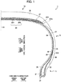
- FIG. 1 is a view showing a half section in a tire-width direction of a tire 1 according to the present embodiment.
- the basic structure of the tire is left/right symmetric in the cross section of the tire-width direction; therefore, a cross-sectional view of the right half is shown herein.
- the reference symbol S1 is the tire equatorial plane.
- the tire equatorial plane S1 is a plane orthogonal to the tire rotation axis, and is positioned in the center of the tire-width direction.
- tire-width direction is a direction parallel to the tire rotation axis, and is the left/right direction of the paper plane of the cross-sectional view in FIG. 1 .
- it is illustrated as the tire-width direction X.
- inner side of tire-width direction is a direction approaching the tire equatorial plane S1, and is the left side of the paper plane in FIG. 1 .
- Outer side of tire-width direction is a direction distancing from the tire equatorial plane S1, and is the right side of the paper plane in FIG. 1 .
- tire-radial direction is a direction perpendicular to the tire rotation axis, and is the vertical direction in the paper plane of FIG. 1 .
- FIG. 1 it is illustrated as the tire-width direction X.
- inner side of tire-width direction is a direction approaching the tire equatorial plane S1, and is the left side of the paper plane in FIG. 1 .
- Outer side of tire-width direction is a direction dis
- tire-radial direction Y it is illustrated as the tire-radial direction Y.
- outer side of tire-radial direction is a direction distancing from the tire rotation axis, and is the upper side of the paper plane in FIG. 1 .
- Inner side of tire-radial direction is a direction approaching the tire rotation axis, and is the lower side of the paper plane in FIG. 1 .
- FIGS. 2 to 8 the same also applies to FIGS. 2 to 8 .
- the tire 1 is a tire for passenger cars, for example, and includes a pair of beads 11 provided at both sides in the tire-width direction, a tread 12 forming the contact patch with the road surface, and a pair of side walls 13 extending between the pair of beads 11 and the tread 12.
- the bead 11 includes an annular bead core 21 formed by wrapping around several times bead wires made of metal coated with rubber, and a bead filler 22 of tapered tip shape extending to the outer side in the tire-radial direction of the bead core 21.
- the bead core 21 is a member which plays a role of fixing a tire filled with air to the rim of a wheel which is not illustrated.
- the bead filler 22 is a member provided in order to raise the rigidity of the bead peripheral part and to ensure high maneuverability and stability, and is configured from rubber of a higher modulus than the surrounding rubber members, for example.
- a carcass ply 23 constituting a ply serving as the skeleton of the tire is embedded inside of the tire 1.
- the carcass ply 23 extends from one bead core to the other bead core. In other words, it is embedded in the tire 1 between the pair of bead cores 21, in a form passing through the pair of side walls 13 and the tread 12.
- the carcass ply 23 includes a ply body 24 which extends from one bead core to the other bead core, and extends between the tread 12 and bead 11, and a ply folding part 25 which is folded around the bead core 21.
- the ply folding part 25 is overlapped with the ply body 24.
- the carcass ply 23 is configured by a plurality of ply cords extending in the tire-width direction.
- a plurality of ply cords is arranged side by side in a tire circumferential direction.
- This ply cord is configured by an insulated organic fiber cord such as polyester or polyamide, or the like, and is covered by rubber.
- At least one ring-shaped steel belt 26 which extends in a circumferential direction of the tire is provided in the outer side in the tire-radial direction of the carcass ply 23.
- the steel belt 26 is configured by a plurality of steel cords covered by rubber.
- a cap ply 27 serving as a belt reinforcement layer is provided.
- the cap ply 27 is configured from an insulating organic fiber layer such as of polyamide fibers, and is covered by rubber.
- the tread rubber 28 is provided at the outer side in the tire-radial direction of the cap ply 27.
- a tread pattern (not illustrated) is provided to the outer surface of the tread rubber 28, and this outer surface serves as a contact patch which contacts with the road surface.
- an inner liner 29 serving as a rubber layer constituting an inside wall surface of the tire 1 is provided to a tire inner cavity side of the carcass ply 23.
- the inner liner 29 is configured by air permeation resistant rubber, whereby the air inside the tire inner cavity is prevented from leaking to outside.
- the side wall rubber 30 constituting the outer wall surface of the tire 1 is provided to the outer side in the tire-width direction of the carcass ply 23.
- This side wall rubber 30 is a portion which bends the most upon the tire exhibiting a cushioning action, and usually flexible rubber having fatigue resistance is adopted therein.
- a chafer 31 is provided on the inner side in the tire-radial direction of the carcass ply 23 provided around the bead core 21 of the bead 11.
- the chafer 31 also extends to the outer side in the tire-width direction of the ply folding part 25 of the carcass ply 23, and rim strip rubber 32 is provided at the outer side in the tire-width direction thereof and the inner side in the tire-radial direction.
- the outer side in the tire-width direction of this rim strip rubber 32 connects with the side wall rubber 30.
- An RFID tag 40 is embedded as an electrical component in the tire 1 of the present embodiment.
- the RFID tag 40 is a passive transponder equipped with an RFID chip and an antenna for performing communication with external equipment, and performs wireless communication with a reader (not illustrated) serving as the external equipment.
- a coil-shaped spring antenna, plate-shaped antenna, and various types of rod-shaped antennas can be used as the antenna.
- it may be an antenna formed by printing a predetermined pattern on a flexible substrate.
- identification information such as a manufacturing number and part number is stored.
- the RFID tag 40 is embedded in a region between the tire-radial direction outside end 22A of the bead filler 22 and the tire-width direction outside end 26A of the steel belt 26.
- the RFID tag 40 is arranged at a position sufficiently distanced from metal bead core 21, which has a possibility of adversely affecting communication.
- the bead core 21 is formed in a ring shape by winding in layers of metal bead wires, and thus is a metal member having a particularly high possibility of adversely affecting communication.
- the RFID tag 40 is arranged to be separated so as not to contact with the steel belt 26. Consequently, no communication disturbance will occur by the antenna length substantially changing due to contact between the antenna of the RFID tag 40 and the steel belt 26. It should be noted that the antenna length of the RFID tag 40 is optimized according to the frequency band, etc. of the radio waves to be used, and if the antenna length changes by contact with a metal member, communication disturbance will occur.
- the cap ply 27 extends more to the outside in the tire-width direction than the steel belt 26. Then, the RFID tag 40 is provided in a region between the tire-radial direction outside end 22A of the bead filler 22, and the tire-width direction outside end 27A of the cap ply 27. According to this configuration, the RFID tag 40 is reliably prevented from contacting with the steel belt 26.
- the RFID tag 40 is embedded in a region between the tire-radial direction outside end 22A of the bead filler 22 and a tire-widest part vicinity A of the side wall 13.
- the RFID tag 40 is arranged at a position far from the metal bead core 21, and also far from the steel belt 26, and thus the possibility of the RFID tag 40 being adversely affected by metal components is low.
- tire-widest part refers to the widest position in the tire-width direction cross section, when assembling the tire to a normal rim, filling with normal internal pressure and establishing an unloaded state not applying load. Then, tire-widest part vicinity A indicates within a range of 20% the cross-sectional height centered around the widest position, i.e. within a range of a position of 10% the cross-sectional height to the tire-radial direction outer side and position of 10% the cross-sectional height to the tire-radial direction inner side, centered around the widest position.
- FIG. 2 is an enlarged cross-sectional view showing around the embedded part of the RFID tag 40.
- the RFID tag 40 is arranged in a state sandwiched between the ply body 24 and ply folding part 25.
- the RFID tag 40 Since the RFID tag 40 is sandwiched between the ply body 24 and ply folding part 25, it is possible to prevent a situation during vulcanization or during use where the antenna of the RFID tag 40 pushes the side wall rubber 30 and/or inner liner 29 which are the rubber structure of the tire 1, and stress concentrates on this portion. In addition, it is possible to prevent stress concentration between the antenna of the RFID tag 40 and the side wall rubber 30 and/or inner liner 29, which are the rubber structure of the tire 1, without using additional members.
- the RFID tag 40 is mounted before the vulcanization process in the manufacturing process of tires.
- the RFID tag 40 is mounted to the ply body 24 or ply folding part 25 of the carcass ply 23 prior to the coating rubber being vulcanized.
- the coating rubber of the carcass ply 23 is in a state of raw rubber prior to vulcanization, it is possible to paste the RFID tag 40 to the carcass ply 23 employing the adhesiveness thereof. Alternatively, it may be pasted using an adhesive or the like.
- the RFID tag 40 is interposed by the carcass ply 23.
- the green tire in which the respective constituent members including the RFID tag 40 are assembled is vulcanized in a vulcanization step to manufacture the tire.
- the assembly work of the RFID tag 40 in the manufacturing process of the tire is easy.
- the RFID tag 40 embedded in the tire when including an antenna, often has a longitudinal direction, as shown as the RFID tag 40 in FIG. 9 described later. It is preferable for such an RFID tag 40 to be embedded in the tire 1, so that the longitudinal direction thereof is a direction of the tangential line to the circumferential direction of the tire, i.e. direction orthogonal to the paper plane in the cross-sectional views of FIGS. 1 and 2 . By embedding in this way, stress is hardly applied to the RFID tag 40, when the tire deforms.
- the RFID tag 40 may be interposed between the ply body 24 and ply folding part 25 in a state covered by a protective member of rubber or the like; however, it may be interposed directly by the ply body 24 and ply folding part 25 without covering by the protective member.
- the RFID tag 40 is arranged in a state interposed by the ply body 24 and ply folding part 25; however, in a case of the ply being configured by a plurality of plies, for example, case of configuring by an up ply (inside carcass ply) and down ply (outside carcass ply), the RFID tag 40 may be arranged in a state interposed between the up ply and down ply, for example.
- the RFID tag 40 is embedded in the tire as an electronic component
- the electronic component embedded in the tire is not limited to an RFID tag.
- it may be various electronic components such as a sensor which carries out wireless communication.
- the electronic component handles electrical information such as sending and receiving of electrical signals, there is a possibility of the performance declining due to metal components being present in the vicinity thereof. Consequently, even in the case of embedding various electronic components in a tire, it is possible to obtain the effects of the present invention.
- the electronic component may be a piezoelectric element or strain sensor.
- FIG. 3 is a view showing a half section in the tire-width direction of the tire 2 of a modified example of the present embodiment.
- FIG. 4 is an enlarged cross-sectional view showing around the embedded part of the RFID tag 40 in the tire 2 of FIG. 3 .
- the RFID tag 40 may be arranged in the tire-widest part vicinity A of the side wall 13, as shown in the present modified example.
- tire-widest part refers to the widest position in the tire-width direction cross section, when assembling the tire to a normal rim, filling with normal internal pressure establishing an unloaded state not applying load.
- the RFID tag 40 is arranged at a position far from the metal bead core 21, and also far from the steel belt 26; therefore, the RFID tag 40 will not be adversely affected by metal components.
- FIG. 5 is a view showing a half section in the tire-width direction of the tire 3 in the present embodiment.
- FIG. 6 is an enlarged cross-sectional view showing around an embedded part of the RFID tag 40 in the tire 3 of FIG. 5 .
- the RFID tag 40 serving as the electronic component is arranged between the carcass ply 23 and the inner liner 29. More specifically, it is arranged between the ply body 24 of the carcass ply 23 and the inner liner 29.
- the RFID tag 40 is embedded in a region between the tire-radial direction outside end 22A of the bead filler 22 and the tire-width direction outside end 26A of the steel belt 26. More specifically, the RFID tag 40 is embedded in a tire-widest part vicinity A of the side wall 13.
- the RFID tag 40 can be arranged at a position sufficiently distanced from the metal bead core 21, which is a position not contacting the steel belt 26, it is possible to prevent deterioration in the communication state of the RFID tag 40.
- the RFID tag 40 is hardly affected by distortion of the tire, etc. while travelling, due to the movement being restricted by the fiber layer constituting the carcass ply 23. Consequently, it is possible to improve the durability of the RFID tag 40 by way of existing components, without using additional components.
- the shock protection also improves. In other words, even if the tire receives external shock, since the distance from the outer wall surface of the tire 1 until the RFID tag 40 is far, and since the carcass ply 23 exists between the outer wall surface of the tire 1 and the RFID tag 40, the RFID tag 40 will be protected.
- the RFID tag 40 is arranged between the carcass ply 23 and the inner liner 29. Consequently, it is hardly affected by distortion of the tire, etc. while travelling, and thus it is possible to improve the durability of the RFID tag 40. In addition, since the distance from the outer wall surface of the tire 3 until the RFID tag 40 becomes far, it is possible to improve impact protection.
- FIG. 7 is a view showing a half section in the tire-width direction of the tire 4 in the present embodiment.
- FIG. 8 is an enlarged cross-sectional view around an embedded part of the RFID tag 40 in the tire 4 of FIG. 7 .
- the RFID tag 40 serving as an electronic component is arranged between the carcass ply 23 and the side wall rubber 30. More specifically, it is arranged between the ply folding part 25 of the carcass ply 23 and the side wall rubber 30.
- the RFID tag 40 is embedded in a region between the tire-radial direction outside end 22A of the bead filler 22 and the tire-width direction outside end 26A of the steel belt 26. More specifically, the RFID tag 40 is embedded in the tire-widest part vicinity A of the side wall 13.
- the RFID tag 40 can be arranged at a position sufficiently distanced from the metal bead core 21, which is a position not contacting the steel belt 26, it is possible to prevent deterioration in the communication state of the RFID tag 40.
- the RFID tag 40 is arranged between the carcass ply 23 and the side wall rubber 30. Consequently, since the distance from the outer wall surface of the tire 4 until the RFID tag 40 becomes shorter, it is possible to achieve an improvement in communicability.
- FIG. 9A is a view showing the RFID tag 40 covered by the protective member 43 which is constituted from a rubber sheet.
- the RFID tag 40 is covered by a rubber sheet 431 described later to be hidden.
- FIG. 9B is a cross-sectional view along the line b-b in FIG. 9A
- FIG. 9C is a cross-sectional view along the line c-c in FIG. 9A .
- the RFID tag 40 is covered by the protective member 43, as shown in FIG. 9 .
- a configuration using the RFID tag 40 protected by the protective member 43 is also applicable to the tires of any embodiment among the first to third embodiments.
- the RFID tag 40 includes an RFID chip 41 and antenna 42 for performing communication with external equipment.
- the antenna 42 a coil-shaped spring antenna, plate-shaped antenna, and various types of rod-shaped antennas can be used.
- it may be an antenna formed by printing a predetermined pattern on a flexible substrate.
- a coil-shaped spring antenna is the most preferable.
- the protective member 43 is configured from two rubber sheets 431, 432 which protect by sandwiching the RFID tag 40.
- the protective member 43 is configured by rubber of a predetermined modulus, for example.
- the modulus indicates 100% elongation modulus (M100) under a 23°C atmosphere, measured in accordance with "3.7 stress at a given elongation, S" of JIS K6251:2010.
- rubber at least having a higher modulus than the side wall rubber 30 is used.
- the modulus of the side wall rubber 30 it is preferable to use rubber of a modulus 1.1 to 2 times as the rubber used in the protective member 43.
- rubber having a higher modulus than the side wall rubber 30 or the inner liner 29 as the rubber adopted in the protective member 43, since the rigidity changes stepwise in the order of RFID tag 40, protective member 43 side wall rubber 30 or inner liner 29 in the embodiments shown in FIGS. 5 to 8 , for example, it is possible to prevent excessive stress from generating within the rubber structure at the embedded part of the RFID tag 40, in the case of the tire deforming.
- the RFID tag 40 is arranged in a region between the side wall rubber 30 and carcass ply 23, when viewing in the tire-width direction. Therefore, the modulus of the protective member 43 may be set to a value higher than the modulus of the side wall rubber 30 and lower than the modulus of the coating rubber of the carcass ply 23. In the case of the modulus within the tire coming to change stepwise, and the tire deforming, it is thereby possible to prevent excessive stress from generated within the rubber structure at the embedded part of the RFID tag 40. In other words, it is possible to suppress the generation of stress.
- the RFID tag 40 is arranged in a region between the inner liner 29 and the carcass ply 23, when viewing in the tire-width direction. Therefore, the modulus of the protective member 43 may be set to a value higher than the modulus of the inner liner 29, and lower than the modulus of the coating rubber of the carcass ply 23. In the case of the modulus within the tire coming to change stepwise, and the tire deforming, it is thereby possible to prevent excessive stress from generated within the rubber structure at the embedded part of the RFID tag 40. In other words, it is possible to suppress the generation of stress.
- the modulus of the inner liner 29 may be a modulus on the same order as the modulus of the side wall rubber 30.
- the protective member 43 may be configured from a short-fiber filler mixed rubber.
- the short-fiber filler for example, it is possible to use insulating short fibers like organic short fibers such as aramid short fibers and cellulose short fibers; inorganic short fibers such as ceramic short fibers as in alumina short fiber, and glass short fiber. By mixing such short-fiber fillers into rubber, it is possible to raise the strength of the rubber.
- a rubber sheet in the vulcanized state may be used as the protective member 43. The rubber sheet in a vulcanized state does not plastically deform as raw rubber, and thus can appropriately protect the RFID tag 40.
- an organic fiber layer from polyester fibers or polyamide fibers may be provided. It is also possible to embed an organic fiber layer in the two rubber sheets 431, 432.
- the RFID tag 40 covered by the rubber sheets can be installed very easily. For example, at a desired position of a member such as the carcass ply 23, inner liner 29 and side wall rubber 30 prior to vulcanization, it is possible to appropriately paste the RFID tag 40 covered by the rubber sheets using the adhesiveness of the raw rubber. In addition, by also establishing the rubber sheets as raw rubber prior to vulcanization, it is possible to more easily paste by employing the adhesiveness of the rubber sheet itself as well.
- the protective member 43 is not limited to the form configured by two rubber sheets, and can adopt various forms.
- at least one rubber sheet constituting the protective member so long as covering at least part of the RFID tag 40, can obtain effects such as an improvement in workability in the manufacturing process and stress mitigation.
- it may be a configuration wrapping one rubber sheet around the entire circumference of the RFID tag 40, or a configuration attaching the protective member in the form of a potting agent of high viscosity along the entire circumference of the RFID tag 40. Even if such a configuration, it will be possible to appropriately protect the RFID tag 40.
- the RFID tag 40 comes to be sandwiched between the ply body 24 and the ply folding part 25 in a state covered by the protective member 43.
- the RFID tag 40 is protected even under the situation of the RFID tag 40 receiving stress from the ply body 24 and ply folding part 25 moving relatively. Consequently, the durability of the RFID tag 40 further improves.
- the tire-widest part vicinity A is a portion which relatively greatly bends during tire deformation.
- the protective member 43 it is possible to raise the durability of the RFID tag 40, even in a case of embedding the RFID tag 40 in such a portion.
- the second and third embodiment it is also possible to adopt a configuration embedding the RFID tag 40 protected by the protective member 43 in the tire. Also in this case, the durability of the RFID tag 40 improves.
- the protective member 43 it becomes possible to prevent the antenna 42 of the RFID tag 40 from directly pushing the side wall rubber 30 or inner liner 29 which are the rubber structure of the tire, during vulcanization or during usage.
- the RFID tag covered by the rubber sheet in the vulcanized state may be attached to a constituent member of the tire prior to vulcanization, e.g., carcass ply 23.
- the protective member 43 may be provided only to one side of the RFID tag 40.
- a rubber sheet and/or fiber layer may be provided as the protective member only to the inner side in the tire-width direction of the RFID tag 40, i.e. side of the inner liner 29, in the second embodiment.
- a rubber sheet and/or fiber layer may be provided as the protective member only to the outer side in the tire-width direction of the RFID tag 40, i.e. side of the side wall.
- a rubber sheet and/or fiber layer may be provided as the protective member only to the outer side in the tire-width direction of the RFID tag 40, i.e. side of the carcass ply 23, in the second embodiment.
- a rubber sheet and/or fiber layer may be provided as the protective member only to the inner side in the tire-width direction of the RFID tag 40, i.e.
- a rubber sheet and/or fiber layer may be provided as the protective member only to the outer side in the tire-width direction of the RFID tag 40, or only to the inner side in the tire-width direction, in the first embodiment, for example.
- the protective member 43 only to one side of the RFID tag 40, it is possible to make the overall thickness thin.
- the RFID tag 40 covered by the protective member 43 is embedded in the tire so that the longitudinal direction thereof becomes the direction of the tangential line relative to the circumferential direction of the tire, i.e. direction orthogonal to the paper plane in the cross-sectional view of FIGS. 1 to 8 .
- the rubber sheets 431, 432 are embedded in the tire in a form such that aligns in the tire-width direction.
- one surface of either one of the rubber sheets 431, 432 is pasted to a constituent member of the tire prior to vulcanization, e.g., the carcass ply 23.
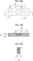
- FIG. 10A is a view showing the RFID tag 40 protected by a protective member 44.
- the RFID tag 40 is covered by a rubber sheet 441 described later and is hidden.
- FIG. 10B is a cross-sectional view along the line b-b in FIG. 10A
- FIG. 10C is a cross-sectional view along the line c-c in FIG. 10A .
- the RFID tag 40 serving as the electronic component is arranged between the carcass ply 23 and the inner liner 29. Then, the RFID tag 40 is covered by a protective member configured from two rubber sheets, similarly to the fourth embodiment. However, in the present embodiment, the thicknesses of the two rubber sheets constituting the protective member 44 are different. More similarly, the rubber sheet 441 on the tire inner cavity side, i.e. side of the inner liner 29, is formed thicker than the rubber sheet 442 on the tire outer surface side, i.e. side of the carcass ply 23.
- the thickness of the rubber sheet 441 on the side of the inner liner 29 is formed thickly in order to more strongly protect the side of the inner liner 29, it is also possible to adopt another configuration for more strongly protecting the side of the inner liner 29.
- the modulus of the rubber sheet 441 on the side of the inner liner 29 may be set to a modulus higher than the modulus of the rubber sheet 442 on the side of the carcass ply 23.
- the relationship of magnitudes of the modulus of each member it is preferable for the relationship of magnitudes of the modulus of each member to be in the order of "rubber sheet 441" > "rubber sheet 442” > "side wall rubber 30".
- the rubber sheet 441 may be constituted by short-fiber filler mixed rubber.
- the short-fiber filler for example, it is possible to use insulating short fibers like organic short fibers such as aramid short fibers and cellulose short fibers; inorganic short fibers such as ceramic short fibers as in alumina short fiber, and glass short fiber. By mixing such short-fiber fillers into rubber, it is possible to raise the strength of the rubber.
- the rubber sheet 441 a rubber sheet in the vulcanized state may be used as the rubber sheet 441. The rubber sheet in a vulcanized state does not plastically deform as does raw rubber, and thus can appropriately protect the RFID tag 40.
- an organic fiber layer such as of polyester fiber or polyamide fiber may be provided to the rubber sheet 441. In these cases, it is also possible to establish the thicknesses of the rubber sheets 441 and 442 as the same thickness.
- the rubber sheet 441 on the inner side in the tire-width direction i.e. side of the inner liner 29 is formed thicker than the rubber sheet 442 on the outer side in the tire-width direction, i.e. side of the carcass ply 23. Since the side of the inner liner 29 is thereby more strongly protected, it is possible to protect the antenna 42 of the RFID tag 40 from strongly pushing the inner liner 29 during vulcanization and during use.
- side wall rubber 60 plays a function as a protective member. More specifically, in the present embodiment, similarly to the third embodiment shown in FIGS. 7 and 8 , the RFID tag 40 serving as the electronic component is arranged between the carcass ply 23 and the side wall rubber 60. Then, in the present embodiment, rubber of a modulus higher than the inner liner 29 is used as the side wall rubber 60. It is thereby possible for the side wall rubber 60 to function as a protective member of the RFID tag 40, and protect the RFID tag 40. Consequently, it is possible to protect the RFID tag 40 by a simple configuration, without increasing the number of members.
- the RFID tag 40 is arranged between the carcass ply 23 and the side wall rubber 60, and the side wall rubber 60 of higher modulus than the inner liner 29 functions as a protective member of the RFID tag 40. Consequently, it is possible to protect the RFID tag 40 by way a simple configuration, without increasing the number of components.
- the tire of the present invention can be adopted as various types of tires such as for cars, light trucks, trucks and buses, it is particularly suitable as a tire for passenger cars. It should be noted that the present invention is not to be limited to the above-mentioned embodiments, and that even when carrying out modifications, improvements, etc. within a scope capable of achieving the object of the present invention, it is encompassed by the scope of the present invention.
Landscapes
- Engineering & Computer Science (AREA)
- Mechanical Engineering (AREA)
- Computer Hardware Design (AREA)
- Microelectronics & Electronic Packaging (AREA)
- Physics & Mathematics (AREA)
- General Physics & Mathematics (AREA)
- Theoretical Computer Science (AREA)
- Tires In General (AREA)
Abstract
Description
- The present invention relates to a tire into which an electronic component is embedded.
- Conventionally, a tire embedding an electronic component such as an RFID tag has been known. With such a tire, it is possible to carry out production management of the tire, usage history management, etc. by the RFID tag embedded in the tire and a reader as external equipment carrying out communication. For example,
Patent Document 1 discloses a tire embedding an RF tag in the vicinity of a stiffener. - Patent Document 1: Japanese Unexamined Patent Application, Publication No.
2016-37236 - According to the technology illustrated in
Patent Document 1, it is possible to carry out production management, shipping management, usage history management, etc. of tires. However, with the technology illustrated inPatent Document 1, the RF tag is arranged in the vicinity of a stiffener adjacent to a metal bead core. Consequently, with an electronic device such as the RF tag having a communication function, there is a possibility of the communication state thereof being affected by the metal bead core and becoming unstable. In other words, there is a possibility of the electronic device no longer being able to exhibit the original function thereof. - The present invention has been made taking account of the above-mentioned problem, and an object thereof is to provide a tire which can maintain the performance of the electronic component, by arranging the electronic device at a position distanced from metal components.
- A tire (for example,
tire end 22A of the bead filler) of the bead filler and a tire-width direction outside end (for example, the tire-width direction outsideend 26A of the steel belt) of the steel belt. - According to a second aspect of the present invention, the tire as described in the first aspect may further include: a cap ply (for example, the cap ply 27) at an outer side in the tire-radial direction of the steel belt, in which a tire-width direction outside end (for example, the tire-width direction outside
end 27A of the cap ply) of the cap ply may extend more to an outer side in the tire-width direction than the tire-width direction outside end of the steel belt; and the electronic component may be embedded in a region between the tire-radial direction outside end of the bead filler and the tire-width direction outside end of the cap ply. - According to a third aspect of the present invention, the tire as described in the first aspect may further include: a side wall (for example, the side wall 13) which extends between the bead and the tread, in which the electronic component may be embedded in a region between a tire-widest part vicinity (for example, the tire-widest part vicinity A) of the side wall and the tire-radial direction outside end of the bead filler.
- According to a fourth aspect of the present invention, in the tire as described in the third aspect, the electronic component may be embedded in the tire-widest part vicinity of the side wall.
- According to a fifth aspect of the present invention, the tire as described in the third or fourth aspect may further include: a carcass ply (for example, the carcass ply 23) which extends from one bead core to another bead core, in which the carcass ply may have an overlapped region at the side wall, and the electronic component may be arranged between the carcass ply that is overlapped.
- According to a sixth aspect of the present invention, in the tire as described in the fifth aspect, the carcass ply that is overlapped may be formed by a ply body (for example, the ply body 24) extending from the one bead core to the other bead core, and a ply folding part (for example, the ply folding part 25) that is folded back around the bead core and is overlapped with the ply body.
- According to a seventh aspect of the present invention, the tire as described in any one of the first to fourth aspects may further include: a carcass ply which is at least one layer extending from one bead core to another bead core; and an inner liner (for example, the inner liner 29) provided to a tire inner cavity side of the carcass ply, in which the electronic component may be arranged between the carcass ply and the inner liner.
- According to an eighth aspect of the present invention, the tire as described in any one of the first to fourth aspects may further include: a carcass ply which is at least one layer extending from one bead core to another bead core; and side wall rubber (for example, the side wall rubber 30) provided to an outer side in the tire-width direction of the carcass ply, the electronic component may be arranged between the carcass ply and the side wall rubber.
- According to a ninth aspect of the present invention, in the tire as described in any one of the first to eighth aspects, at least one rubber sheet (for example, the
rubber sheet - According to a tenth aspect of the present invention, the tire as described in the ninth aspect may further include: a carcass ply which is at least one layer extending from one bead core to another bead core; an inner liner provided to an inner side in the tire-width direction of the carcass ply; and side wall rubber provided to an outer side in the tire-width direction of the carcass ply, in which the rubber sheet may be configured from rubber of higher modulus than the side wall rubber, or a short-fiber filler mixed rubber.
- According to an eleventh aspect of the present invention, the tire as described in the ninth aspect may further include: a carcass ply which is at least one layer extending from one bead core to another bead core; an inner liner provided to an inner side in the tire-width direction of the carcass ply; and side wall rubber provided to an outer side in the tire-width direction of the carcass ply, in which the rubber sheet may be configured from rubber of higher modulus than the side wall rubber or the inner liner, and lower modulus than coating rubber of the carcass ply.
- According to the present invention, it is possible to provide a tire which can maintain the performance of the electronic component, by arranging the electronic device at a position distanced from metal components.
-
-
FIG. 1 is a view showing a half section in a tire-width direction of a tire according to a first embodiment of the present invention; -
FIG. 2 is a partially enlarged view of a tire according to the first embodiment of the present invention; -
FIG. 3 is a view showing a half section in a tire-width direction of a tire according to a modified example of the first embodiment of the present invention; -
FIG. 4 is a partially enlarged cross-sectional view of a tire according to a modified example of the first embodiment of the present invention; -
FIG. 5 is a view showing a half section in the tire-width direction of a tire according to a second embodiment of the present invention; -
FIG. 6 is a partially enlarged cross-sectional view of the tire according to the second embodiment of the present invention; -
FIG. 7 is a view showing a half section in the tire-width direction of a tire according to a third embodiment of the present invention; -
FIG. 8 is a partially enlarged cross-sectional view of the tire according to the third embodiment of the present invention; -
FIG. 9A is a view showing an RFID tag which is protected by a protective member in a tire according to a fourth embodiment of the present invention; -
FIG. 9B is a view showing the b-b cross section inFIG. 9A ; -
FIG. 9C is a view showing the c-c cross section inFIG. 9A ; -
FIG. 10A is a view showing an RFID tag protected by a protective member in a tire according to a fifth embodiment of the present invention; -
FIG. 10B is a view showing the b-b cross section inFIG. 10A ; -
FIG. 10C is a view showing the c-c cross section inFIG. 10A ; and -
FIG. 11 is a view showing a half section in the tire-width direction of a tire according to a sixth embodiment. - Hereinafter, a first embodiment of the present invention will be explained while referencing the drawings.
FIG. 1 is a view showing a half section in a tire-width direction of atire 1 according to the present embodiment. The basic structure of the tire is left/right symmetric in the cross section of the tire-width direction; therefore, a cross-sectional view of the right half is shown herein. In the drawings, the reference symbol S1 is the tire equatorial plane. The tire equatorial plane S1 is a plane orthogonal to the tire rotation axis, and is positioned in the center of the tire-width direction. Herein, tire-width direction is a direction parallel to the tire rotation axis, and is the left/right direction of the paper plane of the cross-sectional view inFIG. 1 . InFIG. 1 , it is illustrated as the tire-width direction X. Then, inner side of tire-width direction is a direction approaching the tire equatorial plane S1, and is the left side of the paper plane inFIG. 1 . Outer side of tire-width direction is a direction distancing from the tire equatorial plane S1, and is the right side of the paper plane inFIG. 1 . In addition, tire-radial direction is a direction perpendicular to the tire rotation axis, and is the vertical direction in the paper plane ofFIG. 1 . InFIG. 1 , it is illustrated as the tire-radial direction Y. Then, outer side of tire-radial direction is a direction distancing from the tire rotation axis, and is the upper side of the paper plane inFIG. 1 . Inner side of tire-radial direction is a direction approaching the tire rotation axis, and is the lower side of the paper plane inFIG. 1 . The same also applies toFIGS. 2 to 8 . - The
tire 1 is a tire for passenger cars, for example, and includes a pair ofbeads 11 provided at both sides in the tire-width direction, atread 12 forming the contact patch with the road surface, and a pair ofside walls 13 extending between the pair ofbeads 11 and thetread 12. - The
bead 11 includes anannular bead core 21 formed by wrapping around several times bead wires made of metal coated with rubber, and abead filler 22 of tapered tip shape extending to the outer side in the tire-radial direction of thebead core 21. Thebead core 21 is a member which plays a role of fixing a tire filled with air to the rim of a wheel which is not illustrated. Thebead filler 22 is a member provided in order to raise the rigidity of the bead peripheral part and to ensure high maneuverability and stability, and is configured from rubber of a higher modulus than the surrounding rubber members, for example. - A carcass ply 23 constituting a ply serving as the skeleton of the tire is embedded inside of the
tire 1. The carcass ply 23 extends from one bead core to the other bead core. In other words, it is embedded in thetire 1 between the pair ofbead cores 21, in a form passing through the pair ofside walls 13 and thetread 12. As shown inFIG. 1 , the carcass ply 23 includes aply body 24 which extends from one bead core to the other bead core, and extends between thetread 12 andbead 11, and aply folding part 25 which is folded around thebead core 21. In the present embodiment, theply folding part 25 is overlapped with theply body 24. The carcass ply 23 is configured by a plurality of ply cords extending in the tire-width direction. In addition, a plurality of ply cords is arranged side by side in a tire circumferential direction. This ply cord is configured by an insulated organic fiber cord such as polyester or polyamide, or the like, and is covered by rubber. - In the
tread 12, at least one ring-shapedsteel belt 26 which extends in a circumferential direction of the tire is provided in the outer side in the tire-radial direction of thecarcass ply 23. Thesteel belt 26 is configured by a plurality of steel cords covered by rubber. By providing thesteel belts 26, the rigidity of the tire is ensured, and the contact state of the road surface with thetread 12 improves. In the present embodiment, although two layers ofsteel belts steel belts 26 is not limited thereto. - At the outer side in the tire-radial direction of the
steel belt 26, acap ply 27 serving as a belt reinforcement layer is provided. The cap ply 27 is configured from an insulating organic fiber layer such as of polyamide fibers, and is covered by rubber. By providing thecap ply 27, it is possible to achieve an improvement in durability and a reduction in road noise while travelling. - The
tread rubber 28 is provided at the outer side in the tire-radial direction of thecap ply 27. A tread pattern (not illustrated) is provided to the outer surface of thetread rubber 28, and this outer surface serves as a contact patch which contacts with the road surface. - In the
bead 11,side wall 13 andtread 12, aninner liner 29 serving as a rubber layer constituting an inside wall surface of thetire 1 is provided to a tire inner cavity side of thecarcass ply 23. Theinner liner 29 is configured by air permeation resistant rubber, whereby the air inside the tire inner cavity is prevented from leaking to outside. - In the
side wall 13, theside wall rubber 30 constituting the outer wall surface of thetire 1 is provided to the outer side in the tire-width direction of thecarcass ply 23. Thisside wall rubber 30 is a portion which bends the most upon the tire exhibiting a cushioning action, and usually flexible rubber having fatigue resistance is adopted therein. - A
chafer 31 is provided on the inner side in the tire-radial direction of the carcass ply 23 provided around thebead core 21 of thebead 11. Thechafer 31 also extends to the outer side in the tire-width direction of theply folding part 25 of thecarcass ply 23, andrim strip rubber 32 is provided at the outer side in the tire-width direction thereof and the inner side in the tire-radial direction. The outer side in the tire-width direction of thisrim strip rubber 32 connects with theside wall rubber 30. - An
RFID tag 40 is embedded as an electrical component in thetire 1 of the present embodiment. TheRFID tag 40 is a passive transponder equipped with an RFID chip and an antenna for performing communication with external equipment, and performs wireless communication with a reader (not illustrated) serving as the external equipment. As the antenna, a coil-shaped spring antenna, plate-shaped antenna, and various types of rod-shaped antennas can be used. For example, it may be an antenna formed by printing a predetermined pattern on a flexible substrate. In a storage part inside the RFID chip, identification information such as a manufacturing number and part number is stored. - As shown in
FIG. 1 , theRFID tag 40 is embedded in a region between the tire-radial direction outsideend 22A of thebead filler 22 and the tire-width direction outsideend 26A of thesteel belt 26. In other words, theRFID tag 40 is arranged at a position sufficiently distanced frommetal bead core 21, which has a possibility of adversely affecting communication. Herein, thebead core 21 is formed in a ring shape by winding in layers of metal bead wires, and thus is a metal member having a particularly high possibility of adversely affecting communication. - In addition, the
RFID tag 40 is arranged to be separated so as not to contact with thesteel belt 26. Consequently, no communication disturbance will occur by the antenna length substantially changing due to contact between the antenna of theRFID tag 40 and thesteel belt 26. It should be noted that the antenna length of theRFID tag 40 is optimized according to the frequency band, etc. of the radio waves to be used, and if the antenna length changes by contact with a metal member, communication disturbance will occur. - Herein, adding to the present embodiment, the cap ply 27 extends more to the outside in the tire-width direction than the
steel belt 26. Then, theRFID tag 40 is provided in a region between the tire-radial direction outsideend 22A of thebead filler 22, and the tire-width direction outsideend 27A of thecap ply 27. According to this configuration, theRFID tag 40 is reliably prevented from contacting with thesteel belt 26. - Further adding to the present embodiment, the
RFID tag 40 is embedded in a region between the tire-radial direction outsideend 22A of thebead filler 22 and a tire-widest part vicinity A of theside wall 13. In other words, theRFID tag 40 is arranged at a position far from themetal bead core 21, and also far from thesteel belt 26, and thus the possibility of theRFID tag 40 being adversely affected by metal components is low. - Herein, tire-widest part refers to the widest position in the tire-width direction cross section, when assembling the tire to a normal rim, filling with normal internal pressure and establishing an unloaded state not applying load. Then, tire-widest part vicinity A indicates within a range of 20% the cross-sectional height centered around the widest position, i.e. within a range of a position of 10% the cross-sectional height to the tire-radial direction outer side and position of 10% the cross-sectional height to the tire-radial direction inner side, centered around the widest position. Herein, cross-sectional height is a numerical value decided by the tire size, for example, in the case of a tire of size 195/65 R15, "cross-sectional height = called width x ellipticity = 195 x 0.65 = 126.75 mm".
-
FIG. 2 is an enlarged cross-sectional view showing around the embedded part of theRFID tag 40. As shown inFIG. 2 , in the present embodiment, theRFID tag 40 is arranged in a state sandwiched between theply body 24 and ply foldingpart 25. - Since the
RFID tag 40 is sandwiched between theply body 24 and ply foldingpart 25, it is possible to prevent a situation during vulcanization or during use where the antenna of theRFID tag 40 pushes theside wall rubber 30 and/orinner liner 29 which are the rubber structure of thetire 1, and stress concentrates on this portion. In addition, it is possible to prevent stress concentration between the antenna of theRFID tag 40 and theside wall rubber 30 and/orinner liner 29, which are the rubber structure of thetire 1, without using additional members. - Herein, the
RFID tag 40 is mounted before the vulcanization process in the manufacturing process of tires. In the present embodiment, theRFID tag 40 is mounted to theply body 24 or ply foldingpart 25 of the carcass ply 23 prior to the coating rubber being vulcanized. At this time, since the coating rubber of the carcass ply 23 is in a state of raw rubber prior to vulcanization, it is possible to paste theRFID tag 40 to the carcass ply 23 employing the adhesiveness thereof. Alternatively, it may be pasted using an adhesive or the like. After pasting theRFID tag 40, by overlapping theply body 24 and ply foldingpart 25, theRFID tag 40 is interposed by thecarcass ply 23. Subsequently, the green tire in which the respective constituent members including theRFID tag 40 are assembled is vulcanized in a vulcanization step to manufacture the tire. In this way, in the present embodiment, since it is possible to paste theRFID tag 40 to the carcass ply 23 covered by the raw rubber having rigidity and having adhesiveness during tire manufacture, the assembly work of theRFID tag 40 in the manufacturing process of the tire is easy. - It should be noted that the
RFID tag 40 embedded in the tire, when including an antenna, often has a longitudinal direction, as shown as theRFID tag 40 inFIG. 9 described later. It is preferable for such anRFID tag 40 to be embedded in thetire 1, so that the longitudinal direction thereof is a direction of the tangential line to the circumferential direction of the tire, i.e. direction orthogonal to the paper plane in the cross-sectional views ofFIGS. 1 and2 . By embedding in this way, stress is hardly applied to theRFID tag 40, when the tire deforms. - It should be noted that the
RFID tag 40 may be interposed between theply body 24 and ply foldingpart 25 in a state covered by a protective member of rubber or the like; however, it may be interposed directly by theply body 24 and ply foldingpart 25 without covering by the protective member. - It should be noted that, in the present embodiment, the
RFID tag 40 is arranged in a state interposed by theply body 24 and ply foldingpart 25; however, in a case of the ply being configured by a plurality of plies, for example, case of configuring by an up ply (inside carcass ply) and down ply (outside carcass ply), theRFID tag 40 may be arranged in a state interposed between the up ply and down ply, for example. - It should be noted that, in the present embodiment, although the
RFID tag 40 is embedded in the tire as an electronic component, the electronic component embedded in the tire is not limited to an RFID tag. For example, it may be various electronic components such as a sensor which carries out wireless communication. In addition, since the electronic component handles electrical information such as sending and receiving of electrical signals, there is a possibility of the performance declining due to metal components being present in the vicinity thereof. Consequently, even in the case of embedding various electronic components in a tire, it is possible to obtain the effects of the present invention. For example, the electronic component may be a piezoelectric element or strain sensor. -
FIG. 3 is a view showing a half section in the tire-width direction of thetire 2 of a modified example of the present embodiment.FIG. 4 is an enlarged cross-sectional view showing around the embedded part of theRFID tag 40 in thetire 2 ofFIG. 3 . TheRFID tag 40 may be arranged in the tire-widest part vicinity A of theside wall 13, as shown in the present modified example. Herein, tire-widest part refers to the widest position in the tire-width direction cross section, when assembling the tire to a normal rim, filling with normal internal pressure establishing an unloaded state not applying load. - Even in this case, the
RFID tag 40 is arranged at a position far from themetal bead core 21, and also far from thesteel belt 26; therefore, theRFID tag 40 will not be adversely affected by metal components. - According to the
tire 1 of the present embodiment, the following effects are exerted. - (1) With the
tire 1 according to the present embodiment, theRFID tag 40 is embedded in a region between the tire-radial direction outsideend 22A of thebead filler 22 and the tire-width direction outsideend 26A of thesteel belt 26. Since it is thereby possible to arrange theRFID tag 40 at a position distanced from metal components such as thebead core 21, the performance of the communication function, etc. of theRFID tag 40 can be maintained. - (2) With the
tire 1 according to the present embodiment, theRFID tag 40 is embedded in a region between the tire-radial direction outsideend 22A of thebead filler 22 and the tire-width direction outsideend 27A of thecap ply 27. It is thereby possible to reliably prevent theRFID tag 40 from contacting with thesteel belt 26. Consequently, it is possible to keep the performance such as of the communication function of theRFID tag 40. - (3) With the
tire 1 according to the present embodiment, theRFID tag 40 is embedded in a region between the tire-widest part vicinity A of theside wall 13 and the tire-radial direction outsideend 22A of thebead filler 22. Since theRFID tag 40 is thereby arranged at a position far from themetal bead core 21, and also far from thesteel belt 26, the possibility of theRFID tag 40 being adversely affected by metal components becomes very low. - (4) With the
tire 1 according to the present embodiment, theRFID tag 40 is embedded in the tire-widest part vicinity A of theside wall 13. Since theRFID tag 40 is thereby arranged at a position far from themetal bead core 21, and also far from thesteel belt 26, the possibility of theRFID tag 40 being adversely affected by metal components becomes very low. - (5) The
tire 1 according to the present embodiment has a region in which the carcass ply 23 overlaps in theside wall 13, and theRFID tag 40 is arranged between the overlappedcarcass ply 23. It is thereby possible to prevent stress concentration between the antenna of theRFID tag 40 and theside wall rubber 30 and/orinner liner 29 which are the rubber structure of thetire 1, during vulcanization and during use. - (6) With the
tire 1 according to the present embodiment, the overlapped carcass ply 23 is configured from theply body 24 extending from onebead core 21 to theother bead core 21, and theply folding part 25 which is folded back around thebead core 21, and overlapped with theply body 24. It is thereby possible to prevent stress concentration between the antenna of theRFID tag 40 and theside wall rubber 30 and/orinner liner 29 which are the rubber structure of thetire 1, during vulcanization and during use. - Next, a tire 3 according to a second embodiment will be explained while referencing
FIGS. 5 and6 . It should be noted that the same reference symbol will be attached for the same configurations as the first embodiment in the following explanation, and detailed explanations thereof will be omitted. -
FIG. 5 is a view showing a half section in the tire-width direction of the tire 3 in the present embodiment.FIG. 6 is an enlarged cross-sectional view showing around an embedded part of theRFID tag 40 in the tire 3 ofFIG. 5 . In the present embodiment, theRFID tag 40 serving as the electronic component is arranged between thecarcass ply 23 and theinner liner 29. More specifically, it is arranged between theply body 24 of thecarcass ply 23 and theinner liner 29. Then, similarly to the first embodiment, theRFID tag 40 is embedded in a region between the tire-radial direction outsideend 22A of thebead filler 22 and the tire-width direction outsideend 26A of thesteel belt 26. More specifically, theRFID tag 40 is embedded in a tire-widest part vicinity A of theside wall 13. - Even if such a configuration, since the
RFID tag 40 can be arranged at a position sufficiently distanced from themetal bead core 21, which is a position not contacting thesteel belt 26, it is possible to prevent deterioration in the communication state of theRFID tag 40. - In addition, according to the present embodiment, the
RFID tag 40 is hardly affected by distortion of the tire, etc. while travelling, due to the movement being restricted by the fiber layer constituting thecarcass ply 23. Consequently, it is possible to improve the durability of theRFID tag 40 by way of existing components, without using additional components. In addition, according to the present embodiment, the shock protection also improves. In other words, even if the tire receives external shock, since the distance from the outer wall surface of thetire 1 until theRFID tag 40 is far, and since the carcass ply 23 exists between the outer wall surface of thetire 1 and theRFID tag 40, theRFID tag 40 will be protected. - According to the tire 3 of the present embodiment, the following effects are exerted in addition to the above (1) to (4) .
- (7) In the present embodiment, the
RFID tag 40 is arranged between thecarcass ply 23 and theinner liner 29. Consequently, it is hardly affected by distortion of the tire, etc. while travelling, and thus it is possible to improve the durability of theRFID tag 40. In addition, since the distance from the outer wall surface of the tire 3 until theRFID tag 40 becomes far, it is possible to improve impact protection. - Next, a
tire 4 according to a third embodiment will be explained while referencingFIGS. 7 and8 . It should be noted that the same reference symbol will be attached for the same configurations as the first embodiment in the following explanation, and detailed explanations thereof will be omitted. -
FIG. 7 is a view showing a half section in the tire-width direction of thetire 4 in the present embodiment.FIG. 8 is an enlarged cross-sectional view around an embedded part of theRFID tag 40 in thetire 4 ofFIG. 7 . In the present embodiment, theRFID tag 40 serving as an electronic component is arranged between thecarcass ply 23 and theside wall rubber 30. More specifically, it is arranged between theply folding part 25 of thecarcass ply 23 and theside wall rubber 30. Then, similarly to the first embodiment, theRFID tag 40 is embedded in a region between the tire-radial direction outsideend 22A of thebead filler 22 and the tire-width direction outsideend 26A of thesteel belt 26. More specifically, theRFID tag 40 is embedded in the tire-widest part vicinity A of theside wall 13. - Even if such a configuration, since the
RFID tag 40 can be arranged at a position sufficiently distanced from themetal bead core 21, which is a position not contacting thesteel belt 26, it is possible to prevent deterioration in the communication state of theRFID tag 40. - In addition, since the distance from the outer wall surface of the
tire 4 until theRFID tag 40 becomes shorter, it is possible to achieve an improvement in communicability. - According to the
tire 4 of the present embodiment, the following effects are exerted in addition to the above (1) to (4) . - (8) In the present embodiment, the
RFID tag 40 is arranged between thecarcass ply 23 and theside wall rubber 30. Consequently, since the distance from the outer wall surface of thetire 4 until theRFID tag 40 becomes shorter, it is possible to achieve an improvement in communicability. - Next, a tire according to a fourth embodiment will be explained while referencing
FIG. 9 . It should be noted that the same reference symbol will be attached for the same configurations as the first to third embodiments in the following explanation, and detailed explanations thereof will be omitted. -
FIG. 9A is a view showing theRFID tag 40 covered by theprotective member 43 which is constituted from a rubber sheet. InFIG. 9A , theRFID tag 40 is covered by arubber sheet 431 described later to be hidden.FIG. 9B is a cross-sectional view along the line b-b inFIG. 9A, and FIG. 9C is a cross-sectional view along the line c-c inFIG. 9A . In the present embodiment, theRFID tag 40 is covered by theprotective member 43, as shown inFIG. 9 . A configuration using theRFID tag 40 protected by theprotective member 43 is also applicable to the tires of any embodiment among the first to third embodiments. - The
RFID tag 40 includes anRFID chip 41 andantenna 42 for performing communication with external equipment. As theantenna 42, a coil-shaped spring antenna, plate-shaped antenna, and various types of rod-shaped antennas can be used. For example, it may be an antenna formed by printing a predetermined pattern on a flexible substrate. When considering the communicability and flexibility, a coil-shaped spring antenna is the most preferable. - The
protective member 43 is configured from tworubber sheets RFID tag 40. - The
protective member 43 is configured by rubber of a predetermined modulus, for example. Herein, the modulus indicates 100% elongation modulus (M100) under a 23°C atmosphere, measured in accordance with "3.7 stress at a given elongation, S" of JIS K6251:2010. - As the rubber adopted in the
protective member 43, rubber at least having a higher modulus than theside wall rubber 30 is used. For example, with the modulus of theside wall rubber 30 as a reference, it is preferable to use rubber of a modulus 1.1 to 2 times as the rubber used in theprotective member 43. In addition, by using rubber having a higher modulus than theside wall rubber 30 or theinner liner 29 as the rubber adopted in theprotective member 43, since the rigidity changes stepwise in the order ofRFID tag 40,protective member 43side wall rubber 30 orinner liner 29 in the embodiments shown inFIGS. 5 to 8 , for example, it is possible to prevent excessive stress from generating within the rubber structure at the embedded part of theRFID tag 40, in the case of the tire deforming. - It should be noted that, in the third embodiment shown in
FIGS. 7 and8 , theRFID tag 40 is arranged in a region between theside wall rubber 30 and carcass ply 23, when viewing in the tire-width direction. Therefore, the modulus of theprotective member 43 may be set to a value higher than the modulus of theside wall rubber 30 and lower than the modulus of the coating rubber of thecarcass ply 23. In the case of the modulus within the tire coming to change stepwise, and the tire deforming, it is thereby possible to prevent excessive stress from generated within the rubber structure at the embedded part of theRFID tag 40. In other words, it is possible to suppress the generation of stress. - It should be noted that, in the second embodiment shown in
FIGS. 5 and6 , theRFID tag 40 is arranged in a region between theinner liner 29 and thecarcass ply 23, when viewing in the tire-width direction. Therefore, the modulus of theprotective member 43 may be set to a value higher than the modulus of theinner liner 29, and lower than the modulus of the coating rubber of thecarcass ply 23. In the case of the modulus within the tire coming to change stepwise, and the tire deforming, it is thereby possible to prevent excessive stress from generated within the rubber structure at the embedded part of theRFID tag 40. In other words, it is possible to suppress the generation of stress. At this time, the modulus of theinner liner 29 may be a modulus on the same order as the modulus of theside wall rubber 30. - In addition, the
protective member 43 may be configured from a short-fiber filler mixed rubber. As the short-fiber filler, for example, it is possible to use insulating short fibers like organic short fibers such as aramid short fibers and cellulose short fibers; inorganic short fibers such as ceramic short fibers as in alumina short fiber, and glass short fiber. By mixing such short-fiber fillers into rubber, it is possible to raise the strength of the rubber. In addition, as theprotective member 43, a rubber sheet in the vulcanized state may be used. The rubber sheet in a vulcanized state does not plastically deform as raw rubber, and thus can appropriately protect theRFID tag 40. In addition, as theprotective member 43, an organic fiber layer from polyester fibers or polyamide fibers may be provided. It is also possible to embed an organic fiber layer in the tworubber sheets - In this way, if configuring the
protective member 43 by two rubber sheets, since it is possible to thinly form theRFID tag 40 including theprotective member 43, it is favorable upon embedding in thetires 1 to 3. In addition, when assembling theRFID tag 40 in the constitutional members of thetires 1 to 3 prior to vulcanization, theRFID tag 40 covered by the rubber sheets can be installed very easily. For example, at a desired position of a member such as thecarcass ply 23,inner liner 29 andside wall rubber 30 prior to vulcanization, it is possible to appropriately paste theRFID tag 40 covered by the rubber sheets using the adhesiveness of the raw rubber. In addition, by also establishing the rubber sheets as raw rubber prior to vulcanization, it is possible to more easily paste by employing the adhesiveness of the rubber sheet itself as well. - However, the
protective member 43 is not limited to the form configured by two rubber sheets, and can adopt various forms. For example, at least one rubber sheet constituting the protective member, so long as covering at least part of theRFID tag 40, can obtain effects such as an improvement in workability in the manufacturing process and stress mitigation. In addition, for example, it may be a configuration wrapping one rubber sheet around the entire circumference of theRFID tag 40, or a configuration attaching the protective member in the form of a potting agent of high viscosity along the entire circumference of theRFID tag 40. Even if such a configuration, it will be possible to appropriately protect theRFID tag 40. - For example, in the first embodiment, in a case of adopting the configuration protecting the
RFID tag 40 by theprotective member 43, theRFID tag 40 comes to be sandwiched between theply body 24 and theply folding part 25 in a state covered by theprotective member 43. In this case, by the existence of theprotective member 43, theRFID tag 40 is protected even under the situation of theRFID tag 40 receiving stress from theply body 24 and ply foldingpart 25 moving relatively. Consequently, the durability of theRFID tag 40 further improves. It should be noted that the tire-widest part vicinity A is a portion which relatively greatly bends during tire deformation. As shown in the present embodiment, by protecting theRFID tag 40 by way of theprotective member 43, it is possible to raise the durability of theRFID tag 40, even in a case of embedding theRFID tag 40 in such a portion. - In addition, as previously mentioned, in the second and third embodiment, it is also possible to adopt a configuration embedding the
RFID tag 40 protected by theprotective member 43 in the tire. Also in this case, the durability of theRFID tag 40 improves. - In addition, by providing the
protective member 43, it becomes possible to prevent theantenna 42 of theRFID tag 40 from directly pushing theside wall rubber 30 orinner liner 29 which are the rubber structure of the tire, during vulcanization or during usage. It should be noted that, from the viewpoint of enhanced protection, the RFID tag covered by the rubber sheet in the vulcanized state may be attached to a constituent member of the tire prior to vulcanization, e.g., carcass ply 23. - It should be noted that the
protective member 43 may be provided only to one side of theRFID tag 40. For example, if considering the prevention of theantenna 42 of theRFID tag 40 directly pushing theinner line 29 orside wall rubber 30 which are the rubber structure of the tire, a rubber sheet and/or fiber layer may be provided as the protective member only to the inner side in the tire-width direction of theRFID tag 40, i.e. side of theinner liner 29, in the second embodiment. In addition, in the third embodiment, a rubber sheet and/or fiber layer may be provided as the protective member only to the outer side in the tire-width direction of theRFID tag 40, i.e. side of the side wall. On the other hand, if considering the matter of preventing stress concentration between thecarcass ply 23 and theRFID tag 40 according to the difference in expansion/contraction amount between constituent members of the tire during manufacture such as the vulcanization process, and the matter of preventing stress concentration between thecarcass ply 23 and theRFID tag 40 which generates due to distortion of the tire during use, for example, a rubber sheet and/or fiber layer may be provided as the protective member only to the outer side in the tire-width direction of theRFID tag 40, i.e. side of thecarcass ply 23, in the second embodiment. In addition, a rubber sheet and/or fiber layer may be provided as the protective member only to the inner side in the tire-width direction of theRFID tag 40, i.e. side of thecarcass ply 23, in the third embodiment. In addition, according to the difference in expansion/contraction amount between constituent members of the tire, a rubber sheet and/or fiber layer may be provided as the protective member only to the outer side in the tire-width direction of theRFID tag 40, or only to the inner side in the tire-width direction, in the first embodiment, for example. In the case of providing theprotective member 43 only to one side of theRFID tag 40, it is possible to make the overall thickness thin. - It should be noted that the
RFID tag 40 covered by theprotective member 43 is embedded in the tire so that the longitudinal direction thereof becomes the direction of the tangential line relative to the circumferential direction of the tire, i.e. direction orthogonal to the paper plane in the cross-sectional view ofFIGS. 1 to 8 . In addition, therubber sheets rubber sheets carcass ply 23. By establishing such a form, stress will hardly act on theRFID tag 40, even when the tire deforms. In addition, in the manufacturing process, the work of attaching theRFID tag 40 covered by theprotective member 43 becomes easy. - According to the tire of the present embodiment, the following effects are exerted in addition to the above (1) to (8) .
- (9) In the present embodiment, the
rubber sheets RFID tag 40 are provided in the vicinity of theRFID tag 40. For example, the tire-widest part vicinity is a portion which relatively greatly bends during tire distortion; however, even in a case of arranging theRFID tag 40 at such a portion, it is possible to appropriately protect theRFID tag 40. In addition, the workability in the manufacturing process improves. - (10) In the present embodiment, the
rubber sheets side wall rubber 30, or short-fiber filler mixed rubber. Consequently, the RFID tag can be appropriately protected. (11) In the present embodiment, therubber sheets side wall rubber 30 orinner liner 29, and lower than the coating rubber of thecarcass ply 23. Consequently, due to the modulus within the tire changing stepwise, it is possible to prevent excessive stress from generating within the rubber structure at the embedded part of theRFID tag 40, in the case of the tire deforming. - Next, a tire according to a fifth embodiment will be explained while referencing
FIG. 10 . It should be noted that the same reference symbol will be attached for the same configurations as the second and fourth embodiments in the following explanation, and detailed explanations thereof will be omitted.FIG. 10A is a view showing theRFID tag 40 protected by aprotective member 44. InFIG. 10A , theRFID tag 40 is covered by arubber sheet 441 described later and is hidden.FIG. 10B is a cross-sectional view along the line b-b inFIG. 10A, and FIG. 10C is a cross-sectional view along the line c-c inFIG. 10A . - In the present embodiment, similarly to the second embodiment shown in
FIGS. 5 and6 , theRFID tag 40 serving as the electronic component is arranged between thecarcass ply 23 and theinner liner 29. Then, theRFID tag 40 is covered by a protective member configured from two rubber sheets, similarly to the fourth embodiment. However, in the present embodiment, the thicknesses of the two rubber sheets constituting theprotective member 44 are different. More similarly, therubber sheet 441 on the tire inner cavity side, i.e. side of theinner liner 29, is formed thicker than therubber sheet 442 on the tire outer surface side, i.e. side of thecarcass ply 23. - Since the side of the
inner liner 29 is thereby more strongly protected, it is possible to protect theantenna 42 of theRFID tag 40 from strongly pushing theinner liner 29 during vulcanization and during use. - It should be noted that, although the thickness of the
rubber sheet 441 on the side of theinner liner 29 is formed thickly in order to more strongly protect the side of theinner liner 29, it is also possible to adopt another configuration for more strongly protecting the side of theinner liner 29. - For example, the modulus of the
rubber sheet 441 on the side of theinner liner 29 may be set to a modulus higher than the modulus of therubber sheet 442 on the side of thecarcass ply 23. In this case, if considering the absorption of stress during tire distortion, it is preferable for the relationship of magnitudes of the modulus of each member to be in the order of "rubber sheet 441" > "rubber sheet 442" > "side wall rubber 30". - In addition, the
rubber sheet 441 may be constituted by short-fiber filler mixed rubber. As the short-fiber filler, for example, it is possible to use insulating short fibers like organic short fibers such as aramid short fibers and cellulose short fibers; inorganic short fibers such as ceramic short fibers as in alumina short fiber, and glass short fiber. By mixing such short-fiber fillers into rubber, it is possible to raise the strength of the rubber. In addition, as therubber sheet 441, a rubber sheet in the vulcanized state may be used. The rubber sheet in a vulcanized state does not plastically deform as does raw rubber, and thus can appropriately protect theRFID tag 40. In addition, an organic fiber layer such as of polyester fiber or polyamide fiber may be provided to therubber sheet 441. In these cases, it is also possible to establish the thicknesses of therubber sheets - According to these configurations, since the side of the
inner liner 29 is more strongly protected, it is possible to prevent theantenna 42 of theRFID tag 40 from strongly pushing theinner liner 29 during vulcanization and during use. - According to the tire of the present embodiment, the following effects are exerted in addition to the above (1) to (4), (7), and (9) to (11).
- (12) In the present embodiment, regarding the rubber sheets constituting the
protective member 44, therubber sheet 441 on the inner side in the tire-width direction, i.e. side of theinner liner 29, is formed thicker than therubber sheet 442 on the outer side in the tire-width direction, i.e. side of thecarcass ply 23. Since the side of theinner liner 29 is thereby more strongly protected, it is possible to protect theantenna 42 of theRFID tag 40 from strongly pushing theinner liner 29 during vulcanization and during use. - Next, a
tire 5 according to a sixth embodiment will be explained while referencingFIG. 11 . It should be noted that the same reference symbol will be attached for the same configurations as the third embodiment in the following explanation, and detailed explanations thereof will be omitted. - In the present embodiment,
side wall rubber 60 plays a function as a protective member. More specifically, in the present embodiment, similarly to the third embodiment shown inFIGS. 7 and8 , theRFID tag 40 serving as the electronic component is arranged between thecarcass ply 23 and theside wall rubber 60. Then, in the present embodiment, rubber of a modulus higher than theinner liner 29 is used as theside wall rubber 60. It is thereby possible for theside wall rubber 60 to function as a protective member of theRFID tag 40, and protect theRFID tag 40. Consequently, it is possible to protect theRFID tag 40 by a simple configuration, without increasing the number of members. - According to the
tire 5 of the present embodiment, the following effects are exerted in addition to the above (1) to (4) and (8) . - (13) In the present embodiment, the
RFID tag 40 is arranged between thecarcass ply 23 and theside wall rubber 60, and theside wall rubber 60 of higher modulus than theinner liner 29 functions as a protective member of theRFID tag 40. Consequently, it is possible to protect theRFID tag 40 by way a simple configuration, without increasing the number of components. - It should be noted that, although the tire of the present invention can be adopted as various types of tires such as for cars, light trucks, trucks and buses, it is particularly suitable as a tire for passenger cars. It should be noted that the present invention is not to be limited to the above-mentioned embodiments, and that even when carrying out modifications, improvements, etc. within a scope capable of achieving the object of the present invention, it is encompassed by the scope of the present invention.
-
- 1, 2, 3, 4, 5
- tire
- 11
- bead
- 12
- tread
- 13
- side wall
- 21
- bead core
- 22
- bead filler
- 22A
- tire-radial direction outside end of bead filler
- 23
- carcass ply
- 24
- ply body
- 25
- ply folding part
- 26
- steel belt
- 26A
- tire-width direction outside end of steel belt
- 27
- cap ply
- 27A
- tire-width direction outside end of cap ply
- 28
- tread rubber
- 29
- inner liner
- 30, 60
- side wall rubber
- 31
- chafer
- 32
- rim strip rubber
- 40
- RFID tag
- 41
- RFID chip
- 42
- antenna
- 43
- protective member
- 431, 432
- rubber sheet
- 44
- protective member
- 441, 442
- rubber sheet
Claims (11)
- A tire (1, 2, 3, 4, 5) comprising:tread (12) having at least one ring-shaped steel belt (26) which extends in a circumferential direction of the tire (1, 2, 3, 4, 5); anda pair of beads (11) having a bead filler (22) which extends to an outer side in a tire-radial direction of a bead core (21),wherein an electronic component 840) is embedded in a region between a tire-radial direction outside end (22A) of the bead filler (22) and a tire-width direction outside end (26A) of the steel belt (26).
- The tire (1, 2, 3, 4, 5) according to claim 1, further comprising a cap ply (27) at an outer side in the tire-radial direction of the steel belt (26),
wherein a tire-width direction outside end (27A) of the cap ply (27) extends more to an outer side in the tire-width direction than the tire-width direction outside end (26A) of the steel belt (26), and
wherein the electronic component (40) is embedded in a region between the tire-radial direction outside end (22A) of the bead filler (22) and the tire-width direction outside end (27A) of the cap ply (27). - The tire (2, 3, 4, 5) according to claim 1, further comprising a side wall (13) which extends between the bead (11) and the tread (12),
wherein the electronic component (40) is embedded in a region between a tire-widest part vicinity (A) of the side wall (13) and the tire-radial direction outside end (22A) of the bead filler (22). - The tire (2, 3, 4, 5) according to claim 3, wherein the electronic component (40) is embedded in the tire-widest part vicinity (A) of the side wall (13).
- The tire (1, 2) according to claim 3 or 4, further comprising a carcass ply (23) which extends from one bead core (21) to another bead core (21),
wherein the carcass ply (23) has an overlapped region at the side wall (13), and
wherein the electronic component (40) is arranged between the carcass ply that is overlapped. - The tire (1, 2) according to claim 5, wherein the carcass ply (23) that is overlapped is formed by a ply body (24) extending from the one bead core (21) to the other bead core (21), and a ply folding part (25) that is folded back around the bead core (21) and is overlapped with the ply body (24).
- The tire (3) according to any one of claims 1 to 4, further comprising:a carcass ply (23) which is at least one layer extending from one bead core (21) to another bead core (21); andan inner liner (29) provided to a tire inner cavity side of the carcass ply (23),wherein the electronic component (40) is arranged between the carcass ply (23) and the inner liner (29).
- The tire (4, 5) according to any one of claims 1 to 4, further comprising:a carcass ply (23) which is at least one layer extending from one bead core (21) to another bead core (21); andside wall rubber (30) provided to an outer side in the tire-width direction of the carcass ply (23),wherein the electronic component (40) is arranged between the carcass ply (23) and the side wall rubber (30).
- The tire (1, 2, 3, 4, 5) according to any one of claims 1 to 8, wherein at least one rubber sheet (431, 432, 441, 442) covering at least part of the electronic component (40) is provided at a periphery of the electric component (40).
- The tire (1, 2, 3, 4, 5) according to claim 9, further comprising:a carcass ply (23) which is at least one layer extending from one bead core (21) to another bead core (21); andside wall rubber (30) provided at an outer side in the tire-width direction of the carcass ply (23),wherein the rubber sheet (431, 432, 441, 442) is configured from rubber of higher modulus than the side wall rubber (30), or a short-fiber filler mixed rubber.
- The tire (1, 2, 3, 4, 5) according to claim 9, further comprising:a carcass ply (23) which is at least one layer extending from one bead core (21) to another bead core (21);an inner liner (29) provided to an inner side in the tire-width direction of the carcass ply (23); andside wall rubber (30) provided to an outer side in the tire-width direction of the carcass ply (23),wherein the rubber sheet (431, 432, 441, 442) is configured from rubber of higher modulus than the side wall rubber (30) or the inner liner, and lower modulus than coating rubber of the carcass ply (23).
Applications Claiming Priority (1)
| Application Number | Priority Date | Filing Date | Title |
|---|---|---|---|
| JP2018188126A JP6594504B1 (en) | 2018-10-03 | 2018-10-03 | tire |
Publications (2)
| Publication Number | Publication Date |
|---|---|
| EP3632711A1 true EP3632711A1 (en) | 2020-04-08 |
| EP3632711B1 EP3632711B1 (en) | 2021-06-02 |
Family
ID=68104394
Family Applications (1)
| Application Number | Title | Priority Date | Filing Date |
|---|---|---|---|
| EP19200354.9A Active EP3632711B1 (en) | 2018-10-03 | 2019-09-30 | Tire |
Country Status (4)
| Country | Link |
|---|---|
| US (2) | US20200108675A1 (en) |
| EP (1) | EP3632711B1 (en) |
| JP (1) | JP6594504B1 (en) |
| CN (1) | CN110978905B (en) |
Cited By (2)
| Publication number | Priority date | Publication date | Assignee | Title |
|---|---|---|---|---|
| WO2020229023A1 (en) * | 2019-05-15 | 2020-11-19 | Continental Reifen Deutschland Gmbh | Tyre |
| EP4245575A4 (en) * | 2021-06-30 | 2024-07-03 | Bridgestone Corporation | PNEUMATIC |
Families Citing this family (17)
| Publication number | Priority date | Publication date | Assignee | Title |
|---|---|---|---|---|
| IT201800004917A1 (en) | 2018-04-27 | 2019-10-27 | TIRE FITTED WITH A TRANSPONDER | |
| IT201800004925A1 (en) * | 2018-04-27 | 2019-10-27 | TIRE FITTED WITH A TRANSPONDER | |
| IT201900001575A1 (en) * | 2019-02-04 | 2020-08-04 | Bridgestone Europe Nv Sa | TIRE FITTED WITH A TRANSPONDER |
| JP7811438B2 (en) * | 2019-11-27 | 2026-02-05 | 横浜ゴム株式会社 | pneumatic tires |
| JP7484187B2 (en) * | 2020-01-29 | 2024-05-16 | 住友ゴム工業株式会社 | Safety Tires |
| DE112021000298B4 (en) | 2020-02-17 | 2023-07-27 | The Yokohama Rubber Co., Ltd. | tire |
| JP7698183B2 (en) * | 2020-02-17 | 2025-06-25 | 横浜ゴム株式会社 | Pneumatic tires |
| JP7698184B2 (en) * | 2020-02-17 | 2025-06-25 | 横浜ゴム株式会社 | Pneumatic tires |
| JP7705021B2 (en) * | 2020-02-17 | 2025-07-09 | 横浜ゴム株式会社 | Pneumatic tires |
| JP7425310B2 (en) * | 2020-06-29 | 2024-01-31 | 横浜ゴム株式会社 | pneumatic tires |
| JP7591985B2 (en) * | 2021-06-30 | 2024-11-29 | 株式会社ブリヂストン | tire |
| JP7569282B2 (en) * | 2021-06-30 | 2024-10-17 | 株式会社ブリヂストン | tire |
| JP7674929B2 (en) * | 2021-06-30 | 2025-05-12 | 株式会社ブリヂストン | tire |
| JP2023006887A (en) * | 2021-06-30 | 2023-01-18 | 株式会社ブリヂストン | tire |
| JP7671658B2 (en) * | 2021-09-13 | 2025-05-02 | 株式会社ブリヂストン | tire |
| KR102657758B1 (en) * | 2021-10-06 | 2024-04-17 | 넥센타이어 주식회사 | Tire |
| KR102598499B1 (en) * | 2021-10-06 | 2023-11-07 | 넥센타이어 주식회사 | Tire |
Citations (9)
| Publication number | Priority date | Publication date | Assignee | Title |
|---|---|---|---|---|
| US4911217A (en) * | 1989-03-24 | 1990-03-27 | The Goodyear Tire & Rubber Company | Integrated circuit transponder in a pneumatic tire for tire identification |
| EP0505905A1 (en) * | 1991-03-27 | 1992-09-30 | The Goodyear Tire & Rubber Company | Integrated circuit transponder with coil antenna in a pneumatic tire for use in tire identification |
| KR20070022930A (en) * | 2005-08-22 | 2007-02-28 | 금호타이어 주식회사 | Tires with RFID Tags |
| US20100122757A1 (en) * | 2008-11-18 | 2010-05-20 | Robert Edward Lionetti | Tire and electronic device assembly |
| KR20130067944A (en) * | 2011-12-15 | 2013-06-25 | 금호타이어 주식회사 | Tire with rfid antenna |
| JP2016037236A (en) | 2014-08-08 | 2016-03-22 | 株式会社ブリヂストン | tire |
| EP3196056A1 (en) * | 2014-08-08 | 2017-07-26 | Bridgestone Corporation | Tire |
| US20170358839A1 (en) * | 2016-08-18 | 2017-12-14 | Chi Ju Wu | Long-distance radio frequency electronic identification tire structure |
| FR3059605A1 (en) * | 2016-12-05 | 2018-06-08 | Compagnie Generale Des Etablissements Michelin | PNEUMATIC ENVELOPE EQUIPPED WITH AN ELECTRONIC MEMBER |
Family Cites Families (35)
| Publication number | Priority date | Publication date | Assignee | Title |
|---|---|---|---|---|
| JP2790457B2 (en) * | 1988-02-12 | 1998-08-27 | 株式会社ブリヂストン | Pneumatic tire |
| EP0997325B1 (en) * | 1998-10-29 | 2003-08-20 | Sumitomo Rubber Industries Ltd. | Pneumatic tyre |
| US6255379B1 (en) * | 1999-09-16 | 2001-07-03 | The Goodyear Tire & Rubber Company | Rubber containing short fiber reinforcement with anchoring agent and articles, including tires, having a component thereof |
| US6648041B2 (en) * | 2001-08-31 | 2003-11-18 | The Goodyear Tire & Rubber Company | Aircraft tire with improved bead structure |
| US7429801B2 (en) * | 2002-05-10 | 2008-09-30 | Michelin Richerche Et Technique S.A. | System and method for generating electric power from a rotating tire's mechanical energy |
| US7009576B2 (en) * | 2002-06-11 | 2006-03-07 | Michelin Recherche Et Technique S.A. | Radio frequency antenna for a tire and method for same |
| US7597128B2 (en) * | 2003-04-02 | 2009-10-06 | Bridgestone Corporation | Rubberized fiber material and pneumatic tire |
| JP4651921B2 (en) * | 2003-07-17 | 2011-03-16 | 株式会社ブリヂストン | Pneumatic tire |
| JP4331528B2 (en) * | 2003-07-29 | 2009-09-16 | 株式会社ブリヂストン | Pneumatic radial tire manufacturing method and pneumatic radial tire manufactured using the manufacturing method |
| JP4230337B2 (en) * | 2003-11-13 | 2009-02-25 | 横浜ゴム株式会社 | Tire warning device and pneumatic tire |
| JP4537890B2 (en) * | 2005-05-20 | 2010-09-08 | 住友ゴム工業株式会社 | Pneumatic radial tire |
| WO2007100111A1 (en) | 2006-02-27 | 2007-09-07 | The Yokohama Rubber Co., Ltd. | Rubber-coated rfid module, and pneumatic tire having the module embedded therein |
| US20070251619A1 (en) * | 2006-03-30 | 2007-11-01 | Michelin Recherche Et Technique S.A. | Tire provided with a sensor placed between the carcass ply and the inner liner |
| JP4681497B2 (en) * | 2006-05-08 | 2011-05-11 | 住友ゴム工業株式会社 | Pneumatic tire |
| KR100851420B1 (en) | 2006-11-01 | 2008-08-11 | 아시아나아이디티 주식회사 | 2D flat structure RFID tag for tires |
| FR2914585B1 (en) * | 2007-04-03 | 2009-07-03 | Michelin Soc Tech | PNEUMATIC COMPRISING AN ELECTRONIC MEMBER AND METHOD OF MANUFACTURING SUCH PNEUMATIC |
| JP4382119B2 (en) * | 2007-08-10 | 2009-12-09 | 東洋ゴム工業株式会社 | Pneumatic tire manufacturing method and pneumatic tire |
| FR2937284B1 (en) | 2008-10-20 | 2010-11-19 | Michelin Soc Tech | INSTRUMENT PNEUMATIC AND PNEUMATIC BODY |
| US20100123584A1 (en) | 2008-11-18 | 2010-05-20 | Robert Edward Lionetti | Method of embedding an electronic device in a tire |
| KR101081374B1 (en) * | 2009-01-09 | 2011-11-08 | 한국타이어 주식회사 | Method for applying a radiofrequency identification tag in tire |
| KR101059589B1 (en) | 2009-05-06 | 2011-08-25 | 금호타이어 주식회사 | RFID tag embedded tire |
| FR2954669B1 (en) | 2009-12-18 | 2012-03-16 | Michelin Soc Tech | METHOD FOR MANUFACTURING AN ELECTRONIC DEVICE FOR TIRES |
| FR2956616A1 (en) * | 2010-02-23 | 2011-08-26 | Michelin Soc Tech | PNEUMATIC COMPRISING AN ELECTRONIC MEMBER |
| US20120291936A1 (en) * | 2011-05-19 | 2012-11-22 | Robert Edward Lionetti | Embedded transponder and tire assembly and method of construction thereof |
| FR2983609B1 (en) | 2011-12-02 | 2014-02-07 | Michelin Soc Tech | ELECTRONIC ASSEMBLY FOR INTEGRATING IN A TIRE |
| US8532872B2 (en) * | 2012-01-13 | 2013-09-10 | International Business Machines Corporation | Tire pressure adjustment |
| US10071597B2 (en) * | 2013-09-10 | 2018-09-11 | Sumitomo Rubber Industries, Ltd. | Pneumatic tire |
| JP6253968B2 (en) * | 2013-12-17 | 2017-12-27 | 東洋ゴム工業株式会社 | Tire inner liner and pneumatic tire |
| US20160107490A1 (en) * | 2014-10-16 | 2016-04-21 | Bridgestone Americas Tire Operations, Llc | Tire having embedded electronic device affixed with adhesive |
| JP6650767B2 (en) | 2016-01-25 | 2020-02-19 | 株式会社ブリヂストン | RFID tag built-in tire |
| FR3059603A1 (en) * | 2016-12-07 | 2018-06-08 | Compagnie Generale Des Etablissements Michelin | PNEUMATIC ADAPTED FOR FLAT ROLLING EQUIPPED WITH AN ELECTRONIC MEMBER |
| JP6988388B2 (en) * | 2017-11-09 | 2022-01-05 | 住友ゴム工業株式会社 | Pneumatic tires and their manufacturing methods |
| KR20190115627A (en) * | 2018-04-03 | 2019-10-14 | 한국타이어앤테크놀로지 주식회사 | Tire comprising radio freqeuncy indentification system |
| IT201800004925A1 (en) | 2018-04-27 | 2019-10-27 | TIRE FITTED WITH A TRANSPONDER | |
| IT201800004917A1 (en) * | 2018-04-27 | 2019-10-27 | TIRE FITTED WITH A TRANSPONDER |
-
2018
- 2018-10-03 JP JP2018188126A patent/JP6594504B1/en active Active
-
2019
- 2019-09-26 CN CN201910915309.6A patent/CN110978905B/en active Active
- 2019-09-30 EP EP19200354.9A patent/EP3632711B1/en active Active
- 2019-10-01 US US16/589,406 patent/US20200108675A1/en not_active Abandoned
-
2022
- 2022-04-25 US US17/728,343 patent/US12194788B2/en active Active
Patent Citations (9)
| Publication number | Priority date | Publication date | Assignee | Title |
|---|---|---|---|---|
| US4911217A (en) * | 1989-03-24 | 1990-03-27 | The Goodyear Tire & Rubber Company | Integrated circuit transponder in a pneumatic tire for tire identification |
| EP0505905A1 (en) * | 1991-03-27 | 1992-09-30 | The Goodyear Tire & Rubber Company | Integrated circuit transponder with coil antenna in a pneumatic tire for use in tire identification |
| KR20070022930A (en) * | 2005-08-22 | 2007-02-28 | 금호타이어 주식회사 | Tires with RFID Tags |
| US20100122757A1 (en) * | 2008-11-18 | 2010-05-20 | Robert Edward Lionetti | Tire and electronic device assembly |
| KR20130067944A (en) * | 2011-12-15 | 2013-06-25 | 금호타이어 주식회사 | Tire with rfid antenna |
| JP2016037236A (en) | 2014-08-08 | 2016-03-22 | 株式会社ブリヂストン | tire |
| EP3196056A1 (en) * | 2014-08-08 | 2017-07-26 | Bridgestone Corporation | Tire |
| US20170358839A1 (en) * | 2016-08-18 | 2017-12-14 | Chi Ju Wu | Long-distance radio frequency electronic identification tire structure |
| FR3059605A1 (en) * | 2016-12-05 | 2018-06-08 | Compagnie Generale Des Etablissements Michelin | PNEUMATIC ENVELOPE EQUIPPED WITH AN ELECTRONIC MEMBER |
Cited By (2)
| Publication number | Priority date | Publication date | Assignee | Title |
|---|---|---|---|---|
| WO2020229023A1 (en) * | 2019-05-15 | 2020-11-19 | Continental Reifen Deutschland Gmbh | Tyre |
| EP4245575A4 (en) * | 2021-06-30 | 2024-07-03 | Bridgestone Corporation | PNEUMATIC |
Also Published As
| Publication number | Publication date |
|---|---|
| JP2020055450A (en) | 2020-04-09 |
| US20220242174A1 (en) | 2022-08-04 |
| CN110978905B (en) | 2021-12-21 |
| JP6594504B1 (en) | 2019-10-23 |
| US12194788B2 (en) | 2025-01-14 |
| EP3632711B1 (en) | 2021-06-02 |
| CN110978905A (en) | 2020-04-10 |
| US20200108675A1 (en) | 2020-04-09 |
Similar Documents
| Publication | Publication Date | Title |
|---|---|---|
| US12194788B2 (en) | Tire | |
| US11007826B2 (en) | Tire | |
| EP3656584B1 (en) | Tire | |
| EP3632706B1 (en) | Tire and tire manufacturing method | |
| EP3632705B1 (en) | Tire and tire manufacturing method | |
| US10647166B2 (en) | Tire and tire manufacturing method | |
| EP3632666B1 (en) | Tire manufacturing method | |
| EP3632664B1 (en) | Tire and tire manufacturing method | |
| EP3988346B1 (en) | Tire | |
| EP3632708B1 (en) | Tire | |
| US20200108669A1 (en) | Tire | |
| US20200110978A1 (en) | Tire | |
| EP3653406A1 (en) | Tire | |
| EP3730320A1 (en) | Tire | |
| US20200108574A1 (en) | Tire | |
| EP4019293B1 (en) | Tire |
Legal Events
| Date | Code | Title | Description |
|---|---|---|---|
| PUAI | Public reference made under article 153(3) epc to a published international application that has entered the european phase |
Free format text: ORIGINAL CODE: 0009012 |
|
| STAA | Information on the status of an ep patent application or granted ep patent |
Free format text: STATUS: REQUEST FOR EXAMINATION WAS MADE |
|
| 17P | Request for examination filed |
Effective date: 20190930 |
|
| AK | Designated contracting states |
Kind code of ref document: A1 Designated state(s): AL AT BE BG CH CY CZ DE DK EE ES FI FR GB GR HR HU IE IS IT LI LT LU LV MC MK MT NL NO PL PT RO RS SE SI SK SM TR |
|
| AX | Request for extension of the european patent |
Extension state: BA ME |
|
| GRAP | Despatch of communication of intention to grant a patent |
Free format text: ORIGINAL CODE: EPIDOSNIGR1 |
|
| STAA | Information on the status of an ep patent application or granted ep patent |
Free format text: STATUS: GRANT OF PATENT IS INTENDED |
|
| INTG | Intention to grant announced |
Effective date: 20210209 |
|
| GRAS | Grant fee paid |
Free format text: ORIGINAL CODE: EPIDOSNIGR3 |
|
| GRAA | (expected) grant |
Free format text: ORIGINAL CODE: 0009210 |
|
| STAA | Information on the status of an ep patent application or granted ep patent |
Free format text: STATUS: THE PATENT HAS BEEN GRANTED |
|
| REG | Reference to a national code |
Ref country code: CH Ref legal event code: EP |
|
| AK | Designated contracting states |
Kind code of ref document: B1 Designated state(s): AL AT BE BG CH CY CZ DE DK EE ES FI FR GB GR HR HU IE IS IT LI LT LU LV MC MK MT NL NO PL PT RO RS SE SI SK SM TR |
|
| REG | Reference to a national code |
Ref country code: GB Ref legal event code: FG4D |
|
| REG | Reference to a national code |
Ref country code: AT Ref legal event code: REF Ref document number: 1398100 Country of ref document: AT Kind code of ref document: T Effective date: 20210615 |
|
| REG | Reference to a national code |
Ref country code: IE Ref legal event code: FG4D |
|
| REG | Reference to a national code |
Ref country code: DE Ref legal event code: R096 Ref document number: 602019005045 Country of ref document: DE |
|
| REG | Reference to a national code |
Ref country code: LT Ref legal event code: MG9D |
|
| PG25 | Lapsed in a contracting state [announced via postgrant information from national office to epo] |
Ref country code: FI Free format text: LAPSE BECAUSE OF FAILURE TO SUBMIT A TRANSLATION OF THE DESCRIPTION OR TO PAY THE FEE WITHIN THE PRESCRIBED TIME-LIMIT Effective date: 20210602 Ref country code: HR Free format text: LAPSE BECAUSE OF FAILURE TO SUBMIT A TRANSLATION OF THE DESCRIPTION OR TO PAY THE FEE WITHIN THE PRESCRIBED TIME-LIMIT Effective date: 20210602 Ref country code: LT Free format text: LAPSE BECAUSE OF FAILURE TO SUBMIT A TRANSLATION OF THE DESCRIPTION OR TO PAY THE FEE WITHIN THE PRESCRIBED TIME-LIMIT Effective date: 20210602 Ref country code: BG Free format text: LAPSE BECAUSE OF FAILURE TO SUBMIT A TRANSLATION OF THE DESCRIPTION OR TO PAY THE FEE WITHIN THE PRESCRIBED TIME-LIMIT Effective date: 20210902 |
|
| REG | Reference to a national code |
Ref country code: NL Ref legal event code: MP Effective date: 20210602 |
|
| REG | Reference to a national code |
Ref country code: AT Ref legal event code: MK05 Ref document number: 1398100 Country of ref document: AT Kind code of ref document: T Effective date: 20210602 |
|
| PG25 | Lapsed in a contracting state [announced via postgrant information from national office to epo] |
Ref country code: LV Free format text: LAPSE BECAUSE OF FAILURE TO SUBMIT A TRANSLATION OF THE DESCRIPTION OR TO PAY THE FEE WITHIN THE PRESCRIBED TIME-LIMIT Effective date: 20210602 Ref country code: NO Free format text: LAPSE BECAUSE OF FAILURE TO SUBMIT A TRANSLATION OF THE DESCRIPTION OR TO PAY THE FEE WITHIN THE PRESCRIBED TIME-LIMIT Effective date: 20210902 Ref country code: PL Free format text: LAPSE BECAUSE OF FAILURE TO SUBMIT A TRANSLATION OF THE DESCRIPTION OR TO PAY THE FEE WITHIN THE PRESCRIBED TIME-LIMIT Effective date: 20210602 Ref country code: RS Free format text: LAPSE BECAUSE OF FAILURE TO SUBMIT A TRANSLATION OF THE DESCRIPTION OR TO PAY THE FEE WITHIN THE PRESCRIBED TIME-LIMIT Effective date: 20210602 Ref country code: SE Free format text: LAPSE BECAUSE OF FAILURE TO SUBMIT A TRANSLATION OF THE DESCRIPTION OR TO PAY THE FEE WITHIN THE PRESCRIBED TIME-LIMIT Effective date: 20210602 Ref country code: GR Free format text: LAPSE BECAUSE OF FAILURE TO SUBMIT A TRANSLATION OF THE DESCRIPTION OR TO PAY THE FEE WITHIN THE PRESCRIBED TIME-LIMIT Effective date: 20210903 |
|
| PG25 | Lapsed in a contracting state [announced via postgrant information from national office to epo] |
Ref country code: CZ Free format text: LAPSE BECAUSE OF FAILURE TO SUBMIT A TRANSLATION OF THE DESCRIPTION OR TO PAY THE FEE WITHIN THE PRESCRIBED TIME-LIMIT Effective date: 20210602 Ref country code: AT Free format text: LAPSE BECAUSE OF FAILURE TO SUBMIT A TRANSLATION OF THE DESCRIPTION OR TO PAY THE FEE WITHIN THE PRESCRIBED TIME-LIMIT Effective date: 20210602 Ref country code: RO Free format text: LAPSE BECAUSE OF FAILURE TO SUBMIT A TRANSLATION OF THE DESCRIPTION OR TO PAY THE FEE WITHIN THE PRESCRIBED TIME-LIMIT Effective date: 20210602 Ref country code: NL Free format text: LAPSE BECAUSE OF FAILURE TO SUBMIT A TRANSLATION OF THE DESCRIPTION OR TO PAY THE FEE WITHIN THE PRESCRIBED TIME-LIMIT Effective date: 20210602 Ref country code: PT Free format text: LAPSE BECAUSE OF FAILURE TO SUBMIT A TRANSLATION OF THE DESCRIPTION OR TO PAY THE FEE WITHIN THE PRESCRIBED TIME-LIMIT Effective date: 20211004 Ref country code: SM Free format text: LAPSE BECAUSE OF FAILURE TO SUBMIT A TRANSLATION OF THE DESCRIPTION OR TO PAY THE FEE WITHIN THE PRESCRIBED TIME-LIMIT Effective date: 20210602 Ref country code: SK Free format text: LAPSE BECAUSE OF FAILURE TO SUBMIT A TRANSLATION OF THE DESCRIPTION OR TO PAY THE FEE WITHIN THE PRESCRIBED TIME-LIMIT Effective date: 20210602 Ref country code: EE Free format text: LAPSE BECAUSE OF FAILURE TO SUBMIT A TRANSLATION OF THE DESCRIPTION OR TO PAY THE FEE WITHIN THE PRESCRIBED TIME-LIMIT Effective date: 20210602 Ref country code: ES Free format text: LAPSE BECAUSE OF FAILURE TO SUBMIT A TRANSLATION OF THE DESCRIPTION OR TO PAY THE FEE WITHIN THE PRESCRIBED TIME-LIMIT Effective date: 20210602 |
|
| REG | Reference to a national code |
Ref country code: DE Ref legal event code: R097 Ref document number: 602019005045 Country of ref document: DE |
|
| PLBE | No opposition filed within time limit |
Free format text: ORIGINAL CODE: 0009261 |
|
| STAA | Information on the status of an ep patent application or granted ep patent |
Free format text: STATUS: NO OPPOSITION FILED WITHIN TIME LIMIT |
|
| PG25 | Lapsed in a contracting state [announced via postgrant information from national office to epo] |
Ref country code: DK Free format text: LAPSE BECAUSE OF FAILURE TO SUBMIT A TRANSLATION OF THE DESCRIPTION OR TO PAY THE FEE WITHIN THE PRESCRIBED TIME-LIMIT Effective date: 20210602 |
|
| 26N | No opposition filed |
Effective date: 20220303 |
|
| REG | Reference to a national code |
Ref country code: BE Ref legal event code: MM Effective date: 20210930 |
|
| PG25 | Lapsed in a contracting state [announced via postgrant information from national office to epo] |
Ref country code: MC Free format text: LAPSE BECAUSE OF FAILURE TO SUBMIT A TRANSLATION OF THE DESCRIPTION OR TO PAY THE FEE WITHIN THE PRESCRIBED TIME-LIMIT Effective date: 20210602 Ref country code: AL Free format text: LAPSE BECAUSE OF FAILURE TO SUBMIT A TRANSLATION OF THE DESCRIPTION OR TO PAY THE FEE WITHIN THE PRESCRIBED TIME-LIMIT Effective date: 20210602 |
|
| PG25 | Lapsed in a contracting state [announced via postgrant information from national office to epo] |
Ref country code: LU Free format text: LAPSE BECAUSE OF NON-PAYMENT OF DUE FEES Effective date: 20210930 Ref country code: IT Free format text: LAPSE BECAUSE OF FAILURE TO SUBMIT A TRANSLATION OF THE DESCRIPTION OR TO PAY THE FEE WITHIN THE PRESCRIBED TIME-LIMIT Effective date: 20210602 Ref country code: IE Free format text: LAPSE BECAUSE OF NON-PAYMENT OF DUE FEES Effective date: 20210930 Ref country code: FR Free format text: LAPSE BECAUSE OF NON-PAYMENT OF DUE FEES Effective date: 20210930 Ref country code: BE Free format text: LAPSE BECAUSE OF NON-PAYMENT OF DUE FEES Effective date: 20210930 |
|
| REG | Reference to a national code |
Ref country code: CH Ref legal event code: PL |
|
| PG25 | Lapsed in a contracting state [announced via postgrant information from national office to epo] |
Ref country code: CY Free format text: LAPSE BECAUSE OF FAILURE TO SUBMIT A TRANSLATION OF THE DESCRIPTION OR TO PAY THE FEE WITHIN THE PRESCRIBED TIME-LIMIT Effective date: 20210602 |
|
| PG25 | Lapsed in a contracting state [announced via postgrant information from national office to epo] |
Ref country code: LI Free format text: LAPSE BECAUSE OF NON-PAYMENT OF DUE FEES Effective date: 20220930 Ref country code: HU Free format text: LAPSE BECAUSE OF FAILURE TO SUBMIT A TRANSLATION OF THE DESCRIPTION OR TO PAY THE FEE WITHIN THE PRESCRIBED TIME-LIMIT; INVALID AB INITIO Effective date: 20190930 Ref country code: CH Free format text: LAPSE BECAUSE OF NON-PAYMENT OF DUE FEES Effective date: 20220930 |
|
| PG25 | Lapsed in a contracting state [announced via postgrant information from national office to epo] |
Ref country code: MK Free format text: LAPSE BECAUSE OF FAILURE TO SUBMIT A TRANSLATION OF THE DESCRIPTION OR TO PAY THE FEE WITHIN THE PRESCRIBED TIME-LIMIT Effective date: 20210602 |
|
| GBPC | Gb: european patent ceased through non-payment of renewal fee |
Effective date: 20230930 |
|
| PG25 | Lapsed in a contracting state [announced via postgrant information from national office to epo] |
Ref country code: GB Free format text: LAPSE BECAUSE OF NON-PAYMENT OF DUE FEES Effective date: 20230930 |
|
| PG25 | Lapsed in a contracting state [announced via postgrant information from national office to epo] |
Ref country code: GB Free format text: LAPSE BECAUSE OF NON-PAYMENT OF DUE FEES Effective date: 20230930 |
|
| PG25 | Lapsed in a contracting state [announced via postgrant information from national office to epo] |
Ref country code: MT Free format text: LAPSE BECAUSE OF FAILURE TO SUBMIT A TRANSLATION OF THE DESCRIPTION OR TO PAY THE FEE WITHIN THE PRESCRIBED TIME-LIMIT Effective date: 20210602 |
|
| PGFP | Annual fee paid to national office [announced via postgrant information from national office to epo] |
Ref country code: DE Payment date: 20250805 Year of fee payment: 7 |
|
| PG25 | Lapsed in a contracting state [announced via postgrant information from national office to epo] |
Ref country code: TR Free format text: LAPSE BECAUSE OF FAILURE TO SUBMIT A TRANSLATION OF THE DESCRIPTION OR TO PAY THE FEE WITHIN THE PRESCRIBED TIME-LIMIT Effective date: 20210602 |