EP3632594A1 - Coater apparatus and method for additive manufacturing - Google Patents
Coater apparatus and method for additive manufacturing Download PDFInfo
- Publication number
- EP3632594A1 EP3632594A1 EP19211745.5A EP19211745A EP3632594A1 EP 3632594 A1 EP3632594 A1 EP 3632594A1 EP 19211745 A EP19211745 A EP 19211745A EP 3632594 A1 EP3632594 A1 EP 3632594A1
- Authority
- EP
- European Patent Office
- Prior art keywords
- powder
- coater
- trough
- build platform
- depositing
- Prior art date
- Legal status (The legal status is an assumption and is not a legal conclusion. Google has not performed a legal analysis and makes no representation as to the accuracy of the status listed.)
- Withdrawn
Links
Images






Classifications
-
- B—PERFORMING OPERATIONS; TRANSPORTING
- B29—WORKING OF PLASTICS; WORKING OF SUBSTANCES IN A PLASTIC STATE IN GENERAL
- B29C—SHAPING OR JOINING OF PLASTICS; SHAPING OF MATERIAL IN A PLASTIC STATE, NOT OTHERWISE PROVIDED FOR; AFTER-TREATMENT OF THE SHAPED PRODUCTS, e.g. REPAIRING
- B29C64/00—Additive manufacturing, i.e. manufacturing of three-dimensional [3D] objects by additive deposition, additive agglomeration or additive layering, e.g. by 3D printing, stereolithography or selective laser sintering
- B29C64/10—Processes of additive manufacturing
- B29C64/141—Processes of additive manufacturing using only solid materials
- B29C64/153—Processes of additive manufacturing using only solid materials using layers of powder being selectively joined, e.g. by selective laser sintering or melting
-
- B—PERFORMING OPERATIONS; TRANSPORTING
- B22—CASTING; POWDER METALLURGY
- B22F—WORKING METALLIC POWDER; MANUFACTURE OF ARTICLES FROM METALLIC POWDER; MAKING METALLIC POWDER; APPARATUS OR DEVICES SPECIALLY ADAPTED FOR METALLIC POWDER
- B22F10/00—Additive manufacturing of workpieces or articles from metallic powder
-
- B—PERFORMING OPERATIONS; TRANSPORTING
- B22—CASTING; POWDER METALLURGY
- B22F—WORKING METALLIC POWDER; MANUFACTURE OF ARTICLES FROM METALLIC POWDER; MAKING METALLIC POWDER; APPARATUS OR DEVICES SPECIALLY ADAPTED FOR METALLIC POWDER
- B22F10/00—Additive manufacturing of workpieces or articles from metallic powder
- B22F10/20—Direct sintering or melting
- B22F10/28—Powder bed fusion, e.g. selective laser melting [SLM] or electron beam melting [EBM]
-
- B—PERFORMING OPERATIONS; TRANSPORTING
- B22—CASTING; POWDER METALLURGY
- B22F—WORKING METALLIC POWDER; MANUFACTURE OF ARTICLES FROM METALLIC POWDER; MAKING METALLIC POWDER; APPARATUS OR DEVICES SPECIALLY ADAPTED FOR METALLIC POWDER
- B22F12/00—Apparatus or devices specially adapted for additive manufacturing; Auxiliary means for additive manufacturing; Combinations of additive manufacturing apparatus or devices with other processing apparatus or devices
- B22F12/50—Means for feeding of material, e.g. heads
-
- B—PERFORMING OPERATIONS; TRANSPORTING
- B22—CASTING; POWDER METALLURGY
- B22F—WORKING METALLIC POWDER; MANUFACTURE OF ARTICLES FROM METALLIC POWDER; MAKING METALLIC POWDER; APPARATUS OR DEVICES SPECIALLY ADAPTED FOR METALLIC POWDER
- B22F12/00—Apparatus or devices specially adapted for additive manufacturing; Auxiliary means for additive manufacturing; Combinations of additive manufacturing apparatus or devices with other processing apparatus or devices
- B22F12/50—Means for feeding of material, e.g. heads
- B22F12/55—Two or more means for feeding material
-
- B—PERFORMING OPERATIONS; TRANSPORTING
- B22—CASTING; POWDER METALLURGY
- B22F—WORKING METALLIC POWDER; MANUFACTURE OF ARTICLES FROM METALLIC POWDER; MAKING METALLIC POWDER; APPARATUS OR DEVICES SPECIALLY ADAPTED FOR METALLIC POWDER
- B22F12/00—Apparatus or devices specially adapted for additive manufacturing; Auxiliary means for additive manufacturing; Combinations of additive manufacturing apparatus or devices with other processing apparatus or devices
- B22F12/50—Means for feeding of material, e.g. heads
- B22F12/57—Metering means
-
- B—PERFORMING OPERATIONS; TRANSPORTING
- B23—MACHINE TOOLS; METAL-WORKING NOT OTHERWISE PROVIDED FOR
- B23K—SOLDERING OR UNSOLDERING; WELDING; CLADDING OR PLATING BY SOLDERING OR WELDING; CUTTING BY APPLYING HEAT LOCALLY, e.g. FLAME CUTTING; WORKING BY LASER BEAM
- B23K15/00—Electron-beam welding or cutting
- B23K15/0046—Welding
- B23K15/0086—Welding welding for purposes other than joining, e.g. build-up welding
-
- B—PERFORMING OPERATIONS; TRANSPORTING
- B23—MACHINE TOOLS; METAL-WORKING NOT OTHERWISE PROVIDED FOR
- B23K—SOLDERING OR UNSOLDERING; WELDING; CLADDING OR PLATING BY SOLDERING OR WELDING; CUTTING BY APPLYING HEAT LOCALLY, e.g. FLAME CUTTING; WORKING BY LASER BEAM
- B23K26/00—Working by laser beam, e.g. welding, cutting or boring
- B23K26/34—Laser welding for purposes other than joining
- B23K26/342—Build-up welding
-
- B—PERFORMING OPERATIONS; TRANSPORTING
- B29—WORKING OF PLASTICS; WORKING OF SUBSTANCES IN A PLASTIC STATE IN GENERAL
- B29C—SHAPING OR JOINING OF PLASTICS; SHAPING OF MATERIAL IN A PLASTIC STATE, NOT OTHERWISE PROVIDED FOR; AFTER-TREATMENT OF THE SHAPED PRODUCTS, e.g. REPAIRING
- B29C64/00—Additive manufacturing, i.e. manufacturing of three-dimensional [3D] objects by additive deposition, additive agglomeration or additive layering, e.g. by 3D printing, stereolithography or selective laser sintering
- B29C64/20—Apparatus for additive manufacturing; Details thereof or accessories therefor
-
- B—PERFORMING OPERATIONS; TRANSPORTING
- B29—WORKING OF PLASTICS; WORKING OF SUBSTANCES IN A PLASTIC STATE IN GENERAL
- B29C—SHAPING OR JOINING OF PLASTICS; SHAPING OF MATERIAL IN A PLASTIC STATE, NOT OTHERWISE PROVIDED FOR; AFTER-TREATMENT OF THE SHAPED PRODUCTS, e.g. REPAIRING
- B29C64/00—Additive manufacturing, i.e. manufacturing of three-dimensional [3D] objects by additive deposition, additive agglomeration or additive layering, e.g. by 3D printing, stereolithography or selective laser sintering
- B29C64/20—Apparatus for additive manufacturing; Details thereof or accessories therefor
- B29C64/205—Means for applying layers
-
- B—PERFORMING OPERATIONS; TRANSPORTING
- B29—WORKING OF PLASTICS; WORKING OF SUBSTANCES IN A PLASTIC STATE IN GENERAL
- B29C—SHAPING OR JOINING OF PLASTICS; SHAPING OF MATERIAL IN A PLASTIC STATE, NOT OTHERWISE PROVIDED FOR; AFTER-TREATMENT OF THE SHAPED PRODUCTS, e.g. REPAIRING
- B29C64/00—Additive manufacturing, i.e. manufacturing of three-dimensional [3D] objects by additive deposition, additive agglomeration or additive layering, e.g. by 3D printing, stereolithography or selective laser sintering
- B29C64/20—Apparatus for additive manufacturing; Details thereof or accessories therefor
- B29C64/255—Enclosures for the building material, e.g. powder containers
-
- B—PERFORMING OPERATIONS; TRANSPORTING
- B29—WORKING OF PLASTICS; WORKING OF SUBSTANCES IN A PLASTIC STATE IN GENERAL
- B29C—SHAPING OR JOINING OF PLASTICS; SHAPING OF MATERIAL IN A PLASTIC STATE, NOT OTHERWISE PROVIDED FOR; AFTER-TREATMENT OF THE SHAPED PRODUCTS, e.g. REPAIRING
- B29C64/00—Additive manufacturing, i.e. manufacturing of three-dimensional [3D] objects by additive deposition, additive agglomeration or additive layering, e.g. by 3D printing, stereolithography or selective laser sintering
- B29C64/30—Auxiliary operations or equipment
- B29C64/307—Handling of material to be used in additive manufacturing
- B29C64/321—Feeding
- B29C64/329—Feeding using hoppers
-
- B—PERFORMING OPERATIONS; TRANSPORTING
- B33—ADDITIVE MANUFACTURING TECHNOLOGY
- B33Y—ADDITIVE MANUFACTURING, i.e. MANUFACTURING OF THREE-DIMENSIONAL [3D] OBJECTS BY ADDITIVE DEPOSITION, ADDITIVE AGGLOMERATION OR ADDITIVE LAYERING, e.g. BY 3D PRINTING, STEREOLITHOGRAPHY OR SELECTIVE LASER SINTERING
- B33Y30/00—Apparatus for additive manufacturing; Details thereof or accessories therefor
-
- B—PERFORMING OPERATIONS; TRANSPORTING
- B22—CASTING; POWDER METALLURGY
- B22F—WORKING METALLIC POWDER; MANUFACTURE OF ARTICLES FROM METALLIC POWDER; MAKING METALLIC POWDER; APPARATUS OR DEVICES SPECIALLY ADAPTED FOR METALLIC POWDER
- B22F10/00—Additive manufacturing of workpieces or articles from metallic powder
- B22F10/70—Recycling
- B22F10/73—Recycling of powder
-
- B—PERFORMING OPERATIONS; TRANSPORTING
- B33—ADDITIVE MANUFACTURING TECHNOLOGY
- B33Y—ADDITIVE MANUFACTURING, i.e. MANUFACTURING OF THREE-DIMENSIONAL [3D] OBJECTS BY ADDITIVE DEPOSITION, ADDITIVE AGGLOMERATION OR ADDITIVE LAYERING, e.g. BY 3D PRINTING, STEREOLITHOGRAPHY OR SELECTIVE LASER SINTERING
- B33Y10/00—Processes of additive manufacturing
-
- Y—GENERAL TAGGING OF NEW TECHNOLOGICAL DEVELOPMENTS; GENERAL TAGGING OF CROSS-SECTIONAL TECHNOLOGIES SPANNING OVER SEVERAL SECTIONS OF THE IPC; TECHNICAL SUBJECTS COVERED BY FORMER USPC CROSS-REFERENCE ART COLLECTIONS [XRACs] AND DIGESTS
- Y02—TECHNOLOGIES OR APPLICATIONS FOR MITIGATION OR ADAPTATION AGAINST CLIMATE CHANGE
- Y02P—CLIMATE CHANGE MITIGATION TECHNOLOGIES IN THE PRODUCTION OR PROCESSING OF GOODS
- Y02P10/00—Technologies related to metal processing
- Y02P10/25—Process efficiency
Definitions
- the present invention relates generally to additive manufacturing, and more particularly to apparatus and methods for additive manufacturing using a powder coater.
- Additive manufacturing is a process in which material is built up layer-by-layer to form a component. Unlike casting processes, additive manufacturing is limited only by the position resolution of the machine and not limited by requirements for providing draft angles, avoiding overhangs, etc. as required by casting. Additive manufacturing is also referred to by terms such as “layered manufacturing,” “reverse machining,” “direct metal laser melting” (DMLM), and “3-D printing.” Such terms are treated as synonyms for purposes of the present invention.
- a known type of additive manufacturing process involves depositing powdered material onto a worksurface and then fusing the powder using radiant energy. This type of process often requires a large bulk of powder provided as a bed or applied in a continuous large layer. This can waste powder and limit process flexibility.
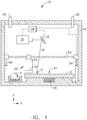
- FIG. 1 illustrates schematically an exemplary additive manufacturing apparatus 10 suitable for carrying out an additive manufacturing process.
- the apparatus 10 may include a build platform 12, an excess powder container 14, a directed energy source 16, a beam steering apparatus 18, and a coater 20, all of which may be enclosed in a housing 22.
- a build platform 12 may include a build platform 12, an excess powder container 14, a directed energy source 16, a beam steering apparatus 18, and a coater 20, all of which may be enclosed in a housing 22.
- X, Y, and Z three mutually perpendicular axes labeled X, Y, and Z as seen in FIGS. 1 and 2 . This coordinate system is used merely for convenience and does not imply that any particular orientation of the apparatus 10 is required for operation.
- the build platform 12 is a rigid structure providing a planar worksurface 24.
- the excess powder container 14 is an open-topped vessel which lies adjacent to the build platform 12, and serves as a repository for excess powder P.
- the directed energy source 16 is a device producing radiant energy with suitable power and other operating characteristics to melt and fuse the powder during the build process, described in more detail below.
- the directed energy source 16 may comprise a laser or an electron beam gun.
- the beam steering apparatus 18 functions so that a beam "B" from the directed energy source 16 can be focused to a desired spot size and steered to a desired position in an X-Y plane coincident with the worksurface 24.
- it may comprise one or more mirrors, prisms, and/or lenses and provided with suitable actuators.
- the housing 22 encloses the working components of the apparatus 10 and may be sealed to prevent contamination.
- the housing 22 may be purged with a gas or gas mixture through inlet and outlet ports 26 and 28, respectively.
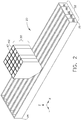
- the coater 20 may include a reservoir assembly 30 positioned above a dispenser 32.
- the dispenser 32 has a width "W" extending between first and second ends 34, 36 respectively.
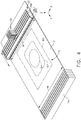
- the width W may be substantially equal to a width W of the build platform 12 in the X direction, as shown in FIG. 4 .
- the dispenser 32 includes one or more elongated troughs (designated 38 generally) extending parallel to the width W.
- the dispenser 32 includes a plurality of troughs 38, specifically five troughs 38A, 38B, 38C, 38D, 38E, in a side-by-side arrangement.
- the term "trough” refers to any structure capable of enclosing powder prior to dispensing it, and does not necessarily imply an open channel structure.
- Each trough 38A-E includes one or more deposition valves 40.
- valve means any structure having a first position or condition which permits flow of powdered material (referred to as an "open” state), and a second position or condition which blocks flow of powdered material (referred to as a "closed” state).
- the action of the deposition valve 40 may be binary (i.e. on-off) or variable (i.e. open to a variable degree).
- suitable devices usable as deposition valves 40 include microelectromechanical system (“MEMS”) devices or piezoelectric devices.
- MEMS microelectromechanical system
- each trough 38A-E includes a linear array of deposition valves 40 extending along the width W of the dispenser 32.
- the size of the deposition valves 40 i.e. their flow area in the open state
- the spacing between individual deposition valves 40, and the total number of deposition valves 40 may be selected in order to provide a desired spatial resolution and total coverage area.
- the amount of powder deposited and resulting powder layer thickness may be controlled by the duration that the deposition valves 40 are open.
- the reservoir assembly 30 includes at least one reservoir 42 disposed over each trough 38A-E.
- Each reservoir 42 is defined by suitable walls or dividers forming a volume effective to store and dispense a powder, referred to generally at "P".
- Each individual reservoir 42 may be loaded with a powder P having unique characteristics, such as composition and/or powder particle size.
- the powder P may be of any suitable material for additive manufacturing.
- the powder P may be a metallic, polymeric, organic, or ceramic powder.
- the reservoir assembly 30 is optional and that powder P may be loaded directly into the troughs 38.
- Each reservoir 42 may incorporate a feed valve 44 operable to selectively permit flow of powder P from the reservoir 42 into the associated trough 38A-E.
- the structure of the feed valve 44 may be as described above for the deposition valves 40.
- the feed valves 44 may be used to selectively flow powder for various purposes, such as for limiting the amount of powder P in the trough 38A-E (to avoid interfering with operation of the deposition valves 40); or for mixing powders from several different reservoirs 42 together in one trough 38A-E.
- a group of reservoirs 42 are arranged in a side-by-side configuration extending parallel to the width W of the dispenser 32.
- this group may be referred to as a "column" 46.
- the reservoirs 42 within the column 46 are grouped above a funnel-shaped collector 48 with a single outlet 50 which discharges into the respective trough 38A-E.
- One such column 46 and collector 48 may be provided for each trough 38A-E.
- each reservoir 42 could be positioned to discharge directly into one of the troughs 38A-E.
- each reservoir 42 It is possible to arbitrarily load each reservoir 42 with a unique powder (e.g. a powder having a unique composition and/or particle size). It is also possible to load a group of reservoirs 42 with powders having at least one common property. For example, the reservoirs 42 of a particular column 46 could be loaded with several powders having the same composition but differing powder particle sizes in each individual reservoir 42.
- a unique powder e.g. a powder having a unique composition and/or particle size
- the coater 20 is mounted for controlled movement relative to the build platform 12 in at least one axis parallel to the worksurface 24, such that powder can be dispensed over a selected area of the build platform 12.
- the width W of the dispenser 32 is substantially equal to a width W of the build platform 12, so no movement is required in the X direction in order to dispense powder in a specified location.
- the coater 20 is mounted to the housing 22 using a first actuator 52 permitting controlled movement in the "length" direction.
- the first actuator 52 is depicted schematically in FIG. 2 , with the understanding that devices such as pneumatic or hydraulic cylinders, ballscrew or linear electric actuators, and so forth, may be used for this purpose.
- the coater 20 may include apparatus for controlled movement relative to the build platform 12 perpendicular to the worksurface 24 (i.e. Z direction) so as to control the distance between the coater 20 and the worksurface 24.
- a second actuator 54 is shown schematically for this purpose. Relative movement in the Z direction could be produced by movement of the coater 20, the build platform 12, or some combination of the two.
- the apparatus may include a vibrator 56 operable to vibrate the build platform 12 and level deposited powder, as described in more detail below.
- a vibrator 56 operable to vibrate the build platform 12 and level deposited powder, as described in more detail below.
- an electromechanical vibrator may be used for this function.
- the functions of the apparatus 10 may be implemented using an electronic controller 58 depicted schematically in FIG 1 .
- one or more processor-based devices such as a microcomputer or programmable logic controller (“PLC”) may be used for this purpose.
- PLC programmable logic controller
- Functional connections of the controller 58 to the other components of the apparatus 10 are shown as single dashed lines.
- the apparatus 10 described above is operable to produce a layered component comprising fused powder, where the coater 20 can be used to deposit powder having specified characteristics at each specified location within a layer.
- FIG. 4 shows the coater 20 disposed above the build platform 12.
- a first column 46 of the reservoirs 42 is provided with a first powder "P1" to be fed to the first trough 38A
- a second column 46 of the reservoirs 42 is provided with a second powder "P2" to be fed to the second trough 38B
- a fifth column 46 of the reservoirs 42 is provided with a third powder "P3" to be fed to the fifth trough 38E.
- the exemplary layer of the exemplary component C has an outer portion 60, an intermediate portion 62, and an inner portion 64, shown by dashed lines.
- the exemplary layer of the exemplary component C has an outer portion 60, an intermediate portion 62, and an inner portion 64, shown by dashed lines.
- the different portions require powders having different characteristics (e.g. chemical composition and/or powder particle size).
- FIG. 5 shows one-half of the layer of the component C which has been subdivided into a grid 10 elements wide by 15 elements tall. The size of the grid elements and their spacing are exaggerated for purposes of clarity in illustration.
- the representation of the component C as a series of layers each with a grid of elements may be modeled, for example, using appropriate solid modeling or computer-aided design software.
- Each unique hatching pattern shown in FIG. 5 represents the characteristics of one unique powder (e.g. composition and/or particle size).
- FIG. 6 shows four exemplary rows located at arbitrary stations along the Y axis, and denoted 1, 2, 3, and 4.
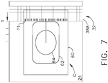
- FIG. 7 illustrates the coater 20 applying the elements of row 1 on the worksurface 24. All 15 elements of row 1 require the first powder "P1". Accordingly, 15 deposition valves 40 of the first trough 38A would be actuated to deposit powder when the first trough 38A is aligned over station 1.
- the first actuator 52 may be used to move the coater 20 to this position prior to deposition of powder. This movement (and all movements of the coater 20) may be discrete or continuous. In the case of discrete movement, the coater 20 would be stepped to the desired position before actuating the deposition valves 40. In the case of continuous movement, the coater 20 would be set in motion and then the deposition valves would be programmed to actuate at specific times during the movement.
- FIG. 8 illustrates the coater 20 applying row 2 on the worksurface.
- the outer six elements of row 2 require the first powder P1 while the inner nine elements require the second powder P2.
- six of the deposition valves 40 of the first trough 38A would deposit powder when the first trough 38A is aligned over station 2 (see upper portion of FIG. 8 ).
- nine of the deposition valves 40 of the second trough 38B would deposit powder when the second trough 38B is aligned over station 2 (see lower portion of FIG. 8 ).
- the two deposition steps complete row 2 as shown in FIG. 6 .
- FIG. 9 illustrates the coater 20 applying row 3 on the worksurface.
- the outer six elements of row 2 require the first powder P1, four intermediate elements require the second powder P2, and the inner five elements require the third powder P3.
- six of the deposition valves 40 of the first trough 38A deposit powder when the first trough 38A is aligned over station 3 (see upper portion of FIG. 9 ).
- four of the deposition valves 40 of the second trough 38B deposit powder when the second trough 38B is aligned over station 3 (see middle portion of FIG. 9 ).
- five of the deposition valves 40 of the fifth trough 38E deposit powder when the fifth trough 38E is aligned over station 3 (see lower portion of FIG. 9 ).
- the three deposition steps complete row 3 as shown in FIG. 6 .
- FIG. 10 illustrates the coater 20 applying row 4 on the worksurface.
- the outer six elements of row 4 require the first powder P1, two intermediate elements require the second powder P2, and the inner seven elements require the third powder P3.
- six of the deposition valves 40 of the first trough 38A deposit powder when the first trough 38A is aligned over station 4 (see upper portion of FIG. 10 ).
- two of the deposition valves 40 of the second trough 38B deposit powder when the second trough 38B is aligned over station 4 (see middle portion of FIG. 10 ).
- seven of the deposition valves 40 of the fifth trough 38E deposit powder when the fifth trough 38E is aligned over station 4 (see upper portion of FIG. 10 ).
- the three deposition steps complete row 4 as shown in FIG. 6 .
- deposition steps described above would be carried out in a row-by-row fashion as required to complete an entire layer of the component C.
- a device such as the vibrator 56 described above may be used to level the powder and provide a more uniform layer after deposition.
- the directed energy source 16 is used to melt the deposited powder, which may correspond to a two-dimensional cross-section of the component C being built.
- the directed energy source 16 emits a beam "B” and the beam steering apparatus 18 is used to steer the focal spot "S" of the beam B over the exposed powder surface in an appropriate pattern.
- the exposed layer of the powder P is heated by the beam B to a temperature allowing it to melt, flow, and consolidate. This step may be described as "fusing" the powder P.
- the coater 20 is moved vertically apart from the build platform 12 by a layer increment, and another layer of powder deposited as described above.
- the directed energy source 16 again emits a beam B and the beam steering apparatus 18 is used to steer the focal spot S of the beam B over the exposed powder surface in an appropriate pattern.
- the exposed layer of the powder P is heated by the beam B to a temperature allowing it to melt, flow, and consolidate both within the top layer and with the lower, previously-solidified layer.
- This cycle of applying powder P and then laser melting the powder P is repeated until the entire component C is complete.
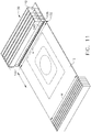
- FIGS. 11-13 illustrate an alternative coater 120 including a reservoir assembly 130 positioned above a dispenser 132.
- the dispenser 132 has a width "W" extending between first and second ends 134, 136 respectively.
- the width W may be substantially equal to a width W of the build platform 12.
- the dispenser 132 includes one or more elongated troughs 138 extending parallel to the width W.
- the dispenser includes a plurality of troughs 138 in a side-by-side arrangement.
- Each trough 138 includes one or more deposition valves 140.
- each trough 138 includes a linear array of deposition valves 140 extending along the width W of the dispenser 132.
- the size of the deposition valves 140 i.e. their flow area in the open state
- the spacing between individual deposition valves 140 and the total number of deposition valves 140 may be selected in order to provide a desired spatial resolution and total coverage area.
- the amount of powder deposited and resulting powder layer thickness may be controlled by the duration that the deposition valves 140 are open.
- the reservoir assembly 130 includes at least one reservoir 142 disposed over each trough.
- Each reservoir 142 is defined by suitable walls or dividers forming a volume effective to store and dispense a powder P. It is noted that the reservoir assembly 130 is optional and that powder P may be loaded directly into the troughs 138.
- each reservoir 142 is elongated and extends parallel to the width W of the dispenser 132.
- the bottom of the each reservoir 142 is shaped into a funnel-shaped collector 148 with a single outlet 150 which discharges into the respective trough 138.
- One such reservoir 14 is provided for each trough 138.
- Each reservoir 142 may incorporate a feed valve 144 operable to selectively permit flow of power from the associated reservoir 142.
- the feed valves 144 may be used to selectively flow powder for various purposes, such as for limiting the amount of powder P in the trough 138 (to avoid interfering with operation of the deposition valves).
- the structure of the feed valve 144 may be as described above for the deposition valves 140.
- the feed valve 144 may incorporate a metering function.
- the feed valve 44 comprises an elongated cylinder 166 with a diameter "D" fitting closely to the interior of the reservoir 42. longitudinal grooves 168 are formed into the outer surface of the cylinder 166 and arrayed around its periphery.
- the cylinder 166 may be rotated at a constant RPM, causing powder P to be metered into the trough 138 at a constant rate.
- the apparatus and method described above provides flexibility in the deposition of powder.
- two or more different powders may be blended to produce a powder with intermediate properties before the powder is deposited.
- two or more different powders may be individually deposited over a common location to result in mixed or graded properties after the powder is fused.
- FIG. 14 illustrates a mechanical joint assembly 200 including a bracket 202 defining a clevis with a pair of spaced-apart ears 204.
- a rod-end bearing 206 is disposed between the ears 204 and mounted for pivoting movement by a shaft 208.
- the joint assembly could be manufactured in a single process by including sacrificial support material in the gaps "G" between the individual components. The support material may then be removed after the build process, leaving a working assembly.
- sacrificial support materials include unfused powder, low-temperature melting materials, or materials readily dissolved by acids or caustics ("leachable materials").
Landscapes
- Engineering & Computer Science (AREA)
- Chemical & Material Sciences (AREA)
- Materials Engineering (AREA)
- Manufacturing & Machinery (AREA)
- Physics & Mathematics (AREA)
- Optics & Photonics (AREA)
- Mechanical Engineering (AREA)
- Plasma & Fusion (AREA)
- Powder Metallurgy (AREA)
- Application Of Or Painting With Fluid Materials (AREA)
- Coating Apparatus (AREA)
Abstract
Description
- The present invention relates generally to additive manufacturing, and more particularly to apparatus and methods for additive manufacturing using a powder coater.
- Additive manufacturing is a process in which material is built up layer-by-layer to form a component. Unlike casting processes, additive manufacturing is limited only by the position resolution of the machine and not limited by requirements for providing draft angles, avoiding overhangs, etc. as required by casting. Additive manufacturing is also referred to by terms such as "layered manufacturing," "reverse machining," "direct metal laser melting" (DMLM), and "3-D printing." Such terms are treated as synonyms for purposes of the present invention.
- A known type of additive manufacturing process involves depositing powdered material onto a worksurface and then fusing the powder using radiant energy. This type of process often requires a large bulk of powder provided as a bed or applied in a continuous large layer. This can waste powder and limit process flexibility.
- Accordingly, there is a need for an additive manufacturing process capable of depositing powder in a flexible pattern and/or depositing multiple powders.
- This need is addressed by an apparatus and method for layered manufacturing of parts incorporating a coater having multiple deposition valves. It may also include reservoirs and be capable of depositing multiple powders.
- The invention may be best understood by reference to the following description taken in conjunction with the accompanying drawing figures in which:
-
FIG. 1 is a schematic cross-section of an exemplary additive manufacturing apparatus; -
FIG. 2 is a schematic perspective view of a coater usable with the apparatus ofFIG. 1 ; -
FIG. 3 is a partially-sectioned view of the coater ofFIG. 2 ; -
FIG. 4 is a perspective view of the coater ofFIG. 2 mounted over a build platform; -
FIG. 5 is a top view of an exemplary part to be constructed; -
FIG. 6 is a top view of the part ofFIG. 5 , showing exemplary rows thereof; -
FIGS. 7-10 are schematic top views showing a sequence of powder deposition in the construction of the component shown inFIG. 5 ; -
FIG. 11 is a schematic perspective view of an alternative coater usable with the apparatus ofFIG. 1 ; -
FIG. 12 is a partially-sectioned view of the coater ofFIG. 11 ; -
FIG. 13 is a view taken along lines 13-13 ofFIG. 12 ; and -
FIG. 14 is an exemplary part constructed using the apparatus described herein. - Referring to the drawings wherein identical reference numerals denote the same
FIG. 1 illustrates schematically an exemplaryadditive manufacturing apparatus 10 suitable for carrying out an additive manufacturing process. Theapparatus 10 may include abuild platform 12, anexcess powder container 14, a directedenergy source 16, abeam steering apparatus 18, and acoater 20, all of which may be enclosed in ahousing 22. Each of these components will be described in more detail below. In describing theapparatus 10, reference may be made to a system of three mutually perpendicular axes labeled X, Y, and Z as seen inFIGS. 1 and2 . This coordinate system is used merely for convenience and does not imply that any particular orientation of theapparatus 10 is required for operation. - The
build platform 12 is a rigid structure providing aplanar worksurface 24. Theexcess powder container 14 is an open-topped vessel which lies adjacent to thebuild platform 12, and serves as a repository for excess powder P. - The directed
energy source 16 is a device producing radiant energy with suitable power and other operating characteristics to melt and fuse the powder during the build process, described in more detail below. For example, the directedenergy source 16 may comprise a laser or an electron beam gun. - The
beam steering apparatus 18 functions so that a beam "B" from the directedenergy source 16 can be focused to a desired spot size and steered to a desired position in an X-Y plane coincident with theworksurface 24. For example, it may comprise one or more mirrors, prisms, and/or lenses and provided with suitable actuators. - The
housing 22 encloses the working components of theapparatus 10 and may be sealed to prevent contamination. Thehousing 22 may be purged with a gas or gas mixture through inlet andoutlet ports - As seen in
FIGS. 2 and3 , thecoater 20 may include areservoir assembly 30 positioned above adispenser 32. - The
dispenser 32 has a width "W" extending between first andsecond ends build platform 12 in the X direction, as shown inFIG. 4 . Thedispenser 32 includes one or more elongated troughs (designated 38 generally) extending parallel to the width W. In the illustrated example, thedispenser 32 includes a plurality of troughs 38, specifically fivetroughs - Each
trough 38A-E includes one ormore deposition valves 40. As used herein the term "valve" means any structure having a first position or condition which permits flow of powdered material (referred to as an "open" state), and a second position or condition which blocks flow of powdered material (referred to as a "closed" state). The action of thedeposition valve 40 may be binary (i.e. on-off) or variable (i.e. open to a variable degree). Nonlimiting examples of suitable devices usable asdeposition valves 40 include microelectromechanical system ("MEMS") devices or piezoelectric devices. In the illustrated example eachtrough 38A-E includes a linear array ofdeposition valves 40 extending along the width W of thedispenser 32. The size of the deposition valves 40 (i.e. their flow area in the open state), the spacing betweenindividual deposition valves 40, and the total number ofdeposition valves 40 may be selected in order to provide a desired spatial resolution and total coverage area. In use, the amount of powder deposited and resulting powder layer thickness may be controlled by the duration that thedeposition valves 40 are open. - The
reservoir assembly 30 includes at least onereservoir 42 disposed over eachtrough 38A-E. Eachreservoir 42 is defined by suitable walls or dividers forming a volume effective to store and dispense a powder, referred to generally at "P". Eachindividual reservoir 42 may be loaded with a powder P having unique characteristics, such as composition and/or powder particle size. It should be appreciated that the powder P may be of any suitable material for additive manufacturing. For example, the powder P may be a metallic, polymeric, organic, or ceramic powder. It is noted that thereservoir assembly 30 is optional and that powder P may be loaded directly into the troughs 38. - Each
reservoir 42 may incorporate afeed valve 44 operable to selectively permit flow of powder P from thereservoir 42 into the associatedtrough 38A-E. The structure of thefeed valve 44 may be as described above for thedeposition valves 40. Thefeed valves 44 may be used to selectively flow powder for various purposes, such as for limiting the amount of powder P in thetrough 38A-E (to avoid interfering with operation of the deposition valves 40); or for mixing powders from severaldifferent reservoirs 42 together in onetrough 38A-E. - In the illustrated example, a group of
reservoirs 42 are arranged in a side-by-side configuration extending parallel to the width W of thedispenser 32. For convenience of description this group may be referred to as a "column" 46. Thereservoirs 42 within thecolumn 46 are grouped above a funnel-shaped collector 48 with asingle outlet 50 which discharges into therespective trough 38A-E. Onesuch column 46 andcollector 48 may be provided for eachtrough 38A-E. Alternatively, eachreservoir 42 could be positioned to discharge directly into one of thetroughs 38A-E. - It is possible to arbitrarily load each
reservoir 42 with a unique powder (e.g. a powder having a unique composition and/or particle size). It is also possible to load a group ofreservoirs 42 with powders having at least one common property. For example, thereservoirs 42 of aparticular column 46 could be loaded with several powders having the same composition but differing powder particle sizes in eachindividual reservoir 42. - The
coater 20 is mounted for controlled movement relative to thebuild platform 12 in at least one axis parallel to theworksurface 24, such that powder can be dispensed over a selected area of thebuild platform 12. In the illustrated example, The width W of thedispenser 32 is substantially equal to a width W of thebuild platform 12, so no movement is required in the X direction in order to dispense powder in a specified location. Thecoater 20 is mounted to thehousing 22 using afirst actuator 52 permitting controlled movement in the "length" direction. Thefirst actuator 52 is depicted schematically inFIG. 2 , with the understanding that devices such as pneumatic or hydraulic cylinders, ballscrew or linear electric actuators, and so forth, may be used for this purpose. - Optionally, the
coater 20 may include apparatus for controlled movement relative to thebuild platform 12 perpendicular to the worksurface 24 (i.e. Z direction) so as to control the distance between thecoater 20 and theworksurface 24. Asecond actuator 54 is shown schematically for this purpose. Relative movement in the Z direction could be produced by movement of thecoater 20, thebuild platform 12, or some combination of the two. - Optionally, the apparatus may include a
vibrator 56 operable to vibrate thebuild platform 12 and level deposited powder, as described in more detail below. For example, an electromechanical vibrator may be used for this function. - The functions of the
apparatus 10 may be implemented using anelectronic controller 58 depicted schematically inFIG 1 . For example, one or more processor-based devices such as a microcomputer or programmable logic controller ("PLC") may be used for this purpose. Functional connections of thecontroller 58 to the other components of theapparatus 10 are shown as single dashed lines. - The
apparatus 10 described above is operable to produce a layered component comprising fused powder, where thecoater 20 can be used to deposit powder having specified characteristics at each specified location within a layer. - An exemplary build process for a component using the apparatus described above will now be described with reference to
FIGS. 4-10 .FIG. 4 shows thecoater 20 disposed above thebuild platform 12. - In this example, a
first column 46 of thereservoirs 42 is provided with a first powder "P1" to be fed to thefirst trough 38A, asecond column 46 of thereservoirs 42 is provided with a second powder "P2" to be fed to thesecond trough 38B, and afifth column 46 of thereservoirs 42 is provided with a third powder "P3" to be fed to thefifth trough 38E. - One layer of a component "C" is depicted as dashed lines. The exemplary layer of the exemplary component C has an
outer portion 60, anintermediate portion 62, and aninner portion 64, shown by dashed lines. For purposes of this example, it is assumed that the different portions require powders having different characteristics (e.g. chemical composition and/or powder particle size). -
FIG. 5 shows one-half of the layer of the component C which has been subdivided into agrid 10 elements wide by 15 elements tall. The size of the grid elements and their spacing are exaggerated for purposes of clarity in illustration. The representation of the component C as a series of layers each with a grid of elements may be modeled, for example, using appropriate solid modeling or computer-aided design software. Each unique hatching pattern shown inFIG. 5 represents the characteristics of one unique powder (e.g. composition and/or particle size).FIG. 6 shows four exemplary rows located at arbitrary stations along the Y axis, and denoted 1, 2, 3, and 4. -
FIG. 7 illustrates thecoater 20 applying the elements ofrow 1 on theworksurface 24. All 15 elements ofrow 1 require the first powder "P1". Accordingly, 15deposition valves 40 of thefirst trough 38A would be actuated to deposit powder when thefirst trough 38A is aligned overstation 1. Thefirst actuator 52 may be used to move thecoater 20 to this position prior to deposition of powder. This movement (and all movements of the coater 20) may be discrete or continuous. In the case of discrete movement, thecoater 20 would be stepped to the desired position before actuating thedeposition valves 40. In the case of continuous movement, thecoater 20 would be set in motion and then the deposition valves would be programmed to actuate at specific times during the movement. -
FIG. 8 illustrates thecoater 20 applyingrow 2 on the worksurface. The outer six elements ofrow 2 require the first powder P1 while the inner nine elements require the second powder P2. Accordingly, six of thedeposition valves 40 of thefirst trough 38A would deposit powder when thefirst trough 38A is aligned over station 2 (see upper portion ofFIG. 8 ). Subsequently, nine of thedeposition valves 40 of thesecond trough 38B would deposit powder when thesecond trough 38B is aligned over station 2 (see lower portion ofFIG. 8 ). The two deposition stepscomplete row 2 as shown inFIG. 6 . -
FIG. 9 illustrates thecoater 20 applyingrow 3 on the worksurface. The outer six elements ofrow 2 require the first powder P1, four intermediate elements require the second powder P2, and the inner five elements require the third powder P3. Accordingly, six of thedeposition valves 40 of thefirst trough 38A deposit powder when thefirst trough 38A is aligned over station 3 (see upper portion ofFIG. 9 ). Subsequently, four of thedeposition valves 40 of thesecond trough 38B deposit powder when thesecond trough 38B is aligned over station 3 (see middle portion ofFIG. 9 ). Finally, five of thedeposition valves 40 of thefifth trough 38E deposit powder when thefifth trough 38E is aligned over station 3 (see lower portion ofFIG. 9 ). The three deposition stepscomplete row 3 as shown inFIG. 6 . -
FIG. 10 illustrates thecoater 20 applyingrow 4 on the worksurface. The outer six elements ofrow 4 require the first powder P1, two intermediate elements require the second powder P2, and the inner seven elements require the third powder P3. Accordingly, six of thedeposition valves 40 of thefirst trough 38A deposit powder when thefirst trough 38A is aligned over station 4 (see upper portion ofFIG. 10 ). Subsequently, two of thedeposition valves 40 of thesecond trough 38B deposit powder when thesecond trough 38B is aligned over station 4 (see middle portion ofFIG. 10 ). Finally, seven of thedeposition valves 40 of thefifth trough 38E deposit powder when thefifth trough 38E is aligned over station 4 (see upper portion ofFIG. 10 ). The three deposition stepscomplete row 4 as shown inFIG. 6 . - The deposition steps described above would be carried out in a row-by-row fashion as required to complete an entire layer of the component C. Optionally, a device such as the
vibrator 56 described above may be used to level the powder and provide a more uniform layer after deposition. - Subsequent to deposition, the directed
energy source 16 is used to melt the deposited powder, which may correspond to a two-dimensional cross-section of the component C being built. The directedenergy source 16 emits a beam "B" and thebeam steering apparatus 18 is used to steer the focal spot "S" of the beam B over the exposed powder surface in an appropriate pattern. The exposed layer of the powder P is heated by the beam B to a temperature allowing it to melt, flow, and consolidate. This step may be described as "fusing" the powder P. - After a layer is fused, the
coater 20 is moved vertically apart from thebuild platform 12 by a layer increment, and another layer of powder deposited as described above. The directedenergy source 16 again emits a beam B and thebeam steering apparatus 18 is used to steer the focal spot S of the beam B over the exposed powder surface in an appropriate pattern. The exposed layer of the powder P is heated by the beam B to a temperature allowing it to melt, flow, and consolidate both within the top layer and with the lower, previously-solidified layer. - Optionally, it may be desired to purge the
troughs 38A-E between cycles of the process, for example where it is desired to deposit different mixtures of powder from previous cycles. This may be accomplished by moving thetrough 38A-E over theexcess powder container 14 and then opening thedeposition valves 40 to dump the excess powder. The process may be augmented by flowing a gas or mixture of gases through thetroughs 38A-E. - This cycle of applying powder P and then laser melting the powder P is repeated until the entire component C is complete.
-
FIGS. 11-13 illustrate analternative coater 120 including areservoir assembly 130 positioned above adispenser 132. - The
dispenser 132 has a width "W" extending between first and second ends 134, 136 respectively. The width W may be substantially equal to a width W of thebuild platform 12. Thedispenser 132 includes one or moreelongated troughs 138 extending parallel to the width W. In the illustrated example, the dispenser includes a plurality oftroughs 138 in a side-by-side arrangement. - Each
trough 138 includes one ormore deposition valves 140. In the illustrated example eachtrough 138 includes a linear array ofdeposition valves 140 extending along the width W of thedispenser 132. The size of the deposition valves 140 (i.e. their flow area in the open state), the spacing betweenindividual deposition valves 140, and the total number ofdeposition valves 140 may be selected in order to provide a desired spatial resolution and total coverage area. In use, the amount of powder deposited and resulting powder layer thickness may be controlled by the duration that thedeposition valves 140 are open. - The
reservoir assembly 130 includes at least onereservoir 142 disposed over each trough. Eachreservoir 142 is defined by suitable walls or dividers forming a volume effective to store and dispense a powder P. It is noted that thereservoir assembly 130 is optional and that powder P may be loaded directly into thetroughs 138. - In the illustrated example (see
FIG. 13 ), eachreservoir 142 is elongated and extends parallel to the width W of thedispenser 132. The bottom of the eachreservoir 142 is shaped into a funnel-shapedcollector 148 with asingle outlet 150 which discharges into therespective trough 138. Onesuch reservoir 14 is provided for eachtrough 138. - Each
reservoir 142 may incorporate afeed valve 144 operable to selectively permit flow of power from the associatedreservoir 142. Thefeed valves 144 may be used to selectively flow powder for various purposes, such as for limiting the amount of powder P in the trough 138 (to avoid interfering with operation of the deposition valves). The structure of thefeed valve 144 may be as described above for thedeposition valves 140. In this specific example thefeed valve 144 may incorporate a metering function. As seen inFIG. 13 , thefeed valve 44 comprises an elongated cylinder 166 with a diameter "D" fitting closely to the interior of thereservoir 42.longitudinal grooves 168 are formed into the outer surface of the cylinder 166 and arrayed around its periphery. The cylinder 166 may be rotated at a constant RPM, causing powder P to be metered into thetrough 138 at a constant rate. - The apparatus and method described above provides flexibility in the deposition of powder. For example, two or more different powders (varying in composition or particle size) may be blended to produce a powder with intermediate properties before the powder is deposited. Alternatively, two or more different powders may be individually deposited over a common location to result in mixed or graded properties after the powder is fused.
- The apparatus and method described above may be used to construct monolithic or unitary components as well as assemblies of multiple components. For example,
FIG. 14 illustrates a mechanicaljoint assembly 200 including abracket 202 defining a clevis with a pair of spaced-apart ears 204. A rod-end bearing 206 is disposed between theears 204 and mounted for pivoting movement by ashaft 208. Using the apparatus and methods described above, the joint assembly could be manufactured in a single process by including sacrificial support material in the gaps "G" between the individual components. The support material may then be removed after the build process, leaving a working assembly. Nonlimiting examples of sacrificial support materials include unfused powder, low-temperature melting materials, or materials readily dissolved by acids or caustics ("leachable materials"). - The foregoing has described apparatus and methods for additive manufacturing. All of the features disclosed in this specification (including any accompanying claims, abstract and drawings), and/or all of the steps of any method or process so disclosed, may be combined in any combination, except combinations where at least some of such features and/or steps are mutually exclusive.
- Each feature disclosed in this specification (including any accompanying claims, abstract and drawings) may be replaced by alternative features serving the same, equivalent or similar purpose, unless expressly stated otherwise. Thus, unless expressly stated otherwise, each feature disclosed is one example only of a generic series of equivalent or similar features.
- The invention is not restricted to the details of the foregoing embodiment(s). The invention extends any novel one, or any novel combination, of the features disclosed in this specification (including any accompanying claims, abstract and drawings), or to any novel one, or any novel combination, of the steps of any method or process so disclosed.
- Various aspects and embodiments of the invention are defined by the following
- 1. A additive manufacturing apparatus, comprising:
a coater comprising:
at least one trough including a plurality of side-by-side deposition valves. - 2. The apparatus of
clause 1 wherein a plurality of the troughs are disposed in a side-by-side configuration. - 3. The apparatus of
clause 1 further comprising at least one reservoir communicating with the at least one trough, wherein the at least one reservoir includes a feed valve operable to selectively block or permit flow of a powder from the reservoir to the trough. - 4. The apparatus of
clause 3 wherein the feed valve is configured to meter powder at a constant flow rate. - 5. The apparatus of
clause 3 wherein a plurality of reservoirs are grouped into a column, each of the reservoirs of the column communicating with a funnel-shaped collector. - 6. The apparatus of
clause 3 wherein a plurality of the columns are grouped together in a side-by-side fashion, the reservoirs of each column communicating with a funnel-shaped collector, wherein each collector communicates with one of the troughs. - 7. The apparatus of
clause 1 wherein the coater is mounted for movement along at least one axis above a build platform defining a worksurface. - 8. The apparatus of clause 7 further comprising an excess powder container disposed adjacent the build platform.
- 9. The apparatus of clause 7 further comprising a directed energy source operable to selectively fuse powder deposited on the worksurface.
- 10. An additive manufacturing method, comprising:
- positioning a coater adjacent a worksurface, the coater comprising a trough including a plurality of side-by-side deposition valves;
- depositing powder from the trough onto the build platform through at least one of the deposition valves; and
- using radiant energy to fuse the powder.
- 11. The method of
clause 10 wherein the step of depositing powder includes:- depositing powder from the through onto the build platform through at least one of the deposition valves while the coater is in a first position;
- moving the coater to a new position; and
- repeating the steps of depositing powder and moving the coater to build up a layer of powder on the build platform.
- 12. The method of
clause 10 further comprising vibrating the deposited powder to level it before fusing. - 13. The method of
clause 10 wherein the coater includes a plurality of troughs in a side-by-side arrangement, each trough including a plurality of side-by-side deposition valves, and the step of depositing powder includes:- moving the coater to position a selected one of the troughs in a first position;
- depositing powder from the selected trough onto the build platform through at least one of the deposition valves thereof; and
- repeating the steps of moving the coater and depositing powder, using two or more of the troughs, such that the deposits of the powders from each of the troughs lie in a single row.
- 14. The method of
clause 13 wherein the step of depositing powder further comprises repeating the steps of moving the coater and depositing powder to build up a layer of powder on the build platform. - 15. The method of
clause 13 wherein the powder deposited by each trough differs from the powder deposited by the other troughs in at least one of its composition or particle size. - 16. The method of
clause 10 wherein the coater comprises a reservoir communicating with the at least one trough, the reservoir including a feed valve operable to selectively block or permit flow of a powder from the reservoir to the trough, the method further comprising using the feed valve to flow a controlled quantity of powder from the reservoir to the trough. - 17. The method of
clause 10 wherein the coater comprises a reservoir communicating with the at least one trough, the reservoir including a feed valve operable to selectively block or permit flow of a powder from the reservoir to the trough, the method further comprising using the feed valve to flow a powder from the reservoir to the trough at a controlled rate. - 18. The method of
clause 10 wherein:- the coater comprises two or more troughs each including a plurality of side-by-side deposition valves;
- the coater comprises two or more reservoirs communicating with each trough, each reservoir including a feed valve operable to selectively block or permit flow of a powder from the reservoir to the corresponding trough; and
- wherein the method further comprises using the feed valves to flow a mixture of powders from the reservoir to the trough, wherein each of the powders of the mixture differs from the other powders of the mixture in at least one of its composition or particle size.
- 19. The method of
clause 18 wherein a plurality of the reservoirs are grouped into a column, each of the reservoirs of the column communicating with a funnel-shaped collector, wherein each collector communicates with one of the troughs.
Claims (15)
- A additive manufacturing apparatus, comprising:
a coater comprising:
at least one trough including a plurality of side-by-side deposition valves. - The apparatus of claim 1 wherein a plurality of the troughs are disposed in a side-by-side configuration.
- The apparatus of claim 2 further comprising a plurality of reservoirs grouped into a column, each of the reservoirs of the column communicating with a funnel-shaped collector.
- The apparatus of claim 3 wherein the plurality of reservoirs include a first reservoir configured to receive a first powder and a second reservoir configured to receive a second powder different than the first powder.
- The apparatus of claim 3 wherein each of the plurality of reservoirs include a feed valve operable to selectively block or permit flow of a powder from the reservoir to the trough, wherein the feed valve is configured to meter powder at a constant flow rate.
- The apparatus of claim 1 wherein the coater is mounted for movement along at least one axis above a build platform defining a worksurface.
- The apparatus of claim 6 further comprising a leveling device configured to level deposited powder on the worksurface of the build platform.
- The apparatus of claim 6 further comprising an excess powder container disposed adjacent the build platform.
- An additive manufacturing method, comprising:positioning a coater adjacent a worksurface, the coater comprising a trough including a plurality of side-by-side deposition valves;depositing powder from the trough onto the build platform through at least one of the deposition valves; andusing radiant energy to fuse the powder.
- The method of claim 9 wherein the coater includes a plurality of troughs in a side-by-side arrangement, each trough including a plurality of side-by-side deposition valves, and the step of depositing powder includes:moving the coater to position a selected one of the troughs in a first position;depositing powder from the selected trough onto the build platform through at least one of the deposition valves thereof; andrepeating the steps of moving the coater and depositing powder, using two or more of the troughs, such that the deposits of the powders from each of the troughs lie in a single row.
- The method of claim 10 further comprising purging the powder from the plurality of troughs.
- The method of claim 11 wherein the step of purging the powder includes:moving the coater to a position adjacent the build platform;opening the deposition valves; anddumping the powder from the plurality of troughs.
- The method of claim 9 further comprising depositing the powder directly into the trough before depositing the powder from the trough onto the build platform through at least one of the deposition valves.
- The method of claim 9 further comprising leveling the deposited powder before fusing.
- The method of claim 9 wherein the step of depositing powder includes:depositing powder from the trough onto the build platform through at least one of the deposition valves while the coater is in a first position;moving the coater to a new position; andrepeating the steps of depositing powder and moving the coater to build up a layer of powder on the build platform.
Applications Claiming Priority (2)
| Application Number | Priority Date | Filing Date | Title |
|---|---|---|---|
| US14/834,517 US10328525B2 (en) | 2015-08-25 | 2015-08-25 | Coater apparatus and method for additive manufacturing |
| EP16185131.6A EP3135407B1 (en) | 2015-08-25 | 2016-08-22 | Coater apparatus and method of additive manufacturing |
Related Parent Applications (2)
| Application Number | Title | Priority Date | Filing Date |
|---|---|---|---|
| EP16185131.6A Division EP3135407B1 (en) | 2015-08-25 | 2016-08-22 | Coater apparatus and method of additive manufacturing |
| EP16185131.6A Division-Into EP3135407B1 (en) | 2015-08-25 | 2016-08-22 | Coater apparatus and method of additive manufacturing |
Publications (1)
| Publication Number | Publication Date |
|---|---|
| EP3632594A1 true EP3632594A1 (en) | 2020-04-08 |
Family
ID=56851402
Family Applications (2)
| Application Number | Title | Priority Date | Filing Date |
|---|---|---|---|
| EP16185131.6A Active EP3135407B1 (en) | 2015-08-25 | 2016-08-22 | Coater apparatus and method of additive manufacturing |
| EP19211745.5A Withdrawn EP3632594A1 (en) | 2015-08-25 | 2016-08-22 | Coater apparatus and method for additive manufacturing |
Family Applications Before (1)
| Application Number | Title | Priority Date | Filing Date |
|---|---|---|---|
| EP16185131.6A Active EP3135407B1 (en) | 2015-08-25 | 2016-08-22 | Coater apparatus and method of additive manufacturing |
Country Status (6)
| Country | Link |
|---|---|
| US (2) | US10328525B2 (en) |
| EP (2) | EP3135407B1 (en) |
| JP (1) | JP6356747B2 (en) |
| CN (2) | CN106475559B (en) |
| BR (1) | BR102016018295A2 (en) |
| CA (1) | CA2939745A1 (en) |
Families Citing this family (28)
| Publication number | Priority date | Publication date | Assignee | Title |
|---|---|---|---|---|
| DE112015003164T5 (en) | 2014-07-09 | 2017-04-20 | Applied Materials, Inc. | LAYERED HEATING, RAW HEATING, PLASMA HEATING AND MULTIPLE APPLICATION MATERIALS FOR ADDITIVE MANUFACTURING |
| CN107771109B (en) | 2015-06-19 | 2021-09-07 | 应用材料公司 | Material distribution and compaction in additive manufacturing |
| DE102015213106A1 (en) | 2015-07-13 | 2017-01-19 | Eos Gmbh Electro Optical Systems | Method and apparatus for building material metering in a generative manufacturing process |
| EP3349968A4 (en) | 2015-09-16 | 2019-08-21 | Applied Materials, Inc. | ADJUSTABLE Z AXIS PRINTING HEAD MODULE FOR ADDITIVE MANUFACTURING SYSTEM |
| EP3349967B1 (en) | 2015-09-16 | 2022-10-26 | Applied Materials, Inc. | Printhead module for additive manufacturing system |
| CN108025499B (en) | 2015-09-16 | 2021-10-08 | 应用材料公司 | Array of printhead modules for additive manufacturing systems |
| US9956612B1 (en) | 2017-01-13 | 2018-05-01 | General Electric Company | Additive manufacturing using a mobile scan area |
| US10022794B1 (en) | 2017-01-13 | 2018-07-17 | General Electric Company | Additive manufacturing using a mobile build volume |
| US20180200962A1 (en) | 2017-01-13 | 2018-07-19 | General Electric Company | Additive manufacturing using a dynamically grown build envelope |
| US10478893B1 (en) * | 2017-01-13 | 2019-11-19 | General Electric Company | Additive manufacturing using a selective recoater |
| US20210206056A1 (en) * | 2017-04-21 | 2021-07-08 | Hewlett-Packard Development Company, L.P. | Additive manufacturing |
| US20180311769A1 (en) * | 2017-04-28 | 2018-11-01 | Divergent Technologies, Inc. | Multi-materials and print parameters for additive manufacturing |
| DE102017213087A1 (en) * | 2017-07-28 | 2019-01-31 | Siemens Aktiengesellschaft | Plant for the powder bed-based additive production of a workpiece with a plurality of metering devices for different types of powder and method for their operation |
| US11273495B2 (en) | 2017-10-02 | 2022-03-15 | General Electric Company | Modified frame and recoating system |
| GB2567877A (en) * | 2017-10-27 | 2019-05-01 | Xaar 3D Ltd | Apparatus and method for the manufacture of three-dimensional objects |
| DE102017221650A1 (en) | 2017-12-01 | 2019-06-06 | Volkswagen Aktiengesellschaft | Method for producing a metal component in powder bed-based 3D metallic printing and apparatus for performing this method |
| CN108044932A (en) * | 2018-01-18 | 2018-05-18 | 南京农业大学 | A kind of device for improving precinct laser sintering/melting process drip molding consistency |
| US11426818B2 (en) | 2018-08-10 | 2022-08-30 | The Research Foundation for the State University | Additive manufacturing processes and additively manufactured products |
| EP3628422B1 (en) * | 2018-09-28 | 2024-11-27 | The Boeing Company | Powder dispensing unit, powder spreading unit, and a vibratory compaction system of an additive manufacturing system and methods therefor |
| GB201819101D0 (en) * | 2018-11-23 | 2019-01-09 | Alchemie Tech Ltd | Powder printhead |
| US11065815B2 (en) * | 2018-12-18 | 2021-07-20 | General Electric Company | Powder dispensing assembly for an additive manufacturing machine |
| US11518097B2 (en) | 2019-11-25 | 2022-12-06 | Applied Materials, Inc. | Selective powder dispenser configurations for additive manufacturing |
| US11524455B2 (en) | 2019-11-25 | 2022-12-13 | Applied Materials, Inc. | Removable unit for selective powder delivery for additive manufacturing |
| US11766832B2 (en) * | 2020-05-13 | 2023-09-26 | The Boeing Company | System and method for additively manufacturing an object |
| US11590705B2 (en) * | 2020-05-13 | 2023-02-28 | The Boeing Company | System and method for additively manufacturing an object |
| CN112264617B (en) * | 2020-08-30 | 2023-03-24 | 湖南华曙高科技股份有限公司 | Powder feeding and spreading device for additive manufacturing equipment and collision powder discharging method thereof |
| CN114714616B (en) * | 2022-03-03 | 2023-11-21 | 上海航天设备制造总厂有限公司 | Powder component controllable powder spreading integrated device and working method |
| CN120055541A (en) * | 2025-03-03 | 2025-05-30 | 华中科技大学 | High-flux additive manufacturing device and method for regulating alloy components by wire precoating solute |
Citations (9)
| Publication number | Priority date | Publication date | Assignee | Title |
|---|---|---|---|---|
| EP0431924A2 (en) * | 1989-12-08 | 1991-06-12 | Massachusetts Institute Of Technology | Three-dimensional printing techniques |
| US20020105114A1 (en) * | 2001-02-07 | 2002-08-08 | Minolta Co., Ltd. | Three-dimensional molding apparatus and three-dimensional molding method |
| US20030074096A1 (en) * | 2001-10-15 | 2003-04-17 | Suman Das | Solid freeform fabrication of structurally engineered multifunctional devices |
| US20030133822A1 (en) * | 2000-06-16 | 2003-07-17 | Urban Harryson | Method and apparatus for producing free-form products |
| US20090169664A1 (en) * | 2005-03-09 | 2009-07-02 | 3D Systems, Inc | Selective Laser Sintering Powder Recycle System |
| US20110233808A1 (en) * | 2006-05-26 | 2011-09-29 | Z Corporation | Apparatus and methods for handling materials in a 3-d printer |
| US20120231175A1 (en) * | 2009-11-26 | 2012-09-13 | Yu En Tan | Process for building three-dimensional objects |
| WO2014083277A1 (en) * | 2012-11-27 | 2014-06-05 | Snecma | A method for the additive manufacturing of a part by selective melting or selective sintering of optimised-compactness powder beds using a high energy beam |
| US20150210010A1 (en) * | 2007-07-25 | 2015-07-30 | Stratasys Ltd. | Solid freeform fabrication using a plurality of modeling materials |
Family Cites Families (43)
| Publication number | Priority date | Publication date | Assignee | Title |
|---|---|---|---|---|
| US5626919A (en) | 1990-03-01 | 1997-05-06 | E. I. Du Pont De Nemours And Company | Solid imaging apparatus and method with coating station |
| US5286573A (en) | 1990-12-03 | 1994-02-15 | Fritz Prinz | Method and support structures for creation of objects by layer deposition |
| US6270335B2 (en) * | 1995-09-27 | 2001-08-07 | 3D Systems, Inc. | Selective deposition modeling method and apparatus for forming three-dimensional objects and supports |
| JP3446577B2 (en) * | 1997-12-22 | 2003-09-16 | 日産自動車株式会社 | Powder supply equipment for laser cladding |
| US6129872A (en) | 1998-08-29 | 2000-10-10 | Jang; Justin | Process and apparatus for creating a colorful three-dimensional object |
| US6811744B2 (en) * | 1999-07-07 | 2004-11-02 | Optomec Design Company | Forming structures from CAD solid models |
| US7045738B1 (en) | 2002-10-01 | 2006-05-16 | Southern Methodist University | Powder delivery system and method |
| AU2003278047A1 (en) | 2002-10-31 | 2004-05-25 | Stephen F. Corbin | System and method for closed-loop control of laser cladding by powder injection |
| WO2004050323A1 (en) * | 2002-12-03 | 2004-06-17 | Objet Geometries Ltd. | Process of and apparatus for three-dimensional printing |
| SE524467C2 (en) | 2002-12-13 | 2004-08-10 | Arcam Ab | Apparatus for manufacturing a three-dimensional product, the apparatus comprising a housing |
| JP2007503342A (en) * | 2003-05-23 | 2007-02-22 | ズィー コーポレイション | Three-dimensional printing apparatus and method |
| WO2005089090A2 (en) * | 2003-10-14 | 2005-09-29 | North Dakota State University | Direct write and freeform fabrication apparatus and method |
| WO2005097476A2 (en) * | 2004-04-02 | 2005-10-20 | Z Corporation | Methods and apparatus for 3d printing |
| ES2760927T3 (en) | 2007-07-13 | 2020-05-18 | Advanced Ceramics Mfg Llc | Aggregate-based chucks for the production of composite material parts and production methods for composite material parts |
| US20090130304A1 (en) | 2007-11-15 | 2009-05-21 | General Electric Company | Methods of forming composite powder coatings and articles thereof |
| JP4798185B2 (en) | 2008-08-05 | 2011-10-19 | パナソニック電工株式会社 | Additive manufacturing equipment |
| US8297478B2 (en) * | 2008-09-30 | 2012-10-30 | Honeywell International Inc. | Powder feed cylinder assemblies and powder feeders |
| GB0821660D0 (en) * | 2008-11-27 | 2008-12-31 | Univ Exeter The | Manufacturing device and method |
| DE102010020416A1 (en) * | 2010-05-12 | 2011-11-17 | Eos Gmbh Electro Optical Systems | Construction space changing device and a device for producing a three-dimensional object with a construction space changing device |
| DE102011075540A1 (en) | 2011-05-10 | 2012-11-15 | Evonik Röhm Gmbh | Multicolored fused deposition modeling printing |
| GB2493398B (en) | 2011-08-05 | 2016-07-27 | Univ Loughborough | Methods and apparatus for selectively combining particulate material |
| US10011089B2 (en) | 2011-12-31 | 2018-07-03 | The Boeing Company | Method of reinforcement for additive manufacturing |
| US9414501B2 (en) | 2012-01-04 | 2016-08-09 | Board Of Regents, The University Of Texas System | Method for connecting inter-layer conductors and components in 3D structures |
| US10518490B2 (en) | 2013-03-14 | 2019-12-31 | Board Of Regents, The University Of Texas System | Methods and systems for embedding filaments in 3D structures, structural components, and structural electronic, electromagnetic and electromechanical components/devices |
| DK2892708T3 (en) * | 2012-09-05 | 2019-01-28 | Aprecia Pharmaceuticals LLC | THREE-DIMENSIONAL PRESSURE SYSTEM AND EQUIPMENT |
| US20140252685A1 (en) | 2013-03-06 | 2014-09-11 | University Of Louisville Research Foundation, Inc. | Powder Bed Fusion Systems, Apparatus, and Processes for Multi-Material Part Production |
| US20140324204A1 (en) | 2013-04-18 | 2014-10-30 | Massachusetts Institute Of Technology | Methods and apparati for implementing programmable pipeline for three-dimensional printing including multi-material applications |
| US9023566B2 (en) | 2013-07-17 | 2015-05-05 | Stratasys, Inc. | ABS part material for electrophotography-based additive manufacturing |
| CN203509029U (en) | 2013-09-18 | 2014-04-02 | 华南理工大学 | Toner feeding brush mechanism of 3D printing machine |
| CN103480844A (en) | 2013-09-18 | 2014-01-01 | 华南理工大学 | 3D (three-dimensional) printer powder pre-production device |
| US20160318104A1 (en) | 2013-12-20 | 2016-11-03 | United Technologies Corporation | Gradient sintered metal preform |
| CN103737932B (en) * | 2014-01-07 | 2016-02-24 | 清华大学 | For powder mixing device and the 3 D-printing system of 3 D-printing system |
| JP5951668B2 (en) * | 2014-03-24 | 2016-07-13 | 株式会社東芝 | Material supply apparatus and additive manufacturing apparatus for additive manufacturing apparatus |
| JP2015182303A (en) | 2014-03-24 | 2015-10-22 | ブラザー工業株式会社 | Three-dimensional shaping device |
| JP5917586B2 (en) | 2014-03-24 | 2016-05-18 | 株式会社東芝 | Material supply apparatus and additive manufacturing apparatus for additive manufacturing apparatus |
| CN103978211B (en) * | 2014-05-23 | 2016-01-20 | 北京理工大学 | The paving powder of dissimilar materials precinct laser fusion and powder recovering device |
| CN106488819B (en) * | 2014-06-20 | 2018-06-22 | 维洛3D公司 | Apparatus, system and method for three-dimensional printing |
| DE112015003164T5 (en) * | 2014-07-09 | 2017-04-20 | Applied Materials, Inc. | LAYERED HEATING, RAW HEATING, PLASMA HEATING AND MULTIPLE APPLICATION MATERIALS FOR ADDITIVE MANUFACTURING |
| CN106687291B (en) * | 2014-09-09 | 2020-10-16 | 极光实验室有限公司 | 3D printing method and device |
| US10286606B2 (en) * | 2014-09-15 | 2019-05-14 | Massachusetts Institute Of Technology | Methods and apparatus for additive manufacturing along user-specified toolpaths |
| EP3253560B1 (en) * | 2015-02-05 | 2019-11-06 | Stratasys Ltd. | Digitally-controlled three-dimensional printing of polymerizable materials |
| KR102307599B1 (en) * | 2015-03-16 | 2021-10-05 | 엘지전자 주식회사 | Printing apparatus for building three-dimensional object |
| JP6644493B2 (en) | 2015-08-18 | 2020-02-12 | ローランドディー.ジー.株式会社 | 3D modeling equipment |
-
2015
- 2015-08-25 US US14/834,517 patent/US10328525B2/en active Active
-
2016
- 2016-08-09 BR BR102016018295A patent/BR102016018295A2/en not_active Application Discontinuation
- 2016-08-16 JP JP2016159463A patent/JP6356747B2/en not_active Expired - Fee Related
- 2016-08-19 CA CA2939745A patent/CA2939745A1/en not_active Abandoned
- 2016-08-22 EP EP16185131.6A patent/EP3135407B1/en active Active
- 2016-08-22 EP EP19211745.5A patent/EP3632594A1/en not_active Withdrawn
- 2016-08-25 CN CN201610720841.9A patent/CN106475559B/en active Active
- 2016-08-25 CN CN201911316973.5A patent/CN111497234A/en active Pending
-
2019
- 2019-06-10 US US16/435,896 patent/US20190291212A1/en not_active Abandoned
Patent Citations (9)
| Publication number | Priority date | Publication date | Assignee | Title |
|---|---|---|---|---|
| EP0431924A2 (en) * | 1989-12-08 | 1991-06-12 | Massachusetts Institute Of Technology | Three-dimensional printing techniques |
| US20030133822A1 (en) * | 2000-06-16 | 2003-07-17 | Urban Harryson | Method and apparatus for producing free-form products |
| US20020105114A1 (en) * | 2001-02-07 | 2002-08-08 | Minolta Co., Ltd. | Three-dimensional molding apparatus and three-dimensional molding method |
| US20030074096A1 (en) * | 2001-10-15 | 2003-04-17 | Suman Das | Solid freeform fabrication of structurally engineered multifunctional devices |
| US20090169664A1 (en) * | 2005-03-09 | 2009-07-02 | 3D Systems, Inc | Selective Laser Sintering Powder Recycle System |
| US20110233808A1 (en) * | 2006-05-26 | 2011-09-29 | Z Corporation | Apparatus and methods for handling materials in a 3-d printer |
| US20150210010A1 (en) * | 2007-07-25 | 2015-07-30 | Stratasys Ltd. | Solid freeform fabrication using a plurality of modeling materials |
| US20120231175A1 (en) * | 2009-11-26 | 2012-09-13 | Yu En Tan | Process for building three-dimensional objects |
| WO2014083277A1 (en) * | 2012-11-27 | 2014-06-05 | Snecma | A method for the additive manufacturing of a part by selective melting or selective sintering of optimised-compactness powder beds using a high energy beam |
Also Published As
| Publication number | Publication date |
|---|---|
| US20190291212A1 (en) | 2019-09-26 |
| CN106475559B (en) | 2020-01-10 |
| EP3135407A1 (en) | 2017-03-01 |
| EP3135407B1 (en) | 2020-01-08 |
| US10328525B2 (en) | 2019-06-25 |
| CN106475559A (en) | 2017-03-08 |
| BR102016018295A2 (en) | 2017-03-01 |
| JP6356747B2 (en) | 2018-07-11 |
| US20170057013A1 (en) | 2017-03-02 |
| CN111497234A (en) | 2020-08-07 |
| JP2017043094A (en) | 2017-03-02 |
| CA2939745A1 (en) | 2017-02-25 |
Similar Documents
| Publication | Publication Date | Title |
|---|---|---|
| EP3135407B1 (en) | Coater apparatus and method of additive manufacturing | |
| US20190321889A1 (en) | Apparatus and Methods for Production Additive Manufacturing | |
| US11707888B2 (en) | Method and apparatus for additive manufacturing with shared components | |
| US10882302B2 (en) | Powder delivery for additive manufacturing | |
| RU2641578C2 (en) | Application head in additive manufacturing | |
| US8996155B2 (en) | Apparatus and methods for digital manufacturing | |
| US11420384B2 (en) | Selective curing additive manufacturing method | |
| EP3281727B1 (en) | Apparatus for producing three-dimensional workpiece comprising a plurality of powder application devices | |
| US20180354035A1 (en) | Hopper for powder bed fusion additive manufacturing | |
| CN108691570B (en) | Component incorporating a 3D identification code | |
| EP3466649B1 (en) | Selective sintering additive manufacturing method | |
| TWI753191B (en) | Apparatuses and methods for producing a high-resolution image | |
| KR20240040073A (en) | Laminated metal casting systems and methods | |
| US20250381599A1 (en) | Additive manufacturing apparatus and additive manufacturing process |
Legal Events
| Date | Code | Title | Description |
|---|---|---|---|
| PUAI | Public reference made under article 153(3) epc to a published international application that has entered the european phase |
Free format text: ORIGINAL CODE: 0009012 |
|
| STAA | Information on the status of an ep patent application or granted ep patent |
Free format text: STATUS: THE APPLICATION HAS BEEN PUBLISHED |
|
| AC | Divisional application: reference to earlier application |
Ref document number: 3135407 Country of ref document: EP Kind code of ref document: P |
|
| AK | Designated contracting states |
Kind code of ref document: A1 Designated state(s): AL AT BE BG CH CY CZ DE DK EE ES FI FR GB GR HR HU IE IS IT LI LT LU LV MC MK MT NL NO PL PT RO RS SE SI SK SM TR |
|
| STAA | Information on the status of an ep patent application or granted ep patent |
Free format text: STATUS: REQUEST FOR EXAMINATION WAS MADE |
|
| 17P | Request for examination filed |
Effective date: 20201008 |
|
| RBV | Designated contracting states (corrected) |
Designated state(s): AL AT BE BG CH CY CZ DE DK EE ES FI FR GB GR HR HU IE IS IT LI LT LU LV MC MK MT NL NO PL PT RO RS SE SI SK SM TR |
|
| STAA | Information on the status of an ep patent application or granted ep patent |
Free format text: STATUS: EXAMINATION IS IN PROGRESS |
|
| 17Q | First examination report despatched |
Effective date: 20210617 |
|
| STAA | Information on the status of an ep patent application or granted ep patent |
Free format text: STATUS: THE APPLICATION IS DEEMED TO BE WITHDRAWN |
|
| 18D | Application deemed to be withdrawn |
Effective date: 20211028 |