EP3632590A1 - Additive manufacturing machine having reconfigurable gas nozzles - Google Patents
Additive manufacturing machine having reconfigurable gas nozzles Download PDFInfo
- Publication number
- EP3632590A1 EP3632590A1 EP19196685.2A EP19196685A EP3632590A1 EP 3632590 A1 EP3632590 A1 EP 3632590A1 EP 19196685 A EP19196685 A EP 19196685A EP 3632590 A1 EP3632590 A1 EP 3632590A1
- Authority
- EP
- European Patent Office
- Prior art keywords
- additive manufacturing
- manufacturing apparatus
- nozzle
- gas
- build
- Prior art date
- Legal status (The legal status is an assumption and is not a legal conclusion. Google has not performed a legal analysis and makes no representation as to the accuracy of the status listed.)
- Granted
Links
Images


Classifications
-
- B—PERFORMING OPERATIONS; TRANSPORTING
- B23—MACHINE TOOLS; METAL-WORKING NOT OTHERWISE PROVIDED FOR
- B23K—SOLDERING OR UNSOLDERING; WELDING; CLADDING OR PLATING BY SOLDERING OR WELDING; CUTTING BY APPLYING HEAT LOCALLY, e.g. FLAME CUTTING; WORKING BY LASER BEAM
- B23K26/00—Working by laser beam, e.g. welding, cutting or boring
- B23K26/34—Laser welding for purposes other than joining
- B23K26/342—Build-up welding
-
- B—PERFORMING OPERATIONS; TRANSPORTING
- B22—CASTING; POWDER METALLURGY
- B22F—WORKING METALLIC POWDER; MANUFACTURE OF ARTICLES FROM METALLIC POWDER; MAKING METALLIC POWDER; APPARATUS OR DEVICES SPECIALLY ADAPTED FOR METALLIC POWDER
- B22F10/00—Additive manufacturing of workpieces or articles from metallic powder
- B22F10/20—Direct sintering or melting
- B22F10/28—Powder bed fusion, e.g. selective laser melting [SLM] or electron beam melting [EBM]
-
- B—PERFORMING OPERATIONS; TRANSPORTING
- B22—CASTING; POWDER METALLURGY
- B22F—WORKING METALLIC POWDER; MANUFACTURE OF ARTICLES FROM METALLIC POWDER; MAKING METALLIC POWDER; APPARATUS OR DEVICES SPECIALLY ADAPTED FOR METALLIC POWDER
- B22F12/00—Apparatus or devices specially adapted for additive manufacturing; Auxiliary means for additive manufacturing; Combinations of additive manufacturing apparatus or devices with other processing apparatus or devices
- B22F12/22—Driving means
-
- B—PERFORMING OPERATIONS; TRANSPORTING
- B22—CASTING; POWDER METALLURGY
- B22F—WORKING METALLIC POWDER; MANUFACTURE OF ARTICLES FROM METALLIC POWDER; MAKING METALLIC POWDER; APPARATUS OR DEVICES SPECIALLY ADAPTED FOR METALLIC POWDER
- B22F12/00—Apparatus or devices specially adapted for additive manufacturing; Auxiliary means for additive manufacturing; Combinations of additive manufacturing apparatus or devices with other processing apparatus or devices
- B22F12/30—Platforms or substrates
- B22F12/33—Platforms or substrates translatory in the deposition plane
-
- B—PERFORMING OPERATIONS; TRANSPORTING
- B22—CASTING; POWDER METALLURGY
- B22F—WORKING METALLIC POWDER; MANUFACTURE OF ARTICLES FROM METALLIC POWDER; MAKING METALLIC POWDER; APPARATUS OR DEVICES SPECIALLY ADAPTED FOR METALLIC POWDER
- B22F12/00—Apparatus or devices specially adapted for additive manufacturing; Auxiliary means for additive manufacturing; Combinations of additive manufacturing apparatus or devices with other processing apparatus or devices
- B22F12/70—Gas flow means
-
- B—PERFORMING OPERATIONS; TRANSPORTING
- B28—WORKING CEMENT, CLAY, OR STONE
- B28B—SHAPING CLAY OR OTHER CERAMIC COMPOSITIONS; SHAPING SLAG; SHAPING MIXTURES CONTAINING CEMENTITIOUS MATERIAL, e.g. PLASTER
- B28B1/00—Producing shaped prefabricated articles from the material
- B28B1/001—Rapid manufacturing of 3D objects by additive depositing, agglomerating or laminating of material
-
- B—PERFORMING OPERATIONS; TRANSPORTING
- B29—WORKING OF PLASTICS; WORKING OF SUBSTANCES IN A PLASTIC STATE IN GENERAL
- B29C—SHAPING OR JOINING OF PLASTICS; SHAPING OF MATERIAL IN A PLASTIC STATE, NOT OTHERWISE PROVIDED FOR; AFTER-TREATMENT OF THE SHAPED PRODUCTS, e.g. REPAIRING
- B29C64/00—Additive manufacturing, i.e. manufacturing of three-dimensional [3D] objects by additive deposition, additive agglomeration or additive layering, e.g. by 3D printing, stereolithography or selective laser sintering
- B29C64/20—Apparatus for additive manufacturing; Details thereof or accessories therefor
- B29C64/245—Platforms or substrates
-
- B—PERFORMING OPERATIONS; TRANSPORTING
- B29—WORKING OF PLASTICS; WORKING OF SUBSTANCES IN A PLASTIC STATE IN GENERAL
- B29C—SHAPING OR JOINING OF PLASTICS; SHAPING OF MATERIAL IN A PLASTIC STATE, NOT OTHERWISE PROVIDED FOR; AFTER-TREATMENT OF THE SHAPED PRODUCTS, e.g. REPAIRING
- B29C64/00—Additive manufacturing, i.e. manufacturing of three-dimensional [3D] objects by additive deposition, additive agglomeration or additive layering, e.g. by 3D printing, stereolithography or selective laser sintering
- B29C64/20—Apparatus for additive manufacturing; Details thereof or accessories therefor
- B29C64/264—Arrangements for irradiation
- B29C64/268—Arrangements for irradiation using laser beams; using electron beams [EB]
-
- B—PERFORMING OPERATIONS; TRANSPORTING
- B29—WORKING OF PLASTICS; WORKING OF SUBSTANCES IN A PLASTIC STATE IN GENERAL
- B29C—SHAPING OR JOINING OF PLASTICS; SHAPING OF MATERIAL IN A PLASTIC STATE, NOT OTHERWISE PROVIDED FOR; AFTER-TREATMENT OF THE SHAPED PRODUCTS, e.g. REPAIRING
- B29C64/00—Additive manufacturing, i.e. manufacturing of three-dimensional [3D] objects by additive deposition, additive agglomeration or additive layering, e.g. by 3D printing, stereolithography or selective laser sintering
- B29C64/30—Auxiliary operations or equipment
- B29C64/364—Conditioning of environment
-
- B—PERFORMING OPERATIONS; TRANSPORTING
- B29—WORKING OF PLASTICS; WORKING OF SUBSTANCES IN A PLASTIC STATE IN GENERAL
- B29C—SHAPING OR JOINING OF PLASTICS; SHAPING OF MATERIAL IN A PLASTIC STATE, NOT OTHERWISE PROVIDED FOR; AFTER-TREATMENT OF THE SHAPED PRODUCTS, e.g. REPAIRING
- B29C64/00—Additive manufacturing, i.e. manufacturing of three-dimensional [3D] objects by additive deposition, additive agglomeration or additive layering, e.g. by 3D printing, stereolithography or selective laser sintering
- B29C64/30—Auxiliary operations or equipment
- B29C64/364—Conditioning of environment
- B29C64/371—Conditioning of environment using an environment other than air, e.g. inert gas
-
- B—PERFORMING OPERATIONS; TRANSPORTING
- B33—ADDITIVE MANUFACTURING TECHNOLOGY
- B33Y—ADDITIVE MANUFACTURING, i.e. MANUFACTURING OF THREE-DIMENSIONAL [3D] OBJECTS BY ADDITIVE DEPOSITION, ADDITIVE AGGLOMERATION OR ADDITIVE LAYERING, e.g. BY 3D PRINTING, STEREOLITHOGRAPHY OR SELECTIVE LASER SINTERING
- B33Y10/00—Processes of additive manufacturing
-
- B—PERFORMING OPERATIONS; TRANSPORTING
- B33—ADDITIVE MANUFACTURING TECHNOLOGY
- B33Y—ADDITIVE MANUFACTURING, i.e. MANUFACTURING OF THREE-DIMENSIONAL [3D] OBJECTS BY ADDITIVE DEPOSITION, ADDITIVE AGGLOMERATION OR ADDITIVE LAYERING, e.g. BY 3D PRINTING, STEREOLITHOGRAPHY OR SELECTIVE LASER SINTERING
- B33Y30/00—Apparatus for additive manufacturing; Details thereof or accessories therefor
-
- B—PERFORMING OPERATIONS; TRANSPORTING
- B33—ADDITIVE MANUFACTURING TECHNOLOGY
- B33Y—ADDITIVE MANUFACTURING, i.e. MANUFACTURING OF THREE-DIMENSIONAL [3D] OBJECTS BY ADDITIVE DEPOSITION, ADDITIVE AGGLOMERATION OR ADDITIVE LAYERING, e.g. BY 3D PRINTING, STEREOLITHOGRAPHY OR SELECTIVE LASER SINTERING
- B33Y40/00—Auxiliary operations or equipment, e.g. for material handling
-
- Y—GENERAL TAGGING OF NEW TECHNOLOGICAL DEVELOPMENTS; GENERAL TAGGING OF CROSS-SECTIONAL TECHNOLOGIES SPANNING OVER SEVERAL SECTIONS OF THE IPC; TECHNICAL SUBJECTS COVERED BY FORMER USPC CROSS-REFERENCE ART COLLECTIONS [XRACs] AND DIGESTS
- Y02—TECHNOLOGIES OR APPLICATIONS FOR MITIGATION OR ADAPTATION AGAINST CLIMATE CHANGE
- Y02P—CLIMATE CHANGE MITIGATION TECHNOLOGIES IN THE PRODUCTION OR PROCESSING OF GOODS
- Y02P10/00—Technologies related to metal processing
- Y02P10/25—Process efficiency
Definitions
- the present disclosure generally relates to an additive manufacturing apparatus. More specifically, the present disclosure relates to nozzles for an additive manufacturing apparatus that can be reconfigured, readily exchanged and moved to improve build performance.
- AM additive manufacturing
- powder bed fusion which is one of the most popular AM technologies, a focused energy beam is used to fuse powder particles together on a layer-wise basis.
- the energy beam may be either an electron beam or laser.
- Laser powder bed fusion processes are referred to in the industry by many different names, the most common of which being selective laser sintering (SLS) and selective laser melting (SLM), depending on the nature of the powder fusion process.
- SLS selective laser sintering
- SLM selective laser melting
- DMLS direct metal laser sintering
- DMLM direct metal laser melting
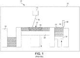
- a laser powder bed fusion system 100 includes a fixed and enclosed build chamber 101. Inside the build chamber 101 is a build plate 102 and an adjacent feed powder reservoir 103 at one end and an excess powder receptacle 104 at the other end. During production, an elevator 105 in the feed powder reservoir 103 lifts a prescribed dose of powder to be spread across the build surface defined by the build plate 102 using a recoater blade 106. Powder overflow is collected in powder receptacle 104, and optionally treated to filter out rough particles before re-use.
- Selected portions 107 of the powder layer are irradiated in each layer using, for example, a laser beam 108.
- the build plate 102 is lowered by a distance equal to one layer thickness in the object 109 being built.
- a subsequent layer of powder is then coated over the last layer and the process repeated until the object 109 is complete.
- the laser beam 108 movement is controlled using galvo scanner 110.
- the laser source (not shown) may be transported from a laser source (not shown) using a fiber optic cable.
- the selective irradiation is conducted in a manner to build object 109 an accordance with computer-aided design (CAD) data.
- CAD computer-aided design
- Powder bed technologies have demonstrated the best resolution capabilities of all known metal additive manufacturing technologies.
- the size of object to be built is limited by the size of the machine's powder bed.
- Increasing the size of the powder bed has limits due to the needed large angle of incidence that can lower scan quality, and weight of the powder bed which can exceed the capabilities of steppers used to lower the build platform.
- a manufacturing apparatus that can handle production of large objects with improved precision and in a manner that is both time and cost-efficient with a minimal waste of raw materials.
- an additive manufacturing apparatus has at least one build unit with a powder delivery mechanism, a powder recoating mechanism and an irradiation beam directing mechanism.
- the additive manufacturing apparatus also includes a rotating build platform, a gas inlet nozzle and a gas exhaust nozzle.
- the gas nozzles direct gas across the build platform or build site or evacuate gas therefrom.
- a positioning mechanism is connected to the gas inlet nozzle and the gas exhaust nozzle, and the positioning mechanism provides independent movement of the gas inlet nozzle and the gas exhaust nozzle.
- an additive manufacturing apparatus in a second aspect, includes at least one build unit having a powder delivery mechanism, a powder recoating mechanism and an irradiation beam directing mechanism.
- the additive manufacturing apparatus also includes a build platform, a gas inlet nozzle and a gas exhaust nozzle, as well as a positioning mechanism connected to the gas inlet nozzle and the gas exhaust nozzle.
- the positioning mechanism is configured to provide independent movement of the gas inlet nozzle and the gas exhaust nozzle.
- the positioning mechanism has a first articulated arm connected to the gas inlet nozzle, and a second articulated arm connected to the gas exhaust nozzle.
- the present invention provides an apparatus and embodiments of the apparatus that can be used to perform powder-based additive layer manufacturing of a large object.
- powder-based additive layer manufacturing include but are not limited to selective laser sintering (SLS), selective laser melting (SLM), direct metal laser sintering (DMLS), direct metal laser melting (DMLM) and electron beam melting (EBM) processes.
- An additive manufacturing apparatus includes a build unit assembly, which is configured to include several components that are essential for additively manufacturing high-precision, large-scale objects. These build components include, for example, a powder recoating mechanism and an irradiation beam directing mechanism.
- the build unit is advantageously attached to a positioning mechanism that allows two- or three-dimensional movement (along x-, y- and z-axes) throughout the build environment, as well as rotation of the build unit in a way that allows leveling of the powder in any direction desired.
- the positioning mechanism may be a gantry, a delta robot, a cable robot, a robotic arm, a belt drive, or the like.
- an additive manufacturing apparatus of the present invention also includes a rotating build platform, or any kind of additive manufacturing machine where the scan head moves relative to the build plate.
- this includes an X, Y, Z gantry system where the processing area moves about the build plate.
- this build platform has a substantially circular configuration but is not so limited. Since the build unit of the apparatus is mobile, this eliminates the need to lower the build platform as successive layers of powder are built up, as it is in conventional powder bed systems. Accordingly, the rotating build platform of the present invention is preferably vertically stationary.
- FIG. 2 depicts a schematic representation of an additive manufacturing apparatus 200 of an embodiment of the present disclosure.
- the apparatus 200 may include a build enclosure 201 housing the entire apparatus 200 and object 230 to be built.
- the apparatus 200 includes a build unit 202 and a rotating build platform 210.
- the apparatus builds an object 230 in a powder bed 214 formed between an outer grown build envelope 224 and, in many cases, an inner build envelope 226.
- the object 230 may be a large annular object, such as, but not limited to, a turbine or vane shrouding, a central engine shaft, a casing, a compressor liner, a combustor liner, a duct, an array of smaller objects arranged onto the large build plate, etc.
- the build unit 202 may be configured to include several components for additively manufacturing a high-precision, large-scale object or multiple smaller objects.
- a mobile build unit 202 includes a powder delivery mechanism, a powder recoating mechanism, a gas-flow mechanism with a gas-flow zone and an irradiation beam directing mechanism.
- the build unit positioning mechanism 225 may be an X-Y-Z gantry that has one or more x-crossbeams 225X (one shown in FIG. 2 ) that independently move the build unit 202 along the x-axis (i.e. left or right), one or more y-crossbeams 225Y (one shown in FIG. 2 ) that respectively move the build unit 202 along the y-axis (i.e. inward or outward). Such two-dimensional movements across the x-y plane are substantially parallel to the build platform 210 or a build area therewithin. Additionally, the build unit positioning mechanism 225 has one or more z-crossbeams 225Z (two shown in FIG.
- the build unit positioning mechanism 225 is further operable to rotate the build unit 202 around the c-axis and also the b-axis.
- the build unit positioning mechanism 225 may also be a robotic arm (not shown) or other suitable mechanism as desired in the specific application.
- the rotating build platform 210 may be a rigid, ring-shaped or annular structure (i.e. with an inner central hole) configured to rotate 360° around the center of rotation W, or the build platform may be a disk without a central hole.
- the rotating build platform 210 may be secured to an end mount of a motor 216 that is operable to selectively rotate the rotating build platform 210 around the center of rotation W such that the build platform 210 moves in a circular path.
- the motor 216 may be further secured to a stationary support structure 228.
- the motor may also be located elsewhere near the apparatus and mechanically connected with the build platform via a belt for translating motion of the motor to the build platform.
- the gas-flow mechanism comprises a nozzle positioning mechanism 240 having articulated arms 245 attached to a gas inlet nozzle 241 and a gas exhaust nozzle 242. Arm sections are joined by joints 246 that permit each arm section to articulate and move in three dimensions.
- the gas inlet nozzle 241 and the gas exhaust nozzle 242 are used to direct a flow of inert gas across (e.g., from left to right in FIG. 2 ) the build area, so that smoke and particulates may be moved away from the laser beam emanating from build unit 202.
- the gas inlet nozzle 241 blows the inert gas across the build area and the gas exhaust nozzle 242 sucks in the smoke and particulates.
- the articulated arms 245 and joints 246 of the nozzle positioning mechanism 240 permits the nozzles 241, 242 to be independently moved into any desired position in the X-Y plane, as well as any desired height along the Z-axis. This is very important as the build progresses because the build platform height is fixed along the Z-axis, and the nozzles 241 and 242 will need to be raised vertically as the build layers accumulate to maintain the desired flow pattern of inert gas along the top build layer of object 230.
- the nozzle positioning mechanism 240 also allows the angular direction of the nozzles 241, 242 in the X-Y plane to be adjusted, as well as permitting the nozzles to be angled up or down with respect to the Z-axis.
- the articulated arms 245 may be connected to and controlled by a computer-controlled system or robotic controller.
- the inert gas conduit (not shown) may also be routed either internally within the arms 245 or attached to the exterior thereof.
- the positioning mechanism 240 may also provide independent yaw, pitch and roll movement of the gas inlet nozzle and the gas exhaust nozzle.
- the yaw axis is the Z-axis, and the nozzles can be oriented in any direction by pivoting or turning on this axis (e.g., nozzle oriented at 270 degrees in an X-Y plane).
- the roll axis is perpendicular to the yaw axis and the nozzle can rotate about this axis (e.g. nozzle oriented at 270 degrees but rotated or turned about this direction circumferentially).
- the pitch axis is perpendicular to both the yaw and roll axes, and the nozzle can rotate about this axis as well.
- Each of the gas inlet nozzle 241 and the gas exhaust nozzle 242 are configured to be readily replaceable and exchangeable as desired for the specific build or object being built. Each nozzle 241, 242 can be easily and quickly removed from the nozzle positioning mechanism 240 and replaced with another nozzle having a different size and/or shape.
- FIGs. 3-8 illustrate various cross-sectional shapes of the gas inlet nozzle 241 and/or the gas exhaust nozzle 242.
- FIG. 3 illustrates a nozzle 341 having a circular cross-sectional shape.
- FIG. 4 illustrates a nozzle 441 having an oval cross-sectional shape.
- FIG. 5 illustrates a nozzle 541 having a rectangular cross-sectional shape, which is also one example of a polygonal shape.
- the nozzle may have any desired polygonal shape as desired in the specific application, including but not limited to T-shapes, triangular shapes or any other polygonal shape.
- FIG. 6 illustrates a nozzle 641 having a rectangular with rounded corners cross-sectional shape.
- FIG. 7 illustrates a nozzle 741 having a trapezoidal cross-sectional shape.
- FIG. 8 illustrates a nozzle 841 having a trapezoidal with rounded corners cross-sectional shape.
- the length, curvature, internal profile or other characteristic of the nozzles may be modified to better perform in specific applications.
- the interior of the nozzle may incorporate interior baffles or channels to maintain a laminar flow of inert gas across the build area.
- the nozzle may also be tapered so that it either converges or diverges along an axial length thereof.
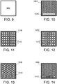
- FIG. 9 illustrates a nozzle 900 having an open interior. This configuration permits gas flow out of (or into) the entire inner area of the nozzle 900.
- FIG. 10 illustrates a nozzle 1000 having a slot 1010 located at the bottom thereof to adjust gas flow characteristics. This may be desired when gas flow needs to be focused along a lower portion of the nozzle area or build area.
- FIG. 11 illustrates a nozzle 1100 having a plurality of rectangular channels 1110 to adjust gas flow characteristics.
- FIG. 12 illustrates a nozzle 1200 having a plurality of circular channels 1210 to adjust gas flow characteristics.
- FIG. 13 illustrates a nozzle 1300 having a plurality of polygonal or hexagonal channels 1310 to adjust gas flow characteristics.
- FIG. 10 illustrates a nozzle 1000 having a slot 1010 located at the bottom thereof to adjust gas flow characteristics. This may be desired when gas flow needs to be focused along a lower portion of the nozzle area or build area.
- FIG. 11 illustrates a nozzle 1100 having a
- FIG. 14 illustrates a nozzle 1400 having a slotted channel 1410 with graduated sized openings along a length thereof to adjust gas flow characteristics.
- the openings are larger towards opposing ends of slot 1410 and progressively become narrower as they approach the center of the slot 1410. This may be desired when gas flow in the center of the nozzle is stronger (i.e., higher velocity) than in side portions of the nozzle, and a laminar velocity gas flow is desired.
- the slot openings may be reversed, with larger slot openings in the center and smaller opening towards the sides. All of the channels illustrated in and described in conjunction with FIGs. 9-14 may be used to straighten gas flow or modify gas flow direction or velocity to optimize gas flow across the build platform or build site.
- suitable powder materials can include metallic alloy, polymer, or ceramic powders.
- Exemplary metallic powder materials are stainless steel alloys, cobalt-chrome, aluminum alloys, titanium alloys, nickel based superalloys, and cobalt based superalloys.
- suitable alloys may include those that have been engineered to have good oxidation resistance, known "superalloys" which have acceptable strength at the elevated temperatures of operation in a gas turbine engine, e.g.
- Hastelloy, Inconel alloys e.g., IN 738, IN 792, IN 939
- Rene alloys e.g., Rene N4, Rene N5, Rene 80, Rene 142, Rene 195
- Haynes alloys Mar M, CM 247, CM 247 LC, C263, 718, X-750, ECY 768, 282, X45, PWA 1483 and CMSX (e.g. CMSX-4) single crystal alloys.
- the manufactured objects of the present invention may be formed with one or more selected crystalline microstructures, such as directionally solidified (“DS") or single-crystal ("SX").
- DS directionally solidified
- SX single-crystal
Landscapes
- Engineering & Computer Science (AREA)
- Chemical & Material Sciences (AREA)
- Materials Engineering (AREA)
- Manufacturing & Machinery (AREA)
- Physics & Mathematics (AREA)
- Mechanical Engineering (AREA)
- Optics & Photonics (AREA)
- Toxicology (AREA)
- Health & Medical Sciences (AREA)
- Plasma & Fusion (AREA)
- Environmental & Geological Engineering (AREA)
- Ceramic Engineering (AREA)
- Powder Metallurgy (AREA)
Abstract
Description
- The present disclosure generally relates to an additive manufacturing apparatus. More specifically, the present disclosure relates to nozzles for an additive manufacturing apparatus that can be reconfigured, readily exchanged and moved to improve build performance.
- Additive manufacturing (AM) encompasses a variety of technologies for producing components in an additive, layer-wise fashion. In powder bed fusion which is one of the most popular AM technologies, a focused energy beam is used to fuse powder particles together on a layer-wise basis. The energy beam may be either an electron beam or laser. Laser powder bed fusion processes are referred to in the industry by many different names, the most common of which being selective laser sintering (SLS) and selective laser melting (SLM), depending on the nature of the powder fusion process. When the powder to be fused is metal, the terms direct metal laser sintering (DMLS) and direct metal laser melting (DMLM) are commonly used.
- Referring to
FIG. 1 , a laser powderbed fusion system 100 includes a fixed and enclosedbuild chamber 101. Inside thebuild chamber 101 is abuild plate 102 and an adjacentfeed powder reservoir 103 at one end and anexcess powder receptacle 104 at the other end. During production, anelevator 105 in thefeed powder reservoir 103 lifts a prescribed dose of powder to be spread across the build surface defined by thebuild plate 102 using arecoater blade 106. Powder overflow is collected inpowder receptacle 104, and optionally treated to filter out rough particles before re-use. - Selected
portions 107 of the powder layer are irradiated in each layer using, for example, alaser beam 108. After irradiation, thebuild plate 102 is lowered by a distance equal to one layer thickness in theobject 109 being built. A subsequent layer of powder is then coated over the last layer and the process repeated until theobject 109 is complete. Thelaser beam 108 movement is controlled usinggalvo scanner 110. The laser source (not shown) may be transported from a laser source (not shown) using a fiber optic cable. The selective irradiation is conducted in a manner to buildobject 109 an accordance with computer-aided design (CAD) data. - Powder bed technologies have demonstrated the best resolution capabilities of all known metal additive manufacturing technologies. However, since the build needs to take place in the powder bed, the size of object to be built is limited by the size of the machine's powder bed. Increasing the size of the powder bed has limits due to the needed large angle of incidence that can lower scan quality, and weight of the powder bed which can exceed the capabilities of steppers used to lower the build platform. In view of the foregoing, there remains a need for a manufacturing apparatus that can handle production of large objects with improved precision and in a manner that is both time and cost-efficient with a minimal waste of raw materials.
- In a first aspect, an additive manufacturing apparatus has at least one build unit with a powder delivery mechanism, a powder recoating mechanism and an irradiation beam directing mechanism. The additive manufacturing apparatus also includes a rotating build platform, a gas inlet nozzle and a gas exhaust nozzle. The gas nozzles direct gas across the build platform or build site or evacuate gas therefrom. A positioning mechanism is connected to the gas inlet nozzle and the gas exhaust nozzle, and the positioning mechanism provides independent movement of the gas inlet nozzle and the gas exhaust nozzle.
- In a second aspect, an additive manufacturing apparatus includes at least one build unit having a powder delivery mechanism, a powder recoating mechanism and an irradiation beam directing mechanism. The additive manufacturing apparatus also includes a build platform, a gas inlet nozzle and a gas exhaust nozzle, as well as a positioning mechanism connected to the gas inlet nozzle and the gas exhaust nozzle. The positioning mechanism is configured to provide independent movement of the gas inlet nozzle and the gas exhaust nozzle. The positioning mechanism has a first articulated arm connected to the gas inlet nozzle, and a second articulated arm connected to the gas exhaust nozzle.
-
-
FIG. 1 illustrates an exemplary prior art powder bed based system for additive manufacturing. -
FIG. 2 illustrates a schematic diagram showing a front view, cross section of an additive manufacturing apparatus, according an aspect of the present disclosure. -
FIG. 3 illustrates a nozzle having a circular cross-sectional shape, according an aspect of the present disclosure. -
FIG. 4 illustrates a nozzle having an oval cross-sectional shape, according an aspect of the present disclosure. -
FIG. 5 illustrates a nozzle having a rectangular cross-sectional shape, according an aspect of the present disclosure. -
FIG. 6 illustrates a nozzle having a rectangular with rounded corners cross-sectional shape, according an aspect of the present disclosure. -
FIG. 7 illustrates a nozzle having a trapezoidal cross-sectional shape, according an aspect of the present disclosure. -
FIG. 8 illustrates a nozzle having a trapezoidal with rounded corners cross-sectional shape, according an aspect of the present disclosure. -
FIG. 9 illustrates a nozzle having an open interior, according an aspect of the present disclosure. -
FIG. 10 illustrates a nozzle having a slot located at the bottom thereof to adjust gas flow characteristics, according an aspect of the present disclosure. -
FIG. 11 illustrates a nozzle having a plurality of rectangular channels to adjust gas flow characteristics, according an aspect of the present disclosure. -
FIG. 12 illustrates a nozzle having a plurality of circular channels to adjust gas flow characteristics, according an aspect of the present disclosure. -
FIG. 13 illustrates a nozzle having a plurality of polygonal or hexagonal channels to adjust gas flow characteristics, according an aspect of the present disclosure. -
FIG. 14 illustrates a nozzle having a slotted channel with graduated sized opening along a length thereof to adjust gas flow characteristics, according an aspect of the present disclosure. - The detailed description set forth below in connection with the appended drawings is intended as a description of various configurations and is not intended to represent the only configurations in which the concepts described herein may be practiced. The detailed description includes specific details for the purpose of providing a thorough understanding of various concepts. However, it will be apparent to those skilled in the art that these concepts may be practiced without these specific details.
- The present invention provides an apparatus and embodiments of the apparatus that can be used to perform powder-based additive layer manufacturing of a large object. Examples of powder-based additive layer manufacturing include but are not limited to selective laser sintering (SLS), selective laser melting (SLM), direct metal laser sintering (DMLS), direct metal laser melting (DMLM) and electron beam melting (EBM) processes.
- An additive manufacturing apparatus provided herein includes a build unit assembly, which is configured to include several components that are essential for additively manufacturing high-precision, large-scale objects. These build components include, for example, a powder recoating mechanism and an irradiation beam directing mechanism. The build unit is advantageously attached to a positioning mechanism that allows two- or three-dimensional movement (along x-, y- and z-axes) throughout the build environment, as well as rotation of the build unit in a way that allows leveling of the powder in any direction desired. The positioning mechanism may be a gantry, a delta robot, a cable robot, a robotic arm, a belt drive, or the like.
- Aside from the build unit, an additive manufacturing apparatus of the present invention also includes a rotating build platform, or any kind of additive manufacturing machine where the scan head moves relative to the build plate. For example, this includes an X, Y, Z gantry system where the processing area moves about the build plate. Preferably, this build platform has a substantially circular configuration but is not so limited. Since the build unit of the apparatus is mobile, this eliminates the need to lower the build platform as successive layers of powder are built up, as it is in conventional powder bed systems. Accordingly, the rotating build platform of the present invention is preferably vertically stationary.
-
FIG. 2 depicts a schematic representation of anadditive manufacturing apparatus 200 of an embodiment of the present disclosure. Theapparatus 200 may include abuild enclosure 201 housing theentire apparatus 200 andobject 230 to be built. Theapparatus 200 includes abuild unit 202 and arotating build platform 210. During operation, the apparatus builds anobject 230 in apowder bed 214 formed between an outergrown build envelope 224 and, in many cases, aninner build envelope 226. Theobject 230 may be a large annular object, such as, but not limited to, a turbine or vane shrouding, a central engine shaft, a casing, a compressor liner, a combustor liner, a duct, an array of smaller objects arranged onto the large build plate, etc. - The
build unit 202 may be configured to include several components for additively manufacturing a high-precision, large-scale object or multiple smaller objects. Amobile build unit 202 includes a powder delivery mechanism, a powder recoating mechanism, a gas-flow mechanism with a gas-flow zone and an irradiation beam directing mechanism. - The build
unit positioning mechanism 225 may be an X-Y-Z gantry that has one or more x-crossbeams 225X (one shown inFIG. 2 ) that independently move thebuild unit 202 along the x-axis (i.e. left or right), one or more y-crossbeams 225Y (one shown inFIG. 2 ) that respectively move thebuild unit 202 along the y-axis (i.e. inward or outward). Such two-dimensional movements across the x-y plane are substantially parallel to thebuild platform 210 or a build area therewithin. Additionally, the buildunit positioning mechanism 225 has one or more z-crossbeams 225Z (two shown inFIG. 2 ) that moves thebuild unit 202 along the z-axis (i.e. upward and downward or substantially perpendicular to thebuild platform 210 or a build area therewithin). The buildunit positioning mechanism 225 is further operable to rotate thebuild unit 202 around the c-axis and also the b-axis. The buildunit positioning mechanism 225 may also be a robotic arm (not shown) or other suitable mechanism as desired in the specific application. - The
rotating build platform 210 may be a rigid, ring-shaped or annular structure (i.e. with an inner central hole) configured to rotate 360° around the center of rotation W, or the build platform may be a disk without a central hole. Therotating build platform 210 may be secured to an end mount of amotor 216 that is operable to selectively rotate therotating build platform 210 around the center of rotation W such that thebuild platform 210 moves in a circular path. Themotor 216 may be further secured to astationary support structure 228. The motor may also be located elsewhere near the apparatus and mechanically connected with the build platform via a belt for translating motion of the motor to the build platform. - The gas-flow mechanism comprises a
nozzle positioning mechanism 240 having articulatedarms 245 attached to agas inlet nozzle 241 and agas exhaust nozzle 242. Arm sections are joined byjoints 246 that permit each arm section to articulate and move in three dimensions. Thegas inlet nozzle 241 and thegas exhaust nozzle 242 are used to direct a flow of inert gas across (e.g., from left to right inFIG. 2 ) the build area, so that smoke and particulates may be moved away from the laser beam emanating frombuild unit 202. Thegas inlet nozzle 241 blows the inert gas across the build area and thegas exhaust nozzle 242 sucks in the smoke and particulates. The articulatedarms 245 andjoints 246 of thenozzle positioning mechanism 240 permits thenozzles nozzles object 230. Thenozzle positioning mechanism 240 also allows the angular direction of thenozzles additive manufacturing apparatus 200 to direct the flow of inert gas exactly where it can provide the most benefit to improve build quality. The articulatedarms 245 may be connected to and controlled by a computer-controlled system or robotic controller. The inert gas conduit (not shown) may also be routed either internally within thearms 245 or attached to the exterior thereof. Thepositioning mechanism 240 may also provide independent yaw, pitch and roll movement of the gas inlet nozzle and the gas exhaust nozzle. The yaw axis is the Z-axis, and the nozzles can be oriented in any direction by pivoting or turning on this axis (e.g., nozzle oriented at 270 degrees in an X-Y plane). The roll axis is perpendicular to the yaw axis and the nozzle can rotate about this axis (e.g. nozzle oriented at 270 degrees but rotated or turned about this direction circumferentially). The pitch axis is perpendicular to both the yaw and roll axes, and the nozzle can rotate about this axis as well. - Each of the
gas inlet nozzle 241 and thegas exhaust nozzle 242 are configured to be readily replaceable and exchangeable as desired for the specific build or object being built. Eachnozzle nozzle positioning mechanism 240 and replaced with another nozzle having a different size and/or shape.FIGs. 3-8 illustrate various cross-sectional shapes of thegas inlet nozzle 241 and/or thegas exhaust nozzle 242.FIG. 3 illustrates anozzle 341 having a circular cross-sectional shape.FIG. 4 illustrates anozzle 441 having an oval cross-sectional shape.FIG. 5 illustrates anozzle 541 having a rectangular cross-sectional shape, which is also one example of a polygonal shape. It is to be understood that the nozzle may have any desired polygonal shape as desired in the specific application, including but not limited to T-shapes, triangular shapes or any other polygonal shape.FIG. 6 illustrates anozzle 641 having a rectangular with rounded corners cross-sectional shape.FIG. 7 illustrates anozzle 741 having a trapezoidal cross-sectional shape.FIG. 8 illustrates anozzle 841 having a trapezoidal with rounded corners cross-sectional shape. In addition to the cross-sectional shape, the length, curvature, internal profile or other characteristic of the nozzles may be modified to better perform in specific applications. For example, the interior of the nozzle may incorporate interior baffles or channels to maintain a laminar flow of inert gas across the build area. The nozzle may also be tapered so that it either converges or diverges along an axial length thereof. -
FIG. 9 illustrates anozzle 900 having an open interior. This configuration permits gas flow out of (or into) the entire inner area of thenozzle 900.FIG. 10 illustrates anozzle 1000 having aslot 1010 located at the bottom thereof to adjust gas flow characteristics. This may be desired when gas flow needs to be focused along a lower portion of the nozzle area or build area.FIG. 11 illustrates anozzle 1100 having a plurality ofrectangular channels 1110 to adjust gas flow characteristics.FIG. 12 illustrates anozzle 1200 having a plurality ofcircular channels 1210 to adjust gas flow characteristics.FIG. 13 illustrates anozzle 1300 having a plurality of polygonal orhexagonal channels 1310 to adjust gas flow characteristics.FIG. 14 illustrates anozzle 1400 having a slottedchannel 1410 with graduated sized openings along a length thereof to adjust gas flow characteristics. The openings are larger towards opposing ends ofslot 1410 and progressively become narrower as they approach the center of theslot 1410. This may be desired when gas flow in the center of the nozzle is stronger (i.e., higher velocity) than in side portions of the nozzle, and a laminar velocity gas flow is desired. Alternatively, the slot openings may be reversed, with larger slot openings in the center and smaller opening towards the sides. All of the channels illustrated in and described in conjunction withFIGs. 9-14 may be used to straighten gas flow or modify gas flow direction or velocity to optimize gas flow across the build platform or build site. - Representative examples of suitable powder materials can include metallic alloy, polymer, or ceramic powders. Exemplary metallic powder materials are stainless steel alloys, cobalt-chrome, aluminum alloys, titanium alloys, nickel based superalloys, and cobalt based superalloys. In addition, suitable alloys may include those that have been engineered to have good oxidation resistance, known "superalloys" which have acceptable strength at the elevated temperatures of operation in a gas turbine engine, e.g. Hastelloy, Inconel alloys (e.g., IN 738, IN 792, IN 939), Rene alloys (e.g., Rene N4, Rene N5, Rene 80, Rene 142, Rene 195), Haynes alloys, Mar M, CM 247, CM 247 LC, C263, 718, X-750, ECY 768, 282, X45, PWA 1483 and CMSX (e.g. CMSX-4) single crystal alloys. The manufactured objects of the present invention may be formed with one or more selected crystalline microstructures, such as directionally solidified ("DS") or single-crystal ("SX").
- This written description uses examples to disclose the invention, including the preferred embodiments, and also to enable any person skilled in the art to practice the invention, including making and using any devices or systems and performing any incorporated methods. The patentable scope of the invention is defined by the claims, and may include other examples that occur to those skilled in the art. Such other examples are intended to be within the scope of the claims if they have structural elements that do not differ from the literal language of the claims, or if they include equivalent structural elements with insubstantial differences from the literal language of the claims. Aspects from the various embodiments described, as well as other known equivalents for each such aspect, can be mixed and matched by one of ordinary skill in the art to construct additional embodiments and techniques in accordance with principles of this application.
Claims (20)
- An additive manufacturing apparatus, comprising:at least one build unit comprising a powder delivery mechanism, a powder recoating mechanism and an irradiation beam directing mechanism;a rotating build platform;a gas inlet nozzle and a gas exhaust nozzle; anda positioning mechanism connected to the gas inlet nozzle and the gas exhaust nozzle, the positioning mechanism configured to provide independent movement of the gas inlet nozzle and the gas exhaust nozzle.
- The additive manufacturing apparatus of claim 1, wherein the positioning mechanism is comprised of a first articulated arm connected to the gas inlet nozzle, and a second articulated arm connected to the gas exhaust nozzle.
- The additive manufacturing apparatus of claim 1, wherein the gas inlet nozzle has an exit shape chosen from one of:
circular, oval, rectangular, rectangular with rounded corners, trapezoidal, trapezoidal with rounded corners, or polygonal. - The additive manufacturing apparatus of claim 1, wherein the gas exhaust nozzle has an entrance shape chosen from one of:
circular, oval, rectangular, rectangular with rounded corners, trapezoidal, trapezoidal with rounded corners, or polygonal. - The additive manufacturing apparatus of claim 1, wherein the gas inlet nozzle and the gas exhaust nozzle are configured to be readily replaceable so nozzles of different shapes can be used in the additive manufacturing apparatus.
- The additive manufacturing apparatus of claim 1, wherein the positioning mechanism is further configured to provide independent movement of the gas inlet nozzle and the gas exhaust nozzle in at least two dimensions that are substantially parallel to the rotating build platform and a third dimension that is substantially perpendicular to the rotating build platform.
- The additive manufacturing apparatus of claim 1, wherein the positioning mechanism is further configured to provide independent yaw, pitch and roll movement of the gas inlet nozzle and the gas exhaust nozzle.
- The additive manufacturing apparatus of claim 1, wherein the rotating build platform is vertically stationary.
- The additive manufacturing apparatus of claim 1, wherein the at least one build unit further comprises a gas-flow mechanism including the gas inlet nozzle and the gas exhaust nozzle, and the gas-flow mechanism provides a substantially laminar gas flow to at least one build area of the build platform.
- The additive manufacturing apparatus of claim 1, wherein the irradiation beam directing mechanism further comprises a laser source or an electron source.
- The additive manufacturing apparatus of claim 10, wherein the irradiation beam directing mechanism emits and directs a laser beam or electron beam at an angle that is substantially perpendicular to a build area of the build platform.
- An additive manufacturing apparatus, comprising:at least one build unit comprising a powder delivery mechanism, a powder recoating mechanism and an irradiation beam directing mechanism;a build platform;a gas inlet nozzle and a gas exhaust nozzle; anda positioning mechanism connected to the gas inlet nozzle and the gas exhaust nozzle, the positioning mechanism configured to provide independent movement of the gas inlet nozzle and the gas exhaust nozzle; andwherein the positioning mechanism is comprised of a first articulated arm connected to the gas inlet nozzle, and a second articulated arm connected to the gas exhaust nozzle.
- The additive manufacturing apparatus of claim 12, wherein the gas inlet nozzle has an exit shape chosen from one of:
circular, oval, rectangular, rectangular with rounded corners, trapezoidal, trapezoidal with rounded corners, or polygonal. - The additive manufacturing apparatus of claim 13, wherein the gas exhaust nozzle has an entrance shape chosen from one of:
circular, oval, rectangular, rectangular with rounded corners, trapezoidal, trapezoidal with rounded corners, or polygonal. - The additive manufacturing apparatus of claim 12, wherein the gas inlet nozzle and the gas exhaust nozzle are configured to be readily replaceable so nozzles of different shapes can be used in the additive manufacturing apparatus.
- The additive manufacturing apparatus of claim 12, wherein the positioning mechanism is further configured to provide independent movement of the gas inlet nozzle and the gas exhaust nozzle in at least two dimensions that are substantially parallel to the build platform and a third dimension that is substantially perpendicular to the build platform.
- The additive manufacturing apparatus of claim 12, wherein the positioning mechanism is further configured to provide independent yaw, pitch and roll movement of the gas inlet nozzle and the gas exhaust nozzle.
- The additive manufacturing apparatus of claim 12, wherein the at least one build unit further comprises a gas-flow mechanism including the gas inlet nozzle and the gas exhaust nozzle, and the gas-flow mechanism provides a substantially laminar gas flow to at least one build area of the build platform.
- The additive manufacturing apparatus of claim 12, wherein the irradiation beam directing mechanism further comprises a laser source or an electron source.
- The additive manufacturing apparatus of claim 19, wherein the irradiation beam directing mechanism emits and directs a laser beam or an electron beam at an angle that is substantially perpendicular to a build area of the build platform.
Applications Claiming Priority (1)
| Application Number | Priority Date | Filing Date | Title |
|---|---|---|---|
| US16/152,555 US20200108559A1 (en) | 2018-10-05 | 2018-10-05 | Additive manufacturing machine having reconfigurable gas nozzles |
Publications (2)
| Publication Number | Publication Date |
|---|---|
| EP3632590A1 true EP3632590A1 (en) | 2020-04-08 |
| EP3632590B1 EP3632590B1 (en) | 2024-06-12 |
Family
ID=67928699
Family Applications (1)
| Application Number | Title | Priority Date | Filing Date |
|---|---|---|---|
| EP19196685.2A Active EP3632590B1 (en) | 2018-10-05 | 2019-09-11 | Additive manufacturing machine having reconfigurable gas nozzles |
Country Status (2)
| Country | Link |
|---|---|
| US (1) | US20200108559A1 (en) |
| EP (1) | EP3632590B1 (en) |
Families Citing this family (6)
| Publication number | Priority date | Publication date | Assignee | Title |
|---|---|---|---|---|
| US11654608B2 (en) * | 2019-05-31 | 2023-05-23 | Berry Global, Inc. | Brim-forming machine and method of use |
| DE102020129419A1 (en) * | 2020-11-09 | 2022-05-12 | Trumpf Laser- Und Systemtechnik Gmbh | Process and device for the production of three-dimensional objects by selective hardening of a building material applied in layers |
| US20220143695A1 (en) * | 2020-11-10 | 2022-05-12 | Palo Alto Research Center Incorporated | Pattern-wise deposition of anti-sintering agents via surface energy modulation for 3d printing |
| CN116917129A (en) * | 2021-03-09 | 2023-10-20 | 戴弗根特技术有限公司 | Rotary additive manufacturing systems and methods |
| US12083597B2 (en) * | 2022-11-01 | 2024-09-10 | Ge Infrastructure Technology Llc | Direct metal laser printing gas manifold |
| US20250073779A1 (en) * | 2023-09-06 | 2025-03-06 | GM Global Technology Operations LLC | System for additive manufacturing having a movable outlet |
Citations (3)
| Publication number | Priority date | Publication date | Assignee | Title |
|---|---|---|---|---|
| WO2014199150A1 (en) * | 2013-06-11 | 2014-12-18 | Renishaw Plc | Additive manufacturing apparatus and method |
| DE102013215377A1 (en) * | 2013-08-05 | 2015-02-05 | Bayerische Motoren Werke Aktiengesellschaft | Gas guiding device, device for producing a component by application of powder layers and method for supplying and extracting gas in such a device |
| US20180200963A1 (en) * | 2017-01-18 | 2018-07-19 | General Electric Company | Systems and methods for additive manufacturing rotating build platforms |
-
2018
- 2018-10-05 US US16/152,555 patent/US20200108559A1/en not_active Abandoned
-
2019
- 2019-09-11 EP EP19196685.2A patent/EP3632590B1/en active Active
Patent Citations (3)
| Publication number | Priority date | Publication date | Assignee | Title |
|---|---|---|---|---|
| WO2014199150A1 (en) * | 2013-06-11 | 2014-12-18 | Renishaw Plc | Additive manufacturing apparatus and method |
| DE102013215377A1 (en) * | 2013-08-05 | 2015-02-05 | Bayerische Motoren Werke Aktiengesellschaft | Gas guiding device, device for producing a component by application of powder layers and method for supplying and extracting gas in such a device |
| US20180200963A1 (en) * | 2017-01-18 | 2018-07-19 | General Electric Company | Systems and methods for additive manufacturing rotating build platforms |
Also Published As
| Publication number | Publication date |
|---|---|
| US20200108559A1 (en) | 2020-04-09 |
| EP3632590B1 (en) | 2024-06-12 |
Similar Documents
| Publication | Publication Date | Title |
|---|---|---|
| EP3632590B1 (en) | Additive manufacturing machine having reconfigurable gas nozzles | |
| EP3453474B1 (en) | Apparatus and method for additive manufacturing with real-time and in-situ adjustment of growth parameters | |
| US20180345600A1 (en) | Method for real-time simultaneous additive and subtractive manufacturing with a dynamically grown build wall | |
| US20180345371A1 (en) | Apparatus and method for angular and rotational additive manufacturing | |
| US11253922B2 (en) | Method for real-time simultaneous and calibrated additive and subtractive manufacturing | |
| CN114653970B (en) | Large-scale material adding machine | |
| JP7268816B2 (en) | Airflow control for additive manufacturing | |
| CN110337359B (en) | Additive manufacturing using a mobile build space | |
| US20210023621A1 (en) | Apparatus and method for continuous additive manufacturing | |
| US20180345378A1 (en) | Apparatus and method for real-time simultaneous additive and subtractive manufacturing with mechanism to recover unused raw material | |
| US20180345379A1 (en) | Apparatus and method for real-time simultaneous additive and subtractive manufacturing | |
| CN110191792A (en) | Use the increasing material manufacturing of mobile scanning area | |
| US12472556B2 (en) | Apparatus and method for angular and rotational additive manufacturing | |
| US11986884B2 (en) | Apparatus and method for additive manufacturing | |
| US20240316649A1 (en) | Additive manufacturing apparatus and fluid flow mechanism |
Legal Events
| Date | Code | Title | Description |
|---|---|---|---|
| PUAI | Public reference made under article 153(3) epc to a published international application that has entered the european phase |
Free format text: ORIGINAL CODE: 0009012 |
|
| STAA | Information on the status of an ep patent application or granted ep patent |
Free format text: STATUS: REQUEST FOR EXAMINATION WAS MADE |
|
| 17P | Request for examination filed |
Effective date: 20190911 |
|
| AK | Designated contracting states |
Kind code of ref document: A1 Designated state(s): AL AT BE BG CH CY CZ DE DK EE ES FI FR GB GR HR HU IE IS IT LI LT LU LV MC MK MT NL NO PL PT RO RS SE SI SK SM TR |
|
| AX | Request for extension of the european patent |
Extension state: BA ME |
|
| RBV | Designated contracting states (corrected) |
Designated state(s): AL AT BE BG CH CY CZ DE DK EE ES FI FR GB GR HR HU IE IS IT LI LT LU LV MC MK MT NL NO PL PT RO RS SE SI SK SM TR |
|
| STAA | Information on the status of an ep patent application or granted ep patent |
Free format text: STATUS: EXAMINATION IS IN PROGRESS |
|
| 17Q | First examination report despatched |
Effective date: 20210208 |
|
| REG | Reference to a national code |
Ref country code: DE Ref legal event code: R079 Free format text: PREVIOUS MAIN CLASS: B22F0003105000 Ipc: B29C0064364000 Ref country code: DE Ref legal event code: R079 Ref document number: 602019053479 Country of ref document: DE Free format text: PREVIOUS MAIN CLASS: B22F0003105000 Ipc: B29C0064364000 |
|
| GRAP | Despatch of communication of intention to grant a patent |
Free format text: ORIGINAL CODE: EPIDOSNIGR1 |
|
| STAA | Information on the status of an ep patent application or granted ep patent |
Free format text: STATUS: GRANT OF PATENT IS INTENDED |
|
| RIC1 | Information provided on ipc code assigned before grant |
Ipc: B33Y 40/00 20200101ALI20240108BHEP Ipc: B33Y 30/00 20150101ALI20240108BHEP Ipc: B33Y 10/00 20150101ALI20240108BHEP Ipc: B22F 12/70 20210101ALI20240108BHEP Ipc: B22F 12/33 20210101ALI20240108BHEP Ipc: B22F 12/00 20210101ALI20240108BHEP Ipc: B22F 10/28 20210101ALI20240108BHEP Ipc: B29C 64/364 20170101AFI20240108BHEP |
|
| INTG | Intention to grant announced |
Effective date: 20240123 |
|
| GRAS | Grant fee paid |
Free format text: ORIGINAL CODE: EPIDOSNIGR3 |
|
| GRAA | (expected) grant |
Free format text: ORIGINAL CODE: 0009210 |
|
| STAA | Information on the status of an ep patent application or granted ep patent |
Free format text: STATUS: THE PATENT HAS BEEN GRANTED |
|
| AK | Designated contracting states |
Kind code of ref document: B1 Designated state(s): AL AT BE BG CH CY CZ DE DK EE ES FI FR GB GR HR HU IE IS IT LI LT LU LV MC MK MT NL NO PL PT RO RS SE SI SK SM TR |
|
| P01 | Opt-out of the competence of the unified patent court (upc) registered |
Effective date: 20240507 |
|
| REG | Reference to a national code |
Ref country code: GB Ref legal event code: FG4D |
|
| REG | Reference to a national code |
Ref country code: CH Ref legal event code: EP |
|
| REG | Reference to a national code |
Ref country code: IE Ref legal event code: FG4D |
|
| REG | Reference to a national code |
Ref country code: DE Ref legal event code: R096 Ref document number: 602019053479 Country of ref document: DE |
|
| PG25 | Lapsed in a contracting state [announced via postgrant information from national office to epo] |
Ref country code: BG Free format text: LAPSE BECAUSE OF FAILURE TO SUBMIT A TRANSLATION OF THE DESCRIPTION OR TO PAY THE FEE WITHIN THE PRESCRIBED TIME-LIMIT Effective date: 20240612 |
|
| PG25 | Lapsed in a contracting state [announced via postgrant information from national office to epo] |
Ref country code: FI Free format text: LAPSE BECAUSE OF FAILURE TO SUBMIT A TRANSLATION OF THE DESCRIPTION OR TO PAY THE FEE WITHIN THE PRESCRIBED TIME-LIMIT Effective date: 20240612 Ref country code: HR Free format text: LAPSE BECAUSE OF FAILURE TO SUBMIT A TRANSLATION OF THE DESCRIPTION OR TO PAY THE FEE WITHIN THE PRESCRIBED TIME-LIMIT Effective date: 20240612 |
|
| REG | Reference to a national code |
Ref country code: LT Ref legal event code: MG9D |
|
| PG25 | Lapsed in a contracting state [announced via postgrant information from national office to epo] |
Ref country code: GR Free format text: LAPSE BECAUSE OF FAILURE TO SUBMIT A TRANSLATION OF THE DESCRIPTION OR TO PAY THE FEE WITHIN THE PRESCRIBED TIME-LIMIT Effective date: 20240913 |
|
| REG | Reference to a national code |
Ref country code: NL Ref legal event code: MP Effective date: 20240612 |
|
| PG25 | Lapsed in a contracting state [announced via postgrant information from national office to epo] |
Ref country code: ES Free format text: LAPSE BECAUSE OF FAILURE TO SUBMIT A TRANSLATION OF THE DESCRIPTION OR TO PAY THE FEE WITHIN THE PRESCRIBED TIME-LIMIT Effective date: 20240612 |
|
| PG25 | Lapsed in a contracting state [announced via postgrant information from national office to epo] |
Ref country code: LV Free format text: LAPSE BECAUSE OF FAILURE TO SUBMIT A TRANSLATION OF THE DESCRIPTION OR TO PAY THE FEE WITHIN THE PRESCRIBED TIME-LIMIT Effective date: 20240612 |
|
| PG25 | Lapsed in a contracting state [announced via postgrant information from national office to epo] |
Ref country code: NO Free format text: LAPSE BECAUSE OF FAILURE TO SUBMIT A TRANSLATION OF THE DESCRIPTION OR TO PAY THE FEE WITHIN THE PRESCRIBED TIME-LIMIT Effective date: 20240912 Ref country code: LV Free format text: LAPSE BECAUSE OF FAILURE TO SUBMIT A TRANSLATION OF THE DESCRIPTION OR TO PAY THE FEE WITHIN THE PRESCRIBED TIME-LIMIT Effective date: 20240612 Ref country code: HR Free format text: LAPSE BECAUSE OF FAILURE TO SUBMIT A TRANSLATION OF THE DESCRIPTION OR TO PAY THE FEE WITHIN THE PRESCRIBED TIME-LIMIT Effective date: 20240612 Ref country code: GR Free format text: LAPSE BECAUSE OF FAILURE TO SUBMIT A TRANSLATION OF THE DESCRIPTION OR TO PAY THE FEE WITHIN THE PRESCRIBED TIME-LIMIT Effective date: 20240913 Ref country code: FI Free format text: LAPSE BECAUSE OF FAILURE TO SUBMIT A TRANSLATION OF THE DESCRIPTION OR TO PAY THE FEE WITHIN THE PRESCRIBED TIME-LIMIT Effective date: 20240612 Ref country code: ES Free format text: LAPSE BECAUSE OF FAILURE TO SUBMIT A TRANSLATION OF THE DESCRIPTION OR TO PAY THE FEE WITHIN THE PRESCRIBED TIME-LIMIT Effective date: 20240612 Ref country code: BG Free format text: LAPSE BECAUSE OF FAILURE TO SUBMIT A TRANSLATION OF THE DESCRIPTION OR TO PAY THE FEE WITHIN THE PRESCRIBED TIME-LIMIT Effective date: 20240612 Ref country code: RS Free format text: LAPSE BECAUSE OF FAILURE TO SUBMIT A TRANSLATION OF THE DESCRIPTION OR TO PAY THE FEE WITHIN THE PRESCRIBED TIME-LIMIT Effective date: 20240912 |
|
| PG25 | Lapsed in a contracting state [announced via postgrant information from national office to epo] |
Ref country code: NL Free format text: LAPSE BECAUSE OF FAILURE TO SUBMIT A TRANSLATION OF THE DESCRIPTION OR TO PAY THE FEE WITHIN THE PRESCRIBED TIME-LIMIT Effective date: 20240612 |
|
| REG | Reference to a national code |
Ref country code: AT Ref legal event code: MK05 Ref document number: 1693879 Country of ref document: AT Kind code of ref document: T Effective date: 20240612 |
|
| PG25 | Lapsed in a contracting state [announced via postgrant information from national office to epo] |
Ref country code: NL Free format text: LAPSE BECAUSE OF FAILURE TO SUBMIT A TRANSLATION OF THE DESCRIPTION OR TO PAY THE FEE WITHIN THE PRESCRIBED TIME-LIMIT Effective date: 20240612 |
|
| PG25 | Lapsed in a contracting state [announced via postgrant information from national office to epo] |
Ref country code: PT Free format text: LAPSE BECAUSE OF FAILURE TO SUBMIT A TRANSLATION OF THE DESCRIPTION OR TO PAY THE FEE WITHIN THE PRESCRIBED TIME-LIMIT Effective date: 20241014 |
|
| PG25 | Lapsed in a contracting state [announced via postgrant information from national office to epo] |
Ref country code: PT Free format text: LAPSE BECAUSE OF FAILURE TO SUBMIT A TRANSLATION OF THE DESCRIPTION OR TO PAY THE FEE WITHIN THE PRESCRIBED TIME-LIMIT Effective date: 20241014 |
|
| PG25 | Lapsed in a contracting state [announced via postgrant information from national office to epo] |
Ref country code: PL Free format text: LAPSE BECAUSE OF FAILURE TO SUBMIT A TRANSLATION OF THE DESCRIPTION OR TO PAY THE FEE WITHIN THE PRESCRIBED TIME-LIMIT Effective date: 20240612 |
|
| PG25 | Lapsed in a contracting state [announced via postgrant information from national office to epo] |
Ref country code: EE Free format text: LAPSE BECAUSE OF FAILURE TO SUBMIT A TRANSLATION OF THE DESCRIPTION OR TO PAY THE FEE WITHIN THE PRESCRIBED TIME-LIMIT Effective date: 20240612 |
|
| PG25 | Lapsed in a contracting state [announced via postgrant information from national office to epo] |
Ref country code: IS Free format text: LAPSE BECAUSE OF FAILURE TO SUBMIT A TRANSLATION OF THE DESCRIPTION OR TO PAY THE FEE WITHIN THE PRESCRIBED TIME-LIMIT Effective date: 20241012 Ref country code: AT Free format text: LAPSE BECAUSE OF FAILURE TO SUBMIT A TRANSLATION OF THE DESCRIPTION OR TO PAY THE FEE WITHIN THE PRESCRIBED TIME-LIMIT Effective date: 20240612 |
|
| PG25 | Lapsed in a contracting state [announced via postgrant information from national office to epo] |
Ref country code: CZ Free format text: LAPSE BECAUSE OF FAILURE TO SUBMIT A TRANSLATION OF THE DESCRIPTION OR TO PAY THE FEE WITHIN THE PRESCRIBED TIME-LIMIT Effective date: 20240612 |
|
| PG25 | Lapsed in a contracting state [announced via postgrant information from national office to epo] |
Ref country code: RO Free format text: LAPSE BECAUSE OF FAILURE TO SUBMIT A TRANSLATION OF THE DESCRIPTION OR TO PAY THE FEE WITHIN THE PRESCRIBED TIME-LIMIT Effective date: 20240612 Ref country code: SK Free format text: LAPSE BECAUSE OF FAILURE TO SUBMIT A TRANSLATION OF THE DESCRIPTION OR TO PAY THE FEE WITHIN THE PRESCRIBED TIME-LIMIT Effective date: 20240612 |
|
| PG25 | Lapsed in a contracting state [announced via postgrant information from national office to epo] |
Ref country code: SM Free format text: LAPSE BECAUSE OF FAILURE TO SUBMIT A TRANSLATION OF THE DESCRIPTION OR TO PAY THE FEE WITHIN THE PRESCRIBED TIME-LIMIT Effective date: 20240612 |
|
| PG25 | Lapsed in a contracting state [announced via postgrant information from national office to epo] |
Ref country code: RO Free format text: LAPSE BECAUSE OF FAILURE TO SUBMIT A TRANSLATION OF THE DESCRIPTION OR TO PAY THE FEE WITHIN THE PRESCRIBED TIME-LIMIT Effective date: 20240612 Ref country code: PL Free format text: LAPSE BECAUSE OF FAILURE TO SUBMIT A TRANSLATION OF THE DESCRIPTION OR TO PAY THE FEE WITHIN THE PRESCRIBED TIME-LIMIT Effective date: 20240612 Ref country code: IS Free format text: LAPSE BECAUSE OF FAILURE TO SUBMIT A TRANSLATION OF THE DESCRIPTION OR TO PAY THE FEE WITHIN THE PRESCRIBED TIME-LIMIT Effective date: 20241012 Ref country code: EE Free format text: LAPSE BECAUSE OF FAILURE TO SUBMIT A TRANSLATION OF THE DESCRIPTION OR TO PAY THE FEE WITHIN THE PRESCRIBED TIME-LIMIT Effective date: 20240612 Ref country code: CZ Free format text: LAPSE BECAUSE OF FAILURE TO SUBMIT A TRANSLATION OF THE DESCRIPTION OR TO PAY THE FEE WITHIN THE PRESCRIBED TIME-LIMIT Effective date: 20240612 Ref country code: AT Free format text: LAPSE BECAUSE OF FAILURE TO SUBMIT A TRANSLATION OF THE DESCRIPTION OR TO PAY THE FEE WITHIN THE PRESCRIBED TIME-LIMIT Effective date: 20240612 Ref country code: SM Free format text: LAPSE BECAUSE OF FAILURE TO SUBMIT A TRANSLATION OF THE DESCRIPTION OR TO PAY THE FEE WITHIN THE PRESCRIBED TIME-LIMIT Effective date: 20240612 Ref country code: SK Free format text: LAPSE BECAUSE OF FAILURE TO SUBMIT A TRANSLATION OF THE DESCRIPTION OR TO PAY THE FEE WITHIN THE PRESCRIBED TIME-LIMIT Effective date: 20240612 |
|
| PG25 | Lapsed in a contracting state [announced via postgrant information from national office to epo] |
Ref country code: IT Free format text: LAPSE BECAUSE OF FAILURE TO SUBMIT A TRANSLATION OF THE DESCRIPTION OR TO PAY THE FEE WITHIN THE PRESCRIBED TIME-LIMIT Effective date: 20240612 |
|
| REG | Reference to a national code |
Ref country code: DE Ref legal event code: R097 Ref document number: 602019053479 Country of ref document: DE |
|
| PG25 | Lapsed in a contracting state [announced via postgrant information from national office to epo] |
Ref country code: DK Free format text: LAPSE BECAUSE OF FAILURE TO SUBMIT A TRANSLATION OF THE DESCRIPTION OR TO PAY THE FEE WITHIN THE PRESCRIBED TIME-LIMIT Effective date: 20240612 |
|
| PLBE | No opposition filed within time limit |
Free format text: ORIGINAL CODE: 0009261 |
|
| STAA | Information on the status of an ep patent application or granted ep patent |
Free format text: STATUS: NO OPPOSITION FILED WITHIN TIME LIMIT |
|
| PG25 | Lapsed in a contracting state [announced via postgrant information from national office to epo] |
Ref country code: MC Free format text: LAPSE BECAUSE OF FAILURE TO SUBMIT A TRANSLATION OF THE DESCRIPTION OR TO PAY THE FEE WITHIN THE PRESCRIBED TIME-LIMIT Effective date: 20240612 |
|
| REG | Reference to a national code |
Ref country code: CH Ref legal event code: PL |
|
| PG25 | Lapsed in a contracting state [announced via postgrant information from national office to epo] |
Ref country code: LU Free format text: LAPSE BECAUSE OF NON-PAYMENT OF DUE FEES Effective date: 20240911 |
|
| 26N | No opposition filed |
Effective date: 20250313 |
|
| GBPC | Gb: european patent ceased through non-payment of renewal fee |
Effective date: 20240912 |
|
| PG25 | Lapsed in a contracting state [announced via postgrant information from national office to epo] |
Ref country code: GB Free format text: LAPSE BECAUSE OF NON-PAYMENT OF DUE FEES Effective date: 20240912 |
|
| REG | Reference to a national code |
Ref country code: BE Ref legal event code: MM Effective date: 20240930 |
|
| PG25 | Lapsed in a contracting state [announced via postgrant information from national office to epo] |
Ref country code: BE Free format text: LAPSE BECAUSE OF NON-PAYMENT OF DUE FEES Effective date: 20240930 |
|
| PG25 | Lapsed in a contracting state [announced via postgrant information from national office to epo] |
Ref country code: FR Free format text: LAPSE BECAUSE OF NON-PAYMENT OF DUE FEES Effective date: 20240930 |
|
| PG25 | Lapsed in a contracting state [announced via postgrant information from national office to epo] |
Ref country code: CH Free format text: LAPSE BECAUSE OF NON-PAYMENT OF DUE FEES Effective date: 20240930 |
|
| PG25 | Lapsed in a contracting state [announced via postgrant information from national office to epo] |
Ref country code: IE Free format text: LAPSE BECAUSE OF NON-PAYMENT OF DUE FEES Effective date: 20240911 |
|
| PG25 | Lapsed in a contracting state [announced via postgrant information from national office to epo] |
Ref country code: SE Free format text: LAPSE BECAUSE OF FAILURE TO SUBMIT A TRANSLATION OF THE DESCRIPTION OR TO PAY THE FEE WITHIN THE PRESCRIBED TIME-LIMIT Effective date: 20240612 |
|
| PGFP | Annual fee paid to national office [announced via postgrant information from national office to epo] |
Ref country code: DE Payment date: 20250820 Year of fee payment: 7 |
|
| PG25 | Lapsed in a contracting state [announced via postgrant information from national office to epo] |
Ref country code: CY Free format text: LAPSE BECAUSE OF FAILURE TO SUBMIT A TRANSLATION OF THE DESCRIPTION OR TO PAY THE FEE WITHIN THE PRESCRIBED TIME-LIMIT; INVALID AB INITIO Effective date: 20190911 |
|
| PG25 | Lapsed in a contracting state [announced via postgrant information from national office to epo] |
Ref country code: HU Free format text: LAPSE BECAUSE OF FAILURE TO SUBMIT A TRANSLATION OF THE DESCRIPTION OR TO PAY THE FEE WITHIN THE PRESCRIBED TIME-LIMIT; INVALID AB INITIO Effective date: 20190911 |