EP3632361B1 - Medical manipulator and surgical system including the same - Google Patents
Medical manipulator and surgical system including the same Download PDFInfo
- Publication number
- EP3632361B1 EP3632361B1 EP19201543.6A EP19201543A EP3632361B1 EP 3632361 B1 EP3632361 B1 EP 3632361B1 EP 19201543 A EP19201543 A EP 19201543A EP 3632361 B1 EP3632361 B1 EP 3632361B1
- Authority
- EP
- European Patent Office
- Prior art keywords
- arm
- manipulator
- base
- end portion
- medical
- Prior art date
- Legal status (The legal status is an assumption and is not a legal conclusion. Google has not performed a legal analysis and makes no representation as to the accuracy of the status listed.)
- Active
Links
Images



Classifications
-
- A—HUMAN NECESSITIES
- A61—MEDICAL OR VETERINARY SCIENCE; HYGIENE
- A61B—DIAGNOSIS; SURGERY; IDENTIFICATION
- A61B1/00—Instruments for performing medical examinations of the interior of cavities or tubes of the body by visual or photographical inspection, e.g. endoscopes; Illuminating arrangements therefor
- A61B1/00147—Holding or positioning arrangements
- A61B1/00149—Holding or positioning arrangements using articulated arms
-
- A—HUMAN NECESSITIES
- A61—MEDICAL OR VETERINARY SCIENCE; HYGIENE
- A61B—DIAGNOSIS; SURGERY; IDENTIFICATION
- A61B34/00—Computer-aided surgery; Manipulators or robots specially adapted for use in surgery
- A61B34/25—User interfaces for surgical systems
-
- A—HUMAN NECESSITIES
- A61—MEDICAL OR VETERINARY SCIENCE; HYGIENE
- A61B—DIAGNOSIS; SURGERY; IDENTIFICATION
- A61B34/00—Computer-aided surgery; Manipulators or robots specially adapted for use in surgery
- A61B34/30—Surgical robots
-
- A—HUMAN NECESSITIES
- A61—MEDICAL OR VETERINARY SCIENCE; HYGIENE
- A61B—DIAGNOSIS; SURGERY; IDENTIFICATION
- A61B34/00—Computer-aided surgery; Manipulators or robots specially adapted for use in surgery
- A61B34/30—Surgical robots
- A61B34/35—Surgical robots for telesurgery
-
- A—HUMAN NECESSITIES
- A61—MEDICAL OR VETERINARY SCIENCE; HYGIENE
- A61B—DIAGNOSIS; SURGERY; IDENTIFICATION
- A61B34/00—Computer-aided surgery; Manipulators or robots specially adapted for use in surgery
- A61B34/30—Surgical robots
- A61B34/37—Leader-follower robots
-
- B—PERFORMING OPERATIONS; TRANSPORTING
- B25—HAND TOOLS; PORTABLE POWER-DRIVEN TOOLS; MANIPULATORS
- B25J—MANIPULATORS; CHAMBERS PROVIDED WITH MANIPULATION DEVICES
- B25J9/00—Program-controlled manipulators
- B25J9/16—Program controls
- B25J9/1679—Program controls characterised by the tasks executed
- B25J9/1689—Teleoperation
-
- A—HUMAN NECESSITIES
- A61—MEDICAL OR VETERINARY SCIENCE; HYGIENE
- A61B—DIAGNOSIS; SURGERY; IDENTIFICATION
- A61B34/00—Computer-aided surgery; Manipulators or robots specially adapted for use in surgery
- A61B34/30—Surgical robots
- A61B2034/301—Surgical robots for introducing or steering flexible instruments inserted into the body, e.g. catheters or endoscopes
-
- A—HUMAN NECESSITIES
- A61—MEDICAL OR VETERINARY SCIENCE; HYGIENE
- A61B—DIAGNOSIS; SURGERY; IDENTIFICATION
- A61B34/00—Computer-aided surgery; Manipulators or robots specially adapted for use in surgery
- A61B34/70—Manipulators specially adapted for use in surgery
- A61B34/74—Manipulators with manual electric input means
Definitions
- the disclosure relates to a medical manipulator and a surgical system including the medical manipulator.
- base end portions (support portions) of the manipulator arms are fixed to a platform.
- two manipulator arms are attached to an arm base, and the arm base is configured to be moved on a rail.
- Document 4 discloses an apparatus including a base, a member having first and second ends, and a curved support configured to support a robotic arm, and a method involving adjusting a member to position a curved support configured to support a robotic arm, positioning the robotic arm at a location on the curved support, and adjusting the robotic arm in accordance with a non-surgical adjustment such that the robotic instrument is within range of a target area.
- Document 5 discloses a medical robot system having a surgery robot, a movable bed and a diagnostic imaging apparatus.
- the surgery robot has a plurality of arms having front ends equipped with manipulators and endoscopes, respectively.
- the movable bed is put on a station, and configured so that the position, direction and posture can be changed on the station.
- a system control unit controls the operations of the surgery robot, the movable bed and the diagnostic imaging apparatus.
- Document 6 discloses a medical manipulator including a holding portion whose proximal end portion is fixed to a base; a positioning portion that has a fixing portion that is fixed to a distal end portion of the holding portion, and that is formed such that a treatment portion of a surgical instrument is able to move relative to the fixing portion; a reference orientation detecting portion that detects an orientation of a reference position on the positioning portion; a drive section that is used to move the treatment portion relative to the fixing portion; and a displacement detecting section that detects an amount of movement, including angular displacement, of the treatment portion relative to the reference position, and that calculates as the orientation on the treatment portion an orientation that is different by an amount of angular displacement that it has itself detected from the orientation on the reference position detected by the reference orientation detecting portion.
- Document 7 discloses a bed mount surgical robot, for performing a surgical procedure on a patient lying on an operating bed using a surgical instrument mounted on an end portion of a robot arm, including: a main unit joined to the operating bed, a support arm rotatably joined to the main unit, and one or more robot arms rotatably joined to the support arm. Multiple robot arms may be joined to a support arm, which itself may be joined to a main unit mounted on the operating bed. Also, the robot arms may be mounted onto the bed.
- Document 8 discloses telerobotic, telesurgical, and/or surgical robotic devices, systems, and methods employing surgical robotic linkages that may have more degrees of freedom than an associated surgical end effector n space.
- a processor can calculate a tool motion that includes pivoting of the tool about an aperture site.
- Linkages movable along a range of configurations for a given end effector position may be driven toward configurations which inhibit collisions.
- An object of an aspect of one or more embodiments may be to provide a medical manipulator that can increase the degrees of freedom of manipulator arms with multi-degree of freedom arranged for a patient and can avoid interference between the manipulator arms with multi-degree of freedom, and a surgical system including the medical manipulator.
- a medical manipulator of a first aspect includes: a first manipulator arm with multi-degree of freedom that holds a medical tool at a distal end portion thereof; a second manipulator arm with multi-degree of freedom that holds a medical tool at a distal end portion thereof; an arm base that holds base end portions of the first and second manipulator arms with multi-degree of freedom; a movement mechanism configured to move the base end portion of the first manipulator arm with multi-degree of freedom with respect to the arm base to change a distance between the base end portion of the first manipulator arm with multi-degree of freedom and the base end portion of the second manipulator arm with multi-degree of freedom; and a positioner configured to move the arm base and position the arm base in place.
- the movement mechanism can change a distance between the base end portion of the first manipulator arm with multi-degree of freedom and the base end portion of the second manipulator arm with multi-degree of freedom. This makes it possible to increase the degrees of freedom of the manipulator arms arranged for a patient depending on the surgical method and urgency level, and to avoid interference between the manipulator arms with multi-degree of freedom. Specifically, it is possible to increase the degrees of freedom of the manipulator arms and to avoid the interference between the manipulator arms with multi-degree of freedom also when the manipulator arms are operated during surgery.
- the medical manipulator may further include: a third manipulator arm with multi-degree of freedom that holds a medical tool at a distal end portion thereof; and a fourth manipulator arm with multi-degree of freedom that holds a medical tool at a distal end portion thereof, wherein the first to fourth manipulator arms with multi-degree of freedom are held by the arm base and arranged in the recited order in a longitudinal direction of the arm base, and the movement mechanism moves a base end portion of the fourth manipulator arm with multi-degree of freedom with respect to the arm base to change a distance between a base end portion of the third manipulator arm with multi-degree of freedom and the base end portion of the fourth manipulator arm with multi-degree of freedom.
- the approach of the manipulator arm with multi-degree of freedom to the patient may be made easy.
- the manipulator arm with multi-degree of freedom may have six or more degrees of freedom.
- a surgical system of a second aspect includes: a medical manipulator that includes a first manipulator arm with multi-degree of freedom that holds a medical tool at a distal end portion thereof and a second manipulator arm with multi-degree of freedom that holds a medical tool at a distal end portion thereof; and an instruction apparatus that instructs actions of the first and second manipulator arms with multi-degree of freedom, wherein the medical manipulator includes an arm base that holds base end portions of the first and second manipulator arms with multi-degree of freedom, a movement mechanism configured to move the base end portion of the first manipulator arm with multi-degree of freedom with respect to the arm base to change a distance between the base end portion of the first manipulator arm with multi-degree of freedom and the base end portion of the second manipulator arm with multi-degree of freedom, and a positioner configured to move the arm base and position the arm base in place.
- the medical manipulator includes an arm base that holds base end portions of the first and second manipulator arms with multi-degree of freedom, a movement mechanism configured to move the base end portion of
- the medical manipulator may include an operation input unit that issues an instruction to move the base end portion of the first manipulator arm with multi-degree of freedom with respect to the arm base.
- the operation input unit may issue an instruction to move the base end portion of the first manipulator arm with multi-degree of freedom with respect to the arm base during a setup stage before surgery.
- an operation of positioning the arm base with respect to the patient during the setup stage can be easily performed. Also, it may be possible to easily change the distance between the arms by the movement mechanism in order to avoid the interference between the arms during the setup stage.
- a medical manipulator that can increase the degrees of freedom of manipulator arms with multi-degree of freedom arranged for a patient and can avoid interference between the manipulator arms with multi-degree of freedom, and a surgical system including the medical manipulator.
- the medical manipulator 1 includes a positioner 7, an elongated arm base 5 attached to a tip end portion or a distal end portion of the positioner 7, and the multiple arms (in this embodiment, four arms) 3 that include base end portions detachably attached to the arm base 5.
- the medical manipulator 1 is configured to make an accommodation posture in which the arms 3 are folded.
- the four arms 3 are referred to as arms 3A, 3B, 3C, and 3D, respectively.
- the arms 3A, 3B, 3C, and 3D are held side by side in this order in the longitudinal direction of the arm base 5.
- the arm base 5 has a function as a hub of the arms 3.
- the positioner 7 and the arm base 5 form a manipulator arm support body S that movably supports the arms 3. It should be noted that, it is acceptable if the manipulator arm support body S includes at least the arm base 5 without the positioner 7.
- Such an arm base 5 may be supported by a direct-acting rail, an elevating device, or a bracket attached to a sealing or a wall instead of the positioner 7 to form a manipulator arm support body S.
- the elements from the positioner 7 to the medical tool 4 are connected in series.
- an end portion close to the positioner 7 is referred to as a base end portion or proximal end portion, and an end portion on the opposite side is referred to as a distal end portion.
- the arm 3 includes an arm body 30 and a translation arm 35 connected to the distal end portion of the arm body 30, and the arm 3 is configured to be capable of moving the distal end portion thereof with respect to the base end portion thereof in a three-dimensional space.
- the arms 3 provided to the medical manipulator 1 are all have the same or similar configurations; however, at least one of the arms 3 may have a different configuration from the configurations of the others.
- a holder 36 capable of holding the medical tool 4 is provided to the distal end portion of the arm 3.
- the arm 3 is configured to be attachable to and detachable from the arm base 5.
- the arm 3 has resistances for cleaning processing and sterile processing, including water resistance, heat resistance, and chemical resistance.
- resistances for cleaning processing and sterile processing including water resistance, heat resistance, and chemical resistance.
- the arm body 30 includes a base 80 detachably attached to the arm base 5 and a first link 81 to a sixth link 86 connected with one another in order from the base 80 to the distal end portion of the arm 30. More specifically, the base end portion of the first link 81 is connected to the distal end portion of the base 80 with a twist joint J31 arranged therebetween. The base end portion of the second link 82 is connected to the distal end portion of the first link 81 with a twist joint J32 arranged therebetween. The base end portion of the third link 83 is connected to the distal end portion of the second link 82 with a bending joint J33 arranged therebetween.
- the base end portion of the fourth link 84 is connected to the distal end portion of the third link 83 with a twist joint J34 arranged therebetween.
- the base end portion of the fifth link 85 is connected to the distal end portion of the fourth link 84 with a bending joint J35 arranged therebetween.
- the base end portion of the sixth link 86 is connected to the distal end portion of the fifth link 85 with a twist joint J36 arranged therebetween.
- the base end portion of the translation arm 35 is connected to the distal end portion of the sixth link 86 with a bending joint J37 arranged therebetween.
- the arm 3 is formed as a seven-axial joint arm including a redundant axis (in this embodiment, the twist joint J32). In other words, the arm 3 has six or more degrees of freedom. Consequently, the arm 3 can change or transform the posture or the shape thereof without changing the position of the distal end portion of the arm 3.
- An outer shell of the arm body 30 is formed of a member that has heat resistance and chemical resistance, such as stainless, for example.
- Connection portions (or joint portions) between the links are provided with sealing (not illustrated) to provide water resistance.
- the sealing also has the heat resistance for autoclaved sterilization and chemical resistance for antiseptic.
- an end portion of one link is inserted into an end portion of the other link to be connected with the one link, and the sealing is arranged so as to fill the space between the end portions of the links.
- the sealing is hidden from external appearance. In this way, entering of water, chemical liquid, and vapor through the space between the sealing and the link is suppressed.
- the translation arm 35 moves the holder 36, which is attached to the distal end portion of the translation arm 35, in the axial direction of the medical tool 4, and thus translationally moves the medical tool 4 attached to the holder 36 in the axial direction of the medical tool 4.
- the translation arm 35 includes a base end side link 61 that is connected to the distal end portion of the sixth link 86 of the arm body 30 with the bending joint J37 arranged therebetween, a distal end side link 62, a connection shaft 63 connecting the base end side link 61 and the distal end side link 62, and a not-illustrated interlocking mechanism.
- a pivot shaft 68 is provided to the distal end portion of the translation arm 35, which is the distal end portion of the distal end side link 62.
- a drive source of the translation arm 35 is provided to the distal end portion of the arm body 30, or the sixth link 86.
- connection shaft 63 is arranged parallel to the bending joint J37, and the distal end side link 62 is configured to be pivotable about the connection shaft 63 with respect to the base end side link 61.
- a known link mechanism can be employed as the above-mentioned interlocking mechanism.
- the interlocking mechanism may have a configuration using a pulley and a timing belt and may be a mechanism including a gear train.
- a first translation arm drive shaft and a second translation arm drive shaft (both are not illustrated) arranged coaxially with the bending joint J37 are provided to the base end portion of the distal end side link 62 (connection portion between the distal end side link 62 and the sixth link 86).
- the second translation arm drive shaft is connected to the interlocking mechanism. With the second translation arm drive shaft differentially moving with respect to the first translation arm drive shaft, the translation arm 35 is translated such that the pivot angle of the base end side link 61 about the bending joint J37, the pivot angle of the distal end side link 62 about the connection shaft 63, and the pivot angle of the holder 36 about the pivot shaft 68 are fixed to be in a predetermined ratio (for example, 1 :2:1). As the first translation arm drive shaft and the second translation arm drive shaft are synchronized with each other to pivot, the entirety of the translation arm 35 pivots about the bending joint J37 with respect to the arm body 30.
- the arm body 30 is provided with driving servomotors M31 to M36, encoders E31 to E36 detecting the rotation angles of the servomotors M31 to M36, and reduction drives (not illustrated) reducing the outputs of the servomotors M31 to M36 to increase the torque, with each corresponding to the joints J31 to J36.
- the control systems of the twist joint J31 and the twist joint J36 are illustrated as a representative, and the control systems of the other joints J33 to J35 are omitted.
- the arm body 30 is provided with a servomotor M37a for driving the first translation arm drive shaft and a servomotor M37b for driving the second translation arm drive shaft, encoders E37a and E37b detecting the rotation angles of the servomotors M37a and M37b, and reduction drives (not illustrated) reducing the outputs of the servomotors M37a and M37b to increase the torque, with each corresponding to the joint J37 that allows the translation arm 35 to perform the translation movement or the pivot movement.
- the encoders E31 to E36, E37a, and E37b are provided as an example of rotation position detection units for detecting the rotation positions (rotation angles) of the servomotors M31 to M36, M37a, and M37b.
- Rotation position detection units such as resolvers may be used instead of the encoders E31 to E36, E37a, and E37b.
- the above-described elements of the drive systems of the arm 3 and wirings and control units for the elements are made of high-temperature resistant materials and have the heat resistance for sterile processing.
- the controller 6 includes an arm control unit 601 that controls movements of the arms 3 (movement other than sliding movement) based on the action instruction and an arm sliding control unit 610 that controls sliding movements of the arms 3.
- Servo-control units C31 to C36, C37a and C37b are electrically connected to the arm control unit 601
- the servomotors M31 to M36, M37a, and M37b are electrically connected to the arm control unit 601 via not-illustrated amplifier circuits.
- a position and orientation instruction of the distal end portion of the arm 3 is inputted to the arm control unit 601.
- the arm control unit 601 Based on the rotation angles detected by the encoders E31 to E36, E37a, and E37b, the arm control unit 601 generates position instruction values and outputs the thus-generated position instruction values.
- the servo-control units C31 to C36, C37a and C37b receive the position instruction values, and then generate drive instruction values (torque instruction values) based on the rotation angles detected by the encoders E31 to E36, E37a, and E37b and the received position instruction values and output the thus-generated drive instruction values.
- the amplifier circuits receive the drive instruction values, and then supply drive currents corresponding to the received drive instruction values to the servomotors M31 to M36, M37a, and M37b.
- the servomotors M31 to M36, M37a, and M37b are servo-controlled such that the distal end portion of the arm 3 is set at the position and orientation corresponding to the position and orientation instruction.
- the controller 6 includes a storage unit 602 that is capable of reading out data to the arm control unit 601.
- the storage unit 602 stores surgery information that is inputted through the instruction apparatus 2 or the touch panel display 48 in advance.
- the storage unit 602 stores information such as the length of the medical tool 4 held by the distal end portion of the arm 3. This allows the arm control unit 601 to grasp the position of the distal end portion of the medical tool 4 held by the distal end portion of the arm 3 based on the position and orientation instruction of the distal end portion of the arm 3. In addition, the storage unit 602 stores processing data for processing of determining the interference between the arms 3.
- the arm control unit 601 is configured to control the actions of the arms 3 based on the action instruction from the instruction apparatus 2 during the surgery using the surgical system 100. In this process, the arm control unit 601 uses the above-described processing data stored in the storage unit 602 to perform the processing of determining whether the arms 3 will interfere with each other. In order to avoid the interference, the arm control unit 601 is configured to control the actions of the arms 3 when it is determined that the arms 3 will interfere with each other.
- the arm sliding control unit 610 In order to avoid the interference between the arms 3, during the setup stage before the surgery, the arm sliding control unit 610 previously changes the distance between the base end portions of the arms 3 based on the action instruction generated by a surgery assistant operating the touch panel display 48 depending on a condition such as the surgical method. In addition, in order to avoid the interference between the arms 3 during surgery, the arm sliding control unit 610 performs the interference determination processing using the above-described processing data stored in the storage unit 602 based on the action instruction from the instruction apparatus 2 operated by the doctor. The arm sliding control unit 610 is configured to change the distance between the base end portions of the arms 3 to avoid the interference when it is determined that the arms 3 will interfere with each other.
- the arm base 5 includes two movement mechanisms 47.
- the movement mechanism 47 includes a first moving mechanism 47A for changing a distance between a base end portion of the arm 3A on one end side of the four arms 3 and a base end portion of the arm 3B adjacent thereto.
- the first moving mechanism 47A is disposed on an inclined portion 5c described later for moving the arm 3A
- the second moving mechanism 47B is disposed on an inclined portion 5b described later for moving the arm 3D.
- the arm base 5 is formed in a substantially V-shape in front view.
- the arm base 5 includes an elongated base body portion 5a and inclined portions 5b and 5c that are connected to and inclined with respect to the base body portion 5a.
- the inclined portion 5b is integrally connected to a second end portion 5a2 (right end in FIG. 4 ) of the base body portion 5a
- the inclined portion 5c is integrally connected to a first end portion 5a1 (left end in FIG. 4 ) of the base body portion 5a.
- the inclined portion 5b is inclined in a direction closer to the patient when the base body portion 5a is arranged at a position facing the patient.
- the inclined portion 5c is inclined in the direction closer to the patient when the base body portion 5a is arranged at the position facing the patient.
- the arm base 5 has a shape that allows the arm base 5 to be placed along the curve of the abdomen of the patient when the arm base 5 is arranged at the position facing the abdomen of the patient.
- the arm 3B and the arm 3C out of the four arms 3 are fixed to the arm base 5 (base body portion 5a of arm base 5).
- the arm 3D is provided to the arm base 5 slidably in the inclining direction of the inclined portion 5b
- the arm 3A is provided to the arm base 5 slidably in the inclining direction of the inclined portion 5c.
- the arm 3D is configured to be moved in directions closer to and farther from the arm 3C next to the arm 3D
- the arm 3A is configured to be moved in directions closer to and farther from the arm 3B next to the arm 3A.
- the arm base 5 is formed like a casing, and the above-described movement mechanisms 47A, 47B are disposed inside the arm base 5.
- the movement mechanisms 47A, 47B include four rollers 40, a sliding belt 41 rotatably installed over the four rollers 40 in a tensioned state, a connection member 42 connecting the sliding belt 41 and the arm 3D, a drive motor 611 (see FIG. 5 ), and a drive belt 45 (see FIG. 5 ).
- a reduction drive (not illustrated) for reducing the output of the drive motor 611 and an encoder (not illustrated) for detecting the rotation angle of the drive motor 611 are provided.
- Each roller 40 is arranged at a position of a vertex of a rectangular shape so as to install the sliding belt 41 in a tensioned state in the rectangular shape in front view.
- the connection member 42 is connected to a part of the sliding belt 41 that is installed over in a tensioned state a pair of the rollers 40 (a pair of the rollers 40 on lower side in FIG. 4 ) arranged in the inclining direction of the inclined portion 5b.
- the drive belt 45 is installed over in a tensioned state a rotation shaft of the drive motor 611 and one of the rollers 40 (a roller 40 on upper left in FIG. 4 ).
- the upper left roller 40 in FIG. 4 is configured as a drive roller
- the other three rollers 40 are configured as driven rollers.
- the movement mechanism 47 can slide the arm 3D to change the distance between the base end portion of the arm 3D and the base end portion of the arm 3C, and can slide the arm 3A to change the distance between the base end portion of the arm 3A and the base end portion of the arm 3B.
- the arm base 5 is formed in a substantially V-shaped. This makes the approach of the arms 3 to the patient easy.
- the movement mechanism 47 is configured to allow changing of the distance between the base end portions of the arms 3 during surgery. This makes it possible to change the distance between the base end portions of the arms 3 and to avoid the interference between the arms 3 even when, for example, an unexpected urgent response is required.
- the arm base 5 is formed in a substantially V-shape in front view in the above-described one or more embodiments; however, it is not limited thereto.
- an arm base 55 formed in a straight line shape in front view as illustrated in FIG. 6A may be employed, or an arm base 56 formed in an arc shape in front view as illustrated in FIG. 6B may be employed.
- the configuration of FIG. 6B makes the approach of the arm 3 to the patient easy.
- the arm base 5 may be formed to be folded at the middle in the longitudinal direction like a mountain shape.
- Only the arms 3A and 3D located at the two ends among the four arms 3 are configured to be slidable in the above-described one or more embodiments; however, it is not limited thereto.
- the four arms 3 may be all configured to be slidable.
- the movement mechanism 47 that is configured to slide the arms 3A and 3D using the sliding belt 41 is employed in the above-described one or more embodiments; however, it is not limited thereto.
- the movement mechanism 47 may be formed of a different actuator, such as a cylinder, or the like.
Landscapes
- Health & Medical Sciences (AREA)
- Engineering & Computer Science (AREA)
- Life Sciences & Earth Sciences (AREA)
- Surgery (AREA)
- Robotics (AREA)
- Animal Behavior & Ethology (AREA)
- Biomedical Technology (AREA)
- Heart & Thoracic Surgery (AREA)
- Medical Informatics (AREA)
- Molecular Biology (AREA)
- Nuclear Medicine, Radiotherapy & Molecular Imaging (AREA)
- General Health & Medical Sciences (AREA)
- Public Health (AREA)
- Veterinary Medicine (AREA)
- Human Computer Interaction (AREA)
- Mechanical Engineering (AREA)
- Physics & Mathematics (AREA)
- Biophysics (AREA)
- Optics & Photonics (AREA)
- Pathology (AREA)
- Radiology & Medical Imaging (AREA)
- Manipulator (AREA)
Description
- The disclosure relates to a medical manipulator and a surgical system including the medical manipulator.
- There has been known a master-slave type surgical system that includes multiple manipulator arms and performs surgery by moving the manipulator arms based on operation by a surgeon (for example, see
Documents 1, 2, and 3). In such a surgical system, the manipulator arms are arranged close to each other so that the manipulator arms can cooperate to perform a delicate procedure on a surgery site. - In the surgical systems disclosed in
Documents 1 and 2, base end portions (support portions) of the manipulator arms are fixed to a platform. On the other hand, in the surgical system disclosed inDocument 3, two manipulator arms are attached to an arm base, and the arm base is configured to be moved on a rail. - Document 4 discloses an apparatus including a base, a member having first and second ends, and a curved support configured to support a robotic arm, and a method involving adjusting a member to position a curved support configured to support a robotic arm, positioning the robotic arm at a location on the curved support, and adjusting the robotic arm in accordance with a non-surgical adjustment such that the robotic instrument is within range of a target area.
-
Document 5 discloses a medical robot system having a surgery robot, a movable bed and a diagnostic imaging apparatus. The surgery robot has a plurality of arms having front ends equipped with manipulators and endoscopes, respectively. The movable bed is put on a station, and configured so that the position, direction and posture can be changed on the station. A system control unit controls the operations of the surgery robot, the movable bed and the diagnostic imaging apparatus. -
Document 6 discloses a medical manipulator including a holding portion whose proximal end portion is fixed to a base; a positioning portion that has a fixing portion that is fixed to a distal end portion of the holding portion, and that is formed such that a treatment portion of a surgical instrument is able to move relative to the fixing portion; a reference orientation detecting portion that detects an orientation of a reference position on the positioning portion; a drive section that is used to move the treatment portion relative to the fixing portion; and a displacement detecting section that detects an amount of movement, including angular displacement, of the treatment portion relative to the reference position, and that calculates as the orientation on the treatment portion an orientation that is different by an amount of angular displacement that it has itself detected from the orientation on the reference position detected by the reference orientation detecting portion. -
Document 7 discloses a bed mount surgical robot, for performing a surgical procedure on a patient lying on an operating bed using a surgical instrument mounted on an end portion of a robot arm, including: a main unit joined to the operating bed, a support arm rotatably joined to the main unit, and one or more robot arms rotatably joined to the support arm. Multiple robot arms may be joined to a support arm, which itself may be joined to a main unit mounted on the operating bed. Also, the robot arms may be mounted onto the bed. - Document 8 discloses telerobotic, telesurgical, and/or surgical robotic devices, systems, and methods employing surgical robotic linkages that may have more degrees of freedom than an associated surgical end effector n space. A processor can calculate a tool motion that includes pivoting of the tool about an aperture site. Linkages movable along a range of configurations for a given end effector position may be driven toward configurations which inhibit collisions.
- Document 1: Published Japanese Translation of
PCT International Application No. 2017-515522 - Document 2: Published Japanese Translation of
PCT International Application No. 2008-528130 - Document 3:
Japanese Patent Application Publication No. 2012-024920 - Document 4:
WO 2013/078529 A1 - Document 5:
JP 2012 005557 A - Document 6:
EP 2 740 435 A1 - Document 7:
WO 2010/068005 A2 - Document 8:
EP 3 231 388 A1 - However, in the surgical systems disclosed in
Documents 1 and 2, since the manipulator arms are fixed to the platform, it is difficult to increase the degrees of freedom of the manipulator arms during operation of the manipulator arms depending on the surgical method and urgency level. Additionally, interference between the manipulator arms may occur. In the surgical system disclosed inDocument 3, although the manipulator arms can be moved as a group, it is still difficult to increase the degrees of freedom of the manipulator arms, and also the interference between the manipulator arms may occur, as is the case with theother Documents 1 and 2. - An object of an aspect of one or more embodiments may be to provide a medical manipulator that can increase the degrees of freedom of manipulator arms with multi-degree of freedom arranged for a patient and can avoid interference between the manipulator arms with multi-degree of freedom, and a surgical system including the medical manipulator.
- The problem is solved by the teachings of the independent claim. Further embodiments are defined in the dependent claims. The invention is defined by the appended claims. References to embodiments which do not fall under the scope of the claims are to be understood as examples useful for understanding the invention.
- A medical manipulator of a first aspect includes: a first manipulator arm with multi-degree of freedom that holds a medical tool at a distal end portion thereof; a second manipulator arm with multi-degree of freedom that holds a medical tool at a distal end portion thereof; an arm base that holds base end portions of the first and second manipulator arms with multi-degree of freedom; a movement mechanism configured to move the base end portion of the first manipulator arm with multi-degree of freedom with respect to the arm base to change a distance between the base end portion of the first manipulator arm with multi-degree of freedom and the base end portion of the second manipulator arm with multi-degree of freedom; and a positioner configured to move the arm base and position the arm base in place.
- According to the first aspect, the movement mechanism can change a distance between the base end portion of the first manipulator arm with multi-degree of freedom and the base end portion of the second manipulator arm with multi-degree of freedom. This makes it possible to increase the degrees of freedom of the manipulator arms arranged for a patient depending on the surgical method and urgency level, and to avoid interference between the manipulator arms with multi-degree of freedom. Specifically, it is possible to increase the degrees of freedom of the manipulator arms and to avoid the interference between the manipulator arms with multi-degree of freedom also when the manipulator arms are operated during surgery.
- In the first aspect, the medical manipulator may further include: a third manipulator arm with multi-degree of freedom that holds a medical tool at a distal end portion thereof; and a fourth manipulator arm with multi-degree of freedom that holds a medical tool at a distal end portion thereof, wherein the first to fourth manipulator arms with multi-degree of freedom are held by the arm base and arranged in the recited order in a longitudinal direction of the arm base, and the movement mechanism moves a base end portion of the fourth manipulator arm with multi-degree of freedom with respect to the arm base to change a distance between a base end portion of the third manipulator arm with multi-degree of freedom and the base end portion of the fourth manipulator arm with multi-degree of freedom.
- According to the above-described configuration, it may be possible to change the distance between the first manipulator arm with multi-degree of freedom and the second manipulator arm with multi-degree of freedom next to each other, and to change the distance between the third manipulator arm with multi-degree of freedom and the fourth manipulator arm with multi-degree of freedom next to each other.
- In the first aspect, the arm base may include a base body portion, a first inclined portion that is inclined with respect to a first end portion of the base body portion and connected to the base body portion, and a second inclined portion that is inclined with respect to a second end portion of the base body portion and connected to the base body portion, wherein the first inclined portion holds the first manipulator arm with multi-degree of freedom, the base body portion holds the second and third manipulator arms with multi-degree of freedom, and the second inclined portion holds the fourth manipulator arm with multi-degree of freedom.
- According to the above-described configuration, the approach of the manipulator arm with multi-degree of freedom to the patient may be made easy.
- In the first aspect, the manipulator arm with multi-degree of freedom may have six or more degrees of freedom.
- According to the above-described configuration, it may be easier to avoid the interference between the manipulator arms with multi-degree of freedom, and is easier to approach the manipulator arms with multi-degree of freedom to the patient.
- A surgical system of a second aspect includes: a medical manipulator that includes a first manipulator arm with multi-degree of freedom that holds a medical tool at a distal end portion thereof and a second manipulator arm with multi-degree of freedom that holds a medical tool at a distal end portion thereof; and an instruction apparatus that instructs actions of the first and second manipulator arms with multi-degree of freedom, wherein the medical manipulator includes an arm base that holds base end portions of the first and second manipulator arms with multi-degree of freedom, a movement mechanism configured to move the base end portion of the first manipulator arm with multi-degree of freedom with respect to the arm base to change a distance between the base end portion of the first manipulator arm with multi-degree of freedom and the base end portion of the second manipulator arm with multi-degree of freedom, and a positioner configured to move the arm base and position the arm base in place.
- According to the second aspect, in the configuration in which the surgical system includes the above-described medical manipulator, the movement mechanism can change the distance between the first manipulator arm with multi-degree of freedom and the second manipulator arm with multi-degree of freedom. This makes it possible to increase the degrees of freedom of the arrangement of the manipulator arms with respect to the patient depending on the surgical method and urgency level, and to avoid the interference between the manipulator arms with multi-degree of freedom. Specifically, it is possible to avoid the interference between the manipulator arms with multi-degree of freedom also when the manipulator arms are operated during surgery.
- In the second aspect, the medical manipulator may include an operation input unit that issues an instruction to move the base end portion of the first manipulator arm with multi-degree of freedom with respect to the arm base. In addition, the operation input unit may issue an instruction to move the base end portion of the first manipulator arm with multi-degree of freedom with respect to the arm base during a setup stage before surgery.
- According to the configuration, an operation of positioning the arm base with respect to the patient during the setup stage can be easily performed. Also, it may be possible to easily change the distance between the arms by the movement mechanism in order to avoid the interference between the arms during the setup stage.
- In the second aspect, the movement mechanism may move, during surgery, the base end portion of the first manipulator arm with multi-degree of freedom with respect to the arm base to avoid interference between the first manipulator arm with multi-degree of freedom and the second manipulator arm with multi-degree of freedom.
- According to the above-described configuration, it may be possible to easily change the distance between the arms by the movement mechanism in order to avoid the interference between the arms when the first and second arms are operated by a doctor during surgery.
- According to the first and second aspects, it may be possible to provide a medical manipulator that can increase the degrees of freedom of manipulator arms with multi-degree of freedom arranged for a patient and can avoid interference between the manipulator arms with multi-degree of freedom, and a surgical system including the medical manipulator.
-
-
FIG. 1 is a diagram illustrating a perspective view of a surgical system according to one or more embodiments; -
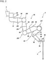
FIG. 2 is a diagram illustrating a view of a configuration of a manipulator arm of a surgical system, such as being illustrated inFIG. 1 ; -
FIG. 3 is a block diagram illustrating a view of a configuration of a control system of a surgical system, such as being illustrated inFIG. 1 ; -
FIG. 4 is a diagram illustrating a front view of a configuration of an arm base, such as being illustrated inFIG. 1 ; -
FIG. 5 is a diagram illustrating a plan view of the arm base, such as being illustrated inFIG. 4 ; -
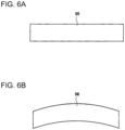
FIG. 6A is a diagram illustrating a front view of a modification of the arm base; and -
FIG. 6B is a diagram illustrating a front view of another modification of the arm base. - Descriptions are provided hereinbelow for one or more embodiments based on the drawings. In the respective drawings referenced herein, the same constituents are designated by the same reference numerals and duplicate explanation concerning the same constituents is omitted. All of the drawings are provided to illustrate the respective examples only.
- A surgical system according to one or more embodiments is described below with reference to the drawings. The following surgical system according to one or more embodiments is merely an example(s). Thus, the invention is not limited to the following one or more embodiments, and addition, deletion, and modification can be made within the intent of the invention.
- As illustrated in
FIG. 1 , asurgical system 100 is a system for a surgeon such as a doctor to perform endoscopic surgery on a patient with a medical manipulator 1, like robotic-assistant surgery and robotic telesurgery or robotic remote surgery. - The
surgical system 100 includes the medical manipulator 1 as a patient-side system and aninstruction apparatus 2 for controllingmanipulator arms 3 with multi-degree of freedom (hereinafter, simply referred to as arms) of the medical manipulator 1. Theinstruction apparatus 2 is disposed apart from the medical manipulator 1, and thearms 3 are remotely controlled by theinstruction apparatus 2. The surgeon inputs an action to be executed by thearms 3 to theinstruction apparatus 2, and theinstruction apparatus 2 transmits the action instruction to the medical manipulator 1. The medical manipulator 1 receives the action instruction transmitted from theinstruction apparatus 2. Based on the received action instruction, the medical manipulator 1 operates a medical tool 4 in an elongated shaft shape, such as an endoscope assembly and instrument, held by thearms 3 of the medical manipulator 1. - The
instruction apparatus 2 is an apparatus constructing an interface between thesurgical system 100 and the surgeon so as to control thearms 3. Theinstruction apparatus 2 may be disposed inside or outside of a surgery room. Theinstruction apparatus 2 includesoperation manipulator arms 51 to which the surgeon inputs the action instruction,operation pedals 52, atouch panel 53, amonitor 54 displaying an image captured by the endoscope assembly, asupport arm 55 supporting themonitor 54 at the height of the face of the operator such as a doctor, abar 56 on which thetouch panel 53 is mounted, and the like. The surgeon operates theoperation manipulator arms 51 and theoperation pedals 52 to input the action instruction to theinstruction apparatus 2 while visually checking an affected area or an involve part through themonitor 54. The action instruction inputted to theinstruction apparatus 2 is transmitted to acontroller 6 of the medical manipulator 1 through wired or wireless communication. Operation of thearms 3 is controlled by thecontroller 6. Thecontroller 6 may be formed of a computer such as a microcomputer, for example. - The medical manipulator 1 constructs an interface between the
surgical system 100 and the patient. The medical manipulator 1 is disposed inside the surgery room that is sterilized to be a sterile field. - The medical manipulator 1 includes a
positioner 7, anelongated arm base 5 attached to a tip end portion or a distal end portion of thepositioner 7, and the multiple arms (in this embodiment, four arms) 3 that include base end portions detachably attached to thearm base 5. The medical manipulator 1 is configured to make an accommodation posture in which thearms 3 are folded. The fourarms 3 are referred to asarms arms arm base 5. - The
positioner 7 is formed as a vertical articulated robot and provided on abase body 70a of awagon 70 disposed at a predetermined location in the surgery room. Thepositioner 7 can move the position of thearm base 5 three-dimensionally. Thepositioner 7 and thearm base 5 are covered with not-illustrated sterile drapes and shielded from the sterile field in the surgery room. Atouch panel display 48 as an operation input unit is provided on ahandle 74 of thewagon 70. Thetouch panel display 48 is configured to display information data related to the state of the medical manipulator 1, information on specific surgery, and information on the entiresurgical system 100. Thetouch panel display 48 is for giving an instruction to move the base end portions of thearms arm base 5. In addition, thetouch panel display 48 is configured as an input device that receives input of operation of thepositioner 7 of the medical manipulator 1. That is, thetouch panel display 48 is configured to give an instruction to move thearm base 5 by thepositioner 7. - A distal end portion of an
arm 3A out of thearms 3 holds, for example, a replacement instrument (for example, a pair of forceps and so on) as the medical tool 4. A distal end portion of anarm 3B holds an instrument such as a pair of forceps as the medical tool 4, for example. A distal end portion of anarm 3C holds the endoscope assembly as the medical tool 4, for example. A distal end portion of anarm 3D holds a replacement endoscope assembly as the medical tool 4, for example. - In the medical manipulator 1, the
arm base 5 has a function as a hub of thearms 3. In this embodiment, thepositioner 7 and thearm base 5 form a manipulator arm support body S that movably supports thearms 3. It should be noted that, it is acceptable if the manipulator arm support body S includes at least thearm base 5 without thepositioner 7. Such anarm base 5 may be supported by a direct-acting rail, an elevating device, or a bracket attached to a sealing or a wall instead of thepositioner 7 to form a manipulator arm support body S. - In the medical manipulator 1, the elements from the
positioner 7 to the medical tool 4 are connected in series. Hereinafter, in each of the series of elements in this specification, an end portion close to thepositioner 7 is referred to as a base end portion or proximal end portion, and an end portion on the opposite side is referred to as a distal end portion. - As illustrated in
FIG. 2 , when the medical tool 4 is an instrument, the medical tool 4 includes adrive unit 89 provided on the base end portion of the medical tool 4. An end effector provided on the distal end portion of the instrument is selected from a group including equipment having a movable joint (for example, pair of forceps, pair of scissors, grasper, needle holder, micro dissector, staple applier, tacker, suction and irrigation tool, snare wire, clip applier, and so on) and equipment having no joints (for example, cutting blade, ablation probe, irrigation device, catheter, suction orifice, and so on). - In the procedure using the medical manipulator 1, first, the
controller 6 that receives the action instruction from thetouch panel display 48 positions thearm base 5 by moving thepositioner 7 so as to put thearm base 5 and a surgical bed or the patient in a predetermined position relationship. Next, thecontroller 6 positions the medical tool 4 by moving thearms 3 so as to put a sleeve (cannula sleeve) placed on the body surface of the patient and the medical tool 4 in a predetermined initial position relationship. Additionally, the distances between the base end portions of thearms 3 are properly adjusted with thearms 3 slid by thecontroller 6. The details are described below. The positioning by means of thepositioner 7 and the positioning by means of thearms 3 may be performed concurrently. Thecontroller 6 controls, based on the action instruction from theinstruction apparatus 2, thearms 3 to operate the medical tool 4 while keeping thepositioner 7 still as a general rule, to properly perform displacement and orientation changing of the medical tool 4 for medical procedures. - Next, details of the configuration of each
arm 3 are described. As illustrated inFIG. 2 , thearm 3 includes anarm body 30 and atranslation arm 35 connected to the distal end portion of thearm body 30, and thearm 3 is configured to be capable of moving the distal end portion thereof with respect to the base end portion thereof in a three-dimensional space. In an embodiment illustrated in the drawings, thearms 3 provided to the medical manipulator 1 are all have the same or similar configurations; however, at least one of thearms 3 may have a different configuration from the configurations of the others. Aholder 36 capable of holding the medical tool 4 is provided to the distal end portion of thearm 3. - The
arm 3 is configured to be attachable to and detachable from thearm base 5. Thearm 3 has resistances for cleaning processing and sterile processing, including water resistance, heat resistance, and chemical resistance. There are various ways for the sterile processing of thearm 3. For example, autoclave sterilization, EOG sterilization, chemical sterilization with an antiseptic, and so on may be selectively used. - The
arm body 30 includes a base 80 detachably attached to thearm base 5 and afirst link 81 to asixth link 86 connected with one another in order from the base 80 to the distal end portion of thearm 30. More specifically, the base end portion of thefirst link 81 is connected to the distal end portion of the base 80 with a twist joint J31 arranged therebetween. The base end portion of thesecond link 82 is connected to the distal end portion of thefirst link 81 with a twist joint J32 arranged therebetween. The base end portion of thethird link 83 is connected to the distal end portion of thesecond link 82 with a bending joint J33 arranged therebetween. The base end portion of thefourth link 84 is connected to the distal end portion of thethird link 83 with a twist joint J34 arranged therebetween. The base end portion of thefifth link 85 is connected to the distal end portion of thefourth link 84 with a bending joint J35 arranged therebetween. The base end portion of thesixth link 86 is connected to the distal end portion of thefifth link 85 with a twist joint J36 arranged therebetween. The base end portion of thetranslation arm 35 is connected to the distal end portion of thesixth link 86 with a bending joint J37 arranged therebetween. Thus, thearm 3 is formed as a seven-axial joint arm including a redundant axis (in this embodiment, the twist joint J32). In other words, thearm 3 has six or more degrees of freedom. Consequently, thearm 3 can change or transform the posture or the shape thereof without changing the position of the distal end portion of thearm 3. - An outer shell of the
arm body 30 is formed of a member that has heat resistance and chemical resistance, such as stainless, for example. Connection portions (or joint portions) between the links are provided with sealing (not illustrated) to provide water resistance. The sealing also has the heat resistance for autoclaved sterilization and chemical resistance for antiseptic. In each connection portion between the links, an end portion of one link is inserted into an end portion of the other link to be connected with the one link, and the sealing is arranged so as to fill the space between the end portions of the links. Thus, the sealing is hidden from external appearance. In this way, entering of water, chemical liquid, and vapor through the space between the sealing and the link is suppressed. - The
translation arm 35 moves theholder 36, which is attached to the distal end portion of thetranslation arm 35, in the axial direction of the medical tool 4, and thus translationally moves the medical tool 4 attached to theholder 36 in the axial direction of the medical tool 4. - The
translation arm 35 includes a baseend side link 61 that is connected to the distal end portion of thesixth link 86 of thearm body 30 with the bending joint J37 arranged therebetween, a distalend side link 62, aconnection shaft 63 connecting the baseend side link 61 and the distalend side link 62, and a not-illustrated interlocking mechanism. In addition, apivot shaft 68 is provided to the distal end portion of thetranslation arm 35, which is the distal end portion of the distalend side link 62. A drive source of thetranslation arm 35 is provided to the distal end portion of thearm body 30, or thesixth link 86. Theconnection shaft 63 is arranged parallel to the bending joint J37, and the distalend side link 62 is configured to be pivotable about theconnection shaft 63 with respect to the baseend side link 61. A known link mechanism can be employed as the above-mentioned interlocking mechanism. For example, the interlocking mechanism may have a configuration using a pulley and a timing belt and may be a mechanism including a gear train. - A first translation arm drive shaft and a second translation arm drive shaft (both are not illustrated) arranged coaxially with the bending joint J37 are provided to the base end portion of the distal end side link 62 (connection portion between the distal
end side link 62 and the sixth link 86). The second translation arm drive shaft is connected to the interlocking mechanism. With the second translation arm drive shaft differentially moving with respect to the first translation arm drive shaft, thetranslation arm 35 is translated such that the pivot angle of the baseend side link 61 about the bending joint J37, the pivot angle of the distalend side link 62 about theconnection shaft 63, and the pivot angle of theholder 36 about thepivot shaft 68 are fixed to be in a predetermined ratio (for example, 1 :2:1). As the first translation arm drive shaft and the second translation arm drive shaft are synchronized with each other to pivot, the entirety of thetranslation arm 35 pivots about the bending joint J37 with respect to thearm body 30. - As illustrated in
FIG. 3 , thearm body 30 is provided with driving servomotors M31 to M36, encoders E31 to E36 detecting the rotation angles of the servomotors M31 to M36, and reduction drives (not illustrated) reducing the outputs of the servomotors M31 to M36 to increase the torque, with each corresponding to the joints J31 to J36. Among the joints J31 to J36 inFIG. 3 , the control systems of the twist joint J31 and the twist joint J36 are illustrated as a representative, and the control systems of the other joints J33 to J35 are omitted. In addition, thearm body 30 is provided with a servomotor M37a for driving the first translation arm drive shaft and a servomotor M37b for driving the second translation arm drive shaft, encoders E37a and E37b detecting the rotation angles of the servomotors M37a and M37b, and reduction drives (not illustrated) reducing the outputs of the servomotors M37a and M37b to increase the torque, with each corresponding to the joint J37 that allows thetranslation arm 35 to perform the translation movement or the pivot movement. - The encoders E31 to E36, E37a, and E37b are provided as an example of rotation position detection units for detecting the rotation positions (rotation angles) of the servomotors M31 to M36, M37a, and M37b. Rotation position detection units such as resolvers may be used instead of the encoders E31 to E36, E37a, and E37b. The above-described elements of the drive systems of the
arm 3 and wirings and control units for the elements are made of high-temperature resistant materials and have the heat resistance for sterile processing. - The
controller 6 includes anarm control unit 601 that controls movements of the arms 3 (movement other than sliding movement) based on the action instruction and an arm slidingcontrol unit 610 that controls sliding movements of thearms 3. Servo-control units C31 to C36, C37a and C37b are electrically connected to thearm control unit 601, and the servomotors M31 to M36, M37a, and M37b are electrically connected to thearm control unit 601 via not-illustrated amplifier circuits. - Based on the action instruction inputted to the
instruction apparatus 2, a position and orientation instruction of the distal end portion of thearm 3 is inputted to thearm control unit 601. Based on the rotation angles detected by the encoders E31 to E36, E37a, and E37b, thearm control unit 601 generates position instruction values and outputs the thus-generated position instruction values. The servo-control units C31 to C36, C37a and C37b receive the position instruction values, and then generate drive instruction values (torque instruction values) based on the rotation angles detected by the encoders E31 to E36, E37a, and E37b and the received position instruction values and output the thus-generated drive instruction values. The amplifier circuits receive the drive instruction values, and then supply drive currents corresponding to the received drive instruction values to the servomotors M31 to M36, M37a, and M37b. As described above, the servomotors M31 to M36, M37a, and M37b are servo-controlled such that the distal end portion of thearm 3 is set at the position and orientation corresponding to the position and orientation instruction. - The
controller 6 includes astorage unit 602 that is capable of reading out data to thearm control unit 601. Thestorage unit 602 stores surgery information that is inputted through theinstruction apparatus 2 or thetouch panel display 48 in advance. - The
storage unit 602 stores information such as the length of the medical tool 4 held by the distal end portion of thearm 3. This allows thearm control unit 601 to grasp the position of the distal end portion of the medical tool 4 held by the distal end portion of thearm 3 based on the position and orientation instruction of the distal end portion of thearm 3. In addition, thestorage unit 602 stores processing data for processing of determining the interference between thearms 3. - The
arm control unit 601 is configured to control the actions of thearms 3 based on the action instruction from theinstruction apparatus 2 during the surgery using thesurgical system 100. In this process, thearm control unit 601 uses the above-described processing data stored in thestorage unit 602 to perform the processing of determining whether thearms 3 will interfere with each other. In order to avoid the interference, thearm control unit 601 is configured to control the actions of thearms 3 when it is determined that thearms 3 will interfere with each other. - In order to avoid the interference between the
arms 3, during the setup stage before the surgery, the arm slidingcontrol unit 610 previously changes the distance between the base end portions of thearms 3 based on the action instruction generated by a surgery assistant operating thetouch panel display 48 depending on a condition such as the surgical method. In addition, in order to avoid the interference between thearms 3 during surgery, the arm slidingcontrol unit 610 performs the interference determination processing using the above-described processing data stored in thestorage unit 602 based on the action instruction from theinstruction apparatus 2 operated by the doctor. The arm slidingcontrol unit 610 is configured to change the distance between the base end portions of thearms 3 to avoid the interference when it is determined that thearms 3 will interfere with each other. - Next, a configuration of the
arm base 5 and a configuration for changing the distance between the base end portions of thearms 3 are described. As illustrated inFIG. 4 , thearm base 5 includes twomovement mechanisms 47. Themovement mechanism 47 includes a first moving mechanism 47A for changing a distance between a base end portion of thearm 3A on one end side of the fourarms 3 and a base end portion of thearm 3B adjacent thereto. The first moving mechanism 47A is disposed on aninclined portion 5c described later for moving thearm 3A, and the second moving mechanism 47B is disposed on aninclined portion 5b described later for moving thearm 3D. The detailed description is given below. - As illustrated in
FIG. 4 , thearm base 5 is formed in a substantially V-shape in front view. Specifically, thearm base 5 includes an elongatedbase body portion 5a andinclined portions base body portion 5a. Theinclined portion 5b is integrally connected to a second end portion 5a2 (right end inFIG. 4 ) of thebase body portion 5a, and theinclined portion 5c is integrally connected to a first end portion 5a1 (left end inFIG. 4 ) of thebase body portion 5a. Theinclined portion 5b is inclined in a direction closer to the patient when thebase body portion 5a is arranged at a position facing the patient. Theinclined portion 5c is inclined in the direction closer to the patient when thebase body portion 5a is arranged at the position facing the patient. With this configuration, thearm base 5 has a shape that allows thearm base 5 to be placed along the curve of the abdomen of the patient when thearm base 5 is arranged at the position facing the abdomen of the patient. - In this case, in this embodiment, the
arm 3B and thearm 3C out of the fourarms 3 are fixed to the arm base 5 (base body portion 5a of arm base 5). On the other hand, thearm 3D is provided to thearm base 5 slidably in the inclining direction of theinclined portion 5b, and thearm 3A is provided to thearm base 5 slidably in the inclining direction of theinclined portion 5c. In other words, thearm 3D is configured to be moved in directions closer to and farther from thearm 3C next to thearm 3D, and thearm 3A is configured to be moved in directions closer to and farther from thearm 3B next to thearm 3A. - The
arm base 5 is formed like a casing, and the above-described movement mechanisms 47A, 47B are disposed inside thearm base 5. Specifically, the movement mechanisms 47A, 47B include fourrollers 40, a slidingbelt 41 rotatably installed over the fourrollers 40 in a tensioned state, aconnection member 42 connecting the slidingbelt 41 and thearm 3D, a drive motor 611 (seeFIG. 5 ), and a drive belt 45 (seeFIG. 5 ). In addition, a reduction drive (not illustrated) for reducing the output of thedrive motor 611 and an encoder (not illustrated) for detecting the rotation angle of thedrive motor 611 are provided. - Each
roller 40 is arranged at a position of a vertex of a rectangular shape so as to install the slidingbelt 41 in a tensioned state in the rectangular shape in front view. Theconnection member 42 is connected to a part of the slidingbelt 41 that is installed over in a tensioned state a pair of the rollers 40 (a pair of therollers 40 on lower side inFIG. 4 ) arranged in the inclining direction of theinclined portion 5b. As illustrated inFIG. 5 , thedrive belt 45 is installed over in a tensioned state a rotation shaft of thedrive motor 611 and one of the rollers 40 (aroller 40 on upper left inFIG. 4 ). In other words, the upperleft roller 40 inFIG. 4 is configured as a drive roller, and the other threerollers 40 are configured as driven rollers. - In the above-described configuration, when the distance between the base end portion of the
arms 3D and the base end portion of thearms 3C is to be changed, therollers 40 are rotated using thedrive belt 45 clockwise or counter-clockwise with thedrive motor 611 driven by the arm slidingcontrol unit 610. Thus the slidingbelt 41 is rotated, and thereby theconnection member 42 is moved in one side or the other side of the inclining direction of theinclined portion 5b. This allows thearm 3D to be slid along the inclining direction of theinclined portion 5b. Consequently, it is possible to move thearm 3D in the directions closer to and father away from thearm 3C and to change the distance between the base end portion of thearm 3D and the base end portion of thearm 3C. Since a configuration of sliding thearm 3A along the inclining direction of theinclined portion 5c using the movement mechanism 47A is same as or similar to the configuration of sliding thearm 3D using the movement mechanism 47B, additional description is omitted. - As described above, according to the
surgical system 100 including the medical manipulator 1 of an embodiment, themovement mechanism 47 can slide thearm 3D to change the distance between the base end portion of thearm 3D and the base end portion of thearm 3C, and can slide thearm 3A to change the distance between the base end portion of thearm 3A and the base end portion of thearm 3B. This makes it possible to increase the degrees of freedom of arrangement of thearms 3 arranged for the patient depending on the surgical method and to avoid the interference between thearms 3. - In an embodiment, the
arm base 5 is formed in a substantially V-shaped. This makes the approach of thearms 3 to the patient easy. - In an embodiment, the
movement mechanism 47 is configured to allow changing of the distance between the base end portions of thearms 3 during surgery. This makes it possible to change the distance between the base end portions of thearms 3 and to avoid the interference between thearms 3 even when, for example, an unexpected urgent response is required. - In addition to the above-described one or more embodiments, the following various modifications can be made without departing from the scope of appended claims.
- The
arm base 5 is formed in a substantially V-shape in front view in the above-described one or more embodiments; however, it is not limited thereto. For example, anarm base 55 formed in a straight line shape in front view as illustrated inFIG. 6A may be employed, or anarm base 56 formed in an arc shape in front view as illustrated inFIG. 6B may be employed. The configuration ofFIG. 6B makes the approach of thearm 3 to the patient easy. In addition, thearm base 5 may be formed to be folded at the middle in the longitudinal direction like a mountain shape. - Only the
arms arms 3 are configured to be slidable in the above-described one or more embodiments; however, it is not limited thereto. The fourarms 3 may be all configured to be slidable. - The
movement mechanism 47 that is configured to slide thearms belt 41 is employed in the above-described one or more embodiments; however, it is not limited thereto. For example, themovement mechanism 47 may be formed of a different actuator, such as a cylinder, or the like. - The invention includes other embodiments in addition to the above-described one or more embodiments without departing from the subject-matter of the invention. The embodiments are to be considered in all respects as illustrative, and not restrictive. The scope of the invention is indicated by the appended claims rather than by the foregoing descriptions. Hence, all configurations including the meaning and range within equivalent arrangements of the claims are intended to be embraced in the invention.
Claims (14)
- A medical manipulator (1), comprising:a first manipulator arm (3A) with multi-degree of freedom that holds a medical tool (4) at a distal end portion thereof;a second manipulator arm (3B) with multi-degree of freedom that holds a medical tool (4) at a distal end portion thereof;an arm base (5) that holds base end portions of the first and second manipulator arms;a movement mechanism (47) configured to move the base end portion of the first manipulator arm with respect to the arm base to change a distance between the base end portion of the first manipulator arm and the base end portion of the second manipulator arm; anda positioner (7) configured to move the arm base and position the arm base in place,characterized in thatthe movement mechanism (47) includes a plurality of rollers (40), a sliding belt (41) rotatably installed over the rollers, a drive motor (611) for rotating one roller of the plurality of rollers and a connection member (42) connecting the sliding belt and the base end portion of the first manipulator arm; and 1wherein the second manipulator arm is fixed to the arm base.
- The medical manipulator according to claim 1, further comprising:a third manipulator arm (3C) with multi-degree of freedom that holds a medical tool by a distal end portion thereof; anda fourth manipulator arm (3D) with multi-degree of freedom that holds a medical tool by a distal end portion thereof, whereinthe first to fourth manipulator arms are held by the arm base and arranged in the recited order in a longitudinal direction of the arm base, andthe movement mechanism is configured to move a base end portion of the fourth manipulator arm with respect to the arm base to change a distance between a base end portion of the third manipulator arm and the base end portion of the fourth manipulator arm,wherein the movement mechanism includes a second plurality of rollers (40), a second sliding belt (41) rotatably installed over the second rollers, a second drive motor (611) for rotating one roller of the second plurality of rollers and a second connection member (42) connecting the second sliding belt and the base end portion of the fourth manipulator arm.
- The medical manipulator according to claim 2, whereinthe arm base includes a base body portion (5a) , a first inclined portion (5c) that is connected to a first end portion (5a1) of the base body portion with inclined with respect to the base body portion, and a second inclined portion (5b) that is connected to a second end portion (5a2) of the base body portion with inclined with respect to the base body portion, whereinthe first inclined portion holds the first manipulator arm, the base body portion holds the second and third manipulator arms, and the second inclined portion holds the fourth manipulator arm.
- The medical manipulator according to claim 3, whereinthe movement mechanism includes a first movement mechanism (47A) and a second movement mechanism (47B),the first movement mechanism is arranged in the first inclined portion to move the first manipulator arm with respect to the arm base, andthe second movement mechanism is arranged in the second inclined portion to move the fourth manipulator arm with respect to the arm base,wherein the first movement mechanism (47A) includes the plurality of rollers, the sliding belt, the drive motor and the connection member, andthe second movement mechanism (47B) includes the second plurality of rollers, the second sliding belt, the second drive motor and the second connection member.
- The medical manipulator according to any one of claims 1 to 4, wherein
each of the first and second manipulator arms has six or more degrees of freedom. - The medical manipulator according to any one of claims 1 to 5, further comprising
a control unit that controls the movement mechanism to move the base end portion of the first manipulator arm with respect to the arm base to avoid interference between the first manipulator arm and the second manipulator arm during surgery. - The medical manipulator according to any one of claims 1 to 6, wherein
the positioner comprises a vertical articulated robot. - The medical manipulator according to any one of claims 1 to 7, further comprising:
an operation input unit (48) that issues an instruction to move the base end portion of the first manipulator arm with respect to the arm base. - The medical manipulator according to claim 8, wherein
the operation input unit issues an instruction to cause the positioner to move the arm base. - The medical manipulator according to any one of claims 1 to 9, wherein
the medical manipulator is configured to be transformed in an accommodation posture in which the first and second manipulator arms are folded. - A surgical system, comprising:the medical manipulator according to any one of claims 1 to 10 44 ; andan instruction apparatus (2) that instructs actions of the first and second manipulator arms.
- The surgical system according to claim 11; wherein
the instruction apparatus includes first and second operation manipulator arms (51) to respectively operate the first and second manipulator arms of the medical manipulator. - The surgical system according to claim 11 or 12, whereinone of the first manipulator arm and the second manipulator arm holds at the distal end portion thereof an endoscope as the medical tool, andthe instruction apparatus includes a monitor (54) configured to display an image captured by the endoscope.
- The medical manipulator according to any one of claims 1 to 12 wherein the arm base is formed at least partly in a straight line shape.
Applications Claiming Priority (2)
| Application Number | Priority Date | Filing Date | Title |
|---|---|---|---|
| JP2018189768 | 2018-10-05 | ||
| JP2019171985A JP6894954B2 (en) | 2018-10-05 | 2019-09-20 | Medical manipulator and surgical system equipped with it |
Publications (3)
| Publication Number | Publication Date |
|---|---|
| EP3632361A1 EP3632361A1 (en) | 2020-04-08 |
| EP3632361B1 true EP3632361B1 (en) | 2024-06-26 |
| EP3632361B8 EP3632361B8 (en) | 2024-07-31 |
Family
ID=68158978
Family Applications (1)
| Application Number | Title | Priority Date | Filing Date |
|---|---|---|---|
| EP19201543.6A Active EP3632361B8 (en) | 2018-10-05 | 2019-10-04 | Medical manipulator and surgical system including the same |
Country Status (2)
| Country | Link |
|---|---|
| US (1) | US11648067B2 (en) |
| EP (1) | EP3632361B8 (en) |
Families Citing this family (2)
| Publication number | Priority date | Publication date | Assignee | Title |
|---|---|---|---|---|
| CN112690881B (en) * | 2021-03-24 | 2021-06-18 | 真实维度科技控股(珠海)有限公司 | A kind of auxiliary guidance and positioning device for CT puncture |
| JP7393383B2 (en) * | 2021-05-24 | 2023-12-06 | 川崎重工業株式会社 | Operation method of surgical support robot and articulated robot |
Family Cites Families (19)
| Publication number | Priority date | Publication date | Assignee | Title |
|---|---|---|---|---|
| US8004229B2 (en) | 2005-05-19 | 2011-08-23 | Intuitive Surgical Operations, Inc. | Software center and highly configurable robotic systems for surgery and other uses |
| GB2417090A (en) | 2003-04-28 | 2006-02-15 | Stephen James Crampton | CMM arm with exoskeleton |
| GB0309662D0 (en) | 2003-04-28 | 2003-06-04 | Crampton Stephen | Robot CMM arm |
| JP4188855B2 (en) * | 2004-02-23 | 2008-12-03 | 川崎重工業株式会社 | Control device |
| US7763015B2 (en) | 2005-01-24 | 2010-07-27 | Intuitive Surgical Operations, Inc. | Modular manipulator support for robotic surgery |
| DE102007045075B4 (en) * | 2007-09-21 | 2010-05-12 | Siemens Ag | Interventional medical diagnosis and / or therapy system |
| KR100944412B1 (en) | 2008-10-13 | 2010-02-25 | (주)미래컴퍼니 | Surgical slave robot |
| WO2010068005A2 (en) | 2008-12-12 | 2010-06-17 | Rebo | Surgical robot |
| JP2012005557A (en) | 2010-06-23 | 2012-01-12 | Terumo Corp | Medical robot system |
| CN103648425B (en) | 2011-08-04 | 2016-10-19 | 奥林巴斯株式会社 | Medical manipulator and surgery support device |
| EP2785267B1 (en) | 2011-11-30 | 2022-01-12 | Titan Medical Inc. | Apparatus and method for supporting a robotic arm |
| DE102012025100A1 (en) * | 2012-12-20 | 2014-06-26 | avateramedical GmBH | Decoupled multi-camera system for minimally invasive surgery |
| JP6349853B2 (en) | 2013-06-27 | 2018-07-04 | 株式会社デンソーウェーブ | Industrial robot |
| EP3119334B1 (en) | 2014-03-17 | 2022-01-26 | Intuitive Surgical Operations, Inc. | Structural adjustment systems and methods for a teleoperational medical system |
| US10130436B2 (en) | 2014-03-17 | 2018-11-20 | Intuitive Surgical Operations, Inc. | Automated structure with pre-established arm positions in a teleoperated medical system |
| KR102356213B1 (en) | 2014-03-17 | 2022-01-28 | 인튜어티브 서지컬 오퍼레이션즈 인코포레이티드 | Guided setup for teleoperated medical device |
| WO2015142798A1 (en) | 2014-03-17 | 2015-09-24 | Intuitive Surgical Operations, Inc. | Methods and devices for tele-surgical table registration |
| PL3146930T3 (en) * | 2015-09-22 | 2018-10-31 | Fundacja Rozwoju Kardiochirurgii Im. Prof. Zbigniewa Religi | A surgical robot's tool arms assembly |
| CN106236276B (en) | 2016-09-28 | 2019-09-17 | 微创(上海)医疗机器人有限公司 | Surgical robot system |
-
2019
- 2019-10-01 US US16/589,144 patent/US11648067B2/en active Active
- 2019-10-04 EP EP19201543.6A patent/EP3632361B8/en active Active
Also Published As
| Publication number | Publication date |
|---|---|
| US20200107890A1 (en) | 2020-04-09 |
| US11648067B2 (en) | 2023-05-16 |
| EP3632361B8 (en) | 2024-07-31 |
| EP3632361A1 (en) | 2020-04-08 |
Similar Documents
| Publication | Publication Date | Title |
|---|---|---|
| US11801103B2 (en) | Surgical system and method of controlling surgical system | |
| JP6654883B2 (en) | Surgical system, manipulator arm, and manipulator arm support | |
| JP6585067B2 (en) | Alignment and engagement for remotely operated surgical instruments | |
| KR102172694B1 (en) | Multiport surgical robotic system architecture | |
| KR102322620B1 (en) | Redundant axis and degree of freedom for hardware-constrained remote center robotic manipulator | |
| JP7402894B2 (en) | Surgical operation system and method for controlling surgical operation manipulator arm | |
| JP6654884B2 (en) | Surgery system | |
| US12616360B2 (en) | Manipulator arm and patient-side system for surgical system | |
| JP2017513550A (en) | Method and apparatus for telesurgical table alignment | |
| US12029518B2 (en) | Method of controlling surgical system and surgical system | |
| CN108882969B (en) | surgical system | |
| KR20180090331A (en) | Surgical Surgical System | |
| US12171513B2 (en) | Surgical system and patient-side apparatus | |
| US11648067B2 (en) | Medical manipulator and surgical system including the same | |
| US20220175479A1 (en) | Surgical operation system and method of controlling surgical operation system | |
| JP7345008B2 (en) | Methods for translating manipulator arms, robotic systems and surgical instruments used in surgical systems | |
| JP6894954B2 (en) | Medical manipulator and surgical system equipped with it | |
| JP7017616B2 (en) | Patient-side equipment and surgical system of surgical system | |
| US11717366B2 (en) | Medical manipulator | |
| JP2006312079A (en) | Medical manipulator | |
| CN121013689A (en) | Controlled ultrasonic sealing and cutting systems and methods | |
| JP7393383B2 (en) | Operation method of surgical support robot and articulated robot | |
| KR20180090330A (en) | Surgical Surgical System |
Legal Events
| Date | Code | Title | Description |
|---|---|---|---|
| PUAI | Public reference made under article 153(3) epc to a published international application that has entered the european phase |
Free format text: ORIGINAL CODE: 0009012 |
|
| STAA | Information on the status of an ep patent application or granted ep patent |
Free format text: STATUS: THE APPLICATION HAS BEEN PUBLISHED |
|
| AK | Designated contracting states |
Kind code of ref document: A1 Designated state(s): AL AT BE BG CH CY CZ DE DK EE ES FI FR GB GR HR HU IE IS IT LI LT LU LV MC MK MT NL NO PL PT RO RS SE SI SK SM TR |
|
| AX | Request for extension of the european patent |
Extension state: BA ME |
|
| STAA | Information on the status of an ep patent application or granted ep patent |
Free format text: STATUS: REQUEST FOR EXAMINATION WAS MADE |
|
| 17P | Request for examination filed |
Effective date: 20201006 |
|
| RBV | Designated contracting states (corrected) |
Designated state(s): AL AT BE BG CH CY CZ DE DK EE ES FI FR GB GR HR HU IE IS IT LI LT LU LV MC MK MT NL NO PL PT RO RS SE SI SK SM TR |
|
| GRAP | Despatch of communication of intention to grant a patent |
Free format text: ORIGINAL CODE: EPIDOSNIGR1 |
|
| STAA | Information on the status of an ep patent application or granted ep patent |
Free format text: STATUS: GRANT OF PATENT IS INTENDED |
|
| INTG | Intention to grant announced |
Effective date: 20240125 |
|
| GRAS | Grant fee paid |
Free format text: ORIGINAL CODE: EPIDOSNIGR3 |
|
| GRAA | (expected) grant |
Free format text: ORIGINAL CODE: 0009210 |
|
| STAA | Information on the status of an ep patent application or granted ep patent |
Free format text: STATUS: THE PATENT HAS BEEN GRANTED |
|
| AK | Designated contracting states |
Kind code of ref document: B1 Designated state(s): AL AT BE BG CH CY CZ DE DK EE ES FI FR GB GR HR HU IE IS IT LI LT LU LV MC MK MT NL NO PL PT RO RS SE SI SK SM TR |
|
| REG | Reference to a national code |
Ref country code: GB Ref legal event code: FG4D |
|
| REG | Reference to a national code |
Ref country code: CH Ref legal event code: EP |
|
| REG | Reference to a national code |
Ref country code: DE Ref legal event code: R096 Ref document number: 602019054112 Country of ref document: DE |
|
| REG | Reference to a national code |
Ref country code: CH Ref legal event code: PK Free format text: BERICHTIGUNG B8 |
|
| RAP2 | Party data changed (patent owner data changed or rights of a patent transferred) |
Owner name: KAWASAKI JUKOGYO KABUSHIKI KAISHA |
|
| PG25 | Lapsed in a contracting state [announced via postgrant information from national office to epo] |
Ref country code: BG Free format text: LAPSE BECAUSE OF FAILURE TO SUBMIT A TRANSLATION OF THE DESCRIPTION OR TO PAY THE FEE WITHIN THE PRESCRIBED TIME-LIMIT Effective date: 20240626 |
|
| PG25 | Lapsed in a contracting state [announced via postgrant information from national office to epo] |
Ref country code: HR Free format text: LAPSE BECAUSE OF FAILURE TO SUBMIT A TRANSLATION OF THE DESCRIPTION OR TO PAY THE FEE WITHIN THE PRESCRIBED TIME-LIMIT Effective date: 20240626 Ref country code: FI Free format text: LAPSE BECAUSE OF FAILURE TO SUBMIT A TRANSLATION OF THE DESCRIPTION OR TO PAY THE FEE WITHIN THE PRESCRIBED TIME-LIMIT Effective date: 20240626 |
|
| REG | Reference to a national code |
Ref country code: LT Ref legal event code: MG9D |
|
| PG25 | Lapsed in a contracting state [announced via postgrant information from national office to epo] |
Ref country code: GR Free format text: LAPSE BECAUSE OF FAILURE TO SUBMIT A TRANSLATION OF THE DESCRIPTION OR TO PAY THE FEE WITHIN THE PRESCRIBED TIME-LIMIT Effective date: 20240927 |
|
| PG25 | Lapsed in a contracting state [announced via postgrant information from national office to epo] |
Ref country code: LV Free format text: LAPSE BECAUSE OF FAILURE TO SUBMIT A TRANSLATION OF THE DESCRIPTION OR TO PAY THE FEE WITHIN THE PRESCRIBED TIME-LIMIT Effective date: 20240626 |
|
| REG | Reference to a national code |
Ref country code: NL Ref legal event code: MP Effective date: 20240626 |
|
| PG25 | Lapsed in a contracting state [announced via postgrant information from national office to epo] |
Ref country code: NO Free format text: LAPSE BECAUSE OF FAILURE TO SUBMIT A TRANSLATION OF THE DESCRIPTION OR TO PAY THE FEE WITHIN THE PRESCRIBED TIME-LIMIT Effective date: 20240926 Ref country code: LV Free format text: LAPSE BECAUSE OF FAILURE TO SUBMIT A TRANSLATION OF THE DESCRIPTION OR TO PAY THE FEE WITHIN THE PRESCRIBED TIME-LIMIT Effective date: 20240626 Ref country code: HR Free format text: LAPSE BECAUSE OF FAILURE TO SUBMIT A TRANSLATION OF THE DESCRIPTION OR TO PAY THE FEE WITHIN THE PRESCRIBED TIME-LIMIT Effective date: 20240626 Ref country code: GR Free format text: LAPSE BECAUSE OF FAILURE TO SUBMIT A TRANSLATION OF THE DESCRIPTION OR TO PAY THE FEE WITHIN THE PRESCRIBED TIME-LIMIT Effective date: 20240927 Ref country code: FI Free format text: LAPSE BECAUSE OF FAILURE TO SUBMIT A TRANSLATION OF THE DESCRIPTION OR TO PAY THE FEE WITHIN THE PRESCRIBED TIME-LIMIT Effective date: 20240626 Ref country code: BG Free format text: LAPSE BECAUSE OF FAILURE TO SUBMIT A TRANSLATION OF THE DESCRIPTION OR TO PAY THE FEE WITHIN THE PRESCRIBED TIME-LIMIT Effective date: 20240626 Ref country code: RS Free format text: LAPSE BECAUSE OF FAILURE TO SUBMIT A TRANSLATION OF THE DESCRIPTION OR TO PAY THE FEE WITHIN THE PRESCRIBED TIME-LIMIT Effective date: 20240926 |
|
| PG25 | Lapsed in a contracting state [announced via postgrant information from national office to epo] |
Ref country code: NL Free format text: LAPSE BECAUSE OF FAILURE TO SUBMIT A TRANSLATION OF THE DESCRIPTION OR TO PAY THE FEE WITHIN THE PRESCRIBED TIME-LIMIT Effective date: 20240626 |
|
| REG | Reference to a national code |
Ref country code: AT Ref legal event code: MK05 Ref document number: 1697057 Country of ref document: AT Kind code of ref document: T Effective date: 20240626 |
|
| PG25 | Lapsed in a contracting state [announced via postgrant information from national office to epo] |
Ref country code: NL Free format text: LAPSE BECAUSE OF FAILURE TO SUBMIT A TRANSLATION OF THE DESCRIPTION OR TO PAY THE FEE WITHIN THE PRESCRIBED TIME-LIMIT Effective date: 20240626 |
|
| PG25 | Lapsed in a contracting state [announced via postgrant information from national office to epo] |
Ref country code: PT Free format text: LAPSE BECAUSE OF FAILURE TO SUBMIT A TRANSLATION OF THE DESCRIPTION OR TO PAY THE FEE WITHIN THE PRESCRIBED TIME-LIMIT Effective date: 20241028 |
|
| PG25 | Lapsed in a contracting state [announced via postgrant information from national office to epo] |
Ref country code: PT Free format text: LAPSE BECAUSE OF FAILURE TO SUBMIT A TRANSLATION OF THE DESCRIPTION OR TO PAY THE FEE WITHIN THE PRESCRIBED TIME-LIMIT Effective date: 20241028 |
|
| PG25 | Lapsed in a contracting state [announced via postgrant information from national office to epo] |
Ref country code: PL Free format text: LAPSE BECAUSE OF FAILURE TO SUBMIT A TRANSLATION OF THE DESCRIPTION OR TO PAY THE FEE WITHIN THE PRESCRIBED TIME-LIMIT Effective date: 20240626 |
|
| PG25 | Lapsed in a contracting state [announced via postgrant information from national office to epo] |
Ref country code: EE Free format text: LAPSE BECAUSE OF FAILURE TO SUBMIT A TRANSLATION OF THE DESCRIPTION OR TO PAY THE FEE WITHIN THE PRESCRIBED TIME-LIMIT Effective date: 20240626 |
|
| PG25 | Lapsed in a contracting state [announced via postgrant information from national office to epo] |
Ref country code: AT Free format text: LAPSE BECAUSE OF FAILURE TO SUBMIT A TRANSLATION OF THE DESCRIPTION OR TO PAY THE FEE WITHIN THE PRESCRIBED TIME-LIMIT Effective date: 20240626 Ref country code: IS Free format text: LAPSE BECAUSE OF FAILURE TO SUBMIT A TRANSLATION OF THE DESCRIPTION OR TO PAY THE FEE WITHIN THE PRESCRIBED TIME-LIMIT Effective date: 20241026 |
|
| PG25 | Lapsed in a contracting state [announced via postgrant information from national office to epo] |
Ref country code: CZ Free format text: LAPSE BECAUSE OF FAILURE TO SUBMIT A TRANSLATION OF THE DESCRIPTION OR TO PAY THE FEE WITHIN THE PRESCRIBED TIME-LIMIT Effective date: 20240626 |
|
| PG25 | Lapsed in a contracting state [announced via postgrant information from national office to epo] |
Ref country code: RO Free format text: LAPSE BECAUSE OF FAILURE TO SUBMIT A TRANSLATION OF THE DESCRIPTION OR TO PAY THE FEE WITHIN THE PRESCRIBED TIME-LIMIT Effective date: 20240626 Ref country code: SK Free format text: LAPSE BECAUSE OF FAILURE TO SUBMIT A TRANSLATION OF THE DESCRIPTION OR TO PAY THE FEE WITHIN THE PRESCRIBED TIME-LIMIT Effective date: 20240626 |
|
| PG25 | Lapsed in a contracting state [announced via postgrant information from national office to epo] |
Ref country code: SM Free format text: LAPSE BECAUSE OF FAILURE TO SUBMIT A TRANSLATION OF THE DESCRIPTION OR TO PAY THE FEE WITHIN THE PRESCRIBED TIME-LIMIT Effective date: 20240626 Ref country code: ES Free format text: LAPSE BECAUSE OF FAILURE TO SUBMIT A TRANSLATION OF THE DESCRIPTION OR TO PAY THE FEE WITHIN THE PRESCRIBED TIME-LIMIT Effective date: 20240626 |
|
| PG25 | Lapsed in a contracting state [announced via postgrant information from national office to epo] |
Ref country code: SM Free format text: LAPSE BECAUSE OF FAILURE TO SUBMIT A TRANSLATION OF THE DESCRIPTION OR TO PAY THE FEE WITHIN THE PRESCRIBED TIME-LIMIT Effective date: 20240626 Ref country code: SK Free format text: LAPSE BECAUSE OF FAILURE TO SUBMIT A TRANSLATION OF THE DESCRIPTION OR TO PAY THE FEE WITHIN THE PRESCRIBED TIME-LIMIT Effective date: 20240626 Ref country code: RO Free format text: LAPSE BECAUSE OF FAILURE TO SUBMIT A TRANSLATION OF THE DESCRIPTION OR TO PAY THE FEE WITHIN THE PRESCRIBED TIME-LIMIT Effective date: 20240626 Ref country code: PL Free format text: LAPSE BECAUSE OF FAILURE TO SUBMIT A TRANSLATION OF THE DESCRIPTION OR TO PAY THE FEE WITHIN THE PRESCRIBED TIME-LIMIT Effective date: 20240626 Ref country code: IS Free format text: LAPSE BECAUSE OF FAILURE TO SUBMIT A TRANSLATION OF THE DESCRIPTION OR TO PAY THE FEE WITHIN THE PRESCRIBED TIME-LIMIT Effective date: 20241026 Ref country code: ES Free format text: LAPSE BECAUSE OF FAILURE TO SUBMIT A TRANSLATION OF THE DESCRIPTION OR TO PAY THE FEE WITHIN THE PRESCRIBED TIME-LIMIT Effective date: 20240626 Ref country code: EE Free format text: LAPSE BECAUSE OF FAILURE TO SUBMIT A TRANSLATION OF THE DESCRIPTION OR TO PAY THE FEE WITHIN THE PRESCRIBED TIME-LIMIT Effective date: 20240626 Ref country code: CZ Free format text: LAPSE BECAUSE OF FAILURE TO SUBMIT A TRANSLATION OF THE DESCRIPTION OR TO PAY THE FEE WITHIN THE PRESCRIBED TIME-LIMIT Effective date: 20240626 Ref country code: AT Free format text: LAPSE BECAUSE OF FAILURE TO SUBMIT A TRANSLATION OF THE DESCRIPTION OR TO PAY THE FEE WITHIN THE PRESCRIBED TIME-LIMIT Effective date: 20240626 |
|
| PG25 | Lapsed in a contracting state [announced via postgrant information from national office to epo] |
Ref country code: IT Free format text: LAPSE BECAUSE OF FAILURE TO SUBMIT A TRANSLATION OF THE DESCRIPTION OR TO PAY THE FEE WITHIN THE PRESCRIBED TIME-LIMIT Effective date: 20240626 |
|
| REG | Reference to a national code |
Ref country code: DE Ref legal event code: R097 Ref document number: 602019054112 Country of ref document: DE |
|
| PG25 | Lapsed in a contracting state [announced via postgrant information from national office to epo] |
Ref country code: DK Free format text: LAPSE BECAUSE OF FAILURE TO SUBMIT A TRANSLATION OF THE DESCRIPTION OR TO PAY THE FEE WITHIN THE PRESCRIBED TIME-LIMIT Effective date: 20240626 |
|
| PLBE | No opposition filed within time limit |
Free format text: ORIGINAL CODE: 0009261 |
|
| STAA | Information on the status of an ep patent application or granted ep patent |
Free format text: STATUS: NO OPPOSITION FILED WITHIN TIME LIMIT |
|
| REG | Reference to a national code |
Ref country code: CH Ref legal event code: PL |
|
| 26N | No opposition filed |
Effective date: 20250327 |
|
| PG25 | Lapsed in a contracting state [announced via postgrant information from national office to epo] |
Ref country code: MC Free format text: LAPSE BECAUSE OF FAILURE TO SUBMIT A TRANSLATION OF THE DESCRIPTION OR TO PAY THE FEE WITHIN THE PRESCRIBED TIME-LIMIT Effective date: 20240626 |
|
| PG25 | Lapsed in a contracting state [announced via postgrant information from national office to epo] |
Ref country code: BE Free format text: LAPSE BECAUSE OF NON-PAYMENT OF DUE FEES Effective date: 20241031 Ref country code: LU Free format text: LAPSE BECAUSE OF NON-PAYMENT OF DUE FEES Effective date: 20241004 |
|
| PG25 | Lapsed in a contracting state [announced via postgrant information from national office to epo] |
Ref country code: CH Free format text: LAPSE BECAUSE OF NON-PAYMENT OF DUE FEES Effective date: 20241031 |
|
| REG | Reference to a national code |
Ref country code: BE Ref legal event code: MM Effective date: 20241031 |
|
| PG25 | Lapsed in a contracting state [announced via postgrant information from national office to epo] |
Ref country code: SE Free format text: LAPSE BECAUSE OF FAILURE TO SUBMIT A TRANSLATION OF THE DESCRIPTION OR TO PAY THE FEE WITHIN THE PRESCRIBED TIME-LIMIT Effective date: 20240626 |
|
| PGFP | Annual fee paid to national office [announced via postgrant information from national office to epo] |
Ref country code: GB Payment date: 20250828 Year of fee payment: 7 |
|
| PGFP | Annual fee paid to national office [announced via postgrant information from national office to epo] |
Ref country code: FR Payment date: 20250908 Year of fee payment: 7 |
|
| PG25 | Lapsed in a contracting state [announced via postgrant information from national office to epo] |
Ref country code: IE Free format text: LAPSE BECAUSE OF NON-PAYMENT OF DUE FEES Effective date: 20241004 |
|
| PGFP | Annual fee paid to national office [announced via postgrant information from national office to epo] |
Ref country code: DE Payment date: 20250902 Year of fee payment: 7 |
|
| PG25 | Lapsed in a contracting state [announced via postgrant information from national office to epo] |
Ref country code: CY Free format text: LAPSE BECAUSE OF FAILURE TO SUBMIT A TRANSLATION OF THE DESCRIPTION OR TO PAY THE FEE WITHIN THE PRESCRIBED TIME-LIMIT; INVALID AB INITIO Effective date: 20191004 |
|
| PG25 | Lapsed in a contracting state [announced via postgrant information from national office to epo] |
Ref country code: HU Free format text: LAPSE BECAUSE OF FAILURE TO SUBMIT A TRANSLATION OF THE DESCRIPTION OR TO PAY THE FEE WITHIN THE PRESCRIBED TIME-LIMIT; INVALID AB INITIO Effective date: 20191004 |