EP3632238A1 - Heater assembly and aerosol generation device comprising same - Google Patents
Heater assembly and aerosol generation device comprising same Download PDFInfo
- Publication number
- EP3632238A1 EP3632238A1 EP18805933.1A EP18805933A EP3632238A1 EP 3632238 A1 EP3632238 A1 EP 3632238A1 EP 18805933 A EP18805933 A EP 18805933A EP 3632238 A1 EP3632238 A1 EP 3632238A1
- Authority
- EP
- European Patent Office
- Prior art keywords
- heater
- cover
- flange
- cigarette
- heater assembly
- Prior art date
- Legal status (The legal status is an assumption and is not a legal conclusion. Google has not performed a legal analysis and makes no representation as to the accuracy of the status listed.)
- Granted
Links
Images




Classifications
-
- A—HUMAN NECESSITIES
- A24—TOBACCO; CIGARS; CIGARETTES; SIMULATED SMOKING DEVICES; SMOKERS' REQUISITES
- A24F—SMOKERS' REQUISITES; MATCH BOXES; SIMULATED SMOKING DEVICES
- A24F40/00—Electrically operated smoking devices; Component parts thereof; Manufacture thereof; Maintenance or testing thereof; Charging means specially adapted therefor
- A24F40/40—Constructional details, e.g. connection of cartridges and battery parts
- A24F40/46—Shape or structure of electric heating means
-
- A—HUMAN NECESSITIES
- A24—TOBACCO; CIGARS; CIGARETTES; SIMULATED SMOKING DEVICES; SMOKERS' REQUISITES
- A24F—SMOKERS' REQUISITES; MATCH BOXES; SIMULATED SMOKING DEVICES
- A24F40/00—Electrically operated smoking devices; Component parts thereof; Manufacture thereof; Maintenance or testing thereof; Charging means specially adapted therefor
- A24F40/40—Constructional details, e.g. connection of cartridges and battery parts
- A24F40/46—Shape or structure of electric heating means
- A24F40/465—Shape or structure of electric heating means specially adapted for induction heating
-
- A—HUMAN NECESSITIES
- A24—TOBACCO; CIGARS; CIGARETTES; SIMULATED SMOKING DEVICES; SMOKERS' REQUISITES
- A24B—MANUFACTURE OR PREPARATION OF TOBACCO FOR SMOKING OR CHEWING; TOBACCO; SNUFF
- A24B15/00—Chemical features or treatment of tobacco; Tobacco substitutes, e.g. in liquid form
- A24B15/10—Chemical features of tobacco products or tobacco substitutes
- A24B15/16—Chemical features of tobacco products or tobacco substitutes of tobacco substitutes
-
- A—HUMAN NECESSITIES
- A24—TOBACCO; CIGARS; CIGARETTES; SIMULATED SMOKING DEVICES; SMOKERS' REQUISITES
- A24B—MANUFACTURE OR PREPARATION OF TOBACCO FOR SMOKING OR CHEWING; TOBACCO; SNUFF
- A24B15/00—Chemical features or treatment of tobacco; Tobacco substitutes, e.g. in liquid form
- A24B15/10—Chemical features of tobacco products or tobacco substitutes
- A24B15/16—Chemical features of tobacco products or tobacco substitutes of tobacco substitutes
- A24B15/167—Chemical features of tobacco products or tobacco substitutes of tobacco substitutes in liquid or vaporisable form, e.g. liquid compositions for electronic cigarettes
-
- A—HUMAN NECESSITIES
- A24—TOBACCO; CIGARS; CIGARETTES; SIMULATED SMOKING DEVICES; SMOKERS' REQUISITES
- A24D—CIGARS; CIGARETTES; TOBACCO SMOKE FILTERS; MOUTHPIECES OF CIGARS OR CIGARETTES; MANUFACTURE OF TOBACCO SMOKE FILTERS OR MOUTHPIECES
- A24D3/00—Tobacco smoke filters, e.g. filter tips or filtering inserts; Filters specially adapted for simulated smoking devices; Mouthpieces of cigars or cigarettes
- A24D3/06—Use of materials for tobacco smoke filters
- A24D3/061—Use of materials for tobacco smoke filters containing additives entrapped within capsules, sponge-like material or the like, for further release upon smoking
-
- A—HUMAN NECESSITIES
- A24—TOBACCO; CIGARS; CIGARETTES; SIMULATED SMOKING DEVICES; SMOKERS' REQUISITES
- A24D—CIGARS; CIGARETTES; TOBACCO SMOKE FILTERS; MOUTHPIECES OF CIGARS OR CIGARETTES; MANUFACTURE OF TOBACCO SMOKE FILTERS OR MOUTHPIECES
- A24D3/00—Tobacco smoke filters, e.g. filter tips or filtering inserts; Filters specially adapted for simulated smoking devices; Mouthpieces of cigars or cigarettes
- A24D3/06—Use of materials for tobacco smoke filters
- A24D3/08—Use of materials for tobacco smoke filters of organic materials as carrier or major constituent
- A24D3/10—Use of materials for tobacco smoke filters of organic materials as carrier or major constituent of cellulose or cellulose derivatives
-
- A—HUMAN NECESSITIES
- A24—TOBACCO; CIGARS; CIGARETTES; SIMULATED SMOKING DEVICES; SMOKERS' REQUISITES
- A24F—SMOKERS' REQUISITES; MATCH BOXES; SIMULATED SMOKING DEVICES
- A24F40/00—Electrically operated smoking devices; Component parts thereof; Manufacture thereof; Maintenance or testing thereof; Charging means specially adapted therefor
- A24F40/10—Devices using liquid inhalable precursors
-
- A—HUMAN NECESSITIES
- A61—MEDICAL OR VETERINARY SCIENCE; HYGIENE
- A61M—DEVICES FOR INTRODUCING MEDIA INTO, OR ONTO, THE BODY; DEVICES FOR TRANSDUCING BODY MEDIA OR FOR TAKING MEDIA FROM THE BODY; DEVICES FOR PRODUCING OR ENDING SLEEP OR STUPOR
- A61M11/00—Sprayers or atomisers specially adapted for therapeutic purposes
- A61M11/04—Sprayers or atomisers specially adapted for therapeutic purposes operated by the vapour pressure of the liquid to be sprayed or atomised
- A61M11/041—Sprayers or atomisers specially adapted for therapeutic purposes operated by the vapour pressure of the liquid to be sprayed or atomised using heaters
- A61M11/042—Sprayers or atomisers specially adapted for therapeutic purposes operated by the vapour pressure of the liquid to be sprayed or atomised using heaters electrical
-
- A—HUMAN NECESSITIES
- A61—MEDICAL OR VETERINARY SCIENCE; HYGIENE
- A61M—DEVICES FOR INTRODUCING MEDIA INTO, OR ONTO, THE BODY; DEVICES FOR TRANSDUCING BODY MEDIA OR FOR TAKING MEDIA FROM THE BODY; DEVICES FOR PRODUCING OR ENDING SLEEP OR STUPOR
- A61M15/00—Inhalators
- A61M15/06—Inhaling appliances shaped like cigars, cigarettes or pipes
-
- A—HUMAN NECESSITIES
- A24—TOBACCO; CIGARS; CIGARETTES; SIMULATED SMOKING DEVICES; SMOKERS' REQUISITES
- A24F—SMOKERS' REQUISITES; MATCH BOXES; SIMULATED SMOKING DEVICES
- A24F40/00—Electrically operated smoking devices; Component parts thereof; Manufacture thereof; Maintenance or testing thereof; Charging means specially adapted therefor
- A24F40/20—Devices using solid inhalable precursors
-
- A—HUMAN NECESSITIES
- A61—MEDICAL OR VETERINARY SCIENCE; HYGIENE
- A61M—DEVICES FOR INTRODUCING MEDIA INTO, OR ONTO, THE BODY; DEVICES FOR TRANSDUCING BODY MEDIA OR FOR TAKING MEDIA FROM THE BODY; DEVICES FOR PRODUCING OR ENDING SLEEP OR STUPOR
- A61M2205/00—General characteristics of the apparatus
- A61M2205/82—Internal energy supply devices
- A61M2205/8206—Internal energy supply devices battery-operated
Definitions
- the present disclosure relates to a heater assembly and an aerosol generation device including the same, and more particularly, to a heater assembly with enhanced durability achieved by maintaining a firm assembling state, and an aerosol generation device including the same.
- An aerosol generation device that heats a cigarette to generate aerosol uses a heater assembly that generates heat by electricity.
- a heater may be shaken due to a loosened coupling state of components in a process of repeatedly performing an operation of inserting and separating the heater assembly into and from the cigarette.
- a position of the heater disposed inside of the aerosol generation device may not be stably maintained, and the heater and the components may be shaken when the cigarette is mounted or when the cigarette is separated.
- the assembling state of the heater assembly is defective, external impurities may be introduced into the aerosol generation device through the heater assembly, which may degrade the performance of an electronic component.
- Exemplary embodiments provide a heater assembly with enhanced durability and sealing performance obtained by a firm assembling state and an aerosol generation device including the same.
- Exemplary embodiments also provide a heater assembly in which components for supporting a heater are firmly coupled to each other such that an occurrence of shaking of the heater is minimized and an aerosol generation device including the same.
- a heater extending to correspond to at least a part of a length of a cigarette and comprising one end to be inserted into the cigarette and configured to generate heat when electricity is applied; a first cover coupled to the heater to maintain a position with respect to the heater and comprising one surface that faces toward the end of the heater and extends outward from the heater; and a second cover coupled to another end of the heater and supporting another surface of the first cover facing toward the other end of the heater.
- the first cover may include a flange fixed to an outer surface of the heater and protruding outward from the outer surface of the heater; and an outer cover disposed closer to the one end of the heater than the flange to form the one surface, and configured to contact and support at least a part of an outer surface of the flange, and wherein the other surface of the first cover supported by the second cover is formed by the flange.
- the outer cover may further include an inner protrusion protruding from an inner side of the outer cover and contacting the outer surface of the flange.
- the second cover may include a mounting hole into which the other end of the heater is inserted; and a contact protrusion protruding from outside of the mounting hole toward the flange to contact the other surface of the flange facing toward the second cover.
- a plurality of contact protrusions may be arranged to be spaced apart from each other in a circumferential direction with respect to the heater.
- the contact protrusion may extend in a circumferential direction with respect to the heater.
- the first cover and the second cover may be coupled to each other at outside of the contact protrusion.
- the second cover may include an outer protrusion protruding from the outside of the contact protrusion toward the first cover and coupled to the first cover, and the first cover and the outer protrusion of the second cover extend in a circumferential direction with respect to the heater.
- the flange may include a contact protrusion protruding toward the second cover and forming the other surface of the first cover supported by the second cover, and the second cover comprises a receiving groove receiving and supporting the other surface formed by the contact protrusion.
- the second cover may include a mounting hole into which the other end of the heater is inserted; a receiving chamber extending outward from the heater and spaced apart from the outer surface of the heater to surround the heater; and a contact protrusion protruding from an inner surface of the receiving chamber toward the heater and contacting the other surface formed by the flange that faces toward the second cover.
- a plurality of contact protrusions may be arranged to be spaced apart from each other along an outer surface of the flange.
- the contact protrusion may extend along at least a part of an outer surface of the flange.
- a wire for supplying electricity to the heater may be connected to the heater and the second cover may include a wire hole through which the wire passes.
- the first cover may be integrally fixed to the outside of the heater by insert injection molding, the second cover may include a mounting hole into which the other end of the heater is inserted, and when the other end of the heater is inserted into the mounting hole, the second cover may be coupled to the first cover and supports the other surface of the first cover.
- an aerosol generation device includes a heater assembly relating to the exemplary embodiments described above, a hollow case including a cigarette insertion hole open to outside and configured to receive the cigarette; and a battery disposed in the case to supply electricity to the heater assembly.
- a second cover stably supports the other surface of a first cover that is coupled to a heater and maintains a position with respect to the heater and simultaneously the second cover supports the other end of the heater.
- the first cover and the second cover firmly support the heater, a state in which the heater assembly is mounted inside of the aerosol generation device is stably maintained, and thus, a defect due to repetitive use such as a poor coupling state of the heater assembly or disconnection of a wire for supplying electricity, etc. hardly occurs.
- the first cover and the heater are integrally formed by insert injection molding, so the first cover and the heater are tightly coupled to each other, so no gap occurs in a coupling part of the first cover and the heater, which results in a perfect sealing effect.
- first cover and the heater are integrally formed by insert injection molding, because deformation of the first cover does not occur in post-processing for the heater assembly, in a process of coupling the heater assembly with other components, dimensions between the components precisely fit according to the initial design, and thus, a perfect product design may be implemented.
- the general terms which are currently and widely used are selected in consideration of functions of structural elements in the various exemplary embodiments of the present disclosure.
- meanings of the terms may be changed according to intention, a judicial precedent, appearance of a new technology, and the like.
- a term which is not commonly used may be selected. In such a case, the meaning of the term will be described in detail at the corresponding part in the description of the present disclosure. Therefore, the terms used in the various exemplary embodiments of the present disclosure should be defined based on the meanings of the terms and the descriptions provided herein.
- FIG. 1 is a diagram showing an example in which a cigarette is inserted into an aerosol generation device.
- the aerosol generation device 10000 includes a battery 11000, a control unit 12000, and a heater 13000. Also, the aerosol generation device 10000 is inserted into an inside space of the cigarette 20000.
- FIG. 1 only shows certain elements of the aerosol generation device 10000 which are related to a particular exemplary embodiment. Therefore, it will be understood by one of ordinary skill in the art that the aerosol generation device 10000 may further include additional general purpose elements in addition to elements shown in FIG. 1 .
- Fig. 1 shows that the battery 11000, control unit 12000, and heater 13000 are arranged in line
- the exemplary embodiments are not limited to this feature. In other words, arrangements of the battery 11000, control unit 12000, and heater can be changed according to design plan of the aerosol generating device 10000.
- the aerosol generating device 10000 heats the heater 13000.
- the temperature of an aerosol generating material in the cigarette 20000 is raised by the heated heater 13000, and thus aerosol is generated.
- the generated aerosol is delivered to a user through a cigarette filter 22000 of the cigarette 20000.
- the aerosol generating device 10000 may heat the heater 13000.
- the battery 11000 supplies power used for the aerosol generating device 10000 to operate.
- the battery 11000 may supply power for heating the heater 13000 and supply power for operating the control unit 12000.
- the battery 11000 may supply power for operating a display, a sensor, a motor, and the like installed in the aerosol generating device 10000.
- the control unit 12000 may control the overall operation of the aerosol generating device 10000. Specifically, the control unit 12000 may control not only operations of the battery 110 and the heater 13000, but also operations of other components included in the aerosol generating device 10000. The control unit 12000 may also check the status of each of the components of the aerosol generating device 10000 and determine whether the aerosol generating device 10000 is in an operable state.
- the control unit 12000 may include at least one processor.
- a processor may be implemented by an array of a plurality of logic gates or may be implemented by a combination of a general purpose microprocessor and a memory in which a program executable in the microprocessor is stored. It will be understood by one of ordinary skill in the art that the present disclosure may be implemented in other forms of hardware.
- the heater 13000 is heated by power supplied from the battery 11000.
- the heater 13000 can be located inside the cigarette. Therefore, the heated heater 13000 may raise the temperature of an aerosol generating material in the cigarette.
- the heater 13000 may be an electrical resistive heater.
- the heater 13000 may include an electrically conductive track, and the heater 13000 may be heated as electrical current flows through the electrically conductive track.
- the heater 13000 is not limited to the above example, and any heater structure being able to be heated to a desired temperature can be adapted.
- the desired temperature may be preset in the aerosol generating device 10000, or user may set up the desired temperature.
- the heater 13000 can be an inductive heater.
- the heater 13000 may include electrical conductive coil for heating by an inductive heating method, and the cigarette may include a susceptor that can be heated by an inductive heater.
- Fig. 1 shows that the heater 13000 is disposed to be inserted into the inside of the cigarette 20000, but the exemplary embodiments are not limited thereto.
- the heater 13000 may include a pipe-shaped heating element, a plate-shaped heating element, a needle-shaped heating element, or a rod-shaped heating element.
- the heater 13000 may heat the inside or outside of the cigarette 20000 based on the shape of the heating element.
- the aerosol generating device 10000 may include a plurality of heaters 13000.
- the plurality of heaters 13000 can be disposed to be inserted into inside of the cigarette 20000, or disposed outside of the cigarette 20000.
- a part of the plurality of heaters 13000 may be disposed to be inserted into inside of the cigarette 20000, and the rest of the plurality of heaters 13000 may be disposed outside of the cigarette 20000.
- the shape of the heater 130000 is not limited to the shape shown in FIG. 1 , and may be manufactured into various shapes.
- the aerosol generating device 10000 may include additional general-purpose components other than the battery 11000, the control unit 12000, and the heater 13000.
- the aerosol generating device 10000 may include a display capable of outputting visual information and/or a motor for outputting tactile information.
- the aerosol generating device 10000 may also include at least one sensor (e.g., a puff detecting sensor, a temperature sensing sensor, a cigarette insertion detecting sensor, etc).
- the aerosol generating device 10000 may be fabricated to have a structure in which the outside air may flow in/out even in the state where the cigarette 20000 is inserted.
- the aerosol generating device 10000 may form a part of the system along with an additional cradle.
- the cradle may be used to charge the battery 11000 of the aerosol generating device 10000.
- the heater 13000 may be heated while the cradle and the aerosol generating device 10000 are connected.
- the cigarette 20000 may be similar to a general combustion-type cigarette.
- the cigarette 20000 may include a first portion 21000 containing an aerosol generating material and a second portion 22000 including a filter and the like.
- the cigarette 20000 may also include an aerosol generating material in the second portion 22000.
- an aerosol generating material in the form of granules or capsules may be inserted into the second portion 22000.
- the entire first portion 21000 may be inserted into the aerosol generating device 10000 and the second portion 22000 may be exposed to the outside.
- only a portion of the first portion 21000 may be inserted into the aerosol generating device 10000 or the entire first portion 21000 and a portion of the second portion 22000 may be inserted into the aerosol generating device 10000.
- a user may inhale the aerosol while holding the second portion 22000 by his/her lips. At this time, the aerosol is generated from the outside air passing through the first portion 21000, and generated aerosol is delivered to a user's mouth by passing through the second portion 22000.
- the outside air can be introduced through at least one air passage formed in the aerosol generating device 10000.
- opening and closing of the air passage formed in the aerosol generating device 10000 and/or a size of the air passage can be adjusted by user. Accordingly, the amount of smoke and a smoking impression may be adjusted by the user.
- the outside air may be introduced into inside of the cigarette 20000 through at least one hole formed in a surface of the cigarette 20000,
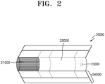
- FIG. 2 is a diagram showing an example of a cigarette.
- the cigarette 20000 includes a tobacco rod 21000 and a filter rod 22000.
- the first portion 21000 described above referring to FIG. 1 may include the tobacco rod 210000, and the second portion 22000 may include the filter rod 22000.
- the filter rod 22000 is shown as one segment in FIG. 2 , the filter rod is not limited thereto.
- the filter rod 22000 can be formed as a plurality of segments.
- the filter rod 22000 may include a first segment for cooling aerosol and a second segment for filtering some elements included in aerosol.
- the filter rod 22000 may further include at least one segment performing different function as desired.
- the cigarette 20000 may be packaged by at least one wrapper 24000.
- the wrapper 24000 may include at least one hole through which the outside air is introduced or inner gas is discharged.
- the cigarette 20000 may be packaged by one wrapper 24000.
- the cigarette 20000 may be packaged in an overlapped manner by at least two or more wrappers 24000.
- the cigarette 21000 may be packaged by the first wrapper and the filter rod 22000 may be packaged by the second wrapper. Additionally, the tobacco rod 21000 and filter rod 22000 are connected after being packaged by separate wrappers, and then whole part of the cigarette 20000 can be packaged again by a third wrapper.
- each segment can be packaged by a separate wrapper. Also, whole part of the cigarette 2000 formed by connected segments, which are packaged by separate wrappers, can be packaged again by another wrapper.
- the tobacco rod 21000 may include an aerosol generating material.
- the aerosol generating material may include at least one of glycerin, propylene glycol, ethylene glycol, dipropylene glycol, diethylene glycol, triethylene glycol, tetraethylene glycol, and oleyl alcohol, but not limited thereto.
- the tobacco rod 21000 may include other additive materials like a flavoring agent, a wetting agent, and/or organic acid.
- flavoring liquid like menthol or wetting material can be added into the tobacco rod 21000 by being sprayed onto the tobacco rod 21000.
- the tobacco rod 21000 can be manufactured by various methods.
- the tobacco rod 21000 can be formed by using a sheet, or a strand.
- the tobacco rod 21000 can be formed by using tobacco leaves cut from tobacco sheet.
- the tobacco rod 21000 can be surrounded by a thermal conductive material.
- a thermal conductive material may include metal foil like aluminum foil, but not limited thereto.
- the thermal conductive material surrounding the tobacco rod 21000 may increase thermal conductivity by evenly dispersing heat which is conducted to tobacco rod 21000, and therefore increase taste of tobacco.
- the thermal conductive material surrounding the tobacco rod 21000 may function as a susceptor being heated by an inductive heating type heater.
- the tobacco rod 21000 may further include an additional susceptor in addition to the thermal conductive material surrounding the outside of tobacco rod 21000.
- the filter rod 22000 may be a cellulose acetate filter. Meanwhile, the shape of the filter rod 22000 is not limited to a specific shape.
- the filter rod 22000 can be a cylindrical shape type rod or a tube type rod with a hollow cavity therein. Also, the filter rod 22000 can be a recess type rod. If the filter rod 22000 is made of a plurality of segments, at least one of the plurality of segments may have a different shape than others.
- the filter rod 22000 can be formed to generate flavor.
- flavoring liquid can be sprayed on the filter rod 22000, or a separate fiber coated with flavoring liquid can be inserted into the inside of the filter rod 22000.
- the filter rod 22000 can include at least of one capsule 23000.
- the capsule 23000 can generate a flavor or generate aerosol.
- the capsule 23000 may have a configuration in which a content liquid containing a flavoring material is wrapped with a film.
- the capsule 23000 may have a spherical or cylindrical shape.
- the cooling segment can be made from polymer or bio-degradable polymer.
- the cooling segment may be formed by polylactic acid, but not limited thereto. Otherwise, the cooling segment may be made of a cellulose acetate filter having a plurality of holes. But, the cooling segment is not limited to the above described example, and any configuration capable of providing a cooling function can be used.
- FIG. 3 is a perspective view of a heater assembly 70 according to an exemplary embodiment
- FIG. 4 is an exploded perspective view schematically illustrating a coupling relationship of components of the heater assembly 70 according to the exemplary embodiment shown in FIG. 3 .
- the heater assembly 70 may be inserted into a cigarette 7.
- the heater assembly 70 may include a heater 10 that heats the cigarette 7 when electricity is applied from the outside, and a first cover 20 and a second cover 30 which support the heater 10.
- the heater 10 may have a cylindrical shape or a rod shape extending in a longitudinal direction of the cigarette 7 to correspond to at least a part of the length of the cigarette 7.
- the heater 10 may have a diameter that is less than a diameter of the cigarette 7.
- a length of the heater 10 in an axial direction (where 'axial direction' means a longitudinal direction in which the central axis of the heater 10 extends) may be less than the length of the cigarette 7.
- a shape of the heater 10 is not limited by the exemplary embodiments represented in the drawings, and the shape of the heater 10 may be variously modified.
- the diameter of the heater 10 may be modified to be greater or less than that shown in FIG. 3 and may be manufactured in the shape of a needle.
- One end 11 of the heater 10 may have a pointy shape, and thus, the one end 11 of the heater 10 may be easily inserted into the cigarette 7.
- a wire 15 for supplying electricity to the heater 10 is connected to the heater 10.
- the wire 15 may be electrically connected to an outer surface of the heater 10 by, for example, a welding process, such as soldering or ultrasonic welding.
- the first cover 20 and the second cover 30 are coupled to the outside of the heater 10.
- the first cover 20 and the second cover 30 may be made of, for example, a heat resistant polymer material, a metal material, or a metal material or an alloy material coated with the heat resistant polymer material on a surface thereof.
- the first cover 20 is coupled to the heater 10 to maintain a position with respect to the heater 10.
- One surface 20f facing toward the one end 11 of the heater 10 of the first cover 20 extends outward from the heater 10.
- the one surface 20f of the first cover 20 may be disposed facing toward an end portion of the cigarette 7 into which the one end 11 of the heater 10 is inserted and may support the end portion of the cigarette 7.
- FIG. 5 is a perspective view showing some components inside of the heater assembly 70 according to the exemplary embodiment shown in FIG. 3 .
- FIG. 6 is a cross-sectional view showing a transverse section of a part of the heater assembly 70 according to the exemplary embodiment shown in FIG. 3 .
- FIG. 7 is a cross-sectional view showing an aerosol generation device including the heater assembly 70 according to the exemplary embodiment shown in FIG. 3 .
- the second cover 30 is coupled to the other end 12 of the heater 10.
- the second cover 30 may support the other end 12 of the heater 10 and may also support the first cover 20.
- the first cover 20 is first coupled to the heater 10 such that the first cover 20 maintains a position with respect to the heater 10.
- the second cover 30 is coupled to the other end 12 of the heater 10 and simultaneously, the second cover 30 is also coupled to the first cover 20.
- the second cover 30 also stably maintains a position with respect to the heater 10.
- the second cover 30 When the second cover 30 is coupled to the other end 12 of the heater 10, the second cover 30 may support the other surface 20r of the first cover 20 facing toward the other end 12 of the heater 10.
- the first cover 20 includes a flange 22 fixed to an outer surface of the heater 10 and protruding outward from the outer surface of the heater 10, and also includes an outer cover 21 disposed closer to the one end 11 of the heater 10 than the flange 22.
- the outer cover 21 may form the one surface 20f of the first cover 20, contacting and supporting at least a part of an outer surface 22s of the flange 22.
- the other surface 20r of the first cover 20 supported by the second cover 30 may be formed by a lower surface of the flange 22.
- the outer cover 21 of the first cover 20 includes a coupling hole 21h through which the one end 11 of the heater 10 passes.
- the first cover 20 includes a mounting plate 21y extending in a circumferential direction with respect to the heater 10, that is, with respect to the coupling hole 21h, so as to function as a support structure for coupling with the second cover 30.
- the flange 22 includes a through hole 22h through which the one end 11 of the heater 10 passes.
- the through hole 22h is directly coupled to an outer surface of the heater 10.
- the flange 22 may be made of a material having heat resistance and durability, such as alumina, ceramic, Teflon, and heat resistant plastic.
- the heater 10 When combining the flange 22 and the heater 10, the heater 10 may be first inserted into the through hole 22h of the flange 22 to set the position of the flange 22 with respect to the heater 10, and then ceramic bond may be injected into the through hole 22h of the flange 22 to temporarily fix the flange 22 and the heater 10. Thereafter, an assembly of the flange 22 and the heater 10 may be placed in a sintering furnace to apply heat such that the flange 22 and the heater 10 may be completely fixed.
- the exemplary embodiment is not limited by the coupling method of the flange 22 and the heater 10 described above, and the flange 22 and the heater 10 may be coupled using various methods.
- a screw coupling structure may be applied between the flange 22 and the heater 10
- a one-touch fastening structure such as a bayonet mount may be applied between the flange 22 and the heater 10.
- the flange 22 and the heater 10 may be joined using an adhesive, or the flange 22 may be provided to the outside of the heater 10 by applying an insert injection process according to a material of the flange 22.
- the first cover 20 includes an inner wall surface 21w extending along the outer surface 22s of the flange 22 to surround the outer surface 22s of the flange 22 coupled to the heater 10.
- the inner wall surface 21w is provided spaced apart by a predetermined gap from the outer surface 22s of the flange 22.
- the first cover 20 includes an inner protrusion 21p that protrudes from the inner wall surface 21w and contacts the outer surface 22s of the flange 22 to support the outer surface 22s.
- a plurality of inner protrusions 21p of the first cover 20 may be disposed to be spaced apart along the outer surface 22s of the flange 22.
- cross-sectional shapes of the flange 22 and the inner wall surface 21w in a transverse direction are substantially square shapes, but the exemplary embodiment is not limited by the shapes of the flange 22 and the inner wall surface 21w.
- the flange 22 may have a circular, elliptical, or polygonal cross-sectional shape, and the cross-sectional shape of the inner wall surface 21w of the first cover 20 may also be modified to correspond to the cross-sectional shape of the flange 22.
- the second cover 30 also extends in a circumferential direction in accordance with the first cover 20.
- the second cover 30 includes a mounting hole 30h into which the other end 12 of the heater 10 is inserted, and also includes a contact protrusion 37 protruding from the outside of the mounting hole 30h in a direction toward the flange 22 (i.e., in a direction toward the one end 11 of the heater 10).
- the contact protrusion 37 may directly contact the other surface 20r of the flange 22 toward the second cover 30 to stably support the flange 22 of the first cover 20.
- a plurality of contact protrusions 37 of the second cover 30 may be arranged to be spaced apart in the circumferential direction with respect to the mounting hole 30h.
- the number, installation positions or shapes of the contact protrusions 37 are not limited by the configuration of the exemplary embodiment shown in FIG. 4 , and the number and installation positions and shapes of the contact protrusions 37 may be variously modified.
- the first cover 20 and the second cover 30 may be coupled to each other on the outside of the contact protrusion 37.
- the second cover 30 includes an outer protrusion 38 that protrudes from the outside of the contact protrusion 37 toward the first cover 20.
- the mounting plate 21y of the first cover 20 extends in the circumferential direction with respect to the heater 10, and the outer protrusion 38 of the second cover 30 may also extend in the circumferential direction in accordance with the shape of the first cover 20.
- the first cover 20 and the second cover 30 may be coupled to each other by a bolt 50, which is an example of fastening means.
- the bolt 50 passes through a bolt through hole 51 formed in the second cover 30 and then is screwed into a screw hole (not shown) formed in the first cover 20 such that a coupling state of the first cover 20 and the second cover 30 may be stably maintained.
- a method of coupling the first cover 20 and the second cover 30 to each other is not limited only to a fastening method by the bolt 50 described in the embodiment.
- a different form of fastening means such as a rivet or a pin may be used.
- a bonding method using an adhesive may be used.
- a welding method using ultrasonic waves or heat may be used.
- a configuration such as protrusions, hooks, clips, coupling grooves, etc. may be applied to both sides of the first cover 20 and the second cover 30.
- screw surfaces corresponding to each other may be provided on both sides of the first cover 20 and the second cover 30.
- a one-touch fastening structure such as a bayonet mount may be applied, and thus, the configuration that the first cover 20 and the second cover 30 are coupled to each other may be implemented.
- the outer protrusion 38 and the mounting plate 21y may be coupled to each other and thus the first cover 20 and the second cover 30 may be fixed to each other.
- the second cover 30 when the first cover 20 and the second cover 30 are coupled to the heater 10, the second cover 30 stably supports the other surface 20r of the first cover 20 while the first cover 20 supports the heater 10 and the second cover 30 also supports the heater 10.
- a coupling interaction between the heater 10, the first cover 20, and the second cover 30 is performed in a cooperative manner. Therefore, in a state where the heater 10, the first cover 20, and the second cover 30 are coupled to each other, relative movement (shaking and floating) of the heater 10 with respect to the first cover 20 and the second cover 30 does not occur.
- the aerosol generation device includes a case 80 capable of accommodating the cigarette 7 and the heater assembly 70 disposed in the case 80 to heat the cigarette 7.
- the case 80 constitutes an outer appearance of the aerosol generation device, and accommodates and protects various components in a space formed therein.
- the case 80 includes a cigarette insertion hole having a hollow cylindrical shape and open to the outside at a front end thereof such that the cigarette 7 may be inserted.
- the case 80 may be made of a plastic material that does not conduct electricity and heat, or a metallic material coated with a plastic material on a surface thereof.
- the case 80 has the cylindrical shape having a circular cross-section, but the exemplary embodiment is not limited by a configuration of the case 80.
- the case 80 may have a cylindrical shape having a polygonal cross-section such as a quadrangle.
- the case 80 has a passage 81 for accommodating the cigarette 7.
- the heater assembly 70 that heats the cigarette 7 is coupled to the case 80.
- the one end 11 of the heater 10 of the heater assembly 70 is disposed inside of the passage 81 of the case 80, and when the cigarette 7 is accommodated in the case 80, the one end 11 of the heater 10 is inserted into a bottom surface of an end portion of the cigarette 7.
- the other end 12 of the heater 10 is electrically connected to a battery 90 disposed at the rear of the case 80 through the wire 15.
- the second cover 30 includes a wire hole 30w through which the wire 15 passes. One end of the wire 15 is electrically connected to the heater 10, and the other end of the wire 15 is electrically connected to the battery 90 through the wire hole 30w of the second cover 30.
- a base 85 surrounding the battery 90 is connected to the rear of the case 80.
- the cigarette 7 When a user of the aerosol generation device mounts the cigarette 7 to the case 80, the cigarette 7 is inserted into the passage 81 of the case 80 and moves along the passage 81. When the end portion of the cigarette reaches the one surface 20f of the first cover 20 of the heater assembly 70, a user's hand holding the cigarette 7 may sense the end portion of the cigarette 7 touching the one surface 20f of the first cover 20. Therefore, by simply pushing the cigarette 7 into the passage 81, the user may easily mount the cigarette 7 to the aerosol generation device.
- the first cover 20 and the second cover 30 firmly maintain their positions with respect to the heater 10 such that the first cover 20 and the second cover 30 do not move with respect to the heater 10 in a state of being coupled to the outside of the heater 10.
- the first cover 20 and the second cover 30 are fixed to the inside of the case 80, and thus, a position and a mounting state of the heater assembly 70 mounted inside of the case 80 may be stably maintained.
- an operation of inserting the one end 11 of the heater 10 into the cigarette 7 when the cigarette 7 is mounted to the case 80 and an operation of removing the cigarette 7 from the one end 11 of the heater 10 when the cigarette 7 is separated from the case 80 are repeated.
- the first cover 20 and the second cover 30 firmly support the heater 10, and thus, a state where the heater assembly 70 is mounted inside of the case 80 of the aerosol generation device is stably maintained. Therefore, defects due to repetitive use such as a poor coupling state of the heater assembly 70 or a disconnection of the wire 15 for supplying electricity to the heater 10 is disconnected, etc. may be prevented.
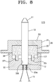
- FIG. 8 is a longitudinal cross-sectional view of a heater assembly 170 according to an exemplary embodiment.
- the heater assembly 170 may include the heater 10 to be inserted into a cigarette to generate heat when electricity is applied from the outside to heat the cigarette.
- the heater assembly 170 may include the first cover 20 that is coupled to the heater 10 to maintain a position with respect to the heater 10.
- the first cover 20 may have the one surface 20f near the one end 11 of the heater 10, which extends outward from the heater 10.
- the heater assembly 170 may include the second cover 30 that is coupled to the other end 12 of the heater 10 and supports the other surface 20r of the first cover 20 facing toward the other end 12 of the heater 10.
- the first cover 20 includes a flange 22 fixed to an outer surface of the heater 10 and protruding outward from the outer surface of the heater 10 and an outer cover 21 disposed at a position closer to the one end 11 of the heater 10 than a position of the flange 22 to form the one surface 20f of the first cover 20 and contacting and supporting an outer surface of the flange 22.
- the flange 22 includes a contact protrusion 127 protruding toward the second cover 30.
- the contact protrusion 127 forms at least a part of the other surface 20r from the first cover 20 toward the other end 12 of the heater 10.
- the second cover 30 may include a receiving groove 37h receiving the other surface 20r of the contact protrusion 127 to support the other surface 20r of the contact protrusion 127.
- a plurality of contact protrusions 127 may be disposed to be spaced apart from each other in a circumferential direction with respect to the heater 10.
- a plurality of receiving grooves 37h of the second cover 30 that receive the other surface 20r of the contact protrusion 127 may be also disposed to be spaced apart from each other in the circumferential direction with respect to the heater 10 in correspondence to the number of contact protrusions 127.
- the exemplary embodiment is not limited by configurations of the contact protrusion 127 of the flange 22 and the receiving groove 37h of the second cover 30, and the contact protrusion 127 and the receiving groove 37h may be variously modified.
- the contact protrusion 127 may extend in some sections of the circumferential direction with respect to the heater 10 to have a circular ring shape extending in the circumferential direction with respect to the heater 10 or an arc shape with respect to the heater 10.
- the receiving groove 37h of the second cover 30 may also have the circular ring shape or the arc shape.
- the second cover 30 when the first cover 20 and the second cover 30 are coupled to the heater 10, the second cover 30 stably supports the other surface 20r formed by the contact protrusion 127 protruding toward the second cover 30 in the flange 22 of the first cover 20 while the first cover 20 supports the heater 10 and the second cover 30 also supports the heater 10.
- coupling interactions between the heater 10, the first cover 20, and the second cover 30 may be performed in a cooperative manner. Therefore, in a state where the heater 10, the first cover 20, and the second cover 30 are coupled to each other, relative movement (shaking and floating) of the heater 10 with respect to the first cover 20 and the second cover 30 does not occur.
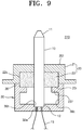
- FIG. 9 is a longitudinal cross-sectional view of a heater assembly 270 according to an exemplary embodiment.
- the heater assembly 270 may include the heater 10 that may be inserted into a cigarette and may generate heat when electricity is applied from the outside to heat the cigarette.
- the heater assembly 270 may include the first cover 20 coupled to the heater 10 and maintains a position with respect to the heater 10.
- the first cover 20 may have the one surface 20f facing toward the one end 11 of the heater 10 and extending outward from the heater 10.
- the heater assembly 270 may include the second cover 30 coupled to the other end 12 of the heater 10 and support the other surface 20r of the first cover 20 facing toward the other end 12 of the heater 10.
- the first cover 20 includes a flange 22 fixed to an outer surface of the heater 10 and protruding outward from the outer surface of the heater 10.
- the first cover 20 includes an outer cover 21 which is disposed closer to the one end 11 of the heater 10 than the flange 22 to form the one surface 20f of the first cover 20, and contacts and supports the outer surface 22s of the flange 22.
- the other surface 20r of the first cover 20 supported by the second cover 30 is formed by a lower surface of the flange 22.
- the second cover 30 When the second cover 30 is coupled to the other end 12 of the heater 10, the second cover 30 may support the other surface 20r of the first cover 20 facing toward the other end 12 of the heater 10.
- an installation position of a contact protrusion 237 of the second cover 30 for supporting the other surface 20r of the first cover 20 is modified.
- the second cover 30 includes the mounting hole 30h into which the other end 12 of the heater 10 is inserted, a receiving chamber 30c extending outward from the heater 10 so as to be spaced outward from the outer surface of the heater 10 and surrounding the heater 10, and a contact protrusion 237 protruding from an inner surface of the receiving chamber 30c toward the outer surface of the heater 10 and contacting the other surface 20r of the flange 22.
- a plurality of contact protrusions 237 may be installed to be spaced apart along the outer surface 22s of the flange 22.
- the exemplary embodiment is not limited by a structure of the contact protrusion 237, and thus, the structure of the contact protrusion 237 may be variously modified.
- the contact protrusion 237 may be formed to extend along the other surface 20r of the flange 22.
- the contact protrusion 237 may have a circular or elliptical shape extending in a circumferential direction along an extension direction of the outer surface 22s of the flange 22, or an arc shape extending in some sections of the circumferential direction of the extension direction of the outer surface 22s of the flange 22.
- the contact protrusion 237 may also have a polygonal shape extending along the other surface 20r of the flange 22.
- the contact protrusion 237 protruding toward the heater 10 from the inner surface of the receiving chamber 30c of the second cover 30 stably supports the other surface 20r of the first cover 20 formed on the flange 22 while the first cover 20 supports the heater 10 and the second cover 30 also supports the heater 10.
- a coupling interaction between the heater 10, the first cover 20, and the second cover 30 is performed in a cooperative manner. Therefore, in a state where the heater 10, the first cover 20, and the second cover 30 are coupled to each other, relative movement (shake and floating) of the heater 10 with respect to the first cover 20 and the second cover 30 does not occur.
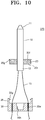
- FIG. 10 is an exploded perspective view schematically illustrating a coupling relationship of components of a heater assembly 370 according to another embodiment.
- FIG. 11 is a cross-sectional view of the heater assembly 370 according to the exemplary embodiment shown in FIG. 10 .
- the heater assembly 370 may include the heater 10 that may be inserted into a cigarette and generate heat when electricity is applied from the outside to heat the cigarette.
- the heater assembly 370 may include the first cover 20 that may be coupled to the heater 10 and maintain a position with respect to the heater 10.
- the first cover 20 may have the one surface 20f facing toward the one end 11 of the heater 10 extending outward from the heater 10.
- the heater assembly 370 may include the second cover 30 that may be coupled to the other end 12 of the heater 10 and support the other surface 20r of the first cover 20 facing toward the other end 12 of the heater 10.
- a configuration of the first cover 20 is modified.
- the first cover 20 is integrally fixed to the outside of the heater 10 by insert injection molding. That is, after the heater 10 is first made of a metal or alloy material, the heater 10 is placed in a previously prepared mold, and then a molten heat resistant plastic (resin) solution is injected into the mold and then cooled, and thus, the first cover 20 is installed in the outside of the heater 10. According to such an insert injection molding, the heater 10 and the first cover 20 may be integrated into one body and completely fixed to each other.
- FIG. 10 illustrates an example of an operation of assembling the second cover 30 with an assembly of the heater 10 and the first cover 20 after the heater 10 and the first cover 20 are integrated by insert injection molding.
- the second cover 30 includes the mounting hole 30h into which the other end 12 of the heater 10 is inserted.
- the second cover 30 is coupled to the first cover 20, and thus, the second cover 30 may firmly support the other surface 20r of the first cover 20.
- a fastening structure using a hook and a coupling groove is applied between the first cover 20 and the second cover 30.
- the first cover 20 includes a coupling groove 20g in an outer surface thereof in a radial direction.
- the second cover 30 includes an outer protrusion 38 protruding from an outer side of the mounting hole 30h toward the first cover 20, and the outer protrusion 38 includes a hook 30g protruding inward so as to be inserted into the coupling groove 20g of the first cover 20.
- the second cover 30 includes a wire hole 30w through which the wire 15 passes.
- a coupling operation of the second cover 30 and the first cover 20 is performed together. That is, as the second cover 30 moves toward the first cover 20, the hook 30g of the outer protrusion 38 of the second cover 30 is slightly open and then inserted into the coupling groove 20g of the first cover 20, and thus, the hook 30g and the coupling groove 20g are completely coupled.
- the hook 30g and the coupling groove 20g are coupled to each other and stably maintain the coupling a state.
- the second cover 30 may firmly support the other surface 20r of the first cover 20 facing toward the other end 12 of the heater 10.
- the first cover 20 and the heater 10 are completely fixed to each other to form an integral body by insert injection molding.
- the second cover 30 may firmly support the other surface 20r of the first cover 20 and simultaneously support the other end 12 of the heater 10.
- a coupling interaction between the heater 10, the first cover 20, and the second cover 30 is performed in a cooperative manner, and thus, in a state where the heater 10, the first cover 20, and the second cover 30 are coupled to each other, relative movement (shaking and floating) of the heater 10 with respect to the first cover 20 and the second cover 30 may be prevented.
- the tight coupling of the first cover 20 and the heater 10 by insert injection molding leaves no gap between the first cover 20 and the heater 10, and thus, a good sealing effect may be obtained. That is, because it is difficult for a material generated during a process of generating aerosol by heating a cigarette using the heater 10 inserted into the cigarette or impurities introduced into an aerosol generation device from the outside to be introduced through a coupling part between the heater 10 and the first cover 20, the sealing effect of preventing an external material from being introduced toward the other end 12 of the heater 10 is improved.
- a dimension precision between components is improved as compared to a method of heating the heater 10 and the first cover 20 in a sintering furnace. That is, after the first cover 20 and the heater 10 are integrally formed by insert injection molding, deformation of the first cover 20 does not occur in post-processing for manufacturing the heater assembly 370 and a shape of the first cover 20 is maintained. Therefore, in a process of assembling the first cover 20 and the second cover 30 or in a process of coupling the heater assembly 370 with the aerosol generation device or with other components, dimensions between the components precisely fit according to the initial design, and thus, a perfect product design may be implemented.
- the first cover 20 and the second cover 30 firmly support the heater 10, and a state where the heater assembly 370 is mounted inside of the aerosol generation device is stably maintained. Therefore, even when an operation of inserting the heater 10 into a cigarette and separating the cigarette from the heater 10 is repeatedly performed, because a coupling state of the components of the heater assembly 370 is maintained to be firm, a phenomenon of shaking between the components hardly occurs, and thus, defects such as disconnection of the wire 15 for supplying electricity to the heater 10 hardly occur.
Landscapes
- Health & Medical Sciences (AREA)
- Engineering & Computer Science (AREA)
- Chemical & Material Sciences (AREA)
- Life Sciences & Earth Sciences (AREA)
- Animal Behavior & Ethology (AREA)
- Veterinary Medicine (AREA)
- Public Health (AREA)
- General Health & Medical Sciences (AREA)
- Anesthesiology (AREA)
- Biomedical Technology (AREA)
- Heart & Thoracic Surgery (AREA)
- Hematology (AREA)
- General Chemical & Material Sciences (AREA)
- Pulmonology (AREA)
- Bioinformatics & Cheminformatics (AREA)
- Chemical Kinetics & Catalysis (AREA)
- Materials Engineering (AREA)
- Resistance Heating (AREA)
Abstract
Description
- The present disclosure relates to a heater assembly and an aerosol generation device including the same, and more particularly, to a heater assembly with enhanced durability achieved by maintaining a firm assembling state, and an aerosol generation device including the same.
- Recently, there is a growing demand for alternative methods for resolving problems of a common cigarette. For example, there is a growing demand for a method of generating aerosol by heating an aerosol generating material in a cigarette instead of burning the cigarette to generate aerosol. Therefore, research into heating-type cigarettes or heating-type aerosol generation devices is being actively carried out.
- An aerosol generation device that heats a cigarette to generate aerosol uses a heater assembly that generates heat by electricity. In the heater assembly that heats a cigarette in a state of being inserted into the cigarette, a heater may be shaken due to a loosened coupling state of components in a process of repeatedly performing an operation of inserting and separating the heater assembly into and from the cigarette. In addition, due to manufacturing tolerances of components coupled to the heater so as to support the heater, a position of the heater disposed inside of the aerosol generation device may not be stably maintained, and the heater and the components may be shaken when the cigarette is mounted or when the cigarette is separated. As such, when the assembling state of the heater assembly is defective, external impurities may be introduced into the aerosol generation device through the heater assembly, which may degrade the performance of an electronic component.
- Exemplary embodiments provide a heater assembly with enhanced durability and sealing performance obtained by a firm assembling state and an aerosol generation device including the same.
- Exemplary embodiments also provide a heater assembly in which components for supporting a heater are firmly coupled to each other such that an occurrence of shaking of the heater is minimized and an aerosol generation device including the same.
- According to an aspect of the present disclosure, a heater extending to correspond to at least a part of a length of a cigarette and comprising one end to be inserted into the cigarette and configured to generate heat when electricity is applied; a first cover coupled to the heater to maintain a position with respect to the heater and comprising one surface that faces toward the end of the heater and extends outward from the heater; and a second cover coupled to another end of the heater and supporting another surface of the first cover facing toward the other end of the heater.
- The first cover may include a flange fixed to an outer surface of the heater and protruding outward from the outer surface of the heater; and an outer cover disposed closer to the one end of the heater than the flange to form the one surface, and configured to contact and support at least a part of an outer surface of the flange, and wherein the other surface of the first cover supported by the second cover is formed by the flange.
- The outer cover may further include an inner protrusion protruding from an inner side of the outer cover and contacting the outer surface of the flange.
- The second cover may include a mounting hole into which the other end of the heater is inserted; and a contact protrusion protruding from outside of the mounting hole toward the flange to contact the other surface of the flange facing toward the second cover.
- A plurality of contact protrusions may be arranged to be spaced apart from each other in a circumferential direction with respect to the heater.
- The contact protrusion may extend in a circumferential direction with respect to the heater.
- The first cover and the second cover may be coupled to each other at outside of the contact protrusion.
- The second cover may include an outer protrusion protruding from the outside of the contact protrusion toward the first cover and coupled to the first cover, and the first cover and the outer protrusion of the second cover extend in a circumferential direction with respect to the heater.
- The flange may include a contact protrusion protruding toward the second cover and forming the other surface of the first cover supported by the second cover, and the second cover comprises a receiving groove receiving and supporting the other surface formed by the contact protrusion.
- The second cover may include a mounting hole into which the other end of the heater is inserted; a receiving chamber extending outward from the heater and spaced apart from the outer surface of the heater to surround the heater; and a contact protrusion protruding from an inner surface of the receiving chamber toward the heater and contacting the other surface formed by the flange that faces toward the second cover.
- A plurality of contact protrusions may be arranged to be spaced apart from each other along an outer surface of the flange.
- The contact protrusion may extend along at least a part of an outer surface of the flange.
- A wire for supplying electricity to the heater may be connected to the heater and the second cover may include a wire hole through which the wire passes.
- The first cover may be integrally fixed to the outside of the heater by insert injection molding, the second cover may include a mounting hole into which the other end of the heater is inserted, and when the other end of the heater is inserted into the mounting hole, the second cover may be coupled to the first cover and supports the other surface of the first cover.
- According to another aspect of the present disclosure, an aerosol generation device includes a heater assembly relating to the exemplary embodiments described above, a hollow case including a cigarette insertion hole open to outside and configured to receive the cigarette; and a battery disposed in the case to supply electricity to the heater assembly.
- In the heater assembly and the aerosol generation device including the same according to exemplary embodiments as described above, a second cover stably supports the other surface of a first cover that is coupled to a heater and maintains a position with respect to the heater and simultaneously the second cover supports the other end of the heater. As such, because a coupling interaction between the heater, the first cover, and the second cover is performed in a cooperative manner, a position of the heater disposed inside of the aerosol generation device may be firmly supported, and thus, relative movement (shaking and floating) of components of the heater assembly hardly occurs.
- In addition, because the first cover and the second cover firmly support the heater, a state in which the heater assembly is mounted inside of the aerosol generation device is stably maintained, and thus, a defect due to repetitive use such as a poor coupling state of the heater assembly or disconnection of a wire for supplying electricity, etc. hardly occurs.
- In addition, in the heater assembly in which the first cover and the heater are integrally formed by insert injection molding, the first cover and the heater are tightly coupled to each other, so no gap occurs in a coupling part of the first cover and the heater, which results in a perfect sealing effect.
- Also, after the first cover and the heater are integrally formed by insert injection molding, because deformation of the first cover does not occur in post-processing for the heater assembly, in a process of coupling the heater assembly with other components, dimensions between the components precisely fit according to the initial design, and thus, a perfect product design may be implemented.
-
-
FIG. 1 is a diagram showing an example in which a cigarette is inserted into an aerosol generation device. -
FIG. 2 is a diagram showing an example of a cigarette. -
FIG. 3 is a perspective view of a heater assembly according to an embodiment. -
FIG. 4 is an exploded perspective view schematically illustrating a coupling relationship of components of the heater assembly according to the exemplary embodiment shown inFIG. 3 . -
FIG. 5 is a perspective view showing some components inside of the heater assembly according to the exemplary embodiment shown inFIG. 3 . -
FIG. 6 is a cross-sectional view showing a transverse section of a part of the heater assembly according to the exemplary embodiment shown inFIG. 3 . -
FIG. 7 is a cross-sectional view showing an aerosol generation device including the heater assembly according to the exemplary embodiment shown inFIG. 3 . -
FIG. 8 is a longitudinal cross-sectional view of a heater assembly according to another embodiment. -
FIG. 9 is a longitudinal cross-sectional view of a heater assembly according to another embodiment. -
FIG. 10 is an exploded perspective view schematically illustrating a coupling relationship of components of a heater assembly according to another embodiment. -
FIG. 11 is a cross-sectional view of the heater assembly according to the exemplary embodiment shown inFIG. 10 . - With respect to the terms in the various exemplary embodiments of the present disclosure, the general terms which are currently and widely used are selected in consideration of functions of structural elements in the various exemplary embodiments of the present disclosure. However, meanings of the terms may be changed according to intention, a judicial precedent, appearance of a new technology, and the like. In addition, in certain cases, a term which is not commonly used may be selected. In such a case, the meaning of the term will be described in detail at the corresponding part in the description of the present disclosure. Therefore, the terms used in the various exemplary embodiments of the present disclosure should be defined based on the meanings of the terms and the descriptions provided herein.
- In addition, unless explicitly described to the contrary, the word "comprise" and variations such as "comprises" or "comprising" will be understood to imply the inclusion of stated elements but not the exclusion of any other elements. In addition, the terms "-er", "-or", and "module" described in the specification mean units for processing at least one function and operation and can be implemented by hardware components or software components and combinations thereof.
- Hereinafter, exemplary embodiments of the present disclosure will be described in detail with reference to the accompanying drawings. The disclosure may, however, be embodied in many different forms and should not be construed as limited to the exemplary embodiments set forth herein.
- Hereinafter, exemplary embodiments of the present disclosure will be described in detail with reference to the drawings.
-
FIG. 1 is a diagram showing an example in which a cigarette is inserted into an aerosol generation device. - Referring to
FIG. 1 , theaerosol generation device 10000 includes abattery 11000, acontrol unit 12000, and aheater 13000. Also, theaerosol generation device 10000 is inserted into an inside space of thecigarette 20000. -
FIG. 1 only shows certain elements of theaerosol generation device 10000 which are related to a particular exemplary embodiment. Therefore, it will be understood by one of ordinary skill in the art that theaerosol generation device 10000 may further include additional general purpose elements in addition to elements shown inFIG. 1 . - Although
Fig. 1 shows that thebattery 11000,control unit 12000, andheater 13000 are arranged in line, the exemplary embodiments are not limited to this feature. In other words, arrangements of thebattery 11000,control unit 12000, and heater can be changed according to design plan of theaerosol generating device 10000. - When the
cigarette 20000 is inserted into theaerosol generating device 10000, theaerosol generating device 10000 heats theheater 13000. The temperature of an aerosol generating material in thecigarette 20000 is raised by theheated heater 13000, and thus aerosol is generated. The generated aerosol is delivered to a user through acigarette filter 22000 of thecigarette 20000. - However, as necessary, even when a
cigarette 20000 is not inserted into theaerosol generating device 10000, theaerosol generating device 10000 may heat theheater 13000. - The
battery 11000 supplies power used for theaerosol generating device 10000 to operate. For example, thebattery 11000 may supply power for heating theheater 13000 and supply power for operating thecontrol unit 12000. In addition, thebattery 11000 may supply power for operating a display, a sensor, a motor, and the like installed in theaerosol generating device 10000. - The
control unit 12000 may control the overall operation of theaerosol generating device 10000. Specifically, thecontrol unit 12000 may control not only operations of the battery 110 and theheater 13000, but also operations of other components included in theaerosol generating device 10000. Thecontrol unit 12000 may also check the status of each of the components of theaerosol generating device 10000 and determine whether theaerosol generating device 10000 is in an operable state. - The
control unit 12000 may include at least one processor. A processor may be implemented by an array of a plurality of logic gates or may be implemented by a combination of a general purpose microprocessor and a memory in which a program executable in the microprocessor is stored. It will be understood by one of ordinary skill in the art that the present disclosure may be implemented in other forms of hardware. - The
heater 13000 is heated by power supplied from thebattery 11000. For example, when a cigarette is inserted into theaerosol generating device 10000, theheater 13000 can be located inside the cigarette. Therefore, theheated heater 13000 may raise the temperature of an aerosol generating material in the cigarette. - The
heater 13000 may be an electrical resistive heater. For example, theheater 13000 may include an electrically conductive track, and theheater 13000 may be heated as electrical current flows through the electrically conductive track. But, theheater 13000 is not limited to the above example, and any heater structure being able to be heated to a desired temperature can be adapted. The desired temperature may be preset in theaerosol generating device 10000, or user may set up the desired temperature. - Meanwhile, as another example, the
heater 13000 can be an inductive heater. To be specific, theheater 13000 may include electrical conductive coil for heating by an inductive heating method, and the cigarette may include a susceptor that can be heated by an inductive heater. -
Fig. 1 shows that theheater 13000 is disposed to be inserted into the inside of thecigarette 20000, but the exemplary embodiments are not limited thereto. For example, theheater 13000 may include a pipe-shaped heating element, a plate-shaped heating element, a needle-shaped heating element, or a rod-shaped heating element. Theheater 13000 may heat the inside or outside of thecigarette 20000 based on the shape of the heating element. - Also, the
aerosol generating device 10000 may include a plurality ofheaters 13000. Here, the plurality ofheaters 13000 can be disposed to be inserted into inside of thecigarette 20000, or disposed outside of thecigarette 20000. Also, a part of the plurality ofheaters 13000 may be disposed to be inserted into inside of thecigarette 20000, and the rest of the plurality ofheaters 13000 may be disposed outside of thecigarette 20000. Also, the shape of the heater 130000 is not limited to the shape shown inFIG. 1 , and may be manufactured into various shapes. - Meanwhile, the
aerosol generating device 10000 may include additional general-purpose components other than thebattery 11000, thecontrol unit 12000, and theheater 13000. For example, theaerosol generating device 10000 may include a display capable of outputting visual information and/or a motor for outputting tactile information. Theaerosol generating device 10000 may also include at least one sensor (e.g., a puff detecting sensor, a temperature sensing sensor, a cigarette insertion detecting sensor, etc). - Also, the
aerosol generating device 10000 may be fabricated to have a structure in which the outside air may flow in/out even in the state where thecigarette 20000 is inserted. - Although now shown in
FIG. 1 , theaerosol generating device 10000 may form a part of the system along with an additional cradle. For example, the cradle may be used to charge thebattery 11000 of theaerosol generating device 10000. Also, theheater 13000 may be heated while the cradle and theaerosol generating device 10000 are connected. - The
cigarette 20000 may be similar to a general combustion-type cigarette. For example, thecigarette 20000 may include afirst portion 21000 containing an aerosol generating material and asecond portion 22000 including a filter and the like. Also, thecigarette 20000 may also include an aerosol generating material in thesecond portion 22000. For example, an aerosol generating material in the form of granules or capsules may be inserted into thesecond portion 22000. - The entire
first portion 21000 may be inserted into theaerosol generating device 10000 and thesecond portion 22000 may be exposed to the outside. Alternatively, only a portion of thefirst portion 21000 may be inserted into theaerosol generating device 10000 or the entirefirst portion 21000 and a portion of thesecond portion 22000 may be inserted into theaerosol generating device 10000. A user may inhale the aerosol while holding thesecond portion 22000 by his/her lips. At this time, the aerosol is generated from the outside air passing through thefirst portion 21000, and generated aerosol is delivered to a user's mouth by passing through thesecond portion 22000. - As an example, the outside air can be introduced through at least one air passage formed in the
aerosol generating device 10000. For example, opening and closing of the air passage formed in theaerosol generating device 10000 and/or a size of the air passage can be adjusted by user. Accordingly, the amount of smoke and a smoking impression may be adjusted by the user. As another example, the outside air may be introduced into inside of thecigarette 20000 through at least one hole formed in a surface of thecigarette 20000, - Hereinafter, an exemplary embodiment of the
cigarette 20000 will be explained referring toFIG. 2 . -
FIG. 2 is a diagram showing an example of a cigarette. - Referring to
FIG. 2 , thecigarette 20000 includes atobacco rod 21000 and afilter rod 22000. Thefirst portion 21000 described above referring toFIG. 1 may include the tobacco rod 210000, and thesecond portion 22000 may include thefilter rod 22000. - Although the
filter rod 22000 is shown as one segment inFIG. 2 , the filter rod is not limited thereto. In other words, thefilter rod 22000 can be formed as a plurality of segments. For example, thefilter rod 22000 may include a first segment for cooling aerosol and a second segment for filtering some elements included in aerosol. Also, thefilter rod 22000 may further include at least one segment performing different function as desired. - The
cigarette 20000 may be packaged by at least onewrapper 24000. Thewrapper 24000 may include at least one hole through which the outside air is introduced or inner gas is discharged. As an example, thecigarette 20000 may be packaged by onewrapper 24000. As another example, thecigarette 20000 may be packaged in an overlapped manner by at least two ormore wrappers 24000. For example, thecigarette 21000 may be packaged by the first wrapper and thefilter rod 22000 may be packaged by the second wrapper. Additionally, thetobacco rod 21000 andfilter rod 22000 are connected after being packaged by separate wrappers, and then whole part of thecigarette 20000 can be packaged again by a third wrapper. If thetobacco rod 21000 orfilter rod 22000 is made into a plurality of segments, each segment can be packaged by a separate wrapper. Also, whole part of the cigarette 2000 formed by connected segments, which are packaged by separate wrappers, can be packaged again by another wrapper. - The
tobacco rod 21000 may include an aerosol generating material. For example, the aerosol generating material may include at least one of glycerin, propylene glycol, ethylene glycol, dipropylene glycol, diethylene glycol, triethylene glycol, tetraethylene glycol, and oleyl alcohol, but not limited thereto. Also, thetobacco rod 21000 may include other additive materials like a flavoring agent, a wetting agent, and/or organic acid. Also, flavoring liquid like menthol or wetting material can be added into thetobacco rod 21000 by being sprayed onto thetobacco rod 21000. - The
tobacco rod 21000 can be manufactured by various methods. For example, thetobacco rod 21000 can be formed by using a sheet, or a strand. Also, thetobacco rod 21000 can be formed by using tobacco leaves cut from tobacco sheet. Also, thetobacco rod 21000 can be surrounded by a thermal conductive material. For example, a thermal conductive material may include metal foil like aluminum foil, but not limited thereto. As one example, the thermal conductive material surrounding thetobacco rod 21000 may increase thermal conductivity by evenly dispersing heat which is conducted totobacco rod 21000, and therefore increase taste of tobacco. Also, the thermal conductive material surrounding thetobacco rod 21000 may function as a susceptor being heated by an inductive heating type heater. In this case, although not shown in drawings, thetobacco rod 21000 may further include an additional susceptor in addition to the thermal conductive material surrounding the outside oftobacco rod 21000. - The
filter rod 22000 may be a cellulose acetate filter. Meanwhile, the shape of thefilter rod 22000 is not limited to a specific shape. For example, thefilter rod 22000 can be a cylindrical shape type rod or a tube type rod with a hollow cavity therein. Also, thefilter rod 22000 can be a recess type rod. If thefilter rod 22000 is made of a plurality of segments, at least one of the plurality of segments may have a different shape than others. - The
filter rod 22000 can be formed to generate flavor. For example, flavoring liquid can be sprayed on thefilter rod 22000, or a separate fiber coated with flavoring liquid can be inserted into the inside of thefilter rod 22000. - Also, the
filter rod 22000 can include at least of onecapsule 23000. Here, thecapsule 23000 can generate a flavor or generate aerosol. For example, thecapsule 23000 may have a configuration in which a content liquid containing a flavoring material is wrapped with a film. For example, thecapsule 23000 may have a spherical or cylindrical shape. - If the
filter rod 22000 includes a cooling segment for cooling aerosol, the cooling segment can be made from polymer or bio-degradable polymer. For example, the cooling segment may be formed by polylactic acid, but not limited thereto. Otherwise, the cooling segment may be made of a cellulose acetate filter having a plurality of holes. But, the cooling segment is not limited to the above described example, and any configuration capable of providing a cooling function can be used. -
FIG. 3 is a perspective view of aheater assembly 70 according to an exemplary embodiment, andFIG. 4 is an exploded perspective view schematically illustrating a coupling relationship of components of theheater assembly 70 according to the exemplary embodiment shown inFIG. 3 . - The
heater assembly 70 according to the exemplary embodiment shown inFIGS. 3 and4 may be inserted into acigarette 7. Theheater assembly 70 may include aheater 10 that heats thecigarette 7 when electricity is applied from the outside, and afirst cover 20 and asecond cover 30 which support theheater 10. - The
heater 10 may have a cylindrical shape or a rod shape extending in a longitudinal direction of thecigarette 7 to correspond to at least a part of the length of thecigarette 7. Theheater 10 may have a diameter that is less than a diameter of thecigarette 7. A length of theheater 10 in an axial direction (where 'axial direction' means a longitudinal direction in which the central axis of theheater 10 extends) may be less than the length of thecigarette 7. - A shape of the
heater 10 is not limited by the exemplary embodiments represented in the drawings, and the shape of theheater 10 may be variously modified. For example, the diameter of theheater 10 may be modified to be greater or less than that shown inFIG. 3 and may be manufactured in the shape of a needle. - One
end 11 of theheater 10 may have a pointy shape, and thus, the oneend 11 of theheater 10 may be easily inserted into thecigarette 7. In addition, awire 15 for supplying electricity to theheater 10 is connected to theheater 10. Thewire 15 may be electrically connected to an outer surface of theheater 10 by, for example, a welding process, such as soldering or ultrasonic welding. - The
first cover 20 and thesecond cover 30 are coupled to the outside of theheater 10. Thefirst cover 20 and thesecond cover 30 may be made of, for example, a heat resistant polymer material, a metal material, or a metal material or an alloy material coated with the heat resistant polymer material on a surface thereof. - The
first cover 20 is coupled to theheater 10 to maintain a position with respect to theheater 10. Onesurface 20f facing toward the oneend 11 of theheater 10 of thefirst cover 20 extends outward from theheater 10. - When the one
end 11 of theheater 10 is inserted into thecigarette 7, the onesurface 20f of thefirst cover 20 may be disposed facing toward an end portion of thecigarette 7 into which the oneend 11 of theheater 10 is inserted and may support the end portion of thecigarette 7. -
FIG. 5 is a perspective view showing some components inside of theheater assembly 70 according to the exemplary embodiment shown inFIG. 3 .FIG. 6 is a cross-sectional view showing a transverse section of a part of theheater assembly 70 according to the exemplary embodiment shown inFIG. 3 .FIG. 7 is a cross-sectional view showing an aerosol generation device including theheater assembly 70 according to the exemplary embodiment shown inFIG. 3 . - Referring to
FIGS. 5 and7 , thesecond cover 30 is coupled to theother end 12 of theheater 10. Thesecond cover 30 may support theother end 12 of theheater 10 and may also support thefirst cover 20. - In assembling the
heater assembly 70, thefirst cover 20 is first coupled to theheater 10 such that thefirst cover 20 maintains a position with respect to theheater 10. When thefirst cover 20 is first coupled to theheater 10 and then thesecond cover 30 is coupled to theheater 10, thesecond cover 30 is coupled to theother end 12 of theheater 10 and simultaneously, thesecond cover 30 is also coupled to thefirst cover 20. As such, thesecond cover 30 also stably maintains a position with respect to theheater 10. - When the
second cover 30 is coupled to theother end 12 of theheater 10, thesecond cover 30 may support theother surface 20r of thefirst cover 20 facing toward theother end 12 of theheater 10. - The
first cover 20 includes aflange 22 fixed to an outer surface of theheater 10 and protruding outward from the outer surface of theheater 10, and also includes anouter cover 21 disposed closer to the oneend 11 of theheater 10 than theflange 22. Theouter cover 21 may form the onesurface 20f of thefirst cover 20, contacting and supporting at least a part of anouter surface 22s of theflange 22. Theother surface 20r of thefirst cover 20 supported by thesecond cover 30 may be formed by a lower surface of theflange 22. - The
outer cover 21 of thefirst cover 20 includes acoupling hole 21h through which the oneend 11 of theheater 10 passes. In addition, thefirst cover 20 includes a mountingplate 21y extending in a circumferential direction with respect to theheater 10, that is, with respect to thecoupling hole 21h, so as to function as a support structure for coupling with thesecond cover 30. - The
flange 22 includes a throughhole 22h through which the oneend 11 of theheater 10 passes. The throughhole 22h is directly coupled to an outer surface of theheater 10. Theflange 22 may be made of a material having heat resistance and durability, such as alumina, ceramic, Teflon, and heat resistant plastic. - When combining the
flange 22 and theheater 10, theheater 10 may be first inserted into the throughhole 22h of theflange 22 to set the position of theflange 22 with respect to theheater 10, and then ceramic bond may be injected into the throughhole 22h of theflange 22 to temporarily fix theflange 22 and theheater 10. Thereafter, an assembly of theflange 22 and theheater 10 may be placed in a sintering furnace to apply heat such that theflange 22 and theheater 10 may be completely fixed. - The exemplary embodiment is not limited by the coupling method of the
flange 22 and theheater 10 described above, and theflange 22 and theheater 10 may be coupled using various methods. For example, a screw coupling structure may be applied between theflange 22 and theheater 10, or a one-touch fastening structure such as a bayonet mount may be applied between theflange 22 and theheater 10. Theflange 22 and theheater 10 may be joined using an adhesive, or theflange 22 may be provided to the outside of theheater 10 by applying an insert injection process according to a material of theflange 22. - Referring to
FIG. 6 , thefirst cover 20 includes aninner wall surface 21w extending along theouter surface 22s of theflange 22 to surround theouter surface 22s of theflange 22 coupled to theheater 10. Theinner wall surface 21w is provided spaced apart by a predetermined gap from theouter surface 22s of theflange 22. - The
first cover 20 includes aninner protrusion 21p that protrudes from theinner wall surface 21w and contacts theouter surface 22s of theflange 22 to support theouter surface 22s. A plurality ofinner protrusions 21p of thefirst cover 20 may be disposed to be spaced apart along theouter surface 22s of theflange 22. - In the exemplary embodiment shown in the drawing, cross-sectional shapes of the
flange 22 and theinner wall surface 21w in a transverse direction are substantially square shapes, but the exemplary embodiment is not limited by the shapes of theflange 22 and theinner wall surface 21w. For example, theflange 22 may have a circular, elliptical, or polygonal cross-sectional shape, and the cross-sectional shape of theinner wall surface 21w of thefirst cover 20 may also be modified to correspond to the cross-sectional shape of theflange 22. - The
second cover 30 also extends in a circumferential direction in accordance with thefirst cover 20. Thesecond cover 30 includes a mountinghole 30h into which theother end 12 of theheater 10 is inserted, and also includes acontact protrusion 37 protruding from the outside of the mountinghole 30h in a direction toward the flange 22 (i.e., in a direction toward the oneend 11 of the heater 10). Thecontact protrusion 37 may directly contact theother surface 20r of theflange 22 toward thesecond cover 30 to stably support theflange 22 of thefirst cover 20. - A plurality of
contact protrusions 37 of thesecond cover 30 may be arranged to be spaced apart in the circumferential direction with respect to the mountinghole 30h. The number, installation positions or shapes of thecontact protrusions 37 are not limited by the configuration of the exemplary embodiment shown inFIG. 4 , and the number and installation positions and shapes of thecontact protrusions 37 may be variously modified. - The
first cover 20 and thesecond cover 30 may be coupled to each other on the outside of thecontact protrusion 37. Thesecond cover 30 includes anouter protrusion 38 that protrudes from the outside of thecontact protrusion 37 toward thefirst cover 20. The mountingplate 21y of thefirst cover 20 extends in the circumferential direction with respect to theheater 10, and theouter protrusion 38 of thesecond cover 30 may also extend in the circumferential direction in accordance with the shape of thefirst cover 20. - Referring to
FIGS. 4 and5 , thefirst cover 20 and thesecond cover 30 may be coupled to each other by abolt 50, which is an example of fastening means. Thebolt 50 passes through a bolt throughhole 51 formed in thesecond cover 30 and then is screwed into a screw hole (not shown) formed in thefirst cover 20 such that a coupling state of thefirst cover 20 and thesecond cover 30 may be stably maintained. - A method of coupling the
first cover 20 and thesecond cover 30 to each other is not limited only to a fastening method by thebolt 50 described in the embodiment. For example, a different form of fastening means such as a rivet or a pin may be used. Also, a bonding method using an adhesive may be used. Also, a welding method using ultrasonic waves or heat may be used. Also, a configuration such as protrusions, hooks, clips, coupling grooves, etc. may be applied to both sides of thefirst cover 20 and thesecond cover 30. Also, screw surfaces corresponding to each other may be provided on both sides of thefirst cover 20 and thesecond cover 30. Also, a one-touch fastening structure such as a bayonet mount may be applied, and thus, the configuration that thefirst cover 20 and thesecond cover 30 are coupled to each other may be implemented. - Alternatively, the
outer protrusion 38 and the mountingplate 21y may be coupled to each other and thus thefirst cover 20 and thesecond cover 30 may be fixed to each other. - In the
heater assembly 70 having the above-described configuration, when thefirst cover 20 and thesecond cover 30 are coupled to theheater 10, thesecond cover 30 stably supports theother surface 20r of thefirst cover 20 while thefirst cover 20 supports theheater 10 and thesecond cover 30 also supports theheater 10. Thus, a coupling interaction between theheater 10, thefirst cover 20, and thesecond cover 30 is performed in a cooperative manner. Therefore, in a state where theheater 10, thefirst cover 20, and thesecond cover 30 are coupled to each other, relative movement (shaking and floating) of theheater 10 with respect to thefirst cover 20 and thesecond cover 30 does not occur. - Referring to
FIG. 7 , the aerosol generation device according to the exemplary embodiment shown inFIG. 7 includes acase 80 capable of accommodating thecigarette 7 and theheater assembly 70 disposed in thecase 80 to heat thecigarette 7. - The
case 80 constitutes an outer appearance of the aerosol generation device, and accommodates and protects various components in a space formed therein. Thecase 80 includes a cigarette insertion hole having a hollow cylindrical shape and open to the outside at a front end thereof such that thecigarette 7 may be inserted. - The
case 80 may be made of a plastic material that does not conduct electricity and heat, or a metallic material coated with a plastic material on a surface thereof. In the exemplary embodiment, thecase 80 has the cylindrical shape having a circular cross-section, but the exemplary embodiment is not limited by a configuration of thecase 80. For example, thecase 80 may have a cylindrical shape having a polygonal cross-section such as a quadrangle. - The
case 80 has apassage 81 for accommodating thecigarette 7. Theheater assembly 70 that heats thecigarette 7 is coupled to thecase 80. The oneend 11 of theheater 10 of theheater assembly 70 is disposed inside of thepassage 81 of thecase 80, and when thecigarette 7 is accommodated in thecase 80, the oneend 11 of theheater 10 is inserted into a bottom surface of an end portion of thecigarette 7. - The
other end 12 of theheater 10 is electrically connected to abattery 90 disposed at the rear of thecase 80 through thewire 15. Thesecond cover 30 includes awire hole 30w through which thewire 15 passes. One end of thewire 15 is electrically connected to theheater 10, and the other end of thewire 15 is electrically connected to thebattery 90 through thewire hole 30w of thesecond cover 30. - A
base 85 surrounding thebattery 90 is connected to the rear of thecase 80. When electricity of thebattery 90 is supplied to theheater 10 in a state where thecigarette 7 is inserted into the oneend 11 of theheater 10, theheater 10 is heated and thus thecigarette 7 is heated. - When a user of the aerosol generation device mounts the
cigarette 7 to thecase 80, thecigarette 7 is inserted into thepassage 81 of thecase 80 and moves along thepassage 81. When the end portion of the cigarette reaches the onesurface 20f of thefirst cover 20 of theheater assembly 70, a user's hand holding thecigarette 7 may sense the end portion of thecigarette 7 touching the onesurface 20f of thefirst cover 20. Therefore, by simply pushing thecigarette 7 into thepassage 81, the user may easily mount thecigarette 7 to the aerosol generation device. - In the
heater assembly 70 having the above-described configuration, thefirst cover 20 and thesecond cover 30 firmly maintain their positions with respect to theheater 10 such that thefirst cover 20 and thesecond cover 30 do not move with respect to theheater 10 in a state of being coupled to the outside of theheater 10. - When the
heater assembly 70 is mounted to thecase 80 of the aerosol generation device, thefirst cover 20 and thesecond cover 30 are fixed to the inside of thecase 80, and thus, a position and a mounting state of theheater assembly 70 mounted inside of thecase 80 may be stably maintained. - As the aerosol generation device is repeatedly used, an operation of inserting the one
end 11 of theheater 10 into thecigarette 7 when thecigarette 7 is mounted to thecase 80 and an operation of removing thecigarette 7 from the oneend 11 of theheater 10 when thecigarette 7 is separated from thecase 80 are repeated. - In the
heater assembly 70 having the above-described configuration, thefirst cover 20 and thesecond cover 30 firmly support theheater 10, and thus, a state where theheater assembly 70 is mounted inside of thecase 80 of the aerosol generation device is stably maintained. Therefore, defects due to repetitive use such as a poor coupling state of theheater assembly 70 or a disconnection of thewire 15 for supplying electricity to theheater 10 is disconnected, etc. may be prevented. -
FIG. 8 is a longitudinal cross-sectional view of aheater assembly 170 according to an exemplary embodiment. - The
heater assembly 170 according to the exemplary embodiment shown inFIG. 8 may include theheater 10 to be inserted into a cigarette to generate heat when electricity is applied from the outside to heat the cigarette. Theheater assembly 170 may include thefirst cover 20 that is coupled to theheater 10 to maintain a position with respect to theheater 10. Thefirst cover 20 may have the onesurface 20f near the oneend 11 of theheater 10, which extends outward from theheater 10. Theheater assembly 170 may include thesecond cover 30 that is coupled to theother end 12 of theheater 10 and supports theother surface 20r of thefirst cover 20 facing toward theother end 12 of theheater 10. - The
first cover 20 includes aflange 22 fixed to an outer surface of theheater 10 and protruding outward from the outer surface of theheater 10 and anouter cover 21 disposed at a position closer to the oneend 11 of theheater 10 than a position of theflange 22 to form the onesurface 20f of thefirst cover 20 and contacting and supporting an outer surface of theflange 22. - In the
heater assembly 170 according to the exemplary embodiment shown inFIG. 8 , theflange 22 includes acontact protrusion 127 protruding toward thesecond cover 30. Thecontact protrusion 127 forms at least a part of theother surface 20r from thefirst cover 20 toward theother end 12 of theheater 10. Thesecond cover 30 may include a receivinggroove 37h receiving theother surface 20r of thecontact protrusion 127 to support theother surface 20r of thecontact protrusion 127. - A plurality of
contact protrusions 127 may be disposed to be spaced apart from each other in a circumferential direction with respect to theheater 10. A plurality of receivinggrooves 37h of thesecond cover 30 that receive theother surface 20r of thecontact protrusion 127 may be also disposed to be spaced apart from each other in the circumferential direction with respect to theheater 10 in correspondence to the number ofcontact protrusions 127. - The exemplary embodiment is not limited by configurations of the
contact protrusion 127 of theflange 22 and the receivinggroove 37h of thesecond cover 30, and thecontact protrusion 127 and the receivinggroove 37h may be variously modified. For example, thecontact protrusion 127 may extend in some sections of the circumferential direction with respect to theheater 10 to have a circular ring shape extending in the circumferential direction with respect to theheater 10 or an arc shape with respect to theheater 10. In correspondence thereto, the receivinggroove 37h of thesecond cover 30 may also have the circular ring shape or the arc shape. - In the
heater assembly 170 having the above-described configuration, when thefirst cover 20 and thesecond cover 30 are coupled to theheater 10, thesecond cover 30 stably supports theother surface 20r formed by thecontact protrusion 127 protruding toward thesecond cover 30 in theflange 22 of thefirst cover 20 while thefirst cover 20 supports theheater 10 and thesecond cover 30 also supports theheater 10. Thus, coupling interactions between theheater 10, thefirst cover 20, and thesecond cover 30 may be performed in a cooperative manner. Therefore, in a state where theheater 10, thefirst cover 20, and thesecond cover 30 are coupled to each other, relative movement (shaking and floating) of theheater 10 with respect to thefirst cover 20 and thesecond cover 30 does not occur. -
FIG. 9 is a longitudinal cross-sectional view of aheater assembly 270 according to an exemplary embodiment. - The
heater assembly 270 according to the exemplary embodiment shown inFIG. 9 may include theheater 10 that may be inserted into a cigarette and may generate heat when electricity is applied from the outside to heat the cigarette. Theheater assembly 270 may include thefirst cover 20 coupled to theheater 10 and maintains a position with respect to theheater 10. Thefirst cover 20 may have the onesurface 20f facing toward the oneend 11 of theheater 10 and extending outward from theheater 10. Theheater assembly 270 may include thesecond cover 30 coupled to theother end 12 of theheater 10 and support theother surface 20r of thefirst cover 20 facing toward theother end 12 of theheater 10. - The
first cover 20 includes aflange 22 fixed to an outer surface of theheater 10 and protruding outward from the outer surface of theheater 10. Thefirst cover 20 includes anouter cover 21 which is disposed closer to the oneend 11 of theheater 10 than theflange 22 to form the onesurface 20f of thefirst cover 20, and contacts and supports theouter surface 22s of theflange 22. Theother surface 20r of thefirst cover 20 supported by thesecond cover 30 is formed by a lower surface of theflange 22. - When the
second cover 30 is coupled to theother end 12 of theheater 10, thesecond cover 30 may support theother surface 20r of thefirst cover 20 facing toward theother end 12 of theheater 10. - In the
heater assembly 270 according to the exemplary embodiment shown inFIG. 9 , an installation position of acontact protrusion 237 of thesecond cover 30 for supporting theother surface 20r of thefirst cover 20 is modified. - The
second cover 30 includes the mountinghole 30h into which theother end 12 of theheater 10 is inserted, a receivingchamber 30c extending outward from theheater 10 so as to be spaced outward from the outer surface of theheater 10 and surrounding theheater 10, and acontact protrusion 237 protruding from an inner surface of the receivingchamber 30c toward the outer surface of theheater 10 and contacting theother surface 20r of theflange 22. - A plurality of
contact protrusions 237 may be installed to be spaced apart along theouter surface 22s of theflange 22. However, the exemplary embodiment is not limited by a structure of thecontact protrusion 237, and thus, the structure of thecontact protrusion 237 may be variously modified. - For example, the
contact protrusion 237 may be formed to extend along theother surface 20r of theflange 22. In other words, when theflange 22 has a circular or elliptical transverse cross-section, thecontact protrusion 237 may have a circular or elliptical shape extending in a circumferential direction along an extension direction of theouter surface 22s of theflange 22, or an arc shape extending in some sections of the circumferential direction of the extension direction of theouter surface 22s of theflange 22. In addition, when theflange 22 has a polygonal transverse cross-section, thecontact protrusion 237 may also have a polygonal shape extending along theother surface 20r of theflange 22. - In the
heater assembly 170 having the above-described configuration, when thefirst cover 20 and thesecond cover 30 are coupled to theheater 10, thecontact protrusion 237 protruding toward theheater 10 from the inner surface of the receivingchamber 30c of thesecond cover 30 stably supports theother surface 20r of thefirst cover 20 formed on theflange 22 while thefirst cover 20 supports theheater 10 and thesecond cover 30 also supports theheater 10. Thus, a coupling interaction between theheater 10, thefirst cover 20, and thesecond cover 30 is performed in a cooperative manner. Therefore, in a state where theheater 10, thefirst cover 20, and thesecond cover 30 are coupled to each other, relative movement (shake and floating) of theheater 10 with respect to thefirst cover 20 and thesecond cover 30 does not occur. -
FIG. 10 is an exploded perspective view schematically illustrating a coupling relationship of components of aheater assembly 370 according to another embodiment.FIG. 11 is a cross-sectional view of theheater assembly 370 according to the exemplary embodiment shown inFIG. 10 . - The
heater assembly 370 according to the exemplary embodiment shown inFIGS. 10 and11 may include theheater 10 that may be inserted into a cigarette and generate heat when electricity is applied from the outside to heat the cigarette. Theheater assembly 370 may include thefirst cover 20 that may be coupled to theheater 10 and maintain a position with respect to theheater 10. Thefirst cover 20 may have the onesurface 20f facing toward the oneend 11 of theheater 10 extending outward from theheater 10. Theheater assembly 370 may include thesecond cover 30 that may be coupled to theother end 12 of theheater 10 and support theother surface 20r of thefirst cover 20 facing toward theother end 12 of theheater 10. - In the
heater assembly 370 according to the exemplary embodiment shown inFIGS. 10 and11 , a configuration of thefirst cover 20 is modified. Thefirst cover 20 is integrally fixed to the outside of theheater 10 by insert injection molding. That is, after theheater 10 is first made of a metal or alloy material, theheater 10 is placed in a previously prepared mold, and then a molten heat resistant plastic (resin) solution is injected into the mold and then cooled, and thus, thefirst cover 20 is installed in the outside of theheater 10. According to such an insert injection molding, theheater 10 and thefirst cover 20 may be integrated into one body and completely fixed to each other. -
FIG. 10 illustrates an example of an operation of assembling thesecond cover 30 with an assembly of theheater 10 and thefirst cover 20 after theheater 10 and thefirst cover 20 are integrated by insert injection molding. - The
second cover 30 includes the mountinghole 30h into which theother end 12 of theheater 10 is inserted. When theother end 12 of theheater 10 is inserted into the mountinghole 30h of thesecond cover 30, thesecond cover 30 is coupled to thefirst cover 20, and thus, thesecond cover 30 may firmly support theother surface 20r of thefirst cover 20. - In order to firmly couple the
first cover 20 and thesecond cover 30 to each other, a fastening structure using a hook and a coupling groove is applied between thefirst cover 20 and thesecond cover 30. - Referring to
FIGS. 10 and11 , thefirst cover 20 includes acoupling groove 20g in an outer surface thereof in a radial direction. Thesecond cover 30 includes anouter protrusion 38 protruding from an outer side of the mountinghole 30h toward thefirst cover 20, and theouter protrusion 38 includes ahook 30g protruding inward so as to be inserted into thecoupling groove 20g of thefirst cover 20. - The
second cover 30 includes awire hole 30w through which thewire 15 passes. When theother end 12 of theheater 10 is inserted into the mountinghole 30h of thesecond cover 30 in a state where thewire 15 is inserted into thewire hole 30w, a coupling operation of thesecond cover 30 and thefirst cover 20 is performed together. That is, as thesecond cover 30 moves toward thefirst cover 20, thehook 30g of theouter protrusion 38 of thesecond cover 30 is slightly open and then inserted into thecoupling groove 20g of thefirst cover 20, and thus, thehook 30g and thecoupling groove 20g are completely coupled. - As such, the
hook 30g and thecoupling groove 20g are coupled to each other and stably maintain the coupling a state. In a state where thesecond cover 30 is coupled to thefirst cover 20, thesecond cover 30 may firmly support theother surface 20r of thefirst cover 20 facing toward theother end 12 of theheater 10. - In the
heater assembly 370 having the above-described configuration, thefirst cover 20 and theheater 10 are completely fixed to each other to form an integral body by insert injection molding. When thesecond cover 30 is coupled to an assembly of thefirst cover 20 and theheater 10, which are integrally formed by insert injection molding, thesecond cover 30 may firmly support theother surface 20r of thefirst cover 20 and simultaneously support theother end 12 of theheater 10. - As such, a coupling interaction between the
heater 10, thefirst cover 20, and thesecond cover 30 is performed in a cooperative manner, and thus, in a state where theheater 10, thefirst cover 20, and thesecond cover 30 are coupled to each other, relative movement (shaking and floating) of theheater 10 with respect to thefirst cover 20 and thesecond cover 30 may be prevented. - In addition, in the
heater assembly 370 having the above-described configuration, the tight coupling of thefirst cover 20 and theheater 10 by insert injection molding leaves no gap between thefirst cover 20 and theheater 10, and thus, a good sealing effect may be obtained. That is, because it is difficult for a material generated during a process of generating aerosol by heating a cigarette using theheater 10 inserted into the cigarette or impurities introduced into an aerosol generation device from the outside to be introduced through a coupling part between theheater 10 and thefirst cover 20, the sealing effect of preventing an external material from being introduced toward theother end 12 of theheater 10 is improved. - In addition, when a method of integrally forming the
first cover 20 and theheater 10 by insert injection molding is used, a dimension precision between components is improved as compared to a method of heating theheater 10 and thefirst cover 20 in a sintering furnace. That is, after thefirst cover 20 and theheater 10 are integrally formed by insert injection molding, deformation of thefirst cover 20 does not occur in post-processing for manufacturing theheater assembly 370 and a shape of thefirst cover 20 is maintained. Therefore, in a process of assembling thefirst cover 20 and thesecond cover 30 or in a process of coupling theheater assembly 370 with the aerosol generation device or with other components, dimensions between the components precisely fit according to the initial design, and thus, a perfect product design may be implemented. - Also, in the
heater assembly 370 having the above-described configuration, thefirst cover 20 and thesecond cover 30 firmly support theheater 10, and a state where theheater assembly 370 is mounted inside of the aerosol generation device is stably maintained. Therefore, even when an operation of inserting theheater 10 into a cigarette and separating the cigarette from theheater 10 is repeatedly performed, because a coupling state of the components of theheater assembly 370 is maintained to be firm, a phenomenon of shaking between the components hardly occurs, and thus, defects such as disconnection of thewire 15 for supplying electricity to theheater 10 hardly occur. - It will be understood by one of ordinary skill in the art that various changes in form and details may be made therein without departing from the spirit and scope of the invention as defined by the appended claims. Therefore, the disclosed methods should be considered from an illustrative point of view, not from a restrictive point of view. The scope of the present disclosure is defined by the appended claims rather than by the foregoing description, and all differences within the scope of equivalents thereof should be construed as being included in the present disclosure.
- Provided are a heater assembly with enhanced durability obtained by firmly maintaining an assembling state and an aerosol generation device including the same.
Claims (15)
- A heater assembly comprising:a heater extending to correspond to at least a part of a length of a cigarette and comprising one end to be inserted into the cigarette and configured to generate heat when electricity is applied;a first cover coupled to the heater to maintain a position with respect to the heater and comprising one surface that faces toward the end of the heater and extends outward from the heater; anda second cover coupled to another end of the heater and supporting another surface of the first cover facing toward the other end of the heater.
- The heater assembly of claim 1, wherein
the first cover comprises:a flange fixed to an outer surface of the heater and protruding outward from the outer surface of the heater; andan outer cover disposed closer to the one end of the heater than the flange to form the one surface of the first cover, and configured to contact and support at least a part of an outer surface of the flange, andwherein the other surface of the first cover supported by the second cover is formed by the flange. - The heater assembly of claim 2, wherein
the outer cover further comprises an inner protrusion protruding from an inner side of the outer cover and contacting the outer surface of the flange. - The heater assembly of claim 2, wherein the second cover comprises:a mounting hole into which the other end of the heater is inserted; anda contact protrusion protruding from outside of the mounting hole toward the flange to contact the other surface of the flange facing toward the second cover.
- The heater assembly of claim 4, wherein
a plurality of contact protrusions are arranged to be spaced apart from each other in a circumferential direction with respect to the heater. - The heater assembly of claim 4, wherein
the contact protrusion extends in a circumferential direction with respect to the heater. - The heater assembly of claim 4, wherein
the first cover and the second cover are coupled to each other at outside of the contact protrusion. - The heater assembly of claim 7, wherein
the second cover comprises an outer protrusion protruding from the outside of the contact protrusion toward the first cover and coupled to the first cover, and
the first cover and the outer protrusion of the second cover extend in a circumferential direction with respect to the heater. - The heater assembly of claim 2, wherein
the flange comprises a contact protrusion protruding toward the second cover and forming the other surface of the first cover supported by the second cover, and
the second cover comprises a receiving groove receiving and supporting the other surface formed by the contact protrusion. - The heater assembly of claim 2, wherein the second cover comprises:a mounting hole into which the other end of the heater is inserted;a receiving chamber extending outward from the heater and spaced apart from the outer surface of the heater to surround the heater; anda contact protrusion protruding from an inner surface of the receiving chamber toward the heater and contacting the other surface formed by the flange that faces toward the second cover.
- The heater assembly of claim 10, wherein
a plurality of contact protrusions are arranged to be spaced apart from each other along an outer surface of the flange. - The heater assembly of claim 10, wherein
the contact protrusion extends along at least a part of an outer surface of the flange. - The heater assembly of claim 1, wherein
a wire for supplying electricity to the heater is connected to the heater and the second cover comprises a wire hole through which the wire passes. - The heater assembly of claim 1, wherein
the first cover is integrally fixed to outside of the heater by insert injection molding,
the second cover comprises a mounting hole into which the other end of the heater is inserted, and
when the other end of the heater is inserted into the mounting hole, the second cover is coupled to the first cover and supports the other surface of the first cover. - An aerosol generation device comprising:a hollow case comprising:a cigarette insertion hole open to outside and configured to receive the cigarette; andthe heater assembly according to one of claims 1 to 14; anda battery disposed in the hollow case and configured to supply electricity to the heater assembly.
Applications Claiming Priority (4)
| Application Number | Priority Date | Filing Date | Title |
|---|---|---|---|
| KR20170065550 | 2017-05-26 | ||
| KR1020170113954A KR20180070453A (en) | 2016-12-16 | 2017-09-06 | Aerosol generating apparatus |
| KR1020180059279A KR102035313B1 (en) | 2017-05-26 | 2018-05-24 | Heater assembly and aerosol generating apparatus having the same |
| PCT/KR2018/005945 WO2018217054A1 (en) | 2017-05-26 | 2018-05-25 | Heater assembly and aerosol generation device comprising same |
Publications (3)
| Publication Number | Publication Date |
|---|---|
| EP3632238A1 true EP3632238A1 (en) | 2020-04-08 |
| EP3632238A4 EP3632238A4 (en) | 2021-05-05 |
| EP3632238B1 EP3632238B1 (en) | 2024-04-03 |
Family
ID=64744194
Family Applications (1)
| Application Number | Title | Priority Date | Filing Date |
|---|---|---|---|
| EP18805933.1A Active EP3632238B1 (en) | 2017-05-26 | 2018-05-25 | Heater assembly and aerosol generation device comprising same |
Country Status (4)
| Country | Link |
|---|---|
| US (1) | US11805815B2 (en) |
| EP (1) | EP3632238B1 (en) |
| KR (2) | KR102035313B1 (en) |
| WO (1) | WO2018217054A1 (en) |
Cited By (5)
| Publication number | Priority date | Publication date | Assignee | Title |
|---|---|---|---|---|
| EP4147583A4 (en) * | 2020-09-30 | 2024-07-31 | Shenzhen Merit Technology Co., Ltd. | HEAT GENERATING ARRANGEMENT AND HEATING DEVICE |
| EP4381978A4 (en) * | 2021-08-02 | 2025-01-08 | Shenzhen First Union Technology Co., Ltd. | Aerosol generation device |
| WO2025109105A1 (en) * | 2023-11-24 | 2025-05-30 | Jt International Sa | Heating assembly for an aerosol generating device and corresponding aerosol generating device |
| EP4422440A4 (en) * | 2021-07-21 | 2025-09-03 | Kt & G Corp | AEROSOL GENERATING DEVICE AND PRODUCTION METHOD THEREOF |
| US12550942B2 (en) | 2022-09-19 | 2026-02-17 | Altria Client Services Llc | Session control system |
Families Citing this family (45)
| Publication number | Priority date | Publication date | Assignee | Title |
|---|---|---|---|---|
| KR102096065B1 (en) | 2018-06-05 | 2020-04-01 | 주식회사 케이티앤지 | Apparatus for generating aerosols |
| US11399566B2 (en) | 2018-06-05 | 2022-08-02 | Kt&G Corporation | Aerosol generating device |
| JP6617189B1 (en) | 2018-10-31 | 2019-12-11 | 日本たばこ産業株式会社 | Power supply unit for aerosol inhaler, aerosol inhaler, power control method for aerosol inhaler, and power control program for aerosol inhaler |
| KR102203851B1 (en) | 2018-11-12 | 2021-01-15 | 주식회사 케이티앤지 | Aerosol generating device and method of controlling same |
| KR102194730B1 (en) | 2018-11-16 | 2020-12-23 | 주식회사 케이티앤지 | Aerosol generating apparatus comprising the first heater and the second heater, and method for controlling the first heater and the second heater of the aerosol generating apparatus |
| KR102203853B1 (en) | 2018-11-16 | 2021-01-15 | 주식회사 케이티앤지 | Aerosol generating device and method of controlling same |
| KR102281867B1 (en) * | 2018-12-05 | 2021-07-26 | 주식회사 케이티앤지 | Aerosol generating article and aerosol generating apparatus used therewith |
| KR102242309B1 (en) | 2018-12-13 | 2021-04-20 | 주식회사 케이티앤지 | Apparatus and method for generating an aerosol to block heat generation of a heater due to malfunction |
| CN113194764B (en) * | 2019-01-15 | 2024-04-19 | 菲利普莫里斯生产公司 | Aerosol generating device with a removable cap |
| KR102012849B1 (en) * | 2019-02-25 | 2019-08-21 | 주식회사 케이티앤지 | Apparatus for generating aerosols |
| US10986677B2 (en) | 2019-03-05 | 2021-04-20 | Dialog Semiconductor Korea Inc. | Method and apparatus for connecting to access point in WLAN network |
| KR102253046B1 (en) * | 2019-03-05 | 2021-05-17 | 주식회사 케이티앤지 | Aerosol generating device and system, and manufacturing method of the aerosol generating device |
| KR20250162952A (en) | 2019-03-11 | 2025-11-19 | 니코벤처스 트레이딩 리미티드 | Aerosol provision device |
| CN209931492U (en) * | 2019-03-14 | 2020-01-14 | 深圳市合元科技有限公司 | Heaters and low-temperature curing smoking sets |
| KR102232204B1 (en) | 2019-03-19 | 2021-03-25 | 주식회사 케이티앤지 | Aerosol generating device and method for battery life estimation |
| EP3711548A1 (en) * | 2019-03-22 | 2020-09-23 | Nerudia Limited | Smoking substitute system |
| KR102308830B1 (en) * | 2019-04-25 | 2021-10-05 | 주식회사 케이티앤지 | Aerosol generating device |
| KR102253047B1 (en) | 2019-05-08 | 2021-05-17 | 주식회사 케이티앤지 | Aerosol generating device and system |
| WO2020240515A1 (en) * | 2019-05-30 | 2020-12-03 | Itc Limited | A heater mount assembly for aerosol generating device |
| KR102269573B1 (en) * | 2019-06-17 | 2021-06-24 | 주식회사 케이티앤지 | Heater assembly and aerosol generating device comprising thereof |
| KR20210039199A (en) | 2019-10-01 | 2021-04-09 | 주식회사 케이티앤지 | Aerosol generating device including display |
| KR102423895B1 (en) * | 2019-11-25 | 2022-07-21 | 주식회사 케이티앤지 | Heater assembly, aerosol generating device and aerosol generating system |
| KR102381037B1 (en) * | 2019-12-20 | 2022-03-31 | 주식회사 이엠텍 | Heating pipe assembly of microparticle generator |
| CN212117076U (en) | 2020-01-08 | 2020-12-11 | 深圳市合元科技有限公司 | Aerosol generator |
| KR102471061B1 (en) * | 2020-06-03 | 2022-11-25 | 주식회사 케이티앤지 | Heater module, manufacturing method of the heater module, and aerosol generating device with the heater module |
| KR102455535B1 (en) * | 2020-06-16 | 2022-10-17 | 주식회사 케이티앤지 | Aerosol generating apparatus and method for operating the same |
| KR102540371B1 (en) * | 2020-06-25 | 2023-06-05 | 주식회사 케이티앤지 | Aerosol generating device |
| KR102574394B1 (en) * | 2020-07-30 | 2023-09-04 | 주식회사 케이티앤지 | Aerosol generating device |
| JP6890203B1 (en) | 2020-09-30 | 2021-06-18 | 日本たばこ産業株式会社 | Power supply unit of aerosol generator |
| KR20230111232A (en) * | 2020-12-11 | 2023-07-25 | 니뽄 다바코 산교 가부시키가이샤 | flavor inhaler |
| KR102589103B1 (en) * | 2021-05-20 | 2023-10-12 | 주식회사 케이티앤지 | Cartridge and device for generating aerosol comprising the same |
| KR102542026B1 (en) * | 2021-06-23 | 2023-06-12 | 주식회사 케이티앤지 | Device for generating aerosol |
| CN215898888U (en) * | 2021-06-30 | 2022-02-25 | 深圳麦时科技有限公司 | Aerosol forming device |
| KR102630734B1 (en) * | 2021-08-25 | 2024-01-29 | 주식회사 케이티앤지 | Device for generating aerosol |
| KR102657025B1 (en) * | 2021-07-21 | 2024-04-11 | 주식회사 케이티앤지 | Device for generating aerosol |
| KR102589102B1 (en) * | 2021-07-21 | 2023-10-12 | 주식회사 케이티앤지 | Device for generating aerosol |
| EP4373325A4 (en) * | 2021-07-21 | 2025-05-07 | KT & G Corporation | Aerosol-generating device |
| EP4381971A4 (en) * | 2021-08-02 | 2024-12-18 | Shenzhen First Union Technology Co., Ltd. | HEATING ARRANGEMENT AND AEROSOL GENERATING DEVICE |
| KR102591463B1 (en) * | 2021-08-17 | 2023-10-18 | 주식회사 케이티앤지 | aerosol generating device |
| CN216255440U (en) * | 2021-09-08 | 2022-04-12 | 深圳麦时科技有限公司 | Heat-generating body assembly and aerosol generating device |
| KR102713762B1 (en) * | 2021-10-21 | 2024-10-04 | 주식회사 케이티앤지 | Device for generating aerosol and manufacturing method with the same |
| WO2024068538A1 (en) * | 2022-09-29 | 2024-04-04 | Philip Morris Products S.A. | Aerosol-generating device with a heater module holder |
| CN117898481A (en) * | 2022-10-10 | 2024-04-19 | 深圳市合元科技有限公司 | Gas mist generating device and heater for gas mist generating device |
| JP2025534086A (en) * | 2022-10-20 | 2025-10-09 | ケーティー アンド ジー コーポレイション | Aerosol Generator |
| WO2024256690A1 (en) * | 2023-06-16 | 2024-12-19 | Nicoventures Trading Limited | Aerosol provision device |
Family Cites Families (285)
| Publication number | Priority date | Publication date | Assignee | Title |
|---|---|---|---|---|
| US2638904A (en) | 1950-04-18 | 1953-05-19 | Amos M Mitchell | Cigarette holder |
| CH310239A (en) | 1953-07-24 | 1955-10-15 | Vautier Freres & Cie Sa | Filter, especially for cigarettes, cigarette holders and pipes. |
| DE3302518A1 (en) | 1983-01-26 | 1984-07-26 | T.R.-Plast GmbH & Co Kunststoff-Verarbeitung, 8430 Neumarkt | Apparatus for cleaning and polishing tobacco pipes |
| US4585014A (en) | 1983-08-01 | 1986-04-29 | Fry Arnold H | Fire inhibiting tubular safety shield for a cigarette type smoking device and combination thereof |
| US4637407A (en) | 1985-02-28 | 1987-01-20 | Cangro Industries, Inc. | Cigarette holder |
| US5144962A (en) | 1989-12-01 | 1992-09-08 | Philip Morris Incorporated | Flavor-delivery article |
| US5249586A (en) | 1991-03-11 | 1993-10-05 | Philip Morris Incorporated | Electrical smoking |
| US5388594A (en) | 1991-03-11 | 1995-02-14 | Philip Morris Incorporated | Electrical smoking system for delivering flavors and method for making same |
| US5591368A (en) | 1991-03-11 | 1997-01-07 | Philip Morris Incorporated | Heater for use in an electrical smoking system |
| US5479948A (en) | 1993-08-10 | 1996-01-02 | Philip Morris Incorporated | Electrical smoking article having continuous tobacco flavor web and flavor cassette therefor |
| US5505214A (en) | 1991-03-11 | 1996-04-09 | Philip Morris Incorporated | Electrical smoking article and method for making same |
| US5240012A (en) | 1991-11-13 | 1993-08-31 | Philip Morris Incorporated | Carbon heat smoking article with reusable body |
| US5465738A (en) | 1992-04-09 | 1995-11-14 | Music City Marketing, Inc. | Smoking system |
| US5499636A (en) | 1992-09-11 | 1996-03-19 | Philip Morris Incorporated | Cigarette for electrical smoking system |
| US5369723A (en) | 1992-09-11 | 1994-11-29 | Philip Morris Incorporated | Tobacco flavor unit for electrical smoking article comprising fibrous mat |
| US5692525A (en) | 1992-09-11 | 1997-12-02 | Philip Morris Incorporated | Cigarette for electrical smoking system |
| CN2146758Y (en) | 1992-12-14 | 1993-11-17 | 毛继元 | Once-used false-proof sealing label |
| US5666977A (en) | 1993-06-10 | 1997-09-16 | Philip Morris Incorporated | Electrical smoking article using liquid tobacco flavor medium delivery system |
| CR4906A (en) | 1993-09-10 | 1994-09-09 | Philip Morris Prod | ELECTRIC SMOKING SYSTEM TO DISTRIBUTE FLAVORS AND METHOD FOR ITS MANUFACTURE |
| CN1131676C (en) | 1994-02-25 | 2003-12-24 | 菲利普莫里斯生产公司 | Electric smoking system and cigarette for delivering cigarette aroma |
| AR002035A1 (en) | 1995-04-20 | 1998-01-07 | Philip Morris Prod | A CIGARETTE, A CIGARETTE AND LIGHTER ADAPTED TO COOPERATE WITH THEMSELVES, A METHOD TO IMPROVE THE DELIVERY OF A SPRAY OF A CIGARETTE, A CONTINUOUS MATERIAL OF TOBACCO, A WORKING CIGARETTE, A MANUFACTURING MANUFACTURING METHOD , A METHOD FOR FORMING A HEATER AND AN ELECTRICAL SYSTEM FOR SMOKING |
| US6040560A (en) | 1996-10-22 | 2000-03-21 | Philip Morris Incorporated | Power controller and method of operating an electrical smoking system |
| US5878752A (en) | 1996-11-25 | 1999-03-09 | Philip Morris Incorporated | Method and apparatus for using, cleaning, and maintaining electrical heat sources and lighters useful in smoking systems and other apparatuses |
| JP2972663B2 (en) | 1997-07-23 | 1999-11-08 | 日本電気データ機器株式会社 | Battery storage structure |
| US5967148A (en) | 1997-10-16 | 1999-10-19 | Philip Morris Incorporated | Lighter actuation system |
| JP3327826B2 (en) | 1997-12-05 | 2002-09-24 | 日本たばこ産業株式会社 | Flavor producing articles and flavor producing instruments |
| RU2130744C1 (en) | 1998-09-09 | 1999-05-27 | Ставрулов Игорь Анатольевич | Tobacco article and method for packaging tobacco articles |
| ATE346514T1 (en) | 1998-11-10 | 2006-12-15 | Philip Morris Prod | BRUSH CLEANING UNIT FOR THE HEATING DEVICE OF A SMOKING DEVICE |
| US6053176A (en) * | 1999-02-23 | 2000-04-25 | Philip Morris Incorporated | Heater and method for efficiently generating an aerosol from an indexing substrate |
| KR200203233Y1 (en) | 2000-06-19 | 2000-11-15 | 최성문 | Portable cigarette case |
| US6532965B1 (en) | 2001-10-24 | 2003-03-18 | Brown & Williamson Tobacco Corporation | Smoking article using steam as an aerosol-generating source |
| US6615840B1 (en) | 2002-02-15 | 2003-09-09 | Philip Morris Incorporated | Electrical smoking system and method |
| GB0209690D0 (en) | 2002-04-27 | 2002-06-05 | British American Tobacco Co | Improvements relating to smoking articles and smokable filler materials therefor |
| US20050172976A1 (en) | 2002-10-31 | 2005-08-11 | Newman Deborah J. | Electrically heated cigarette including controlled-release flavoring |
| US6810883B2 (en) | 2002-11-08 | 2004-11-02 | Philip Morris Usa Inc. | Electrically heated cigarette smoking system with internal manifolding for puff detection |
| CN100367835C (en) | 2003-02-10 | 2008-02-06 | 富士通株式会社 | Shielding member that shields a predetermined member from the outside and electronic equipment having the shielding member |
| US7293565B2 (en) | 2003-06-30 | 2007-11-13 | Philip Morris Usa Inc. | Electrically heated cigarette smoking system |
| US7392809B2 (en) | 2003-08-28 | 2008-07-01 | Philip Morris Usa Inc. | Electrically heated cigarette smoking system lighter cartridge dryer |
| JP2006092831A (en) | 2004-09-22 | 2006-04-06 | Harison Toshiba Lighting Corp | Ceramic heater, fixing device, image forming device |
| JP2006320286A (en) | 2005-05-20 | 2006-11-30 | Tokai Corp | Apparatus for heating pseudo-tobacco and pseudo-tobacco |
| CN2857109Y (en) | 2005-12-27 | 2007-01-10 | 深圳市远望谷信息技术股份有限公司 | Anti-tearing electronic label |
| US20080001052A1 (en) | 2006-02-03 | 2008-01-03 | Kalous D S | User adjustable storage arrangement |
| CN201067079Y (en) | 2006-05-16 | 2008-06-04 | 韩力 | Simulated aerosol inhaler |
| JP2008035742A (en) | 2006-08-03 | 2008-02-21 | British American Tobacco Pacific Corporation | Evaporating apparatus |
| US20100024834A1 (en) | 2006-09-05 | 2010-02-04 | Oglesby & Butler Research & Development Limited | Container comprising vaporisable matter for use in a vaporising device for vaporising a vaporisable constituent thereof |
| US7861726B1 (en) | 2006-11-27 | 2011-01-04 | Lukasavitz Steven J | Filtration device for tobacco products |
| CN1973706A (en) | 2006-11-29 | 2007-06-06 | 郭德荣 | Cigarette ash pen |
| CA2963423C (en) | 2007-03-30 | 2020-07-28 | Philip Morris Products S.A. | Device and method for delivery of a medicament |
| EP1989946A1 (en) | 2007-05-11 | 2008-11-12 | Rauchless Inc. | Smoking device, charging means and method of using it |
| EP2110033A1 (en) | 2008-03-25 | 2009-10-21 | Philip Morris Products S.A. | Method for controlling the formation of smoke constituents in an electrical aerosol generating system |
| EP2110034A1 (en) | 2008-04-17 | 2009-10-21 | Philip Morris Products S.A. | An electrically heated smoking system |
| EP2113178A1 (en) | 2008-04-30 | 2009-11-04 | Philip Morris Products S.A. | An electrically heated smoking system having a liquid storage portion |
| KR100965099B1 (en) | 2008-07-07 | 2010-06-22 | (주)휴맥스 | Case fasteners |
| AT507187B1 (en) | 2008-10-23 | 2010-03-15 | Helmut Dr Buchberger | INHALER |
| EP2201850A1 (en) | 2008-12-24 | 2010-06-30 | Philip Morris Products S.A. | An article including identification information for use in an electrically heated smoking system |
| CN101444335B (en) | 2008-12-31 | 2011-05-25 | 广东中烟工业有限责任公司 | a safe cigarette |
| JP4739433B2 (en) | 2009-02-07 | 2011-08-03 | 和彦 清水 | Smokeless smoking jig |
| CN201491717U (en) | 2009-04-24 | 2010-06-02 | 刘文福 | Environmental protection type electronic smoking set |
| JP2011087569A (en) | 2009-05-15 | 2011-05-06 | Jbs:Kk | Electronic cigarette and charging unit |
| EP2253233A1 (en) | 2009-05-21 | 2010-11-24 | Philip Morris Products S.A. | An electrically heated smoking system |
| KR20090008911U (en) | 2009-06-30 | 2009-09-02 | 황일영 | Sterilizer for electronic cigaret |
| CN101940369A (en) | 2009-07-09 | 2011-01-12 | 宁波博迪电子科技有限公司 | Smoking-type electronic fragrant mist device and manufacturing method thereof |
| US8464726B2 (en) | 2009-08-24 | 2013-06-18 | R.J. Reynolds Tobacco Company | Segmented smoking article with insulation mat |
| EP2316286A1 (en) | 2009-10-29 | 2011-05-04 | Philip Morris Products S.A. | An electrically heated smoking system with improved heater |
| JP4753395B2 (en) * | 2009-12-04 | 2011-08-24 | 和彦 清水 | Smokeless smoking jig |
| GB201001944D0 (en) | 2010-02-05 | 2010-03-24 | Kind Consumer Ltd | A simulated smoking device |
| CN102869403B (en) | 2010-02-24 | 2015-01-28 | 日本烟草产业株式会社 | Flavor inhalation pipe |
| AT508244B1 (en) | 2010-03-10 | 2010-12-15 | Helmut Dr Buchberger | INHALATORKOMPONENTE |
| KR20110009632U (en) | 2010-04-05 | 2011-10-12 | 오상택 | Portable Electronic Cigarette Sterilization And Charging Device |
| CN102970885B (en) | 2010-04-30 | 2015-05-20 | 洛艾克有限公司 | Electronic smoking device |
| US9743691B2 (en) | 2010-05-15 | 2017-08-29 | Rai Strategic Holdings, Inc. | Vaporizer configuration, control, and reporting |
| US20110290248A1 (en) | 2010-05-25 | 2011-12-01 | Steven Michael Schennum | Aerosol Generator |
| EP3508083B1 (en) | 2010-08-24 | 2021-07-14 | JT International S.A. | Inhalation device including substance usage controls |
| EP2454956A1 (en) | 2010-11-19 | 2012-05-23 | Philip Morris Products S.A. | An electrically heated smoking system comprising at least two units |
| CN102109393B (en) | 2010-11-30 | 2012-05-23 | 中国烟草总公司郑州烟草研究院 | Cigarette ignition temperature distribution detector and automatic control method thereof |
| EP2460422A1 (en) | 2010-12-03 | 2012-06-06 | Philip Morris Products S.A. | An aerosol generating system with provention of condensate leakage |
| EP2468117A1 (en) | 2010-12-24 | 2012-06-27 | Philip Morris Products S.A. | An aerosol generating system having means for determining depletion of a liquid substrate |
| EP2469969A1 (en) | 2010-12-24 | 2012-06-27 | Philip Morris Products S.A. | Reduced ceramic heating element |
| EP2468118A1 (en) | 2010-12-24 | 2012-06-27 | Philip Morris Products S.A. | An aerosol generating system with means for disabling a consumable |
| KR200465913Y1 (en) | 2011-01-12 | 2013-03-19 | (주)삼원에스티 | Touch pen for touch sceen panel |
| JP5681819B2 (en) | 2011-02-11 | 2015-03-11 | バットマーク・リミテッド | Inhaler components |
| AT510837B1 (en) | 2011-07-27 | 2012-07-15 | Helmut Dr Buchberger | INHALATORKOMPONENTE |
| GB201104475D0 (en) | 2011-03-16 | 2011-04-27 | Filtrona Filter Prod Dev Co | Tobacco smoke filter |
| GB201104788D0 (en) | 2011-03-22 | 2011-05-04 | British American Tobacco Co | Smoking article |
| KR101098112B1 (en) | 2011-03-30 | 2011-12-26 | 한정환 | System to control the electronic cigarette according to the number of smoking and the smoking time |
| KR20120121314A (en) | 2011-04-26 | 2012-11-05 | 하종석 | cartridge of inhalation type anti-smoking preparation and cartridge case for the same |
| CN102326869B (en) | 2011-05-12 | 2013-04-03 | 陈志平 | Atomization nozzle of electronic atomization inhaler |
| WO2013007020A1 (en) | 2011-07-12 | 2013-01-17 | Liu Qiuming | Electronic flue-cured tobacco |
| US9078473B2 (en) | 2011-08-09 | 2015-07-14 | R.J. Reynolds Tobacco Company | Smoking articles and use thereof for yielding inhalation materials |
| GB201207054D0 (en) | 2011-09-06 | 2012-06-06 | British American Tobacco Co | Heating smokeable material |
| KR20130027909A (en) | 2011-09-08 | 2013-03-18 | 이영인 | Cartridge for electronic cigarette with enhanced inhaling flavor |
| KR101289032B1 (en) | 2011-09-20 | 2013-07-23 | 서울과학기술대학교 산학협력단 | Auto-lighting Having Cigarette Case |
| CN102326890A (en) | 2011-09-29 | 2012-01-25 | 德州学院 | Multifunctional field exploration clothes |
| ES2637322T3 (en) | 2011-10-25 | 2017-10-11 | Philip Morris Products S.A. | Aerosol generating device with heating unit |
| PH12014500864A1 (en) | 2011-11-07 | 2016-12-14 | Philip Morris Products Sa | Smoking article with colour change segment |
| CN103997922B (en) | 2011-11-21 | 2016-12-14 | 菲利普莫里斯生产公司 | Extractors for aerosol generating devices |
| JP2015500647A (en) | 2011-12-18 | 2015-01-08 | エスアイエス・リソーシズ・リミテッド | Rechargeable electronic cigarette |
| CN202407082U (en) | 2011-12-23 | 2012-09-05 | 刘秋明 | electronic cigarette nozzle |
| EP2625975A1 (en) | 2012-02-13 | 2013-08-14 | Philip Morris Products S.A. | Aerosol-generating article having an aerosol-cooling element |
| PL2797445T3 (en) | 2011-12-30 | 2016-11-30 | Aerosol generating device with improved temperature distribution | |
| KR102170769B1 (en) | 2011-12-30 | 2020-10-29 | 필립모리스 프로덕츠 에스.에이. | Smoking article with front-plug and method |
| EP2609820A1 (en) | 2011-12-30 | 2013-07-03 | Philip Morris Products S.A. | Detection of aerosol-forming substrate in an aerosol generating device |
| IN2014DN03431A (en) | 2011-12-30 | 2015-06-05 | Philip Morris Products Sa | |
| EP2625974A1 (en) | 2012-02-13 | 2013-08-14 | Philip Morris Products S.A. | Aerosol-generating article having a flavour-generating component |
| MX357545B (en) | 2011-12-30 | 2018-07-13 | Philip Morris Products Sa | AEROSOL GENERATOR SYSTEM WITH CONSUMPTION AND FEEDBACK MONITORING. |
| EP2609821A1 (en) | 2011-12-30 | 2013-07-03 | Philip Morris Products S.A. | Method and apparatus for cleaning a heating element of aerosol-generating device |
| UA114306C2 (en) | 2011-12-30 | 2017-05-25 | Філіп Морріс Продактс С.А. | Aerosol generating device with air flow detection |
| AU2012364360B2 (en) | 2012-01-03 | 2016-11-24 | Philip Morris Products S.A. | An aerosol generating device and system with improved airflow |
| BR112014016266B1 (en) | 2012-01-03 | 2020-11-10 | Philip Morris Products S.A. | electrical system |
| BR112014016418B1 (en) | 2012-01-03 | 2020-11-24 | Philip Morris Products S.A. | aerosol generating device and system |
| PL3092909T3 (en) | 2012-01-03 | 2021-09-20 | Philip Morris Products S.A. | POWER SUPPLY SYSTEM FOR PORTABLE AEROSOL DEVICE |
| CA2864836A1 (en) | 2012-02-22 | 2013-08-29 | Altria Client Services Inc. | Electronic smoking article and improved heater element |
| JP2015107056A (en) | 2012-03-16 | 2015-06-11 | 日本たばこ産業株式会社 | Non-heating type flavor sucker |
| US20130284192A1 (en) | 2012-04-25 | 2013-10-31 | Eyal Peleg | Electronic cigarette with communication enhancements |
| US11517042B2 (en) | 2012-04-25 | 2022-12-06 | Altria Client Services Llc | Digital marketing applications for electronic cigarette users |
| US20130340775A1 (en) | 2012-04-25 | 2013-12-26 | Bernard Juster | Application development for a network with an electronic cigarette |
| GB2502054A (en) | 2012-05-14 | 2013-11-20 | Nicoventures Holdings Ltd | Electronic smoking device |
| CN203776160U (en) | 2012-06-20 | 2014-08-20 | 惠州市吉瑞科技有限公司 | Electronic cigarette and electronic cigarette device |
| AR091509A1 (en) | 2012-06-21 | 2015-02-11 | Philip Morris Products Sa | ARTICLE TO SMOKE TO BE USED WITH AN INTERNAL HEATING ELEMENT |
| EP2701268A1 (en) | 2012-08-24 | 2014-02-26 | Philip Morris Products S.A. | Portable electronic system including charging device and method of charging a secondary battery |
| CA2882467C (en) | 2012-08-24 | 2017-07-25 | Kimree Hi-Tech Inc. | Electronic cigarette apparatus |
| KR101740160B1 (en) | 2012-08-24 | 2017-06-08 | 킴르 하이테크 인코퍼레이티드 | Electronic cigarette apparatus |
| AU2012388598B2 (en) | 2012-08-31 | 2016-11-24 | Huizhou Kimree Technology Co., Ltd., Shenzhen Branch | Electronic cigarette |
| CN202774134U (en) | 2012-09-21 | 2013-03-13 | 刘秋明 | Electronic cigarette case and electronic cigarette device |
| US9854841B2 (en) | 2012-10-08 | 2018-01-02 | Rai Strategic Holdings, Inc. | Electronic smoking article and associated method |
| JP2014079229A (en) | 2012-10-17 | 2014-05-08 | Hanasato Kk | Portable smoking tool |
| KR200466757Y1 (en) | 2012-11-01 | 2013-05-06 | (주)잔티아시아 | Smart electronic cigarette with multifunction control means |
| TWI629007B (en) | 2012-12-21 | 2018-07-11 | Philip Morris Products S. A. | Smoking article comprising an airflow directing element |
| UA114651C2 (en) | 2012-12-28 | 2017-07-10 | Філіп Морріс Продактс С.А. | Heating assembly for an aerosol generating system |
| KR20160040440A (en) | 2013-02-22 | 2016-04-14 | 알트리아 클라이언트 서비시즈 엘엘씨 | Electronic smoking article |
| US10031183B2 (en) | 2013-03-07 | 2018-07-24 | Rai Strategic Holdings, Inc. | Spent cartridge detection method and system for an electronic smoking article |
| US9560883B2 (en) | 2013-03-15 | 2017-02-07 | Altria Client Services Llc | Electronic smoking articles |
| US9423152B2 (en) | 2013-03-15 | 2016-08-23 | R. J. Reynolds Tobacco Company | Heating control arrangement for an electronic smoking article and associated system and method |
| KR101498779B1 (en) | 2013-03-19 | 2015-03-06 | 윤성훈 | Charging system of electronic cigarettes capable of wireless charging |
| US20140299137A1 (en) | 2013-04-05 | 2014-10-09 | Johnson Creek Enterprises, LLC | Electronic cigarette and method and apparatus for controlling the same |
| US9629394B2 (en) | 2013-04-09 | 2017-04-25 | Alan Benet Aronie | Portable vaporizer with central pin heater having heat diffuser-mixer blades |
| CN104106842B (en) | 2013-04-16 | 2019-02-12 | 惠州市吉瑞科技有限公司 | The method of electronic cigarette and processing electronic cigarette smoking data |
| JP2014216287A (en) | 2013-04-30 | 2014-11-17 | 清水 和彦 | Heater for smokeless smoking jig |
| CN203457802U (en) | 2013-05-07 | 2014-03-05 | 深圳市合元科技有限公司 | Oil-leakage-prevention electronic cigarette atomizer and electronic cigarette |
| WO2014195805A2 (en) | 2013-05-20 | 2014-12-11 | Sis Resources, Ltd. | Application development for a network with an electronic cigarette |
| WO2014199233A2 (en) | 2013-05-23 | 2014-12-18 | Sis Resources, Ltd. | Digital marketing application for electronic cigarette users |
| WO2015009903A2 (en) | 2013-07-18 | 2015-01-22 | Quitbit, Inc. | Lighter and method for monitoring smoking behavior |
| GB2518598B (en) | 2013-08-30 | 2016-06-01 | Nicoventures Holdings Ltd | Apparatus with battery power control |
| KR101516304B1 (en) | 2013-09-12 | 2015-05-04 | 김한기 | Electrical Cigarette |
| ES2762171T3 (en) | 2013-09-30 | 2020-05-22 | Japan Tobacco Inc | Non-Combustion Type Aroma Inhaler |
| CN105592736B (en) | 2013-09-30 | 2018-10-16 | 日本烟草产业株式会社 | Non-combustible aroma inhaler |
| CN106132217B (en) | 2013-10-04 | 2020-02-28 | 富特姆4有限公司 | Retail machine of electronic smoking device |
| TWI651055B (en) | 2013-10-08 | 2019-02-21 | 傑提國際公司 | Aerosol transferring adapter for an aerosol generating device and method for transferring aerosol within an aerosol generating device |
| CN203575658U (en) | 2013-11-28 | 2014-05-07 | 川渝中烟工业有限责任公司 | Device for electrically heating cigarette |
| CN103622162B (en) | 2013-11-28 | 2016-02-03 | 川渝中烟工业有限责任公司 | A kind of pin type electrical heating cigarette system |
| CN203633505U (en) | 2013-11-29 | 2014-06-11 | 深圳市合元科技有限公司 | Atomizer for electronic cigarette and electronic cigarette |
| CN203646503U (en) | 2013-11-29 | 2014-06-18 | 刘秋明 | Electronic cigarette device |
| HUE071643T2 (en) | 2013-12-03 | 2025-09-28 | Philip Morris Products Sa | Aerosol-generating article and electrically operated system incorporating a taggant |
| EA038916B1 (en) | 2013-12-05 | 2021-11-09 | Филип Моррис Продактс С.А. | Aerosol-generating article with low resistance air flow path |
| WO2015088744A1 (en) | 2013-12-12 | 2015-06-18 | Meadwestvaco Corporation | Container for a cylindrical object |
| KR101656061B1 (en) | 2013-12-18 | 2016-09-22 | 신종수 | Electronic cigarette |
| RU2668858C1 (en) | 2013-12-20 | 2018-10-03 | Филип Моррис Продактс С.А. | Smoking article filter including degradable filter component |
| CN203692545U (en) | 2013-12-28 | 2014-07-09 | 惠州市凯尔文科技有限公司 | Electronic cigarette atomizer and electronic cigarette with same |
| CN203689071U (en) | 2014-01-10 | 2014-07-02 | 刘秋明 | Electronic cigarette case and electronic cigarette case information management system |
| KR20160111492A (en) | 2014-01-20 | 2016-09-26 | 킴르 하이테크 인코퍼레이티드 | Battery stick, electronic cigarette, and method for assembly of battery stick |
| CN203789137U (en) | 2014-01-26 | 2014-08-27 | 深圳市合元科技有限公司 | Baking type smoke generating device and smoke sucking-in device |
| TWM478798U (en) | 2014-01-28 | 2014-05-21 | Wei-Li Tsai | Smoke blowing device |
| JP6655020B2 (en) | 2014-02-10 | 2020-02-26 | フィリップ・モーリス・プロダクツ・ソシエテ・アノニム | Heater assembly for aerosol generation system |
| JP6755180B2 (en) | 2014-02-10 | 2020-09-16 | フィリップ・モーリス・プロダクツ・ソシエテ・アノニム | Cartridges for aerosol generation systems with heater assemblies and aerosol generation systems with fluid permeable heater assemblies |
| CA2937974C (en) | 2014-02-10 | 2022-07-19 | Philip Morris Products S.A. | An aerosol-generating system comprising a device and a cartridge, in which the device ensures electrical contact with the cartridge |
| US10555553B2 (en) | 2014-02-24 | 2020-02-11 | Philip Morris Products S.A. | Filter with improved hardness and filtration efficiency |
| DE202014001718U1 (en) | 2014-02-27 | 2015-05-28 | Xeo Holding GmbH | smoking device |
| US10130119B2 (en) | 2014-02-28 | 2018-11-20 | Beyond Twenty Ltd. | Electronic vaporiser system |
| GB201413021D0 (en) | 2014-02-28 | 2014-09-03 | Beyond Twenty Ltd | Beyond 2 |
| ES2755092T3 (en) | 2014-03-03 | 2020-04-21 | Fontem Holdings 1 Bv | Electronic smoking device |
| US11696604B2 (en) | 2014-03-13 | 2023-07-11 | Rai Strategic Holdings, Inc. | Aerosol delivery device and related method and computer program product for controlling an aerosol delivery device based on input characteristics |
| CN103859606A (en) | 2014-03-14 | 2014-06-18 | 川渝中烟工业有限责任公司 | Layered independent heating low-temperature tobacco flake heater |
| CN103859607B (en) * | 2014-03-18 | 2016-03-30 | 深圳市博迪科技开发有限公司 | There is electronic cigarette packet and the electronic cigarette of magnetic-type charge function |
| US20150272211A1 (en) | 2014-03-25 | 2015-10-01 | Chanseol Chung | Electronic cigarette cover |
| SG11201605638PA (en) | 2014-03-31 | 2016-08-30 | Philip Morris Products Sa | Electrically heated aerosol-generating system |
| CN203986095U (en) | 2014-04-03 | 2014-12-10 | 惠州市吉瑞科技有限公司 | A kind of atomizer and electronic cigarette |
| WO2015155289A1 (en) | 2014-04-10 | 2015-10-15 | Philip Morris Products S.A. | Aerosol-generating device with helix-shaped heater |
| WO2015165747A1 (en) | 2014-04-30 | 2015-11-05 | Philip Morris Products S.A. | Aerosol generating device with battery indication |
| TWI681691B (en) | 2014-04-30 | 2020-01-01 | 瑞士商菲利浦莫里斯製品股份有限公司 | Electrically heated aerosol-generating system, device and method of controlling the same |
| EA033848B1 (en) | 2014-05-02 | 2019-12-02 | Джапан Тобакко Инк. | Non-combustion-type flavor inhaler and computer-readable medium |
| CN203814592U (en) | 2014-05-05 | 2014-09-10 | 马福平 | Novel electronic cigarette |
| KR101631286B1 (en) | 2014-05-12 | 2016-06-16 | 신종수 | Electronic cigarette |
| JP6663357B2 (en) | 2014-05-21 | 2020-03-11 | フィリップ・モーリス・プロダクツ・ソシエテ・アノニム | Electric heating type aerosol generation system with end heater |
| TWI697289B (en) | 2014-05-21 | 2020-07-01 | 瑞士商菲利浦莫里斯製品股份有限公司 | Aerosol-forming article, electrically heated aerosol-generating device and system and method of operating said system |
| TWI669072B (en) | 2014-05-21 | 2019-08-21 | 瑞士商菲利浦莫里斯製品股份有限公司 | Electrically heated aerosol-generating system and cartridge for use in such a system |
| KR200488727Y1 (en) | 2014-05-21 | 2019-03-11 | 석인선 | electronic cigarette |
| DE202014004361U1 (en) | 2014-05-28 | 2015-09-01 | Xeo Holding GmbH | Battery module for a smoke device |
| TWI669073B (en) | 2014-06-24 | 2019-08-21 | 瑞士商菲利浦莫里斯製品股份有限公司 | Aerosol-generating system, aerosol-generating article, aerosol-generating device and method of controlling the reaction stoichiometry |
| CN203943078U (en) | 2014-07-04 | 2014-11-19 | 江苏中烟工业有限责任公司 | A kind of electronic cigarette packet with sterilizing function |
| EP3166425B1 (en) | 2014-07-11 | 2018-06-13 | Philip Morris Products S.a.s. | Aerosol-generating system comprising a removable heater |
| CN104095295A (en) | 2014-07-18 | 2014-10-15 | 云南中烟工业有限责任公司 | Smoking set with function of electromagnetic induction heating |
| KR20160012329A (en) | 2014-07-23 | 2016-02-03 | 신원국 | Electronic cigarette and control method thereof |
| KR20160015144A (en) | 2014-07-30 | 2016-02-12 | 이충언 | Electronic cigarette |
| CN204070570U (en) | 2014-08-15 | 2015-01-07 | 深圳市合元科技有限公司 | Smoke inhalation device and electronic cigarette |
| US10765144B2 (en) | 2014-08-21 | 2020-09-08 | Rai Strategic Holdings, Inc. | Aerosol delivery device including a moveable cartridge and related assembly method |
| US9913493B2 (en) | 2014-08-21 | 2018-03-13 | Rai Strategic Holdings, Inc. | Aerosol delivery device including a moveable cartridge and related assembly method |
| RU2017115353A (en) | 2014-10-02 | 2018-11-02 | Диджиретс, Инк. | ELECTRONIC CIGARETTE WITH DISPOSABLE CAPACITY, METHOD OF MANUFACTURE AND METHOD OF APPLICATION |
| EP3207598B1 (en) | 2014-10-17 | 2019-12-04 | Philip Morris Products S.a.s. | System and method for configuring electrical contacts in electrical device |
| CN204146338U (en) | 2014-10-19 | 2015-02-11 | 何红红 | Electronic cigarette and electronic smoke atomizer |
| KR20160001476U (en) | 2014-10-28 | 2016-05-10 | 하기성 | Electronic cigarette |
| TWI687021B (en) | 2014-10-28 | 2020-03-01 | 瑞士商菲利浦莫里斯製品股份有限公司 | Adaptive battery charging method, charging device, computer program and computer readable storage medium |
| WO2016075746A1 (en) | 2014-11-10 | 2016-05-19 | 日本たばこ産業株式会社 | Non-combusting flavor inhaler and control method |
| EA036500B1 (en) | 2014-11-14 | 2020-11-17 | ДжейТи ИНТЕРНЭШНЛ СА | CONTAINER FOR AEROSOL FORMING DEVICE |
| CN104382237A (en) | 2014-11-14 | 2015-03-04 | 深圳市麦克韦尔科技有限公司 | Electronic cigarette |
| CN204317504U (en) | 2014-12-03 | 2015-05-13 | 深圳市合元科技有限公司 | Cure hot type electrical smoking device |
| CN204393344U (en) | 2014-12-19 | 2015-06-17 | 上海烟草集团有限责任公司 | Tobacco heater |
| CN104544559A (en) | 2014-12-19 | 2015-04-29 | 上海烟草集团有限责任公司 | Tobacco heater |
| CN204444239U (en) | 2014-12-25 | 2015-07-08 | 上海绿馨电子科技有限公司 | A kind of electronic smoke absorber |
| GB201423313D0 (en) | 2014-12-29 | 2015-02-11 | British American Tobacco Co | Heatable unit for apparatus for heating smokable material and method of making a heatable unit |
| CN104489933A (en) | 2014-12-30 | 2015-04-08 | 湖南中烟工业有限责任公司 | Low-temperature roasted electric heating cigarette, heating body and electric heating cigarette circuit |
| KR20160088163A (en) | 2015-01-15 | 2016-07-25 | 주식회사다모아캠 | Potable recharging apparatus for electronic cigarette |
| CA2973143A1 (en) | 2015-01-28 | 2016-08-04 | Philip Morris Products S.A. | Aerosol-generating article with integral heating element |
| KR20160096744A (en) | 2015-02-05 | 2016-08-17 | 조우성 | Easy to carry electronic cigarette case |
| CN107205491A (en) | 2015-02-05 | 2017-09-26 | 菲利普莫里斯生产公司 | Aerosol generating device with anchor heater |
| CN107205494B (en) | 2015-02-06 | 2020-09-01 | 菲利普莫里斯生产公司 | Improved extractor for aerosol generating devices |
| KR101523088B1 (en) | 2015-02-16 | 2015-05-26 | 전병철 | Electronic Cigarette |
| KR20160108855A (en) | 2015-03-09 | 2016-09-21 | 신동욱 | Electronic cigarette with a smartphone |
| CN106413444A (en) | 2015-03-18 | 2017-02-15 | 惠州市吉瑞科技有限公司 | Method for heating heating wire of electronic cigarette vaporizer and electronic cigarette |
| CN104770878B (en) | 2015-03-23 | 2017-11-24 | 云南中烟工业有限责任公司 | A kind of electric heating type cigarette smoking device with electronic cigarette pumping function |
| TWI703936B (en) | 2015-03-27 | 2020-09-11 | 瑞士商菲利浦莫里斯製品股份有限公司 | A paper wrapper for an electrically heated aerosol-generating article |
| CN104799434B (en) | 2015-03-30 | 2017-06-23 | 刘团芳 | A kind of cigarette roaster |
| EP2921065A1 (en) | 2015-03-31 | 2015-09-23 | Philip Morris Products S.a.s. | Extended heating and heating assembly for an aerosol generating system |
| WO2016159013A1 (en) | 2015-04-02 | 2016-10-06 | 日本たばこ産業株式会社 | Flavor inhaler |
| CN204763414U (en) | 2015-04-14 | 2015-11-18 | 珠海优德科技有限公司 | Novel electron is atomizer for cigarette |
| SG11201708374UA (en) | 2015-04-15 | 2017-11-29 | Philip Morris Products Sa | Device and method for controlling an electrical heater to limit temperature according to desired temperature profile over time |
| CN104799438A (en) | 2015-04-30 | 2015-07-29 | 云南昆船数码科技有限公司 | Electronic cigarette smoking set heater with low-temperature heating function |
| EA036219B1 (en) | 2015-05-01 | 2020-10-15 | Джапан Тобакко Инк. | Non-burning type flavor inhaler and atomizing unit |
| KR20160133665A (en) | 2015-05-13 | 2016-11-23 | 김한기 | A Case for an Electronic Cigarette |
| KR101609715B1 (en) | 2015-05-26 | 2016-04-20 | 주식회사 승완 | Management system for electronic cigarette |
| CN207653570U (en) | 2015-05-26 | 2018-07-27 | 惠州市吉瑞科技有限公司深圳分公司 | A battery assembly and electronic cigarette |
| EP3098738A1 (en) | 2015-05-29 | 2016-11-30 | PARI Pharma GmbH | Aerosol nebulizer control device |
| MX2017017098A (en) | 2015-06-29 | 2018-05-23 | Philip Morris Products Sa | Cartridge and device for an aerosol-generating system. |
| KR101908058B1 (en) | 2015-07-07 | 2018-10-15 | 주식회사 케이티앤지 | Electronic cigarette |
| KR20170006253A (en) | 2015-07-07 | 2017-01-17 | 주식회사 케이티앤지 | Electronic cigarette |
| CN205072064U (en) | 2015-07-20 | 2016-03-09 | 深圳麦克韦尔股份有限公司 | Tobacco heating device |
| US9888725B2 (en) | 2015-07-28 | 2018-02-13 | Lunatech, Llc | Inhalation puff counter gauge and display system |
| CN107708455B (en) | 2015-08-14 | 2021-02-12 | 菲利普莫里斯生产公司 | Electrically operated smoking device comprising a system for authenticating smoking articles in the device |
| MX2018001614A (en) | 2015-08-14 | 2018-05-22 | Philip Morris Products Sa | ELECTRICALLY OPERATED SMOKING DEVICE INCLUDING A COMPACT SYSTEM TO IDENTIFY ITEMS TO SMOKE ON THE DEVICE. |
| US20170055580A1 (en) | 2015-08-31 | 2017-03-02 | British American Tobacco (Investments) Limited | Apparatus for heating smokable material |
| GB2542018B (en) | 2015-09-01 | 2020-05-20 | Ayr Ltd | Electronic vaporiser system |
| KR20240131476A (en) | 2015-09-01 | 2024-08-30 | 에이와이알 리미티드 | Electronic vaporiser system |
| CN205018293U (en) | 2015-09-02 | 2016-02-10 | 广州铁路职业技术学院 | Electronics atomizing suction nozzle device |
| MX2018002696A (en) | 2015-09-11 | 2018-04-13 | Philip Morris Products Sa | Multi-segment component for an aerosol-generating article. |
| CN205052881U (en) * | 2015-09-29 | 2016-03-02 | 深圳市合元科技有限公司 | Cigarette cures device |
| CN207653580U (en) | 2015-11-03 | 2018-07-27 | 惠州市吉瑞科技有限公司深圳分公司 | An electronic flue-cured tobacco |
| CN105342012A (en) | 2015-11-06 | 2016-02-24 | 浙江中烟工业有限责任公司 | Novel electronic cigarette utilizing solid smoke cartridge |
| CN105342011B (en) | 2015-11-06 | 2018-06-26 | 浙江中烟工业有限责任公司 | A kind of heating suction unit of solid smoke grenade cigarette |
| CN105341993B (en) | 2015-11-06 | 2017-03-22 | 浙江中烟工业有限责任公司 | Novel electronic cigarette utilizing solid smoke cartridge |
| CN205180371U (en) | 2015-11-18 | 2016-04-27 | 卓尔悦(常州)电子科技有限公司 | Nebulizer and electronic cigarette with same |
| CN205337598U (en) * | 2015-11-28 | 2016-06-29 | 深圳市合元科技有限公司 | Fog generator and electron cigarette |
| CN205197003U (en) | 2015-11-28 | 2016-05-04 | 广东中烟工业有限责任公司 | Detachable cigarette heating device |
| CN205456048U (en) | 2015-12-14 | 2016-08-17 | 深圳市合元科技有限公司 | Heating components, atomizers and electronic cigarettes |
| CN105789506B (en) | 2015-12-24 | 2018-04-17 | 深圳瀚星翔科技有限公司 | Electronic cigarette battery |
| EP3417726B1 (en) | 2016-02-19 | 2020-11-11 | Shenzhen Smoore Technology Limited | Electronic atomizing device |
| CN205512358U (en) | 2016-02-29 | 2016-08-31 | 深圳市瑞莱克斯科技有限公司 | Water filtration formula electron cigarette |
| CN205648910U (en) | 2016-03-14 | 2016-10-19 | 深圳市合元科技有限公司 | A cigarette heating device and heating element thereof |
| CN205597118U (en) | 2016-03-14 | 2016-09-28 | 深圳市合元科技有限公司 | Cigarette heating device and electron cigarette |
| GB2550540B (en) | 2016-03-24 | 2021-09-29 | Nicoventures Trading Ltd | Vapour provision device |
| US10334882B2 (en) | 2016-04-13 | 2019-07-02 | Md&C Creative Masion Sa | Electronic cigarette |
| CN205831062U (en) | 2016-04-20 | 2016-12-28 | 深圳市新宜康科技有限公司 | The environmental protection electronic cigarette atomizing core of replaceable heater |
| CN105747281B (en) | 2016-05-04 | 2019-04-23 | 深圳市新宜康科技股份有限公司 | Ceramic composite electronic cigarette heating tube and electronic cigarette core using the same |
| CN105831812A (en) | 2016-05-12 | 2016-08-10 | 湖北中烟工业有限责任公司 | Electrical heating cigarette with portable inserting device |
| EP3456213B1 (en) | 2016-05-12 | 2021-02-17 | Hubei China Tobacco Industry Co., Ltd. | Needle-type heater and preparation method thereof, and electrically heated cigarette having same |
| CN205728067U (en) | 2016-05-16 | 2016-11-30 | 阳中华 | A kind of can automated cleaning and there is the electronic smoke atomizer of heater |
| CN105876869B (en) | 2016-06-08 | 2020-02-14 | 卓尔悦欧洲控股有限公司 | Electronic cigarette |
| CN106037014B (en) | 2016-07-25 | 2019-01-11 | 卓尔悦欧洲控股有限公司 | Electronic cigarette and its control method |
| CN206097720U (en) | 2016-07-31 | 2017-04-12 | 合肥美高时胶粘标签制品有限公司 | Prevent that casing from opening identification tag |
| CN106174699B (en) | 2016-08-30 | 2022-11-04 | 云南中烟工业有限责任公司 | A device for automatically ejecting cigarette butts |
| CN206197012U (en) | 2016-09-14 | 2017-05-31 | 深圳市合元科技有限公司 | Electronic smoking set |
| KR20190046804A (en) | 2016-09-15 | 2019-05-07 | 필립모리스 프로덕츠 에스.에이. | Electronic aerosol generation smoking device |
| CN206491335U (en) * | 2016-10-28 | 2017-09-15 | 深圳市余看智能科技有限公司 | A kind of electronic smoke absorber |
| RU2749137C2 (en) * | 2016-12-16 | 2021-06-04 | Кей Ти Энд Джи Корпорейшн | Device and method for aerosol generation |
| CN206312988U (en) | 2016-12-26 | 2017-07-07 | 深圳市博迪科技开发有限公司 | The electronic cigarette battery and electronic cigarette of a kind of hiding screw |
| CN106473233A (en) | 2016-12-29 | 2017-03-08 | 上海烟草集团有限责任公司 | Electronic smoking set and its excessively suction indicating means |
| CN115708600A (en) * | 2017-04-11 | 2023-02-24 | 韩国烟草人参公社 | Aerosol generating device |
| GB201705888D0 (en) | 2017-04-12 | 2017-05-24 | British American Tobacco Investments Ltd | Apparatus for volatilising smokable material and a smoking article |
| KR101989855B1 (en) * | 2017-04-18 | 2019-06-17 | 주식회사 아모센스 | heater for electronic cigarette |
| CN106901404A (en) | 2017-04-24 | 2017-06-30 | 云南中烟工业有限责任公司 | A kind of slip lid starts formula Bidirectional heating low-temperature bake smoking set |
| WO2018227593A1 (en) | 2017-06-16 | 2018-12-20 | 深圳麦克韦尔股份有限公司 | Heated inhaler and heating element thereof |
| CN107252139A (en) | 2017-07-20 | 2017-10-17 | 深圳市博迪科技开发有限公司 | Circumferential heated type for electronic cigarette toasts pin and electronic cigarette |
| CN207220157U (en) | 2017-07-20 | 2018-04-13 | 深圳市博迪科技开发有限公司 | A kind of smoke grenade, push away smoke grenade formula baking heat generating component and electronic cigarette |
| TWI780186B (en) | 2017-07-28 | 2022-10-11 | 瑞士商菲利浦莫里斯製品股份有限公司 | Heater assembly, aerosol-generating device, aerosol-generating system, method of generating an aeroslo, and method of assembling a heater assembly for such a device |
| EP3664637B1 (en) | 2017-08-09 | 2022-03-30 | Philip Morris Products S.A. | Aerosol-generating device with induction heater and movable components |
| WO2019095268A1 (en) | 2017-11-17 | 2019-05-23 | 惠州市吉瑞科技有限公司深圳分公司 | Atomizing assembly and electronic cigarette |
| JP7680121B2 (en) | 2017-12-22 | 2025-05-20 | フィリップ・モーリス・プロダクツ・ソシエテ・アノニム | Aerosol generator with an easy-to-clean heated chamber |
-
2018
- 2018-05-24 KR KR1020180059279A patent/KR102035313B1/en active Active
- 2018-05-25 US US16/617,207 patent/US11805815B2/en active Active
- 2018-05-25 EP EP18805933.1A patent/EP3632238B1/en active Active
- 2018-05-25 WO PCT/KR2018/005945 patent/WO2018217054A1/en not_active Ceased
-
2019
- 2019-02-19 KR KR1020190019195A patent/KR102033035B1/en active Active
Cited By (5)
| Publication number | Priority date | Publication date | Assignee | Title |
|---|---|---|---|---|
| EP4147583A4 (en) * | 2020-09-30 | 2024-07-31 | Shenzhen Merit Technology Co., Ltd. | HEAT GENERATING ARRANGEMENT AND HEATING DEVICE |
| EP4422440A4 (en) * | 2021-07-21 | 2025-09-03 | Kt & G Corp | AEROSOL GENERATING DEVICE AND PRODUCTION METHOD THEREOF |
| EP4381978A4 (en) * | 2021-08-02 | 2025-01-08 | Shenzhen First Union Technology Co., Ltd. | Aerosol generation device |
| US12550942B2 (en) | 2022-09-19 | 2026-02-17 | Altria Client Services Llc | Session control system |
| WO2025109105A1 (en) * | 2023-11-24 | 2025-05-30 | Jt International Sa | Heating assembly for an aerosol generating device and corresponding aerosol generating device |
Also Published As
| Publication number | Publication date |
|---|---|
| WO2018217054A1 (en) | 2018-11-29 |
| US11805815B2 (en) | 2023-11-07 |
| KR20190019118A (en) | 2019-02-26 |
| KR102033035B1 (en) | 2019-10-16 |
| EP3632238B1 (en) | 2024-04-03 |
| EP3632238A4 (en) | 2021-05-05 |
| KR102035313B1 (en) | 2019-10-22 |
| KR20180129676A (en) | 2018-12-05 |
| US20200086068A1 (en) | 2020-03-19 |
Similar Documents
| Publication | Publication Date | Title |
|---|---|---|
| EP3632238B1 (en) | Heater assembly and aerosol generation device comprising same | |
| CN110621176B (en) | Heater unit and aerosol-generating device provided with same | |
| KR102253047B1 (en) | Aerosol generating device and system | |
| US12268808B2 (en) | Aerosol generating device with piercing assembly | |
| US20250366534A1 (en) | Method of forming elongated array including arranging first heating elements symmetrically around a pin | |
| TWI667964B (en) | Inductive heating device and system for aerosol-generation | |
| CN102753048B (en) | Elongated heater for an electrically heated aerosol-generating system | |
| WO2019048841A1 (en) | Vapour provision systems | |
| CN121312895A (en) | Aerosol generation device | |
| JP7642825B2 (en) | Aerosol supply device and aerosol supply system | |
| TW201707588A (en) | Method for manufacturing atomization unit and atomization unit | |
| CN107920590B (en) | Atomizing unit | |
| US20230200457A1 (en) | Aerosol generating device | |
| CN116322400A (en) | Aerosol supply device | |
| KR102269573B1 (en) | Heater assembly and aerosol generating device comprising thereof | |
| CN114828673A (en) | Heater assembly and aerosol-generating device comprising same | |
| CA3119008C (en) | Vapour provision systems | |
| CN113598434A (en) | Aerosol generating device and aerosol generating system with uniform smoke generation | |
| TW202425844A (en) | Heater for an aerosol provision device | |
| JP2026512559A (en) | Heater for aerosol supply device | |
| CN118251140A (en) | Aroma inhaler and smoking system | |
| HK1248074B (en) | Atomization unit | |
| HK1250134B (en) | Atomization unit | |
| HK1251977B (en) | Method for producing atomization unit, and atomization unit |
Legal Events
| Date | Code | Title | Description |
|---|---|---|---|
| STAA | Information on the status of an ep patent application or granted ep patent |
Free format text: STATUS: THE INTERNATIONAL PUBLICATION HAS BEEN MADE |
|
| PUAI | Public reference made under article 153(3) epc to a published international application that has entered the european phase |
Free format text: ORIGINAL CODE: 0009012 |
|
| STAA | Information on the status of an ep patent application or granted ep patent |
Free format text: STATUS: REQUEST FOR EXAMINATION WAS MADE |
|
| 17P | Request for examination filed |
Effective date: 20191203 |
|
| AK | Designated contracting states |
Kind code of ref document: A1 Designated state(s): AL AT BE BG CH CY CZ DE DK EE ES FI FR GB GR HR HU IE IS IT LI LT LU LV MC MK MT NL NO PL PT RO RS SE SI SK SM TR |
|
| AX | Request for extension of the european patent |
Extension state: BA ME |
|
| DAV | Request for validation of the european patent (deleted) | ||
| DAX | Request for extension of the european patent (deleted) | ||
| A4 | Supplementary search report drawn up and despatched |
Effective date: 20210401 |
|
| RIC1 | Information provided on ipc code assigned before grant |
Ipc: A24F 47/00 20200101AFI20210326BHEP Ipc: A24B 15/16 20200101ALI20210326BHEP Ipc: A61M 15/06 20060101ALI20210326BHEP |
|
| P01 | Opt-out of the competence of the unified patent court (upc) registered |
Effective date: 20230526 |
|
| REG | Reference to a national code |
Ref country code: DE Ref legal event code: R079 Free format text: PREVIOUS MAIN CLASS: A24F0047000000 Ipc: A24F0040460000 Ref country code: DE Ref legal event code: R079 Ref document number: 602018067581 Country of ref document: DE Free format text: PREVIOUS MAIN CLASS: A24F0047000000 Ipc: A24F0040460000 |
|
| RIC1 | Information provided on ipc code assigned before grant |
Ipc: A24F 40/20 20200101ALN20230710BHEP Ipc: A24B 15/16 20200101ALI20230710BHEP Ipc: A61M 15/06 20060101ALI20230710BHEP Ipc: A24F 40/46 20200101AFI20230710BHEP |
|
| GRAP | Despatch of communication of intention to grant a patent |
Free format text: ORIGINAL CODE: EPIDOSNIGR1 |
|
| STAA | Information on the status of an ep patent application or granted ep patent |
Free format text: STATUS: GRANT OF PATENT IS INTENDED |
|
| RIC1 | Information provided on ipc code assigned before grant |
Ipc: A24F 40/20 20200101ALN20231017BHEP Ipc: A24B 15/16 20200101ALI20231017BHEP Ipc: A61M 15/06 20060101ALI20231017BHEP Ipc: A24F 40/46 20200101AFI20231017BHEP |
|
| INTG | Intention to grant announced |
Effective date: 20231103 |
|
| RIC1 | Information provided on ipc code assigned before grant |
Ipc: A24F 40/20 20200101ALN20231020BHEP Ipc: A24B 15/16 20200101ALI20231020BHEP Ipc: A61M 15/06 20060101ALI20231020BHEP Ipc: A24F 40/46 20200101AFI20231020BHEP |
|
| GRAS | Grant fee paid |
Free format text: ORIGINAL CODE: EPIDOSNIGR3 |
|
| GRAA | (expected) grant |
Free format text: ORIGINAL CODE: 0009210 |
|
| STAA | Information on the status of an ep patent application or granted ep patent |
Free format text: STATUS: THE PATENT HAS BEEN GRANTED |
|
| AK | Designated contracting states |
Kind code of ref document: B1 Designated state(s): AL AT BE BG CH CY CZ DE DK EE ES FI FR GB GR HR HU IE IS IT LI LT LU LV MC MK MT NL NO PL PT RO RS SE SI SK SM TR |
|
| REG | Reference to a national code |
Ref country code: GB Ref legal event code: FG4D |
|
| REG | Reference to a national code |
Ref country code: CH Ref legal event code: EP |
|
| REG | Reference to a national code |
Ref country code: IE Ref legal event code: FG4D |
|
| REG | Reference to a national code |
Ref country code: DE Ref legal event code: R096 Ref document number: 602018067581 Country of ref document: DE |
|
| REG | Reference to a national code |
Ref country code: LT Ref legal event code: MG9D |
|
| REG | Reference to a national code |
Ref country code: NL Ref legal event code: MP Effective date: 20240403 |
|
| REG | Reference to a national code |
Ref country code: AT Ref legal event code: MK05 Ref document number: 1671234 Country of ref document: AT Kind code of ref document: T Effective date: 20240403 |
|
| PG25 | Lapsed in a contracting state [announced via postgrant information from national office to epo] |
Ref country code: NL Free format text: LAPSE BECAUSE OF FAILURE TO SUBMIT A TRANSLATION OF THE DESCRIPTION OR TO PAY THE FEE WITHIN THE PRESCRIBED TIME-LIMIT Effective date: 20240403 |
|
| PG25 | Lapsed in a contracting state [announced via postgrant information from national office to epo] |
Ref country code: NL Free format text: LAPSE BECAUSE OF FAILURE TO SUBMIT A TRANSLATION OF THE DESCRIPTION OR TO PAY THE FEE WITHIN THE PRESCRIBED TIME-LIMIT Effective date: 20240403 |
|
| PG25 | Lapsed in a contracting state [announced via postgrant information from national office to epo] |
Ref country code: IS Free format text: LAPSE BECAUSE OF FAILURE TO SUBMIT A TRANSLATION OF THE DESCRIPTION OR TO PAY THE FEE WITHIN THE PRESCRIBED TIME-LIMIT Effective date: 20240803 |
|
| PG25 | Lapsed in a contracting state [announced via postgrant information from national office to epo] |
Ref country code: BG Free format text: LAPSE BECAUSE OF FAILURE TO SUBMIT A TRANSLATION OF THE DESCRIPTION OR TO PAY THE FEE WITHIN THE PRESCRIBED TIME-LIMIT Effective date: 20240403 |
|
| PG25 | Lapsed in a contracting state [announced via postgrant information from national office to epo] |
Ref country code: HR Free format text: LAPSE BECAUSE OF FAILURE TO SUBMIT A TRANSLATION OF THE DESCRIPTION OR TO PAY THE FEE WITHIN THE PRESCRIBED TIME-LIMIT Effective date: 20240403 Ref country code: FI Free format text: LAPSE BECAUSE OF FAILURE TO SUBMIT A TRANSLATION OF THE DESCRIPTION OR TO PAY THE FEE WITHIN THE PRESCRIBED TIME-LIMIT Effective date: 20240403 |
|
| PG25 | Lapsed in a contracting state [announced via postgrant information from national office to epo] |
Ref country code: GR Free format text: LAPSE BECAUSE OF FAILURE TO SUBMIT A TRANSLATION OF THE DESCRIPTION OR TO PAY THE FEE WITHIN THE PRESCRIBED TIME-LIMIT Effective date: 20240704 |
|
| PG25 | Lapsed in a contracting state [announced via postgrant information from national office to epo] |
Ref country code: PT Free format text: LAPSE BECAUSE OF FAILURE TO SUBMIT A TRANSLATION OF THE DESCRIPTION OR TO PAY THE FEE WITHIN THE PRESCRIBED TIME-LIMIT Effective date: 20240805 |
|
| PG25 | Lapsed in a contracting state [announced via postgrant information from national office to epo] |
Ref country code: ES Free format text: LAPSE BECAUSE OF FAILURE TO SUBMIT A TRANSLATION OF THE DESCRIPTION OR TO PAY THE FEE WITHIN THE PRESCRIBED TIME-LIMIT Effective date: 20240403 |
|
| PG25 | Lapsed in a contracting state [announced via postgrant information from national office to epo] |
Ref country code: CZ Free format text: LAPSE BECAUSE OF FAILURE TO SUBMIT A TRANSLATION OF THE DESCRIPTION OR TO PAY THE FEE WITHIN THE PRESCRIBED TIME-LIMIT Effective date: 20240403 |
|
| PG25 | Lapsed in a contracting state [announced via postgrant information from national office to epo] |
Ref country code: AT Free format text: LAPSE BECAUSE OF FAILURE TO SUBMIT A TRANSLATION OF THE DESCRIPTION OR TO PAY THE FEE WITHIN THE PRESCRIBED TIME-LIMIT Effective date: 20240403 |
|
| PG25 | Lapsed in a contracting state [announced via postgrant information from national office to epo] |
Ref country code: PL Free format text: LAPSE BECAUSE OF FAILURE TO SUBMIT A TRANSLATION OF THE DESCRIPTION OR TO PAY THE FEE WITHIN THE PRESCRIBED TIME-LIMIT Effective date: 20240403 |
|
| PG25 | Lapsed in a contracting state [announced via postgrant information from national office to epo] |
Ref country code: LV Free format text: LAPSE BECAUSE OF FAILURE TO SUBMIT A TRANSLATION OF THE DESCRIPTION OR TO PAY THE FEE WITHIN THE PRESCRIBED TIME-LIMIT Effective date: 20240403 |
|
| PG25 | Lapsed in a contracting state [announced via postgrant information from national office to epo] |
Ref country code: PT Free format text: LAPSE BECAUSE OF FAILURE TO SUBMIT A TRANSLATION OF THE DESCRIPTION OR TO PAY THE FEE WITHIN THE PRESCRIBED TIME-LIMIT Effective date: 20240805 Ref country code: PL Free format text: LAPSE BECAUSE OF FAILURE TO SUBMIT A TRANSLATION OF THE DESCRIPTION OR TO PAY THE FEE WITHIN THE PRESCRIBED TIME-LIMIT Effective date: 20240403 Ref country code: NO Free format text: LAPSE BECAUSE OF FAILURE TO SUBMIT A TRANSLATION OF THE DESCRIPTION OR TO PAY THE FEE WITHIN THE PRESCRIBED TIME-LIMIT Effective date: 20240703 Ref country code: LV Free format text: LAPSE BECAUSE OF FAILURE TO SUBMIT A TRANSLATION OF THE DESCRIPTION OR TO PAY THE FEE WITHIN THE PRESCRIBED TIME-LIMIT Effective date: 20240403 Ref country code: IS Free format text: LAPSE BECAUSE OF FAILURE TO SUBMIT A TRANSLATION OF THE DESCRIPTION OR TO PAY THE FEE WITHIN THE PRESCRIBED TIME-LIMIT Effective date: 20240803 Ref country code: HR Free format text: LAPSE BECAUSE OF FAILURE TO SUBMIT A TRANSLATION OF THE DESCRIPTION OR TO PAY THE FEE WITHIN THE PRESCRIBED TIME-LIMIT Effective date: 20240403 Ref country code: GR Free format text: LAPSE BECAUSE OF FAILURE TO SUBMIT A TRANSLATION OF THE DESCRIPTION OR TO PAY THE FEE WITHIN THE PRESCRIBED TIME-LIMIT Effective date: 20240704 Ref country code: FI Free format text: LAPSE BECAUSE OF FAILURE TO SUBMIT A TRANSLATION OF THE DESCRIPTION OR TO PAY THE FEE WITHIN THE PRESCRIBED TIME-LIMIT Effective date: 20240403 Ref country code: ES Free format text: LAPSE BECAUSE OF FAILURE TO SUBMIT A TRANSLATION OF THE DESCRIPTION OR TO PAY THE FEE WITHIN THE PRESCRIBED TIME-LIMIT Effective date: 20240403 Ref country code: CZ Free format text: LAPSE BECAUSE OF FAILURE TO SUBMIT A TRANSLATION OF THE DESCRIPTION OR TO PAY THE FEE WITHIN THE PRESCRIBED TIME-LIMIT Effective date: 20240403 Ref country code: BG Free format text: LAPSE BECAUSE OF FAILURE TO SUBMIT A TRANSLATION OF THE DESCRIPTION OR TO PAY THE FEE WITHIN THE PRESCRIBED TIME-LIMIT Effective date: 20240403 Ref country code: AT Free format text: LAPSE BECAUSE OF FAILURE TO SUBMIT A TRANSLATION OF THE DESCRIPTION OR TO PAY THE FEE WITHIN THE PRESCRIBED TIME-LIMIT Effective date: 20240403 Ref country code: RS Free format text: LAPSE BECAUSE OF FAILURE TO SUBMIT A TRANSLATION OF THE DESCRIPTION OR TO PAY THE FEE WITHIN THE PRESCRIBED TIME-LIMIT Effective date: 20240703 |
|
| REG | Reference to a national code |
Ref country code: CH Ref legal event code: PL |
|
| REG | Reference to a national code |
Ref country code: DE Ref legal event code: R026 Ref document number: 602018067581 Country of ref document: DE |
|
| PLBI | Opposition filed |
Free format text: ORIGINAL CODE: 0009260 |
|
| PG25 | Lapsed in a contracting state [announced via postgrant information from national office to epo] |
Ref country code: DK Free format text: LAPSE BECAUSE OF FAILURE TO SUBMIT A TRANSLATION OF THE DESCRIPTION OR TO PAY THE FEE WITHIN THE PRESCRIBED TIME-LIMIT Effective date: 20240403 |
|
| PG25 | Lapsed in a contracting state [announced via postgrant information from national office to epo] |
Ref country code: LU Free format text: LAPSE BECAUSE OF NON-PAYMENT OF DUE FEES Effective date: 20240525 |
|
| PLAX | Notice of opposition and request to file observation + time limit sent |
Free format text: ORIGINAL CODE: EPIDOSNOBS2 |
|
| PG25 | Lapsed in a contracting state [announced via postgrant information from national office to epo] |
Ref country code: EE Free format text: LAPSE BECAUSE OF FAILURE TO SUBMIT A TRANSLATION OF THE DESCRIPTION OR TO PAY THE FEE WITHIN THE PRESCRIBED TIME-LIMIT Effective date: 20240403 |
|
| PG25 | Lapsed in a contracting state [announced via postgrant information from national office to epo] |
Ref country code: RO Free format text: LAPSE BECAUSE OF FAILURE TO SUBMIT A TRANSLATION OF THE DESCRIPTION OR TO PAY THE FEE WITHIN THE PRESCRIBED TIME-LIMIT Effective date: 20240403 Ref country code: SK Free format text: LAPSE BECAUSE OF FAILURE TO SUBMIT A TRANSLATION OF THE DESCRIPTION OR TO PAY THE FEE WITHIN THE PRESCRIBED TIME-LIMIT Effective date: 20240403 |
|
| PG25 | Lapsed in a contracting state [announced via postgrant information from national office to epo] |
Ref country code: SM Free format text: LAPSE BECAUSE OF FAILURE TO SUBMIT A TRANSLATION OF THE DESCRIPTION OR TO PAY THE FEE WITHIN THE PRESCRIBED TIME-LIMIT Effective date: 20240403 |
|
| PG25 | Lapsed in a contracting state [announced via postgrant information from national office to epo] |
Ref country code: SM Free format text: LAPSE BECAUSE OF FAILURE TO SUBMIT A TRANSLATION OF THE DESCRIPTION OR TO PAY THE FEE WITHIN THE PRESCRIBED TIME-LIMIT Effective date: 20240403 Ref country code: SK Free format text: LAPSE BECAUSE OF FAILURE TO SUBMIT A TRANSLATION OF THE DESCRIPTION OR TO PAY THE FEE WITHIN THE PRESCRIBED TIME-LIMIT Effective date: 20240403 Ref country code: RO Free format text: LAPSE BECAUSE OF FAILURE TO SUBMIT A TRANSLATION OF THE DESCRIPTION OR TO PAY THE FEE WITHIN THE PRESCRIBED TIME-LIMIT Effective date: 20240403 Ref country code: LU Free format text: LAPSE BECAUSE OF NON-PAYMENT OF DUE FEES Effective date: 20240525 Ref country code: EE Free format text: LAPSE BECAUSE OF FAILURE TO SUBMIT A TRANSLATION OF THE DESCRIPTION OR TO PAY THE FEE WITHIN THE PRESCRIBED TIME-LIMIT Effective date: 20240403 Ref country code: DK Free format text: LAPSE BECAUSE OF FAILURE TO SUBMIT A TRANSLATION OF THE DESCRIPTION OR TO PAY THE FEE WITHIN THE PRESCRIBED TIME-LIMIT Effective date: 20240403 Ref country code: CH Free format text: LAPSE BECAUSE OF NON-PAYMENT OF DUE FEES Effective date: 20240531 Ref country code: MC Free format text: LAPSE BECAUSE OF FAILURE TO SUBMIT A TRANSLATION OF THE DESCRIPTION OR TO PAY THE FEE WITHIN THE PRESCRIBED TIME-LIMIT Effective date: 20240403 |
|
| 26 | Opposition filed |
Opponent name: IMPERIAL TOBACCO LIMITED Effective date: 20250103 |
|
| REG | Reference to a national code |
Ref country code: BE Ref legal event code: MM Effective date: 20240531 |
|
| PG25 | Lapsed in a contracting state [announced via postgrant information from national office to epo] |
Ref country code: IE Free format text: LAPSE BECAUSE OF NON-PAYMENT OF DUE FEES Effective date: 20240525 |
|
| PG25 | Lapsed in a contracting state [announced via postgrant information from national office to epo] |
Ref country code: SI Free format text: LAPSE BECAUSE OF FAILURE TO SUBMIT A TRANSLATION OF THE DESCRIPTION OR TO PAY THE FEE WITHIN THE PRESCRIBED TIME-LIMIT Effective date: 20240403 Ref country code: BE Free format text: LAPSE BECAUSE OF NON-PAYMENT OF DUE FEES Effective date: 20240531 |
|
| PLAB | Opposition data, opponent's data or that of the opponent's representative modified |
Free format text: ORIGINAL CODE: 0009299OPPO |
|
| PLBB | Reply of patent proprietor to notice(s) of opposition received |
Free format text: ORIGINAL CODE: EPIDOSNOBS3 |
|
| R26 | Opposition filed (corrected) |
Opponent name: IMPERIAL TOBACCO LIMITED Effective date: 20250103 |
|
| PGFP | Annual fee paid to national office [announced via postgrant information from national office to epo] |
Ref country code: DE Payment date: 20250320 Year of fee payment: 8 |
|
| PG25 | Lapsed in a contracting state [announced via postgrant information from national office to epo] |
Ref country code: HU Free format text: LAPSE BECAUSE OF FAILURE TO SUBMIT A TRANSLATION OF THE DESCRIPTION OR TO PAY THE FEE WITHIN THE PRESCRIBED TIME-LIMIT; INVALID AB INITIO Effective date: 20180525 |
|
| PG25 | Lapsed in a contracting state [announced via postgrant information from national office to epo] |
Ref country code: SE Free format text: LAPSE BECAUSE OF FAILURE TO SUBMIT A TRANSLATION OF THE DESCRIPTION OR TO PAY THE FEE WITHIN THE PRESCRIBED TIME-LIMIT Effective date: 20240403 |
|
| PG25 | Lapsed in a contracting state [announced via postgrant information from national office to epo] |
Ref country code: CY Free format text: LAPSE BECAUSE OF FAILURE TO SUBMIT A TRANSLATION OF THE DESCRIPTION OR TO PAY THE FEE WITHIN THE PRESCRIBED TIME-LIMIT; INVALID AB INITIO Effective date: 20180525 |
|
| PG25 | Lapsed in a contracting state [announced via postgrant information from national office to epo] |
Ref country code: IT Free format text: LAPSE BECAUSE OF NON-PAYMENT OF DUE FEES Effective date: 20240525 |
|
| PGFP | Annual fee paid to national office [announced via postgrant information from national office to epo] |
Ref country code: GB Payment date: 20260324 Year of fee payment: 9 |
|
| PG25 | Lapsed in a contracting state [announced via postgrant information from national office to epo] |
Ref country code: IT Free format text: LAPSE BECAUSE OF NON-PAYMENT OF DUE FEES Effective date: 20240525 |
|
| PGFP | Annual fee paid to national office [announced via postgrant information from national office to epo] |
Ref country code: IT Payment date: 20250321 Year of fee payment: 8 |
|
| PGRI | Patent reinstated in contracting state [announced from national office to epo] |
Ref country code: IT Effective date: 20240930 |
|
| PGFP | Annual fee paid to national office [announced via postgrant information from national office to epo] |
Ref country code: FR Payment date: 20260323 Year of fee payment: 9 |