EP3631148B1 - Sophisticated contour for downhole tools - Google Patents
Sophisticated contour for downhole tools Download PDFInfo
- Publication number
- EP3631148B1 EP3631148B1 EP18806172.5A EP18806172A EP3631148B1 EP 3631148 B1 EP3631148 B1 EP 3631148B1 EP 18806172 A EP18806172 A EP 18806172A EP 3631148 B1 EP3631148 B1 EP 3631148B1
- Authority
- EP
- European Patent Office
- Prior art keywords
- anchor
- component
- liner
- ramp
- profile
- Prior art date
- Legal status (The legal status is an assumption and is not a legal conclusion. Google has not performed a legal analysis and makes no representation as to the accuracy of the status listed.)
- Active
Links
Images


Classifications
-
- E—FIXED CONSTRUCTIONS
- E21—EARTH OR ROCK DRILLING; MINING
- E21B—EARTH OR ROCK DRILLING; OBTAINING OIL, GAS, WATER, SOLUBLE OR MELTABLE MATERIALS OR A SLURRY OF MINERALS FROM WELLS
- E21B17/00—Drilling rods or pipes; Flexible drill strings; Kellies; Drill collars; Sucker rods; Cables; Casings; Tubings
- E21B17/02—Couplings; joints
- E21B17/04—Couplings; joints between rod or the like and bit or between rod and rod or the like
- E21B17/046—Couplings; joints between rod or the like and bit or between rod and rod or the like with ribs, pins, or jaws, and complementary grooves or the like, e.g. bayonet catches
-
- E—FIXED CONSTRUCTIONS
- E21—EARTH OR ROCK DRILLING; MINING
- E21B—EARTH OR ROCK DRILLING; OBTAINING OIL, GAS, WATER, SOLUBLE OR MELTABLE MATERIALS OR A SLURRY OF MINERALS FROM WELLS
- E21B17/00—Drilling rods or pipes; Flexible drill strings; Kellies; Drill collars; Sucker rods; Cables; Casings; Tubings
- E21B17/02—Couplings; joints
- E21B17/04—Couplings; joints between rod or the like and bit or between rod and rod or the like
- E21B17/046—Couplings; joints between rod or the like and bit or between rod and rod or the like with ribs, pins, or jaws, and complementary grooves or the like, e.g. bayonet catches
- E21B17/0465—Couplings; joints between rod or the like and bit or between rod and rod or the like with ribs, pins, or jaws, and complementary grooves or the like, e.g. bayonet catches characterised by radially inserted locking elements
-
- E—FIXED CONSTRUCTIONS
- E21—EARTH OR ROCK DRILLING; MINING
- E21B—EARTH OR ROCK DRILLING; OBTAINING OIL, GAS, WATER, SOLUBLE OR MELTABLE MATERIALS OR A SLURRY OF MINERALS FROM WELLS
- E21B7/00—Special methods or apparatus for drilling
- E21B7/20—Driving or forcing casings or pipes into boreholes, e.g. sinking; Simultaneously drilling and casing boreholes
Definitions
- This disclosure relates generally to oilfield downhole tools and more particularly to contours and related methods for selectively connecting well tools.
- BHA Bottom Hole Assembly
- the BHA is attached to the bottom of a tubing, which is usually either a jointed rigid pipe or a relatively flexible spoolable tubing commonly referred to in the art as "coiled tubing.”
- the string comprising the tubing and the BHA is usually referred to as the “drill string. "In some situations, tubulars like tools or sections of a drill string or BHA may need to be connected or disconnected in the borehole and / or at the surface.
- connection may be a radial connection between an inner and an outer tubular as opposed to an axial connection. Also, the connection or disconnection may be before the BHA is retrieved to the surface ( i.e., run uphole).
- the present disclosure addresses the need to efficiently and reliably connect and / or disconnect drilling tools, as well as other well tools, in a downhole location and / or at a surface location.
- US 2004/149452 is concerned with a self-orienting selectable locating collet.
- WO 2013/022691 is concerned with a multilateral location and orientation assembly.
- EP 0834643 is concerned with drilling and re-entering multiple lateral branches in a well.
- the outer string 250 also includes a hanger 270 that may be activated by the hanger activation sub 238 to anchor the outer string 250 to the host casing 290.
- the host casing 290 is deployed in the wellbore 292 prior to drilling the wellbore 292 with the string 200.
- the outer string 250 includes a sealing device 285 to provide a seal between the outer string 250 and the host casing 290.
- the position may be measured by a magnetic marker/Hall sensor combination, gamma marker/detector, liner contour/acoustic sensor, or other marker/detector combination, as known in the art.
- the running tool re-engages to the liner.
- the engagement can be caused by a downlink, triggered by internal tool sub routines, or started by gathering downhole information that reaches pre-selected thresholds.
- the above noted inner contours on the liner can be used for self-alignment of the running tool by engagement with the anchors.
- the first anchor module 312 includes one or more first anchors 316 and the second anchor module 314 includes one or more second anchors 318.
- the anchors 316, 318 can be spaced in an appropriate spacing around the tool axis, also referred to as circumferentially spaced, and in a longitudinal direction, also referred to as axial direction or axially spaced along the length of the liner or running tool (e.g., equally spaced or unequally spaced).
- the first anchor module 312 includes three first anchors 316.
- the second anchor module 314 includes five second anchors 318.
- the anchors 316, 318 of the anchor modules 312, 314 can be configured as blades or other structures as known in the art.
- the anchors 316, 318 are configured to be deployable or expandable to extend outward from an exterior surface of the respective module 312, 314 and engage into a respective liner anchor cavity 308, 310. Further, the anchors 316, 318 are configured to be retractable or closable to pull into the respective module 316, 318, and thus disengage from the respective module 316, 318, which enables or allows movement of the running tool 302 relative to the liner 300.
- FIG. 318 Although shown with particular example numbers of anchors in each anchor module, those of skill in the art will appreciate that any number of anchors can be configured in each of the anchor modules without departing from the scope of the present disclosure.
- the engagement or anchor modules 312, 314 are actuatable or operational such that the anchors or other engagable elements or features are moveable relative to the module.
- anchors of the engagement modules can be electrically, mechanically, hydraulically, or otherwise operated to move the anchor relative to the module (e.g., radially outward from a cylindrical body).
- the engagement modules may be operated by combined methods, such as electro-hydraulically or electro-mechanically.
- an electronics module, electronic components, and/or electronics device(s) can be used to operate the engagement module, including, but not limited to electrically driven hydraulic pumps or motors.
- the electronics device can be an electrical wire, e.g., to transmit a signal, but more sophisticated components and/or modules can be employed without departing from the scope of the present disclosure.
- an electronics module may be the most sophisticated electronic configuration, with electronic components either less sophisticated and/or subparts of an electronics module and an electronic device being the most basic electronic device (e.g., an electrical wire, hydraulic pump, motor, etc.).
- the electronic device can be a single electrical/electronic feature of the system taken alone or may be part of an electronics component and/or part of an electronics module.
- actuation can mean extension from the module into engagement with a surface that is exterior to the module (e.g., an interior surface of a liner) and/or disengagement from such surface. That is, operation/actuation can mean extension or retraction of anchors into or from engagement with a surface or structure.
- the different anchors may be operated separately or collectively. The separate or collective operation can be referred to as dependent or independent operation. In the case of independent operation, for example, only a single anchor may be extended or retracted, or a particular set or number of anchors may be extended or retracted. Further, for example, a particular time-based sequence of particular or predetermined anchor extensions or retractions can be performed in order to engage or disengage with the liner.
- first anchors 316 and the second anchors 318 are selectively extendable into locations on the liner 300 (e.g., liner anchor cavities 308, 310).
- the liner 300 can be configured with repeated configurations of liner anchor cavities 308, 310, which can enable engagement of the running tool 302 with the liner 300 at multiple locations along the length of the liner 300.
- the anchors 316, 318 can latch into engagement with the liner anchor cavities 308, 310 to provide secured contact and engagement between the running tool 302 and the liner 300.
- One advantage enabled by engagement of the running tool 302 at different locations along the length of the liner 300 is to have different extensions of the BHA 306 from the lower end of the liner 300 when drilling a pilot hole as opposed to reaming the pilot hole already drilled.
- the BHA 306 extends out more from the lower end of the liner 300 and so the running tool can be engaged at a lower (e.g., down-hole) position relative to the liner 300 than when a reamer bit is enlarging a pilot hole.
- the anchors 316, 318 are configured to fit in respective liner anchor cavities 308, 310. Pairs of liner anchor cavities 308, 310 are located on the liner 300 at different locations with appropriate spacing relative to each other so that the anchors 316, 318 can be engaged at different locations along the liner 300 and, thus, different extensions of BHA 306 from the lower end of the liner 300 can be achieved.
- each first liner anchor cavity 308 and each second liner anchor cavity 310 of each pair of liner anchor cavities is constant. In other embodiments, the spacing may not be constant. Further, in some embodiments, the shape of a cavity along a length of a string can be different at different positions. Because the running tool 302 can be moved and located at different positions within the liner 300, and such position can be indicative of an extension of the BHA 306, it may be desirable to monitor the position of the running tool 302 within the liner 300.
- the running tool 302 can include one or more electronics modules 319.
- the electronics module 319 can include one or more electronic components, as known in the art, to enable control of the running tool 300, such as determining the engaging and disengaging, and/or enable communication with the surface and/or with other downhole components, including, but not limited to, the BHA 306.
- the electronics module 319 can be part of or form a downlink that enables operation as describe herein. In other configurations, the electronics module 319 can be replaced by an electronics device, such as an electrical wire, that enables transmission of electrical signals to and/or from the running tool 302.
- FIGS. 7A-7B schematic illustrations of a liner 400 having a liner part (e.g., position marker 420) that is part of a position detection system 425 in accordance with an embodiment of the present disclosure are shown.
- a liner part e.g., position marker 420
- FIGS. 7A-7B schematic illustrations of a liner 400 having a liner part (e.g., position marker 420) that is part of a position detection system 425 in accordance with an embodiment of the present disclosure are shown.
- the liner part of the position detection system 425 is a magnetic marker.
- the downhole electronics 419 can be one or more electronic components that are configured in or on the running tool 402, and can be part of an electronics module (e.g., electronics module 319 of FIG. 6A ). In other embodiments, an electronics device (e.g., an electrical wire) can be used instead of the downhole electronics 419.
- FIG. 7A is a cross-sectional illustration of a portion of the liner 400 including the position marker 420 in accordance with an embodiment of the present disclosure.
- FIG. 7B is an enlarged illustration of the position marker 420 as indicated by the dashed circle in FIG. 7A .
- the position detection system 425 can be operably connected to or otherwise in communication with downhole electronics 419 of the running tool 402 (e.g., in some embodiments, electronics module 319 of FIG. 6A ).
- the downhole electronics 419 of the running tool 402 can be used to communicate information to the surface, such as the position that is detected by the position detection system 425.
- Properly engaging, disengaging, and moving the running tool 402 relative to the liner 400 is achieved through knowledge of the relative positions of the running tool 402 and the liner 400.
- the anchor modules described above, can be appropriately engaged with corresponding liner anchor cavities at different locations and thus adjustment of an extension of a BHA can be achieved.
- the position detected by the position detection system 425 can be communicated to the surface to inform about the approximate location of the liner anchor cavity pairs relative to respective anchor modules.
- the position marker 420 includes a magnetic ring 422 that has opposed north and south poles 424, 426 as shown. In other embodiments the opposite or differing pole orientation than that shown can be used.
- the magnetic ring 422 in some embodiments, can be a full 360 degrees (e.g., wrap around the liner 400) or, in other embodiments, the magnetic ring 422 can be split such that less than 360 degrees is covered by the magnetic ring 422. Further, in other embodiments, the magnetic ring 422 can have overlapping ends such that the magnetic ring 422 wraps around more than 360 ° of the liner 400. Further still, other configurations can employ spaced magnetic buttons that form the position marker 420.
- the magnetic ring 422 of the position marker 420 creates an easily detected magnetic field that can be detected and/or interact with components or features of the liner or the running tool, depending on the particular configuration.
- position marker 420 as shown in FIGS. 7A-7B e.g., magnetic rings 422
- FIGS. 7A-7B can make the orientation of the running tool 402 in and relative to a liner irrelevant in detection of a signal.
- detection of the location of a liner anchor cavity can be easily achieved, e.g., by another magnetic component located on the liner. Detection can be achieved, in part, by processing carried out on an electronics module, and such detection can be communicated to the surface. Once the detection is communicated to the surface that a magnetic marker is detected, it may be desirable to position the running tool 402 with precision so that extension of the anchors of the first and/or second anchor modules engage within respective liner anchor cavities (as described above).
Landscapes
- Engineering & Computer Science (AREA)
- Geology (AREA)
- Life Sciences & Earth Sciences (AREA)
- Mining & Mineral Resources (AREA)
- Environmental & Geological Engineering (AREA)
- Fluid Mechanics (AREA)
- Physics & Mathematics (AREA)
- General Life Sciences & Earth Sciences (AREA)
- Geochemistry & Mineralogy (AREA)
- Mechanical Engineering (AREA)
- Earth Drilling (AREA)
- Insertion Pins And Rivets (AREA)
- Cutting Tools, Boring Holders, And Turrets (AREA)
- Golf Clubs (AREA)
Description
- This disclosure relates generally to oilfield downhole tools and more particularly to contours and related methods for selectively connecting well tools.
- To obtain hydrocarbons such as oil and gas, boreholes are drilled by rotating a drill bit attached to the bottom of a BHA (also referred to herein as a "Bottom Hole Assembly" or ("BHA"). The BHA is attached to the bottom of a tubing, which is usually either a jointed rigid pipe or a relatively flexible spoolable tubing commonly referred to in the art as "coiled tubing." The string comprising the tubing and the BHA is usually referred to as the "drill string. "In some situations, tubulars like tools or sections of a drill string or BHA may need to be connected or disconnected in the borehole and / or at the surface. The connection may be a radial connection between an inner and an outer tubular as opposed to an axial connection. Also, the connection or disconnection may be before the BHA is retrieved to the surface (i.e., run uphole). The present disclosure addresses the need to efficiently and reliably connect and / or disconnect drilling tools, as well as other well tools, in a downhole location and / or at a surface location.
US 2004/149452 is concerned with a self-orienting selectable locating collet.WO 2013/022691 is concerned with a multilateral location and orientation assembly.EP 0834643 is concerned with drilling and re-entering multiple lateral branches in a well. - According to an aspect, there is provided a well tool as claimed in
claim 1. - According to an aspect, there is provided a method as claimed in claim 6.
- Illustrative examples of some features of the disclosure thus have been summarized rather broadly in order that the detailed description thereof that follows may be better understood, and in order that the contributions to the art may be appreciated. There are, of course, additional features of the disclosure that will be described hereinafter and which will form the subject of the claims appended hereto.
- For detailed understanding of the present disclosure, references should be made to the following detailed description of the preferred embodiment, taken in conjunction with the accompanying drawings, in which like elements have been given like numerals and wherein:
-
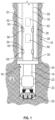
FIG. 1 shows a schematic diagram of a well construction system with a bottomhole assembly utilizing an anchor assembly of the present disclosure; -
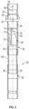
FIG. 2 shows a sectional view of profiles for an anchor in accordance with the present disclosure; -
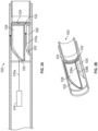
FIG. 3A and 3B sectionally and isometrically illustrate an embodiment of contours in accordance with the present disclosure; -
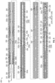
FIG. 4A shows an unfolded view of a section of a well tool where contours and anchors mate and align; -
FIG. 4B shows an unfolded view of a section of a well tool where contours and anchors are configured to mate only in a coded position; -
FIG. 5 is a line diagram of an exemplary drill string that includes an inner string and an outer string, wherein the inner string is connected to a first location of the outer string to drill a hole of a first size; -
FIG. 6A is a schematic illustration of a liner and running tool in accordance with an embodiment of the present disclosure; -
FIG. 6B is a schematic illustration of the running tool ofFIG. 6A as viewed along the line B-B; -
FIG. 6C is a schematic illustration of the running tool ofFIG. 6A as viewed along the line C-C; -
FIG. 7A is a schematic illustration of a portion of a running tool and a liner in accordance with an embodiment of the present disclosure having a position detecting system; and -
FIG. 7B is a detailed illustration of the marker ofFIG. 7A . - The present invention relates to an apparatus and methods for selectively connecting and / or disconnecting well components while at the surface or downhole. In some arrangements, the components may be concentrically arranged with an inner component disposed inside a bore or passage of an outer component. In other arrangements, the alignment may be eccentric or only partially overlapping As used herein, a "component" may be a downhole tool, a drill string, a bottomhole assembly (BHA), casing, liner, packer, or any other tool, instrument, equipment, or structure used while drilling, completing, or otherwise constructing, servicing, or operating a well.
- Embodiments of the present disclosure may include anchors that are self-aligning in the borehole. That is, as personnel bring the two components into mating engagement, one or both of the components rotate or move relative to one another to allow the anchors to properly orient and engage. The orientation, or alignment, may have a circumferential, radial, and / or axial component. This process may be done automatically or controlled by personnel. The features that enable the self-alignment are referred to as "contours" or "ramps," and are discussed in further detail below.
- The teachings of the present disclosure may be advantageously applied to a variety of well tools and systems. One non-limiting application for anchors according to the present disclosure is liner drilling. Liner drilling may be useful for drilling a borehole in underground formations with at least one formation that has a significantly different formation pressure than an adjacent formation or where time dependent unstable formations do not allow sufficient time to case off the hole in a subsequent run.
- In
Fig. 1 , there is shown an embodiment of aliner drilling system 10 that may use anchoring devices according to the present disclosure. The teachings of the present disclosure may be utilized in land, offshore or subsea applications. InFIG.1 , a laminatedearth formation 12 is intersected by aborehole 14. A BHA 16 is conveyed via adrill string 18 into theborehole 14. Thedrill string 18 may be jointed drill pipe or coiled tubing, which may include embedded conductors for power and / or data for providing signal and / or power communication between the surface and downhole equipment. The BHA 16 may include adrill bit 20 for forming theborehole 14. The BHA 16 may also include asteering unit 22 and adrilling motor 23. Other tools and devices that may be included in theBHA 10 include steering units, MWD/LWD tools that evaluate a borehole and / or surrounding formation, stabilizers, downhole blowout preventers, circulation subs, mud pulse instruments, mud turbines, etc. When configured as a liner drilling assembly to perform liner drilling, theBHA 16 utilizes areamer 24 and aliner assembly 26. Theliner assembly 26 may include awellbore tubular 28 and aliner bit 30. - An
anchor assembly 50 may be used to selectively connect theliner assembly 26 with thedrill string 18. In one embodiment, theanchor assembly 50 may include atorque anchor 52 and aweight anchor 54 that selectively engage with atorque profile 56 and aweight profile 58, respectively. By selectively, it is meant that theanchor assembly 50 may be remotely activated and / or deactivated multiple times using one or more control signals and while theanchor assembly 50 is in the borehole 14 or at the surface. While thetorque anchor 52 is shown uphole of theweight anchor 54, their relative positions may also be reversed. - The
anchors drill string 18 and may be members such as ribs, teeth, rods, or pads that can be shifted between a retracted and a radially extended position using anactuator 60. In some embodiments, theanchors actuator 60 may be electrically, electro-mechanically, or hydraulically energized. As shown, theanchors anchor communication module 62 configured to receive control signals for operating theanchor assembly 50 and to transmit signals to the surface (e.g., signals indicating the operating state or condition of the anchor assembly 50). - Referring now to
Fig. 2 , there is shown in a sectional view theprofiles anchors 52, 54 (Fig. 1 ) engage. Theprofiles inner surface 59 that defines apassage 61 of theliner assembly 26. - In one embodiment, the
profile 56 may be a recessed area formed in theinner surface 59 of theliner assembly 26 and that is shaped to allow the extension of theanchors 52 into the recessedarea 61 in any circumferential orientation of the inner and outer component and to self-align theliner assembly 26 with the drill string 18 (Fig. 1 ). For instance, theramp section 70 may protrude from theinner surface 59 and define a ramp surface that guides theanchor 52 to a predetermined alignment with a second component. Theprofile 56 may include acurved ramp section 70 and an axially aligned spline 72 (or load flank) that join at ajuncture 74. Thespline 72 may be considered an axially aligned shoulder. Theprofile 56 may also include acircumferential groove 80 that is chamfered at the lower terminal end of theramp section 70. The curvature and surface defining theramp section 70 are selected to present a helix-like structure against which the anchor 52 (Fig. 1 ) can slide toward thegroove 80 in a manner that allows/causes thedrill string 18 to rotate. In some arrangements, a ramp section, similar toramp section 70, can be formed on theanchor 52. - In one non-limiting embodiment, a
ramp tangent 91 forms anacute angle 91 with alongitudinal axis 95 of theanchor assembly 50. Theacute angle 91 may be between 1 degree and 90, between 1 degree and 70 degrees, or between 1 degree and less than 70 degrees. For surfaces that do not have a curvature, the ramp tangent may be the slope of the straight line defining the surface. Thespline 72, which is parallel with the longitudinal axis (or axis of symmetry), prevents further rotation in the direction thedrill string 18 rotates while sliding along thesplines 72 and moves toward thegroove 80. This rotational direction is shown witharrow 76. Thus, torque transfer between thedrill string 18 and theliner assembly 26 occurs at thespline 72 when the drill string is rotated in the direction shown byarrow 76. It should be noted that torque transfer in the opposite rotational direction can occur when theanchor 52 is positioned between theparallel shoulders groove 80. Axial loading from thedrill string 18 to theliner assembly 26 occurs when thedrill string 16 is axially displaced in the direction shown witharrow 78. Downward axial movement is stopped when theanchor 52 contacts the surfaces of thecircumferential groove 80. Thegroove 80 may be partially or completely circumferential. - The sidewalls of the
region 56 with theramp 70 and thespline 72 and thegroove 80 may have a stress optimized shape, that allows to transfer the loads axially and torsional and to withstand a predefined differential pressure during the later following cementing procedure or other applications. In one embodiment, theprofile 58 may be a recessed area in an inner wall of theliner assembly 26 that is shaped as a circumferential groove with anendstop shoulder 90. Thegroove 90 may include a stress reducing multi-centerpoint arc contour 92. - Referring to
Figs. 3A-B , there is shown a section of adownhole tool 500 whereinshoulders 528 are formed. Theshoulders 528 are separated bycavities 532, one of which is shown. Ananchor 516, when moving in an axial direction, contacts and slides along asurface 530 that projects radially inward from a wall of thedownhole tool 500. Thesurface 530 may be considered a "ramp." The axial direction may be the uphole or downhole direction. Thesurface 530 forces theanchor 516 to move along a pre-defined path as shown byline 516a. Awall 534 of a groove, which may be partially or completely circumferential, blocks further movement of theanchor 516 in the axial direction. Further, opposingsurfaces - The contours or ramps of the present disclosure are susceptible to numerous variations. In some embodiments, one or more surfaces defining the ramp (or contour) may be non-linear. The non-linear surfaces may be defined by a radius, a mathematic relationship (e.g., a polynomial), or an arbitrary curvature. In some embodiments, one or more of the surfaces defining the ramp, may use straight lines. In some embodiments, the ramp may use a composite geometry using different types of non-linear surface and / or linear surfaces. For instances, the linear surfaces may use different slopes. Thus, the ramp contour may be defined by one or more curves, straight lines, different curves, straight lines having different slopes, and combinations of curves and straight lines.
-
FIGS 4A-B illustrate various configurations ofanchors 52 andcontours 56 according to the present disclosure.Fig. 4A illustrates profiles in an "unwrapped" form.Anchors 52 contact and slide along surfaces of theprofiles 56. While threeprofiles 56 are shown, it should be understood that greater or fewer may be used. InFIG. 4A , there are shown a plurality ofanchors 52 and associatedcontours 56. Thus, some embodiments may have one anchor and one contour and other embodiments may have more than one anchor and associated contour.FIG. 4B illustrates a "keyed" or "coded" configuration for ananchors 52 andcontours 56. As a non-limiting example, there are twoanchors 52 and twocontours 56. Thus, an anchor assembly that has three or more anchors would not be able to mate or pass through thecontours 56. Thus, using a mismatch of in the number of anchors and contours is one non-limiting way to selective mate anchors and contours. - The anchors of the present disclosure may be configured to principally transmit force in one or more selected modes (e.g., rotationally, axially, torque, compression, tension, etc.). As discussed below, the
profile 56, in addition to providing a self-alignment function illustrated inFig. 4A , can transfer torque and axial loading in selected directions (e.g., in the downhole direction to push theliner assembly 26 through a high friction zone or a horizontal section) between thedrill string 18 and theliner assembly 26. Theprofile 58 can transfer axial loadings principally in the uphole direction between thedrill string 18 and theliner assembly 26. - In one embodiment, a
marker tube assembly 100 may be positioned between theprofile 56 and theprofile 58 or any location on theliner assembly 26. Themarker tube assembly 100 needs only to have a known or predetermined position relative to another location on theliner assembly 26. - Referring to
Figs. 1 and2 , in an illustrative mode of operation, theliner assembly 26 is positioned in theborehole 14. Later, thedrill string 18 is lowered into thepassage 61 of theliner assembly 26. Connecting theliner assembly 26 to thedrill string 18 may require these two components to have a predetermined alignment, which may be a circumferential, radial and / or axial relative alignment. - The
marker tube assembly 100 may be used to locate thetorque profile 56. In some embodiments, theprofiles 58 may act as the grooves for themarker tube assembly 100. At that time, thetorque anchor 52 may be extended using a control signal sent from a surface location. Alternatively, the extension may occur during an automatic mode triggered by the marker tube downhole. In another variation, the marker itself is a predefined shaped liner contour that matches with the sliding anchor profile and allows the engagement only in this position where the inner and outer part acts as a keylock mechanism. - Alternatively, if the
anchors 52 are already extended or generally fixed, the number or circumferential position of the anchor(s) 52 can encode a certain position which can mate only to a similar counterpart as shown inFig. 4B . That is, the anchors(s) 52 can only enter the profile(s) 56 if there is a predetermined rotational alignment. - With the
torque anchor 52 extended, thedrill string 18 is lowered (i.e., moved in the downhole direction) until thetorque anchor 52 contacts theramp section 70. Further lowering causes thedrill string 18 to rotate until thetorque anchor 52 is seated at a shoulder of thegroove 80. At this point, theliner assembly 26 to thedrill string 18 have the predetermined circumferential, radial and / or axial alignment. Further rotation of thedrill string 18 can transmit torque to theliner assembly 26 via the physical contact between thetorque anchor 52 and thespline 72. Torque may also be transmitted using theshoulder 81, depending on the rotating direction. As noted previously, this process may be done using personnel inputs or automatically. - With the
drill string 18 and theliner assembly 26 now properly aligned, the weight anchors 54 can be extend since theweight profile 58 may be an entirely circumferential groove that allows theanchors 54 to be extended independently from any rotational position. Then we lift up theinner drill string 18 and thedrill string 18 can be pulled in the uphole direction until theweight anchor 54 contacts theendstop shoulder 90 and physically engage the weight profile - Referring still to
Figs. 1 and2 , in one exemplary mode of operation, thedrill string 18 and theliner assembly 26 are tripped downhole and drilling commences. During this time,drill bit 20 forms the primary bore and thereamer 24 enlarges the primary bore. Theanchor assembly 50 provides a physical engagement that allows thedrills string 18 to pull or push theliner assembly 26 through theborehole 14. During this time, thetorque anchor 52 principally transmits the torque necessary to rotate theliner assembly 26 and transmits a downhole-oriented force to push theliner assembly 26 downhole. Theweight anchor 54 principally transmits the forces necessary to keep theliner assembly 26 locked to thedrill string 18 in the uphole axial direction. More generally, the weight anchors 54 transmits forces in an axial direction, which is generally along the borehole. - From the above, it should be appreciated that what has been described includes positioning, aligning, and orientating systems / methodologies that use matching between anchor and cavities lock and key functionality by number, shape, position. These systems eliminate the need for rotatable orientation of the components being connected. Additionally, stress optimization in regards to applied load from axial forces, torsion l load and finally pressure rating for the differential pressure versus the remaining wall thickness. A tilted contact shoulder to optimize the transmission path of the axial weight.
- It should be understood that the teachings of the present disclosure are not limited to any particular downhole application. Anchor assemblies of the present disclosure may also be used during completion, logging, workover, or production operations. In such applications, the components to be connected by a wireline, coiled tubing, production string, casing, or other suitable work string. One non-limiting application for the contours of the present disclosure relate to liner-drilling activities, which are described in greater detail below.
- Turning now to
FIG. 5 , a schematic line diagram of anexample string 200 that includes aninner string 210 disposed in anouter string 250 is shown. In this embodiment, theinner string 210 is adapted to pass through theouter string 250 and connect to the inside 250a of theouter string 250 at a number of spaced apart locations (also referred to herein as the "landings" or "landing locations"). The shown embodiment of theouter string 250 includes three landings, namely alower landing 252, amiddle landing 254 and anupper landing 256. Theinner string 210 includes a drilling assembly or disintegrating assembly 220 (also referred to as the "bottomhole assembly") connected to a bottom end of atubular member 201, such as a string of jointed pipes or a coiled tubing. Thedrilling assembly 220 includes a first disintegrating device 202 (also referred to herein as a "pilot bit") at its bottom end for drilling a borehole of afirst size 292a (also referred to herein as a "pilot hole"). Thedrilling assembly 220 further includes asteering device 204 that in some embodiments may include a number offorce application members 205 configured to extend from thedrilling assembly 220 to apply force on awall 292a' of thepilot hole 292a drilled by thepilot bit 202 to steer thepilot bit 202 along a selected direction, such as to drill a deviated pilot hole. Thedrilling assembly 220 may also include a drilling motor 208 (also referred to as a "mud motor") 208 configured to rotate thepilot bit 202 when a fluid 207 under pressure is supplied to theinner string 210. - In the configuration of
FIG. 5 , thedrilling assembly 220 is also shown to include an underreamer 212 that can be extended from and retracted toward a body of thedrilling assembly 220, as desired, to enlarge thepilot hole 292a to form awellbore 292b, to at least the size of the outer string. In various embodiments, for example as shown, thedrilling assembly 220 includes a number of sensors (collectively designated by numeral 209) for providing signals relating to a number of downhole parameters, including, but not limited to, various properties or characteristics of aformation 295 and parameters relating to the operation of thestring 200. Thedrilling assembly 220 also includes a control circuit (also referred to as a "controller") 224 that may include circuits 225 to condition the signals from thevarious sensors 209, a processor 226, such as a microprocessor, a data storage device 227, such as a solid-state memory, and programs 228 accessible to the processor 226 for executing instructions contained in the programs 228. The controller 224 communicates with a surface controller (not shown) via asuitable telemetry device 229a that provides two-way communication between theinner string 210 and the surface controller. Furthermore, a two-way communication can be configured or installed between subcomponents of multiple parts of the BHA. Thetelemetry device 229a may utilize any suitable data communication technique, including, but not limited to, mud pulse telemetry, acoustic telemetry, electromagnetic telemetry, and wired pipe. Apower generation unit 229b in theinner string 210 provides electrical power to the various components in theinner string 210, including thesensors 209 and other components in thedrilling assembly 220. Thedrilling assembly 220 also may include a second or multiplepower generation devices 223 capable of providing electrical power independent from the presence of the power generated using the drilling fluid 207 (e.g., thirdpower generation device 240b described below). - In various embodiments, such as that shown, the
inner string 210 may further include a sealing device 230 (also referred to as a "seal sub") that may include a sealingelement 232, such as an expandable and retractable packer, configured to provide a fluid seal between theinner string 210 and theouter string 250 when the sealingelement 232 is activated to be in an expanded state. Additionally, theinner string 210 may include aliner drive sub 236 that includesattachment elements outer string 250. Theinner string 210 may further include a hanger activation device or sub 238 havingseal members rotatable hanger 270 in theouter string 250. Theinner string 210 may include a thirdpower generation device 240b, such as a turbine-driven device, operated by the fluid 207 flowing through theinner sting 210 configured to generate electric power, and a second two-way telemetry device 240a utilizing any suitable communication technique, including, but not limited to, mud pulse, acoustic, electromagnetic and wired pipe telemetry. Theinner string 210 may further include a fourthpower generation device 241, independent from the presence of a power generation source usingdrilling fluid 207, such as batteries. Theinner string 210 may further includepup joints 244, aburst sub 246, and other components, such as, but not limited to, a release sub that releases parts of the BHA on demand or at reaching predefined load conditions. - Still referring to
FIG. 5 , theouter string 250 includes aliner 280 that may house or contain a second disintegrating device 251 (e.g., also referred to herein as a reamer bit) at its lower end thereof. Thereamer bit 251 is configured to enlarge a leftover portion ofhole 292a made by thepilot bit 202. In aspects, attaching the inner string at thelower landing 252 enables theinner string 210 to drill thepilot hole 292a and theunder reamer 212 to enlarge it to the borehole ofsize 292 that is at least as large as theouter string 250. Attaching theinner string 210 at themiddle landing 254 enables thereamer bit 251 to enlarge the section of thehole 292a not enlarged by the under reamer 212 (also referred to herein as the "leftover hole" or the "remaining pilot hole"). Attaching theinner string 210 at theupper landing 256, enables cementing anannulus 287 between theliner 280 and theformation 295 without pulling theinner string 210 to the surface, i.e., in a single trip of thestring 200 downhole. Thelower landing 252 includes afemale spline 252a and acollet grove 252b for attaching to theattachment elements liner drive sub 236. Similarly, themiddle landing 254 includes afemale spline 254a and acollet groove 254b and theupper landing 256 includes afemale spline 256a and acollet groove 256b. Any other suitable attaching and/or latching mechanisms for connecting theinner string 210 to theouter string 250 may be utilized for the purpose of this disclosure. - The
outer string 250 may further include aflow control device 262, such as a flapper valve, placed on the inside 250a of theouter string 250 proximate to itslower end 253. InFIG. 2 , theflow control device 262 is in a deactivated or open position. In such a position, theflow control device 262 allows fluid communication between thewellbore 292 and the inside 250a of theouter string 250. In some embodiments, theflow control device 262 can be activated (i.e., closed) when thepilot bit 202 is retrieved inside theouter string 250 to prevent fluid communication from thewellbore 292 to the inside 250a of theouter string 250. Theflow control device 262 is deactivated (i.e., opened) when thepilot bit 202 is extended outside theouter string 250. In one aspect, theforce application members 205 or another suitable device may be configured to activate theflow control device 262. - A reverse
flow control device 266, such as a reverse flapper valve, also may be provided to prevent fluid communication from the inside of theouter string 250 to locations below the reverseflow control device 266. Theouter string 250 also includes ahanger 270 that may be activated by thehanger activation sub 238 to anchor theouter string 250 to thehost casing 290. Thehost casing 290 is deployed in thewellbore 292 prior to drilling thewellbore 292 with thestring 200. In one aspect, theouter string 250 includes asealing device 285 to provide a seal between theouter string 250 and thehost casing 290. Theouter string 250 further includes areceptacle 284 at its upper end that may include aprotection sleeve 281 having afemale spline 282a and acollet groove 282b. Adebris barrier 283 may also be part of the outer string to prevent cuttings made by thepilot bit 202, the underreamer 212, and/or thereamer bit 251 from entering the space or annulus between theinner string 210 and theouter string 250. - To drill the
wellbore 292, theinner string 210 is placed inside theouter string 250 and attached to theouter string 250 at thelower landing 252 by activating theattachment elements liner drive sub 236 as shown. Thisliner drive sub 236, when activated, connects theattachment element 236a to thefemale splines 252a and theattachment element 236b to thecollet groove 252b in thelower landing 252. In this configuration, thepilot bit 202 and theunder reamer 212 extend past thereamer bit 251. In operation, thedrilling fluid 207 powers thedrilling motor 208 that rotates thepilot bit 202 to cause it to drill thepilot hole 292a while the underreamer 212 enlarges thepilot hole 292a to the diameter of thewellbore 292. Thepilot bit 202 and theunder reamer 212 may also be rotated by rotating thedrill string 200, in addition to rotating them by themotor 208. - In general, there are three different configurations and/or operations that are carried out with the string 200: drilling, reaming and cementing. In drilling a position the Bottom Hole Assembly (BHA) sticks out completely of the liner for enabling the full measuring and steering capability (e.g., as shown in
FIG. 5 ). In a reaming position, only the first disintegrating device (e.g., pilot bit 202) is outside the liner to reduce the risk of stuck pipe or drill string in case of well collapse and the remainder of the BHA is housed within theouter string 250. In a cementing position the BHA is configured inside theouter string 250 a certain distance from the second disintegrating device (e.g., reamer bit 251) to ensure a proper shoe track. - As provided herein, one-trip drilling and reaming operations are carried out with a BHA capable of being repositioned in a liner for the drilling of the pilot hole and the subsequent reaming. In some embodiments, fully circular magnetic rings in the liner and/or the running tool provide surface information as to a position of a running tool with respect to the liner when reconnecting to the liner. Further, position sensors can confirm alignment to various recesses in the liner for attachment. Axial loads can be transmitted through the liner at spaced locations separate from torsional loads with the attachment elements (e.g., blade arrays, anchors, etc.) spaced out on the running tool. In some embodiments, an emergency release can retract the blades from the opposing recesses to allow the running tool to be removed while opening the tool for flow. Proximity sensors in conjunction with the electromagnetic field sensed by the running tool allows alignment between the blades and the liner recesses. Blades are link driven with the link having offset centers to reduce stress.
- The running tool provides the connection between the inner string and the liner during steerable liner drilling. This connection, in accordance with embodiments of the present disclosure, can be infinitely engaged and released via downlinks. In some embodiments, the connection can also be established at different positions within the liner, depending on the operation that is being performed. The connection, as provided in accordance with various embodiments of the present disclosure, can be realized by the use of engagement modules (including, e.g., in one non-limiting embodiment, blade-shaped anchors) that are designed to transmit rotational forces from an over ground turning device (e.g., top drive) to the liner. The blade-shaped anchors can support both axial forces (e.g., liner weight or pushing forces acting on the liner to overcome, for example, high friction zones, etc.) and the rotational reaction forces due to the liner/formation interaction. The liner, in accordance with various embodiments, can include inner contours in order to host or receive the anchors. In summary, a downlink activated connection/transmission (e.g., the anchors) is optimized to handle or manage high loads.
- Running tools as provided herein enable systems that combine drilling, reaming, liner setting, and cementing processes into a single run. The processes of setting a liner and cementing during a single trip demands for a frequent liner-drill/cementing-string connect/disconnect procedure. Running tools as provided herein can accomplish such operation through incorporation of a set of limitless extendable and retractable anchors that support and transmit axial forces (e.g., liner weight or pushing forces acting on the liner to overcome, for example, high friction zones, etc.) and torque. In some embodiments, torque anchors configured to transmit torque and/or apply pushing forces to the liner are physically or spatially separated from weight anchors configured to support the liner weight. The liner is configured with associated inner contours in order to house or receive the anchors. The number of anchors located on or at each module (e.g., torque anchor module, weight anchor module) can be different. Such difference in number(s), shape, size, latching and/or contact faces, etc. can be provided to insure proper latching and to avoid misfits.
- Running tools as provided herein can be used for running cycles. One non-limiting running cycle is as follows. In order to start a new operation (such as rathole reaming or cementing) the running tool disengages. Such disengagement can be, for example, initiated or caused by a downlink and instructions or commands transmitted from the surface, triggered by internal tool sub routines, or started by gathering downhole information that reaches pre-selected thresholds. The running tool is moved to and confirms a new position within the liner. In some embodiments, the location of the running tool can be detected by a position detection system. The position detection system includes a marker and a position sensor. By way of a non-limiting example, the position may be measured by a magnetic marker/Hall sensor combination, gamma marker/detector, liner contour/acoustic sensor, or other marker/detector combination, as known in the art. At the new location, the running tool re-engages to the liner. The engagement can be caused by a downlink, triggered by internal tool sub routines, or started by gathering downhole information that reaches pre-selected thresholds. The above noted inner contours on the liner can be used for self-alignment of the running tool by engagement with the anchors. The movement and engagement amount of the anchors can be monitored, confirmed, and measured by an LVDT (linear variable differential transformer) or any inductive, capacitive, or magnetic sensor system and sent to the surface for confirmation. As such, a downhole operation can be continued with the running tool being connected to the liner at a different location than prior to movement of the running tool.
- The above described position detection system may additionally include, in some embodiments, an acoustic sensor which is configured to detect an inner contour of the liner. In such configurations, identifying the location of the running tool inside the liner may be done by correlating the depth of the running tool and the inner contour of the liner.
- The running tool is subject to very high forces and torques due to both its position within the drill string and the presence of the liner. By way of non-limiting example, the transmission of the torque and the axial forces from the inner string to the liner are separated in order to handle those high loads (e.g., separate torque-anchor and weight-anchor modules with separate associated anchors). In some embodiments, a complex geometry supports the weight/torque transmission. In some embodiments, the anchors are extended (or deployed) by default such that the liner cannot be lost downhole during a power/communication loss. In some non-limiting embodiments, the extending or deploying force applied to the anchors can be provided by coil springs. If power/communication cannot be re-established and the drill string is to be retrieved without the liner, the anchors can be permanently retracted by the use of a drop ball. In such an embodiment, the ball can activate a purely mechanical release mechanism powered by a circulating drilling fluid to thus retract the anchors. In some embodiments, the anchors can be pulled in by pulling the anchors against a contact surface to force the anchors to collapse inward and lose engagement between the running tool and the liner. While drop balls are used in the described embodiment of the present disclosure, the term "drop ball" also includes any other suitable object, e.g., bars, darts, plugs, and the like.
-
FIGS. 6A-6C illustrate various views of aliner 300 supported by a runningtool 302 are shown.FIG. 6A is a side view illustration of the liner and runningtool 300.FIG. 6B is a cross-sectional illustration of theliner 300 and runningtool 302 as viewed along the line B-B ofFIG. 6A and FIG. 6C a cross-sectional illustration of theliner 300 and runningtool 302 as viewed along the line C-C ofFIG. 6A . - The running
tool 302 is configured on and along astring 304. Theinner string 304 extends up-hole (e.g., to the left inFIG. 6A ) and down-hole (e.g., to the right inFIG. 6A ). Down-hole relative to the runningtool 302 is a bottom hole assembly (BHA) 306. TheBHA 306 can be configured and include components as described above. - To enable interaction between the
liner 300 and the runningtool 302, as provided in accordance with some embodiments of the present disclosure, theliner 300 includes one or more runningtool engagement sections 307. As shown, the runningtool engagement section 307 includes a firstliner anchor cavity 308 and a secondliner anchor cavity 310 that are defined as recesses or cavities formed on an interior surface of theliner 300. Theliner anchor cavities liner 300 and/or they can be spaced in an appropriate spacing around the tool axis (e.g., equally spaced). That is, theliner anchor cavities liner 300. Theliner anchor cavities tool 302. Theliner 300 can include multiple runningtool engagement sections 307 located at different distances or positions relative to a bottom end of a bore hole, and thus can enable extension of a BHA from the end of the liner to different lengths, as described herein. The runningtool engagement section 307 need not include all theliner anchor cavities - As shown, the running
tool 302 may include afirst engagement module 312 and a second engagement module 314 (also referred to as anchor modules). The first andsecond engagement modules tool 302. The firstliner anchor cavity 308 of theliner 300 is configured to receive one or more anchors of thefirst anchor module 312 and the secondliner anchor cavity 310 of theliner 300 is configured to receive one or more anchors of thesecond anchor module 314. Accordingly, the spacing of theliner anchor cavities liner 300 and the spacing of theanchor modules - The
first anchor module 312 includes one or morefirst anchors 316 and thesecond anchor module 314 includes one or moresecond anchors 318. Theanchors FIG. 6B , by way of non-limiting example, thefirst anchor module 312 includes threefirst anchors 316. Further, as shown inFIG. 6C , thesecond anchor module 314 includes fivesecond anchors 318. Theanchors anchor modules anchors respective module liner anchor cavity anchors respective module respective module tool 302 relative to theliner 300. Although shown with particular example numbers of anchors in each anchor module, those of skill in the art will appreciate that any number of anchors can be configured in each of the anchor modules without departing from the scope of the present disclosure. - The engagement or
anchor modules - Movement of the anchors may also be axial, tangential, or circumferential relative to a cylindrical module body. Actuation or operation of the engagement modules, as used herein, can be an operation that is controlled from a surface controller or can be an operation of the anchors to engage or disengage from a surface or structure in response to a pre-selected or pre-determined event or detection of pre-selected conditions or events. In some embodiments, the actuation or operation of each anchor module can be independent from the other anchor modules. In other embodiments, the actuation or operation of different anchor modules can be a dependent or predetermined sequence of actuations.
- In some embodiments (depending on the module configuration) actuation can mean extension from the module into engagement with a surface that is exterior to the module (e.g., an interior surface of a liner) and/or disengagement from such surface. That is, operation/actuation can mean extension or retraction of anchors into or from engagement with a surface or structure. As noted above, in some non-limiting embodiments, the different anchors may be operated separately or collectively. The separate or collective operation can be referred to as dependent or independent operation. In the case of independent operation, for example, only a single anchor may be extended or retracted, or a particular set or number of anchors may be extended or retracted. Further, for example, a particular time-based sequence of particular or predetermined anchor extensions or retractions can be performed in order to engage or disengage with the liner.
- In some embodiments, the
first anchors 316 of thefirst module 312 can be configured to transmit torque in either direction (e.g., circumferentially) with respect to the runningtool 302 or thestring 304. In such a configuration, thefirst anchors 316 may be referred to as torque anchors and thefirst module 312 may be referred to as a torque anchor module. The shape of the torque anchors can allow torque transmission to the liner or liner components as well as transmitting axial forces in a downhole direction. The capability of applying axial forces in the downhole direction can be used for pushing the liner through high friction zones, to influence the set down weight of the reamer bit, to activate or to support the setting of a hanger or packer, or to activate other liner components and/or completion equipment. - The
second anchors 318 of thesecond module 314 can be configured to transmit axial forces in an uphole direction. The capability of applying axial forces in the uphole direction can be used for carrying the liner weight and therefor to influence a set down weight of the reamer bit, to activate or to support the setting of a hanger or packer, or to activate or shear off other liner components. In such a configuration, thesecond anchors 318 may be referred to as weight anchors and thesecond module 314 may be referred to as a weight anchor module. In one non-limiting example, thesecond module 314 can be configured to apply set down weight to a drill bit or reamer bit andinstrumentation BHA 306 for directional drilling. Thestring 304 continues to the surface as indicated on the left side ofFIG. 6A . Those of skill in the art will appreciate that torque anchors push the liner when weight is applied and weight anchors hold the liner or pull the liner when the string is pulled. - As noted, the
first anchors 316 and thesecond anchors 318 are selectively extendable into locations on the liner 300 (e.g.,liner anchor cavities 308, 310). Theliner 300 can be configured with repeated configurations ofliner anchor cavities tool 302 with theliner 300 at multiple locations along the length of theliner 300. Theanchors liner anchor cavities tool 302 and theliner 300. - One advantage enabled by engagement of the running
tool 302 at different locations along the length of theliner 300 is to have different extensions of theBHA 306 from the lower end of theliner 300 when drilling a pilot hole as opposed to reaming the pilot hole already drilled. For example, for directional drilling of a pilot hole theBHA 306 extends out more from the lower end of theliner 300 and so the running tool can be engaged at a lower (e.g., down-hole) position relative to theliner 300 than when a reamer bit is enlarging a pilot hole. - Because of the separation of the first and
second modules anchors respective modules anchors liner anchor cavities liner anchor cavities liner 300 at different locations with appropriate spacing relative to each other so that theanchors liner 300 and, thus, different extensions ofBHA 306 from the lower end of theliner 300 can be achieved. That is, in some embodiments, the distance between each firstliner anchor cavity 308 and each secondliner anchor cavity 310 of each pair of liner anchor cavities is constant. In other embodiments, the spacing may not be constant. Further, in some embodiments, the shape of a cavity along a length of a string can be different at different positions. Because the runningtool 302 can be moved and located at different positions within theliner 300, and such position can be indicative of an extension of theBHA 306, it may be desirable to monitor the position of the runningtool 302 within theliner 300. - In some embodiments, to enable position monitoring and/or controlled operation and/or automatic operations, the running
tool 302 can include one ormore electronics modules 319. Theelectronics module 319 can include one or more electronic components, as known in the art, to enable control of the runningtool 300, such as determining the engaging and disengaging, and/or enable communication with the surface and/or with other downhole components, including, but not limited to, theBHA 306. Theelectronics module 319 can be part of or form a downlink that enables operation as describe herein. In other configurations, theelectronics module 319 can be replaced by an electronics device, such as an electrical wire, that enables transmission of electrical signals to and/or from the runningtool 302. - Turning now to
FIGS. 7A-7B , schematic illustrations of aliner 400 having a liner part (e.g., position marker 420) that is part of aposition detection system 425 in accordance with an embodiment of the present disclosure are shown. Although shown and described inFIGS. 7A-7B with various specific components configured in and on the runningtool 402 and theliner 400, those of skill in the art will appreciate that alternative configurations with the presently described components located within a liner are possible without departing from the scope of the present disclosure. In the non-limiting example, such as that shown inFIGS. 7A-7B , the liner part of theposition detection system 425 is a magnetic marker. - That is, the
position detection system 425 can be configured on the liners (liner 400) or running tools (running tool 402) of embodiments of the present disclosure, such asliner 300 or runningtool 302 ofFIG. 6A . In accordance with the embodiment ofFIGS. 7A-7B , aposition marker 420 is based on a magnetic ring configuration that is installed with theliner 400. However, the marker may also be located in the runningtool 302. Those of skill in the art will appreciate that theposition marker 420 can take any number of configurations without departing from the scope of the present disclosure. For example, magnetic markers, gamma markers, capacitive marker, conductive markers, tactile/mechanical components, etc. can be used to determine relative position between the liner and the running tool (e.g., in an axial and/or rotational manner to each other) and thus comprise one or more features of a position marker in accordance with the present disclosure. As shown, the marker is placed on the outside liner part and asensor 427 of thedetection system 425 is placed in the runningtool 402. Thesensor 427 is coupled todownhole electronics 419 within the running tool 402 (e.g., part of an electronics module, downlink, etc.). Asensor 427 can be a Hall sensor that detects the appearance and strength of a magnetic field. Thedownhole electronics 419 can be one or more electronic components that are configured in or on the runningtool 402, and can be part of an electronics module (e.g.,electronics module 319 ofFIG. 6A ). In other embodiments, an electronics device (e.g., an electrical wire) can be used instead of thedownhole electronics 419. -
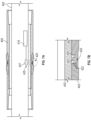
FIG. 7A is a cross-sectional illustration of a portion of theliner 400 including theposition marker 420 in accordance with an embodiment of the present disclosure.FIG. 7B is an enlarged illustration of theposition marker 420 as indicated by the dashed circle inFIG. 7A . - In some embodiments, the
position detection system 425 can be operably connected to or otherwise in communication withdownhole electronics 419 of the running tool 402 (e.g., in some embodiments,electronics module 319 ofFIG. 6A ). Thedownhole electronics 419 of the runningtool 402 can be used to communicate information to the surface, such as the position that is detected by theposition detection system 425. - Properly engaging, disengaging, and moving the running
tool 402 relative to theliner 400 is achieved through knowledge of the relative positions of the runningtool 402 and theliner 400. By knowing the relative position of theliner 400 and the runningtool 402, the anchor modules, described above, can be appropriately engaged with corresponding liner anchor cavities at different locations and thus adjustment of an extension of a BHA can be achieved. For example, the position detected by theposition detection system 425 can be communicated to the surface to inform about the approximate location of the liner anchor cavity pairs relative to respective anchor modules. - In the embodiment shown in
FIGS. 7A-7B , theposition marker 420 includes amagnetic ring 422 that has opposed north and south poles 424, 426 as shown. In other embodiments the opposite or differing pole orientation than that shown can be used. Themagnetic ring 422, in some embodiments, can be a full 360 degrees (e.g., wrap around the liner 400) or, in other embodiments, themagnetic ring 422 can be split such that less than 360 degrees is covered by themagnetic ring 422. Further, in other embodiments, themagnetic ring 422 can have overlapping ends such that themagnetic ring 422 wraps around more than 360° of theliner 400. Further still, other configurations can employ spaced magnetic buttons that form theposition marker 420. - The
magnetic ring 422 of theposition marker 420 creates an easily detected magnetic field that can be detected and/or interact with components or features of the liner or the running tool, depending on the particular configuration. Further, advantageously,position marker 420 as shown inFIGS. 7A-7B (e.g., magnetic rings 422) can make the orientation of the runningtool 402 in and relative to a liner irrelevant in detection of a signal. Accordingly, detection of the location of a liner anchor cavity can be easily achieved, e.g., by another magnetic component located on the liner. Detection can be achieved, in part, by processing carried out on an electronics module, and such detection can be communicated to the surface. Once the detection is communicated to the surface that a magnetic marker is detected, it may be desirable to position the runningtool 402 with precision so that extension of the anchors of the first and/or second anchor modules engage within respective liner anchor cavities (as described above). - The foregoing description is directed to particular embodiments of the present disclosure for the purpose of illustration and explanation. It will be apparent, however, to one skilled in the art that many modifications and changes to the embodiment set forth above are possible without departing from the scope of the disclosure. It is intended that the following claims be interpreted to embrace all such modifications and changes.
Claims (6)
- A well tool in a well operation performed in a borehole, comprising:a first component having a longitudinal axis;a second component having a passage for receiving the first component;a first anchor (52) on the first component;a second anchor (54) on the first component;a first profile (56) formed on an inner surface (59) defining the passage of the second component and configured to receive the first anchor (52); anda second profile (58) formed on the inner surface (59) defining the passage of the second component and configured to receive the second anchor (54);wherein the first profile (56) includes a ramp section (70), the ramp section (70) having a ramp contour defined by a ramp tangent, the ramp tangent forming an acute angle (91) with the longitudinal axis, the acute angle (91) of the ramp tangent being larger than 1 degree and smaller than 90 degrees, wherein the ramp section (70) protrudes from the inner surface (59) of the second component, the protruding ramp section (70) defining a ramp surface that projects radially inward and is configured to guide the first anchor (52) to a predetermined circumferential alignment with the second component,wherein the first profile (56) comprises first axially oriented shoulders (72, 81), a first circumferentially oriented shoulder (80) and a first cavity configured to receive the first anchor (52) formed on the inner surface (59), wherein the first anchor (52) is configured to apply a torque loading to a first axially oriented shoulder (72, 81) and an axial loading to the first circumferentially oriented shoulder (80),wherein the second profile (58) comprises a second circumferentially oriented shoulder (90) and a second cavity configured to receive the second anchor (54) formed on the inner surface (59), wherein the second anchor (54) is configured to apply an axial loading to the second circumferentially oriented shoulder (90), andwherein the first anchor (52) and the first circumferentially oriented shoulder (80) are configured to axially align the first and second components such that the second profile (58) can receive the second anchor (54).
- The well tool of claim 1, wherein the ramp contour is defined by at least one of: (i) a curve, (ii) a straight line, (iii) a plurality of different curves, (iv) a plurality of straight lines having different slopes, and (v) a combination of at least one curve and at least one straight line.
- The well tool of claim 1, wherein the first and/or second anchor (52, 54) includes a radially extending member that is one of: (i) fixed, and (ii) retractable.
- The well tool of claim 1, wherein the first component is a drill string (18) and the second component is a liner assembly (26).
- The well tool of claim 1, wherein the acute angle (91) is smaller than 50 degrees.
- A method for performing an operation in a borehole using a well tool that has a first component having a longitudinal axis and a second component having a passage for receiving the first component, the method comprising:disposing a first anchor (52) on the first component;disposing a second anchor (54) on the first component;forming a first profile (56) on an inner surface (59) defining the passage of the second component for receiving the first anchor (52); andforming a second profile (58) on the inner surface (59) defining the passage of the second component for receiving the second anchor (54);wherein the first profile (56) includes a ramp section (70), the ramp section (70) having a ramp contour defined by a ramp tangent, the ramp tangent forming an acute angle (91) with the longitudinal axis, the acute angle (91) of the ramp tangent being larger than 1 degree and smaller than 90 degrees, wherein the ramp section (70) protrudes from the inner surface (59) of the second component, the protruding ramp section (70) defining a ramp surface that projects radially inward and is configured to guide the first anchor (52) to a predetermined circumferential alignment with the second component;wherein the first profile (56) comprises first axially oriented shoulders (72, 81), a first circumferentially oriented shoulder (80) and a first cavity configured to receive the first anchor (52) formed on the inner surface (59), wherein the first anchor (52) is configured to apply a torque loading to a first axially oriented shoulder (72, 81) and an axial loading to the first circumferentially oriented shoulder (80),wherein the second profile (58) comprises a second circumferentially oriented shoulder (90) and a second cavity configured to receive the second anchor (54) formed on the inner surface (59), wherein the second anchor (54) is configured to apply an axial loading to the second circumferentially oriented shoulder (90), andwherein the first anchor (52) and the first circumferentially oriented shoulder (80) are configured to axially align the first and second components such that the second profile (58) can receive the second anchor (54);the method further comprising:axially moving the first component relative to the second component until the first anchor (52) and the first profile (56) align the first component and the second component in a predetermined alignment, wherein the first anchor (52) is guided to a predetermined circumferential alignment with the second component using the ramp section (70), and the first anchor (52) and the first circumferentially oriented shoulder (80) axially align the first and second components such that the second profile (58) can receive the second anchor (54); andapplying a torque loading to a first axially oriented shoulder (72, 81) using the first anchor (52), applying an axial loading to the first circumferentially oriented shoulder (80) using the first anchor (52) or applying an axial loading to the second circumferentially oriented shoulder (90) using the second anchor (54).
Applications Claiming Priority (2)
| Application Number | Priority Date | Filing Date | Title |
|---|---|---|---|
| US15/604,124 US11952842B2 (en) | 2017-05-24 | 2017-05-24 | Sophisticated contour for downhole tools |
| PCT/US2018/034426 WO2018218043A1 (en) | 2017-05-24 | 2018-05-24 | Sophisticated contour for downhole tools |
Publications (3)
| Publication Number | Publication Date |
|---|---|
| EP3631148A1 EP3631148A1 (en) | 2020-04-08 |
| EP3631148A4 EP3631148A4 (en) | 2021-03-17 |
| EP3631148B1 true EP3631148B1 (en) | 2025-06-25 |
Family
ID=64397062
Family Applications (1)
| Application Number | Title | Priority Date | Filing Date |
|---|---|---|---|
| EP18806172.5A Active EP3631148B1 (en) | 2017-05-24 | 2018-05-24 | Sophisticated contour for downhole tools |
Country Status (4)
| Country | Link |
|---|---|
| US (1) | US11952842B2 (en) |
| EP (1) | EP3631148B1 (en) |
| CA (1) | CA3064440A1 (en) |
| WO (1) | WO2018218043A1 (en) |
Families Citing this family (6)
| Publication number | Priority date | Publication date | Assignee | Title |
|---|---|---|---|---|
| US11713117B2 (en) * | 2020-03-31 | 2023-08-01 | Cnh Industrial America Llc | System and method for anchoring unmanned aerial vehicles to surfaces |
| NO346502B1 (en) * | 2020-06-25 | 2022-09-12 | Target Intervention As | Downhole tool and method for operating the same |
| CA3232408A1 (en) * | 2021-11-10 | 2023-05-19 | Halliburton Energy Services, Inc. | Debris resistant keyed running tool and method |
| US12209463B2 (en) * | 2023-05-30 | 2025-01-28 | Saudi Arabian Oil Company | Method and apparatus for retrieving tubing using disconnectable sub in a wellbore |
| US12352114B2 (en) | 2023-06-19 | 2025-07-08 | Halliburton Energy Services, Inc. | No-rotation latch coupling and latch for casing assemblies |
| US12612834B2 (en) * | 2023-11-30 | 2026-04-28 | Halliburton Energy Services, Inc. | Downhole orienting helix for operations requiring multiple orienting sequences |
Citations (1)
| Publication number | Priority date | Publication date | Assignee | Title |
|---|---|---|---|---|
| EP0834643B1 (en) * | 1996-10-01 | 2007-03-28 | Anadrill International SA | Method and apparatus for drilling and re-entering multiple lateral branches in a well |
Family Cites Families (38)
| Publication number | Priority date | Publication date | Assignee | Title |
|---|---|---|---|---|
| US3598183A (en) * | 1969-09-29 | 1971-08-10 | Byron Jackson Inc | Method and apparatus for treating wells |
| US5129453A (en) * | 1990-09-28 | 1992-07-14 | Dresser Industries, Inc. | Quick set well packer |
| US5579829A (en) | 1995-06-29 | 1996-12-03 | Baroid Technology, Inc. | Keyless latch for orienting and anchoring downhole tools |
| US5785357A (en) | 1995-09-22 | 1998-07-28 | Utd, Inc. | Locking joint |
| US5950744A (en) | 1997-10-14 | 1999-09-14 | Hughes; W. James | Method and apparatus for aligning drill pipe and tubing |
| CA2248287C (en) * | 1998-09-22 | 2002-05-21 | Laurier E. Comeau | Fail-safe coupling for a latch assembly |
| US6702040B1 (en) | 2001-04-26 | 2004-03-09 | Floyd R. Sensenig | Telescopic drilling method |
| US7240738B2 (en) * | 2003-01-28 | 2007-07-10 | Baker Hughes Incorporated | Self-orienting selectable locating collet and method for location within a wellbore |
| WO2004079151A2 (en) * | 2003-03-05 | 2004-09-16 | Weatherford/Lamb, Inc. | Drilling with casing latch |
| US7390032B2 (en) | 2003-08-01 | 2008-06-24 | Sonstone Corporation | Tubing joint of multiple orientations containing electrical wiring |
| US7757784B2 (en) * | 2003-11-17 | 2010-07-20 | Baker Hughes Incorporated | Drilling methods utilizing independently deployable multiple tubular strings |
| US7182153B2 (en) | 2004-01-09 | 2007-02-27 | Schlumberger Technology Corporation | Methods of casing drilling |
| US7299880B2 (en) | 2004-07-16 | 2007-11-27 | Weatherford/Lamb, Inc. | Surge reduction bypass valve |
| GB2449594B (en) | 2006-03-02 | 2010-11-17 | Baker Hughes Inc | Automated steerable hole enlargement drilling device and methods |
| SG143232A1 (en) | 2006-12-06 | 2008-06-27 | Vetco Gray Inc | Method for running casing while drilling system |
| US7926590B2 (en) * | 2007-10-03 | 2011-04-19 | Tesco Corporation | Method of liner drilling and cementing utilizing a concentric inner string |
| US7926578B2 (en) * | 2007-10-03 | 2011-04-19 | Tesco Corporation | Liner drilling system and method of liner drilling with retrievable bottom hole assembly |
| EP2065554B1 (en) | 2007-11-30 | 2014-04-02 | Services Pétroliers Schlumberger | System and method for drilling and completing lateral boreholes |
| US7708077B2 (en) | 2008-05-22 | 2010-05-04 | Tesco Corporation | Retrieval of bottom hole assembly during casing while drilling operations |
| US7845431B2 (en) | 2008-05-22 | 2010-12-07 | Tesco Corporation | Retrieval tool with slips for retrieving bottom hole assembly during casing while drilling operations |
| US20150176341A1 (en) * | 2010-01-28 | 2015-06-25 | Sunstone Technologies, Llc | Tapered Spline Connection for Drill Pipe, Casing, and Tubing |
| WO2012134705A2 (en) * | 2011-03-26 | 2012-10-04 | Halliburton Energy Services, Inc. | Single trip liner setting and drilling assembly |
| US9394763B2 (en) * | 2011-08-08 | 2016-07-19 | Schlumberger Technology Corporation | Multilateral location and orientation assembly |
| EP2557265A1 (en) | 2011-08-10 | 2013-02-13 | Geoservices Equipements | Device for extracting at least one gas contained in a circulating fluid. |
| EP3495603A1 (en) * | 2012-04-30 | 2019-06-12 | Halliburton Energy Services Inc. | Wellbore casing section with moveable portion for providing a casing exit |
| US9004195B2 (en) * | 2012-08-22 | 2015-04-14 | Baker Hughes Incorporated | Apparatus and method for drilling a wellbore, setting a liner and cementing the wellbore during a single trip |
| SG11201501714VA (en) * | 2012-09-06 | 2015-05-28 | Strata Energy Services Inc | Latching assembly |
| US9316074B2 (en) * | 2012-11-27 | 2016-04-19 | Baker Hughes Incorporated | Resettable selective locking device |
| US9518441B2 (en) * | 2013-05-07 | 2016-12-13 | Freudenberg Oil & Gas, Llc | Expandable packing element and cartridge |
| MX376557B (en) | 2013-12-05 | 2025-03-07 | Halliburton Energy Services Inc | DIRECTIONAL CASES DURING DRILLING. |
| US10240439B2 (en) * | 2014-01-08 | 2019-03-26 | Halliburton Energy Services, Inc. | Running tool and liner hanger contingency release mechanism |
| WO2015109147A1 (en) * | 2014-01-20 | 2015-07-23 | Schlumberger Canada Limited | One trip liner drilling and cementing |
| US9453393B2 (en) * | 2014-01-22 | 2016-09-27 | Seminole Services, LLC | Apparatus and method for setting a liner |
| BR112017005874A2 (en) * | 2014-10-08 | 2018-02-06 | Halliburton Energy Services Inc | method and system of drilling a liner in a well, apparatus with a recoverable bottom set, and method of cementing liner in a well hole. |
| US10711527B2 (en) | 2015-07-27 | 2020-07-14 | Halliburton Energy Services, Inc. | Drill bit and method for casing while drilling |
| NO20161103A1 (en) * | 2015-10-14 | 2017-04-17 | Comitt Well Solutions Us Holding Inc | Positioning system |
| US10605038B2 (en) * | 2016-04-01 | 2020-03-31 | Halliburton Energy Services, Inc. | Latch assembly using on-board miniature hydraulics for RCD applications |
| US10329861B2 (en) * | 2016-09-27 | 2019-06-25 | Baker Hughes, A Ge Company, Llc | Liner running tool and anchor systems and methods |
-
2017
- 2017-05-24 US US15/604,124 patent/US11952842B2/en active Active
-
2018
- 2018-05-24 WO PCT/US2018/034426 patent/WO2018218043A1/en not_active Ceased
- 2018-05-24 CA CA3064440A patent/CA3064440A1/en not_active Abandoned
- 2018-05-24 EP EP18806172.5A patent/EP3631148B1/en active Active
Patent Citations (1)
| Publication number | Priority date | Publication date | Assignee | Title |
|---|---|---|---|---|
| EP0834643B1 (en) * | 1996-10-01 | 2007-03-28 | Anadrill International SA | Method and apparatus for drilling and re-entering multiple lateral branches in a well |
Also Published As
| Publication number | Publication date |
|---|---|
| BR112019024600A2 (en) | 2020-06-09 |
| US20180340377A1 (en) | 2018-11-29 |
| EP3631148A4 (en) | 2021-03-17 |
| WO2018218043A1 (en) | 2018-11-29 |
| CA3064440A1 (en) | 2018-11-29 |
| EP3631148A1 (en) | 2020-04-08 |
| US11952842B2 (en) | 2024-04-09 |
Similar Documents
| Publication | Publication Date | Title |
|---|---|---|
| US11952842B2 (en) | Sophisticated contour for downhole tools | |
| EP3631141B1 (en) | Apparatus and method for exchanging signals / power between an inner and an outer tubular | |
| US10731417B2 (en) | Reduced trip well system for multilateral wells | |
| EP2888431B1 (en) | Apparatus and method for drillng a wellbore, setting a liner and cementing the wellbore during a single trip | |
| CA2661169C (en) | Releasing and recovering tool | |
| EP3519664B1 (en) | Liner running tool and anchor systems and methods | |
| CN104903536B (en) | For the system and method for rotatably directional inclination device assembly | |
| NO347218B1 (en) | Frac sleeve system and method for non-sequential downhole operations | |
| NO349662B1 (en) | Inner and outer downhole structures having downlink activation | |
| US20150144401A1 (en) | Hydraulically actuated tool with electrical throughbore | |
| EP3485134B1 (en) | Backflow prevention assembly for downhole operations | |
| CA2895787C (en) | Apparatus and methods of running casing | |
| CA2879085C (en) | Pipe in pipe piston thrust system | |
| BR112019024600B1 (en) | WELL TOOL IN A WELL OPERATION AND METHOD FOR PERFORMING AN OPERATION IN A WELL USING A WELL TOOL | |
| BR112019024073B1 (en) | WELL TOOL IN A WELL OPERATION IN A WELL AND METHOD FOR PERFORMING AN OPERATION USING A WELL TOOL THAT HAS A FIRST COMPONENT AND A SECOND COMPONENT |
Legal Events
| Date | Code | Title | Description |
|---|---|---|---|
| STAA | Information on the status of an ep patent application or granted ep patent |
Free format text: STATUS: THE INTERNATIONAL PUBLICATION HAS BEEN MADE |
|
| PUAI | Public reference made under article 153(3) epc to a published international application that has entered the european phase |
Free format text: ORIGINAL CODE: 0009012 |
|
| STAA | Information on the status of an ep patent application or granted ep patent |
Free format text: STATUS: REQUEST FOR EXAMINATION WAS MADE |
|
| 17P | Request for examination filed |
Effective date: 20191222 |
|
| AK | Designated contracting states |
Kind code of ref document: A1 Designated state(s): AL AT BE BG CH CY CZ DE DK EE ES FI FR GB GR HR HU IE IS IT LI LT LU LV MC MK MT NL NO PL PT RO RS SE SI SK SM TR |
|
| AX | Request for extension of the european patent |
Extension state: BA ME |
|
| RIN1 | Information on inventor provided before grant (corrected) |
Inventor name: MELLES, HENNING Inventor name: EGGERS, HEIKO |
|
| DAV | Request for validation of the european patent (deleted) | ||
| DAX | Request for extension of the european patent (deleted) | ||
| A4 | Supplementary search report drawn up and despatched |
Effective date: 20210212 |
|
| RIC1 | Information provided on ipc code assigned before grant |
Ipc: E21B 17/02 20060101ALI20210208BHEP Ipc: E21B 23/01 20060101AFI20210208BHEP Ipc: E21B 7/20 20060101ALI20210208BHEP |
|
| STAA | Information on the status of an ep patent application or granted ep patent |
Free format text: STATUS: EXAMINATION IS IN PROGRESS |
|
| 17Q | First examination report despatched |
Effective date: 20230117 |
|
| P01 | Opt-out of the competence of the unified patent court (upc) registered |
Effective date: 20230526 |
|
| GRAP | Despatch of communication of intention to grant a patent |
Free format text: ORIGINAL CODE: EPIDOSNIGR1 |
|
| STAA | Information on the status of an ep patent application or granted ep patent |
Free format text: STATUS: GRANT OF PATENT IS INTENDED |
|
| INTG | Intention to grant announced |
Effective date: 20250328 |
|
| GRAS | Grant fee paid |
Free format text: ORIGINAL CODE: EPIDOSNIGR3 |
|
| GRAA | (expected) grant |
Free format text: ORIGINAL CODE: 0009210 |
|
| STAA | Information on the status of an ep patent application or granted ep patent |
Free format text: STATUS: THE PATENT HAS BEEN GRANTED |
|
| RAP3 | Party data changed (applicant data changed or rights of an application transferred) |
Owner name: BAKER HUGHES HOLDINGS LLC |
|
| AK | Designated contracting states |
Kind code of ref document: B1 Designated state(s): AL AT BE BG CH CY CZ DE DK EE ES FI FR GB GR HR HU IE IS IT LI LT LU LV MC MK MT NL NO PL PT RO RS SE SI SK SM TR |
|
| REG | Reference to a national code |
Ref country code: GB Ref legal event code: FG4D |
|
| REG | Reference to a national code |
Ref country code: CH Ref legal event code: EP |
|
| REG | Reference to a national code |
Ref country code: DE Ref legal event code: R096 Ref document number: 602018082962 Country of ref document: DE |
|
| REG | Reference to a national code |
Ref country code: CH Ref legal event code: EP |
|
| REG | Reference to a national code |
Ref country code: IE Ref legal event code: FG4D |
|
| PG25 | Lapsed in a contracting state [announced via postgrant information from national office to epo] |
Ref country code: FI Free format text: LAPSE BECAUSE OF FAILURE TO SUBMIT A TRANSLATION OF THE DESCRIPTION OR TO PAY THE FEE WITHIN THE PRESCRIBED TIME-LIMIT Effective date: 20250625 |
|
| REG | Reference to a national code |
Ref country code: LT Ref legal event code: MG9D |
|
| PG25 | Lapsed in a contracting state [announced via postgrant information from national office to epo] |
Ref country code: GR Free format text: LAPSE BECAUSE OF FAILURE TO SUBMIT A TRANSLATION OF THE DESCRIPTION OR TO PAY THE FEE WITHIN THE PRESCRIBED TIME-LIMIT Effective date: 20250926 |
|
| PG25 | Lapsed in a contracting state [announced via postgrant information from national office to epo] |
Ref country code: BG Free format text: LAPSE BECAUSE OF FAILURE TO SUBMIT A TRANSLATION OF THE DESCRIPTION OR TO PAY THE FEE WITHIN THE PRESCRIBED TIME-LIMIT Effective date: 20250625 |
|
| PG25 | Lapsed in a contracting state [announced via postgrant information from national office to epo] |
Ref country code: HR Free format text: LAPSE BECAUSE OF FAILURE TO SUBMIT A TRANSLATION OF THE DESCRIPTION OR TO PAY THE FEE WITHIN THE PRESCRIBED TIME-LIMIT Effective date: 20250625 |
|
| PG25 | Lapsed in a contracting state [announced via postgrant information from national office to epo] |
Ref country code: RS Free format text: LAPSE BECAUSE OF FAILURE TO SUBMIT A TRANSLATION OF THE DESCRIPTION OR TO PAY THE FEE WITHIN THE PRESCRIBED TIME-LIMIT Effective date: 20250925 |
|
| PG25 | Lapsed in a contracting state [announced via postgrant information from national office to epo] |
Ref country code: LV Free format text: LAPSE BECAUSE OF FAILURE TO SUBMIT A TRANSLATION OF THE DESCRIPTION OR TO PAY THE FEE WITHIN THE PRESCRIBED TIME-LIMIT Effective date: 20250625 |
|
| REG | Reference to a national code |
Ref country code: NL Ref legal event code: MP Effective date: 20250625 |
|
| PG25 | Lapsed in a contracting state [announced via postgrant information from national office to epo] |
Ref country code: NL Free format text: LAPSE BECAUSE OF FAILURE TO SUBMIT A TRANSLATION OF THE DESCRIPTION OR TO PAY THE FEE WITHIN THE PRESCRIBED TIME-LIMIT Effective date: 20250625 |
|
| PG25 | Lapsed in a contracting state [announced via postgrant information from national office to epo] |
Ref country code: PT Free format text: LAPSE BECAUSE OF FAILURE TO SUBMIT A TRANSLATION OF THE DESCRIPTION OR TO PAY THE FEE WITHIN THE PRESCRIBED TIME-LIMIT Effective date: 20251027 |
|
| REG | Reference to a national code |
Ref country code: AT Ref legal event code: MK05 Ref document number: 1806615 Country of ref document: AT Kind code of ref document: T Effective date: 20250625 |
|
| PG25 | Lapsed in a contracting state [announced via postgrant information from national office to epo] |
Ref country code: IS Free format text: LAPSE BECAUSE OF FAILURE TO SUBMIT A TRANSLATION OF THE DESCRIPTION OR TO PAY THE FEE WITHIN THE PRESCRIBED TIME-LIMIT Effective date: 20251025 |
|
| PG25 | Lapsed in a contracting state [announced via postgrant information from national office to epo] |
Ref country code: AT Free format text: LAPSE BECAUSE OF FAILURE TO SUBMIT A TRANSLATION OF THE DESCRIPTION OR TO PAY THE FEE WITHIN THE PRESCRIBED TIME-LIMIT Effective date: 20250625 Ref country code: SM Free format text: LAPSE BECAUSE OF FAILURE TO SUBMIT A TRANSLATION OF THE DESCRIPTION OR TO PAY THE FEE WITHIN THE PRESCRIBED TIME-LIMIT Effective date: 20250625 |
|
| PG25 | Lapsed in a contracting state [announced via postgrant information from national office to epo] |
Ref country code: CZ Free format text: LAPSE BECAUSE OF FAILURE TO SUBMIT A TRANSLATION OF THE DESCRIPTION OR TO PAY THE FEE WITHIN THE PRESCRIBED TIME-LIMIT Effective date: 20250625 |
|
| PG25 | Lapsed in a contracting state [announced via postgrant information from national office to epo] |
Ref country code: PL Free format text: LAPSE BECAUSE OF FAILURE TO SUBMIT A TRANSLATION OF THE DESCRIPTION OR TO PAY THE FEE WITHIN THE PRESCRIBED TIME-LIMIT Effective date: 20250625 |
|
| PG25 | Lapsed in a contracting state [announced via postgrant information from national office to epo] |
Ref country code: EE Free format text: LAPSE BECAUSE OF FAILURE TO SUBMIT A TRANSLATION OF THE DESCRIPTION OR TO PAY THE FEE WITHIN THE PRESCRIBED TIME-LIMIT Effective date: 20250625 |
|
| PG25 | Lapsed in a contracting state [announced via postgrant information from national office to epo] |
Ref country code: SK Free format text: LAPSE BECAUSE OF FAILURE TO SUBMIT A TRANSLATION OF THE DESCRIPTION OR TO PAY THE FEE WITHIN THE PRESCRIBED TIME-LIMIT Effective date: 20250625 |
|
| PG25 | Lapsed in a contracting state [announced via postgrant information from national office to epo] |
Ref country code: ES Free format text: LAPSE BECAUSE OF FAILURE TO SUBMIT A TRANSLATION OF THE DESCRIPTION OR TO PAY THE FEE WITHIN THE PRESCRIBED TIME-LIMIT Effective date: 20250625 |
|
| PG25 | Lapsed in a contracting state [announced via postgrant information from national office to epo] |
Ref country code: DK Free format text: LAPSE BECAUSE OF FAILURE TO SUBMIT A TRANSLATION OF THE DESCRIPTION OR TO PAY THE FEE WITHIN THE PRESCRIBED TIME-LIMIT Effective date: 20250625 |
|
| PG25 | Lapsed in a contracting state [announced via postgrant information from national office to epo] |
Ref country code: IT Free format text: LAPSE BECAUSE OF FAILURE TO SUBMIT A TRANSLATION OF THE DESCRIPTION OR TO PAY THE FEE WITHIN THE PRESCRIBED TIME-LIMIT Effective date: 20250625 |
|
| PLBE | No opposition filed within time limit |
Free format text: ORIGINAL CODE: 0009261 |
|
| STAA | Information on the status of an ep patent application or granted ep patent |
Free format text: STATUS: NO OPPOSITION FILED WITHIN TIME LIMIT |
|
| REG | Reference to a national code |
Ref country code: CH Ref legal event code: L10 Free format text: ST27 STATUS EVENT CODE: U-0-0-L10-L00 (AS PROVIDED BY THE NATIONAL OFFICE) Effective date: 20260507 |