EP3630519B1 - Tracked vehicle having motor coaxially arranged with drive wheel - Google Patents
Tracked vehicle having motor coaxially arranged with drive wheel Download PDFInfo
- Publication number
- EP3630519B1 EP3630519B1 EP18809825.5A EP18809825A EP3630519B1 EP 3630519 B1 EP3630519 B1 EP 3630519B1 EP 18809825 A EP18809825 A EP 18809825A EP 3630519 B1 EP3630519 B1 EP 3630519B1
- Authority
- EP
- European Patent Office
- Prior art keywords
- drive wheel
- motor
- drive
- track
- arrangement
- Prior art date
- Legal status (The legal status is an assumption and is not a legal conclusion. Google has not performed a legal analysis and makes no representation as to the accuracy of the status listed.)
- Active
Links
Images


Classifications
-
- B—PERFORMING OPERATIONS; TRANSPORTING
- B62—LAND VEHICLES FOR TRAVELLING OTHERWISE THAN ON RAILS
- B62D—MOTOR VEHICLES; TRAILERS
- B62D55/00—Endless track vehicles
- B62D55/08—Endless track units; Parts thereof
- B62D55/10—Bogies; Frames
-
- B—PERFORMING OPERATIONS; TRANSPORTING
- B62—LAND VEHICLES FOR TRAVELLING OTHERWISE THAN ON RAILS
- B62D—MOTOR VEHICLES; TRAILERS
- B62D55/00—Endless track vehicles
- B62D55/06—Endless track vehicles with tracks without ground wheels
-
- B—PERFORMING OPERATIONS; TRANSPORTING
- B60—VEHICLES IN GENERAL
- B60K—ARRANGEMENT OR MOUNTING OF PROPULSION UNITS OR OF TRANSMISSIONS IN VEHICLES; ARRANGEMENT OR MOUNTING OF PLURAL DIVERSE PRIME-MOVERS IN VEHICLES; AUXILIARY DRIVES FOR VEHICLES; INSTRUMENTATION OR DASHBOARDS FOR VEHICLES; ARRANGEMENTS IN CONNECTION WITH COOLING, AIR INTAKE, GAS EXHAUST OR FUEL SUPPLY OF PROPULSION UNITS IN VEHICLES
- B60K7/00—Disposition of motor in, or adjacent to, traction wheel
-
- B—PERFORMING OPERATIONS; TRANSPORTING
- B60—VEHICLES IN GENERAL
- B60K—ARRANGEMENT OR MOUNTING OF PROPULSION UNITS OR OF TRANSMISSIONS IN VEHICLES; ARRANGEMENT OR MOUNTING OF PLURAL DIVERSE PRIME-MOVERS IN VEHICLES; AUXILIARY DRIVES FOR VEHICLES; INSTRUMENTATION OR DASHBOARDS FOR VEHICLES; ARRANGEMENTS IN CONNECTION WITH COOLING, AIR INTAKE, GAS EXHAUST OR FUEL SUPPLY OF PROPULSION UNITS IN VEHICLES
- B60K7/00—Disposition of motor in, or adjacent to, traction wheel
- B60K7/0007—Disposition of motor in, or adjacent to, traction wheel the motor being electric
-
- B—PERFORMING OPERATIONS; TRANSPORTING
- B60—VEHICLES IN GENERAL
- B60K—ARRANGEMENT OR MOUNTING OF PROPULSION UNITS OR OF TRANSMISSIONS IN VEHICLES; ARRANGEMENT OR MOUNTING OF PLURAL DIVERSE PRIME-MOVERS IN VEHICLES; AUXILIARY DRIVES FOR VEHICLES; INSTRUMENTATION OR DASHBOARDS FOR VEHICLES; ARRANGEMENTS IN CONNECTION WITH COOLING, AIR INTAKE, GAS EXHAUST OR FUEL SUPPLY OF PROPULSION UNITS IN VEHICLES
- B60K7/00—Disposition of motor in, or adjacent to, traction wheel
- B60K7/0015—Disposition of motor in, or adjacent to, traction wheel the motor being hydraulic
-
- B—PERFORMING OPERATIONS; TRANSPORTING
- B60—VEHICLES IN GENERAL
- B60K—ARRANGEMENT OR MOUNTING OF PROPULSION UNITS OR OF TRANSMISSIONS IN VEHICLES; ARRANGEMENT OR MOUNTING OF PLURAL DIVERSE PRIME-MOVERS IN VEHICLES; AUXILIARY DRIVES FOR VEHICLES; INSTRUMENTATION OR DASHBOARDS FOR VEHICLES; ARRANGEMENTS IN CONNECTION WITH COOLING, AIR INTAKE, GAS EXHAUST OR FUEL SUPPLY OF PROPULSION UNITS IN VEHICLES
- B60K7/00—Disposition of motor in, or adjacent to, traction wheel
- B60K7/0023—Disposition of motor in, or adjacent to, traction wheel the motor being pneumatic
-
- B—PERFORMING OPERATIONS; TRANSPORTING
- B62—LAND VEHICLES FOR TRAVELLING OTHERWISE THAN ON RAILS
- B62D—MOTOR VEHICLES; TRAILERS
- B62D55/00—Endless track vehicles
-
- B—PERFORMING OPERATIONS; TRANSPORTING
- B62—LAND VEHICLES FOR TRAVELLING OTHERWISE THAN ON RAILS
- B62D—MOTOR VEHICLES; TRAILERS
- B62D55/00—Endless track vehicles
- B62D55/08—Endless track units; Parts thereof
- B62D55/104—Suspension devices for wheels, rollers, bogies or frames
-
- B—PERFORMING OPERATIONS; TRANSPORTING
- B62—LAND VEHICLES FOR TRAVELLING OTHERWISE THAN ON RAILS
- B62D—MOTOR VEHICLES; TRAILERS
- B62D55/00—Endless track vehicles
- B62D55/08—Endless track units; Parts thereof
- B62D55/12—Arrangement, location, or adaptation of driving sprockets
- B62D55/125—Final drives
-
- B—PERFORMING OPERATIONS; TRANSPORTING
- B62—LAND VEHICLES FOR TRAVELLING OTHERWISE THAN ON RAILS
- B62D—MOTOR VEHICLES; TRAILERS
- B62D55/00—Endless track vehicles
- B62D55/08—Endless track units; Parts thereof
- B62D55/14—Arrangement, location, or adaptation of rollers
-
- B—PERFORMING OPERATIONS; TRANSPORTING
- B62—LAND VEHICLES FOR TRAVELLING OTHERWISE THAN ON RAILS
- B62D—MOTOR VEHICLES; TRAILERS
- B62D55/00—Endless track vehicles
- B62D55/08—Endless track units; Parts thereof
- B62D55/18—Tracks
- B62D55/24—Tracks of continuously flexible type, e.g. rubber belts
- B62D55/244—Moulded in one piece, with either smooth surfaces or surfaces having projections, e.g. incorporating reinforcing elements
-
- B—PERFORMING OPERATIONS; TRANSPORTING
- B60—VEHICLES IN GENERAL
- B60K—ARRANGEMENT OR MOUNTING OF PROPULSION UNITS OR OF TRANSMISSIONS IN VEHICLES; ARRANGEMENT OR MOUNTING OF PLURAL DIVERSE PRIME-MOVERS IN VEHICLES; AUXILIARY DRIVES FOR VEHICLES; INSTRUMENTATION OR DASHBOARDS FOR VEHICLES; ARRANGEMENTS IN CONNECTION WITH COOLING, AIR INTAKE, GAS EXHAUST OR FUEL SUPPLY OF PROPULSION UNITS IN VEHICLES
- B60K7/00—Disposition of motor in, or adjacent to, traction wheel
- B60K2007/0038—Disposition of motor in, or adjacent to, traction wheel the motor moving together with the wheel axle
-
- B—PERFORMING OPERATIONS; TRANSPORTING
- B60—VEHICLES IN GENERAL
- B60K—ARRANGEMENT OR MOUNTING OF PROPULSION UNITS OR OF TRANSMISSIONS IN VEHICLES; ARRANGEMENT OR MOUNTING OF PLURAL DIVERSE PRIME-MOVERS IN VEHICLES; AUXILIARY DRIVES FOR VEHICLES; INSTRUMENTATION OR DASHBOARDS FOR VEHICLES; ARRANGEMENTS IN CONNECTION WITH COOLING, AIR INTAKE, GAS EXHAUST OR FUEL SUPPLY OF PROPULSION UNITS IN VEHICLES
- B60K7/00—Disposition of motor in, or adjacent to, traction wheel
- B60K2007/0061—Disposition of motor in, or adjacent to, traction wheel the motor axle being parallel to the wheel axle
-
- B—PERFORMING OPERATIONS; TRANSPORTING
- B60—VEHICLES IN GENERAL
- B60K—ARRANGEMENT OR MOUNTING OF PROPULSION UNITS OR OF TRANSMISSIONS IN VEHICLES; ARRANGEMENT OR MOUNTING OF PLURAL DIVERSE PRIME-MOVERS IN VEHICLES; AUXILIARY DRIVES FOR VEHICLES; INSTRUMENTATION OR DASHBOARDS FOR VEHICLES; ARRANGEMENTS IN CONNECTION WITH COOLING, AIR INTAKE, GAS EXHAUST OR FUEL SUPPLY OF PROPULSION UNITS IN VEHICLES
- B60K7/00—Disposition of motor in, or adjacent to, traction wheel
- B60K2007/0092—Disposition of motor in, or adjacent to, traction wheel the motor axle being coaxial to the wheel axle
-
- B—PERFORMING OPERATIONS; TRANSPORTING
- B60—VEHICLES IN GENERAL
- B60Y—INDEXING SCHEME RELATING TO ASPECTS CROSS-CUTTING VEHICLE TECHNOLOGY
- B60Y2200/00—Type of vehicle
- B60Y2200/20—Off-Road Vehicles
-
- B—PERFORMING OPERATIONS; TRANSPORTING
- B60—VEHICLES IN GENERAL
- B60Y—INDEXING SCHEME RELATING TO ASPECTS CROSS-CUTTING VEHICLE TECHNOLOGY
- B60Y2200/00—Type of vehicle
- B60Y2200/20—Off-Road Vehicles
- B60Y2200/25—Track vehicles
Definitions
- the present invention relates to a tracked vehicle according to the preamble of claim 1.
- Tracked vehicles normally comprise a pair of track assemblies, where each track assembly of the pair of track assemblies comprises a track support beam, a drive wheel, a plurality of road wheels and an endless track running over the drive wheel and said plurality of road wheels. Said drive wheel and said plurality of road wheels are rotatably secured to said track support beam. Said drive wheel is arranged to drive said endless track running over said drive wheel and said set of road wheels so as to propel the tracked vehicle.
- Such a tracked vehicle comprises a drive unit comprising said track assemblies and drive means for driving said drive wheels of the tracked vehicle, where said drive means may comprise any suitable engine/motor.
- WO2014182216A1 discloses a tracked vehicle having a track assembly comprising a track support beam configured to support a plurality of road wheels and a drive wheel. Said track support beam is supported by a vehicle chassis of the tracked vehicle by means of a suspension device allowing relative movement between the track support beam and the vehicle chassis.
- the tracked vehicle comprises a drive unit comprising said track support beam an electric motor which is connected to said at least one drive wheel and integrated in said track support beam in a longitudinal direction of said track support beam, said electric motor being be fixedly arranged to said track support beam.
- the electric motor still occupies space for other relevant components such as bushings and fastening arrangements for road wheel arms and spring arrangements.
- US 2007/029878 A1 discloses a tracked vehicle comprising a vehicle body and a track assembly pair according the preamble of independent claim 1.
- tracked vehicles are known from WO 2014/182235 A1 and US 2009/078528 A1 .
- An object of the present invention is to provide a tracked vehicle with a track assembly pair for driving the vehicle which facilitates high operational reliability and efficiency in which motor for said operation provides a compact solution.
- a tracked vehicle comprising a vehicle body and a track assembly pair, said track assembly pair being arranged to suspendedly support said vehicle body allowing relative movement between said vehicle body and each track assembly of said track assembly pair, each track assembly comprising a track support beam configured to support a plurality of road wheels, a drive wheel, and a motor for operating said drive wheel, an endless track being disposed around said road wheels and drive wheel, said motor being fixedly arranged to said track support beam, wherein said motor is arranged in connection to the drive wheel such that a motor axle essentially coaxially coincides with the centre axis of the drive wheel.
- the object of the invention is further achieved in that said motor is comprised in a drive arrangement, said drive arrangement further comprising a transmission device for transferring torque from said motor to said drive wheel and a brake member for braking the drive wheel, wherein at least one of said transmission device and said brake member is arranged in connection to the drive wheel so that it at least partly is accommodated within the periphery of the drive wheel in the direction transversal to a main direction of extension of the track assembly.
- said fastening arrangement comprises a claw configuration for supporting said drive wheel and drive arrangement, wherein non-rotating parts of said drive arrangement are arranged to be fixedly attached to said claw configuration, wherein said claw configuration comprises a right claw member and a left claw member for said attachment of said non-rotating parts, and a transversal portion from which said right claw member and a left claw member are arranged to project.
- the tracked vehicle may comprise one or more tracked vehicle units.
- the tracked vehicle comprises according to an embodiment more than one tracked vehicle unit, said vehicle units being articulately connected to each other.
- the tracked vehicle is according to an embodiment a tracked articulated vehicle.
- the tracked vehicle thus comprises opposite track assemblies, a right track assembly and the opposite track assembly constituting a left track assembly, said right and left track assemblies constituting said track assembly pair.
- each vehicle unit comprises such a track assembly pair.
- Each track support beam is further arranged to support a tension wheel.
- said motor is arranged in connection to the drive wheel so that the motor at least partly is accommodated within the periphery of the drive wheel in the direction transversal to a main direction of extension of the track assembly so as to allow said motor to move relative to said vehicle body together with said track assembly.
- a compact arrangement of the motor of the track assembly is provided making space available in the track assembly in connection to said track support beam.
- Said motor is arranged in connection to the drive wheel inside an internal space of said drive wheel or next to said drive wheel so that the motor at least partly is accommodated within the periphery of the drive wheel in the direction transversal to a main direction of extension of the track assembly so as to allow said motor to move relative to said vehicle body together with said track assembly.
- the drive wheel has an opening into said internal space of said drive wheel for receiving said motor.
- Said internal space has a ring-shaped cross section.
- Said internal space of the drive wheel has a transversal extension relative to the main direction of extension of the track assembly.
- the motor is according to an embodiment arranged to at least partly extend through said opening of said internal space of said drive wheel.
- the motor in the direction essentially perpendicular to the longitudinal direction and the transversal direction of the endless track is arranged within the periphery of the endless track.
- the motor is efficiently protected within the track assembly.
- the motor is accommodated within said drive wheel within the outer contours of the drive wheel.
- the motor is efficiently protected by the drive wheel.
- said motor is comprised in a drive arrangement, said drive arrangement further comprising a transmission device for transferring torque from said motor to said drive wheel and a brake member for braking the drive wheel, wherein at least one of said transmission device and said brake member is arranged in connection to the drive wheel so that it at least partly is accommodated within the periphery of the drive wheel in the direction transversal to a main direction of extension of the track assembly.
- the transmission device may be any suitable transmission device for transferring torque from said motor to said drive wheel.
- the transmission device comprises according to an embodiment a planetary gear and a transmission axle with an input axle configured to be coupled to said motor axle and an output axle configured to be coupled to said drive wheel for torque transfer to said drive wheel.
- said motor is an electric motor or a hydraulic motor, said motor comprising a stator and a rotor for providing a rotational movement of said motor axle relative to the stator for said operation of the drive wheel.
- the stator of the motor is fixedly arranged relative to said track support beam via a fastening arrangement and the rotor of the motor is arranged to drive said drive wheel.
- efficient operation of said tracked vehicle is obtained.
- the rotor of the motor is thus arranged to drive said drive wheel via said transmission device.
- the motor is according to an embodiment configured to be in a motor housing wherein said stator is fixedly arranged in said motor housing.
- said drive arrangement comprises a bearing configuration arranged to allow the drive wheel to rotate relative to the stator of the motor.
- the bearing configuration comprises according to an embodiment a rolling bearing.
- said fastening arrangement comprises a claw configuration for supporting said drive wheel and drive arrangement, wherein non-rotating parts of said drive arrangement are arranged to be fixedly attached to said claw configuration, wherein said claw configuration comprises a right claw member and a left claw member for said attachment of said non-rotating parts, and a transversal portion from which said right claw member and a left claw member are arranged to project.
- the fork configuration may have any suitable shape for supporting non rotating parts of said drive arrangement.
- the fork configuration may have supporting arms or claws having a supporting function and facilitating attachment of non-rotating parts of said drive arrangement. Said fork configuration is thus arranged to support said drive arrangement.
- Said stator of the motor is arranged to be fixedly attached to said fork configuration.
- Said stator of the motor is according to an embodiment arranged to be fixedly attached to said fork configuration via said motor housing.
- Non rotating parts of said drive arrangement are arranged to be fixedly attached to said fork configuration.
- Said fork configuration of said fastening arrangement is according to an embodiment an integrated part of said track support beam.
- Said fork configuration may be attached to said track support beam by means of any suitable attachment means such as e.g. by a welding joint.
- Said fork configuration is arranged at an end portion of said track support beam for supporting said drive wheel and hence drive arrangement and motor.
- Said fork configuration comprises a right claw member and a left claw member.
- Said fork configuration comprises a transversal portion from which said right claw member and a left claw member are arranged to project.
- said fastening arrangement comprises clamping members for clamping said stator to said fork configuration.
- Said clamping members are thus configured to be removably attached to said fork configuration for lamping said stator to said fork configuration.
- said tracked vehicle is a forestry machine, such as a forwarder.
- track support beam refers to a structural element arranged to support ground-engaging means such as e.g. an endless track as well as drive wheel and road wheels.
- skid beam refers to an example of a track support beam.
- track assembly refers to a unit of the tracked vehicle comprising track support beam, drive wheel and road wheels as well as a circumferential endless track, which unit is arranged to comprise ground-engaging means and configured to propel the vehicle and thus form at least part of a drive unit of the tracked vehicle.
- track assembly pair refers to opposite track assemblies of a vehicle unit of the vehicle, one track assembly constituting a right track assembly and the opposite track assembly constituting a left track assembly.
- articulated vehicle refers to a vehicle with at least a front and a rear vehicle unit which are pivotable relative to each other about at least one joint.
- vehicle body refers to any structure of a vehicle configured to support track assemblies of a tracked vehicle and may comprise or constitute the vehicle chassis.
- vehicle body may refer to a vehicle frame, one or more beams or the like.
- fork configuration refers to any suitable fork-like or claw like configuration for supporting non-rotating parts of a drive arrangement comprising a motor, and may have supporting arms or claws having a supporting function and facilitating attachment of non-rotating parts of said drive arrangement.
- a tracked vehicle 10 according to the present invention is illustrated, provided with a front vehicle unit 11 and a rear vehicle unit 12.
- Each of the front and rear vehicle unit comprises a track assembly pair 20.
- Said track assembly pair 20 is constituted by or comprised of a drive unit pair.
- Said track assembly pair 20 comprises two track assemblies 21 arranged on opposite sides of the vehicle 10.
- the respective track assembly 21 is constituted by or comprised of a drive unit.
- the respective track assembly 21 is constituted by a driving track assembly and is arranged for propulsion of the vehicle.
- the respective track assembly pair 20 is connected to an intermediate vehicle body 30, 32, such as a chassis beam.
- the front vehicle unit 11 comprises a vehicle body 30
- the rear vehicle unit 12 comprises a vehicle body 32.
- Each of the front and rear vehicle unit 11, 12 comprises a suspension device S for the respective track assembly 21.
- the respective track assembly 21 of the respective vehicle unit 11, 12 is thus arranged to be supported by the respective vehicle body 30, 32 by means of said suspension device S.
- Said track assembly pair 20 is thus arranged to suspendedly support said vehicle body 30, 32 allowing relative movement between said vehicle body 30, 32 and each track assembly 21 of said track assembly pair 20.
- Said track assembly pair 20 is thus arranged to suspendedly support said vehicle body 30, 32 by means of said suspension device.
- the suspension device S of the respective vehicle unit 11, 12 for each track assembly 21 may comprise any suitable arrangement for allowing relative movement between said vehicle body 30, 32 and each track assembly 21 of said track assembly pair 20.
- the suspension device S comprises a bogie arrangement 50.
- the bogie arrangement 50 is configured to be rotatably attached to the vehicle body 30, 32 of the respective vehicle unit 11, 12 of the tracked vehicle 11, about an axis of rotation transversal to the longitudinal extension of said track assembly 21 and attached to said track support beam 22 in connection to two fastening points so that the track support beam 22 is allowed to rotate in a rotational plane extending along the longitudinal extension of said track support beam 22 about said axis of rotation.
- Said bogie arrangement is rotatably attached to said vehicle body at a single fastening point for said axis of rotation.
- the respective bogie arrangement 50 comprises bogie arms pivotably connected to each other and rotatably attached to a respective fastening point of said two fastening points of said track support beam 22 so that said bogie arms are allowed to move relative to each other in said rotational plane. Said bogie arrangement 50 is thus an articulated bogie arrangement.
- the suspension device S according to the example in fig. 1 comprises or constitutes a track assembly suspension configuration.
- Said suspension device S further comprises a suspension configuration 60 which according to this embodiment is constituted by a gas hydraulic suspension configuration 60.
- the gas hydraulic suspension configuration 60 is arranged for damping the movement of said bogie arrangement 50 and hence the movement of the track assembly 21 relative to the vehicle body 30, 32.
- the gas hydraulic suspension configuration 60 is further arranged for controlling the position of the bogie arrangement 50 and hence the position of the track assembly 21 relative to the vehicle body 30, 32.
- Said gas hydraulic suspension configuration 60 comprises according to this embodiment a pair of hydraulic cylinders 62, 64 for the respective track assembly 21 of the tracked vehicle 10.
- Each track assembly 21 comprises a track support beam 22, a set of road wheels 23, 23a, a drive wheel 24, and an endless track 25.
- Said endless track 25 is arranged to run over the drive wheel 24 and said set of road wheels 23, 23a.
- Each track assembly 21 comprises a drive arrangement 100 comprising a motor for operating said drive wheel 24.
- Said drive arrangement 100 further comprises a transmission device for transferring torque from said motor to said drive wheel 24 and a brake member for braking the drive wheel.
- said drive wheel 24 is also comprised in said drive arrangement 100.
- Said drive arrangement 100 is described in more detail with reference to fig. 3a-b , 4 and 5 .
- the drive arrangement 100 is arranged in connection to the drive wheel so that it at least partly is accommodated within the periphery of the drive wheel in the direction transversal to a main direction of extension of the track assembly. At least one of said motor, transmission device and said brake member of the drive arrangement 100 is arranged in connection to the drive wheel so that it at least partly is accommodated within the periphery of the drive wheel in the direction transversal to a main direction of extension of the track assembly.
- the drive arrangement 100 is arranged in connection to the drive wheel 24 such that a motor axle essentially coaxially coincides with the centre axis of the drive wheel 24, which is illustrated in e.g. fig. 5 .
- Said vehicle body 30, 32 of the respective vehicle unit 11, 12 is arranged to support a vehicle structure, e.g. in the form of a vehicle cabin, power supplies, load carrying structure and a crane.
- a vehicle structure e.g. in the form of a vehicle cabin, power supplies, load carrying structure and a crane.
- the vehicle body 30 of the front vehicle unit 11 is arranged to support a vehicle cabin 15 and a power supply, such as an internal combustion engine, where the internal combustion engine according to one embodiment is constituted by a diesel engine.
- the vehicle body 32 of the rear vehicle unit 12 is arranged to support a U-beam configuration 42 or a load beam configuration 42 for supporting timber and a loading gate 43.
- the vehicle body 32 of the rear vehicle unit 12 is according to this embodiment also arranged to support a crane 44 for loading/unloading of timber.
- the exemplified vehicle 10 is a tracked forestry vehicle in the form of a forwarder intended to transport timber from a harvesting site to a collection site.
- the vehicle 10 according to the present invention may be constituted by any suitable tracked vehicles.
- the vehicle 10 is a harvester intended for cutting timber.
- the exemplified vehicle 10 may according to an embodiment be a diesel-electric driven vehicle comprising said drive arrangement 100.
- the vehicle 10 may according to one alternative have any suitable power supply involving said drive arrangement 100 for the propulsion of the vehicle 10.
- the vehicle 10 is according to one alternative a hybrid-powered vehicle involving said drive arrangement 100.
- the vehicle 10 is according to one alternative electrically driven involving said drive arrangement 100, where power according to one alternative is supplied by means of an energy storage device such as a battery unit, fuel cell or capacitor unit.
- Fig. 2 schematically illustrates a side view of a tracked vehicle 11 according to an embodiment of the present invention.
- the tracked vehicle 11 essentially corresponds to the vehicle unit 11 in fig. 1.
- Fig. 2 schematically illustrates a side view of the tracked vehicle 11 with a suspension device S where the vehicle body 30 is raised relative to the track assembly 21 and hence the drive arrangement 100 with the motor.
- Said gas hydraulic suspension configuration is controlled such that front and rear hydraulic cylinders 62, 64 are expanded so that the vehicle body 30 is raised relative to the track assembly, said bogie arm configuration 50 allowing said raising of the vehicle body 30.
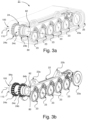
- Fig. 3a schematically illustrates a perspective view of a track assembly 21 comprising a drive arrangement according to an embodiment of the present invention
- fig. 3b schematically illustrates a perspective view of the track assembly in fig. 3a without the endless track 25
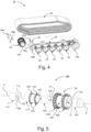
- fig. 4 schematically illustrates a partly exploded perspective view of the track assembly 21 in fig. 3a .
- the track assembly 21 is together with another track assembly forming a track assembly pair as described with reference to fig. 1 and 2 arranged to drive a tracked vehicle/tracked vehicle unit.
- the track assembly 21 comprises a track support beam 22, which is here constituted by a skid beam.
- the track assembly further comprises a set of road wheels 23, 23a, a drive wheel 24, and an endless track 25.
- Said endless track 25 is arranged to run over the drive wheel 24 and said set of road wheels 23, 23a.
- the track assembly 21 has one drive wheel but may have more than one drive wheel.
- Said set of road wheels 23, 23a and the drive wheel 24 are arranged to be rotatably supported by said track support beam 22 in a suitable manner.
- Said set of road wheels 23, 23a are arranged in a pair configuration, meaning that the respective road wheels 23, 23a in each pair configuration is arranged on opposite sides of said track support beam 22.
- the support wheel 23a arranged at the very rear of the track support beam 22 also has a track tension wheel function and is constituted by a tension wheel.
- the track support beam 22 comprises a front element 22a comprising a front fastening point and a rear element 22b comprising a rear fastening point, said elements 22a, 22b being arranged to receive suspension means such as e.g. a bogie arrangement in accordance with fig. 1 and 2 , pendulum arms or other suitable arrangement for suspension for allowing relative movement of tracks assembly relative to vehicle body.
- suspension means such as e.g. a bogie arrangement in accordance with fig. 1 and 2 , pendulum arms or other suitable arrangement for suspension for allowing relative movement of tracks assembly relative to vehicle body.
- Said front element 22a and rear element 22b constitute integrated parts of said track support beam 22 arranged between two longitudinal beams of the track support beam 22 and arranged to project from an upper portion of said longitudinal beams within the circumference of the endless track surrounding the track support beam 22.
- the drive wheel 24 comprises a first gear portion 24a and a second gear portion 24b, said gear portions 24a, 24b being arranged to engage with said endless track 25 for rotating said endless track 25 for propulsion of the tracked vehicle.
- the drive wheel 24 comprises a housing portion 24c.
- the first gear portion 24a and second gear portion 24b are arranged to surround said housing portion 24c.
- the first gear portion 24a and second gear portion 24b are protrudingly arranged about said housing portion 24c.
- the first gear portion 24a and second gear portion 24b are coaxially aligned and laterally separated from each other.
- the track assembly 21 comprises a drive arrangement 100.
- the drive arrangement 100 comprises a motor for operating said drive wheel 24.
- the drive arrangement 100 further comprises a transmission device for transferring torque from said motor to said drive wheel 24 and a brake member for braking the drive wheel.
- said drive wheel 24 with said drive arrangement 100 constitutes a drive unit.
- the drive wheel 24 with said drive arrangement 100 comprising said motor thus constitutes a motorised drive wheel for operating a tracked vehicle. Said drive arrangement 100 is described in more detail with reference to fig. 5 .
- the drive arrangement 100 is arranged in connection to the drive wheel 24 so that it at least partly is accommodated within the periphery of the drive wheel 24 in the direction transversal to a main direction of extension of the track assembly.
- At least one of said motor, transmission device and said brake member of the drive arrangement 100 is arranged in connection to the drive wheel so that it at least partly is accommodated within the periphery of the drive wheel in the direction transversal to a main direction of extension of the track assembly.
- the housing portion 24c of said drive wheel 24 is arranged to receive said drive arrangement 100 so that it at least partly is accommodated within the housing portion 24c of the drive wheel 24.
- the drive arrangement 100 is arranged in connection to the drive wheel 24 such that a motor axle essentially coaxially coincides with the centre axis Z of the drive wheel 24, which is illustrated in e.g. fig. 5 .
- the track assembly 21 comprises a fastening arrangement 80 arranged relative to said track support beam 22.
- the fastening arrangement 80 is arranged to support said drive arrangement 100.
- the fastening arrangement 80 comprises according to this embodiment a fork configuration 82 for supporting said drive wheel 24 and drive arrangement 100.
- Non rotating parts of said drive arrangement 100 are arranged to be fixedly attached to said fork configuration 82.
- the fork configuration 82 may also be denoted claw configuration.
- the fork configuration 82 may have any suitable shape for supporting non rotating parts of said drive arrangement 100.
- the fork configuration may have supporting arms or claws having a supporting function and facilitating attachment of non-rotating parts of said drive arrangement 100.
- Said fork configuration 82 of said fastening arrangement 80 is according to this embodiment an integrated part of said track support beam 22.
- Said fork configuration 82 is arranged at an end portion of said track support beam 22 for supporting said drive wheel 24 and hence drive arrangement 100.
- Said fork configuration 82 comprises according to this embodiment a right claw member 82a and a left claw member 82b.
- Said fork configuration 82 comprises a transversal portion 82c from which said right claw member 82a and a left claw member 82b are arranged to project.
- Said fastening arrangement 80 comprises according to this embodiment clamping members 84a, 84b for clamping said drive arrangement 100 to said fork configuration 82.
- Said fastening arrangement 80 comprises a right clamping member 84a and a left clamping member 84b.
- Said right clamping member 84a is arranged to clamp said drive arrangement 100 to said right claw member 82a of said fork configuration 82 in connection to the right side of said drive wheel 24 and said left clamping member 84b is arranged to clamp said drive arrangement 100 to said left claw member 82b of said fork configuration 82 in connection to the left side of said drive wheel 24.
- the drive arrangement 100 is, in the direction essentially perpendicular to the longitudinal direction and the transversal direction of the endless track 25, arranged within the periphery of the endless track 25.
- the transversal extension of the drive arrangement 100 is within the width of the endless track 25.
- Fig. 5 schematically illustrates an exploded perspective view of the drive arrangement 100 according to an embodiment of the present invention
- fig. 6 schematically illustrates a cross sectional view of the drive arrangement 100 in fig. 5 .
- the drive arrangement 100 comprises a motor 110 for operating said drive wheel 24.
- Said motor 110 may be an electric motor or a hydraulic motor.
- Said motor comprises a rotatable motor axle 112.
- Said motor 110 comprises a rotor 110a for providing a rotational movement of said motor axle 112.
- Said motor comprises a stator 110b configured to be fixedly attached to said track support beam 22.
- Said rotor is arranged to provide a rotational movement of said motor axle 112 relative to the stator for said operation of the drive wheel 24.
- Said fastening arrangement 80 shown e.g. in fig. 3a and 3b , is according to an embodiment arranged to support said motor 110.
- Said stator 110b of the motor 110 is according to an embodiment configured to be fixedly arranged to said fastening arrangement 80.
- Said fork configuration 82 of said fastening arrangement 80 shown e.g. in fig. 3a and 3b , is according to an embodiment arranged to support said motor 110.
- Said stator 110b of the motor 110 is according to an embodiment configured to be fixedly arranged to said fork configuration 82 of said fastening arrangement 80.
- Said drive arrangement 100 comprises according to this embodiment a motor housing 114 for housing said motor 110.
- Said stator 110b is configured to be fixedly arranged in said motor housing 114.
- Said stator 110b of the motor 110 is according to an embodiment configured to be fixedly arranged to said fork configuration 82 of said fastening arrangement 80 via said motor housing.
- Said motor housing 114 is according to an embodiment configured to be fixedly arranged to said fork configuration 82 of said fastening arrangement 80.
- Said drive arrangement 100 comprises a bearing configuration 120.
- Said bearing configuration 120 is arranged to allow the drive wheel 24 to rotate relative to the stator 110b of the motor 110.
- the bearing configuration 120 is configured to be arranged about said motor housing 114.
- the bearing configuration 120 is according to this embodiment a rolling bearing configuration.
- the bearing configuration 120 comprises according to this embodiment a rolling bearing configuration with a first rolling bearing 122 and a second rolling bearing 124.
- Said first rolling bearing 122 and a second rolling bearing 124 are arranged around the periphery of said motor housing 114 at a distance from each other.
- Said first rolling bearing 122 and a second rolling bearing 124 are coaxially aligned and laterally separated from each other.
- the drive arrangement 100 further comprises a transmission device for transferring torque from said motor to said drive wheel 24.
- the transmission device 130 may be any suitable transmission device for transferring torque from said motor 110 to said drive wheel 24.
- the transmission device 130 comprises according to an embodiment a planetary gear and a transmission axle 132, 134 for said torque transfer.
- Said transmission axle 132, 134 comprises an input axle 132 configured to be coupled to said motor axle 112 and an output axle 134 configured to be coupled to said drive wheel 24 for torque transfer to said drive wheel 24.
- the drive arrangement 100 further comprises a brake member 140 for braking the drive wheel.
- the brake member 140 may be any suitable brake member such as one or more drum brakes or one or more disc brakes.
- the drive wheel 24 has a centre axis Z.
- the housing portion 24c of the drive wheel 24 has according to this embodiment a cylindrical configuration with openings O1, O2 at the respective ends and an internal space S.
- the housing 24c of said drive wheel 24 has a ring-shaped cross section.
- the housing 24c of said drive wheel 24 is according to this embodiment arranged to receive said drive arrangement 100.
- Said drive arrangement 100 is arranged to at least partly be housed in said housing portion 24c of said drive wheel 24.
- the housing 24c of said drive wheel 24 is according to this embodiment arranged to receive said motor 110.
- Said motor 110 is arranged to at least partly be housed in said housing portion 24c of said drive wheel 24.
- the housing 24c of said drive wheel 24 is according to this embodiment arranged to receive said bearing configuration 120.
- Said bearing configuration 120 is arranged to at least partly be housed in said housing portion 24c of said drive wheel 24.
- the housing 24c of said drive wheel 24 is according to this embodiment arranged to receive said transmission device 130.
- Said transmission device 130 is arranged to at least partly be housed in said housing portion 24c of said drive wheel 24.
- the drive wheel 24 thus has an opening O1, O2 into an internal space S of said drive wheel 24 for receiving said motor 110.
- Said internal space of the drive wheel 24 has a transversal extension relative to the main direction of extension of the track assembly.
- Said motor 110 is arranged in connection to the drive wheel 24 inside said internal space S of said drive wheel 24 or next to said drive wheel 24 so that the motor 110 at least partly is accommodated within the periphery of the drive wheel 24 in the direction transversal to a main direction of extension of the track assembly 21, see fig. 3a , so as to allow said motor 110 to move relative to said vehicle body together with said track assembly 21.
- the motor 110 is according to an embodiment arranged to at least partly extend through said opening O1 of said internal space S of said drive wheel 24.
- Said bearing configuration 120 is configured to be arranged between said motor housing 114 and said housing 24c of said drive wheel 24.
- said first rolling bearing 122 and a second rolling bearing 124 are arranged between said motor housing 114 and said housing 24c of said drive wheel 24.
- Said bearing configuration 120 is configured to be arranged between said motor housing 114 and said housing 24c of said drive wheel 24 so as to allow rotational movement of said housing 24c of said drive wheel 24 relative to said motor housing 114.
- said bearing configuration 120 is configured to be arranged between said motor housing 114 and said housing 24c of said drive wheel 24 so as to allow rotational movement of said first gear portion 24a and a second gear portion 24b of said drive wheel 24 relative to said stator 110b of said motor 110.
- Said motor axle 112 is operably connected to said housing 24c of said drive wheel 24 for rotating said drive wheel 24, see fig. 6 .
- Said motor axle 112 is configured to transfer torque to said housing 24c.
- Said motor axle 112 is operably connected to said housing 24c of said drive wheel 24 via said transmission device 130 for rotating said drive wheel 24, see fig. 6 .
- Said rotor 110a of the motor 110 is arranged to transfer torque to said housing 24c for rotating said housing 24c and hence said drive wheel 24.
- Said rotor 110a of the motor 110 is arranged to transfer torque to said housing 24c via said transmission device 130 for rotating said housing 24c and hence said drive wheel 24.
- the stator 110b of said motor 110 is configured to be fixedly attached to said fastening arrangement 80, fastening arrangement 80 being shown in e.g. fig. 3b and fig. 4 .
- the motor housing 114 is configured to be fixedly attached to said fastening arrangement 80.
- the brake member 140 comprises a stator part configured to be fixedly attached to said fastening arrangement 80 and a rotor part.
- Said right clamping member 84a is arranged to clamp said motor housing 110 of said drive arrangement 100 to said right claw member 82a of said fork configuration 82 in connection to the right side of said drive wheel 24.
- Said left clamping member 84b is arranged to clamp the stator part of said brake member 140 of said drive arrangement 100 to said left claw member 82b of said fork configuration 82 in connection to the left side of said drive wheel 24.
- Said brake member 140 may be any suitable brake member.
- Said brake member 140 is according to an embodiment a drum brake.
- Said brake member 140 is according to an embodiment a disc brake.
- Said brake member 140 is according to an embodiment a wet multi disc brake.
- Said brake member 140 is according to an embodiment a dry multi disc brake.
- said drive wheel 24 and said drive arrangement 100 constitute a drive unit of said track assembly.
- the drive unit constitutes a motorized drive wheel.
Landscapes
- Engineering & Computer Science (AREA)
- Chemical & Material Sciences (AREA)
- Combustion & Propulsion (AREA)
- Transportation (AREA)
- Mechanical Engineering (AREA)
- Arrangement Or Mounting Of Propulsion Units For Vehicles (AREA)
- Hybrid Electric Vehicles (AREA)
- Arrangement Of Transmissions (AREA)
Description
- The present invention relates to a tracked vehicle according to the preamble of claim 1.
- Tracked vehicles normally comprise a pair of track assemblies, where each track assembly of the pair of track assemblies comprises a track support beam, a drive wheel, a plurality of road wheels and an endless track running over the drive wheel and said plurality of road wheels. Said drive wheel and said plurality of road wheels are rotatably secured to said track support beam. Said drive wheel is arranged to drive said endless track running over said drive wheel and said set of road wheels so as to propel the tracked vehicle. Such a tracked vehicle comprises a drive unit comprising said track assemblies and drive means for driving said drive wheels of the tracked vehicle, where said drive means may comprise any suitable engine/motor.
-
WO2014182216A1 discloses a tracked vehicle having a track assembly comprising a track support beam configured to support a plurality of road wheels and a drive wheel. Said track support beam is supported by a vehicle chassis of the tracked vehicle by means of a suspension device allowing relative movement between the track support beam and the vehicle chassis. The tracked vehicle comprises a drive unit comprising said track support beam an electric motor which is connected to said at least one drive wheel and integrated in said track support beam in a longitudinal direction of said track support beam, said electric motor being be fixedly arranged to said track support beam. Hereby driving of the respective drive wheel of the vehicle is facilitated. Although a relatively compact drive unit with low weight may be obtained, the electric motor still occupies space for other relevant components such as bushings and fastening arrangements for road wheel arms and spring arrangements. -
US 2007/029878 A1 discloses a tracked vehicle comprising a vehicle body and a track assembly pair according the preamble of independent claim 1. - Further relevant examples of tracked vehicles are known from
WO 2014/182235 A1 andUS 2009/078528 A1 . - Consequently there is a need to present improvements for track assemblies for tracked vehicles.
- An object of the present invention is to provide a tracked vehicle with a track assembly pair for driving the vehicle which facilitates high operational reliability and efficiency in which motor for said operation provides a compact solution.
- These and other objects, apparent from the following description, are achieved by a tracked vehicle which is of the type stated by way of introduction and which in addition exhibits the features recited in the characterising clause of the appended claim 1. Preferred embodiments of the tracked vehicle are defined in appended dependent claims.
- Specifically an object of the invention is achieved by a tracked vehicle comprising a vehicle body and a track assembly pair, said track assembly pair being arranged to suspendedly support said vehicle body allowing relative movement between said vehicle body and each track assembly of said track assembly pair, each track assembly comprising a track support beam configured to support a plurality of road wheels, a drive wheel, and a motor for operating said drive wheel, an endless track being disposed around said road wheels and drive wheel, said motor being fixedly arranged to said track support beam, wherein said motor is arranged in connection to the drive wheel such that a motor axle essentially coaxially coincides with the centre axis of the drive wheel.
- By thus arranging said motor in connection to the drive wheel such that a motor axle essentially coaxially coincides with the centre axis of the drive wheel and where relative movement between said vehicle body and each track assembly of said track assembly pair by means of suspendedly supporting said vehicle body via e.g. a suspension arrangement is allowed, high operational reliability and efficiency of said tracked vehicle is facilitated in which motor for said operation provides a compact solution.
- By thus arranging said motor in connection to the drive wheel such that a motor axle essentially coaxially coincides with the centre axis of the drive wheel a compact solution for said motor arranged in said track assemblies is facilitated, wherein space is made available e.g. in connection to said track support beam for suspension arrangements.
- The object of the invention is further achieved in that said motor is comprised in a drive arrangement, said drive arrangement further comprising a transmission device for transferring torque from said motor to said drive wheel and a brake member for braking the drive wheel, wherein at least one of said transmission device and said brake member is arranged in connection to the drive wheel so that it at least partly is accommodated within the periphery of the drive wheel in the direction transversal to a main direction of extension of the track assembly.
- According to the invention, said fastening arrangement comprises a claw configuration for supporting said drive wheel and drive arrangement, wherein non-rotating parts of said drive arrangement are arranged to be fixedly attached to said claw configuration, wherein said claw configuration comprises a right claw member and a left claw member for said attachment of said non-rotating parts, and a transversal portion from which said right claw member and a left claw member are arranged to project.
- The tracked vehicle may comprise one or more tracked vehicle units. The tracked vehicle comprises according to an embodiment more than one tracked vehicle unit, said vehicle units being articulately connected to each other. The tracked vehicle is according to an embodiment a tracked articulated vehicle. The tracked vehicle thus comprises opposite track assemblies, a right track assembly and the opposite track assembly constituting a left track assembly, said right and left track assemblies constituting said track assembly pair. For a tracked vehicle comprising more than one vehicle unit, each vehicle unit comprises such a track assembly pair.
- Each track support beam is further arranged to support a tension wheel.
- According to an embodiment of the tracked vehicle said motor is arranged in connection to the drive wheel so that the motor at least partly is accommodated within the periphery of the drive wheel in the direction transversal to a main direction of extension of the track assembly so as to allow said motor to move relative to said vehicle body together with said track assembly. Hereby a compact arrangement of the motor of the track assembly is provided making space available in the track assembly in connection to said track support beam. Said motor is arranged in connection to the drive wheel inside an internal space of said drive wheel or next to said drive wheel so that the motor at least partly is accommodated within the periphery of the drive wheel in the direction transversal to a main direction of extension of the track assembly so as to allow said motor to move relative to said vehicle body together with said track assembly. The drive wheel has an opening into said internal space of said drive wheel for receiving said motor. Said internal space has a ring-shaped cross section. Said internal space of the drive wheel has a transversal extension relative to the main direction of extension of the track assembly. The motor is according to an embodiment arranged to at least partly extend through said opening of said internal space of said drive wheel.
- According to an embodiment of the tracked vehicle the motor in the direction essentially perpendicular to the longitudinal direction and the transversal direction of the endless track is arranged within the periphery of the endless track. Hereby the motor is efficiently protected within the track assembly. According to an embodiment of the tracked vehicle the motor is accommodated within said drive wheel within the outer contours of the drive wheel. Hereby the motor is efficiently protected by the drive wheel.
- As mentioned above and in accordance with the object of the invention, said motor is comprised in a drive arrangement, said drive arrangement further comprising a transmission device for transferring torque from said motor to said drive wheel and a brake member for braking the drive wheel, wherein at least one of said transmission device and said brake member is arranged in connection to the drive wheel so that it at least partly is accommodated within the periphery of the drive wheel in the direction transversal to a main direction of extension of the track assembly. By thus providing a drive arrangement and also arranging e.g. said transmission device in connection to the drive wheel so that it at least partly is accommodated within the periphery of the drive wheel a compact solution for said drive arrangement arranged in said track assemblies is facilitated, wherein space is made available e.g. in connection to said track support beam for suspension arrangements.
- The transmission device may be any suitable transmission device for transferring torque from said motor to said drive wheel. The transmission device comprises according to an embodiment a planetary gear and a transmission axle with an input axle configured to be coupled to said motor axle and an output axle configured to be coupled to said drive wheel for torque transfer to said drive wheel.
- According to an embodiment of the tracked vehicle said motor is an electric motor or a hydraulic motor, said motor comprising a stator and a rotor for providing a rotational movement of said motor axle relative to the stator for said operation of the drive wheel.
- According to an embodiment of the tracked vehicle the stator of the motor is fixedly arranged relative to said track support beam via a fastening arrangement and the rotor of the motor is arranged to drive said drive wheel. Hereby efficient operation of said tracked vehicle is obtained.
- The rotor of the motor is thus arranged to drive said drive wheel via said transmission device. The motor is according to an embodiment configured to be in a motor housing wherein said stator is fixedly arranged in said motor housing.
- According to an embodiment said drive arrangement comprises a bearing configuration arranged to allow the drive wheel to rotate relative to the stator of the motor. The bearing configuration comprises according to an embodiment a rolling bearing.
- As mentioned above and in accordance with the invention, said fastening arrangement comprises a claw configuration for supporting said drive wheel and drive arrangement, wherein non-rotating parts of said drive arrangement are arranged to be fixedly attached to said claw configuration, wherein said claw configuration comprises a right claw member and a left claw member for said attachment of said non-rotating parts, and a transversal portion from which said right claw member and a left claw member are arranged to project. By thus providing a fastening arrangement with a claw configuration efficient support of drive wheel and fixation of stator of motor is facilitated, thus facilitating a compact arrangement for the motor and hence also the drive arrangement so that space is made available in the track assembly. The claw configuration may also be denoted fork configuration. The fork configuration may have any suitable shape for supporting non rotating parts of said drive arrangement. The fork configuration may have supporting arms or claws having a supporting function and facilitating attachment of non-rotating parts of said drive arrangement. Said fork configuration is thus arranged to support said drive arrangement. Said stator of the motor is arranged to be fixedly attached to said fork configuration. Said stator of the motor is according to an embodiment arranged to be fixedly attached to said fork configuration via said motor housing. Non rotating parts of said drive arrangement are arranged to be fixedly attached to said fork configuration.
- Said fork configuration of said fastening arrangement is according to an embodiment an integrated part of said track support beam. Said fork configuration may be attached to said track support beam by means of any suitable attachment means such as e.g. by a welding joint. Said fork configuration is arranged at an end portion of said track support beam for supporting said drive wheel and hence drive arrangement and motor.
- Said fork configuration comprises a right claw member and a left claw member. Said fork configuration comprises a transversal portion from which said right claw member and a left claw member are arranged to project.
- According to an embodiment of the tracked vehicle said fastening arrangement comprises clamping members for clamping said stator to said fork configuration. By thus providing clamping members the motor will be efficiently fixed to said track support beam via said fork configuration and still allowing access to the motor and thus drive arrangement by removal of said clamping members.
- Said clamping members are thus configured to be removably attached to said fork configuration for lamping said stator to said fork configuration.
- According to an embodiment of the tracked vehicle said tracked vehicle is a forestry machine, such as a forwarder.
- A better understanding of the present invention will be had upon the reference to the following detailed description when read in conjunction with the accompanying drawings, wherein like reference characters refer to like parts throughout the several views, and in which:
-
Fig. 1 schematically illustrates a perspective view of a tracked vehicle comprising drive unit pairs according to an embodiment of the present invention; -
Fig. 2 schematically illustrates a side view of a tracked vehicle according to an embodiment of the present invention; -
Fig. 3a schematically illustrates a perspective view of a track assembly comprising a drive arrangement according to an embodiment of the present invention; -
Fig. 3b schematically illustrates a perspective view of the track assembly infig. 3a without the endless track; -
Fig. 4 schematically illustrates a partly exploded perspective view of the track assembly infig. 3a ; -
Fig. 5 schematically illustrates an exploded perspective view of a drive arrangement comprising a motor according to an embodiment of the present invention; and -
Fig. 6 schematically illustrates a cross sectional view of the drive arrangement infig. 5 . - Hereinafter the term "track support beam" refers to a structural element arranged to support ground-engaging means such as e.g. an endless track as well as drive wheel and road wheels.
- Herein the term "skid beam" refers to an example of a track support beam.
- Hereinafter the term "track assembly" refers to a unit of the tracked vehicle comprising track support beam, drive wheel and road wheels as well as a circumferential endless track, which unit is arranged to comprise ground-engaging means and configured to propel the vehicle and thus form at least part of a drive unit of the tracked vehicle.
- Hereinafter the term "track assembly pair" refers to opposite track assemblies of a vehicle unit of the vehicle, one track assembly constituting a right track assembly and the opposite track assembly constituting a left track assembly.
- Hereinafter the term "articulated vehicle" refers to a vehicle with at least a front and a rear vehicle unit which are pivotable relative to each other about at least one joint.
- Hereinafter the term "vehicle body" refers to any structure of a vehicle configured to support track assemblies of a tracked vehicle and may comprise or constitute the vehicle chassis. The term "vehicle body" may refer to a vehicle frame, one or more beams or the like.
- Hereinafter the term "fork configuration" refers to any suitable fork-like or claw like configuration for supporting non-rotating parts of a drive arrangement comprising a motor, and may have supporting arms or claws having a supporting function and facilitating attachment of non-rotating parts of said drive arrangement.
- Referring to
fig. 1 , a trackedvehicle 10 according to the present invention is illustrated, provided with afront vehicle unit 11 and arear vehicle unit 12. - Each of the front and rear vehicle unit comprises a
track assembly pair 20. Saidtrack assembly pair 20 is constituted by or comprised of a drive unit pair. Saidtrack assembly pair 20 comprises twotrack assemblies 21 arranged on opposite sides of thevehicle 10. Therespective track assembly 21 is constituted by or comprised of a drive unit. Therespective track assembly 21 is constituted by a driving track assembly and is arranged for propulsion of the vehicle. The respectivetrack assembly pair 20 is connected to anintermediate vehicle body front vehicle unit 11 comprises avehicle body 30 and therear vehicle unit 12 comprises avehicle body 32. - Each of the front and
rear vehicle unit respective track assembly 21. Therespective track assembly 21 of therespective vehicle unit respective vehicle body track assembly pair 20 is thus arranged to suspendedly support saidvehicle body vehicle body track assembly 21 of saidtrack assembly pair 20. Saidtrack assembly pair 20 is thus arranged to suspendedly support saidvehicle body - The suspension device S of the
respective vehicle unit track assembly 21 may comprise any suitable arrangement for allowing relative movement between saidvehicle body track assembly 21 of saidtrack assembly pair 20. - The suspension device S according to the example in
fig. 1 comprises abogie arrangement 50. Thebogie arrangement 50 is configured to be rotatably attached to thevehicle body respective vehicle unit vehicle 11, about an axis of rotation transversal to the longitudinal extension of saidtrack assembly 21 and attached to saidtrack support beam 22 in connection to two fastening points so that thetrack support beam 22 is allowed to rotate in a rotational plane extending along the longitudinal extension of saidtrack support beam 22 about said axis of rotation. Said bogie arrangement is rotatably attached to said vehicle body at a single fastening point for said axis of rotation. Therespective bogie arrangement 50 comprises bogie arms pivotably connected to each other and rotatably attached to a respective fastening point of said two fastening points of saidtrack support beam 22 so that said bogie arms are allowed to move relative to each other in said rotational plane. Saidbogie arrangement 50 is thus an articulated bogie arrangement. - The suspension device S according to the example in
fig. 1 comprises or constitutes a track assembly suspension configuration. - Said suspension device S further comprises a
suspension configuration 60 which according to this embodiment is constituted by a gashydraulic suspension configuration 60. The gashydraulic suspension configuration 60 is arranged for damping the movement of saidbogie arrangement 50 and hence the movement of thetrack assembly 21 relative to thevehicle body - The gas
hydraulic suspension configuration 60 is further arranged for controlling the position of thebogie arrangement 50 and hence the position of thetrack assembly 21 relative to thevehicle body - Said gas
hydraulic suspension configuration 60 comprises according to this embodiment a pair ofhydraulic cylinders respective track assembly 21 of the trackedvehicle 10. - Each
track assembly 21 comprises atrack support beam 22, a set ofroad wheels drive wheel 24, and anendless track 25. Saidendless track 25 is arranged to run over thedrive wheel 24 and said set ofroad wheels - Each
track assembly 21 comprises adrive arrangement 100 comprising a motor for operating saiddrive wheel 24. Saiddrive arrangement 100 further comprises a transmission device for transferring torque from said motor to saiddrive wheel 24 and a brake member for braking the drive wheel. According to an embodiment saiddrive wheel 24 is also comprised in saiddrive arrangement 100. Saiddrive arrangement 100 is described in more detail with reference tofig. 3a-b ,4 and 5 . - The
drive arrangement 100 is arranged in connection to the drive wheel so that it at least partly is accommodated within the periphery of the drive wheel in the direction transversal to a main direction of extension of the track assembly. At least one of said motor, transmission device and said brake member of thedrive arrangement 100 is arranged in connection to the drive wheel so that it at least partly is accommodated within the periphery of the drive wheel in the direction transversal to a main direction of extension of the track assembly. - The
drive arrangement 100 is arranged in connection to thedrive wheel 24 such that a motor axle essentially coaxially coincides with the centre axis of thedrive wheel 24, which is illustrated in e.g.fig. 5 . - Said
vehicle body respective vehicle unit - According to this configuration of the
vehicle 10, thevehicle body 30 of thefront vehicle unit 11 is arranged to support avehicle cabin 15 and a power supply, such as an internal combustion engine, where the internal combustion engine according to one embodiment is constituted by a diesel engine. - According to this configuration of the
vehicle 10, thevehicle body 32 of therear vehicle unit 12 is arranged to support aU-beam configuration 42 or aload beam configuration 42 for supporting timber and aloading gate 43. Thevehicle body 32 of therear vehicle unit 12 is according to this embodiment also arranged to support acrane 44 for loading/unloading of timber. - The exemplified
vehicle 10 is a tracked forestry vehicle in the form of a forwarder intended to transport timber from a harvesting site to a collection site. Thevehicle 10 according to the present invention may be constituted by any suitable tracked vehicles. According to one embodiment, thevehicle 10 is a harvester intended for cutting timber. - The exemplified
vehicle 10 may according to an embodiment be a diesel-electric driven vehicle comprising saiddrive arrangement 100. Thevehicle 10 may according to one alternative have any suitable power supply involving saiddrive arrangement 100 for the propulsion of thevehicle 10. Thevehicle 10 is according to one alternative a hybrid-powered vehicle involving saiddrive arrangement 100. Thevehicle 10 is according to one alternative electrically driven involving saiddrive arrangement 100, where power according to one alternative is supplied by means of an energy storage device such as a battery unit, fuel cell or capacitor unit. -
Fig. 2 schematically illustrates a side view of a trackedvehicle 11 according to an embodiment of the present invention. The trackedvehicle 11 essentially corresponds to thevehicle unit 11 infig. 1. Fig. 2 schematically illustrates a side view of the trackedvehicle 11 with a suspension device S where thevehicle body 30 is raised relative to thetrack assembly 21 and hence thedrive arrangement 100 with the motor. Said gas hydraulic suspension configuration is controlled such that front and rearhydraulic cylinders vehicle body 30 is raised relative to the track assembly, saidbogie arm configuration 50 allowing said raising of thevehicle body 30. -
Fig. 3a schematically illustrates a perspective view of atrack assembly 21 comprising a drive arrangement according to an embodiment of the present invention,fig. 3b schematically illustrates a perspective view of the track assembly infig. 3a without theendless track 25, andfig. 4 schematically illustrates a partly exploded perspective view of thetrack assembly 21 infig. 3a . - The
track assembly 21 is together with another track assembly forming a track assembly pair as described with reference tofig. 1 and 2 arranged to drive a tracked vehicle/tracked vehicle unit. - The
track assembly 21 comprises atrack support beam 22, which is here constituted by a skid beam. The track assembly further comprises a set ofroad wheels drive wheel 24, and anendless track 25. Saidendless track 25 is arranged to run over thedrive wheel 24 and said set ofroad wheels track assembly 21 has one drive wheel but may have more than one drive wheel. - Said set of
road wheels drive wheel 24 are arranged to be rotatably supported by saidtrack support beam 22 in a suitable manner. Said set ofroad wheels respective road wheels track support beam 22. Thesupport wheel 23a arranged at the very rear of thetrack support beam 22 also has a track tension wheel function and is constituted by a tension wheel. - The
track support beam 22 comprises afront element 22a comprising a front fastening point and arear element 22b comprising a rear fastening point, saidelements fig. 1 and 2 , pendulum arms or other suitable arrangement for suspension for allowing relative movement of tracks assembly relative to vehicle body. Saidfront element 22a andrear element 22b constitute integrated parts of saidtrack support beam 22 arranged between two longitudinal beams of thetrack support beam 22 and arranged to project from an upper portion of said longitudinal beams within the circumference of the endless track surrounding thetrack support beam 22. - The
drive wheel 24 comprises afirst gear portion 24a and asecond gear portion 24b, saidgear portions endless track 25 for rotating saidendless track 25 for propulsion of the tracked vehicle. - The
drive wheel 24 comprises ahousing portion 24c. Thefirst gear portion 24a andsecond gear portion 24b are arranged to surround saidhousing portion 24c. Thefirst gear portion 24a andsecond gear portion 24b are protrudingly arranged about saidhousing portion 24c. Thefirst gear portion 24a andsecond gear portion 24b are coaxially aligned and laterally separated from each other. - The
track assembly 21 comprises adrive arrangement 100. Thedrive arrangement 100 comprises a motor for operating saiddrive wheel 24. Thedrive arrangement 100 further comprises a transmission device for transferring torque from said motor to saiddrive wheel 24 and a brake member for braking the drive wheel. According to an embodiment saiddrive wheel 24 with saiddrive arrangement 100 constitutes a drive unit. Thedrive wheel 24 with saiddrive arrangement 100 comprising said motor thus constitutes a motorised drive wheel for operating a tracked vehicle. Saiddrive arrangement 100 is described in more detail with reference tofig. 5 . - The
drive arrangement 100 is arranged in connection to thedrive wheel 24 so that it at least partly is accommodated within the periphery of thedrive wheel 24 in the direction transversal to a main direction of extension of the track assembly. At least one of said motor, transmission device and said brake member of thedrive arrangement 100 is arranged in connection to the drive wheel so that it at least partly is accommodated within the periphery of the drive wheel in the direction transversal to a main direction of extension of the track assembly. As described in more detail with reference tofig. 5 thehousing portion 24c of saiddrive wheel 24 is arranged to receive saiddrive arrangement 100 so that it at least partly is accommodated within thehousing portion 24c of thedrive wheel 24. - The
drive arrangement 100 is arranged in connection to thedrive wheel 24 such that a motor axle essentially coaxially coincides with the centre axis Z of thedrive wheel 24, which is illustrated in e.g.fig. 5 . - The
track assembly 21 comprises afastening arrangement 80 arranged relative to saidtrack support beam 22. Thefastening arrangement 80 is arranged to support saiddrive arrangement 100. - As shown e.g. in
fig. 4 thefastening arrangement 80 comprises according to this embodiment afork configuration 82 for supporting saiddrive wheel 24 and drivearrangement 100. - Non rotating parts of said
drive arrangement 100 are arranged to be fixedly attached to saidfork configuration 82. Thefork configuration 82 may also be denoted claw configuration. Thefork configuration 82 may have any suitable shape for supporting non rotating parts of saiddrive arrangement 100. The fork configuration may have supporting arms or claws having a supporting function and facilitating attachment of non-rotating parts of saiddrive arrangement 100. - Said
fork configuration 82 of saidfastening arrangement 80 is according to this embodiment an integrated part of saidtrack support beam 22. Saidfork configuration 82 is arranged at an end portion of saidtrack support beam 22 for supporting saiddrive wheel 24 and hence drivearrangement 100. - Said
fork configuration 82 comprises according to this embodiment aright claw member 82a and a left claw member 82b. Saidfork configuration 82 comprises atransversal portion 82c from which saidright claw member 82a and aleft claw member 82b are arranged to project. - Said
fastening arrangement 80 comprises according to thisembodiment clamping members drive arrangement 100 to saidfork configuration 82. Saidfastening arrangement 80 comprises aright clamping member 84a and a left clamping member 84b. Said right clampingmember 84a is arranged to clamp saiddrive arrangement 100 to saidright claw member 82a of saidfork configuration 82 in connection to the right side of saiddrive wheel 24 and said left clampingmember 84b is arranged to clamp saiddrive arrangement 100 to saidleft claw member 82b of saidfork configuration 82 in connection to the left side of saiddrive wheel 24. - As can be seen in
fig. 3a thedrive arrangement 100 is, in the direction essentially perpendicular to the longitudinal direction and the transversal direction of theendless track 25, arranged within the periphery of theendless track 25. The transversal extension of thedrive arrangement 100 is within the width of theendless track 25. -
Fig. 5 schematically illustrates an exploded perspective view of thedrive arrangement 100 according to an embodiment of the present invention andfig. 6 schematically illustrates a cross sectional view of thedrive arrangement 100 infig. 5 . - The
drive arrangement 100 comprises amotor 110 for operating saiddrive wheel 24. Saidmotor 110 may be an electric motor or a hydraulic motor. Said motor comprises arotatable motor axle 112. Saidmotor 110 comprises arotor 110a for providing a rotational movement of saidmotor axle 112. Said motor comprises astator 110b configured to be fixedly attached to saidtrack support beam 22. Said rotor is arranged to provide a rotational movement of saidmotor axle 112 relative to the stator for said operation of thedrive wheel 24. - Said
fastening arrangement 80, shown e.g. infig. 3a and 3b , is according to an embodiment arranged to support saidmotor 110.Said stator 110b of themotor 110 is according to an embodiment configured to be fixedly arranged to saidfastening arrangement 80. Saidfork configuration 82 of saidfastening arrangement 80, shown e.g. infig. 3a and 3b , is according to an embodiment arranged to support saidmotor 110.Said stator 110b of themotor 110 is according to an embodiment configured to be fixedly arranged to saidfork configuration 82 of saidfastening arrangement 80. - Said
drive arrangement 100 comprises according to this embodiment amotor housing 114 for housing saidmotor 110.Said stator 110b is configured to be fixedly arranged in saidmotor housing 114.Said stator 110b of themotor 110 is according to an embodiment configured to be fixedly arranged to saidfork configuration 82 of saidfastening arrangement 80 via said motor housing. Saidmotor housing 114 is according to an embodiment configured to be fixedly arranged to saidfork configuration 82 of saidfastening arrangement 80. - Said
drive arrangement 100 comprises abearing configuration 120. Said bearingconfiguration 120 is arranged to allow thedrive wheel 24 to rotate relative to thestator 110b of themotor 110. The bearingconfiguration 120 is configured to be arranged about saidmotor housing 114. The bearingconfiguration 120 is according to this embodiment a rolling bearing configuration. The bearingconfiguration 120 comprises according to this embodiment a rolling bearing configuration with a first rolling bearing 122 and a second rolling bearing 124. Said first rollingbearing 122 and a second rolling bearing 124 are arranged around the periphery of saidmotor housing 114 at a distance from each other. Said first rollingbearing 122 and a second rolling bearing 124 are coaxially aligned and laterally separated from each other. - The
drive arrangement 100 according to this embodiment further comprises a transmission device for transferring torque from said motor to saiddrive wheel 24. Thetransmission device 130 may be any suitable transmission device for transferring torque from saidmotor 110 to saiddrive wheel 24. Thetransmission device 130 comprises according to an embodiment a planetary gear and atransmission axle transmission axle input axle 132 configured to be coupled to saidmotor axle 112 and anoutput axle 134 configured to be coupled to saiddrive wheel 24 for torque transfer to saiddrive wheel 24. - The
drive arrangement 100 according to this embodiment further comprises abrake member 140 for braking the drive wheel. Thebrake member 140 may be any suitable brake member such as one or more drum brakes or one or more disc brakes. - The
drive wheel 24 has a centre axis Z. - The
housing portion 24c of thedrive wheel 24 has according to this embodiment a cylindrical configuration with openings O1, O2 at the respective ends and an internal space S. Thehousing 24c of saiddrive wheel 24 has a ring-shaped cross section. - The
housing 24c of saiddrive wheel 24 is according to this embodiment arranged to receive saiddrive arrangement 100. Said drive arrangement 100is arranged to at least partly be housed in saidhousing portion 24c of saiddrive wheel 24. - The
housing 24c of saiddrive wheel 24 is according to this embodiment arranged to receive saidmotor 110. Saidmotor 110 is arranged to at least partly be housed in saidhousing portion 24c of saiddrive wheel 24. - The
housing 24c of saiddrive wheel 24 is according to this embodiment arranged to receive saidbearing configuration 120. Said bearingconfiguration 120 is arranged to at least partly be housed in saidhousing portion 24c of saiddrive wheel 24. - The
housing 24c of saiddrive wheel 24 is according to this embodiment arranged to receive saidtransmission device 130. Saidtransmission device 130 is arranged to at least partly be housed in saidhousing portion 24c of saiddrive wheel 24. - The
drive wheel 24 thus has an opening O1, O2 into an internal space S of saiddrive wheel 24 for receiving saidmotor 110. Said internal space of thedrive wheel 24 has a transversal extension relative to the main direction of extension of the track assembly. - Said
motor 110 is arranged in connection to thedrive wheel 24 inside said internal space S of saiddrive wheel 24 or next to saiddrive wheel 24 so that themotor 110 at least partly is accommodated within the periphery of thedrive wheel 24 in the direction transversal to a main direction of extension of thetrack assembly 21, seefig. 3a , so as to allow saidmotor 110 to move relative to said vehicle body together with saidtrack assembly 21. Themotor 110 is according to an embodiment arranged to at least partly extend through said opening O1 of said internal space S of saiddrive wheel 24. - Said bearing
configuration 120 is configured to be arranged between saidmotor housing 114 and saidhousing 24c of saiddrive wheel 24. Thus, said first rollingbearing 122 and a second rolling bearing 124 are arranged between saidmotor housing 114 and saidhousing 24c of saiddrive wheel 24. Said bearingconfiguration 120 is configured to be arranged between saidmotor housing 114 and saidhousing 24c of saiddrive wheel 24 so as to allow rotational movement of saidhousing 24c of saiddrive wheel 24 relative to saidmotor housing 114. - Thus, said
bearing configuration 120 is configured to be arranged between saidmotor housing 114 and saidhousing 24c of saiddrive wheel 24 so as to allow rotational movement of saidfirst gear portion 24a and asecond gear portion 24b of saiddrive wheel 24 relative to saidstator 110b of saidmotor 110. - Said
motor axle 112 is operably connected to saidhousing 24c of saiddrive wheel 24 for rotating saiddrive wheel 24, seefig. 6 . Saidmotor axle 112 is configured to transfer torque to said housing 24c. Saidmotor axle 112 is operably connected to saidhousing 24c of saiddrive wheel 24 via saidtransmission device 130 for rotating saiddrive wheel 24, seefig. 6 . Saidrotor 110a of themotor 110 is arranged to transfer torque to saidhousing 24c for rotating saidhousing 24c and hence saiddrive wheel 24. Saidrotor 110a of themotor 110 is arranged to transfer torque to saidhousing 24c via saidtransmission device 130 for rotating saidhousing 24c and hence saiddrive wheel 24. - The
stator 110b of saidmotor 110 is configured to be fixedly attached to saidfastening arrangement 80,fastening arrangement 80 being shown in e.g.fig. 3b andfig. 4 . Themotor housing 114 is configured to be fixedly attached to saidfastening arrangement 80. Thebrake member 140 comprises a stator part configured to be fixedly attached to saidfastening arrangement 80 and a rotor part. - Said right clamping
member 84a is arranged to clamp saidmotor housing 110 of saiddrive arrangement 100 to saidright claw member 82a of saidfork configuration 82 in connection to the right side of saiddrive wheel 24. Said left clampingmember 84b is arranged to clamp the stator part of saidbrake member 140 of saiddrive arrangement 100 to saidleft claw member 82b of saidfork configuration 82 in connection to the left side of saiddrive wheel 24. - Said
brake member 140 may be any suitable brake member. Saidbrake member 140 is according to an embodiment a drum brake. Saidbrake member 140 is according to an embodiment a disc brake. Saidbrake member 140 is according to an embodiment a wet multi disc brake. Saidbrake member 140 is according to an embodiment a dry multi disc brake. - According to an embodiment said
drive wheel 24 and saiddrive arrangement 100 constitute a drive unit of said track assembly. The drive unit constitutes a motorized drive wheel. - The foregoing description of the preferred embodiments of the invention has been provided for the purposes of illustration and description. It is not intended to be exhaustive or to limit the invention to the precise forms disclosed.
- Obviously, many modifications and variations will be apparent to practitioners skilled in the art. The embodiments were chosen and described in order to best explain the principles of the invention and its practical applications, thereby enabling other skilled in the art to understand the invention for various embodiments and with the various modifications as are suited to the particular use contemplated.
Claims (11)
- A tracked vehicle (10; 11) comprising a vehicle body (30, 32; 30) and a track assembly pair (20), said track assembly pair being arranged to suspendedly support said vehicle body (30, 32; 30) allowing relative movement between said vehicle body (30, 32; 30) and each track assembly (21) of said track assembly pair (20), each track assembly (21) comprising a track support beam (22) configured to support a plurality of road wheels (23, 23a), a drive wheel (24), and a motor (110) for operating said drive wheel (24), an endless track (25) being disposed around said road wheels (23, 23a) and drive wheel (24), said motor (110) being fixedly arranged to said track support beam (22), wherein said motor (110) is arranged in connection to the drive wheel (24) such that a motor axle (112) essentially coaxially coincides with a centre axis (Z) of the drive wheel (24), wherein said motor (110) is comprised in a drive arrangement (100), said drive arrangement (100) further comprising a transmission device (130) for transferring torque from said motor (110) to said drive wheel (24) and a brake member (140) for braking the drive wheel (24), wherein at least one of said transmission device (130) and said brake member (140) is arranged in connection to the drive wheel (24) so that it at least partly is accommodated within the periphery of the drive wheel (24) in the direction transversal to a main direction of extension of the track assembly (21), characterized in that said fastening arrangement (80) comprises a claw configuration (82) for supporting said drive wheel (24) and drive arrangement (100), wherein non-rotating parts of said drive arrangement (100) are arranged to be fixedly attached to said claw configuration (82), wherein said claw configuration (82) comprises a right claw member (82a) and a left claw member (82b) for said attachment of said non-rotating parts, and a transversal portion (82c) from which said right claw member (82a) and a left claw member (82b) are arranged to project.
- A tracked vehicle according to claim 1, wherein said motor (110) is arranged in connection to the drive wheel (24) so that the motor (110) at least partly is accommodated within the periphery of the drive wheel (24) in the direction transversal to a main direction of extension of the track assembly (21) so as to allow said motor (110) to move relative to said vehicle body (30, 32; 30) together with said track assembly (21).
- A tracked vehicle according to claim 1 or 2, wherein the motor (110) in the direction essentially perpendicular to the longitudinal direction and the transversal direction of the endless track (25) is arranged within the periphery of the endless track (25).
- A tracked vehicle according to any of claims 1-3, wherein the motor (110) is accommodated within said drive wheel (24) within the outer contours of the drive wheel (24).
- A tracked vehicle according to any of claims 1-4 wherein said motor (110) is an electric motor or a hydraulic motor, said motor comprising a stator (110b) and a rotor (110a) for providing a rotational movement of said motor axle (112) relative to the stator for said operation of the drive wheel (24).
- A tracked vehicle according to claim 5 wherein the stator (110b) of the motor (110) is fixedly arranged relative to said track support beam (22) via a fastening arrangement (80) and the rotor (110a) of the motor (110) is arranged to drive said drive wheel (24).
- A tracked vehicle according to any of claims 1-6, wherein said fastening arrangement (80) comprises clamping members (84a, 84b) for clamping said drive arrangement (100) to said claw configuration (82).
- A tracked vehicle according to claim 7, wherein said clamping members (84a, 84b) comprises a right clamping member (84a) and a left clamping member 84b, said right clamping member (84a) being arranged to clamp said drive arrangement (100) to said right claw member (82a) of said claw configuration (82) in connection to the right side of said drive wheel (24) and said left clamping member (84b) is arranged to clamp said drive arrangement (100) to said left claw member (82b) of said claw configuration (82) in connection to the left side of said drive wheel (24).
- A tracked vehicle according to any of claims 5-8, comprising a bearing configuration (120), said drive wheel (24) being journaled in bearings to said bearing configuration for allowing rotation of said drive wheel (24) relative to said stator (110b).
- A tracked vehicle according to claim 9, wherein said bearing configuration (120) is arranged in an internal space of a housing portion (24c) of said drive wheel (24).
- A tracked vehicle (10) according to any of claims 1-10, wherein said tracked vehicle (10) is a forestry machine, such as a forwarder.
Priority Applications (1)
| Application Number | Priority Date | Filing Date | Title |
|---|---|---|---|
| RS20240246A RS65240B1 (en) | 2017-05-31 | 2018-05-17 | Tracked vehicle having motor coaxially arranged with drive wheel |
Applications Claiming Priority (2)
| Application Number | Priority Date | Filing Date | Title |
|---|---|---|---|
| SE1750689A SE541794C2 (en) | 2017-05-31 | 2017-05-31 | Tracked vehicle having motor coaxially arranged with drive wheel |
| PCT/SE2018/050511 WO2018222105A1 (en) | 2017-05-31 | 2018-05-17 | Tracked vehicle having motor coaxially arranged with drive wheel |
Publications (4)
| Publication Number | Publication Date |
|---|---|
| EP3630519A1 EP3630519A1 (en) | 2020-04-08 |
| EP3630519A4 EP3630519A4 (en) | 2021-03-10 |
| EP3630519B1 true EP3630519B1 (en) | 2023-12-13 |
| EP3630519C0 EP3630519C0 (en) | 2023-12-13 |
Family
ID=64455935
Family Applications (1)
| Application Number | Title | Priority Date | Filing Date |
|---|---|---|---|
| EP18809825.5A Active EP3630519B1 (en) | 2017-05-31 | 2018-05-17 | Tracked vehicle having motor coaxially arranged with drive wheel |
Country Status (10)
| Country | Link |
|---|---|
| US (1) | US11377161B2 (en) |
| EP (1) | EP3630519B1 (en) |
| CN (1) | CN110546025B (en) |
| ES (1) | ES2971099T3 (en) |
| HU (1) | HUE065867T2 (en) |
| PL (1) | PL3630519T3 (en) |
| RS (1) | RS65240B1 (en) |
| RU (1) | RU2760047C2 (en) |
| SE (1) | SE541794C2 (en) |
| WO (1) | WO2018222105A1 (en) |
Families Citing this family (6)
| Publication number | Priority date | Publication date | Assignee | Title |
|---|---|---|---|---|
| JP6958753B2 (en) * | 2020-01-27 | 2021-11-02 | 株式会社リコー | Tracked running body and running device |
| US11707980B2 (en) * | 2020-12-16 | 2023-07-25 | Cnh Industrial America Llc | Track assembly with electric motor |
| SE544776C2 (en) * | 2021-03-25 | 2022-11-08 | Bae Systems Haegglunds Ab | Track assembly for a tracked vehicle |
| SE544770C2 (en) * | 2021-03-25 | 2022-11-08 | Bae Systems Haegglunds Ab | Track assembly for a tracked vehicle |
| SE545228C2 (en) * | 2021-03-25 | 2023-05-30 | Bae Systems Haegglunds Ab | Track assembly for a tracked vehicle |
| SE545227C2 (en) * | 2021-03-25 | 2023-05-30 | Bae Systems Haegglunds Ab | Track assembly for a tracked vehicle |
Family Cites Families (26)
| Publication number | Priority date | Publication date | Assignee | Title |
|---|---|---|---|---|
| US3510174A (en) | 1968-01-24 | 1970-05-05 | Robert M Lamb | Endless track vehicle |
| FR2324812A1 (en) * | 1976-03-12 | 1977-04-15 | Teijin Seiki Co Ltd | CONTROL MECHANISM, ESPECIALLY FOR EARTHMOVING MACHINERY |
| DE2831458C2 (en) | 1978-07-18 | 1983-03-24 | Zahnradfabrik Friedrichshafen Ag, 7990 Friedrichshafen | Wheel drive for work machines, in particular for tracked vehicles |
| DE3146661C2 (en) * | 1981-11-25 | 1986-10-30 | Kernforschungszentrum Karlsruhe Gmbh, 7500 Karlsruhe | Vehicle with variable chassis geometry |
| JP3016507B2 (en) * | 1996-02-22 | 2000-03-06 | 本田技研工業株式会社 | Crawler truck |
| DE19732637C5 (en) * | 1997-07-29 | 2006-09-14 | Daimlerchrysler Ag | Electric drive for a wheel hub |
| DE19833154C2 (en) | 1998-07-23 | 2000-08-10 | Mak System Gmbh | Caterpillar |
| DE19850606B4 (en) * | 1998-11-03 | 2010-01-21 | Renk Aktiengesellschaft | tracked vehicle |
| US6869153B2 (en) * | 2002-04-09 | 2005-03-22 | Deere & Company | Track and track assembly for a track laying vehicle |
| KR101280667B1 (en) * | 2005-08-01 | 2013-07-01 | 가부시키가이샤 히다치 산키시스템 | Drum rotation device for construction machine |
| US20070029878A1 (en) * | 2005-08-08 | 2007-02-08 | Gyro-Trac Inc. | Land clearing vehicle and track assembly therefor |
| US7343991B2 (en) * | 2006-02-24 | 2008-03-18 | Norman Rittenhouse | Electrically driven track wheels for tracked vehicles |
| US7798260B2 (en) * | 2007-08-22 | 2010-09-21 | Clark Equipment Company | Track vehicle having drive and suspension systems |
| SE534460C2 (en) * | 2009-10-20 | 2011-08-30 | Bae Systems Haegglunds Ab | Procedure for propulsion of a waist-operated tracked vehicle |
| US8430192B2 (en) * | 2010-01-04 | 2013-04-30 | Carla R. Gillett | Robotic omniwheel vehicle |
| DE102010014650A1 (en) * | 2010-04-12 | 2011-10-13 | Liebherr-Werk Biberach Gmbh | Electric tracked chassis and its use for a self-propelled machine |
| MY152026A (en) * | 2010-09-21 | 2014-08-15 | Eik Engineering Sdn Bhd | Drive means for amphibious equipment |
| JP5809927B2 (en) * | 2011-10-28 | 2015-11-11 | Ntn株式会社 | In-wheel motor drive device |
| ITUD20120001A1 (en) * | 2012-01-03 | 2013-07-04 | Pmp Pro Mec S P A | "GEARED MOTOR WITH BRAKE AND INTEGRATED INVERTERS FOR DIRECT TRANSMISSION TO THE ELECTRIC DRIVE VEHICLE WHEEL" |
| FR3001774B1 (en) * | 2013-02-04 | 2015-03-13 | Vianney Rabhi | HYDRAULIC PUMP MOTOR WITH FIXED OR VARIABLE CYLINDREE |
| SE539473C2 (en) | 2013-05-08 | 2017-09-26 | BAE Systems Hägglunds AB | Suspension device for tracked vehicles |
| SE538232C2 (en) * | 2013-05-08 | 2016-04-12 | BAE Systems Hägglunds Aktiebolag | Drive unit for tracked vehicles and vehicles equipped with drive unit |
| CN203473042U (en) * | 2013-09-27 | 2014-03-12 | 森新产业(中国)有限公司 | Crawler walking device and crawler turner |
| CN105090431B (en) * | 2015-09-16 | 2016-06-29 | 湖南农业大学 | A kind of endless-track vehicle integrated form variator |
| US9988108B2 (en) | 2015-10-23 | 2018-06-05 | Camso Manufacturing Italy S.R.L. | Track system for traction of a vehicle |
| CN106515406A (en) * | 2016-11-18 | 2017-03-22 | 精进电动科技股份有限公司 | Coaxial multi-motor driving system and vehicle comprising same |
-
2017
- 2017-05-31 SE SE1750689A patent/SE541794C2/en unknown
-
2018
- 2018-05-17 HU HUE18809825A patent/HUE065867T2/en unknown
- 2018-05-17 RS RS20240246A patent/RS65240B1/en unknown
- 2018-05-17 RU RU2019143094A patent/RU2760047C2/en active
- 2018-05-17 ES ES18809825T patent/ES2971099T3/en active Active
- 2018-05-17 CN CN201880026890.XA patent/CN110546025B/en active Active
- 2018-05-17 EP EP18809825.5A patent/EP3630519B1/en active Active
- 2018-05-17 PL PL18809825.5T patent/PL3630519T3/en unknown
- 2018-05-17 US US16/616,899 patent/US11377161B2/en active Active
- 2018-05-17 WO PCT/SE2018/050511 patent/WO2018222105A1/en not_active Ceased
Also Published As
| Publication number | Publication date |
|---|---|
| RU2019143094A (en) | 2021-06-30 |
| US11377161B2 (en) | 2022-07-05 |
| US20210147012A1 (en) | 2021-05-20 |
| EP3630519A1 (en) | 2020-04-08 |
| CN110546025A (en) | 2019-12-06 |
| SE1750689A1 (en) | 2018-12-01 |
| HUE065867T2 (en) | 2024-06-28 |
| PL3630519T3 (en) | 2024-04-22 |
| RU2760047C2 (en) | 2021-11-22 |
| RS65240B1 (en) | 2024-03-29 |
| SE541794C2 (en) | 2019-12-17 |
| ES2971099T3 (en) | 2024-06-03 |
| WO2018222105A1 (en) | 2018-12-06 |
| EP3630519A4 (en) | 2021-03-10 |
| RU2019143094A3 (en) | 2021-06-30 |
| EP3630519C0 (en) | 2023-12-13 |
| CN110546025B (en) | 2023-09-29 |
Similar Documents
| Publication | Publication Date | Title |
|---|---|---|
| EP3630519B1 (en) | Tracked vehicle having motor coaxially arranged with drive wheel | |
| US7703565B2 (en) | Disposition structure of drive device for vehicle | |
| US9828046B2 (en) | Articulated vehicle | |
| CN110562026A (en) | Motor integrated bridge assembly for electric vehicle | |
| EP2994370B1 (en) | Load-carrying frame and vehicle provided with load-carrying frame | |
| US20220340005A1 (en) | Tandem wheel assembly with wheel end brake assembly | |
| US20240166277A1 (en) | Track assembly for a tracked vehicle | |
| CN114347722A (en) | Tandem wheel assembly with reaction down force center pivot | |
| US9283836B2 (en) | Structural electric tandem axle module | |
| EP3072788A1 (en) | All-terrain vehicle (variants) | |
| EP3215413A1 (en) | Attachment device for track support beam of tracked vehicle | |
| EP2501571B1 (en) | Vehicle axle mounting arrangement | |
| US20240166275A1 (en) | Brake arrangement for a tracked vehicle | |
| CN212289495U (en) | Distributed electrically driven all-terrain vehicle | |
| CN110949565A (en) | All-terrain six-wheel mobile mechanism | |
| CA3214648A1 (en) | Track assembly for a tracked vehicle | |
| WO2022175637A1 (en) | Vehicle & suspension arm assembly | |
| US20240294217A1 (en) | Track assembly for a tracked vehicle | |
| US20240166184A1 (en) | Brake arrangement for a tracked vehicle | |
| US20250108686A1 (en) | Axle assembly for an electric work vehicle | |
| WO2025027445A1 (en) | Weighting a vehicle |
Legal Events
| Date | Code | Title | Description |
|---|---|---|---|
| STAA | Information on the status of an ep patent application or granted ep patent |
Free format text: STATUS: THE INTERNATIONAL PUBLICATION HAS BEEN MADE |
|
| PUAI | Public reference made under article 153(3) epc to a published international application that has entered the european phase |
Free format text: ORIGINAL CODE: 0009012 |
|
| STAA | Information on the status of an ep patent application or granted ep patent |
Free format text: STATUS: REQUEST FOR EXAMINATION WAS MADE |
|
| 17P | Request for examination filed |
Effective date: 20190905 |
|
| AK | Designated contracting states |
Kind code of ref document: A1 Designated state(s): AL AT BE BG CH CY CZ DE DK EE ES FI FR GB GR HR HU IE IS IT LI LT LU LV MC MK MT NL NO PL PT RO RS SE SI SK SM TR |
|
| AX | Request for extension of the european patent |
Extension state: BA ME |
|
| DAV | Request for validation of the european patent (deleted) | ||
| DAX | Request for extension of the european patent (deleted) | ||
| A4 | Supplementary search report drawn up and despatched |
Effective date: 20210204 |
|
| RIC1 | Information provided on ipc code assigned before grant |
Ipc: B62D 55/125 20060101ALI20210129BHEP Ipc: B60K 7/00 20060101AFI20210129BHEP Ipc: B62D 55/14 20060101ALI20210129BHEP Ipc: B62D 55/10 20060101ALI20210129BHEP |
|
| GRAP | Despatch of communication of intention to grant a patent |
Free format text: ORIGINAL CODE: EPIDOSNIGR1 |
|
| STAA | Information on the status of an ep patent application or granted ep patent |
Free format text: STATUS: GRANT OF PATENT IS INTENDED |
|
| INTG | Intention to grant announced |
Effective date: 20230330 |
|
| GRAS | Grant fee paid |
Free format text: ORIGINAL CODE: EPIDOSNIGR3 |
|
| GRAJ | Information related to disapproval of communication of intention to grant by the applicant or resumption of examination proceedings by the epo deleted |
Free format text: ORIGINAL CODE: EPIDOSDIGR1 |
|
| GRAL | Information related to payment of fee for publishing/printing deleted |
Free format text: ORIGINAL CODE: EPIDOSDIGR3 |
|
| STAA | Information on the status of an ep patent application or granted ep patent |
Free format text: STATUS: REQUEST FOR EXAMINATION WAS MADE |
|
| GRAJ | Information related to disapproval of communication of intention to grant by the applicant or resumption of examination proceedings by the epo deleted |
Free format text: ORIGINAL CODE: EPIDOSDIGR1 |
|
| GRAL | Information related to payment of fee for publishing/printing deleted |
Free format text: ORIGINAL CODE: EPIDOSDIGR3 |
|
| INTC | Intention to grant announced (deleted) | ||
| GRAP | Despatch of communication of intention to grant a patent |
Free format text: ORIGINAL CODE: EPIDOSNIGR1 |
|
| STAA | Information on the status of an ep patent application or granted ep patent |
Free format text: STATUS: GRANT OF PATENT IS INTENDED |
|
| INTC | Intention to grant announced (deleted) | ||
| INTG | Intention to grant announced |
Effective date: 20230913 |
|
| GRAA | (expected) grant |
Free format text: ORIGINAL CODE: 0009210 |
|
| STAA | Information on the status of an ep patent application or granted ep patent |
Free format text: STATUS: THE PATENT HAS BEEN GRANTED |
|
| AK | Designated contracting states |
Kind code of ref document: B1 Designated state(s): AL AT BE BG CH CY CZ DE DK EE ES FI FR GB GR HR HU IE IS IT LI LT LU LV MC MK MT NL NO PL PT RO RS SE SI SK SM TR |
|
| REG | Reference to a national code |
Ref country code: GB Ref legal event code: FG4D |
|
| REG | Reference to a national code |
Ref country code: CH Ref legal event code: EP |
|
| REG | Reference to a national code |
Ref country code: DE Ref legal event code: R096 Ref document number: 602018062677 Country of ref document: DE |
|
| REG | Reference to a national code |
Ref country code: IE Ref legal event code: FG4D |
|
| U01 | Request for unitary effect filed |
Effective date: 20240111 |
|
| U07 | Unitary effect registered |
Designated state(s): AT BE BG DE DK EE FI FR IT LT LU LV MT NL PT SE SI Effective date: 20240119 |
|
| PG25 | Lapsed in a contracting state [announced via postgrant information from national office to epo] |
Ref country code: GR Free format text: LAPSE BECAUSE OF FAILURE TO SUBMIT A TRANSLATION OF THE DESCRIPTION OR TO PAY THE FEE WITHIN THE PRESCRIBED TIME-LIMIT Effective date: 20240314 |
|
| REG | Reference to a national code |
Ref country code: SK Ref legal event code: T3 Ref document number: E 43651 Country of ref document: SK |
|
| PG25 | Lapsed in a contracting state [announced via postgrant information from national office to epo] |
Ref country code: GR Free format text: LAPSE BECAUSE OF FAILURE TO SUBMIT A TRANSLATION OF THE DESCRIPTION OR TO PAY THE FEE WITHIN THE PRESCRIBED TIME-LIMIT Effective date: 20240314 |
|
| U20 | Renewal fee for the european patent with unitary effect paid |
Year of fee payment: 7 Effective date: 20240328 |
|
| PG25 | Lapsed in a contracting state [announced via postgrant information from national office to epo] |
Ref country code: HR Free format text: LAPSE BECAUSE OF FAILURE TO SUBMIT A TRANSLATION OF THE DESCRIPTION OR TO PAY THE FEE WITHIN THE PRESCRIBED TIME-LIMIT Effective date: 20231213 |
|
| REG | Reference to a national code |
Ref country code: ES Ref legal event code: FG2A Ref document number: 2971099 Country of ref document: ES Kind code of ref document: T3 Effective date: 20240603 |
|
| REG | Reference to a national code |
Ref country code: HU Ref legal event code: AG4A Ref document number: E065867 Country of ref document: HU |
|
| PG25 | Lapsed in a contracting state [announced via postgrant information from national office to epo] |
Ref country code: IS Free format text: LAPSE BECAUSE OF FAILURE TO SUBMIT A TRANSLATION OF THE DESCRIPTION OR TO PAY THE FEE WITHIN THE PRESCRIBED TIME-LIMIT Effective date: 20240413 |
|
| PG25 | Lapsed in a contracting state [announced via postgrant information from national office to epo] |
Ref country code: SM Free format text: LAPSE BECAUSE OF FAILURE TO SUBMIT A TRANSLATION OF THE DESCRIPTION OR TO PAY THE FEE WITHIN THE PRESCRIBED TIME-LIMIT Effective date: 20231213 Ref country code: RO Free format text: LAPSE BECAUSE OF FAILURE TO SUBMIT A TRANSLATION OF THE DESCRIPTION OR TO PAY THE FEE WITHIN THE PRESCRIBED TIME-LIMIT Effective date: 20231213 Ref country code: IS Free format text: LAPSE BECAUSE OF FAILURE TO SUBMIT A TRANSLATION OF THE DESCRIPTION OR TO PAY THE FEE WITHIN THE PRESCRIBED TIME-LIMIT Effective date: 20240413 |
|
| REG | Reference to a national code |
Ref country code: DE Ref legal event code: R097 Ref document number: 602018062677 Country of ref document: DE |
|
| PLBE | No opposition filed within time limit |
Free format text: ORIGINAL CODE: 0009261 |
|
| STAA | Information on the status of an ep patent application or granted ep patent |
Free format text: STATUS: NO OPPOSITION FILED WITHIN TIME LIMIT |
|
| 26N | No opposition filed |
Effective date: 20240916 |
|
| REG | Reference to a national code |
Ref country code: CH Ref legal event code: PL |
|
| PG25 | Lapsed in a contracting state [announced via postgrant information from national office to epo] |
Ref country code: MC Free format text: LAPSE BECAUSE OF FAILURE TO SUBMIT A TRANSLATION OF THE DESCRIPTION OR TO PAY THE FEE WITHIN THE PRESCRIBED TIME-LIMIT Effective date: 20231213 |
|
| PG25 | Lapsed in a contracting state [announced via postgrant information from national office to epo] |
Ref country code: MC Free format text: LAPSE BECAUSE OF FAILURE TO SUBMIT A TRANSLATION OF THE DESCRIPTION OR TO PAY THE FEE WITHIN THE PRESCRIBED TIME-LIMIT Effective date: 20231213 Ref country code: CH Free format text: LAPSE BECAUSE OF NON-PAYMENT OF DUE FEES Effective date: 20240531 |
|
| PG25 | Lapsed in a contracting state [announced via postgrant information from national office to epo] |
Ref country code: IE Free format text: LAPSE BECAUSE OF NON-PAYMENT OF DUE FEES Effective date: 20240517 |
|
| PGFP | Annual fee paid to national office [announced via postgrant information from national office to epo] |
Ref country code: RS Payment date: 20250320 Year of fee payment: 8 |
|
| U20 | Renewal fee for the european patent with unitary effect paid |
Year of fee payment: 8 Effective date: 20250321 |
|
| PGFP | Annual fee paid to national office [announced via postgrant information from national office to epo] |
Ref country code: PL Payment date: 20250423 Year of fee payment: 8 |
|
| PGFP | Annual fee paid to national office [announced via postgrant information from national office to epo] |
Ref country code: HU Payment date: 20250324 Year of fee payment: 8 Ref country code: NO Payment date: 20250423 Year of fee payment: 8 |
|
| PG25 | Lapsed in a contracting state [announced via postgrant information from national office to epo] |
Ref country code: CY Free format text: LAPSE BECAUSE OF FAILURE TO SUBMIT A TRANSLATION OF THE DESCRIPTION OR TO PAY THE FEE WITHIN THE PRESCRIBED TIME-LIMIT; INVALID AB INITIO Effective date: 20180517 |
|
| PGFP | Annual fee paid to national office [announced via postgrant information from national office to epo] |
Ref country code: ES Payment date: 20250715 Year of fee payment: 8 |
|
| PGFP | Annual fee paid to national office [announced via postgrant information from national office to epo] |
Ref country code: GB Payment date: 20260316 Year of fee payment: 9 |
|
| PGFP | Annual fee paid to national office [announced via postgrant information from national office to epo] |
Ref country code: TR Payment date: 20260327 Year of fee payment: 9 |
|
| PGFP | Annual fee paid to national office [announced via postgrant information from national office to epo] |
Ref country code: CZ Payment date: 20260310 Year of fee payment: 9 |
|
| PGFP | Annual fee paid to national office [announced via postgrant information from national office to epo] |
Ref country code: SK Payment date: 20260318 Year of fee payment: 9 |
|
| U20 | Renewal fee for the european patent with unitary effect paid |
Year of fee payment: 9 Effective date: 20260325 |