EP3630223B1 - Pump device comprising a storage device for receiving a handset - Google Patents
Pump device comprising a storage device for receiving a handset Download PDFInfo
- Publication number
- EP3630223B1 EP3630223B1 EP18713852.4A EP18713852A EP3630223B1 EP 3630223 B1 EP3630223 B1 EP 3630223B1 EP 18713852 A EP18713852 A EP 18713852A EP 3630223 B1 EP3630223 B1 EP 3630223B1
- Authority
- EP
- European Patent Office
- Prior art keywords
- housing
- receptacle
- handset
- pump device
- connection cable
- Prior art date
- Legal status (The legal status is an assumption and is not a legal conclusion. Google has not performed a legal analysis and makes no representation as to the accuracy of the status listed.)
- Active
Links
Images

Classifications
-
- A—HUMAN NECESSITIES
- A61—MEDICAL OR VETERINARY SCIENCE; HYGIENE
- A61M—DEVICES FOR INTRODUCING MEDIA INTO, OR ONTO, THE BODY; DEVICES FOR TRANSDUCING BODY MEDIA OR FOR TAKING MEDIA FROM THE BODY; DEVICES FOR PRODUCING OR ENDING SLEEP OR STUPOR
- A61M5/00—Devices for bringing media into the body in a subcutaneous, intra-vascular or intramuscular way; Accessories therefor, e.g. filling or cleaning devices, arm-rests
- A61M5/14—Infusion devices, e.g. infusing by gravity; Blood infusion; Accessories therefor
- A61M5/142—Pressure infusion, e.g. using pumps
- A61M5/145—Pressure infusion, e.g. using pumps using pressurised reservoirs, e.g. pressurised by means of pistons
- A61M5/1452—Pressure infusion, e.g. using pumps using pressurised reservoirs, e.g. pressurised by means of pistons pressurised by means of pistons
-
- A—HUMAN NECESSITIES
- A61—MEDICAL OR VETERINARY SCIENCE; HYGIENE
- A61M—DEVICES FOR INTRODUCING MEDIA INTO, OR ONTO, THE BODY; DEVICES FOR TRANSDUCING BODY MEDIA OR FOR TAKING MEDIA FROM THE BODY; DEVICES FOR PRODUCING OR ENDING SLEEP OR STUPOR
- A61M5/00—Devices for bringing media into the body in a subcutaneous, intra-vascular or intramuscular way; Accessories therefor, e.g. filling or cleaning devices, arm-rests
- A61M5/14—Infusion devices, e.g. infusing by gravity; Blood infusion; Accessories therefor
- A61M5/142—Pressure infusion, e.g. using pumps
- A61M5/145—Pressure infusion, e.g. using pumps using pressurised reservoirs, e.g. pressurised by means of pistons
- A61M5/1452—Pressure infusion, e.g. using pumps using pressurised reservoirs, e.g. pressurised by means of pistons pressurised by means of pistons
- A61M5/1456—Pressure infusion, e.g. using pumps using pressurised reservoirs, e.g. pressurised by means of pistons pressurised by means of pistons with a replaceable reservoir comprising a piston rod to be moved into the reservoir, e.g. the piston rod is part of the removable reservoir
-
- A—HUMAN NECESSITIES
- A61—MEDICAL OR VETERINARY SCIENCE; HYGIENE
- A61M—DEVICES FOR INTRODUCING MEDIA INTO, OR ONTO, THE BODY; DEVICES FOR TRANSDUCING BODY MEDIA OR FOR TAKING MEDIA FROM THE BODY; DEVICES FOR PRODUCING OR ENDING SLEEP OR STUPOR
- A61M5/00—Devices for bringing media into the body in a subcutaneous, intra-vascular or intramuscular way; Accessories therefor, e.g. filling or cleaning devices, arm-rests
- A61M5/14—Infusion devices, e.g. infusing by gravity; Blood infusion; Accessories therefor
- A61M5/1413—Modular systems comprising interconnecting elements
-
- A—HUMAN NECESSITIES
- A61—MEDICAL OR VETERINARY SCIENCE; HYGIENE
- A61M—DEVICES FOR INTRODUCING MEDIA INTO, OR ONTO, THE BODY; DEVICES FOR TRANSDUCING BODY MEDIA OR FOR TAKING MEDIA FROM THE BODY; DEVICES FOR PRODUCING OR ENDING SLEEP OR STUPOR
- A61M5/00—Devices for bringing media into the body in a subcutaneous, intra-vascular or intramuscular way; Accessories therefor, e.g. filling or cleaning devices, arm-rests
- A61M5/14—Infusion devices, e.g. infusing by gravity; Blood infusion; Accessories therefor
- A61M5/142—Pressure infusion, e.g. using pumps
- A61M2005/14288—Infusion or injection simulation
-
- A—HUMAN NECESSITIES
- A61—MEDICAL OR VETERINARY SCIENCE; HYGIENE
- A61M—DEVICES FOR INTRODUCING MEDIA INTO, OR ONTO, THE BODY; DEVICES FOR TRANSDUCING BODY MEDIA OR FOR TAKING MEDIA FROM THE BODY; DEVICES FOR PRODUCING OR ENDING SLEEP OR STUPOR
- A61M2205/00—General characteristics of the apparatus
- A61M2205/35—Communication
- A61M2205/3546—Range
- A61M2205/3561—Range local, e.g. within room or hospital
-
- A—HUMAN NECESSITIES
- A61—MEDICAL OR VETERINARY SCIENCE; HYGIENE
- A61M—DEVICES FOR INTRODUCING MEDIA INTO, OR ONTO, THE BODY; DEVICES FOR TRANSDUCING BODY MEDIA OR FOR TAKING MEDIA FROM THE BODY; DEVICES FOR PRODUCING OR ENDING SLEEP OR STUPOR
- A61M2205/00—General characteristics of the apparatus
- A61M2205/50—General characteristics of the apparatus with microprocessors or computers
- A61M2205/502—User interfaces, e.g. screens or keyboards
-
- A—HUMAN NECESSITIES
- A61—MEDICAL OR VETERINARY SCIENCE; HYGIENE
- A61M—DEVICES FOR INTRODUCING MEDIA INTO, OR ONTO, THE BODY; DEVICES FOR TRANSDUCING BODY MEDIA OR FOR TAKING MEDIA FROM THE BODY; DEVICES FOR PRODUCING OR ENDING SLEEP OR STUPOR
- A61M5/00—Devices for bringing media into the body in a subcutaneous, intra-vascular or intramuscular way; Accessories therefor, e.g. filling or cleaning devices, arm-rests
- A61M5/14—Infusion devices, e.g. infusing by gravity; Blood infusion; Accessories therefor
- A61M5/142—Pressure infusion, e.g. using pumps
Definitions
- the invention relates to a pump device for administering a medical fluid to a patient according to the preamble of claim 1.
- a pump device of this kind comprises a housing, a pumping mechanism for pumping a medical fluid through an infusion line towards a patient, and a handset for entering a control command for controlling an operation of the pumping mechanism, the handset being connected to the housing for example via a connection cable.
- a pump device of this kind may for example be constituted as a volumetric (peristaltic) infusion pump or as a syringe infusion pump.
- the pump mechanism for example comprising a wobbling device as described for example in WO 2012/049263 A1 , acts onto a pumping module of an infusion line for peristaltically pumping fluid through the infusion line towards a patient.
- a pumping mechanism for example comprising a pusher device as for example disclosed in WO2015/062926 A1 , acts onto a piston of a syringe for pushing the piston into a cylindrical barrel of the syringe in order to deliver a fluid from the cylindrical barrel towards a patient.
- a pump device of this kind typically is controlled by an electronic control device which controls the pumping mechanism in order to deliver a defined dosage of a medical fluid at a set dose rate.
- additional control commands may be entered by a user, for example to effect the administration of a bolus.
- the handset for example may comprise a pushbutton which the user may press in order to enter a control command.
- the handset generally is a piece of equipment which can manually be handled by a user by grabbing it and by actuating an actuation element of the handset such as a pushbutton.
- the handset is operatively connected to the housing of the pump device and to the control device enclosed in the housing for example via a connection line, the connection line being constituted to electrically transmit signals in between the handset and the control device.
- the handset is connected to the control device wirelessly by a suitable wireless data communication connection.
- US6355018 is related to a remotely programmable infusion system.
- the remotely programmable infusion system comprises a memory for storing a programmable protocol and a remote communication port for sending a voice signal to a remote touch-tone transceiver and for receiving a remote programming signal from the remote touch-tone transceiver.
- US2014/194817 relates to medical equipment such as bedside medical pumps for the delivery of medicines to patients, and in particular, to medical equipment that can authenticate, log and adjust its operation according to the authorization of an operator using the medical equipment.
- US2014/121845 relates to the field of medical fluid management machines, in particular a device, a system and a method for monitoring, display of information and operation of a medical fluid management machine.
- WO2013/126318 pertains to contrast media injector systems and, more particularly, to input devices that may be used with such contrast media injector systems.
- US2007/255116 relates to medical devices and medical device networks, such as infusion systems that deliver fluids into a patient's body.
- the pump device comprises a storage device arranged on the housing and comprising a receptacle defining a cavity therein for receiving the handset.
- the handset may be placed on the housing of the pump device in an organized fashion.
- the storage device comprises a receptacle defining a cavity therein, the cavity being formed and shaped such that the handset may be placed within the cavity and, when placed in the cavity, is held on the housing of the pump device in a secure and organized manner.
- the handset when not in use, hence may be fixedly held on the housing of the pump device. This increases the comfort for use because the handset is received in a defined place on the housing of the pump device and hence does not disturb normal operation and use of the pump device.
- the receptacle may, in one embodiment, comprise an exit opening for guiding a connection cable out of the receptacle, the connection cable providing for an (electrical) connection of the handset to a control device enclosed in the housing. Via the exit opening the connection cable hence may be guided out of the receptacle towards the housing for connection to the housing.
- the exit opening in one embodiment, may be arranged on a bottom end of the receptacle, wherein the receptacle is open towards a top end opposite the bottom end such that the handset may be inserted into the cavity defined by the receptacle through the top end.
- an opening in the shape of a slit is arranged on the receptacle through which the connection cable may be inserted into the receptacle when placing the handset in the receptacle.
- the storage device may comprise a cable storage around which the connection cable can be wound.
- the cable storage serves to receive the connection cable such that the connection cable may be arranged and maintained on the housing of the pump device in an organized fashion.
- the cable storage may be integrally formed with the receptacle.
- the connection cable may be wound around the receptacle such that the connection cable can be stored on the receptacle.
- the cable storage comprises a body around which the connection cable can be wound, the body being attached to the housing and extending from the housing such that the connection cable may be placed around the body.
- an outer rim may radially protrude from the body such that the body, at a far end pointing away from the housing, is confined by the outer rim.
- the cable storage hence provides for a confined space in which the connection cable may be stored in an organized fashion.
- the pumping mechanism is arranged on a front side of the housing.
- a pumping mechanism comprising a wobbling device or the like may be placed on the front side of the housing for acting onto an infusion line placed and received on the front side of the housing.
- a syringe infusion pump a syringe may be received on the front side of the housing, a pusher device being guided along the front side for acting onto the syringe.
- the storage device is arranged on a back side of the housing opposite the front side such that, when received in the receptacle, the handset is stored and maintained on the housing in a location removed from the pumping mechanism such that the handset and a connection cable extending from the handset may not interfere with a pumping operation.
- connection cable comprises a connector by which the connection cable is attached to the housing at a bottom side of the housing.
- the connector may for example provide for a releasable connection to the housing, the connector being formed for example by a plug connector which can be arranged in a suitable socket arranged on the housing.
- the pump device is constituted as a syringe infusion pump comprising a pumping mechanism including a pusher device for acting onto a syringe placed on the pump device.
- a pumping mechanism including a pusher device for acting onto a syringe placed on the pump device.
- a medical fluid may be delivered from the syringe towards a patient.
- the pusher device herein is guided along a guide device arranged on a housing section of the housing such that the pusher device is translationally movable along the housing for pushing the piston into a cylindrical barrel of the syringe.
- the storage device for receiving the handset herein may be arranged on said housing section, for example on a back side of said housing section opposite the guide device guiding the pusher device.
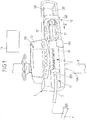
- Fig. 1 shows an embodiment of an infusion device 1 in the shape of a syringe pump having a housing 10 and a receptacle 11 arranged on the housing 10 to receive a syringe 2 therein.
- the syringe 2 comprises a cylindrical tube 20 which, when installing the syringe 2 on the infusion device 1, contains a medical liquid, for example a medication, to be infused to a patient 4.
- the cylindrical tube 20 is connected, via a connector 200, to an infusion line 3 which may extend from the syringe 2 towards a patient 4 for infusing the medical liquid to the patient 4.
- the cylindrical tube 20 of the syringe 2 is placed in the receptacle 11 and is mechanically connected to the housing 10 by means of a fixation device 110.
- the fixation device 110 for example constituted by a releasable clamp element, the cylindrical tube 20 is secured within the receptacle 11 such that the cylindrical tube 20 is held in position on the receptacle 11.
- the syringe 2 comprises a piston 21 which, for delivering medical fluid contained in the cylindrical tube 20, can be pushed into the cylindrical tube 20 in a pushing direction X.
- the infusion device 1 comprises a pumping mechanism 12 having a pusher device 122 movably arranged within a guide device 120 and connected to a suitable drive mechanism via a connecting rod 121.
- the syringe 2 is installed on the infusion device 1 and, for performing an infusion process, the pusher device 122 is electrically moved, controlled by a control device 13 of the infusion device 1, in the pushing direction X to move the piston 21 into the cylindrical tube 20 for delivering the medical fluid contained in the cylindrical tube 20 via the infusion line 3 towards the patient 4.
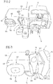
- Fig. 2 to 4 show views of an embodiment of a pump device 1 for example constituted as a syringe pump of the type shown in Fig. 1 .
- the pump device 1 via a fixation device 14, may be arranged on a stand 5 (see Fig. 1 ) such that the pump device 1, in combination for example with other pump devices 1, may be arranged and held at the bedside of a patient.
- the pump device 1 comprises a handset 16 which is connected to the housing 10 of the pump device 1 via a connection cable 160 and comprises a pushbutton 162 which a user may push in order to issue a control command such as for example a command to administer a bolus to a patient.
- the handset 16 may be manually grabbed by a user and serves to input control commands into the pump device 1.
- the handset 16 generally may have one or multiple actuation elements such as pushbuttons 162 and can be removed from the housing 10 in order to allow a user, for example a patient, to enter input commands into the pump device 1.
- connection cable 160 the handset 16 is connected to the control device 13 of the pump device 1 such that signals may be transmitted in between the handset 16 and the control device 13, in particular data signals affecting the operation of the pump device 1.
- connection cable 160 via a connector 161, is connected to a suitable connector 104 of the housing 10 at a bottom side 103 of the housing 10, the bottom side 103 facing downwards in a normal, intended state of operation of the pump device 1.
- the guide device 120 for guiding the pusher device 122 along the movement direction X is formed on a housing section 100 of the housing 10.
- a storage device 15 is arranged and integrally formed with the housing section 100, the storage device 15 serving to store the handset 16 and to receive the connection cable 160.
- the storage device 15 comprises a receptacle 150 defining a cavity 151 therein into which the handset 16 may be inserted.
- the receptacle 150 at its outer circumference comprises an opening 152 in the shape of a slit which extends generally vertical along the receptacle and at a bottom end facing the bottom side 103 of the housing section 100 terminates in an exit opening 153 through which the connection cable 160 may exit from the cavity 151 formed in the receptacle 150.
- the handset 16 may be placed in the cavity 151 of the receptacle 115 in a generally upright position and for this may be inserted into the receptacle 150 through a top end opposite the bottom end of the receptacle 150.
- the receptacle 150 serves to hold and maintain the handset 16 when not in use.
- the handset 16 hence may be placed in a defined location and position on the housing 10 of the pump device 1 such that it is maintained in an organized fashion on the pump device 1.
- the storage device 15 is formed on the back side 102 of the housing section 100. Because the handset 16 is stored in the receptacle 150 of the storage device 15 on the back side 102 of the housing section 100, the handset 16, when stored in the receptacle 150, does not interfere with the regular pumping operation of the pump device 1, in particular the pumping mechanism 12.
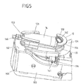
- the storage device 15 furthermore comprises a cable storage 154 formed by a body 155 around which the connection cable 160 may be wound, as shown in Fig. 3 and 4 .
- the body 155 which may have a generally cylindrical shape, is confined at a far end facing away from the housing section 100 by an outer rim 156 radially protruding from the body 155 such that the connection cable 160 wound around the body 155 may not easily slip from the body 155.
- connection cable 160 may be arranged and maintained on the pump device 1 in an organized fashion.
- the handset 16 may be removed from the receptacle 150, and the connection cable 160 may be unwound from the cable storage 154.
- a cable storage 154 and a receptacle 150 are formed as separate units on the housing 10
- a cable storage 154 and a receptacle 150 are integrally formed by a single functional unit.
- a receptacle 150 defines a cavity 151 in which a handset 16 may be placed and may be held by for example providing for a suitable clips connection within the cavity 151.
- the receptacle 150 is arranged at the back side 102 of the housing section 100 and defines an exit opening 153 through which a connection cable 160 connecting the handset 16 to the housing 10 may exit from the receptacle 150.
- the cavity 151 is open towards the back such that the handset 16 may be placed in the receptacle 150 in an insertion direction substantially perpendicular to a back face of the housing section 100 forming the back side 102.
- the receptacle 150 forms a body 155 for the cable storage 154 around which the connection came 160 may be wound, as it is shown in Fig. 5 .
- the body 155 is confined towards the outside by an outer rim 156 transversely protruding from the body 155 such that the connection cable 160 is held and maintained on the body 155 when wound around the body 155.
- the handset may serve to enter control commands of a single or multiple different types. Via the handset for example a command for issuing a bolus may be entered.
- a storage device of the kind described above may be used on pump devices of different types for administering medical fluids to patients, for example constituted as volumetric infusion pumps or syringe infusion pumps.
Landscapes
- Health & Medical Sciences (AREA)
- Vascular Medicine (AREA)
- Engineering & Computer Science (AREA)
- Anesthesiology (AREA)
- Biomedical Technology (AREA)
- Heart & Thoracic Surgery (AREA)
- Hematology (AREA)
- Life Sciences & Earth Sciences (AREA)
- Animal Behavior & Ethology (AREA)
- General Health & Medical Sciences (AREA)
- Public Health (AREA)
- Veterinary Medicine (AREA)
- Infusion, Injection, And Reservoir Apparatuses (AREA)
Description
- The invention relates to a pump device for administering a medical fluid to a patient according to the preamble of claim 1.
- A pump device of this kind comprises a housing, a pumping mechanism for pumping a medical fluid through an infusion line towards a patient, and a handset for entering a control command for controlling an operation of the pumping mechanism, the handset being connected to the housing for example via a connection cable.
- A pump device of this kind may for example be constituted as a volumetric (peristaltic) infusion pump or as a syringe infusion pump. Within a volumetric infusion pump, the pump mechanism, for example comprising a wobbling device as described for example in
WO 2012/049263 A1 , acts onto a pumping module of an infusion line for peristaltically pumping fluid through the infusion line towards a patient. Within a syringe infusion pump, a pumping mechanism, for example comprising a pusher device as for example disclosed inWO2015/062926 A1 , acts onto a piston of a syringe for pushing the piston into a cylindrical barrel of the syringe in order to deliver a fluid from the cylindrical barrel towards a patient. - A pump device of this kind typically is controlled by an electronic control device which controls the pumping mechanism in order to deliver a defined dosage of a medical fluid at a set dose rate. Via the handset, herein, additional control commands may be entered by a user, for example to effect the administration of a bolus. For this, the handset for example may comprise a pushbutton which the user may press in order to enter a control command.
- The handset generally is a piece of equipment which can manually be handled by a user by grabbing it and by actuating an actuation element of the handset such as a pushbutton. The handset is operatively connected to the housing of the pump device and to the control device enclosed in the housing for example via a connection line, the connection line being constituted to electrically transmit signals in between the handset and the control device. Alternatively, it also is conceivable that the handset is connected to the control device wirelessly by a suitable wireless data communication connection.
-
US6355018 is related to a remotely programmable infusion system. The remotely programmable infusion system comprises a memory for storing a programmable protocol and a remote communication port for sending a voice signal to a remote touch-tone transceiver and for receiving a remote programming signal from the remote touch-tone transceiver. -
US2014/194817 relates to medical equipment such as bedside medical pumps for the delivery of medicines to patients, and in particular, to medical equipment that can authenticate, log and adjust its operation according to the authorization of an operator using the medical equipment. -
US2014/121845 relates to the field of medical fluid management machines, in particular a device, a system and a method for monitoring, display of information and operation of a medical fluid management machine. -
WO2013/126318 pertains to contrast media injector systems and, more particularly, to input devices that may be used with such contrast media injector systems.US2007/255116 relates to medical devices and medical device networks, such as infusion systems that deliver fluids into a patient's body. - It is an object of the instant invention to provide a pump device which allows for an improved comfort in particular when using the pump device in a healthcare environment, for example at the bedside of a patient.
- This object is achieved by means of a pump device comprising the features of claim 1.
- Accordingly, the pump device comprises a storage device arranged on the housing and comprising a receptacle defining a cavity therein for receiving the handset.
- By means of the storage device the handset may be placed on the housing of the pump device in an organized fashion. The storage device comprises a receptacle defining a cavity therein, the cavity being formed and shaped such that the handset may be placed within the cavity and, when placed in the cavity, is held on the housing of the pump device in a secure and organized manner.
- By means of the storage device the handset, when not in use, hence may be fixedly held on the housing of the pump device. This increases the comfort for use because the handset is received in a defined place on the housing of the pump device and hence does not disturb normal operation and use of the pump device.
- The receptacle may, in one embodiment, comprise an exit opening for guiding a connection cable out of the receptacle, the connection cable providing for an (electrical) connection of the handset to a control device enclosed in the housing. Via the exit opening the connection cable hence may be guided out of the receptacle towards the housing for connection to the housing.
- The exit opening, in one embodiment, may be arranged on a bottom end of the receptacle, wherein the receptacle is open towards a top end opposite the bottom end such that the handset may be inserted into the cavity defined by the receptacle through the top end. In this case for example an opening in the shape of a slit is arranged on the receptacle through which the connection cable may be inserted into the receptacle when placing the handset in the receptacle.
- In another embodiment, the storage device may comprise a cable storage around which the connection cable can be wound. The cable storage serves to receive the connection cable such that the connection cable may be arranged and maintained on the housing of the pump device in an organized fashion.
- The cable storage, in one embodiment, may be integrally formed with the receptacle. For example, the connection cable may be wound around the receptacle such that the connection cable can be stored on the receptacle.
- In one embodiment, the cable storage comprises a body around which the connection cable can be wound, the body being attached to the housing and extending from the housing such that the connection cable may be placed around the body. In order to store the connection cable in a defined manner on the body, an outer rim may radially protrude from the body such that the body, at a far end pointing away from the housing, is confined by the outer rim. The cable storage hence provides for a confined space in which the connection cable may be stored in an organized fashion.
- In one embodiment, the pumping mechanism is arranged on a front side of the housing. For example, in case of a volumetric (peristaltic) infusion pump a pumping mechanism comprising a wobbling device or the like may be placed on the front side of the housing for acting onto an infusion line placed and received on the front side of the housing. In case of a syringe infusion pump a syringe may be received on the front side of the housing, a pusher device being guided along the front side for acting onto the syringe. Herein, in one embodiment, the storage device is arranged on a back side of the housing opposite the front side such that, when received in the receptacle, the handset is stored and maintained on the housing in a location removed from the pumping mechanism such that the handset and a connection cable extending from the handset may not interfere with a pumping operation.
- In another embodiment, the connection cable comprises a connector by which the connection cable is attached to the housing at a bottom side of the housing. The connector may for example provide for a releasable connection to the housing, the connector being formed for example by a plug connector which can be arranged in a suitable socket arranged on the housing. By connecting the connector to the housing in the region of a bottom side of the housing it can be ensured that the connection cable, at its connection location, is not in the way when conventionally operating the pump device.
- In a specific embodiment the pump device is constituted as a syringe infusion pump comprising a pumping mechanism including a pusher device for acting onto a syringe placed on the pump device. By moving a piston of the syringe a medical fluid may be delivered from the syringe towards a patient. The pusher device herein is guided along a guide device arranged on a housing section of the housing such that the pusher device is translationally movable along the housing for pushing the piston into a cylindrical barrel of the syringe.
- In one embodiment, the storage device for receiving the handset herein may be arranged on said housing section, for example on a back side of said housing section opposite the guide device guiding the pusher device.
- The idea underlying the invention shall subsequently be described in more detail with respect to the embodiments shown in the figures. Herein:
- Fig. 1
- shows a view of an embodiment of an infusion device in the shape of a syringe pump;
- Fig. 2
- shows a back-side view of a pump device according to a first embodiment;
- Fig. 3
- shows another view of the pump device, showing in particular a storage device for receiving a handset of the pump device and a connection cable connected to the handset;
- Fig. 4
- shows another view of the storage device of the pump device; and
- Fig. 5
- shows a storage device of a pump device according to a different embodiment.
-
Fig. 1 shows an embodiment of an infusion device 1 in the shape of a syringe pump having ahousing 10 and areceptacle 11 arranged on thehousing 10 to receive asyringe 2 therein. - The
syringe 2 comprises acylindrical tube 20 which, when installing thesyringe 2 on the infusion device 1, contains a medical liquid, for example a medication, to be infused to a patient 4. Thecylindrical tube 20 is connected, via aconnector 200, to aninfusion line 3 which may extend from thesyringe 2 towards a patient 4 for infusing the medical liquid to the patient 4. - For installing the
syringe 2 on thereceptacle 11 of the infusion device 1, thecylindrical tube 20 of thesyringe 2 is placed in thereceptacle 11 and is mechanically connected to thehousing 10 by means of afixation device 110. By means of thefixation device 110, for example constituted by a releasable clamp element, thecylindrical tube 20 is secured within thereceptacle 11 such that thecylindrical tube 20 is held in position on thereceptacle 11. - The
syringe 2 comprises apiston 21 which, for delivering medical fluid contained in thecylindrical tube 20, can be pushed into thecylindrical tube 20 in a pushing direction X. For this, the infusion device 1 comprises apumping mechanism 12 having apusher device 122 movably arranged within aguide device 120 and connected to a suitable drive mechanism via aconnecting rod 121. - For operating the infusion device 1, the
syringe 2 is installed on the infusion device 1 and, for performing an infusion process, thepusher device 122 is electrically moved, controlled by acontrol device 13 of the infusion device 1, in the pushing direction X to move thepiston 21 into thecylindrical tube 20 for delivering the medical fluid contained in thecylindrical tube 20 via theinfusion line 3 towards the patient 4. -
Fig. 2 to 4 show views of an embodiment of a pump device 1 for example constituted as a syringe pump of the type shown inFig. 1 . The pump device 1, via afixation device 14, may be arranged on a stand 5 (seeFig. 1 ) such that the pump device 1, in combination for example with other pump devices 1, may be arranged and held at the bedside of a patient. - The pump device 1 comprises a
handset 16 which is connected to thehousing 10 of the pump device 1 via aconnection cable 160 and comprises apushbutton 162 which a user may push in order to issue a control command such as for example a command to administer a bolus to a patient. - The
handset 16 may be manually grabbed by a user and serves to input control commands into the pump device 1. Thehandset 16 generally may have one or multiple actuation elements such aspushbuttons 162 and can be removed from thehousing 10 in order to allow a user, for example a patient, to enter input commands into the pump device 1. - Via the
connection cable 160 thehandset 16 is connected to thecontrol device 13 of the pump device 1 such that signals may be transmitted in between thehandset 16 and thecontrol device 13, in particular data signals affecting the operation of the pump device 1. - As visible for example from
Fig. 4 , theconnection cable 160, via aconnector 161, is connected to asuitable connector 104 of thehousing 10 at abottom side 103 of thehousing 10, thebottom side 103 facing downwards in a normal, intended state of operation of the pump device 1. - The
guide device 120 for guiding thepusher device 122 along the movement direction X is formed on ahousing section 100 of thehousing 10. At aback side 102 of the housing section 100 astorage device 15 is arranged and integrally formed with thehousing section 100, thestorage device 15 serving to store thehandset 16 and to receive theconnection cable 160. - The
storage device 15 comprises areceptacle 150 defining acavity 151 therein into which thehandset 16 may be inserted. Thereceptacle 150 at its outer circumference comprises anopening 152 in the shape of a slit which extends generally vertical along the receptacle and at a bottom end facing thebottom side 103 of thehousing section 100 terminates in anexit opening 153 through which theconnection cable 160 may exit from thecavity 151 formed in thereceptacle 150. Thehandset 16 may be placed in thecavity 151 of the receptacle 115 in a generally upright position and for this may be inserted into thereceptacle 150 through a top end opposite the bottom end of thereceptacle 150. - The
receptacle 150 serves to hold and maintain thehandset 16 when not in use. By means of thereceptacle 150 thehandset 16 hence may be placed in a defined location and position on thehousing 10 of the pump device 1 such that it is maintained in an organized fashion on the pump device 1. - Whereas the
pumping mechanism 12 is arranged on afront side 101 of thehousing 10, thestorage device 15 is formed on theback side 102 of thehousing section 100. Because thehandset 16 is stored in thereceptacle 150 of thestorage device 15 on theback side 102 of thehousing section 100, thehandset 16, when stored in thereceptacle 150, does not interfere with the regular pumping operation of the pump device 1, in particular thepumping mechanism 12. - The
storage device 15 furthermore comprises acable storage 154 formed by abody 155 around which theconnection cable 160 may be wound, as shown inFig. 3 and4 . Thebody 155, which may have a generally cylindrical shape, is confined at a far end facing away from thehousing section 100 by anouter rim 156 radially protruding from thebody 155 such that theconnection cable 160 wound around thebody 155 may not easily slip from thebody 155. - By means of the
storage device 15, hence, also theconnection cable 160 may be arranged and maintained on the pump device 1 in an organized fashion. - For using the
handset 16, thehandset 16 may be removed from thereceptacle 150, and theconnection cable 160 may be unwound from thecable storage 154. - Whereas in the embodiment of
Fig. 2 to 4 thecable storage 154 and thereceptacle 150 are formed as separate units on thehousing 10, in the embodiment ofFig. 5 acable storage 154 and areceptacle 150 are integrally formed by a single functional unit. - In particular, in the embodiment of
Fig. 5 areceptacle 150 defines acavity 151 in which ahandset 16 may be placed and may be held by for example providing for a suitable clips connection within thecavity 151. Thereceptacle 150 is arranged at theback side 102 of thehousing section 100 and defines anexit opening 153 through which aconnection cable 160 connecting thehandset 16 to thehousing 10 may exit from thereceptacle 150. Thecavity 151 is open towards the back such that thehandset 16 may be placed in thereceptacle 150 in an insertion direction substantially perpendicular to a back face of thehousing section 100 forming theback side 102. - The
receptacle 150 forms abody 155 for thecable storage 154 around which the connection came 160 may be wound, as it is shown inFig. 5 . Thebody 155 is confined towards the outside by anouter rim 156 transversely protruding from thebody 155 such that theconnection cable 160 is held and maintained on thebody 155 when wound around thebody 155. - The handset may serve to enter control commands of a single or multiple different types. Via the handset for example a command for issuing a bolus may be entered.
- A storage device of the kind described above may be used on pump devices of different types for administering medical fluids to patients, for example constituted as volumetric infusion pumps or syringe infusion pumps.
-
- 1
- Infusion device
- 10
- Housing
- 100
- Housing section
- 101
- Front side
- 102
- Backside
- 103
- Bottom side
- 104
- Connector
- 11
- Receptacle
- 110
- Fixation device
- 12
- Pumping mechanism
- 120
- Guide device
- 121
- Connecting rod
- 122
- Pusher device
- 13
- Control device
- 14
- Fixation device
- 15
- Storage device
- 150
- Receptacle
- 151
- Cavity
- 152
- Opening
- 153
- Exit opening
- 154
- Cable storage
- 155
- Body
- 156
- Outer rim
- 16
- Handset
- 160
- Connection cable
- 161
- Connector
- 162
- Push button
- 2
- syringe
- 20
- Cylinder tube
- 200
- Connector
- 21
- Piston
- 3
- Infusion line
- 4
- Patient
- 5
- Stand
- X
- Movement direction
Claims (6)
- Pump device (1) for administering a medical fluid to a patient (4), comprising:- a housing (10) of the pump device (1),- a pumping mechanism (12) for pumping a medical fluid through an infusion line (3) toward a patient (4), and- a handset (16) for entering a control command for controlling an operation of the pumping mechanism (12),- a storage device (15) arranged on the housing (10) and comprising a receptacle (150) defining a cavity (151) therein for receiving the handset (16),Characterized in that
the handset (16) is connected to the housing (10) via a connection cable (160), wherein the receptacle (150) comprises an exit opening (153) for guiding the connection cable (160) out of the receptacle (150),
the storage device (15) comprises a cable storage (154) around which the connection cable (160) can be wound,
the cable storage (154) comprises a body (155) around which the connection cable (160) can be wound, wherein the body (155) extends from the housing (10) and is confined, at a far end pointing away from the housing (10), by an outer rim (156) protruding from the body (155). - Pump device (1) according to claim 1, characterized in that the exit opening (153) is arranged on a bottom end of the receptacle (150), wherein the receptacle is open towards a top end opposite the bottom end such that the handset (16) is insertable into the cavity (151) defined by the receptacle (150) through the top end.
- Pump device (1) according to claim 1, characterized in that the cable storage (154) is integrally formed with the receptacle (150).
- Pump device (1) according to one of the preceding claims, characterized in that the pumping mechanism (12) is arranged on a front side (101) of the housing (10), whereas the storage device (15) is arranged on a back side (102) of the housing (10) opposite the front side (101).
- Pump device (1) according to one of the preceding claims, characterized in that the connection cable (160) comprises a connector (161) by which the connection cable (160) is attached to the housing (10) at a bottom side of the housing (10).
- Pump device (1) according to one of the preceding claims, characterized in that the pumping mechanism (12) comprises a pusher device (122) for acting onto a syringe (2) for administering a medical fluid from the syringe (2) towards a patient (4), the pusher device (122) being guided along a guide device (120) arranged on a housing section (100) of the housing (10), wherein the storage device (15) is arranged on said housing section (100).
Applications Claiming Priority (2)
| Application Number | Priority Date | Filing Date | Title |
|---|---|---|---|
| EP17305613 | 2017-05-24 | ||
| PCT/EP2018/057224 WO2018215116A1 (en) | 2017-05-24 | 2018-03-22 | Pump device comprising a storage device for receiving a handset |
Publications (2)
| Publication Number | Publication Date |
|---|---|
| EP3630223A1 EP3630223A1 (en) | 2020-04-08 |
| EP3630223B1 true EP3630223B1 (en) | 2021-09-29 |
Family
ID=59034672
Family Applications (1)
| Application Number | Title | Priority Date | Filing Date |
|---|---|---|---|
| EP18713852.4A Active EP3630223B1 (en) | 2017-05-24 | 2018-03-22 | Pump device comprising a storage device for receiving a handset |
Country Status (4)
| Country | Link |
|---|---|
| US (1) | US11565038B2 (en) |
| EP (1) | EP3630223B1 (en) |
| CN (1) | CN110662567B (en) |
| WO (1) | WO2018215116A1 (en) |
Families Citing this family (1)
| Publication number | Priority date | Publication date | Assignee | Title |
|---|---|---|---|---|
| USD909567S1 (en) * | 2017-09-20 | 2021-02-02 | Fresenius Vial Sas | Medical infusion pump |
Family Cites Families (18)
| Publication number | Priority date | Publication date | Assignee | Title |
|---|---|---|---|---|
| US5069668A (en) * | 1990-07-12 | 1991-12-03 | Boydman Scott A | Patient controlled analgesia system |
| US5415287A (en) * | 1992-01-15 | 1995-05-16 | Olympus Optical Co., Ltd. | Endoscope holding and storing apparatus |
| US6355018B1 (en) * | 1995-11-25 | 2002-03-12 | I-Flow Corporation Inc. | Remotely programmable infusion system |
| US5573506A (en) * | 1994-11-25 | 1996-11-12 | Block Medical, Inc. | Remotely programmable infusion system |
| WO2003068295A1 (en) * | 2002-02-18 | 2003-08-21 | Danfoss A/S | System for infusion of medication |
| US20050177111A1 (en) | 2004-02-06 | 2005-08-11 | Shaul Ozeri | Miniature infusion pump |
| US7879008B2 (en) * | 2004-04-08 | 2011-02-01 | Medrad, Inc. | Control device for a fluid delivery system |
| USD529489S1 (en) * | 2005-05-11 | 2006-10-03 | Sbordon Jr William G | Cell phone pocket |
| US7935077B2 (en) * | 2005-09-28 | 2011-05-03 | Medrad, Inc. | Thrombectomy catheter deployment system |
| US20070255126A1 (en) | 2006-04-28 | 2007-11-01 | Moberg Sheldon B | Data communication in networked fluid infusion systems |
| US20100030132A1 (en) * | 2006-09-28 | 2010-02-04 | Jeffrey Niezgoda | Apparatus and method for wound, cavity, and bone treatment |
| US7914483B2 (en) * | 2008-04-02 | 2011-03-29 | Baxter International Inc. | Pain controlled analgesic (“PCA”) apparatus |
| EP2441483A1 (en) | 2010-10-13 | 2012-04-18 | Fresenius Kabi Deutschland GmbH | Pump module, pump base module and pump system |
| US9895484B2 (en) | 2012-02-22 | 2018-02-20 | Liebel-Flarsheim Company Llc | Injector system |
| US9886550B2 (en) | 2012-06-06 | 2018-02-06 | Zyno Medical, Llc | Medical pump with operator-authorization awareness |
| DE102012020945B4 (en) | 2012-10-25 | 2019-10-10 | Fresenius Medical Care Deutschland Gmbh | Apparatus, system and method for monitoring, displaying and operating medical fluid management devices |
| US10589020B2 (en) | 2013-11-04 | 2020-03-17 | Fresenius Vial Sas | Holding device for a syringe pump |
| CN204766828U (en) * | 2015-07-01 | 2015-11-18 | 南通大学附属医院 | Automatic take -up of infusion pump power line |
-
2018
- 2018-03-22 WO PCT/EP2018/057224 patent/WO2018215116A1/en not_active Ceased
- 2018-03-22 EP EP18713852.4A patent/EP3630223B1/en active Active
- 2018-03-22 US US16/615,020 patent/US11565038B2/en active Active
- 2018-03-22 CN CN201880034085.1A patent/CN110662567B/en active Active
Also Published As
| Publication number | Publication date |
|---|---|
| CN110662567B (en) | 2022-06-07 |
| EP3630223A1 (en) | 2020-04-08 |
| US20200078512A1 (en) | 2020-03-12 |
| US11565038B2 (en) | 2023-01-31 |
| CN110662567A (en) | 2020-01-07 |
| WO2018215116A1 (en) | 2018-11-29 |
Similar Documents
| Publication | Publication Date | Title |
|---|---|---|
| US12403252B2 (en) | Infusion device system and apparatus | |
| US11419790B2 (en) | Automatic device for transferring fluid | |
| US10080837B2 (en) | Sterile patch pump | |
| EP2359880A2 (en) | Drug delivery system with wireless monitor | |
| CN110944697A (en) | Casing arrangement for infusion pump | |
| CN101631585A (en) | Infusion medium delivery system, device and method with needle inserter and needle insertion device and method | |
| US10780221B2 (en) | Pulse infusion device system and method | |
| CN112074313A (en) | System and method for syringe handling | |
| EP3436112B1 (en) | Pulse infusion device system and method | |
| US20200078512A1 (en) | Pump device comprising a storage device for receiving a handset | |
| HK40023304B (en) | Pump device comprising a storage device for receiving a handset | |
| HK40023304A (en) | Pump device comprising a storage device for receiving a handset | |
| EP3283144B1 (en) | Pulse infusion device | |
| US20220249768A1 (en) | Cartridge adapter for drug delivery device | |
| HK40084502A (en) | System and method for information management in computerized injectors | |
| WO2019064953A1 (en) | Medical pump, control method for medical pump, and medical pump system |
Legal Events
| Date | Code | Title | Description |
|---|---|---|---|
| STAA | Information on the status of an ep patent application or granted ep patent |
Free format text: STATUS: UNKNOWN |
|
| STAA | Information on the status of an ep patent application or granted ep patent |
Free format text: STATUS: THE INTERNATIONAL PUBLICATION HAS BEEN MADE |
|
| PUAI | Public reference made under article 153(3) epc to a published international application that has entered the european phase |
Free format text: ORIGINAL CODE: 0009012 |
|
| STAA | Information on the status of an ep patent application or granted ep patent |
Free format text: STATUS: REQUEST FOR EXAMINATION WAS MADE |
|
| 17P | Request for examination filed |
Effective date: 20200102 |
|
| AK | Designated contracting states |
Kind code of ref document: A1 Designated state(s): AL AT BE BG CH CY CZ DE DK EE ES FI FR GB GR HR HU IE IS IT LI LT LU LV MC MK MT NL NO PL PT RO RS SE SI SK SM TR |
|
| AX | Request for extension of the european patent |
Extension state: BA ME |
|
| DAV | Request for validation of the european patent (deleted) | ||
| DAX | Request for extension of the european patent (deleted) | ||
| REG | Reference to a national code |
Ref country code: HK Ref legal event code: DE Ref document number: 40023304 Country of ref document: HK |
|
| GRAP | Despatch of communication of intention to grant a patent |
Free format text: ORIGINAL CODE: EPIDOSNIGR1 |
|
| STAA | Information on the status of an ep patent application or granted ep patent |
Free format text: STATUS: GRANT OF PATENT IS INTENDED |
|
| INTG | Intention to grant announced |
Effective date: 20210419 |
|
| RIN1 | Information on inventor provided before grant (corrected) |
Inventor name: DUPREZ, REMI Inventor name: MIREK, YANN Inventor name: PERRIGOUARD, FLORIE Inventor name: CRETINON, THIBAULT Inventor name: RODET, JEAN |
|
| GRAS | Grant fee paid |
Free format text: ORIGINAL CODE: EPIDOSNIGR3 |
|
| GRAA | (expected) grant |
Free format text: ORIGINAL CODE: 0009210 |
|
| STAA | Information on the status of an ep patent application or granted ep patent |
Free format text: STATUS: THE PATENT HAS BEEN GRANTED |
|
| AK | Designated contracting states |
Kind code of ref document: B1 Designated state(s): AL AT BE BG CH CY CZ DE DK EE ES FI FR GB GR HR HU IE IS IT LI LT LU LV MC MK MT NL NO PL PT RO RS SE SI SK SM TR |
|
| REG | Reference to a national code |
Ref country code: GB Ref legal event code: FG4D |
|
| REG | Reference to a national code |
Ref country code: CH Ref legal event code: EP Ref country code: AT Ref legal event code: REF Ref document number: 1433647 Country of ref document: AT Kind code of ref document: T Effective date: 20211015 |
|
| REG | Reference to a national code |
Ref country code: DE Ref legal event code: R096 Ref document number: 602018024254 Country of ref document: DE |
|
| REG | Reference to a national code |
Ref country code: IE Ref legal event code: FG4D |
|
| REG | Reference to a national code |
Ref country code: LT Ref legal event code: MG9D |
|
| PG25 | Lapsed in a contracting state [announced via postgrant information from national office to epo] |
Ref country code: BG Free format text: LAPSE BECAUSE OF FAILURE TO SUBMIT A TRANSLATION OF THE DESCRIPTION OR TO PAY THE FEE WITHIN THE PRESCRIBED TIME-LIMIT Effective date: 20211229 Ref country code: LT Free format text: LAPSE BECAUSE OF FAILURE TO SUBMIT A TRANSLATION OF THE DESCRIPTION OR TO PAY THE FEE WITHIN THE PRESCRIBED TIME-LIMIT Effective date: 20210929 Ref country code: NO Free format text: LAPSE BECAUSE OF FAILURE TO SUBMIT A TRANSLATION OF THE DESCRIPTION OR TO PAY THE FEE WITHIN THE PRESCRIBED TIME-LIMIT Effective date: 20211229 Ref country code: FI Free format text: LAPSE BECAUSE OF FAILURE TO SUBMIT A TRANSLATION OF THE DESCRIPTION OR TO PAY THE FEE WITHIN THE PRESCRIBED TIME-LIMIT Effective date: 20210929 Ref country code: HR Free format text: LAPSE BECAUSE OF FAILURE TO SUBMIT A TRANSLATION OF THE DESCRIPTION OR TO PAY THE FEE WITHIN THE PRESCRIBED TIME-LIMIT Effective date: 20210929 Ref country code: RS Free format text: LAPSE BECAUSE OF FAILURE TO SUBMIT A TRANSLATION OF THE DESCRIPTION OR TO PAY THE FEE WITHIN THE PRESCRIBED TIME-LIMIT Effective date: 20210929 Ref country code: SE Free format text: LAPSE BECAUSE OF FAILURE TO SUBMIT A TRANSLATION OF THE DESCRIPTION OR TO PAY THE FEE WITHIN THE PRESCRIBED TIME-LIMIT Effective date: 20210929 |
|
| REG | Reference to a national code |
Ref country code: NL Ref legal event code: MP Effective date: 20210929 |
|
| REG | Reference to a national code |
Ref country code: AT Ref legal event code: MK05 Ref document number: 1433647 Country of ref document: AT Kind code of ref document: T Effective date: 20210929 |
|
| PG25 | Lapsed in a contracting state [announced via postgrant information from national office to epo] |
Ref country code: LV Free format text: LAPSE BECAUSE OF FAILURE TO SUBMIT A TRANSLATION OF THE DESCRIPTION OR TO PAY THE FEE WITHIN THE PRESCRIBED TIME-LIMIT Effective date: 20210929 Ref country code: GR Free format text: LAPSE BECAUSE OF FAILURE TO SUBMIT A TRANSLATION OF THE DESCRIPTION OR TO PAY THE FEE WITHIN THE PRESCRIBED TIME-LIMIT Effective date: 20211230 |
|
| PG25 | Lapsed in a contracting state [announced via postgrant information from national office to epo] |
Ref country code: AT Free format text: LAPSE BECAUSE OF FAILURE TO SUBMIT A TRANSLATION OF THE DESCRIPTION OR TO PAY THE FEE WITHIN THE PRESCRIBED TIME-LIMIT Effective date: 20210929 |
|
| PG25 | Lapsed in a contracting state [announced via postgrant information from national office to epo] |
Ref country code: IS Free format text: LAPSE BECAUSE OF FAILURE TO SUBMIT A TRANSLATION OF THE DESCRIPTION OR TO PAY THE FEE WITHIN THE PRESCRIBED TIME-LIMIT Effective date: 20220129 Ref country code: SK Free format text: LAPSE BECAUSE OF FAILURE TO SUBMIT A TRANSLATION OF THE DESCRIPTION OR TO PAY THE FEE WITHIN THE PRESCRIBED TIME-LIMIT Effective date: 20210929 Ref country code: RO Free format text: LAPSE BECAUSE OF FAILURE TO SUBMIT A TRANSLATION OF THE DESCRIPTION OR TO PAY THE FEE WITHIN THE PRESCRIBED TIME-LIMIT Effective date: 20210929 Ref country code: PT Free format text: LAPSE BECAUSE OF FAILURE TO SUBMIT A TRANSLATION OF THE DESCRIPTION OR TO PAY THE FEE WITHIN THE PRESCRIBED TIME-LIMIT Effective date: 20220131 Ref country code: PL Free format text: LAPSE BECAUSE OF FAILURE TO SUBMIT A TRANSLATION OF THE DESCRIPTION OR TO PAY THE FEE WITHIN THE PRESCRIBED TIME-LIMIT Effective date: 20210929 Ref country code: NL Free format text: LAPSE BECAUSE OF FAILURE TO SUBMIT A TRANSLATION OF THE DESCRIPTION OR TO PAY THE FEE WITHIN THE PRESCRIBED TIME-LIMIT Effective date: 20210929 Ref country code: ES Free format text: LAPSE BECAUSE OF FAILURE TO SUBMIT A TRANSLATION OF THE DESCRIPTION OR TO PAY THE FEE WITHIN THE PRESCRIBED TIME-LIMIT Effective date: 20210929 Ref country code: EE Free format text: LAPSE BECAUSE OF FAILURE TO SUBMIT A TRANSLATION OF THE DESCRIPTION OR TO PAY THE FEE WITHIN THE PRESCRIBED TIME-LIMIT Effective date: 20210929 Ref country code: CZ Free format text: LAPSE BECAUSE OF FAILURE TO SUBMIT A TRANSLATION OF THE DESCRIPTION OR TO PAY THE FEE WITHIN THE PRESCRIBED TIME-LIMIT Effective date: 20210929 Ref country code: AL Free format text: LAPSE BECAUSE OF FAILURE TO SUBMIT A TRANSLATION OF THE DESCRIPTION OR TO PAY THE FEE WITHIN THE PRESCRIBED TIME-LIMIT Effective date: 20210929 |
|
| REG | Reference to a national code |
Ref country code: DE Ref legal event code: R097 Ref document number: 602018024254 Country of ref document: DE |
|
| PG25 | Lapsed in a contracting state [announced via postgrant information from national office to epo] |
Ref country code: DK Free format text: LAPSE BECAUSE OF FAILURE TO SUBMIT A TRANSLATION OF THE DESCRIPTION OR TO PAY THE FEE WITHIN THE PRESCRIBED TIME-LIMIT Effective date: 20210929 |
|
| PLBE | No opposition filed within time limit |
Free format text: ORIGINAL CODE: 0009261 |
|
| STAA | Information on the status of an ep patent application or granted ep patent |
Free format text: STATUS: NO OPPOSITION FILED WITHIN TIME LIMIT |
|
| 26N | No opposition filed |
Effective date: 20220630 |
|
| PG25 | Lapsed in a contracting state [announced via postgrant information from national office to epo] |
Ref country code: MC Free format text: LAPSE BECAUSE OF FAILURE TO SUBMIT A TRANSLATION OF THE DESCRIPTION OR TO PAY THE FEE WITHIN THE PRESCRIBED TIME-LIMIT Effective date: 20210929 |
|
| REG | Reference to a national code |
Ref country code: CH Ref legal event code: PL |
|
| PG25 | Lapsed in a contracting state [announced via postgrant information from national office to epo] |
Ref country code: SI Free format text: LAPSE BECAUSE OF FAILURE TO SUBMIT A TRANSLATION OF THE DESCRIPTION OR TO PAY THE FEE WITHIN THE PRESCRIBED TIME-LIMIT Effective date: 20210929 |
|
| REG | Reference to a national code |
Ref country code: BE Ref legal event code: MM Effective date: 20220331 |
|
| PG25 | Lapsed in a contracting state [announced via postgrant information from national office to epo] |
Ref country code: LU Free format text: LAPSE BECAUSE OF NON-PAYMENT OF DUE FEES Effective date: 20220322 Ref country code: LI Free format text: LAPSE BECAUSE OF NON-PAYMENT OF DUE FEES Effective date: 20220331 Ref country code: IT Free format text: LAPSE BECAUSE OF FAILURE TO SUBMIT A TRANSLATION OF THE DESCRIPTION OR TO PAY THE FEE WITHIN THE PRESCRIBED TIME-LIMIT Effective date: 20210929 Ref country code: IE Free format text: LAPSE BECAUSE OF NON-PAYMENT OF DUE FEES Effective date: 20220322 Ref country code: CH Free format text: LAPSE BECAUSE OF NON-PAYMENT OF DUE FEES Effective date: 20220331 |
|
| PG25 | Lapsed in a contracting state [announced via postgrant information from national office to epo] |
Ref country code: BE Free format text: LAPSE BECAUSE OF NON-PAYMENT OF DUE FEES Effective date: 20220331 |
|
| P01 | Opt-out of the competence of the unified patent court (upc) registered |
Effective date: 20230528 |
|
| PG25 | Lapsed in a contracting state [announced via postgrant information from national office to epo] |
Ref country code: SM Free format text: LAPSE BECAUSE OF FAILURE TO SUBMIT A TRANSLATION OF THE DESCRIPTION OR TO PAY THE FEE WITHIN THE PRESCRIBED TIME-LIMIT Effective date: 20210929 Ref country code: MK Free format text: LAPSE BECAUSE OF FAILURE TO SUBMIT A TRANSLATION OF THE DESCRIPTION OR TO PAY THE FEE WITHIN THE PRESCRIBED TIME-LIMIT Effective date: 20210929 Ref country code: CY Free format text: LAPSE BECAUSE OF FAILURE TO SUBMIT A TRANSLATION OF THE DESCRIPTION OR TO PAY THE FEE WITHIN THE PRESCRIBED TIME-LIMIT Effective date: 20210929 |
|
| PG25 | Lapsed in a contracting state [announced via postgrant information from national office to epo] |
Ref country code: HU Free format text: LAPSE BECAUSE OF FAILURE TO SUBMIT A TRANSLATION OF THE DESCRIPTION OR TO PAY THE FEE WITHIN THE PRESCRIBED TIME-LIMIT; INVALID AB INITIO Effective date: 20180322 |
|
| PG25 | Lapsed in a contracting state [announced via postgrant information from national office to epo] |
Ref country code: MT Free format text: LAPSE BECAUSE OF FAILURE TO SUBMIT A TRANSLATION OF THE DESCRIPTION OR TO PAY THE FEE WITHIN THE PRESCRIBED TIME-LIMIT Effective date: 20210929 |
|
| PG25 | Lapsed in a contracting state [announced via postgrant information from national office to epo] |
Ref country code: TR Free format text: LAPSE BECAUSE OF FAILURE TO SUBMIT A TRANSLATION OF THE DESCRIPTION OR TO PAY THE FEE WITHIN THE PRESCRIBED TIME-LIMIT Effective date: 20210929 |
|
| PGFP | Annual fee paid to national office [announced via postgrant information from national office to epo] |
Ref country code: GB Payment date: 20260327 Year of fee payment: 9 |
|
| PGFP | Annual fee paid to national office [announced via postgrant information from national office to epo] |
Ref country code: DE Payment date: 20260327 Year of fee payment: 9 |
|
| PGFP | Annual fee paid to national office [announced via postgrant information from national office to epo] |
Ref country code: FR Payment date: 20260325 Year of fee payment: 9 |