EP3629457A1 - Power module - Google Patents
Power module Download PDFInfo
- Publication number
- EP3629457A1 EP3629457A1 EP19197684.4A EP19197684A EP3629457A1 EP 3629457 A1 EP3629457 A1 EP 3629457A1 EP 19197684 A EP19197684 A EP 19197684A EP 3629457 A1 EP3629457 A1 EP 3629457A1
- Authority
- EP
- European Patent Office
- Prior art keywords
- power
- jumping
- terminal
- capacitor
- terminals
- Prior art date
- Legal status (The legal status is an assumption and is not a legal conclusion. Google has not performed a legal analysis and makes no representation as to the accuracy of the status listed.)
- Granted
Links
Images



Classifications
-
- H—ELECTRICITY
- H02—GENERATION; CONVERSION OR DISTRIBUTION OF ELECTRIC POWER
- H02M—APPARATUS FOR CONVERSION BETWEEN AC AND AC, BETWEEN AC AND DC, OR BETWEEN DC AND DC, AND FOR USE WITH MAINS OR SIMILAR POWER SUPPLY SYSTEMS; CONVERSION OF DC OR AC INPUT POWER INTO SURGE OUTPUT POWER; CONTROL OR REGULATION THEREOF
- H02M1/00—Details of apparatus for conversion
- H02M1/12—Arrangements for reducing harmonics from AC input or output
- H02M1/126—Arrangements for reducing harmonics from AC input or output using passive filters
-
- H—ELECTRICITY
- H02—GENERATION; CONVERSION OR DISTRIBUTION OF ELECTRIC POWER
- H02M—APPARATUS FOR CONVERSION BETWEEN AC AND AC, BETWEEN AC AND DC, OR BETWEEN DC AND DC, AND FOR USE WITH MAINS OR SIMILAR POWER SUPPLY SYSTEMS; CONVERSION OF DC OR AC INPUT POWER INTO SURGE OUTPUT POWER; CONTROL OR REGULATION THEREOF
- H02M1/00—Details of apparatus for conversion
- H02M1/44—Circuits or arrangements for compensating for electromagnetic interference in converters or inverters
-
- H—ELECTRICITY
- H02—GENERATION; CONVERSION OR DISTRIBUTION OF ELECTRIC POWER
- H02M—APPARATUS FOR CONVERSION BETWEEN AC AND AC, BETWEEN AC AND DC, OR BETWEEN DC AND DC, AND FOR USE WITH MAINS OR SIMILAR POWER SUPPLY SYSTEMS; CONVERSION OF DC OR AC INPUT POWER INTO SURGE OUTPUT POWER; CONTROL OR REGULATION THEREOF
- H02M3/00—Conversion of DC power input into DC power output
- H02M3/02—Conversion of DC power input into DC power output without intermediate conversion into AC
- H02M3/04—Conversion of DC power input into DC power output without intermediate conversion into AC by static converters
- H02M3/10—Conversion of DC power input into DC power output without intermediate conversion into AC by static converters using discharge tubes with control electrode or semiconductor devices with control electrode
- H02M3/145—Conversion of DC power input into DC power output without intermediate conversion into AC by static converters using discharge tubes with control electrode or semiconductor devices with control electrode using devices of a triode or transistor type requiring continuous application of a control signal
- H02M3/155—Conversion of DC power input into DC power output without intermediate conversion into AC by static converters using discharge tubes with control electrode or semiconductor devices with control electrode using devices of a triode or transistor type requiring continuous application of a control signal using semiconductor devices only
- H02M3/156—Conversion of DC power input into DC power output without intermediate conversion into AC by static converters using discharge tubes with control electrode or semiconductor devices with control electrode using devices of a triode or transistor type requiring continuous application of a control signal using semiconductor devices only with automatic control of output voltage or current, e.g. switching regulators
- H02M3/158—Conversion of DC power input into DC power output without intermediate conversion into AC by static converters using discharge tubes with control electrode or semiconductor devices with control electrode using devices of a triode or transistor type requiring continuous application of a control signal using semiconductor devices only with automatic control of output voltage or current, e.g. switching regulators including plural semiconductor devices as final control devices for a single load
-
- H—ELECTRICITY
- H02—GENERATION; CONVERSION OR DISTRIBUTION OF ELECTRIC POWER
- H02M—APPARATUS FOR CONVERSION BETWEEN AC AND AC, BETWEEN AC AND DC, OR BETWEEN DC AND DC, AND FOR USE WITH MAINS OR SIMILAR POWER SUPPLY SYSTEMS; CONVERSION OF DC OR AC INPUT POWER INTO SURGE OUTPUT POWER; CONTROL OR REGULATION THEREOF
- H02M7/00—Conversion of AC power input into DC power output; Conversion of DC power input into AC power output
- H02M7/42—Conversion of DC power input into AC power output without possibility of reversal
- H02M7/44—Conversion of DC power input into AC power output without possibility of reversal by static converters
- H02M7/48—Conversion of DC power input into AC power output without possibility of reversal by static converters using discharge tubes with control electrode or semiconductor devices with control electrode
- H02M7/53—Conversion of DC power input into AC power output without possibility of reversal by static converters using discharge tubes with control electrode or semiconductor devices with control electrode using devices of a triode or transistor type requiring continuous application of a control signal
- H02M7/537—Conversion of DC power input into AC power output without possibility of reversal by static converters using discharge tubes with control electrode or semiconductor devices with control electrode using devices of a triode or transistor type requiring continuous application of a control signal using semiconductor devices only, e.g. single switched pulse inverters
- H02M7/5387—Conversion of DC power input into AC power output without possibility of reversal by static converters using discharge tubes with control electrode or semiconductor devices with control electrode using devices of a triode or transistor type requiring continuous application of a control signal using semiconductor devices only, e.g. single switched pulse inverters in a bridge configuration
-
- H—ELECTRICITY
- H03—ELECTRONIC CIRCUITRY
- H03H—IMPEDANCE NETWORKS, e.g. RESONANT CIRCUITS; RESONATORS
- H03H7/00—Multiple-port networks comprising only passive electrical elements as network components
- H03H7/42—Networks for transforming balanced signals into unbalanced signals and vice versa, e.g. baluns
- H03H7/425—Balance-balance networks
- H03H7/427—Common-mode filters
-
- Y—GENERAL TAGGING OF NEW TECHNOLOGICAL DEVELOPMENTS; GENERAL TAGGING OF CROSS-SECTIONAL TECHNOLOGIES SPANNING OVER SEVERAL SECTIONS OF THE IPC; TECHNICAL SUBJECTS COVERED BY FORMER USPC CROSS-REFERENCE ART COLLECTIONS [XRACs] AND DIGESTS
- Y02—TECHNOLOGIES OR APPLICATIONS FOR MITIGATION OR ADAPTATION AGAINST CLIMATE CHANGE
- Y02B—CLIMATE CHANGE MITIGATION TECHNOLOGIES RELATED TO BUILDINGS, e.g. HOUSING, HOUSE APPLIANCES OR RELATED END-USER APPLICATIONS
- Y02B70/00—Technologies for an efficient end-user side electric power management and consumption
- Y02B70/10—Technologies improving the efficiency by using switched-mode power supplies [SMPS], i.e. efficient power electronics conversion e.g. power factor correction or reduction of losses in power supplies or efficient standby modes
Definitions
- the present invention relates to power modules, and particularly to a power module with low EMI (Electro-Magnetic Interference) noise.
- EMI Electro-Magnetic Interference
- SIC power semiconductor devices have been increasingly used in high-power power electronic converters due to their excellent switching characteristics.
- the SIC power semiconductor devices can be a discrete component packaging, such as TO220, TO247, etc, and thereby the package is standardized, the cost is relatively low, and the reliability is relatively high.
- parasitic parameters such as stray inductance
- EMI problems can exist in the case of large parasitic parameters application. Therefore, in some high power application, such as power of above 10KW, SIC power modules can be applied.
- the power module can significantly reduce internal parasitic parameters, and it is more suitable for usage of SIC die connected in parallel.
- the driver of the power module utilizes the Kevin connection, and the power source and the driver source are completely isolated, thus the problem of common source does not exist and the switching loss can be reduced a lot.
- the SIC device is a high-speed wide band-gap switch device, the voltage rise rate dv/dt and the current rise rate di/dt of the switching transistor are relatively high, thus the EMI noise is relatively large.
- the EMI noise is relatively large.
- the half-bridge power module have three power terminals, IN+, IN-, and AC, where the AC terminal is an EMI noise source.
- the half-bridge power module includes a bridge arm having two semiconductors, by integrating the two semiconductors together, the length of the wires between the two semiconductors can be reduced, and the heat dissipation problem of the switches can be solved. Meanwhile, placing a high frequency capacitor outside and connected with the power terminals can reduce the switching peak and EMI noise.
- FIG. 2 shows a conventional buck circuit including a half-bridge power module.
- the power module M' includes a bridge arm having two power devices Q 1 and Q 2 connected in series, and has three power terminals of IN+, IN- and AC.
- the IN- and AC terminal are electrically connected to an inductor L and an output capacitor C 2
- the IN+ and IN- terminal are electrically connected to an input source Vin and an input capacitor C 1 .
- the stray inductance of the first loop C L1 which includes power devices Q 1 and Q 2 , and capacitor C 1 , will be relatively large and thus affect EMC (Electro-Magnetic Compatibility) characteristics.
- EMC Electro-Magnetic Compatibility
- the high-frequency ceramic capacitor C 1 can be integrated inside the half-bridge power module and disposed at the position closest to the power terminals IN+ and IN- of the power devices Q 1 and Q 2 , as shown in Figure 3 , which can greatly absorb excessive high voltage overshooting and therefore improves system reliability.
- the second loop C L2 indicated in Figure 2 has a parasitic parallel capacitance C L of the output inductor L and a loop parasitic inductance (not shown), therefore the noise of high frequency on the AC terminal passes from the parasitic C L to the IN- terminal, which also causes high frequency EMC problems.
- FIG. 4 shows an EMI analysis circuit of a half-bridge power module M' applied in a typical buck circuit application, which includes a buck circuit, a primary EMI filter, an EMI LSIN, and an output impedance.
- C para1 is the parasitic capacitor of the power inductor L.
- L para1 is the parasitic inductance between a terminal A2 of capacitor C X1 and the fixed point A3 of power module M', and L para2 is the parasitic inductance between the point A1 and the capacitor C X1 .
- V A 1 A 2 V noise * ZL para 2 / ZL para 1 + ZC para 1 + ZL para 2
- V A 2 A 3 V noise * ZL para 1 / ZL para 1 + ZC para 1 + ZL para 2
- V noise is the noise voltage between the AC terminal and the IN- terminal.
- ZL para1 , ZL para2 , and ZC para1 are the impedances of parasitic inductance L para1 , parasitic inductance L para2 , and parasitic capacitance C para1 , respectively.
- the voltage V A1A2 of A1A2 is converted into differential mode noise, and the voltage V A2A3 of A2A3 is converted into common mode noise.
- the present invention intends to provide a power module, which has low EMI noise and can greatly reduce engineers' time for solving EMI.
- the present invention provides a power module, wherein the power module comprising:
- the present invention adds at least one non-jumping power terminal based on the existing power module technology, and the non-jumping power terminal and a jumping power terminal are respectively electrically connected to two terminals of a power inductor; and the present invention also adds a high frequency capacitor between the non-jumping power terminal and at least one of other non-jumping power terminals, therefore further reduces EMI noise and significantly saves engineers time for solving EMI.
- the power module of the present invention has at least three non-jumping power terminals and at least one jumping power terminal.
- the at least three non-jumping power terminals are at non-jumping potentials
- multiple power devices and at least one first capacitor are electrically connected between a first non-jumping power terminal and a second non-jumping power terminal.
- At least one jumping power terminal is at a jumping potential.
- a first jumping power terminal is electrically connected to one terminal of a power inductor and a third non-jumping power terminal is electrically connected to the other terminal of the power inductor.
- at least one second capacitor are electrically connected between the third non-jumping power terminal and at least one of other non-jumping power terminals.
- the "non-jumping potential” generally refers to a potential, which is at fixed potential or has tiny high-low level jumping with respect to a reference potential point.
- the tiny high-low level jumping can be, for example, a voltage rising rate dv/dt less than 2V/us.
- the "jumping potential” generally refers to having a large high-low level jumping with respect to the reference potential point.
- the large high-low level jumping can be, for example, the voltage rising rate dv/dt greater than 10 V/us.
- the threshold values of the above voltage rising rate dv/dt may also be variable fluctuate within a certain range, such as, but not limited to, ten percent, or five percent of 2V/us or 10V/us etc.
- the power module M includes four power terminals, that is, terminals IN+, IN-, AC and OUT. Wherein terminals IN+, IN- and OUT are non-jumping power terminals at a non-jumping potential, and the terminal AC is jumping terminal at a jumping potential.
- two power devices Q 1 and Q 2 and a capacitor C 1 are electrically connected between terminals IN+ and IN-.
- the above two power devices Q 1 and Q 2 are connected in series and configured as a bridge arm.
- the capacitor C 1 is connected in parallel with this bridge arm, and terminals AC and OUT are used to respectively electrically connect to both two terminals of a power inductor, and a capacitor C 2 is also electrically connected between terminals OUT and IN-.
- terminals IN+, IN-, AC, and OUT are respectively power terminals with current values greater than 1A.
- terminals IN+, OUT, and IN- are terminals at a fixed potential, for example, the terminal IN- serves as the reference point at a reference potential (such as a zero potential).
- Terminals IN+ and OUT are also at fixed potentials with respect to the terminal IN-, which is shown in Figure 6c .
- the terminal AC has a relative large high-low level jumping with respect to the terminal IN- (reference point), that is, there is a relative large voltage rising rate dv/dt between AC and IN- (for example, dv/dt > 10V/us), which is the noise source of EMI.
- terminals IN+, OUT, and IN- may also be sinusoidal ripples superimposed with a frequency ⁇ 10kHz, and the voltage rising rate dv/dt is relatively small, such as less than 2V/us, as shown in Figure 6b .
- the terminal OUT also may also be provided with an AC voltage with a frequency ⁇ 10kHz, which is also shown in Figure 6a .
- the capacitors C 1 , C 2 may be high frequency capacitors. More preferably, the capacitor C 2 can be a SMC or a capacitor die, and the value of the capacitor can be, for example, greater than 1nF.
- FIG 7 shows an EMI analysis circuit of a power module applied in a typical buck circuit according to the present invention.
- a power terminal OUT and a capacitor C 2 are added to the power module M of the present invention, and the capacitor C 2 is a high frequency capacitor with a parasitic inductance ⁇ 1nH.
- the value of the capacitor C 2 is much larger than the parasitic capacitance C para1 of the power inductor L.
- the parasitic inductances L para1 and L para2 are relatively small, so in high frequency, the impedance at both terminals of A1A2 is approximately equal to the impedance ZC 2 of the capacitor C 2 and the voltage V A1A3 across A1A3 is approximated equals to V noise *ZC 2 /(ZC 2 + ZC para1 ). Since ZC 2 is much smaller than ZC para1 , the noise amplitude at across A1A3 is significantly reduced.
- Figure 8 is a waveform schematic diagram obtained by performing RFI testing on the power module under a first-stage EMI filter according to the present invention.
- the waveform of the RFI is obtained from the test under the topology of the high-speed switching device GaN, as shown in Figure 8 . Seen from the waveform, the above power supply under first-level EMI filtering could satisfy the Class B standard.
- the power module of the present invention is not limited to the above topology, and it can be widely applied to topologies such as boost, buck, Herric, and T-type three level, etc. At least one jumping node and at least three non-jumping nodes should be included in each topology. Moreover, the power terminal of the power module of the present invention in each topology should include both terminals of the power inductor and a non-jumping power terminal.
- FIG. 9a to 9h it shows topology circuits of the power modules according to other preferred embodiments.
- the difference between the power module thereof and that shown in Figure 5 is that: in the power module shown in Figure 9a , the capacitor C 2 is electrically connected between terminals OUT and IN+; In the power module shown in Figure 9b , the capacitor C 2 is electrically connected between terminals OUT and IN+, and the capacitor C 3 is electrically connected between terminals OUT and IN-.
- the difference between the power module thereof and that shown in Figure 5 is that: the power module shown in Figure 9c to Figure 9e includes two half-bridge arms between terminals IN+ and IN-, which respectively includes power devices Q 1 and Q 2 connected in series, and Q 3 and Q 4 connected in series. And terminals AC1 and AC2 terminal at a jumping potential are the center points of the two half-bridge arms respectively.
- the capacitor C 2 is electrically connected between terminals OUT and IN-; in the power module shown in Figure 9d , the capacitor C 2 is electrically connected between terminals OUT and IN+.
- the capacitor C 2 is electrically connected between terminals OUT and IN+, and the capacitor C 3 is electrically connected between terminals OUT and IN-.
- the difference between the power module thereof and that shown in Figure 5 is that: the power module shown in Figure 9f to Figure 9h includes a full-bridge arm between terminals IN+ and IN-, which includes power devices Q 1 , Q 2 , Q 3 and Q 4 connected in series.
- the power module further includes a first bridge arm having diodes D 1 and D 2 connected in series, which is connected in parallel with both terminals of the power devices Q 2 and Q 3 .
- a second bridge arm having capacitors C 1 and C 2 connected in series is included between terminals IN+ and IN-, and the terminal COM at a non-jumping potential is a center point of the first bridge arm and the second bridge arm.
- the capacitor C 3 is electrically connected between the terminal OUT and the second bridge arm.
- the capacitor C 3 is electrically connected between terminals OUT and IN+ terminals.
- the capacitor C 3 is electrically connected between terminals OUT and IN-.
- the present invention can also add a power terminal OUT2 as an auxiliary terminal on the terminal of the capacitor C 2 , and the terminal OUT2 is electrically connected to the OUT1 terminal.
- the terminals AC and OUT1 are electrically connected at both terminals of the power inductor (such as the power inductor L in Figure 7 ), and the terminal OUT2 is a non-jumping power terminal and is connected to one terminal of the external capacitor (such as capacitor C X1 in Figure 7 ). This minimizes the equivalent inductance of C 2 , and compared with the power module shown in Figure 5 , EMI noise is less.
Landscapes
- Engineering & Computer Science (AREA)
- Power Engineering (AREA)
- Physics & Mathematics (AREA)
- Electromagnetism (AREA)
- Inverter Devices (AREA)
- Dc-Dc Converters (AREA)
Abstract
Description
- The present invention relates to power modules, and particularly to a power module with low EMI (Electro-Magnetic Interference) noise.
- In recent years, SIC power semiconductor devices have been increasingly used in high-power power electronic converters due to their excellent switching characteristics. At present, the SIC power semiconductor devices can be a discrete component packaging, such as TO220, TO247, etc, and thereby the package is standardized, the cost is relatively low, and the reliability is relatively high. However, it also brings some problems, such as parasitic parameters (such as stray inductance) are relatively high and large EMI problems can exist in the case of large parasitic parameters application. Therefore, in some high power application, such as power of above 10KW, SIC power modules can be applied. The power module can significantly reduce internal parasitic parameters, and it is more suitable for usage of SIC die connected in parallel. Meanwhile, the driver of the power module utilizes the Kevin connection, and the power source and the driver source are completely isolated, thus the problem of common source does not exist and the switching loss can be reduced a lot. However, since the SIC device is a high-speed wide band-gap switch device, the voltage rise rate dv/dt and the current rise rate di/dt of the switching transistor are relatively high, thus the EMI noise is relatively large. There is the same problem as in all high-speed switching devices such as GaN.
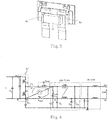
- As shown
Figure 1 , in which a typical half-bridge power module is shown. The half-bridge power module have three power terminals, IN+, IN-, and AC, where the AC terminal is an EMI noise source. Moreover, the half-bridge power module includes a bridge arm having two semiconductors, by integrating the two semiconductors together, the length of the wires between the two semiconductors can be reduced, and the heat dissipation problem of the switches can be solved. Meanwhile, placing a high frequency capacitor outside and connected with the power terminals can reduce the switching peak and EMI noise. - As shown
Figure 2 , in which shows a conventional buck circuit including a half-bridge power module. The power module M' includes a bridge arm having two power devices Q1 and Q2 connected in series, and has three power terminals of IN+, IN- and AC. The IN- and AC terminal are electrically connected to an inductor L and an output capacitor C2, and the IN+ and IN- terminal are electrically connected to an input source Vin and an input capacitor C1. However, due to the physical size of the power module M' itself, the stray inductance of the first loop CL1, which includes power devices Q1 and Q2, and capacitor C1, will be relatively large and thus affect EMC (Electro-Magnetic Compatibility) characteristics. In prior art, the high-frequency ceramic capacitor C1 can be integrated inside the half-bridge power module and disposed at the position closest to the power terminals IN+ and IN- of the power devices Q1 and Q2 , as shown inFigure 3 , which can greatly absorb excessive high voltage overshooting and therefore improves system reliability. However, the second loop CL2 indicated inFigure 2 has a parasitic parallel capacitance CL of the output inductor L and a loop parasitic inductance (not shown), therefore the noise of high frequency on the AC terminal passes from the parasitic CL to the IN- terminal, which also causes high frequency EMC problems. - Specifically, as shown
Figure 4 , in which shows an EMI analysis circuit of a half-bridge power module M' applied in a typical buck circuit application, which includes a buck circuit, a primary EMI filter, an EMI LSIN, and an output impedance. Wherein Cpara1 is the parasitic capacitor of the power inductor L. Lpara1 is the parasitic inductance between a terminal A2 of capacitor CX1 and the fixed point A3 of power module M', and Lpara2 is the parasitic inductance between the point A1 and the capacitor CX1. - Moreover, at high frequency, the impedance of the power inductor L is very large, while the impedance of the capacitor CX1 is very small. The voltage across A1A2 and the voltage across A2A3 are approximately calculated as below:


- Wherein, Vnoise is the noise voltage between the AC terminal and the IN- terminal. ZLpara1, ZLpara2, and ZCpara1 are the impedances of parasitic inductance Lpara1, parasitic inductance Lpara2, and parasitic capacitance Cpara1, respectively. The voltage VA1A2 of A1A2 is converted into differential mode noise, and the voltage VA2A3 of A2A3 is converted into common mode noise. Given above, the higher the frequency is, the greater the impedance of the inductance (for example, the parasitic inductance Lpara1 and the parasitic inductance Lpara2) and the greater the noise are.
- Therefore, there is an urgent need for a power module with low EMI noise.
- In view of this, the present invention intends to provide a power module, which has low EMI noise and can greatly reduce engineers' time for solving EMI.
- In order to realize the above purpose, the present invention provides a power module, wherein the power module comprising:
- at least three non-jumping power terminals at a non-jumping potential, wherein multiple power devices and at least one first capacitor are electrically connected between a first non-jumping power terminal and a second non-jumping power terminal of the at least three non-jumping power terminals; and
- at least one jumping power terminal at a jumping potential, wherein a first jumping power terminal of the at least one jumping power terminal is electrically connected to one terminal of a power inductor and a third non-jumping power terminal of the at least three non-jumping power terminals is electrically connected to the other terminal of the power inductor;
- wherein at least one second capacitor is electrically connected between the third non-jumping power terminal and at least one of other non-jumping power terminals of the at least three non-jumping power terminals.
- The present invention adds at least one non-jumping power terminal based on the existing power module technology, and the non-jumping power terminal and a jumping power terminal are respectively electrically connected to two terminals of a power inductor; and the present invention also adds a high frequency capacitor between the non-jumping power terminal and at least one of other non-jumping power terminals, therefore further reduces EMI noise and significantly saves engineers time for solving EMI.
- The above description will be further described in detail below, as well as the further interpretation of the technical solution of the present invention will be provided
- To make the above and other objects, features, advantages and examples of the invention more apparent and straightforward, a brief description of the drawings is provided as follows:
-
Figure1 is a schematic diagram of the structure of a conventional half-bridge power module; -
Figure 2 is a circuit schematic diagram of a conventional power module applied in the typical buck circuit; -
Figure 3 is a schematic diagram of the structure of a power module of the existing integrated high frequency capacitors; -
Figure 4 is a schematic diagram of an EMI analysis circuit of a conventional power module applied in a typical buck circuit; -
Figure 5 is a schematic diagram of the structure of a power module according to a preferred embodiment of the present invention; -
Figures 6a-6c are voltage schematic diagrams of the non-jumping pin ofFigure 5 with respect to a reference point; -
Figure 7 is a schematic diagram of an EMI analysis circuit of a power module applied in a typical buck circuit according to the present invention. -
Figure 8 is a waveform schematic diagram obtained by performing RFI testing of the power module under a first-stage EMI filter according to the present invention. -
Figures 9a-9h are schematic diagrams of a topology circuit of a power module according to another preferred embodiment of the present invention; -
Figure 10 is a schematic diagram of an optimized circuit of a power module according to another preferred embodiment of the present invention. - In order to make the description of the invention more elaborate and complete, reference may be made to the accompanying drawings and the various examples described below, and the same numbers in the drawings represent the same or similar components. On the other hand, well-known components and steps are not described in the examples to avoid unnecessarily limiting the invention. In addition, some of the conventional structures and elements already known are shown in the drawings in a simplified schematic manner to simplify the drawings.
- The power module of the present invention has at least three non-jumping power terminals and at least one jumping power terminal. Wherein, the at least three non-jumping power terminals are at non-jumping potentials, and multiple power devices and at least one first capacitor are electrically connected between a first non-jumping power terminal and a second non-jumping power terminal. At least one jumping power terminal is at a jumping potential. A first jumping power terminal is electrically connected to one terminal of a power inductor and a third non-jumping power terminal is electrically connected to the other terminal of the power inductor. And at least one second capacitor are electrically connected between the third non-jumping power terminal and at least one of other non-jumping power terminals.
- In the present invention, the "non-jumping potential" generally refers to a potential, which is at fixed potential or has tiny high-low level jumping with respect to a reference potential point. The tiny high-low level jumping can be, for example, a voltage rising rate dv/dt less than 2V/us. The "jumping potential" generally refers to having a large high-low level jumping with respect to the reference potential point. The large high-low level jumping can be, for example, the voltage rising rate dv/dt greater than 10 V/us. In one embodiment, the threshold values of the above voltage rising rate dv/dt, such as 2V/us or 10V/us, may also be variable fluctuate within a certain range, such as, but not limited to, ten percent, or five percent of 2V/us or 10V/us etc.
- As shown
Figure 5 , in which shows a structure of a power module according to a preferred embodiment of the present invention. The power module M includes four power terminals, that is, terminals IN+, IN-, AC and OUT. Wherein terminals IN+, IN- and OUT are non-jumping power terminals at a non-jumping potential, and the terminal AC is jumping terminal at a jumping potential. In this embodiment, two power devices Q1 and Q2 and a capacitor C1 are electrically connected between terminals IN+ and IN-. The above two power devices Q1 and Q2 are connected in series and configured as a bridge arm. The capacitor C1 is connected in parallel with this bridge arm, and terminals AC and OUT are used to respectively electrically connect to both two terminals of a power inductor, and a capacitor C2 is also electrically connected between terminals OUT and IN-. - In this embodiment, terminals IN+, IN-, AC, and OUT are respectively power terminals with current values greater than 1A. Wherein terminals IN+, OUT, and IN- are terminals at a fixed potential, for example, the terminal IN- serves as the reference point at a reference potential (such as a zero potential). Terminals IN+ and OUT are also at fixed potentials with respect to the terminal IN-, which is shown in
Figure 6c . The terminal AC has a relative large high-low level jumping with respect to the terminal IN- (reference point), that is, there is a relative large voltage rising rate dv/dt between AC and IN- (for example, dv/dt > 10V/us), which is the noise source of EMI. In other embodiments, terminals IN+, OUT, and IN- may also be sinusoidal ripples superimposed with a frequency <10kHz, and the voltage rising rate dv/dt is relatively small, such as less than 2V/us, as shown inFigure 6b . In other embodiments, with respect to the terminal IN-, the terminal OUT also may also be provided with an AC voltage with a frequency <10kHz, which is also shown inFigure 6a . - Preferably, in an embodiment of the invention, the capacitors C1, C2 may be high frequency capacitors. More preferably, the capacitor C2 can be a SMC or a capacitor die, and the value of the capacitor can be, for example, greater than 1nF.
- As shown
Figure 7 , in which shows an EMI analysis circuit of a power module applied in a typical buck circuit according to the present invention. Wherein, with respect to the conventional power module M' shown inFigure 4 , a power terminal OUT and a capacitor C2 are added to the power module M of the present invention, and the capacitor C2 is a high frequency capacitor with a parasitic inductance <1nH. The value of the capacitor C2 is much larger than the parasitic capacitance Cpara1 of the power inductor L. The parasitic inductances Lpara1 and Lpara2 are relatively small, so in high frequency, the impedance at both terminals of A1A2 is approximately equal to the impedance ZC2 of the capacitor C2 and the voltage VA1A3 across A1A3 is approximated equals to Vnoise*ZC2/(ZC2+ ZCpara1). Since ZC2 is much smaller than ZCpara1, the noise amplitude at across A1A3 is significantly reduced. -
Figure 8 is a waveform schematic diagram obtained by performing RFI testing on the power module under a first-stage EMI filter according to the present invention. Using the connection mode of the power module of the present invention, the waveform of the RFI is obtained from the test under the topology of the high-speed switching device GaN, as shown inFigure 8 . Seen from the waveform, the above power supply under first-level EMI filtering could satisfy the Class B standard. - It can be understood that the power module of the present invention is not limited to the above topology, and it can be widely applied to topologies such as boost, buck, Herric, and T-type three level, etc. At least one jumping node and at least three non-jumping nodes should be included in each topology. Moreover, the power terminal of the power module of the present invention in each topology should include both terminals of the power inductor and a non-jumping power terminal.
- As shown
Figure 9a to 9h , it shows topology circuits of the power modules according to other preferred embodiments. - As shown
Figure 9a to 9b , the difference between the power module thereof and that shown inFigure 5 is that: in the power module shown inFigure 9a , the capacitor C2 is electrically connected between terminals OUT and IN+; In the power module shown inFigure 9b , the capacitor C2 is electrically connected between terminals OUT and IN+, and the capacitor C3 is electrically connected between terminals OUT and IN-. - As shown in
Figure 9c to Figure 9e , the difference between the power module thereof and that shown inFigure 5 is that: the power module shown inFigure 9c to Figure 9e includes two half-bridge arms between terminals IN+ and IN-, which respectively includes power devices Q1 and Q2 connected in series, and Q3 and Q4 connected in series. And terminals AC1 and AC2 terminal at a jumping potential are the center points of the two half-bridge arms respectively. Moreover, in the power module shown inFigure 9c , the capacitor C2 is electrically connected between terminals OUT and IN-; in the power module shown inFigure 9d , the capacitor C2 is electrically connected between terminals OUT and IN+. In the power module shown inFigure 9e , the capacitor C2 is electrically connected between terminals OUT and IN+, and the capacitor C3 is electrically connected between terminals OUT and IN-. - As shown in
Figure 9f to Figure 9h , the difference between the power module thereof and that shown inFigure 5 is that: the power module shown inFigure 9f to Figure 9h includes a full-bridge arm between terminals IN+ and IN-, which includes power devices Q1, Q2, Q3 and Q4 connected in series. The power module further includes a first bridge arm having diodes D1 and D2 connected in series, which is connected in parallel with both terminals of the power devices Q2 and Q3. A second bridge arm having capacitors C1 and C2 connected in series is included between terminals IN+ and IN-, and the terminal COM at a non-jumping potential is a center point of the first bridge arm and the second bridge arm. Also, in the power module shown inFigure 9f , the capacitor C3 is electrically connected between the terminal OUT and the second bridge arm. In the power module indicated inFigure 9g , the capacitor C3 is electrically connected between terminals OUT and IN+ terminals. In the power module indicated inFigure 9h , the capacitor C3 is electrically connected between terminals OUT and IN-. - As shown in
Figure 10 , in order to better optimize the effect of EMI, the present invention can also add a power terminal OUT2 as an auxiliary terminal on the terminal of the capacitor C2, and the terminal OUT2 is electrically connected to the OUT1 terminal. The terminals AC and OUT1 are electrically connected at both terminals of the power inductor (such as the power inductor L inFigure 7 ), and the terminal OUT2 is a non-jumping power terminal and is connected to one terminal of the external capacitor (such as capacitor CX1 inFigure 7 ). This minimizes the equivalent inductance of C2, and compared with the power module shown inFigure 5 , EMI noise is less. - It can be understood that all the embodiments including the embodiment shown in
Figure 9a to Figure 9h can change the output power terminal from one to two in the manner ofFigure 10 , and those are not considered as the limitation of the present invention. Moreover, when making the layout of the power module shown inFigure 5 , in order to optimize EMI, one terminal of the power inductor and one terminal of the external capacitor may be respectively connected to the terminal OUT of the power module. - While the invention has been disclosed in the above implementations, it is not intended to limit the invention, and various modifications and retouches may be made by those skilled in the art without departing from the spirit and scope of the invention. The scope of protection of the invention therefore is subject to the scope defined by the appended claims.
Claims (12)
- A power module (M), comprising:at least three non-jumping power terminals (IN+, IN-, OUT) at a non-jumping potential, wherein multiple power devices (Q1, Q2, Q3, Q4) and at least one first capacitor (C1) are electrically connected between a first non-jumping power terminal (IN+) and a second non-jumping power terminal (IN-) of the at least three non-jumping power terminals (IN+, IN-, OUT); andat least one jumping power terminal at a jumping potential, wherein a first jumping power terminal (AC) of the at least one jumping power terminal is electrically connected to one terminal of a power inductor and a third non-jumping power terminal (OUT) of the at least three non-jumping power terminals (IN+, IN-, OUT) is electrically connected to the other terminal of the power inductor;wherein at least one second capacitor (C2) is electrically connected between the third non-jumping power terminal (OUT) and at least one of other non-jumping power terminals (IN+, IN-) of the at least three non-jumping power terminals (IN+, IN-, OUT).
- The power module (M) according to claim 1, wherein a terminal of the second capacitor (C2) that is electrically connected to the third non-jumping power terminal (OUT) is further provided with an auxiliary terminal (OUT2), the auxiliary terminal (OUT2) being electrically connected to a terminal of an external capacitor (CX1).
- The power module (M) according to claim 1 or 2, wherein the first non-jumping power terminal (IN+) is used as a reference point at a reference potential; and
the jumping power terminal has a high-low level jumping with respect to the reference point with a voltage rising rate greater than 10V/us. - The power module (M) according to claim 3, wherein the non-jumping power terminals (IN+, IN-, OUT) are at a fixed potential with respect to the reference point; or have a sinusoidal ripple with a frequency less than 10 kHz with respect to the reference point with the voltage rising rate less than 2V/us; or are provided with an AC voltage with a frequency less than 10KHz with respect to the reference point.
- The power module (M) according to claim 3, wherein the first capacitor (C1) and the second capacitor (C2) are high frequency capacitors.
- The power module (M) according to claim 1, wherein the value of the second capacitor (C2) is greater than 1nF.
- The power module (M) according to any one of the preceding claims, wherein the second capacitor (C2) is a Surface Mount Capacitor (SMC) or a capacitor die.
- The power module (M) according to any one of the preceding claims, wherein the multiple power devices (Q1, Q2, Q3, Q4) include at least one bridge arm, and each bridge arm includes at least two power devices (Q1, Q2; Q3, Q4) connected in series.
- The power module (M) according to any one of the preceding claims, wherein the power module (M) is a high frequency switching power module.
- The power module (M) according to claim 8, wherein the first jumping power terminal (AC) of the at least one jumping power terminal is a center point of the bridge arm.
- The power module (M) according to any one of the preceding claims, wherein the at least three non-jumping power terminals (IN+, IN-, OUT) further includes a fourth non-jumping power terminal (COM), wherein at least one third capacitor (C3) is electrically connected between the fourth non-jumping power terminal (COM) and at least one of other non-jumping power terminals (IN+, IN-) excluding the third non-jumping power terminal (OUT) among the at least three non-jumping power terminals (IN+, IN-, OUT).
- The power module (M) according to any one of claims 1 to 10, wherein the at least three non-jumping power terminals (IN+, IN-, OUT) further includes a fifth non-jumping power terminal, the fifth non-jumping power terminal and the third non-jumping power terminal (OUT) being electrically connected.
Applications Claiming Priority (1)
| Application Number | Priority Date | Filing Date | Title |
|---|---|---|---|
| CN201811113723.7A CN110943609B (en) | 2018-09-25 | 2018-09-25 | Power module |
Publications (2)
| Publication Number | Publication Date |
|---|---|
| EP3629457A1 true EP3629457A1 (en) | 2020-04-01 |
| EP3629457B1 EP3629457B1 (en) | 2022-11-02 |
Family
ID=67997348
Family Applications (1)
| Application Number | Title | Priority Date | Filing Date |
|---|---|---|---|
| EP19197684.4A Active EP3629457B1 (en) | 2018-09-25 | 2019-09-17 | Power module |
Country Status (3)
| Country | Link |
|---|---|
| US (1) | US20200099289A1 (en) |
| EP (1) | EP3629457B1 (en) |
| CN (1) | CN110943609B (en) |
Families Citing this family (1)
| Publication number | Priority date | Publication date | Assignee | Title |
|---|---|---|---|---|
| US11721617B2 (en) * | 2020-04-07 | 2023-08-08 | Wolfspeed, Inc. | Power module |
Citations (3)
| Publication number | Priority date | Publication date | Assignee | Title |
|---|---|---|---|---|
| JP2003168586A (en) * | 2001-11-29 | 2003-06-13 | Mitsubishi Electric Corp | Discharge lamp lighting device |
| JP2009296798A (en) * | 2008-06-05 | 2009-12-17 | Fuji Electric Systems Co Ltd | Power conversion apparatus |
| US20180205309A1 (en) * | 2015-07-09 | 2018-07-19 | Constructions Electroniques + Telecommunications | High Power Density Inverter (I) |
Family Cites Families (13)
| Publication number | Priority date | Publication date | Assignee | Title |
|---|---|---|---|---|
| US6198260B1 (en) * | 2000-06-05 | 2001-03-06 | Technical Witts, Inc. | Zero voltage switching active reset power converters |
| US20080112121A1 (en) * | 2006-11-15 | 2008-05-15 | Ching-Liang Cheng | Power supply device mounting structure and its mounting procedure |
| CN102088814B (en) * | 2010-12-02 | 2013-07-31 | 山东柏斯莱特照明电器有限公司 | Low-frequency electrodeless lamp drive circuit with open-circuit protection function |
| US8842450B2 (en) * | 2011-04-12 | 2014-09-23 | Flextronics, Ap, Llc | Power converter using multiple phase-shifting quasi-resonant converters |
| US20130001746A1 (en) * | 2011-07-01 | 2013-01-03 | Texas Instruments Incorporated | Multi-finger capacitor with reduced series resistance |
| US8884592B2 (en) * | 2011-08-26 | 2014-11-11 | Broadcom Corporation | Frequency lock loop for hysteretic switching regulators |
| JP5256432B1 (en) * | 2012-06-27 | 2013-08-07 | 東洋システム株式会社 | Full bridge power converter |
| CN202750316U (en) * | 2012-09-04 | 2013-02-20 | 江苏高德莱照明科技有限公司 | Electrodeless lamp with long service life |
| US9240724B2 (en) * | 2013-03-13 | 2016-01-19 | Astec International Limited | Multiphase DC/DC converters and control circuits for controlling converters using fixed and/or variable frequencies |
| CN104702103B (en) * | 2013-12-10 | 2017-04-26 | 展讯通信(上海)有限公司 | DC-DC (direct current-direct current) conversion device |
| CN106160452B (en) * | 2015-03-25 | 2018-12-21 | 展讯通信(上海)有限公司 | Inhibit the power-supply system of electromagnetic interference |
| US9887634B2 (en) * | 2015-07-23 | 2018-02-06 | General Electric Company | Circuits and methods for synchronous rectification in resonant converters |
| CN107769569A (en) * | 2017-10-13 | 2018-03-06 | 深圳市盛弘电气股份有限公司 | A kind of half bridge flyback resonance circuit |
-
2018
- 2018-09-25 CN CN201811113723.7A patent/CN110943609B/en active Active
-
2019
- 2019-09-02 US US16/558,162 patent/US20200099289A1/en not_active Abandoned
- 2019-09-17 EP EP19197684.4A patent/EP3629457B1/en active Active
Patent Citations (3)
| Publication number | Priority date | Publication date | Assignee | Title |
|---|---|---|---|---|
| JP2003168586A (en) * | 2001-11-29 | 2003-06-13 | Mitsubishi Electric Corp | Discharge lamp lighting device |
| JP2009296798A (en) * | 2008-06-05 | 2009-12-17 | Fuji Electric Systems Co Ltd | Power conversion apparatus |
| US20180205309A1 (en) * | 2015-07-09 | 2018-07-19 | Constructions Electroniques + Telecommunications | High Power Density Inverter (I) |
Also Published As
| Publication number | Publication date |
|---|---|
| US20200099289A1 (en) | 2020-03-26 |
| CN110943609A (en) | 2020-03-31 |
| CN110943609B (en) | 2022-01-21 |
| EP3629457B1 (en) | 2022-11-02 |
Similar Documents
| Publication | Publication Date | Title |
|---|---|---|
| US10224808B2 (en) | Electric power conversion device with snubber circuit | |
| US20130002040A1 (en) | Signal transmitting apparatus | |
| JP7165355B2 (en) | power amplifier circuit | |
| CN101577485A (en) | Wide band filter | |
| EP3229363A1 (en) | Power converter | |
| WO2010095368A1 (en) | Reception circuit and signal reception method | |
| US10284083B2 (en) | DC/DC converter with a flying capacitor | |
| CN103780098B (en) | Output voltage feedback circuit, isolated converter and integrated circuit used therein | |
| JP2021153356A (en) | Power factor enhancement device and power conversion apparatus | |
| US7847637B2 (en) | High efficiency precision amplifier | |
| US20130057237A1 (en) | Multi-phase switching regulator and droop circuit therefor | |
| CN103004069B (en) | Power source circuit | |
| CN110943609B (en) | Power module | |
| CN113328617B (en) | An active common mode electromagnetic interference filter, power management device and filtering method | |
| US11632041B2 (en) | Power semiconductor module | |
| US10862402B2 (en) | System and method for power converter including inverter, resonant circuit. and voltage multiplier | |
| US11606021B2 (en) | Power converter apparatus provided with low-pass filter circuit for reducing switching frequency components | |
| Kouchaki et al. | Filter design for active neutral point clamped voltage source converter using high frequency GaN-FETs | |
| CN101312324B (en) | Power module for ac/ac power conversion | |
| CN113632361B (en) | switching power supply unit | |
| JP7283151B2 (en) | power amplifier | |
| JP2010273207A (en) | Noise filter | |
| EP4637015A1 (en) | Power converter with active filter circuit | |
| CN217445240U (en) | High-frequency suppression frequency converter | |
| JP7689084B2 (en) | Switching Amplifier |
Legal Events
| Date | Code | Title | Description |
|---|---|---|---|
| PUAI | Public reference made under article 153(3) epc to a published international application that has entered the european phase |
Free format text: ORIGINAL CODE: 0009012 |
|
| STAA | Information on the status of an ep patent application or granted ep patent |
Free format text: STATUS: REQUEST FOR EXAMINATION WAS MADE |
|
| 17P | Request for examination filed |
Effective date: 20190917 |
|
| AK | Designated contracting states |
Kind code of ref document: A1 Designated state(s): AL AT BE BG CH CY CZ DE DK EE ES FI FR GB GR HR HU IE IS IT LI LT LU LV MC MK MT NL NO PL PT RO RS SE SI SK SM TR |
|
| AX | Request for extension of the european patent |
Extension state: BA ME |
|
| RBV | Designated contracting states (corrected) |
Designated state(s): AL AT BE BG CH CY CZ DE DK EE ES FI FR GB GR HR HU IE IS IT LI LT LU LV MC MK MT NL NO PL PT RO RS SE SI SK SM TR |
|
| STAA | Information on the status of an ep patent application or granted ep patent |
Free format text: STATUS: EXAMINATION IS IN PROGRESS |
|
| 17Q | First examination report despatched |
Effective date: 20210419 |
|
| GRAP | Despatch of communication of intention to grant a patent |
Free format text: ORIGINAL CODE: EPIDOSNIGR1 |
|
| STAA | Information on the status of an ep patent application or granted ep patent |
Free format text: STATUS: GRANT OF PATENT IS INTENDED |
|
| INTG | Intention to grant announced |
Effective date: 20220510 |
|
| GRAS | Grant fee paid |
Free format text: ORIGINAL CODE: EPIDOSNIGR3 |
|
| GRAA | (expected) grant |
Free format text: ORIGINAL CODE: 0009210 |
|
| STAA | Information on the status of an ep patent application or granted ep patent |
Free format text: STATUS: THE PATENT HAS BEEN GRANTED |
|
| AK | Designated contracting states |
Kind code of ref document: B1 Designated state(s): AL AT BE BG CH CY CZ DE DK EE ES FI FR GB GR HR HU IE IS IT LI LT LU LV MC MK MT NL NO PL PT RO RS SE SI SK SM TR |
|
| REG | Reference to a national code |
Ref country code: GB Ref legal event code: FG4D |
|
| REG | Reference to a national code |
Ref country code: CH Ref legal event code: EP Ref country code: AT Ref legal event code: REF Ref document number: 1529500 Country of ref document: AT Kind code of ref document: T Effective date: 20221115 |
|
| REG | Reference to a national code |
Ref country code: DE Ref legal event code: R096 Ref document number: 602019021358 Country of ref document: DE |
|
| REG | Reference to a national code |
Ref country code: IE Ref legal event code: FG4D |
|
| REG | Reference to a national code |
Ref country code: NL Ref legal event code: FP |
|
| REG | Reference to a national code |
Ref country code: LT Ref legal event code: MG9D |
|
| REG | Reference to a national code |
Ref country code: AT Ref legal event code: MK05 Ref document number: 1529500 Country of ref document: AT Kind code of ref document: T Effective date: 20221102 |
|
| PG25 | Lapsed in a contracting state [announced via postgrant information from national office to epo] |
Ref country code: SE Free format text: LAPSE BECAUSE OF FAILURE TO SUBMIT A TRANSLATION OF THE DESCRIPTION OR TO PAY THE FEE WITHIN THE PRESCRIBED TIME-LIMIT Effective date: 20221102 Ref country code: PT Free format text: LAPSE BECAUSE OF FAILURE TO SUBMIT A TRANSLATION OF THE DESCRIPTION OR TO PAY THE FEE WITHIN THE PRESCRIBED TIME-LIMIT Effective date: 20230302 Ref country code: NO Free format text: LAPSE BECAUSE OF FAILURE TO SUBMIT A TRANSLATION OF THE DESCRIPTION OR TO PAY THE FEE WITHIN THE PRESCRIBED TIME-LIMIT Effective date: 20230202 Ref country code: LT Free format text: LAPSE BECAUSE OF FAILURE TO SUBMIT A TRANSLATION OF THE DESCRIPTION OR TO PAY THE FEE WITHIN THE PRESCRIBED TIME-LIMIT Effective date: 20221102 Ref country code: FI Free format text: LAPSE BECAUSE OF FAILURE TO SUBMIT A TRANSLATION OF THE DESCRIPTION OR TO PAY THE FEE WITHIN THE PRESCRIBED TIME-LIMIT Effective date: 20221102 Ref country code: ES Free format text: LAPSE BECAUSE OF FAILURE TO SUBMIT A TRANSLATION OF THE DESCRIPTION OR TO PAY THE FEE WITHIN THE PRESCRIBED TIME-LIMIT Effective date: 20221102 Ref country code: AT Free format text: LAPSE BECAUSE OF FAILURE TO SUBMIT A TRANSLATION OF THE DESCRIPTION OR TO PAY THE FEE WITHIN THE PRESCRIBED TIME-LIMIT Effective date: 20221102 |
|
| PG25 | Lapsed in a contracting state [announced via postgrant information from national office to epo] |
Ref country code: RS Free format text: LAPSE BECAUSE OF FAILURE TO SUBMIT A TRANSLATION OF THE DESCRIPTION OR TO PAY THE FEE WITHIN THE PRESCRIBED TIME-LIMIT Effective date: 20221102 Ref country code: PL Free format text: LAPSE BECAUSE OF FAILURE TO SUBMIT A TRANSLATION OF THE DESCRIPTION OR TO PAY THE FEE WITHIN THE PRESCRIBED TIME-LIMIT Effective date: 20221102 Ref country code: LV Free format text: LAPSE BECAUSE OF FAILURE TO SUBMIT A TRANSLATION OF THE DESCRIPTION OR TO PAY THE FEE WITHIN THE PRESCRIBED TIME-LIMIT Effective date: 20221102 Ref country code: IS Free format text: LAPSE BECAUSE OF FAILURE TO SUBMIT A TRANSLATION OF THE DESCRIPTION OR TO PAY THE FEE WITHIN THE PRESCRIBED TIME-LIMIT Effective date: 20230302 Ref country code: HR Free format text: LAPSE BECAUSE OF FAILURE TO SUBMIT A TRANSLATION OF THE DESCRIPTION OR TO PAY THE FEE WITHIN THE PRESCRIBED TIME-LIMIT Effective date: 20221102 Ref country code: GR Free format text: LAPSE BECAUSE OF FAILURE TO SUBMIT A TRANSLATION OF THE DESCRIPTION OR TO PAY THE FEE WITHIN THE PRESCRIBED TIME-LIMIT Effective date: 20230203 |
|
| PG25 | Lapsed in a contracting state [announced via postgrant information from national office to epo] |
Ref country code: SM Free format text: LAPSE BECAUSE OF FAILURE TO SUBMIT A TRANSLATION OF THE DESCRIPTION OR TO PAY THE FEE WITHIN THE PRESCRIBED TIME-LIMIT Effective date: 20221102 Ref country code: RO Free format text: LAPSE BECAUSE OF FAILURE TO SUBMIT A TRANSLATION OF THE DESCRIPTION OR TO PAY THE FEE WITHIN THE PRESCRIBED TIME-LIMIT Effective date: 20221102 Ref country code: EE Free format text: LAPSE BECAUSE OF FAILURE TO SUBMIT A TRANSLATION OF THE DESCRIPTION OR TO PAY THE FEE WITHIN THE PRESCRIBED TIME-LIMIT Effective date: 20221102 Ref country code: DK Free format text: LAPSE BECAUSE OF FAILURE TO SUBMIT A TRANSLATION OF THE DESCRIPTION OR TO PAY THE FEE WITHIN THE PRESCRIBED TIME-LIMIT Effective date: 20221102 Ref country code: CZ Free format text: LAPSE BECAUSE OF FAILURE TO SUBMIT A TRANSLATION OF THE DESCRIPTION OR TO PAY THE FEE WITHIN THE PRESCRIBED TIME-LIMIT Effective date: 20221102 |
|
| REG | Reference to a national code |
Ref country code: DE Ref legal event code: R097 Ref document number: 602019021358 Country of ref document: DE |
|
| PG25 | Lapsed in a contracting state [announced via postgrant information from national office to epo] |
Ref country code: SK Free format text: LAPSE BECAUSE OF FAILURE TO SUBMIT A TRANSLATION OF THE DESCRIPTION OR TO PAY THE FEE WITHIN THE PRESCRIBED TIME-LIMIT Effective date: 20221102 Ref country code: AL Free format text: LAPSE BECAUSE OF FAILURE TO SUBMIT A TRANSLATION OF THE DESCRIPTION OR TO PAY THE FEE WITHIN THE PRESCRIBED TIME-LIMIT Effective date: 20221102 |
|
| PLBE | No opposition filed within time limit |
Free format text: ORIGINAL CODE: 0009261 |
|
| STAA | Information on the status of an ep patent application or granted ep patent |
Free format text: STATUS: NO OPPOSITION FILED WITHIN TIME LIMIT |
|
| 26N | No opposition filed |
Effective date: 20230803 |
|
| PG25 | Lapsed in a contracting state [announced via postgrant information from national office to epo] |
Ref country code: SI Free format text: LAPSE BECAUSE OF FAILURE TO SUBMIT A TRANSLATION OF THE DESCRIPTION OR TO PAY THE FEE WITHIN THE PRESCRIBED TIME-LIMIT Effective date: 20221102 |
|
| REG | Reference to a national code |
Ref country code: CH Ref legal event code: PL |
|
| PG25 | Lapsed in a contracting state [announced via postgrant information from national office to epo] |
Ref country code: LU Free format text: LAPSE BECAUSE OF NON-PAYMENT OF DUE FEES Effective date: 20230917 |
|
| REG | Reference to a national code |
Ref country code: BE Ref legal event code: MM Effective date: 20230930 |
|
| GBPC | Gb: european patent ceased through non-payment of renewal fee |
Effective date: 20230917 |
|
| PG25 | Lapsed in a contracting state [announced via postgrant information from national office to epo] |
Ref country code: LU Free format text: LAPSE BECAUSE OF NON-PAYMENT OF DUE FEES Effective date: 20230917 Ref country code: IT Free format text: LAPSE BECAUSE OF FAILURE TO SUBMIT A TRANSLATION OF THE DESCRIPTION OR TO PAY THE FEE WITHIN THE PRESCRIBED TIME-LIMIT Effective date: 20221102 Ref country code: MC Free format text: LAPSE BECAUSE OF FAILURE TO SUBMIT A TRANSLATION OF THE DESCRIPTION OR TO PAY THE FEE WITHIN THE PRESCRIBED TIME-LIMIT Effective date: 20221102 |
|
| REG | Reference to a national code |
Ref country code: IE Ref legal event code: MM4A |
|
| PG25 | Lapsed in a contracting state [announced via postgrant information from national office to epo] |
Ref country code: IE Free format text: LAPSE BECAUSE OF NON-PAYMENT OF DUE FEES Effective date: 20230917 |
|
| PG25 | Lapsed in a contracting state [announced via postgrant information from national office to epo] |
Ref country code: GB Free format text: LAPSE BECAUSE OF NON-PAYMENT OF DUE FEES Effective date: 20230917 |
|
| PG25 | Lapsed in a contracting state [announced via postgrant information from national office to epo] |
Ref country code: CH Free format text: LAPSE BECAUSE OF NON-PAYMENT OF DUE FEES Effective date: 20230930 |
|
| PG25 | Lapsed in a contracting state [announced via postgrant information from national office to epo] |
Ref country code: IE Free format text: LAPSE BECAUSE OF NON-PAYMENT OF DUE FEES Effective date: 20230917 Ref country code: GB Free format text: LAPSE BECAUSE OF NON-PAYMENT OF DUE FEES Effective date: 20230917 Ref country code: CH Free format text: LAPSE BECAUSE OF NON-PAYMENT OF DUE FEES Effective date: 20230930 |
|
| PG25 | Lapsed in a contracting state [announced via postgrant information from national office to epo] |
Ref country code: BE Free format text: LAPSE BECAUSE OF NON-PAYMENT OF DUE FEES Effective date: 20230930 |
|
| PG25 | Lapsed in a contracting state [announced via postgrant information from national office to epo] |
Ref country code: BG Free format text: LAPSE BECAUSE OF FAILURE TO SUBMIT A TRANSLATION OF THE DESCRIPTION OR TO PAY THE FEE WITHIN THE PRESCRIBED TIME-LIMIT Effective date: 20221102 |
|
| PG25 | Lapsed in a contracting state [announced via postgrant information from national office to epo] |
Ref country code: BG Free format text: LAPSE BECAUSE OF FAILURE TO SUBMIT A TRANSLATION OF THE DESCRIPTION OR TO PAY THE FEE WITHIN THE PRESCRIBED TIME-LIMIT Effective date: 20221102 |
|
| PG25 | Lapsed in a contracting state [announced via postgrant information from national office to epo] |
Ref country code: CY Free format text: LAPSE BECAUSE OF FAILURE TO SUBMIT A TRANSLATION OF THE DESCRIPTION OR TO PAY THE FEE WITHIN THE PRESCRIBED TIME-LIMIT; INVALID AB INITIO Effective date: 20190917 |
|
| PG25 | Lapsed in a contracting state [announced via postgrant information from national office to epo] |
Ref country code: HU Free format text: LAPSE BECAUSE OF FAILURE TO SUBMIT A TRANSLATION OF THE DESCRIPTION OR TO PAY THE FEE WITHIN THE PRESCRIBED TIME-LIMIT; INVALID AB INITIO Effective date: 20190917 |
|
| PGFP | Annual fee paid to national office [announced via postgrant information from national office to epo] |
Ref country code: NL Payment date: 20250704 Year of fee payment: 7 |
|
| PGFP | Annual fee paid to national office [announced via postgrant information from national office to epo] |
Ref country code: DE Payment date: 20250702 Year of fee payment: 7 |
|
| PGFP | Annual fee paid to national office [announced via postgrant information from national office to epo] |
Ref country code: FR Payment date: 20250708 Year of fee payment: 7 |
|
| PG25 | Lapsed in a contracting state [announced via postgrant information from national office to epo] |
Ref country code: TR Free format text: LAPSE BECAUSE OF FAILURE TO SUBMIT A TRANSLATION OF THE DESCRIPTION OR TO PAY THE FEE WITHIN THE PRESCRIBED TIME-LIMIT Effective date: 20221102 |