EP3629439A1 - Method for controlling photovoltaic power generation, and photovoltaic power generation system - Google Patents
Method for controlling photovoltaic power generation, and photovoltaic power generation system Download PDFInfo
- Publication number
- EP3629439A1 EP3629439A1 EP18838910.0A EP18838910A EP3629439A1 EP 3629439 A1 EP3629439 A1 EP 3629439A1 EP 18838910 A EP18838910 A EP 18838910A EP 3629439 A1 EP3629439 A1 EP 3629439A1
- Authority
- EP
- European Patent Office
- Prior art keywords
- power generation
- photovoltaic
- converter
- photovoltaic power
- generation system
- Prior art date
- Legal status (The legal status is an assumption and is not a legal conclusion. Google has not performed a legal analysis and makes no representation as to the accuracy of the status listed.)
- Granted
Links
Images


Classifications
-
- H—ELECTRICITY
- H02—GENERATION; CONVERSION OR DISTRIBUTION OF ELECTRIC POWER
- H02J—ELECTRIC POWER NETWORKS; CIRCUIT ARRANGEMENTS OR SYSTEMS FOR SUPPLYING OR DISTRIBUTING ELECTRIC POWER; SYSTEMS FOR STORING ELECTRIC ENERGY
- H02J3/00—Circuit arrangements for AC mains or AC distribution networks
- H02J3/38—Arrangements for feeding a single network from two or more generators or sources in parallel; Arrangements for feeding already energised networks from additional generators or sources in parallel
- H02J3/381—Dispersed generators
-
- G—PHYSICS
- G05—CONTROLLING; REGULATING
- G05F—SYSTEMS FOR REGULATING ELECTRIC OR MAGNETIC VARIABLES
- G05F1/00—Automatic systems in which deviations of an electric quantity from one or more predetermined values are detected at the output of the system and fed back to a device within the system to restore the detected quantity to its predetermined value or values, i.e. retroactive systems
- G05F1/66—Regulating electric power
- G05F1/67—Regulating electric power to the maximum power available from a generator, e.g. from solar cell
-
- H—ELECTRICITY
- H02—GENERATION; CONVERSION OR DISTRIBUTION OF ELECTRIC POWER
- H02S—GENERATION OF ELECTRIC POWER BY CONVERSION OF INFRARED RADIATION, VISIBLE LIGHT OR ULTRAVIOLET LIGHT, e.g. USING PHOTOVOLTAIC [PV] MODULES
- H02S40/00—Components or accessories in combination with PV modules, not provided for in groups H02S10/00 - H02S30/00
- H02S40/30—Electrical components
-
- H—ELECTRICITY
- H02—GENERATION; CONVERSION OR DISTRIBUTION OF ELECTRIC POWER
- H02S—GENERATION OF ELECTRIC POWER BY CONVERSION OF INFRARED RADIATION, VISIBLE LIGHT OR ULTRAVIOLET LIGHT, e.g. USING PHOTOVOLTAIC [PV] MODULES
- H02S40/00—Components or accessories in combination with PV modules, not provided for in groups H02S10/00 - H02S30/00
- H02S40/30—Electrical components
- H02S40/32—Electrical components comprising DC/AC inverter means associated with the PV module itself, e.g. AC modules
-
- H—ELECTRICITY
- H02—GENERATION; CONVERSION OR DISTRIBUTION OF ELECTRIC POWER
- H02J—ELECTRIC POWER NETWORKS; CIRCUIT ARRANGEMENTS OR SYSTEMS FOR SUPPLYING OR DISTRIBUTING ELECTRIC POWER; SYSTEMS FOR STORING ELECTRIC ENERGY
- H02J2101/00—Supply or distribution of decentralised, dispersed or local electric power generation
- H02J2101/20—Dispersed power generation using renewable energy sources
- H02J2101/22—Solar energy
- H02J2101/24—Photovoltaics
- H02J2101/25—Photovoltaics involving maximum power point tracking control for photovoltaic sources
-
- Y—GENERAL TAGGING OF NEW TECHNOLOGICAL DEVELOPMENTS; GENERAL TAGGING OF CROSS-SECTIONAL TECHNOLOGIES SPANNING OVER SEVERAL SECTIONS OF THE IPC; TECHNICAL SUBJECTS COVERED BY FORMER USPC CROSS-REFERENCE ART COLLECTIONS [XRACs] AND DIGESTS
- Y02—TECHNOLOGIES OR APPLICATIONS FOR MITIGATION OR ADAPTATION AGAINST CLIMATE CHANGE
- Y02E—REDUCTION OF GREENHOUSE GAS [GHG] EMISSIONS, RELATED TO ENERGY GENERATION, TRANSMISSION OR DISTRIBUTION
- Y02E10/00—Energy generation through renewable energy sources
- Y02E10/50—Photovoltaic [PV] energy
- Y02E10/56—Power conversion systems, e.g. maximum power point trackers
Definitions
- This application relates to the field of photovoltaic power generation, and in particular, to a photovoltaic power generation control method and a photovoltaic power generation system.
- a measure needs to be taken to ensure that a sum (which is referred to as a BUS voltage for short) of output voltages of all the optimizers in the photovoltaic power generation system is always less than a system voltage to ensure that the photovoltaic power generation system can normally work in any scenario.
- a sum which is referred to as a BUS voltage for short
- the optimizer works in an MPPT state, and no photovoltaic energy loss occurs.
- an output voltage of an optimizer is greater than or equal to an output voltage upper limit value
- the optimizer works in a power limited state, a photovoltaic energy loss occurs.
- the photovoltaic power generation system needs to adjust the output voltage upper limit value of the optimizer, to make the optimizer return from the power limited state to the MPPT state.
- the BUS voltage upper limit value ranges between a normal working voltage and the system voltage. For example, if the normal working voltage is 400 V and the system voltage is 600 V, the BUS voltage upper limit value may be 110% of the normal working voltage, namely, 440 V. Assuming that a single photovoltaic string includes eight optimizers connected in series, a normal output voltage of each optimizer is 50 V, and an output voltage upper limit value is 55 V.
- a BUS voltage upper limit value is set for a photovoltaic string. Because all optimizers in a single photovoltaic string are connected in series, and a BUS voltage is equivalent to a sum of output voltages of all the optimizers, a sum of output voltage upper limit values of all the optimizers is equivalent to the BUS voltage upper limit value.
- a voltage headroom between a normal working voltage and the output voltage upper limit value of each optimizer is relatively small, for example, 5 V.
- the foregoing voltage headroom value of each optimizer is decreased as a quantity of optimizers is increased.
- Embodiments of this application provide a photovoltaic power generation control method and a photovoltaic power generation system, to reduce a photovoltaic energy loss in the photovoltaic power generation system.
- an embodiment of this application provides a photovoltaic power generation control method.
- the method is applied to a photovoltaic power generation system.
- the photovoltaic power generation system includes at least one photovoltaic string.
- Each photovoltaic string includes at least one photovoltaic module.
- Each photovoltaic module includes a photovoltaic unit and a converter (also referred to as an optimizer).
- the photovoltaic unit and the converter in each photovoltaic module are connected, that is, an output end of the photovoltaic unit is connected to an input end of the converter.
- converters in a same photovoltaic string are connected in series, that is, output ends of the converters are connected in series.
- the method includes the following:
- the photovoltaic power generation system sets an upper limit value for each converter in the photovoltaic power generation system.
- the photovoltaic power generation system sets upper limit values for all the converters in the system.
- the upper limit value is a maximum voltage value of an output voltage to ground of the converter, and the output voltage to ground is a voltage difference between a positive output end of the converter and a ground point of the photovoltaic power generation system. It should be understood that, the upper limit value is not an output voltage upper limit value.
- the photovoltaic power generation system limits an output voltage to ground of a target converter based on an upper limit value corresponding to the target converter.
- the target converter is any converter in the photovoltaic power generation system. In other words, the photovoltaic power generation system limits the output voltage to ground of each converter based on the upper limit value corresponding to the converter.
- the photovoltaic power generation system sets an upper limit value corresponding to the output voltage to ground for each converter in the system, and the photovoltaic power generation control system limits an output voltage to ground of a converter based on an upper limit value corresponding to the output voltage to ground of the converter.
- the output voltage to ground is not an output voltage. Because output ends of the converters are connected in series, an output voltage to ground of a converter is related to both an output voltage of the converter and an output voltage to ground of another converter in a same photovoltaic string.
- a BUS voltage is a sum of output voltages of converters in a same photovoltaic string. In other words, an output voltage to ground can directly reflect the BUS voltage, but an output voltage cannot directly reflect the BUS voltage.
- a maximum value of an output voltage upper limit value of each converter can reach a BUS voltage upper limit value of the photovoltaic string.
- the optimizer can obtain a larger voltage headroom after the output voltage to ground is set, so that in an abnormal scenario in which a photovoltaic component is blocked, each optimizer in the photovoltaic power generation system can work in an MPPT state. Therefore, the control method for a photovoltaic power generation system in this application can effectively reduce a photovoltaic energy loss in the photovoltaic power generation system.
- the upper limit value corresponding to the target converter is set by the target converter.
- the photovoltaic power generation system further includes a control device, and the upper limit value corresponding to the target converter is centrally set by the control device.
- the control device includes an inverter.
- the output voltage to ground upper limit value corresponding to the target converter may be calculated by using a gradient method and/or a maximum method.
- a gradient method and/or a maximum method may be used to set the output voltage to ground of the converter. No limitation is imposed in this application.
- the limiting, by the photovoltaic power generation system, an output voltage to ground of a target converter based on an output voltage to ground upper limit value corresponding to the target converter includes: when the output voltage to ground of the target converter is greater than the output voltage to ground upper limit value of the target converter, limiting, by the photovoltaic power generation system, the output voltage to ground of the target converter to the output voltage to ground upper limit value of the target converter.
- the converter is a direct current/direct current converter
- a topology of the converter includes: a buck buck topology, a boost topology, a buck-boost topology, or a boost-buck topology.
- the converter includes an isolated converter or a non-isolated converter.
- an embodiment of this application provides a photovoltaic power generation system, where the photovoltaic power generation system includes at least one photovoltaic string, each photovoltaic string includes at least one photovoltaic module, each photovoltaic module includes a photovoltaic unit and a converter, the photovoltaic unit and the converter in each photovoltaic module are connected, converters in a same photovoltaic string are connected in series, and the photovoltaic power generation system is configured to perform the operations according to claim 1 or 2.
- each photovoltaic unit includes at least one photovoltaic component, and a connection relationship between photovoltaic components in the at least one photovoltaic component is not limited.
- the photovoltaic power generation system further includes a control device, and the photovoltaic power generation system is configured to perform the operations according to any one of claims 3 to 8.
- an embodiment of this application provides a converter, where the converter includes a voltage to ground sampling circuit, the voltage to ground sampling circuit is located at an output end of the converter, and the voltage to ground sampling circuit is configured to collect a voltage to ground of a positive output end of the converter or a negative output end of the converter.
- Embodiments of this application provide a photovoltaic power generation control method and a photovoltaic power generation system, to reduce a photovoltaic energy loss in the photovoltaic power generation system.
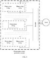
- FIG. 1 is a schematic diagram of an application scenario of a photovoltaic power generation system according to an embodiment of this application.
- the photovoltaic power generation system mainly includes at least one photovoltaic string, an inverter, and a grid among which connection relationships are shown in FIG. 1 .
- a photovoltaic string may be connected in parallel to another photovoltaic string and then connected to the inverter, or may be independently connected to the inverter.
- the inverter has a plurality of photovoltaic string input ends. Output of the photovoltaic string is connected to the input end of the inverter.
- a voltage of the input end of the inverter is referred to as a BUS voltage.
- An output end of the inverter is connected to the grid.
- the inverter implements direct current/alternating current conversion, to convert a direct current into an alternating current and output the alternating current to the grid.
- the inverter manages all optimizers in the photovoltaic string together, and a communication manner is power line carrier communication.
- an upper limit value corresponding to a voltage to ground of the optimizer may be set by the optimizer, or may be set by the inverter. No limitation is imposed in this application. It may be understood that in this application scenario, the inverter has a function of a control device.
- FIG. 2 is a schematic structural diagram of a photovoltaic string in the photovoltaic power generation system.
- Each photovoltaic string includes n photovoltaic modules (namely, a photovoltaic module 1, .., and a photovoltaic module n), where n is a positive integer greater than or equal to 2.
- n is a positive integer ranging from 5 to 25. In other words, a typical quantity of photovoltaic modules connected in series is 5 to 25.
- Each photovoltaic module includes a photovoltaic unit and an optimizer. As shown in FIG.
- a photovoltaic module 1 includes a photovoltaic unit 1 and an optimizer 1
- a photovoltaic module 2 includes a photovoltaic unit 2 and an optimizer 2
- a photovoltaic module n-1 includes a photovoltaic unit n-1 and an optimizer n-1
- a photovoltaic module n includes a photovoltaic unit n and an optimizer n.
- the photovoltaic unit includes at least one photovoltaic component, and the photovoltaic unit is connected to the optimizer. Output ends of all optimizers in the photovoltaic string are connected in series.
- a positive output end of an optimizer is connected to a negative output end of a previous optimizer, and a negative output end of the optimizer is connected to a positive output end of a next optimizer.
- a negative output end of the optimizer 1 is connected to a positive output end of the optimizer 2
- a negative output end of the optimizer 2 is connected to a positive output end of the optimizer 3
- all the optimizers are successively connected according to this rule.
- U1 to Un are respectively output voltages of all the optimizers
- Ulpe to Unpe are respectively output voltages to ground of all the optimizers
- Upe is a negative BUS voltage to ground
- PE is a ground point of the photovoltaic power generation system and is used as a reference point of each voltage to ground.
- each optimizer in this application may collect an output voltage to ground corresponding to the optimizer.
- the output voltage to ground is a voltage difference between a positive output end of the optimizer and the ground point of the photovoltaic power generation system.
- quantities of photovoltaic modules connected in series in photovoltaic strings may be different; powers of photovoltaic units may be different, including a power difference caused by different quantities of photovoltaic components, different serial or parallel connection manners, different models, or an external factor, for example, a photovoltaic component is lighted or blocked; and a photovoltaic unit or an optimizer may be removed due to a fault or added after recovery from a fault.
- FIG. 3 is a schematic diagram of another application scenario of a photovoltaic power generation system according to this application.
- the photovoltaic power generation system has an independent control device. Therefore, the control device instead of an inverter manages all photovoltaic strings together.
- an upper limit value corresponding to a voltage to ground of an optimizer may be set by the optimizer, or may be set by the control device. No limitation is imposed in this application.
- FIG. 4 is a schematic diagram of an embodiment of a control method for a photovoltaic power generation system according to an embodiment of this application. As shown in FIG. 4 , the control method for a photovoltaic power generation system in this embodiment of this application is specifically described as follows:
- a photovoltaic power generation system presets an upper limit value for each optimizer in the photovoltaic power generation system.
- the photovoltaic power generation system sets an upper limit value for each optimizer in the photovoltaic power generation system.
- the upper limit value is a maximum voltage value of an output voltage to ground of the optimizer. In other words, the output voltage to ground of the optimizer is less than or equal to the upper limit value.
- the output voltage to ground of the optimizer is a voltage difference between a positive output end of the optimizer and a ground point (namely, the foregoing point PE) of the photovoltaic power generation system.
- upper limit values are set for output voltages to ground of all the optimizers in the photovoltaic system. As shown in FIG. 2 , the output voltages to ground of the optimizers are respectively Ulpe to Unpe.
- the optimizer may first collect a voltage difference between a negative output end of the optimizer and the ground point of the photovoltaic power generation system, and then perform addition calculation based on the collected voltage difference and an output voltage of the optimizer, to obtain the output voltage to ground of the optimizer.
- the optimizer may directly collect the voltage difference between the positive output end of the optimizer and the node of the photovoltaic power generation system, to obtain the output voltage to ground. No limitation is imposed in this application.
- the optimizer in the photovoltaic power generation system sets the output voltage to ground of the optimizer.
- the photovoltaic power generation system further includes an inverter.
- the upper limit value of the output voltage to ground of the optimizer may be set by the optimizer, or may be set by the inverter. No limitation is imposed in this application. For other related descriptions, refer to the descriptions corresponding to FIG. 1 . Details are not described again.
- the photovoltaic power generation system further includes an inverter and a control device.
- the upper limit value of the output voltage to ground of the optimizer may be set by the optimizer or the control device.
- the optimizer is essentially a direct current/direct current converter, and may be isolated or non-isolated. No limitation is imposed in this application.
- a topology of the optimizer is not limited either, and may be any one of a buck buck topology, a boost topology, a buck-boost topology, or a boost-buck topology, or may be a combination of at least two of the topologies.
- a method for setting the output voltage to ground upper limit value of the optimizer may be specifically as follows:
- the voltage to ground upper limit value of the optimizer may be set by using a gradient method.
- the gradient method different output voltage to ground upper limit values are set based on physical locations of all the optimizers, and there is a sufficiently large headroom between an actual output voltage to ground value and the output voltage to ground upper limit value of each optimizer.
- the system described in the background is used as an example.
- a typical value may be 40 V.
- different systems have different typical values in an actual application scenario. This needs to depend on an actual case. No limitation is imposed in this application.
- For detailed descriptions of the gradient method refer to related descriptions in specific application scenarios corresponding to FIG. 5 and FIG. 6 . Details are not described herein.
- the voltage to ground upper limit value of the optimizer may be set by using a maximum method.
- the maximum method there is no need to know a physical location of each optimizer, output voltage to ground upper limit values of all the optimizers are set to a maximum value, and a headroom between an actual output voltage to ground value and the output voltage to ground upper limit value of each optimizer falls within a preset range, for example, 40 V to 390 V.
- 40 V to 390 V herein is also given by using the system described in the background as an example. No limitation is imposed in this application either.
- the method for setting the output voltage to ground upper limit value of the optimizer may be another method that can achieve same technical effects, or may be a combination of a plurality of methods. No limitation is imposed in this application.
- the photovoltaic power generation system limits an output voltage to ground of a target optimizer based on an upper limit value corresponding to the target optimizer.
- the photovoltaic power generation system limits the output voltage to ground of the target optimizer based on the output voltage to ground upper limit value corresponding to the target optimizer.
- the target optimizer is any optimizer in the photovoltaic power generation system. Essentially, the target optimizer in the photovoltaic power generation system limits the output voltage to ground of the target optimizer based on the output voltage to ground upper limit value corresponding to the target optimizer.
- the target optimizer limits the output voltage to ground of the target optimizer to the output voltage to ground upper limit value of the target optimizer.
- the optimizer in this embodiment of this application includes a voltage to ground sampling circuit, and the voltage to ground sampling circuit has a function of collecting the voltage difference between the output end of the optimizer and the ground point of the photovoltaic power generation system.
- the optimizer having a voltage to ground collection function provides important hardware support for implementing the control method for a photovoltaic power generation system in this application.
- the photovoltaic power generation system sets an upper limit value corresponding to the output voltage to ground for each converter in the system, and the photovoltaic power generation control system limits an output voltage to ground of a converter based on an upper limit value corresponding to the output voltage to ground of the converter.
- the output voltage to ground is not an output voltage. Because output ends of the converters are connected in series, an output voltage to ground of a converter is related to both an output voltage of the converter and an output voltage to ground of another converter in a same photovoltaic string.
- a BUS voltage is a sum of output voltages of converters in a same photovoltaic string. In other words, an output voltage to ground can directly reflect the BUS voltage, but an output voltage cannot directly reflect the BUS voltage.
- a maximum value of an output voltage upper limit value of each converter can reach a BUS voltage upper limit value of the photovoltaic string.
- the optimizer can obtain a larger voltage headroom after the output voltage to ground is set, so that in an abnormal scenario in which a photovoltaic component is blocked, each optimizer in the photovoltaic power generation system can work in an MPPT state. Therefore, the control method for a photovoltaic power generation system in this application can effectively reduce a photovoltaic energy loss in the photovoltaic power generation system.
- control method for a photovoltaic power generation system in this embodiment of this application is specifically described as follows:
- FIG. 5 is a schematic scenario diagram of a photovoltaic power generation system in a normal working scenario.
- the photovoltaic power generation system includes a plurality of photovoltaic strings such as a photovoltaic string A and a photovoltaic string B.
- the following is described by using the string A as an example. Descriptions of another photovoltaic string are similar to those of the photovoltaic string A, and details are not described herein again.
- a quantity of photovoltaic modules connected in series in the photovoltaic string A is 8, and a maximum power point of each photovoltaic unit is 200 W. 2. If a conducting wire loss is ignored, conversion efficiency of an optimizer is 100%. 3. An inverter sets a BUS voltage reference value to 400 V and a BUS voltage upper limit value to 440 V that is less than a system voltage level 600 V.
- U1 to U8 are successively output voltages of an optimizer 1 to an optimizer 8.
- Ulpe to U8pe are successively output voltages to ground of output voltages of the optimizer 1 to the optimizer 8.
- Upe is a negative BUS voltage to ground and is a fixed value, and may be determined based on an initial state.
- PE is a ground reference point of the photovoltaic power generation system, and an electric potential at the point is 0 V.
- an output power of the inverter is not limited and the inverter is normally connected to a grid for power generation, all the optimizers work in an MPPT state, and a BUS voltage remains at the BUS voltage reference value 400 V
- the output voltages to ground of the optimizer 1 to the optimizer 8 are successively: 400 V + Upe, 350 V + Upe, 300 V + Upe, 250 V + Upe, 200 V + Upe, 150 V + Upe, 100 V + Upe, and 50 V + Upe.
- output voltage to ground upper limit values of the optimizer 1 to the optimizer 8 may be successively set to 440 V + Upe, 390 V + Upe, 340 V + Upe, 290 V + Upe, 240 V + Upe, 190 V + Upe, 140 V + Upe, and 90 V + Upe based on a location of each optimizer in the photovoltaic string A and by using a gradient method.
- output voltage to ground upper limit values of the optimizers are set by using a maximum method, and the output voltage to ground upper limit values of the optimizer 1 to the optimizer 8 may be all set to a maximum value: 440 V + Upe.
- the output voltages to ground of the optimizer 1 to the optimizer 8 are all less than the output voltage to ground upper limit values corresponding to the optimizer 1 to the optimizer 8, and a voltage headroom between the output voltage to ground and the output voltage to ground falls within a range of 40 V to 390 V.
- FIG. 6 is a schematic scenario diagram of a photovoltaic power generation system in an abnormal working scenario.
- the photovoltaic unit 7 in the photovoltaic string A is blocked, and electric energy generated by the photovoltaic unit 7 is reduced. Consequently, an output power of the optimizer 7 is decreased to 40 W.
- the BUS voltage of the inverter remains at the BUS voltage reference value 400 V. It can be learned from the foregoing formula 1 that, in this case, the current Is is decreased from original 4 A to 3.6 A.
- the optimizer 1 to the optimizer 8 in the photovoltaic string A all work in the MPPT state, and there is no photovoltaic energy loss.
- An output voltage to ground value is entirely adjusted by the photovoltaic string A automatically, without active intervention of the photovoltaic power generation system.
- the abnormal working scenario further includes: strings in which different quantities of photovoltaic modules are connected in series are connected in parallel, components having different powers in a string are connected in series, some components are removed due to a fault or added after recovery from a fault, an output power of the inverter is limited or the inverter is shut down, and the like.
- all the optimizers in this application work in the MPPT state.
- the other abnormal working scenarios refer to the descriptions of the abnormal working scenario in which the photovoltaic unit is blocked.
- the other abnormal working scenarios are not enumerated one by one herein.
- the output voltage to ground upper limit value is set for each optimizer, and a voltage headroom between the output voltage to ground upper limit value and a normal output voltage to ground is dozens of volts or even hundreds of volts.
- a dynamic adjustment process an actual output voltage to ground of the optimizer does not reach the output voltage to ground upper limit value, and the optimizer does not exit the MPPT state to enter a power limited state. Therefore, in the system, for any scenario in which a photovoltaic component is blocked, faulty, or the like, the entire dynamic adjustment process requires no active intervention of the system, and there is no photovoltaic energy loss.
- the output voltage to ground upper limit value of the optimizer is initially set, any scenario in which a photovoltaic component is blocked, faulty, or the like can be effectively handled, and the output voltage to ground upper limit value does not need to be adjusted through active intervention of the system. Therefore, the output voltage to ground upper limit value of the optimizer only needs to be initially set, and does not need to be dynamically adjusted.
- the output voltage to ground upper limit value of the optimizer is directly corresponding to the BUS voltage, and a difference between the two values is only the negative BUS voltage to ground.
- a sum of output voltages of all optimizers in a single string is corresponding to the BUS voltage, and an output voltage of a single optimizer cannot reflect the BUS voltage. Therefore, controlling the output voltage to ground upper limit value of the optimizer is directly controlling the BUS voltage upper limit value.
- the disclosed system, apparatus, and method may be implemented in other manners.
- the described apparatus embodiment is only an example.
- the unit division is only logical function division and may be other division in actual implementation.
- a plurality of units or components may be combined or integrated into another system, or some features may be ignored or not performed.
- the displayed or discussed mutual couplings or direct couplings or communication connections may be implemented by using some interfaces.
- the indirect couplings or communication connections between the apparatuses or units may be implemented in electrical, mechanical, or other forms.
- the units described as separate parts may or may not be physically separate, and parts displayed as units may or may not be physical units, may be located in one position, or may be distributed on a plurality of network units. Some or all of the units may be selected based on actual requirements to achieve the objectives of the solutions in the embodiments.
- function units in the embodiments of this application may be integrated into one processing unit, or each of the units may exist alone physically, or two or more units are integrated into one unit.
- the integrated unit may be implemented in a form of hardware, or may be implemented in a form of a software function unit.
- the integrated unit When the integrated unit is implemented in the form of a software function unit and sold or used as an independent product, the integrated unit may be stored in a computer readable storage medium. Based on such an understanding, the technical solutions in this application essentially, or the part contributing to the prior art, or all or some of the technical solutions may be implemented in a form of a software product.
- the computer software product is stored in a storage medium and includes several instructions for instructing a computer device (which may be a personal computer, a server, a network device, or the like) to perform all or some of the steps of the methods described in the embodiments of this application.
- the foregoing storage medium includes: any medium that can store program code, such as a USB flash drive, a removable hard disk, a read-only memory (ROM, Read-Only Memory), a random access memory (RAM, Random Access Memory), a magnetic disk, or an optical disc.
- program code such as a USB flash drive, a removable hard disk, a read-only memory (ROM, Read-Only Memory), a random access memory (RAM, Random Access Memory), a magnetic disk, or an optical disc.
Landscapes
- Engineering & Computer Science (AREA)
- Power Engineering (AREA)
- Life Sciences & Earth Sciences (AREA)
- Sustainable Development (AREA)
- Sustainable Energy (AREA)
- Physics & Mathematics (AREA)
- Electromagnetism (AREA)
- General Physics & Mathematics (AREA)
- Radar, Positioning & Navigation (AREA)
- Automation & Control Theory (AREA)
- Control Of Electrical Variables (AREA)
- Supply And Distribution Of Alternating Current (AREA)
Abstract
Description
- This application claims priority to Chinese Patent Application No.
201710633242.8 - This application relates to the field of photovoltaic power generation, and in particular, to a photovoltaic power generation control method and a photovoltaic power generation system.
- In a photovoltaic power generation system using optimizers and a distributed maximum power point tracking (MPPT) technology, a measure needs to be taken to ensure that a sum (which is referred to as a BUS voltage for short) of output voltages of all the optimizers in the photovoltaic power generation system is always less than a system voltage to ensure that the photovoltaic power generation system can normally work in any scenario. When an output voltage of an optimizer is less than an output voltage upper limit value, the optimizer works in an MPPT state, and no photovoltaic energy loss occurs. When an output voltage of an optimizer is greater than or equal to an output voltage upper limit value, the optimizer works in a power limited state, a photovoltaic energy loss occurs. In this case, the photovoltaic power generation system needs to adjust the output voltage upper limit value of the optimizer, to make the optimizer return from the power limited state to the MPPT state.
- An existing assurance measure is setting a BUS voltage upper limit value. The BUS voltage upper limit value ranges between a normal working voltage and the system voltage. For example, if the normal working voltage is 400 V and the system voltage is 600 V, the BUS voltage upper limit value may be 110% of the normal working voltage, namely, 440 V. Assuming that a single photovoltaic string includes eight optimizers connected in series, a normal output voltage of each optimizer is 50 V, and an output voltage upper limit value is 55 V.
- In the existing assurance measure, a BUS voltage upper limit value is set for a photovoltaic string. Because all optimizers in a single photovoltaic string are connected in series, and a BUS voltage is equivalent to a sum of output voltages of all the optimizers, a sum of output voltage upper limit values of all the optimizers is equivalent to the BUS voltage upper limit value. In other words, a voltage headroom between a normal working voltage and the output voltage upper limit value of each optimizer is relatively small, for example, 5 V. In addition, when the BUS voltage upper limit value remains unchanged, the foregoing voltage headroom value of each optimizer is decreased as a quantity of optimizers is increased. When a photovoltaic component corresponding to an optimizer is blocked, output voltages of some optimizers reach output voltage upper limit values because the voltage headroom of each optimizer is relatively small. Consequently, the some optimizers work in the power limited state, causing a photovoltaic energy loss. In this case, the photovoltaic power generation system needs to increase the output voltage upper limit values of the optimizers, to make the converters exit the power limited state and enter the MPPT state to work.
- Embodiments of this application provide a photovoltaic power generation control method and a photovoltaic power generation system, to reduce a photovoltaic energy loss in the photovoltaic power generation system.
- According to a first aspect, an embodiment of this application provides a photovoltaic power generation control method. The method is applied to a photovoltaic power generation system. The photovoltaic power generation system includes at least one photovoltaic string. Each photovoltaic string includes at least one photovoltaic module. Each photovoltaic module includes a photovoltaic unit and a converter (also referred to as an optimizer). The photovoltaic unit and the converter in each photovoltaic module are connected, that is, an output end of the photovoltaic unit is connected to an input end of the converter. In addition, converters in a same photovoltaic string are connected in series, that is, output ends of the converters are connected in series. The method includes the following:
- First, the photovoltaic power generation system sets an upper limit value for each converter in the photovoltaic power generation system. In other words, the photovoltaic power generation system sets upper limit values for all the converters in the system. The upper limit value is a maximum voltage value of an output voltage to ground of the converter, and the output voltage to ground is a voltage difference between a positive output end of the converter and a ground point of the photovoltaic power generation system. It should be understood that, the upper limit value is not an output voltage upper limit value. Then, the photovoltaic power generation system limits an output voltage to ground of a target converter based on an upper limit value corresponding to the target converter. The target converter is any converter in the photovoltaic power generation system. In other words, the photovoltaic power generation system limits the output voltage to ground of each converter based on the upper limit value corresponding to the converter.
- It can be learned from the foregoing technical solution that this embodiment of this application has the following advantages:
- In this application, the photovoltaic power generation system sets an upper limit value corresponding to the output voltage to ground for each converter in the system, and the photovoltaic power generation control system limits an output voltage to ground of a converter based on an upper limit value corresponding to the output voltage to ground of the converter. It should be understood that, the output voltage to ground is not an output voltage. Because output ends of the converters are connected in series, an output voltage to ground of a converter is related to both an output voltage of the converter and an output voltage to ground of another converter in a same photovoltaic string. A BUS voltage is a sum of output voltages of converters in a same photovoltaic string. In other words, an output voltage to ground can directly reflect the BUS voltage, but an output voltage cannot directly reflect the BUS voltage. If a corresponding upper limit value is set for the output voltage to ground of the converter, a maximum value of an output voltage upper limit value of each converter can reach a BUS voltage upper limit value of the photovoltaic string. Apparently, the optimizer can obtain a larger voltage headroom after the output voltage to ground is set, so that in an abnormal scenario in which a photovoltaic component is blocked, each optimizer in the photovoltaic power generation system can work in an MPPT state. Therefore, the control method for a photovoltaic power generation system in this application can effectively reduce a photovoltaic energy loss in the photovoltaic power generation system.
- With reference to the first aspect of the embodiments of this application, in a first implementation of the first aspect of the embodiments of this application, the upper limit value corresponding to the target converter is set by the target converter.
- With reference to the first aspect of the embodiments of this application, in a second implementation of the first aspect of the embodiments of this application, the photovoltaic power generation system further includes a control device, and the upper limit value corresponding to the target converter is centrally set by the control device.
- With reference to the second implementation of the first aspect of the embodiments of this application, in a third implementation of the first aspect of the embodiments of this application, the control device includes an inverter.
- With reference to the first aspect of the embodiments of this application, the first implementation of the first aspect of the embodiments of this application, or the second implementation of the first aspect of the embodiments of this application, in a fourth implementation of the first aspect of the embodiments of this application, the output voltage to ground upper limit value corresponding to the target converter may be calculated by using a gradient method and/or a maximum method. Certainly, another method or a combination of other methods may be used to set the output voltage to ground of the converter. No limitation is imposed in this application.
- With reference to the first aspect of the embodiments of this application, in a fifth implementation of the first aspect of the embodiments of this application, the limiting, by the photovoltaic power generation system, an output voltage to ground of a target converter based on an output voltage to ground upper limit value corresponding to the target converter includes:
when the output voltage to ground of the target converter is greater than the output voltage to ground upper limit value of the target converter, limiting, by the photovoltaic power generation system, the output voltage to ground of the target converter to the output voltage to ground upper limit value of the target converter. - With reference to any one of the first aspect of the embodiments of this application, or the first implementation of the first aspect to the fifth implementation of the first aspect of the embodiments of this application, in a sixth implementation of the first aspect of the embodiments of this application, the converter is a direct current/direct current converter, and a topology of the converter includes: a buck buck topology, a boost topology, a buck-boost topology, or a boost-buck topology.
- With reference to any one of the first aspect of the embodiments of this application, or the first implementation of the first aspect to the sixth implementation of the first aspect of the embodiments of this application, in a seventh implementation of the first aspect of the embodiments of this application, the converter includes an isolated converter or a non-isolated converter.
- According to a second aspect, an embodiment of this application provides a photovoltaic power generation system, where the photovoltaic power generation system includes at least one photovoltaic string, each photovoltaic string includes at least one photovoltaic module, each photovoltaic module includes a photovoltaic unit and a converter, the photovoltaic unit and the converter in each photovoltaic module are connected, converters in a same photovoltaic string are connected in series, and the photovoltaic power generation system is configured to perform the operations according to
claim - Related descriptions of beneficial effects of the second aspect are similar to descriptions of beneficial effects of the first aspect. For details, refer to the related descriptions in the first aspect. Details are not described herein again.
- With reference to the second aspect of the embodiments of this application, in a first implementation of the second aspect of the embodiments of this application, each photovoltaic unit includes at least one photovoltaic component, and a connection relationship between photovoltaic components in the at least one photovoltaic component is not limited.
- With reference to the second aspect of the embodiments of this application, in a second implementation of the second aspect of the embodiments of this application, the photovoltaic power generation system further includes a control device, and the photovoltaic power generation system is configured to perform the operations according to any one of claims 3 to 8.
- According to a third aspect, an embodiment of this application provides a converter, where the converter includes a voltage to ground sampling circuit, the voltage to ground sampling circuit is located at an output end of the converter, and the voltage to ground sampling circuit is configured to collect a voltage to ground of a positive output end of the converter or a negative output end of the converter.
-
-
FIG 1 is a schematic diagram of an application scenario of a photovoltaic power generation system according to an embodiment of this application; -
FIG. 2 is a schematic structural diagram of a photovoltaic string in a photovoltaic power generation system; -
FIG. 3 is a schematic diagram of another application scenario of a photovoltaic power generation system according to an embodiment of this application; -
FIG. 4 is a schematic diagram of an embodiment of a control method for a photovoltaic power generation system according to an embodiment of this application; -
FIG. 5 is a schematic scenario diagram of a photovoltaic power generation system in a normal working scenario; and -
FIG. 6 is a schematic scenario diagram of a photovoltaic power generation system in an abnormal working scenario. - Embodiments of this application provide a photovoltaic power generation control method and a photovoltaic power generation system, to reduce a photovoltaic energy loss in the photovoltaic power generation system.
- In the specification, claims, and accompanying drawings of this application, the terms "first", "second", "third", "fourth", and the like (if existent) are intended to distinguish between similar objects but do not necessarily indicate a specific order or sequence. It should be understood that, the data used in such a way is interchangeable in proper circumstances, so that the embodiments described herein can be implemented in other orders than the order illustrated or described herein. Moreover, the terms "include", "contain" and any other variants mean to cover the non-exclusive inclusion, for example, a process, method, system, product, or device that includes a list of steps or units is not necessarily limited to those expressly listed steps or units, but may include other steps or units not expressly listed or inherent to such a process, method, product, or device.
- To help understand the embodiments of this application, in this application, a photovoltaic power generation system and a control method for a photovoltaic power generation system in this application and a specific application scenario of the control method are successively described below in detail by using specific embodiments. In addition, it should be noted that an optimizer mentioned in the following embodiments is a converter.
- First, the photovoltaic power generation system in the embodiments of this application is specifically described as follows:
-
FIG. 1 is a schematic diagram of an application scenario of a photovoltaic power generation system according to an embodiment of this application. The photovoltaic power generation system mainly includes at least one photovoltaic string, an inverter, and a grid among which connection relationships are shown inFIG. 1 . A photovoltaic string may be connected in parallel to another photovoltaic string and then connected to the inverter, or may be independently connected to the inverter. In addition, the inverter has a plurality of photovoltaic string input ends. Output of the photovoltaic string is connected to the input end of the inverter. A voltage of the input end of the inverter is referred to as a BUS voltage. An output end of the inverter is connected to the grid. The inverter implements direct current/alternating current conversion, to convert a direct current into an alternating current and output the alternating current to the grid. In this application scenario, the inverter manages all optimizers in the photovoltaic string together, and a communication manner is power line carrier communication. In this case, an upper limit value corresponding to a voltage to ground of the optimizer may be set by the optimizer, or may be set by the inverter. No limitation is imposed in this application. It may be understood that in this application scenario, the inverter has a function of a control device. -
FIG. 2 is a schematic structural diagram of a photovoltaic string in the photovoltaic power generation system. Each photovoltaic string includes n photovoltaic modules (namely, aphotovoltaic module 1, .., and a photovoltaic module n), where n is a positive integer greater than or equal to 2. Atypical value of n is a positive integer ranging from 5 to 25. In other words, a typical quantity of photovoltaic modules connected in series is 5 to 25. Each photovoltaic module includes a photovoltaic unit and an optimizer. As shown inFIG. 2 , aphotovoltaic module 1 includes aphotovoltaic unit 1 and anoptimizer 1, aphotovoltaic module 2 includes aphotovoltaic unit 2 and anoptimizer 2, ..., a photovoltaic module n-1 includes a photovoltaic unit n-1 and an optimizer n-1, and a photovoltaic module n includes a photovoltaic unit n and an optimizer n. The photovoltaic unit includes at least one photovoltaic component, and the photovoltaic unit is connected to the optimizer. Output ends of all optimizers in the photovoltaic string are connected in series. That is, a positive output end of an optimizer is connected to a negative output end of a previous optimizer, and a negative output end of the optimizer is connected to a positive output end of a next optimizer. For example, as shown inFIG. 1 , a negative output end of theoptimizer 1 is connected to a positive output end of theoptimizer 2, a negative output end of theoptimizer 2 is connected to a positive output end of the optimizer 3, and all the optimizers are successively connected according to this rule. - In addition, it should be noted that, U1 to Un are respectively output voltages of all the optimizers, Ulpe to Unpe are respectively output voltages to ground of all the optimizers, Upe is a negative BUS voltage to ground, and PE is a ground point of the photovoltaic power generation system and is used as a reference point of each voltage to ground. In addition, each optimizer in this application may collect an output voltage to ground corresponding to the optimizer. The output voltage to ground is a voltage difference between a positive output end of the optimizer and the ground point of the photovoltaic power generation system.
- It should further be noted that, in the photovoltaic power generation system in this application, quantities of photovoltaic modules connected in series in photovoltaic strings may be different; powers of photovoltaic units may be different, including a power difference caused by different quantities of photovoltaic components, different serial or parallel connection manners, different models, or an external factor, for example, a photovoltaic component is lighted or blocked; and a photovoltaic unit or an optimizer may be removed due to a fault or added after recovery from a fault.
-
FIG. 3 is a schematic diagram of another application scenario of a photovoltaic power generation system according to this application. In the application scenario shown inFIG. 3 , the photovoltaic power generation system has an independent control device. Therefore, the control device instead of an inverter manages all photovoltaic strings together. Similarly, in this case, an upper limit value corresponding to a voltage to ground of an optimizer may be set by the optimizer, or may be set by the control device. No limitation is imposed in this application. - In addition, for related descriptions of
FIG. 3 , refer to the related descriptions ofFIG. 1 . Details are not described herein again. - Second,
FIG. 4 is a schematic diagram of an embodiment of a control method for a photovoltaic power generation system according to an embodiment of this application. As shown inFIG. 4 , the control method for a photovoltaic power generation system in this embodiment of this application is specifically described as follows: - 401. A photovoltaic power generation system presets an upper limit value for each optimizer in the photovoltaic power generation system.
- In this embodiment, the photovoltaic power generation system sets an upper limit value for each optimizer in the photovoltaic power generation system. The upper limit value is a maximum voltage value of an output voltage to ground of the optimizer. In other words, the output voltage to ground of the optimizer is less than or equal to the upper limit value. It is not difficult to understand that, the output voltage to ground of the optimizer is a voltage difference between a positive output end of the optimizer and a ground point (namely, the foregoing point PE) of the photovoltaic power generation system. It may be understood that in this step, upper limit values are set for output voltages to ground of all the optimizers in the photovoltaic system. As shown in
FIG. 2 , the output voltages to ground of the optimizers are respectively Ulpe to Unpe. - In some embodiments of this application, the optimizer may first collect a voltage difference between a negative output end of the optimizer and the ground point of the photovoltaic power generation system, and then perform addition calculation based on the collected voltage difference and an output voltage of the optimizer, to obtain the output voltage to ground of the optimizer. In addition, the optimizer may directly collect the voltage difference between the positive output end of the optimizer and the node of the photovoltaic power generation system, to obtain the output voltage to ground. No limitation is imposed in this application.
- In addition, for an entity that sets the output voltage to ground of the optimizer, the following application scenarios may exist.
- Optionally, in a possible application scenario, the optimizer in the photovoltaic power generation system sets the output voltage to ground of the optimizer.
- Optionally, in another possible application scenario, for example, in the application scenario shown in
FIG. 1 , the photovoltaic power generation system further includes an inverter. In this case, the upper limit value of the output voltage to ground of the optimizer may be set by the optimizer, or may be set by the inverter. No limitation is imposed in this application. For other related descriptions, refer to the descriptions corresponding toFIG. 1 . Details are not described again. - Optionally, in still another possible application scenario, for example, in the application scenario shown in
FIG. 3 , the photovoltaic power generation system further includes an inverter and a control device. In this case, the upper limit value of the output voltage to ground of the optimizer may be set by the optimizer or the control device. No limitation is imposed in this application. For other related descriptions, refer to the descriptions corresponding toFIG. 3 . Details are not described again. - The optimizer is essentially a direct current/direct current converter, and may be isolated or non-isolated. No limitation is imposed in this application. A topology of the optimizer is not limited either, and may be any one of a buck buck topology, a boost topology, a buck-boost topology, or a boost-buck topology, or may be a combination of at least two of the topologies.
- Further, a method for setting the output voltage to ground upper limit value of the optimizer may be specifically as follows:
- Optionally, in a possible setting manner, the voltage to ground upper limit value of the optimizer may be set by using a gradient method. In the gradient method, different output voltage to ground upper limit values are set based on physical locations of all the optimizers, and there is a sufficiently large headroom between an actual output voltage to ground value and the output voltage to ground upper limit value of each optimizer. The system described in the background is used as an example. A typical value may be 40 V. Certainly, it should be noted that, different systems have different typical values in an actual application scenario. This needs to depend on an actual case. No limitation is imposed in this application. For detailed descriptions of the gradient method, refer to related descriptions in specific application scenarios corresponding to
FIG. 5 andFIG. 6 . Details are not described herein. - Optionally, in another possible setting manner, the voltage to ground upper limit value of the optimizer may be set by using a maximum method. In the maximum method, there is no need to know a physical location of each optimizer, output voltage to ground upper limit values of all the optimizers are set to a maximum value, and a headroom between an actual output voltage to ground value and the output voltage to ground upper limit value of each optimizer falls within a preset range, for example, 40 V to 390 V. For detailed descriptions of the maximum method, refer to related descriptions in specific application scenarios corresponding to
FIG. 5 andFIG. 6 . Details are not described herein. In addition, "40 V to 390 V" herein is also given by using the system described in the background as an example. No limitation is imposed in this application either. - In addition, it should be noted that, the method for setting the output voltage to ground upper limit value of the optimizer may be another method that can achieve same technical effects, or may be a combination of a plurality of methods. No limitation is imposed in this application.
- 402. The photovoltaic power generation system limits an output voltage to ground of a target optimizer based on an upper limit value corresponding to the target optimizer.
- In this embodiment, the photovoltaic power generation system limits the output voltage to ground of the target optimizer based on the output voltage to ground upper limit value corresponding to the target optimizer. The target optimizer is any optimizer in the photovoltaic power generation system. Essentially, the target optimizer in the photovoltaic power generation system limits the output voltage to ground of the target optimizer based on the output voltage to ground upper limit value corresponding to the target optimizer.
- Optionally, in a possible implementation, if the output voltage to ground of the target optimizer is greater than the output voltage to ground upper limit value corresponding to the target optimizer, the target optimizer limits the output voltage to ground of the target optimizer to the output voltage to ground upper limit value of the target optimizer.
- In addition, it should be noted that, the optimizer in this embodiment of this application includes a voltage to ground sampling circuit, and the voltage to ground sampling circuit has a function of collecting the voltage difference between the output end of the optimizer and the ground point of the photovoltaic power generation system. The optimizer having a voltage to ground collection function provides important hardware support for implementing the control method for a photovoltaic power generation system in this application.
- In this embodiment, the photovoltaic power generation system sets an upper limit value corresponding to the output voltage to ground for each converter in the system, and the photovoltaic power generation control system limits an output voltage to ground of a converter based on an upper limit value corresponding to the output voltage to ground of the converter. It should be understood that, the output voltage to ground is not an output voltage. Because output ends of the converters are connected in series, an output voltage to ground of a converter is related to both an output voltage of the converter and an output voltage to ground of another converter in a same photovoltaic string. A BUS voltage is a sum of output voltages of converters in a same photovoltaic string. In other words, an output voltage to ground can directly reflect the BUS voltage, but an output voltage cannot directly reflect the BUS voltage. If a corresponding upper limit value is set for the output voltage to ground of the converter, a maximum value of an output voltage upper limit value of each converter can reach a BUS voltage upper limit value of the photovoltaic string. Apparently, the optimizer can obtain a larger voltage headroom after the output voltage to ground is set, so that in an abnormal scenario in which a photovoltaic component is blocked, each optimizer in the photovoltaic power generation system can work in an MPPT state. Therefore, the control method for a photovoltaic power generation system in this application can effectively reduce a photovoltaic energy loss in the photovoltaic power generation system.
- Finally, with reference to specific application scenarios, the control method for a photovoltaic power generation system in this embodiment of this application is specifically described as follows:
-
FIG. 5 is a schematic scenario diagram of a photovoltaic power generation system in a normal working scenario. The photovoltaic power generation system includes a plurality of photovoltaic strings such as a photovoltaic string A and a photovoltaic string B. The following is described by using the string A as an example. Descriptions of another photovoltaic string are similar to those of the photovoltaic string A, and details are not described herein again. - To simplify calculation, the following assumptions are made for the photovoltaic string A shown in
FIG. 5 :1 . A quantity of photovoltaic modules connected in series in the photovoltaic string A is 8, and a maximum power point of each photovoltaic unit is 200 W. 2. If a conducting wire loss is ignored, conversion efficiency of an optimizer is 100%. 3. An inverter sets a BUS voltage reference value to 400 V and a BUS voltage upper limit value to 440 V that is less than a system voltage level 600 V. - As shown in
FIG. 5 , U1 to U8 are successively output voltages of anoptimizer 1 to anoptimizer 8. Ulpe to U8pe are successively output voltages to ground of output voltages of theoptimizer 1 to theoptimizer 8. Upe is a negative BUS voltage to ground and is a fixed value, and may be determined based on an initial state. PE is a ground reference point of the photovoltaic power generation system, and an electric potential at the point is 0 V. - If an output power of the inverter is not limited and the inverter is normally connected to a grid for power generation, all the optimizers work in an MPPT state, and a BUS voltage remains at the BUS voltage reference value 400 V, an input current of the inverter is as follows: A current Is that is input by the photovoltaic string A to the inverter is obtained based on the following
formula 1, where Pn represents a power of an nth photovoltaic component, and Ubus is the BUS voltage:
- A formula for calculating an output voltage Un of each optimizer is a
formula 2 that is shown as follows:
- It can be learned from the foregoing assumptions that for each optimizer (the
optimizer 1 to theoptimizer 8 in the figure) in the photovoltaic string A, an output power is 200 W, an output voltage is 50 V, and a current Is is 4 A. - It can be learned from
FIG. 5 that, the output voltages to ground of the eight optimizers in the photovoltaic string A are successively as follows:


- Therefore, it can be learned that in the normal working scenario, the output voltages to ground of the
optimizer 1 to theoptimizer 8 are successively: 400 V + Upe, 350 V + Upe, 300 V + Upe, 250 V + Upe, 200 V + Upe, 150 V + Upe, 100 V + Upe, and 50 V + Upe. - Because it is assumed that the BUS voltage upper limit value is 440 V, the following setting may be performed. First, output voltage to ground upper limit values of the
optimizer 1 to theoptimizer 8 may be successively set to 440 V + Upe, 390 V + Upe, 340 V + Upe, 290 V + Upe, 240 V + Upe, 190 V + Upe, 140 V + Upe, and 90 V + Upe based on a location of each optimizer in the photovoltaic string A and by using a gradient method. - It can be apparently learned that, when the output voltage to ground upper limit values of the optimizers are set by using the gradient method, the output voltages to ground of the
optimizer 1 to theoptimizer 8 are all less than the output voltage to ground upper limit values corresponding to theoptimizer 1 to theoptimizer 8, and a voltage headroom between the output voltage to ground and the output voltage to ground is approximately 40 V. Therefore, theoptimizer 1 to theoptimizer 8 in the photovoltaic string A all work in the MPPT state, and there is no photovoltaic energy loss. - Second, output voltage to ground upper limit values of the optimizers are set by using a maximum method, and the output voltage to ground upper limit values of the
optimizer 1 to theoptimizer 8 may be all set to a maximum value: 440 V + Upe. Similarly, it is apparent that the output voltages to ground of theoptimizer 1 to theoptimizer 8 are all less than the output voltage to ground upper limit values corresponding to theoptimizer 1 to theoptimizer 8, and a voltage headroom between the output voltage to ground and the output voltage to ground falls within a range of 40 V to 390 V. -
FIG. 6 is a schematic scenario diagram of a photovoltaic power generation system in an abnormal working scenario. Thephotovoltaic unit 7 in the photovoltaic string A is blocked, and electric energy generated by thephotovoltaic unit 7 is reduced. Consequently, an output power of theoptimizer 7 is decreased to 40 W. Ideally, the BUS voltage of the inverter remains at the BUS voltage reference value 400 V. It can be learned from the foregoingformula 1 that, in this case, the current Is is decreased from original 4 A to 3.6 A. It can be learned from the foregoingformula 2 that, output voltages of normal optimizers (including theoptimizer 1 to the optimizer 6 and the optimizer 8) are increased from 50 V to 55.56 V, and an output voltage of an abnormal optimizer (the optimizer 7) is decreased from 50 V to 11.11 V. - It can be learned from the foregoing analysis that in the abnormal working scenario, the output voltages to ground of the
optimizer 1 to theoptimizer 8 are successively: 400.03 V + Upe, 344.47 V + Upe, 288.91 V + Upe, 233.25 V + Upe, 177.79 V + Upe, 122.23 V + Upe, 66.67 V + Upe, and 55.56 V + Upe. It can be easily learned that, after thephotovoltaic unit 7 is blocked, an output voltage to ground upper limit value that is set by using the gradient method and an output voltage to ground upper limit value that is set by using the maximum method each are greater than a corresponding output voltage to ground. Therefore, in the abnormal working scenario, theoptimizer 1 to theoptimizer 8 in the photovoltaic string A all work in the MPPT state, and there is no photovoltaic energy loss. An output voltage to ground value is entirely adjusted by the photovoltaic string A automatically, without active intervention of the photovoltaic power generation system. - In addition, it should be noted that, in addition to a case in which the photovoltaic unit is blocked, the abnormal working scenario further includes: strings in which different quantities of photovoltaic modules are connected in series are connected in parallel, components having different powers in a string are connected in series, some components are removed due to a fault or added after recovery from a fault, an output power of the inverter is limited or the inverter is shut down, and the like. In the foregoing abnormal working scenario, all the optimizers in this application work in the MPPT state. For descriptions of other abnormal working scenarios, refer to the descriptions of the abnormal working scenario in which the photovoltaic unit is blocked. The other abnormal working scenarios are not enumerated one by one herein.
- For the photovoltaic power generation system in this application, the output voltage to ground upper limit value is set for each optimizer, and a voltage headroom between the output voltage to ground upper limit value and a normal output voltage to ground is dozens of volts or even hundreds of volts. In a dynamic adjustment process, an actual output voltage to ground of the optimizer does not reach the output voltage to ground upper limit value, and the optimizer does not exit the MPPT state to enter a power limited state. Therefore, in the system, for any scenario in which a photovoltaic component is blocked, faulty, or the like, the entire dynamic adjustment process requires no active intervention of the system, and there is no photovoltaic energy loss.
- Further, after the output voltage to ground upper limit value of the optimizer is initially set, any scenario in which a photovoltaic component is blocked, faulty, or the like can be effectively handled, and the output voltage to ground upper limit value does not need to be adjusted through active intervention of the system. Therefore, the output voltage to ground upper limit value of the optimizer only needs to be initially set, and does not need to be dynamically adjusted.
- Furthermore, the output voltage to ground upper limit value of the optimizer is directly corresponding to the BUS voltage, and a difference between the two values is only the negative BUS voltage to ground. However, a sum of output voltages of all optimizers in a single string is corresponding to the BUS voltage, and an output voltage of a single optimizer cannot reflect the BUS voltage. Therefore, controlling the output voltage to ground upper limit value of the optimizer is directly controlling the BUS voltage upper limit value.
- It may be clearly understood by persons skilled in the art that, for the purpose of convenient and brief description, for a detailed working process of the foregoing system, apparatus, and unit, refer to a corresponding process in the foregoing method embodiments, and details are not described herein again.
- In the several embodiments provided in this application, it should be understood that the disclosed system, apparatus, and method may be implemented in other manners. For example, the described apparatus embodiment is only an example. For example, the unit division is only logical function division and may be other division in actual implementation. For example, a plurality of units or components may be combined or integrated into another system, or some features may be ignored or not performed. In addition, the displayed or discussed mutual couplings or direct couplings or communication connections may be implemented by using some interfaces. The indirect couplings or communication connections between the apparatuses or units may be implemented in electrical, mechanical, or other forms.
- The units described as separate parts may or may not be physically separate, and parts displayed as units may or may not be physical units, may be located in one position, or may be distributed on a plurality of network units. Some or all of the units may be selected based on actual requirements to achieve the objectives of the solutions in the embodiments.
- In addition, function units in the embodiments of this application may be integrated into one processing unit, or each of the units may exist alone physically, or two or more units are integrated into one unit. The integrated unit may be implemented in a form of hardware, or may be implemented in a form of a software function unit.
- When the integrated unit is implemented in the form of a software function unit and sold or used as an independent product, the integrated unit may be stored in a computer readable storage medium. Based on such an understanding, the technical solutions in this application essentially, or the part contributing to the prior art, or all or some of the technical solutions may be implemented in a form of a software product. The computer software product is stored in a storage medium and includes several instructions for instructing a computer device (which may be a personal computer, a server, a network device, or the like) to perform all or some of the steps of the methods described in the embodiments of this application. The foregoing storage medium includes: any medium that can store program code, such as a USB flash drive, a removable hard disk, a read-only memory (ROM, Read-Only Memory), a random access memory (RAM, Random Access Memory), a magnetic disk, or an optical disc.
- The foregoing embodiments are only intended for describing the technical solutions in this application, but not for limiting this application. Although this application is described in detail with reference to the foregoing embodiments, persons of ordinary skill in the art should understand that they may still make modifications to the technical solutions described in the foregoing embodiments or make equivalent replacements to some technical features thereof, without departing from the scope of the technical solutions in the embodiments of this application.
Claims (12)
- A photovoltaic power generation control method, wherein the method is applied to a photovoltaic power generation system, the photovoltaic power generation system comprises at least one photovoltaic string, each photovoltaic string comprises at least one photovoltaic module, each photovoltaic module comprises a photovoltaic unit and a converter, the photovoltaic unit and the converter in each photovoltaic module are connected, converters in a same photovoltaic string are connected in series, and the method comprises:presetting, by the photovoltaic power generation system, an upper limit value for each converter in the photovoltaic power generation system, wherein the upper limit value is a maximum voltage value of an output voltage to ground of the converter, and the output voltage to ground is a voltage difference between a positive output end of the converter and a ground point of the photovoltaic power generation system; andlimiting, by the photovoltaic power generation system, an output voltage to ground of a target converter based on an upper limit value corresponding to the target converter, wherein the target converter is any converter in the photovoltaic power generation system.
- The photovoltaic power generation control method according to claim 1, wherein the upper limit value corresponding to the target converter is set by the target converter.
- The photovoltaic power generation control method according to claim 1, wherein the photovoltaic power generation system further comprises a control device, and the upper limit value corresponding to the target converter is centrally set by the control device.
- The photovoltaic power generation control method according to claim 3, wherein the control device comprises an inverter.
- The photovoltaic power generation control method according to any one of claims 1 to 3, wherein the upper limit value corresponding to the target converter is calculated by using a gradient method and/or a maximum method.
- The photovoltaic power generation control method according to claim 1, wherein the limiting, by the photovoltaic power generation system, an output voltage to ground of a target converter based on an upper limit value corresponding to the target converter comprises:
if the output voltage to ground of the target converter is greater than the upper limit value corresponding to the target converter, limiting, by the photovoltaic power generation system, the output voltage to ground of the target converter to the upper limit value corresponding to the target converter. - The photovoltaic power generation control method according to any one of claims 1 to 6, wherein the converter is a direct current/direct current converter, and a topology of the converter comprises: a buck topology, a boost topology, a buck-boost topology, or a boost-buck topology.
- The photovoltaic power generation control method according to any one of claims 1 to 7, wherein the converter comprises an isolated converter or a non-isolated converter.
- A photovoltaic power generation system, wherein the photovoltaic power generation system comprises at least one photovoltaic string, each photovoltaic string comprises at least one photovoltaic module, each photovoltaic module comprises a photovoltaic unit and a converter, the photovoltaic unit and the converter in each photovoltaic module are connected, converters in a same photovoltaic string are connected in series, and the photovoltaic power generation system is configured to perform the operations according to claim 1 or 2.
- The photovoltaic power generation system according to claim 9, wherein each photovoltaic unit comprises at least one photovoltaic component.
- The photovoltaic power generation system according to claim 9, wherein the photovoltaic power generation system further comprises a control device, and the photovoltaic power generation system is configured to perform the operations according to any one of claims 3 to 8.
- A converter, wherein the converter comprises a voltage to ground sampling circuit, the voltage to ground sampling circuit is located at an output end of the converter, and the voltage to ground sampling circuit is configured to collect a voltage to ground of a positive output end of the converter or a negative output end of the converter.
Applications Claiming Priority (2)
| Application Number | Priority Date | Filing Date | Title |
|---|---|---|---|
| CN201710633242.8A CN107528340B (en) | 2017-07-28 | 2017-07-28 | A photovoltaic power generation control method and photovoltaic power generation system |
| PCT/CN2018/096756 WO2019019992A1 (en) | 2017-07-28 | 2018-07-24 | Method for controlling photovoltaic power generation, and photovoltaic power generation system |
Publications (3)
| Publication Number | Publication Date |
|---|---|
| EP3629439A1 true EP3629439A1 (en) | 2020-04-01 |
| EP3629439A4 EP3629439A4 (en) | 2020-07-22 |
| EP3629439B1 EP3629439B1 (en) | 2023-09-06 |
Family
ID=60680424
Family Applications (1)
| Application Number | Title | Priority Date | Filing Date |
|---|---|---|---|
| EP18838910.0A Active EP3629439B1 (en) | 2017-07-28 | 2018-07-24 | Method for controlling photovoltaic power generation, and photovoltaic power generation system |
Country Status (4)
| Country | Link |
|---|---|
| US (1) | US11527892B2 (en) |
| EP (1) | EP3629439B1 (en) |
| CN (1) | CN107528340B (en) |
| WO (1) | WO2019019992A1 (en) |
Cited By (2)
| Publication number | Priority date | Publication date | Assignee | Title |
|---|---|---|---|---|
| EP4002054A1 (en) * | 2020-11-11 | 2022-05-25 | Sungrow Power Supply Co., Ltd. | Mlpe photovoltaic system and method for photovoltaic string control in mlpe photovoltaic system |
| US11527892B2 (en) | 2017-07-28 | 2022-12-13 | Huawei Digital Power Technologies Co., Ltd. | Photovoltaic power generation control method and photovoltaic power generation system |
Families Citing this family (10)
| Publication number | Priority date | Publication date | Assignee | Title |
|---|---|---|---|---|
| CN111565021A (en) | 2019-02-14 | 2020-08-21 | 阳光电源股份有限公司 | Component voltage limiting circuit and application device thereof |
| CN111564866A (en) * | 2019-02-14 | 2020-08-21 | 阳光电源股份有限公司 | A component pressure limiting method and its application device and system |
| CN110460093B (en) * | 2019-08-06 | 2023-03-24 | 丰郅(上海)新能源科技有限公司 | Photovoltaic split box |
| CN111600338A (en) * | 2020-06-17 | 2020-08-28 | 阳光电源股份有限公司 | Photovoltaic system and control method thereof |
| CN113452074B (en) * | 2021-06-29 | 2024-04-09 | 华为数字能源技术有限公司 | Photovoltaic system and control method |
| US11862981B2 (en) | 2020-06-18 | 2024-01-02 | Huawei Digital Power Technologies Co., Ltd. | Photovoltaic system and control method |
| JP7447840B2 (en) * | 2021-02-12 | 2024-03-12 | 株式会社デンソー | power control device |
| CN113489354B (en) * | 2021-05-27 | 2022-05-31 | 华为数字能源技术有限公司 | Photovoltaic power generation system and conversion circuit |
| CN114665518B (en) * | 2022-05-25 | 2022-10-14 | 深圳市中旭新能源有限公司 | Household ultra-long string photovoltaic system, power optimization device and overvoltage protection method |
| CN115714428A (en) * | 2022-12-07 | 2023-02-24 | 固德威技术股份有限公司 | Grid connection method, system, device and storage medium |
Family Cites Families (16)
| Publication number | Priority date | Publication date | Assignee | Title |
|---|---|---|---|---|
| JP3758545B2 (en) * | 2001-10-03 | 2006-03-22 | 日本電気株式会社 | Sampling level conversion circuit, two-phase and multiphase expansion circuit, and display device |
| US9112379B2 (en) * | 2006-12-06 | 2015-08-18 | Solaredge Technologies Ltd. | Pairing of components in a direct current distributed power generation system |
| US9088178B2 (en) * | 2006-12-06 | 2015-07-21 | Solaredge Technologies Ltd | Distributed power harvesting systems using DC power sources |
| US9442504B2 (en) | 2009-04-17 | 2016-09-13 | Ampt, Llc | Methods and apparatus for adaptive operation of solar power systems |
| US9350166B2 (en) * | 2010-10-05 | 2016-05-24 | Alencon Acquisition Co., Llc | High voltage energy harvesting and conversion renewable energy utility size electric power systems and visual monitoring and control systems for said systems |
| CN102570804B (en) * | 2010-12-28 | 2015-02-25 | 台达电子工业股份有限公司 | DC power conversion module, its control method, connector and energy harvesting system |
| US9024478B2 (en) * | 2011-03-03 | 2015-05-05 | Massachusetts Institute Of Technology | Photovoltaic energy extraction with multilevel output DC-DC switched capacitor converters |
| CN102291052B (en) * | 2011-08-22 | 2014-01-22 | 浙江昱能光伏科技集成有限公司 | Solar photovoltaic system as well as energy collecting and optimizing method and fault detecting method thereof |
| EP2587334A1 (en) * | 2011-10-24 | 2013-05-01 | Imec | Reconfigurable PV configuration |
| US9960602B2 (en) * | 2012-05-02 | 2018-05-01 | The Aerospace Corporation | Maximum power tracking among distributed power sources |
| US9397497B2 (en) * | 2013-03-15 | 2016-07-19 | Ampt, Llc | High efficiency interleaved solar power supply system |
| US9172270B2 (en) * | 2013-03-18 | 2015-10-27 | Cyboenergy, Inc. | Smart and scalable lunar power inverters |
| CN104242351B (en) * | 2014-10-11 | 2017-09-19 | 上海正泰电源系统有限公司 | A kind of photovoltaic generating system of use virtual ground technology |
| EP3142153B1 (en) * | 2015-09-12 | 2020-04-01 | IMEC vzw | Reconfigurable photovoltaic module |
| CN106877311B (en) * | 2017-04-27 | 2019-05-31 | 阳光电源股份有限公司 | A direct current photovoltaic power generation system |
| CN107528340B (en) * | 2017-07-28 | 2020-09-25 | 华为数字技术(苏州)有限公司 | A photovoltaic power generation control method and photovoltaic power generation system |
-
2017
- 2017-07-28 CN CN201710633242.8A patent/CN107528340B/en active Active
-
2018
- 2018-07-24 EP EP18838910.0A patent/EP3629439B1/en active Active
- 2018-07-24 WO PCT/CN2018/096756 patent/WO2019019992A1/en not_active Ceased
-
2020
- 2020-01-21 US US16/748,071 patent/US11527892B2/en active Active
Cited By (4)
| Publication number | Priority date | Publication date | Assignee | Title |
|---|---|---|---|---|
| US11527892B2 (en) | 2017-07-28 | 2022-12-13 | Huawei Digital Power Technologies Co., Ltd. | Photovoltaic power generation control method and photovoltaic power generation system |
| EP4002054A1 (en) * | 2020-11-11 | 2022-05-25 | Sungrow Power Supply Co., Ltd. | Mlpe photovoltaic system and method for photovoltaic string control in mlpe photovoltaic system |
| AU2021261865B2 (en) * | 2020-11-11 | 2023-03-30 | Sungrow Power Supply Co., Ltd. | MLPE Photovoltaic system and method for photovoltaic string control in MLPE photovoltaic system |
| US11841724B2 (en) | 2020-11-11 | 2023-12-12 | Sungrow Power Supply Co., Ltd. | MLPE photovoltaic system and method for photovoltaic string control in MLPE photovoltaic system |
Also Published As
| Publication number | Publication date |
|---|---|
| EP3629439B1 (en) | 2023-09-06 |
| US20200159269A1 (en) | 2020-05-21 |
| EP3629439A4 (en) | 2020-07-22 |
| US11527892B2 (en) | 2022-12-13 |
| CN107528340B (en) | 2020-09-25 |
| WO2019019992A1 (en) | 2019-01-31 |
| CN107528340A (en) | 2017-12-29 |
Similar Documents
| Publication | Publication Date | Title |
|---|---|---|
| US11527892B2 (en) | Photovoltaic power generation control method and photovoltaic power generation system | |
| EP3907882B1 (en) | Optimizer, photovoltaic power generation system, and i-v curve scanning method for photovoltaic assembly | |
| EP4071957B1 (en) | Method and apparatus for controlling power supply system, and system | |
| AU2020454270B2 (en) | Converter control method, converter, and photovoltaic power generation system | |
| JP6236923B2 (en) | Method for determining the series / parallel combination of photovoltaic modules | |
| US20140005845A1 (en) | System and method for design and optimization of grid connected photovoltaic power plant with multiple photovoltaic module technologies | |
| EP3979492B1 (en) | Electric energy backward-flow control method, converter, and photovoltaic power generation system | |
| CN102291052A (en) | Solar photovoltaic system as well as energy collecting and optimizing method and fault detecting method thereof | |
| Youssef et al. | Investigation of single and multiple MPPT structures of solar PV-system under partial shading conditions considering direct duty-cycle controller | |
| US20160118789A1 (en) | Parallel battery system | |
| EP4293896A2 (en) | Method and device for tracking maximum power point | |
| CN104079001A (en) | Optimizer control method based on series-type optimizers in photovoltaic grid-connected system | |
| JP6762680B2 (en) | Solar power system | |
| US12062918B2 (en) | Power systems with inverter input voltage control | |
| US20190369697A1 (en) | Power Asset Command and Control Architecture | |
| KR101275278B1 (en) | A method of computating reliability of power system comprising wind turbine generators and an apparatus using thereof | |
| US20240022072A1 (en) | Bipolar power supply system and control method | |
| KR102658826B1 (en) | Solar power generation system for optimally controlling individual module that provides the augmented reality-based status information | |
| JP2016208606A (en) | Abnormality monitoring device and program | |
| CN117176071A (en) | A method and device for determining the existence of a switch-off abnormality in a string, and an inverter | |
| Natsheh et al. | Intelligent controller for tracking the MPP of a PV system under partial shaded conditions | |
| Genc et al. | Current sensorless MPPT method with battery management for PV based single phase standalone system | |
| Rivera et al. | Series and Shunt Resistances Ratio Photovoltaic Model Compared with the PV Single Diode Model |
Legal Events
| Date | Code | Title | Description |
|---|---|---|---|
| STAA | Information on the status of an ep patent application or granted ep patent |
Free format text: STATUS: THE INTERNATIONAL PUBLICATION HAS BEEN MADE |
|
| PUAI | Public reference made under article 153(3) epc to a published international application that has entered the european phase |
Free format text: ORIGINAL CODE: 0009012 |
|
| STAA | Information on the status of an ep patent application or granted ep patent |
Free format text: STATUS: REQUEST FOR EXAMINATION WAS MADE |
|
| 17P | Request for examination filed |
Effective date: 20191223 |
|
| AK | Designated contracting states |
Kind code of ref document: A1 Designated state(s): AL AT BE BG CH CY CZ DE DK EE ES FI FR GB GR HR HU IE IS IT LI LT LU LV MC MK MT NL NO PL PT RO RS SE SI SK SM TR |
|
| AX | Request for extension of the european patent |
Extension state: BA ME |
|
| A4 | Supplementary search report drawn up and despatched |
Effective date: 20200619 |
|
| RIC1 | Information provided on ipc code assigned before grant |
Ipc: H02J 3/38 20060101AFI20200615BHEP |
|
| RIN1 | Information on inventor provided before grant (corrected) |
Inventor name: GU, GUILEI Inventor name: GAO, YONGBING |
|
| DAV | Request for validation of the european patent (deleted) | ||
| DAX | Request for extension of the european patent (deleted) | ||
| STAA | Information on the status of an ep patent application or granted ep patent |
Free format text: STATUS: EXAMINATION IS IN PROGRESS |
|
| 17Q | First examination report despatched |
Effective date: 20210218 |
|
| RAP1 | Party data changed (applicant data changed or rights of an application transferred) |
Owner name: HUAWEI DIGITAL POWER TECHNOLOGIES CO., LTD. |
|
| GRAP | Despatch of communication of intention to grant a patent |
Free format text: ORIGINAL CODE: EPIDOSNIGR1 |
|
| STAA | Information on the status of an ep patent application or granted ep patent |
Free format text: STATUS: GRANT OF PATENT IS INTENDED |
|
| INTG | Intention to grant announced |
Effective date: 20230413 |
|
| P01 | Opt-out of the competence of the unified patent court (upc) registered |
Effective date: 20230524 |
|
| GRAS | Grant fee paid |
Free format text: ORIGINAL CODE: EPIDOSNIGR3 |
|
| GRAA | (expected) grant |
Free format text: ORIGINAL CODE: 0009210 |
|
| STAA | Information on the status of an ep patent application or granted ep patent |
Free format text: STATUS: THE PATENT HAS BEEN GRANTED |
|
| AK | Designated contracting states |
Kind code of ref document: B1 Designated state(s): AL AT BE BG CH CY CZ DE DK EE ES FI FR GB GR HR HU IE IS IT LI LT LU LV MC MK MT NL NO PL PT RO RS SE SI SK SM TR |
|
| REG | Reference to a national code |
Ref country code: GB Ref legal event code: FG4D |
|
| REG | Reference to a national code |
Ref country code: CH Ref legal event code: EP |
|
| REG | Reference to a national code |
Ref country code: IE Ref legal event code: FG4D |
|
| REG | Reference to a national code |
Ref country code: DE Ref legal event code: R096 Ref document number: 602018057150 Country of ref document: DE |
|
| REG | Reference to a national code |
Ref country code: NL Ref legal event code: FP |
|
| REG | Reference to a national code |
Ref country code: LT Ref legal event code: MG9D |
|
| PG25 | Lapsed in a contracting state [announced via postgrant information from national office to epo] |
Ref country code: GR Free format text: LAPSE BECAUSE OF FAILURE TO SUBMIT A TRANSLATION OF THE DESCRIPTION OR TO PAY THE FEE WITHIN THE PRESCRIBED TIME-LIMIT Effective date: 20231207 |
|
| PG25 | Lapsed in a contracting state [announced via postgrant information from national office to epo] |
Ref country code: SE Free format text: LAPSE BECAUSE OF FAILURE TO SUBMIT A TRANSLATION OF THE DESCRIPTION OR TO PAY THE FEE WITHIN THE PRESCRIBED TIME-LIMIT Effective date: 20230906 Ref country code: RS Free format text: LAPSE BECAUSE OF FAILURE TO SUBMIT A TRANSLATION OF THE DESCRIPTION OR TO PAY THE FEE WITHIN THE PRESCRIBED TIME-LIMIT Effective date: 20230906 Ref country code: NO Free format text: LAPSE BECAUSE OF FAILURE TO SUBMIT A TRANSLATION OF THE DESCRIPTION OR TO PAY THE FEE WITHIN THE PRESCRIBED TIME-LIMIT Effective date: 20231206 Ref country code: LV Free format text: LAPSE BECAUSE OF FAILURE TO SUBMIT A TRANSLATION OF THE DESCRIPTION OR TO PAY THE FEE WITHIN THE PRESCRIBED TIME-LIMIT Effective date: 20230906 Ref country code: LT Free format text: LAPSE BECAUSE OF FAILURE TO SUBMIT A TRANSLATION OF THE DESCRIPTION OR TO PAY THE FEE WITHIN THE PRESCRIBED TIME-LIMIT Effective date: 20230906 Ref country code: HR Free format text: LAPSE BECAUSE OF FAILURE TO SUBMIT A TRANSLATION OF THE DESCRIPTION OR TO PAY THE FEE WITHIN THE PRESCRIBED TIME-LIMIT Effective date: 20230906 Ref country code: GR Free format text: LAPSE BECAUSE OF FAILURE TO SUBMIT A TRANSLATION OF THE DESCRIPTION OR TO PAY THE FEE WITHIN THE PRESCRIBED TIME-LIMIT Effective date: 20231207 Ref country code: FI Free format text: LAPSE BECAUSE OF FAILURE TO SUBMIT A TRANSLATION OF THE DESCRIPTION OR TO PAY THE FEE WITHIN THE PRESCRIBED TIME-LIMIT Effective date: 20230906 |
|
| REG | Reference to a national code |
Ref country code: AT Ref legal event code: MK05 Ref document number: 1609800 Country of ref document: AT Kind code of ref document: T Effective date: 20230906 |
|
| PG25 | Lapsed in a contracting state [announced via postgrant information from national office to epo] |
Ref country code: IS Free format text: LAPSE BECAUSE OF FAILURE TO SUBMIT A TRANSLATION OF THE DESCRIPTION OR TO PAY THE FEE WITHIN THE PRESCRIBED TIME-LIMIT Effective date: 20240106 |
|
| PG25 | Lapsed in a contracting state [announced via postgrant information from national office to epo] |
Ref country code: AT Free format text: LAPSE BECAUSE OF FAILURE TO SUBMIT A TRANSLATION OF THE DESCRIPTION OR TO PAY THE FEE WITHIN THE PRESCRIBED TIME-LIMIT Effective date: 20230906 |
|
| PG25 | Lapsed in a contracting state [announced via postgrant information from national office to epo] |
Ref country code: ES Free format text: LAPSE BECAUSE OF FAILURE TO SUBMIT A TRANSLATION OF THE DESCRIPTION OR TO PAY THE FEE WITHIN THE PRESCRIBED TIME-LIMIT Effective date: 20230906 |
|
| PG25 | Lapsed in a contracting state [announced via postgrant information from national office to epo] |
Ref country code: SM Free format text: LAPSE BECAUSE OF FAILURE TO SUBMIT A TRANSLATION OF THE DESCRIPTION OR TO PAY THE FEE WITHIN THE PRESCRIBED TIME-LIMIT Effective date: 20230906 Ref country code: RO Free format text: LAPSE BECAUSE OF FAILURE TO SUBMIT A TRANSLATION OF THE DESCRIPTION OR TO PAY THE FEE WITHIN THE PRESCRIBED TIME-LIMIT Effective date: 20230906 Ref country code: IS Free format text: LAPSE BECAUSE OF FAILURE TO SUBMIT A TRANSLATION OF THE DESCRIPTION OR TO PAY THE FEE WITHIN THE PRESCRIBED TIME-LIMIT Effective date: 20240106 Ref country code: ES Free format text: LAPSE BECAUSE OF FAILURE TO SUBMIT A TRANSLATION OF THE DESCRIPTION OR TO PAY THE FEE WITHIN THE PRESCRIBED TIME-LIMIT Effective date: 20230906 Ref country code: EE Free format text: LAPSE BECAUSE OF FAILURE TO SUBMIT A TRANSLATION OF THE DESCRIPTION OR TO PAY THE FEE WITHIN THE PRESCRIBED TIME-LIMIT Effective date: 20230906 Ref country code: CZ Free format text: LAPSE BECAUSE OF FAILURE TO SUBMIT A TRANSLATION OF THE DESCRIPTION OR TO PAY THE FEE WITHIN THE PRESCRIBED TIME-LIMIT Effective date: 20230906 Ref country code: AT Free format text: LAPSE BECAUSE OF FAILURE TO SUBMIT A TRANSLATION OF THE DESCRIPTION OR TO PAY THE FEE WITHIN THE PRESCRIBED TIME-LIMIT Effective date: 20230906 Ref country code: SK Free format text: LAPSE BECAUSE OF FAILURE TO SUBMIT A TRANSLATION OF THE DESCRIPTION OR TO PAY THE FEE WITHIN THE PRESCRIBED TIME-LIMIT Effective date: 20230906 Ref country code: PT Free format text: LAPSE BECAUSE OF FAILURE TO SUBMIT A TRANSLATION OF THE DESCRIPTION OR TO PAY THE FEE WITHIN THE PRESCRIBED TIME-LIMIT Effective date: 20240108 |
|
| PG25 | Lapsed in a contracting state [announced via postgrant information from national office to epo] |
Ref country code: PL Free format text: LAPSE BECAUSE OF FAILURE TO SUBMIT A TRANSLATION OF THE DESCRIPTION OR TO PAY THE FEE WITHIN THE PRESCRIBED TIME-LIMIT Effective date: 20230906 |
|
| REG | Reference to a national code |
Ref country code: DE Ref legal event code: R097 Ref document number: 602018057150 Country of ref document: DE |
|
| PG25 | Lapsed in a contracting state [announced via postgrant information from national office to epo] |
Ref country code: DK Free format text: LAPSE BECAUSE OF FAILURE TO SUBMIT A TRANSLATION OF THE DESCRIPTION OR TO PAY THE FEE WITHIN THE PRESCRIBED TIME-LIMIT Effective date: 20230906 |
|
| PLBE | No opposition filed within time limit |
Free format text: ORIGINAL CODE: 0009261 |
|
| STAA | Information on the status of an ep patent application or granted ep patent |
Free format text: STATUS: NO OPPOSITION FILED WITHIN TIME LIMIT |
|
| PG25 | Lapsed in a contracting state [announced via postgrant information from national office to epo] |
Ref country code: SI Free format text: LAPSE BECAUSE OF FAILURE TO SUBMIT A TRANSLATION OF THE DESCRIPTION OR TO PAY THE FEE WITHIN THE PRESCRIBED TIME-LIMIT Effective date: 20230906 Ref country code: DK Free format text: LAPSE BECAUSE OF FAILURE TO SUBMIT A TRANSLATION OF THE DESCRIPTION OR TO PAY THE FEE WITHIN THE PRESCRIBED TIME-LIMIT Effective date: 20230906 |
|
| 26N | No opposition filed |
Effective date: 20240607 |
|
| PG25 | Lapsed in a contracting state [announced via postgrant information from national office to epo] |
Ref country code: BG Free format text: LAPSE BECAUSE OF FAILURE TO SUBMIT A TRANSLATION OF THE DESCRIPTION OR TO PAY THE FEE WITHIN THE PRESCRIBED TIME-LIMIT Effective date: 20230906 |
|
| PG25 | Lapsed in a contracting state [announced via postgrant information from national office to epo] |
Ref country code: BG Free format text: LAPSE BECAUSE OF FAILURE TO SUBMIT A TRANSLATION OF THE DESCRIPTION OR TO PAY THE FEE WITHIN THE PRESCRIBED TIME-LIMIT Effective date: 20230906 |
|
| PG25 | Lapsed in a contracting state [announced via postgrant information from national office to epo] |
Ref country code: MC Free format text: LAPSE BECAUSE OF FAILURE TO SUBMIT A TRANSLATION OF THE DESCRIPTION OR TO PAY THE FEE WITHIN THE PRESCRIBED TIME-LIMIT Effective date: 20230906 |
|
| REG | Reference to a national code |
Ref country code: CH Ref legal event code: PL |
|
| PG25 | Lapsed in a contracting state [announced via postgrant information from national office to epo] |
Ref country code: LU Free format text: LAPSE BECAUSE OF NON-PAYMENT OF DUE FEES Effective date: 20240724 |
|
| GBPC | Gb: european patent ceased through non-payment of renewal fee |
Effective date: 20240724 |
|
| PG25 | Lapsed in a contracting state [announced via postgrant information from national office to epo] |
Ref country code: LU Free format text: LAPSE BECAUSE OF NON-PAYMENT OF DUE FEES Effective date: 20240724 |
|
| PG25 | Lapsed in a contracting state [announced via postgrant information from national office to epo] |
Ref country code: CH Free format text: LAPSE BECAUSE OF NON-PAYMENT OF DUE FEES Effective date: 20240731 Ref country code: BE Free format text: LAPSE BECAUSE OF NON-PAYMENT OF DUE FEES Effective date: 20240731 |
|
| PG25 | Lapsed in a contracting state [announced via postgrant information from national office to epo] |
Ref country code: GB Free format text: LAPSE BECAUSE OF NON-PAYMENT OF DUE FEES Effective date: 20240724 |
|
| REG | Reference to a national code |
Ref country code: BE Ref legal event code: MM Effective date: 20240731 |
|
| PGFP | Annual fee paid to national office [announced via postgrant information from national office to epo] |
Ref country code: NL Payment date: 20250613 Year of fee payment: 8 |
|
| PGFP | Annual fee paid to national office [announced via postgrant information from national office to epo] |
Ref country code: FR Payment date: 20250610 Year of fee payment: 8 |
|
| PG25 | Lapsed in a contracting state [announced via postgrant information from national office to epo] |
Ref country code: IE Free format text: LAPSE BECAUSE OF NON-PAYMENT OF DUE FEES Effective date: 20240724 |
|
| PGFP | Annual fee paid to national office [announced via postgrant information from national office to epo] |
Ref country code: DE Payment date: 20250604 Year of fee payment: 8 |
|
| PGFP | Annual fee paid to national office [announced via postgrant information from national office to epo] |
Ref country code: IT Payment date: 20250623 Year of fee payment: 8 |
|
| PG25 | Lapsed in a contracting state [announced via postgrant information from national office to epo] |
Ref country code: CY Free format text: LAPSE BECAUSE OF FAILURE TO SUBMIT A TRANSLATION OF THE DESCRIPTION OR TO PAY THE FEE WITHIN THE PRESCRIBED TIME-LIMIT; INVALID AB INITIO Effective date: 20180724 |
|
| PG25 | Lapsed in a contracting state [announced via postgrant information from national office to epo] |
Ref country code: HU Free format text: LAPSE BECAUSE OF FAILURE TO SUBMIT A TRANSLATION OF THE DESCRIPTION OR TO PAY THE FEE WITHIN THE PRESCRIBED TIME-LIMIT; INVALID AB INITIO Effective date: 20180724 |