EP3629398B1 - Battery module - Google Patents
Battery module Download PDFInfo
- Publication number
- EP3629398B1 EP3629398B1 EP19179315.7A EP19179315A EP3629398B1 EP 3629398 B1 EP3629398 B1 EP 3629398B1 EP 19179315 A EP19179315 A EP 19179315A EP 3629398 B1 EP3629398 B1 EP 3629398B1
- Authority
- EP
- European Patent Office
- Prior art keywords
- end cap
- groove
- battery module
- case body
- output electrode
- Prior art date
- Legal status (The legal status is an assumption and is not a legal conclusion. Google has not performed a legal analysis and makes no representation as to the accuracy of the status listed.)
- Active
Links
Images

Classifications
-
- H—ELECTRICITY
- H01—ELECTRIC ELEMENTS
- H01M—PROCESSES OR MEANS, e.g. BATTERIES, FOR THE DIRECT CONVERSION OF CHEMICAL ENERGY INTO ELECTRICAL ENERGY
- H01M10/00—Secondary cells; Manufacture thereof
- H01M10/04—Construction or manufacture in general
- H01M10/0413—Large-sized flat cells or batteries for motive or stationary systems with plate-like electrodes
-
- H—ELECTRICITY
- H01—ELECTRIC ELEMENTS
- H01M—PROCESSES OR MEANS, e.g. BATTERIES, FOR THE DIRECT CONVERSION OF CHEMICAL ENERGY INTO ELECTRICAL ENERGY
- H01M10/00—Secondary cells; Manufacture thereof
- H01M10/24—Alkaline accumulators
- H01M10/28—Construction or manufacture
- H01M10/281—Large cells or batteries with stacks of plate-like electrodes
-
- H—ELECTRICITY
- H01—ELECTRIC ELEMENTS
- H01M—PROCESSES OR MEANS, e.g. BATTERIES, FOR THE DIRECT CONVERSION OF CHEMICAL ENERGY INTO ELECTRICAL ENERGY
- H01M10/00—Secondary cells; Manufacture thereof
- H01M10/42—Methods or arrangements for servicing or maintenance of secondary cells or secondary half-cells
- H01M10/48—Accumulators combined with arrangements for measuring, testing or indicating the condition of cells, e.g. the level or density of the electrolyte
- H01M10/482—Accumulators combined with arrangements for measuring, testing or indicating the condition of cells, e.g. the level or density of the electrolyte for several batteries or cells simultaneously or sequentially
-
- H—ELECTRICITY
- H01—ELECTRIC ELEMENTS
- H01M—PROCESSES OR MEANS, e.g. BATTERIES, FOR THE DIRECT CONVERSION OF CHEMICAL ENERGY INTO ELECTRICAL ENERGY
- H01M50/00—Constructional details or processes of manufacture of the non-active parts of electrochemical cells other than fuel cells, e.g. hybrid cells
- H01M50/20—Mountings; Secondary casings or frames; Racks, modules or packs; Suspension devices; Shock absorbers; Transport or carrying devices; Holders
- H01M50/204—Racks, modules or packs for multiple batteries or multiple cells
-
- H—ELECTRICITY
- H01—ELECTRIC ELEMENTS
- H01M—PROCESSES OR MEANS, e.g. BATTERIES, FOR THE DIRECT CONVERSION OF CHEMICAL ENERGY INTO ELECTRICAL ENERGY
- H01M50/00—Constructional details or processes of manufacture of the non-active parts of electrochemical cells other than fuel cells, e.g. hybrid cells
- H01M50/20—Mountings; Secondary casings or frames; Racks, modules or packs; Suspension devices; Shock absorbers; Transport or carrying devices; Holders
- H01M50/233—Mountings; Secondary casings or frames; Racks, modules or packs; Suspension devices; Shock absorbers; Transport or carrying devices; Holders characterised by physical properties of casings or racks, e.g. dimensions
- H01M50/242—Mountings; Secondary casings or frames; Racks, modules or packs; Suspension devices; Shock absorbers; Transport or carrying devices; Holders characterised by physical properties of casings or racks, e.g. dimensions adapted for protecting batteries against vibrations, collision impact or swelling
-
- H—ELECTRICITY
- H01—ELECTRIC ELEMENTS
- H01M—PROCESSES OR MEANS, e.g. BATTERIES, FOR THE DIRECT CONVERSION OF CHEMICAL ENERGY INTO ELECTRICAL ENERGY
- H01M50/00—Constructional details or processes of manufacture of the non-active parts of electrochemical cells other than fuel cells, e.g. hybrid cells
- H01M50/20—Mountings; Secondary casings or frames; Racks, modules or packs; Suspension devices; Shock absorbers; Transport or carrying devices; Holders
- H01M50/271—Lids or covers for the racks or secondary casings
-
- H—ELECTRICITY
- H01—ELECTRIC ELEMENTS
- H01M—PROCESSES OR MEANS, e.g. BATTERIES, FOR THE DIRECT CONVERSION OF CHEMICAL ENERGY INTO ELECTRICAL ENERGY
- H01M50/00—Constructional details or processes of manufacture of the non-active parts of electrochemical cells other than fuel cells, e.g. hybrid cells
- H01M50/20—Mountings; Secondary casings or frames; Racks, modules or packs; Suspension devices; Shock absorbers; Transport or carrying devices; Holders
- H01M50/296—Mountings; Secondary casings or frames; Racks, modules or packs; Suspension devices; Shock absorbers; Transport or carrying devices; Holders characterised by terminals of battery packs
-
- H—ELECTRICITY
- H01—ELECTRIC ELEMENTS
- H01M—PROCESSES OR MEANS, e.g. BATTERIES, FOR THE DIRECT CONVERSION OF CHEMICAL ENERGY INTO ELECTRICAL ENERGY
- H01M2220/00—Batteries for particular applications
- H01M2220/20—Batteries in motive systems, e.g. vehicle, ship, plane
-
- Y—GENERAL TAGGING OF NEW TECHNOLOGICAL DEVELOPMENTS; GENERAL TAGGING OF CROSS-SECTIONAL TECHNOLOGIES SPANNING OVER SEVERAL SECTIONS OF THE IPC; TECHNICAL SUBJECTS COVERED BY FORMER USPC CROSS-REFERENCE ART COLLECTIONS [XRACs] AND DIGESTS
- Y02—TECHNOLOGIES OR APPLICATIONS FOR MITIGATION OR ADAPTATION AGAINST CLIMATE CHANGE
- Y02E—REDUCTION OF GREENHOUSE GAS [GHG] EMISSIONS, RELATED TO ENERGY GENERATION, TRANSMISSION OR DISTRIBUTION
- Y02E60/00—Enabling technologies; Technologies with a potential or indirect contribution to GHG emissions mitigation
- Y02E60/10—Energy storage using batteries
-
- Y—GENERAL TAGGING OF NEW TECHNOLOGICAL DEVELOPMENTS; GENERAL TAGGING OF CROSS-SECTIONAL TECHNOLOGIES SPANNING OVER SEVERAL SECTIONS OF THE IPC; TECHNICAL SUBJECTS COVERED BY FORMER USPC CROSS-REFERENCE ART COLLECTIONS [XRACs] AND DIGESTS
- Y02—TECHNOLOGIES OR APPLICATIONS FOR MITIGATION OR ADAPTATION AGAINST CLIMATE CHANGE
- Y02P—CLIMATE CHANGE MITIGATION TECHNOLOGIES IN THE PRODUCTION OR PROCESSING OF GOODS
- Y02P70/00—Climate change mitigation technologies in the production process for final industrial or consumer products
- Y02P70/50—Manufacturing or production processes characterised by the final manufactured product
Definitions
- the present disclosure relates to the technical field of battery, and in particular, relates to a battery module.
- the battery cell as the power source of new energy vehicles to ensure the normal operation of new energy vehicles, is the core component of new energy vehicles.
- the battery cell is usually placed in a case made of a plastic or composite material, and then the case is sealed with a metal frame to form a battery module, ensuring the airtightness of the entire battery module.
- voltage output terminals of battery modules are usually required to be connected with one another through metal connecting members, thereby achieving a long-distance travel of the new energy vehicle.
- the battery module in the related art may vibrate during the travel of the vehicle, and thus the metal connecting member between adjacent battery modules may pull the connected voltage output terminals, thereby breaking the airtightness of the voltage output terminals of the battery module.
- the metal connecting member between adjacent battery modules may pull the connected voltage output terminals, thereby breaking the airtightness of the voltage output terminals of the battery module.
- US2005191543A1 discloses a battery assembly comprising a battery and a housing adapted for use in an environment often exposed to water.
- the housing has recessed portions spaced far apart at the top end thereof, with electrical terminals disposed in the recessed portions.
- the recessed portions are configured to securely receive corresponding downward-facing compartments disposed at the top of the battery, wherein the compartments have recessed openings housing electrical terminals.
- the electrical terminals of the housing are configured to contact the electrical terminals of the battery, when the battery's compartments are disposed in the housing's recessed portions, forming a substantially watertight seal.
- KR20130116446A provides an external input-output cable assembly to prevent the internal short-circuit by electrically connecting multiple cell module assemblies without using multiple members for the mechanical tightening and the electrical connection.
- An external input-output cable assembly comprises a housing which includes a first and a second external input-output terminals and communication cable terminal; a power source cable which has an electrode terminal connection unit is formed in one end, and which is electrically connected to the first external input-output terminal in the other side end part; the communication cable for controlling the assembly, in which the communication cable connect portion is formed in one end, and the communications cable terminal is connected in the other side end part; a bus bar which is electrically connected to the second external input-output terminal and which is connected to the second electrode terminal of the battery module.
- US2011300424A1 discloses a battery pack including a plurality of battery cells; a housing accommodating the plurality of battery cells; a connector coupled to the housing, at least a portion of the connector being exposed outside of the housing; and a sealing member coupled to the connector, the sealing member surrounding the exposed portion of the connector.
- EP3343666A1 discloses an electric storage device including a case that accommodates a battery unit and that is provided with a first opening and a second opening on a first surface of the case; an first terminal for external connection and a second terminal for external connection; a conduction state switching means that is disposed opposite to the first opening in the case; an electronic component disposed in the case; and a cover member having a connecting portion that is provided on an inner surface opposite to the first surface of the case and brings the conduction state switching means into a conducting state or a nonconducting state, in which in a state where the inner surface of the cover member and the first surface of the case are opposite to each other and the connecting portion is fitted to the conduction state switching means, the cover member is attached to the first surface of the case and covers the first opening, the second opening, the first terminal for external connection and the second terminal for external connection.
- US2016336577A1 discloses a battery pack which can be adaptively used even in various approaching and extending directions of a connection wire even while ensuring the safety by minimizing exposure of an electrode terminal.
- the battery pack comprises: a cell assembly having a plurality of secondary batteries; a pack housing having an internal space to receive the cell assembly; an electrode terminal that is connected to the cell assembly and is formed to protrude to the outside of the pack housing; and a terminal cover that covers the top portion and a part of the sides of the electrode terminal and is configured to be attached/detached to/from different portions of the pack housing.
- the present disclosure provides a battery module, aiming to alleviate the technical problem relating to the deficient structural design of the battery module.
- the present disclosure provides a battery module, including a case body having a cavity, a plurality of battery units accommodated in the cavity of the case body, an output electrode assembly disposed on the case body and electrically connected to output terminals of the plurality of battery units, and an end cap connected to the case body. to the end cap presses and covers at least a part of the output electrode assembly.
- the output electrode assembly includes an output electrode body electrically connected to the output terminal of the plurality of battery units, and an electrode insulator disposed on the case body.
- the electrode insulator wraps the output electrode body.
- a surface of the end cap to be matched with the electrode insulator is recessed to form a first groove, and the first groove is configured to accommodate the electrode insulator.
- a part of the electrode insulator contacting the first groove is in contact with a side wall of the first groove.
- the output electrode assembly further includes a connecting portion connected to the electrode insulator.
- a bottom of the first groove is recessed to form a second groove.
- the second groove fits and limits the connecting portion, and the connecting portion is in contact with a side wall of the second groove.
- the connecting portion is a flared protrusion structure.
- the case body includes two side plates, two end plates, and the cavity of the case body is enclosed by the two side plates and the two end plates.
- the output electrode assembly is arranged on any one of the two end plates, a locating piece is provided on an end of each of the two side plates close to the end cap, and the locating piece matches with and limits the end cap.
- the locating piece includes a connecting arm connected to each of the two side plates, and a fixed arm connected to the connecting arm in a non-zero angle with respect to the connecting arm.
- the end cap is clamped by the fixed arm corresponding to each of the two side plates.
- the fixed arm is connected to the connecting arm via an arc transition.
- a surface of the end cap to be matched with the fixed arm is an arc surface.
- the end cap is provided with a plurality of through-holes.
- the present disclosure brings following beneficial effects.
- the battery module provided by the present disclosure includes a case body, a plurality of battery units accommodated in the cavity of the case body, an output electrode assembly disposed on the case body, and an end cap connected to the case body.
- the output electrode assembly is electrically connected to output terminal of the battery units to ensure normal voltage output of the battery units, and the end cap is arranged to press and cover a part of the output electrode assembly.
- orientations or positions such as “inside”, “outside”, etc., generally are used to describe the orientations or positions with reference to the drawings. These terms are merely intended to facilitate and simplify the description of the present disclosure, rather than indicate or imply that a device or element is disposed at a fixed position or is operated in a fixed orientation or configuration. That is, these terms should not be construed as limitations of the present disclosure.
- connection includes various connection manners, such as fixed connection, detachable connection, integrated connection; mechanical connection, electrical connection; direct connection, indirect connection via an intermediate medium, or internal connection of two elements.
- the present embodiment provides a battery module.
- the battery module includes a case body 1, a plurality of battery units accommodated in the cavity of the case body 1, an output electrode assembly 2 disposed on the case body 1, and an end cap 3 connected to the case body 1.
- the output electrode assembly 2 is electrically connected to output terminals of the battery units to ensure normal voltage output of the battery units, and the end cap 3 is arranged to press and cover a part of the output electrode assembly 2.
- the output electrode assembly 2 When the battery module vibrates during the travelling of the vehicle and the output electrode assembly 2 is pulled by a metal connecting member due to the vibration of the battery module, as a part of the output electrode assembly 2 is pressed and covered by the end cap 3, the force applied by the metal connecting member is dispersed to the end cap 3. In the meantime, the end cap 3 being tightly pressed against the surface of the output electrode assembly 2 can further prevent the airtightness of the output electrode assembly 2 from being broken by intensive swaying of the metal connecting member.
- the end cap 3 is connected to the case body 1 by bonding, snap-in, or the like.
- the end cap 3 is preferably fixed to the case body 1 by bolts in the present embodiment.
- the end cap 3 can be directly pressed against the surface of the output electrode assembly 2 to prevent the metal connecting member from pulling the output electrode assembly 2.
- the output electrode assembly 2 may include an output electrode body 21 electrically connected to the output terminals of the battery units, and an electrode insulator 22 disposed on the case body 1.
- the electrode insulator 22 wraps the output electrode body 21.
- a surface of the end cap 3 to be matched with the electrode insulator 22 is recessed to form a first groove 31, and the first groove 31 is used for accommodating the electrode insulator 22.
- the contact area between the output electrode body 21 and the end cap 3 is enlarged, such that the end cap 3 is tightly pressed against the surface of the output electrode assembly 2, thereby preventing the airtightness of the output electrode assembly 2 from being broken by the intensive swaying of the metal connecting member.
- the metal connecting member pulls the output electrode assembly 2 mainly in a direction towards the end cap 3, that is, along an X-axis direction (a connecting direction of the two end plates 12). Since the electrode insulator 22 is disposed in the first groove 31 of the end cap 3, the end cap 3 applies a force in a direction opposite to the X-axis direction (the connecting direction of the two end plates 12) to the electrode output member, thereby decomposing the force of the metal connecting member applying on the electrode insulator 22. In this way, the airtightness of the output electrode assembly 2 is prevented from being broken by the intensive swaying of the metal connecting member.
- the electrode insulator 22 can be partially or integrally disposed in the first groove 31.
- the depth of the first groove 31 can be reduced as much as possible, so as to ensure the strength of the end cap 3 itself, while the end cap 3 can be tightly pressed against the surface of the electrode insulator 22.
- the first groove 31 is in contact with a part of the electrode insulator 22, and the first groove 31 is a non-through groove.
- the electrode insulator 22 can be made of one or more of polyethylene, polypropylene or polyimide, and the electrode insulator 22 wraps the output electrode body 21 by injection molding with rubber.
- the electrode insulator 22 may also be not in contact with a side wall of the first groove 31.
- the part of the electrode insulator 22 contacting the first groove 31 is in contact with the side wall of the first groove 31.
- the output electrode assembly 2 further includes a connecting portion 23 connected to the electrode insulator 22.
- a bottom of the first groove 31 is recessed to form a second groove 32.
- the second groove 32 fits and limits the connecting portion 23, and the connecting portion 23 is in contact with a side wall of the second groove 32.
- the part of the electrode insulator 22 contacting the first groove 31 is in contact with the side wall of the first groove 31, and the connecting portion 23 is in contact with the side wall of the second groove 32.
- the contact can be a partial contact or complete contact, which is not specified in the present disclosure.
- the connecting portion 23 and the electrode insulator 22 can be connected together by bonding, snap-in or screwing, etc., in order to improve the connection strength between the connecting portion 23 and the electrode insulator 22.
- the connecting portion 23 and the electrode insulator 22 may be formed into one piece.
- the connecting portion 23 may be a flared protrusion structure.
- the case body 1 includes two side plates 11 and two end plates 12, and the two side plates 11 and the two end plates 12 are connected, head to tail, to enclose the cavity of the case body.
- the output electrode assembly 2 is arranged on any one end plate 12.
- a locating piece 4 is provided on an end of the side plate 11 close to the end cap 3, and the locating piece 4 fits and limits the end cap 3.
- the locating piece 4 includes a connecting arm 41 connected to the side plate 11, and a fixed arm 42 connected to the connecting arm 41. A non-zero angle is enclosed by the connecting arm 41 and the fixed arm 42.
- the end cap 3 is clamped between the fixed arms 42 corresponding to different side plates 11. With such structure, the clamping force of the two fixed arm 42 can primarily connect the end cap 3 to the case body 1, which facilitates the further fixing of the end cap 3, and can further improve the stability of the connection between the end cap 3 and the case body 1.
- the connecting arm 41 and the side plate 11 can be connected together by bonding, or snap-in, etc.
- the fixed arm 42 and the connecting arm 41 can be connected together by bonding, or snap-in, etc.
- the connecting arm 41 and the end plate 12 may be formed into one piece
- the fixed arm 42 and the connecting arm 41 may be formed into one piece.
- the fixed arm 42 can be connected to the connecting arm 41 via a sharp corner transition.
- the fixed arm 41 may be connected to the connecting arm 41 via an arc transition.
- a surface of the end cap 3 to be matched with the fixed arm 42 can be a flat surface.
- the surface of the end cap 3 to be matched with the fixed arm 42 can be an arc surface.
- the end cap 3 is provided with multiple through-holes 33 to reduce a weight of the end plate 12.
- the through-holes 33 are provided along the X axis direction (the connection direction of the two end plates 12).
- the through-holes 33 may be also provided along the Y axis direction (a direction perpendicular to the connection direction of the two end plates 12) at the same time.
Landscapes
- Chemical & Material Sciences (AREA)
- Chemical Kinetics & Catalysis (AREA)
- Electrochemistry (AREA)
- General Chemical & Material Sciences (AREA)
- Engineering & Computer Science (AREA)
- Manufacturing & Machinery (AREA)
- Connection Of Batteries Or Terminals (AREA)
- Battery Mounting, Suspending (AREA)
Description
- The present disclosure relates to the technical field of battery, and in particular, relates to a battery module.
- In recent years, the new energy vehicles have played a pivotal role in promoting social development and environmental protection. The battery cell, as the power source of new energy vehicles to ensure the normal operation of new energy vehicles, is the core component of new energy vehicles. The battery cell is usually placed in a case made of a plastic or composite material, and then the case is sealed with a metal frame to form a battery module, ensuring the airtightness of the entire battery module. Specifically, in order to guarantee that the battery module can provide sufficient power for the new energy vehicle, voltage output terminals of battery modules are usually required to be connected with one another through metal connecting members, thereby achieving a long-distance travel of the new energy vehicle.
- Despite of the above functions, the battery module in the related art may vibrate during the travel of the vehicle, and thus the metal connecting member between adjacent battery modules may pull the connected voltage output terminals, thereby breaking the airtightness of the voltage output terminals of the battery module. Thus, there is a technical problem relating to the deficient structural design of the battery module.
-
US2005191543A1 discloses a battery assembly comprising a battery and a housing adapted for use in an environment often exposed to water. The housing has recessed portions spaced far apart at the top end thereof, with electrical terminals disposed in the recessed portions. The recessed portions are configured to securely receive corresponding downward-facing compartments disposed at the top of the battery, wherein the compartments have recessed openings housing electrical terminals. Accordingly, the electrical terminals of the housing are configured to contact the electrical terminals of the battery, when the battery's compartments are disposed in the housing's recessed portions, forming a substantially watertight seal. -
KR20130116446A -
US2011300424A1 discloses a battery pack including a plurality of battery cells; a housing accommodating the plurality of battery cells; a connector coupled to the housing, at least a portion of the connector being exposed outside of the housing; and a sealing member coupled to the connector, the sealing member surrounding the exposed portion of the connector. -
EP3343666A1 discloses an electric storage device including a case that accommodates a battery unit and that is provided with a first opening and a second opening on a first surface of the case; an first terminal for external connection and a second terminal for external connection; a conduction state switching means that is disposed opposite to the first opening in the case; an electronic component disposed in the case; and a cover member having a connecting portion that is provided on an inner surface opposite to the first surface of the case and brings the conduction state switching means into a conducting state or a nonconducting state, in which in a state where the inner surface of the cover member and the first surface of the case are opposite to each other and the connecting portion is fitted to the conduction state switching means, the cover member is attached to the first surface of the case and covers the first opening, the second opening, the first terminal for external connection and the second terminal for external connection. -
US2016336577A1 discloses a battery pack which can be adaptively used even in various approaching and extending directions of a connection wire even while ensuring the safety by minimizing exposure of an electrode terminal. The battery pack comprises: a cell assembly having a plurality of secondary batteries; a pack housing having an internal space to receive the cell assembly; an electrode terminal that is connected to the cell assembly and is formed to protrude to the outside of the pack housing; and a terminal cover that covers the top portion and a part of the sides of the electrode terminal and is configured to be attached/detached to/from different portions of the pack housing. - The present disclosure provides a battery module, aiming to alleviate the technical problem relating to the deficient structural design of the battery module.
- The present disclosure provides a battery module, including a case body having a cavity, a plurality of battery units accommodated in the cavity of the case body, an output electrode assembly disposed on the case body and electrically connected to output terminals of the plurality of battery units, and an end cap connected to the case body. to the end cap presses and covers at least a part of the output electrode assembly.
- The output electrode assembly includes an output electrode body electrically connected to the output terminal of the plurality of battery units, and an electrode insulator disposed on the case body. The electrode insulator wraps the output electrode body. A surface of the end cap to be matched with the electrode insulator is recessed to form a first groove, and the first groove is configured to accommodate the electrode insulator.
- A part of the electrode insulator contacting the first groove is in contact with a side wall of the first groove.
- The output electrode assembly further includes a connecting portion connected to the electrode insulator. A bottom of the first groove is recessed to form a second groove. The second groove fits and limits the connecting portion, and the connecting portion is in contact with a side wall of the second groove.
- The connecting portion is a flared protrusion structure.
- The case body includes two side plates, two end plates, and the cavity of the case body is enclosed by the two side plates and the two end plates. The output electrode assembly is arranged on any one of the two end plates, a locating piece is provided on an end of each of the two side plates close to the end cap, and the locating piece matches with and limits the end cap.
- The locating piece includes a connecting arm connected to each of the two side plates, and a fixed arm connected to the connecting arm in a non-zero angle with respect to the connecting arm. The end cap is clamped by the fixed arm corresponding to each of the two side plates.
- The fixed arm is connected to the connecting arm via an arc transition.
- A surface of the end cap to be matched with the fixed arm is an arc surface.
- The end cap is provided with a plurality of through-holes.
- The present disclosure brings following beneficial effects.
- The battery module provided by the present disclosure includes a case body, a plurality of battery units accommodated in the cavity of the case body, an output electrode assembly disposed on the case body, and an end cap connected to the case body. The output electrode assembly is electrically connected to output terminal of the battery units to ensure normal voltage output of the battery units, and the end cap is arranged to press and cover a part of the output electrode assembly. When the battery module vibrates during the driving of the vehicle and the output electrode assembly is pulled by the metal connecting member due to the vibration of the battery module, as a part of the output electrode assembly is pressed and covered by the end cap, the force applied by the metal connecting member is dispersed to the end cap. In the meantime, the end cap that tightly pressed against the surface of the output electrode assembly can further prevent the airtightness of the output electrode assembly from being broken by intensive swaying of the metal connecting member.
- In order to more clearly illustrate embodiments of the present disclosure and technical solution of the related art, the accompanying drawings used in the embodiments or the description of the related art are briefly described below. The drawings described below are merely a part of the embodiments of the present disclosure.
-
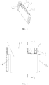
FIG. 1 is a structural schematic diagram of a battery module according to an embodiment of the present disclosure; -
FIG. 2 is an exploded view of a case and an end cap ofFIG. 1 ; -
FIG. 3 is a structural schematic diagram of the end cap ofFIG. 1 ; -
FIG. 4 is a right side view ofFIG. 1 ; -
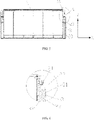
FIG. 5 is a cross-sectional view taken along line A-A inFIG. 4 ; and -
FIG. 6 is an enlarged view of a portion A inFIG. 5 . -
- 1 - case body;
- 11 - side plate;
- 12 - end plate;
- 2 - output electrode assembly;
- 21 - output electrode body;
- 22 - electrode insulator;
- 23 - connecting portion;
- 3 - end cap;
- 31 - first groove;
- 32 - second groove;
- 33 - through-hole;
- 4 - locating piece;
- 41- connecting arm;
- 42 - fixed arm.
- The embodiments of the present disclosure will be clearly, comprehensively described in combination with the drawings. The embodiments described below are merely a part of the embodiments of the present disclosure. Based on these embodiments described in the present disclosure, other embodiments obtained by those skilled in the art without any creative efforts shall fall within the protection scope of the present disclosure.
- It should be understood that terms indicating orientations or positions, such as "inside", "outside", etc., generally are used to describe the orientations or positions with reference to the drawings. These terms are merely intended to facilitate and simplify the description of the present disclosure, rather than indicate or imply that a device or element is disposed at a fixed position or is operated in a fixed orientation or configuration. That is, these terms should not be construed as limitations of the present disclosure.
- It should be noted that terms used in the present disclosure such as "mounted", "assembled", and "connected", etc. shall be understood in a broad extent, unless otherwise specified or limited. For example, the term "connected" includes various connection manners, such as fixed connection, detachable connection, integrated connection; mechanical connection, electrical connection; direct connection, indirect connection via an intermediate medium, or internal connection of two elements. These skilled in the art are able to understand specific meanings of the above terms in accordance with specific circumstances.
- As shown in
FIG. 1, FIG. 2 ,FIG. 4 ,FIG. 5 and FIG. 6 , the present embodiment provides a battery module. The battery module includes a case body 1, a plurality of battery units accommodated in the cavity of the case body 1, anoutput electrode assembly 2 disposed on the case body 1, and anend cap 3 connected to the case body 1. Theoutput electrode assembly 2 is electrically connected to output terminals of the battery units to ensure normal voltage output of the battery units, and theend cap 3 is arranged to press and cover a part of theoutput electrode assembly 2. When the battery module vibrates during the travelling of the vehicle and theoutput electrode assembly 2 is pulled by a metal connecting member due to the vibration of the battery module, as a part of theoutput electrode assembly 2 is pressed and covered by theend cap 3, the force applied by the metal connecting member is dispersed to theend cap 3. In the meantime, theend cap 3 being tightly pressed against the surface of theoutput electrode assembly 2 can further prevent the airtightness of theoutput electrode assembly 2 from being broken by intensive swaying of the metal connecting member. - The
end cap 3 is connected to the case body 1 by bonding, snap-in, or the like. In order to improve the connection strength between theend cap 3 and the case body 1, theend cap 3 is preferably fixed to the case body 1 by bolts in the present embodiment. - As shown in
FIG. 2 ,FIG. 3 ,FIG. 5 and FIG. 6 , theend cap 3 can be directly pressed against the surface of theoutput electrode assembly 2 to prevent the metal connecting member from pulling theoutput electrode assembly 2. Theoutput electrode assembly 2 may include anoutput electrode body 21 electrically connected to the output terminals of the battery units, and anelectrode insulator 22 disposed on the case body 1. Theelectrode insulator 22 wraps theoutput electrode body 21. A surface of theend cap 3 to be matched with theelectrode insulator 22 is recessed to form afirst groove 31, and thefirst groove 31 is used for accommodating theelectrode insulator 22. By placing theoutput electrode body 21 in thefirst groove 31, the stability of the connection between theend cap 3 and theoutput electrode body 21 is improved. At the same time, the contact area between theoutput electrode body 21 and theend cap 3 is enlarged, such that theend cap 3 is tightly pressed against the surface of theoutput electrode assembly 2, thereby preventing the airtightness of theoutput electrode assembly 2 from being broken by the intensive swaying of the metal connecting member. - As shown in
FIG. 2 ,FIG. 3 ,FIG. 5 and FIG. 6 , when the battery module vibrates, the metal connecting member pulls theoutput electrode assembly 2 mainly in a direction towards theend cap 3, that is, along an X-axis direction (a connecting direction of the two end plates 12). Since theelectrode insulator 22 is disposed in thefirst groove 31 of theend cap 3, theend cap 3 applies a force in a direction opposite to the X-axis direction (the connecting direction of the two end plates 12) to the electrode output member, thereby decomposing the force of the metal connecting member applying on theelectrode insulator 22. In this way, the airtightness of theoutput electrode assembly 2 is prevented from being broken by the intensive swaying of the metal connecting member. - As shown in
FIG. 5 and FIG. 6 , theelectrode insulator 22 can be partially or integrally disposed in thefirst groove 31. In the embodiment, the depth of thefirst groove 31 can be reduced as much as possible, so as to ensure the strength of theend cap 3 itself, while theend cap 3 can be tightly pressed against the surface of theelectrode insulator 22. Preferably, thefirst groove 31 is in contact with a part of theelectrode insulator 22, and thefirst groove 31 is a non-through groove. - In order to achieve a good insulation effect of the
electrode insulator 22, theelectrode insulator 22 can be made of one or more of polyethylene, polypropylene or polyimide, and theelectrode insulator 22 wraps theoutput electrode body 21 by injection molding with rubber. - In addition, the
electrode insulator 22 may also be not in contact with a side wall of thefirst groove 31. In order to ensure that theend cap 3 can be tightly pressed against the electrode insulator 22a while reducing a pulling force applied on theelectrode insulator 22 by the metal connecting member in any direction, the part of theelectrode insulator 22 contacting thefirst groove 31 is in contact with the side wall of thefirst groove 31. - Further referring to
FIG. 5 and FIG. 6 , theoutput electrode assembly 2 further includes a connectingportion 23 connected to theelectrode insulator 22. A bottom of thefirst groove 31 is recessed to form asecond groove 32. Thesecond groove 32 fits and limits the connectingportion 23, and the connectingportion 23 is in contact with a side wall of thesecond groove 32. With such structure, the stability of the connection between theend cap 3 and theoutput electrode body 21 can be improved, and the contact area between theoutput electrode body 21 and theend cap 3 is enlarged at the same time, thereby preventing the airtightness of theoutput electrode assembly 2 from being broken by the intensive swaying of the metal connecting member. - The part of the
electrode insulator 22 contacting thefirst groove 31 is in contact with the side wall of thefirst groove 31, and the connectingportion 23 is in contact with the side wall of thesecond groove 32. The contact can be a partial contact or complete contact, which is not specified in the present disclosure. - The connecting
portion 23 and theelectrode insulator 22 can be connected together by bonding, snap-in or screwing, etc., in order to improve the connection strength between the connectingportion 23 and theelectrode insulator 22. For example, the connectingportion 23 and theelectrode insulator 22 may be formed into one piece. - As shown in
FIG. 2 , in order to improve the firmness and stability of the connection between the connectingportion 23 and thesecond groove 32, in the present embodiment, the connectingportion 23 may be a flared protrusion structure. - As shown in
FIG. 1 and FIG. 2 , the case body 1 includes twoside plates 11 and twoend plates 12, and the twoside plates 11 and the twoend plates 12 are connected, head to tail, to enclose the cavity of the case body. Theoutput electrode assembly 2 is arranged on any oneend plate 12. In order to firmly and easily connect theend cap 3 to the case body 1, a locating piece 4 is provided on an end of theside plate 11 close to theend cap 3, and the locating piece 4 fits and limits theend cap 3. - The locating piece 4 includes a connecting
arm 41 connected to theside plate 11, and a fixedarm 42 connected to the connectingarm 41. A non-zero angle is enclosed by the connectingarm 41 and the fixedarm 42. Theend cap 3 is clamped between the fixedarms 42 corresponding todifferent side plates 11. With such structure, the clamping force of the two fixedarm 42 can primarily connect theend cap 3 to the case body 1, which facilitates the further fixing of theend cap 3, and can further improve the stability of the connection between theend cap 3 and the case body 1. - The connecting
arm 41 and theside plate 11 can be connected together by bonding, or snap-in, etc., and the fixedarm 42 and the connectingarm 41 can be connected together by bonding, or snap-in, etc. In order to improve the connection strength between the connectingarm 41 and theend plate 12 and the connection strength between the fixedarm 42 and connectingarm 41, the connectingarm 41 and theend plate 12 may be formed into one piece, and the fixedarm 42 and the connectingarm 41 may be formed into one piece. - The fixed
arm 42 can be connected to the connectingarm 41 via a sharp corner transition. In the present embodiment, for example, the fixedarm 41 may be connected to the connectingarm 41 via an arc transition. By connecting the connectingarm 41 and the fixedarm 42 with the arc transition, a stress at the connection between the fixedarm 42 and the connectingarm 41 can be uniformly distributed along a normal of the arc. In this way, a product failure, which is caused by the occurrence of cracks at the connection structure, can be reduced or even avoided, thereby further increasing the clamping force of the fixedarm 42 against theend cap 3. - As shown in
FIG. 2 , a surface of theend cap 3 to be matched with the fixedarm 42 can be a flat surface. In order to increase the contact area between theend cap 3 and the fixedarm 42 and enhance the stability of theend cap 3, the surface of theend cap 3 to be matched with the fixedarm 42 can be an arc surface. - As shown in
FIG. 5 , in the present embodiment, theend cap 3 is provided with multiple through-holes 33 to reduce a weight of theend plate 12. The through-holes 33 are provided along the X axis direction (the connection direction of the two end plates 12). In order to further reduce the weight of the end plate and ensure the structural strength of theend plate 12, the through-holes 33 may be also provided along the Y axis direction (a direction perpendicular to the connection direction of the two end plates 12) at the same time.
Claims (8)
- A battery module, comprising:a case body (1) having a cavity;a plurality of battery units accommodated in the cavity of the case body (1);an output electrode assembly (2) disposed on the case body (1) and electrically connected to output terminals of the plurality of battery units; andan end cap (3) connected to the case body (1), wherein the end cap (3) presses and covers at least a part of the output electrode assembly (2),wherein the output electrode assembly (2) comprises:an output electrode body (21) electrically connected to the output terminals of the plurality of battery units; andan electrode insulator (22) disposed on the case body (1), wherein the electrode insulator (22) wraps the output electrode body (21),wherein a surface of the end cap (3) to be matched with the electrode insulator (22) is recessed to form a first groove (31), and the first groove (31) is configured to accommodate the electrode insulator (22),characterized in that the output electrode assembly (2) further comprises a connecting portion (23) connected to the electrode insulator (22), andwherein a bottom of the first groove (31) is recessed to form a second groove (32), the second groove (32) fits and limits the connecting portion (23), and the connecting portion (23) is in contact with a side wall of the second groove (32).
- The battery module according to claim 1, characterized in that a part of the electrode insulator (22) contacting the first groove (31) is in contact with a side wall of the first groove (31).
- The battery module according to claim 1, characterized in that the connecting portion (23) is a flared protrusion structure.
- The battery module according to claim 1, characterized in that the case body (1) comprises:two side plates (11); andtwo end plates (12),wherein the cavity of the case body (1) is enclosed by the two side plates (11) and the two end plates (12), and the output electrode assembly (2) is arranged on any one of the two end plates (12), andwherein a locating piece (4) is provided on an end of each of the two side plates (11) close to the end cap (3), and the locating piece (4) fits and limits the end cap (3).
- The battery module according to claim 4, characterized in that the locating piece (4) comprises:a connecting arm (41) connected to each of the two side plates (11); anda fixed arm (42) connected to the connecting arm (41) in a non-zero angle with respect to the connecting arm (41),wherein the end cap (3) is clamped by the fixed arms (42) corresponding to the two side plates (11).
- The battery module according to claim 5, characterized in that the fixed arm (42) is connected to the connecting arm (41) via an arc transition.
- The battery module according to claim 6, characterized in that a surface of the end cap (3) to be matched with the fixed arm (42) is an arc surface.
- The battery module according to claim 1, characterized in that the end cap (3) is provided with a plurality of through-holes (33).
Applications Claiming Priority (1)
| Application Number | Priority Date | Filing Date | Title |
|---|---|---|---|
| CN201821570726.9U CN208674174U (en) | 2018-09-26 | 2018-09-26 | battery module |
Publications (2)
| Publication Number | Publication Date |
|---|---|
| EP3629398A1 EP3629398A1 (en) | 2020-04-01 |
| EP3629398B1 true EP3629398B1 (en) | 2022-05-04 |
Family
ID=65842923
Family Applications (1)
| Application Number | Title | Priority Date | Filing Date |
|---|---|---|---|
| EP19179315.7A Active EP3629398B1 (en) | 2018-09-26 | 2019-06-11 | Battery module |
Country Status (3)
| Country | Link |
|---|---|
| US (1) | US11189857B2 (en) |
| EP (1) | EP3629398B1 (en) |
| CN (1) | CN208674174U (en) |
Families Citing this family (3)
| Publication number | Priority date | Publication date | Assignee | Title |
|---|---|---|---|---|
| CN111834560B (en) * | 2019-04-15 | 2021-12-07 | 宁德时代新能源科技股份有限公司 | Battery module |
| CN209496933U (en) * | 2019-04-19 | 2019-10-15 | 宁德时代新能源科技股份有限公司 | battery pack |
| CN214378714U (en) * | 2021-04-01 | 2021-10-08 | 北京车和家信息技术有限公司 | Protection component and battery module |
Family Cites Families (9)
| Publication number | Priority date | Publication date | Assignee | Title |
|---|---|---|---|---|
| US7320843B2 (en) * | 2004-02-27 | 2008-01-22 | Great Stuff, Inc. | Battery assembly with shielded terminals |
| EP2279539A1 (en) * | 2008-05-15 | 2011-02-02 | Johnson Controls Saft Advanced Power Solutions LLC | Battery system |
| KR101082862B1 (en) * | 2008-10-14 | 2011-11-11 | 주식회사 엘지화학 | Battery Pack Containing Electrode Terminal Connecting Device |
| KR101146363B1 (en) * | 2010-06-04 | 2012-05-17 | 에스비리모티브 주식회사 | Battery pack |
| KR101443833B1 (en) * | 2012-03-26 | 2014-09-23 | 주식회사 엘지화학 | External Input and Output Cable Assembly with Novel Structure, and Battery Module Assembly Employed with the Same |
| KR101689750B1 (en) * | 2014-01-21 | 2016-12-26 | 주식회사 엘지화학 | Battery pack |
| US9620761B2 (en) * | 2014-09-09 | 2017-04-11 | Lg Chem, Ltd. | Battery cell interconnect and voltage sensing assembly and a battery module |
| JP5852201B1 (en) * | 2014-09-18 | 2016-02-03 | 日本電気株式会社 | Electric shock protection structure and method |
| CN108352473B (en) * | 2015-11-04 | 2021-01-29 | 株式会社村田制作所 | Power storage device, assembly, method of assembling power storage device, and electric/electronic apparatus |
-
2018
- 2018-09-26 CN CN201821570726.9U patent/CN208674174U/en active Active
-
2019
- 2019-06-11 EP EP19179315.7A patent/EP3629398B1/en active Active
- 2019-08-23 US US16/549,558 patent/US11189857B2/en active Active
Also Published As
| Publication number | Publication date |
|---|---|
| CN208674174U (en) | 2019-03-29 |
| US11189857B2 (en) | 2021-11-30 |
| US20200099025A1 (en) | 2020-03-26 |
| EP3629398A1 (en) | 2020-04-01 |
Similar Documents
| Publication | Publication Date | Title |
|---|---|---|
| CN109792010B (en) | Assembled battery | |
| CN106876621B (en) | Rechargeable Battery Module | |
| KR102344362B1 (en) | Battery Module | |
| KR101146363B1 (en) | Battery pack | |
| EP2736097B1 (en) | Rechargeable battery and module of the same | |
| US9034514B2 (en) | Electric storage device | |
| EP3629398B1 (en) | Battery module | |
| JP2005322647A (en) | Secondary battery module | |
| EP2797138B1 (en) | Battery pack | |
| US20120156548A1 (en) | Secondary Battery and Battery Pack Including the Same | |
| KR20100065669A (en) | Rechargeable battery and battery module using thereof | |
| KR20140094207A (en) | Rechargeable battery module | |
| JP2012113944A (en) | Battery module | |
| EP2538468B1 (en) | Terminal for module | |
| CN115347294A (en) | Battery pack | |
| CN210744052U (en) | Battery packs and devices | |
| JP5786794B2 (en) | battery | |
| CN219144298U (en) | Top cover of power battery | |
| KR101574083B1 (en) | Rechargeable battery | |
| CN118040200A (en) | Battery and electricity utilization device | |
| WO2024140426A1 (en) | Battery pack and external device | |
| KR20250036882A (en) | Battery cells, batteries and electrical devices | |
| CN222355298U (en) | Battery system | |
| CN219739254U (en) | Battery and battery device | |
| KR20210060239A (en) | Battery module, battery pack and vehicle comprising the same |
Legal Events
| Date | Code | Title | Description |
|---|---|---|---|
| STAA | Information on the status of an ep patent application or granted ep patent |
Free format text: STATUS: EXAMINATION IS IN PROGRESS |
|
| PUAI | Public reference made under article 153(3) epc to a published international application that has entered the european phase |
Free format text: ORIGINAL CODE: 0009012 |
|
| 17P | Request for examination filed |
Effective date: 20190611 |
|
| AK | Designated contracting states |
Kind code of ref document: A1 Designated state(s): AL AT BE BG CH CY CZ DE DK EE ES FI FR GB GR HR HU IE IS IT LI LT LU LV MC MK MT NL NO PL PT RO RS SE SI SK SM TR |
|
| AX | Request for extension of the european patent |
Extension state: BA ME |
|
| REG | Reference to a national code |
Ref country code: DE Ref legal event code: R079 Ref document number: 602019014352 Country of ref document: DE Free format text: PREVIOUS MAIN CLASS: H01M0002100000 Ipc: H01M0010420000 |
|
| GRAP | Despatch of communication of intention to grant a patent |
Free format text: ORIGINAL CODE: EPIDOSNIGR1 |
|
| STAA | Information on the status of an ep patent application or granted ep patent |
Free format text: STATUS: GRANT OF PATENT IS INTENDED |
|
| RIC1 | Information provided on ipc code assigned before grant |
Ipc: H01M 50/543 20210101ALI20220124BHEP Ipc: H01M 50/20 20210101ALI20220124BHEP Ipc: H01M 10/42 20060101AFI20220124BHEP |
|
| GRAS | Grant fee paid |
Free format text: ORIGINAL CODE: EPIDOSNIGR3 |
|
| INTG | Intention to grant announced |
Effective date: 20220301 |
|
| GRAA | (expected) grant |
Free format text: ORIGINAL CODE: 0009210 |
|
| STAA | Information on the status of an ep patent application or granted ep patent |
Free format text: STATUS: THE PATENT HAS BEEN GRANTED |
|
| AK | Designated contracting states |
Kind code of ref document: B1 Designated state(s): AL AT BE BG CH CY CZ DE DK EE ES FI FR GB GR HR HU IE IS IT LI LT LU LV MC MK MT NL NO PL PT RO RS SE SI SK SM TR |
|
| REG | Reference to a national code |
Ref country code: GB Ref legal event code: FG4D |
|
| REG | Reference to a national code |
Ref country code: CH Ref legal event code: EP |
|
| REG | Reference to a national code |
Ref country code: AT Ref legal event code: REF Ref document number: 1490097 Country of ref document: AT Kind code of ref document: T Effective date: 20220515 |
|
| REG | Reference to a national code |
Ref country code: DE Ref legal event code: R096 Ref document number: 602019014352 Country of ref document: DE |
|
| REG | Reference to a national code |
Ref country code: IE Ref legal event code: FG4D |
|
| REG | Reference to a national code |
Ref country code: LT Ref legal event code: MG9D |
|
| REG | Reference to a national code |
Ref country code: NL Ref legal event code: MP Effective date: 20220504 |
|
| REG | Reference to a national code |
Ref country code: AT Ref legal event code: MK05 Ref document number: 1490097 Country of ref document: AT Kind code of ref document: T Effective date: 20220504 |
|
| PG25 | Lapsed in a contracting state [announced via postgrant information from national office to epo] |
Ref country code: SE Free format text: LAPSE BECAUSE OF FAILURE TO SUBMIT A TRANSLATION OF THE DESCRIPTION OR TO PAY THE FEE WITHIN THE PRESCRIBED TIME-LIMIT Effective date: 20220504 Ref country code: PT Free format text: LAPSE BECAUSE OF FAILURE TO SUBMIT A TRANSLATION OF THE DESCRIPTION OR TO PAY THE FEE WITHIN THE PRESCRIBED TIME-LIMIT Effective date: 20220905 Ref country code: NO Free format text: LAPSE BECAUSE OF FAILURE TO SUBMIT A TRANSLATION OF THE DESCRIPTION OR TO PAY THE FEE WITHIN THE PRESCRIBED TIME-LIMIT Effective date: 20220804 Ref country code: NL Free format text: LAPSE BECAUSE OF FAILURE TO SUBMIT A TRANSLATION OF THE DESCRIPTION OR TO PAY THE FEE WITHIN THE PRESCRIBED TIME-LIMIT Effective date: 20220504 Ref country code: LT Free format text: LAPSE BECAUSE OF FAILURE TO SUBMIT A TRANSLATION OF THE DESCRIPTION OR TO PAY THE FEE WITHIN THE PRESCRIBED TIME-LIMIT Effective date: 20220504 Ref country code: HR Free format text: LAPSE BECAUSE OF FAILURE TO SUBMIT A TRANSLATION OF THE DESCRIPTION OR TO PAY THE FEE WITHIN THE PRESCRIBED TIME-LIMIT Effective date: 20220504 Ref country code: GR Free format text: LAPSE BECAUSE OF FAILURE TO SUBMIT A TRANSLATION OF THE DESCRIPTION OR TO PAY THE FEE WITHIN THE PRESCRIBED TIME-LIMIT Effective date: 20220805 Ref country code: FI Free format text: LAPSE BECAUSE OF FAILURE TO SUBMIT A TRANSLATION OF THE DESCRIPTION OR TO PAY THE FEE WITHIN THE PRESCRIBED TIME-LIMIT Effective date: 20220504 Ref country code: ES Free format text: LAPSE BECAUSE OF FAILURE TO SUBMIT A TRANSLATION OF THE DESCRIPTION OR TO PAY THE FEE WITHIN THE PRESCRIBED TIME-LIMIT Effective date: 20220504 Ref country code: BG Free format text: LAPSE BECAUSE OF FAILURE TO SUBMIT A TRANSLATION OF THE DESCRIPTION OR TO PAY THE FEE WITHIN THE PRESCRIBED TIME-LIMIT Effective date: 20220804 Ref country code: AT Free format text: LAPSE BECAUSE OF FAILURE TO SUBMIT A TRANSLATION OF THE DESCRIPTION OR TO PAY THE FEE WITHIN THE PRESCRIBED TIME-LIMIT Effective date: 20220504 |
|
| PG25 | Lapsed in a contracting state [announced via postgrant information from national office to epo] |
Ref country code: RS Free format text: LAPSE BECAUSE OF FAILURE TO SUBMIT A TRANSLATION OF THE DESCRIPTION OR TO PAY THE FEE WITHIN THE PRESCRIBED TIME-LIMIT Effective date: 20220504 Ref country code: PL Free format text: LAPSE BECAUSE OF FAILURE TO SUBMIT A TRANSLATION OF THE DESCRIPTION OR TO PAY THE FEE WITHIN THE PRESCRIBED TIME-LIMIT Effective date: 20220504 Ref country code: LV Free format text: LAPSE BECAUSE OF FAILURE TO SUBMIT A TRANSLATION OF THE DESCRIPTION OR TO PAY THE FEE WITHIN THE PRESCRIBED TIME-LIMIT Effective date: 20220504 Ref country code: IS Free format text: LAPSE BECAUSE OF FAILURE TO SUBMIT A TRANSLATION OF THE DESCRIPTION OR TO PAY THE FEE WITHIN THE PRESCRIBED TIME-LIMIT Effective date: 20220904 |
|
| PG25 | Lapsed in a contracting state [announced via postgrant information from national office to epo] |
Ref country code: SM Free format text: LAPSE BECAUSE OF FAILURE TO SUBMIT A TRANSLATION OF THE DESCRIPTION OR TO PAY THE FEE WITHIN THE PRESCRIBED TIME-LIMIT Effective date: 20220504 Ref country code: SK Free format text: LAPSE BECAUSE OF FAILURE TO SUBMIT A TRANSLATION OF THE DESCRIPTION OR TO PAY THE FEE WITHIN THE PRESCRIBED TIME-LIMIT Effective date: 20220504 Ref country code: RO Free format text: LAPSE BECAUSE OF FAILURE TO SUBMIT A TRANSLATION OF THE DESCRIPTION OR TO PAY THE FEE WITHIN THE PRESCRIBED TIME-LIMIT Effective date: 20220504 Ref country code: EE Free format text: LAPSE BECAUSE OF FAILURE TO SUBMIT A TRANSLATION OF THE DESCRIPTION OR TO PAY THE FEE WITHIN THE PRESCRIBED TIME-LIMIT Effective date: 20220504 Ref country code: DK Free format text: LAPSE BECAUSE OF FAILURE TO SUBMIT A TRANSLATION OF THE DESCRIPTION OR TO PAY THE FEE WITHIN THE PRESCRIBED TIME-LIMIT Effective date: 20220504 Ref country code: CZ Free format text: LAPSE BECAUSE OF FAILURE TO SUBMIT A TRANSLATION OF THE DESCRIPTION OR TO PAY THE FEE WITHIN THE PRESCRIBED TIME-LIMIT Effective date: 20220504 |
|
| REG | Reference to a national code |
Ref country code: CH Ref legal event code: PL |
|
| REG | Reference to a national code |
Ref country code: DE Ref legal event code: R097 Ref document number: 602019014352 Country of ref document: DE |
|
| PG25 | Lapsed in a contracting state [announced via postgrant information from national office to epo] |
Ref country code: MC Free format text: LAPSE BECAUSE OF FAILURE TO SUBMIT A TRANSLATION OF THE DESCRIPTION OR TO PAY THE FEE WITHIN THE PRESCRIBED TIME-LIMIT Effective date: 20220504 |
|
| PLBE | No opposition filed within time limit |
Free format text: ORIGINAL CODE: 0009261 |
|
| STAA | Information on the status of an ep patent application or granted ep patent |
Free format text: STATUS: NO OPPOSITION FILED WITHIN TIME LIMIT |
|
| PG25 | Lapsed in a contracting state [announced via postgrant information from national office to epo] |
Ref country code: AL Free format text: LAPSE BECAUSE OF FAILURE TO SUBMIT A TRANSLATION OF THE DESCRIPTION OR TO PAY THE FEE WITHIN THE PRESCRIBED TIME-LIMIT Effective date: 20220504 |
|
| 26N | No opposition filed |
Effective date: 20230207 |
|
| PG25 | Lapsed in a contracting state [announced via postgrant information from national office to epo] |
Ref country code: LU Free format text: LAPSE BECAUSE OF NON-PAYMENT OF DUE FEES Effective date: 20220611 Ref country code: LI Free format text: LAPSE BECAUSE OF NON-PAYMENT OF DUE FEES Effective date: 20220630 Ref country code: IE Free format text: LAPSE BECAUSE OF NON-PAYMENT OF DUE FEES Effective date: 20220611 Ref country code: CH Free format text: LAPSE BECAUSE OF NON-PAYMENT OF DUE FEES Effective date: 20220630 |
|
| PG25 | Lapsed in a contracting state [announced via postgrant information from national office to epo] |
Ref country code: SI Free format text: LAPSE BECAUSE OF FAILURE TO SUBMIT A TRANSLATION OF THE DESCRIPTION OR TO PAY THE FEE WITHIN THE PRESCRIBED TIME-LIMIT Effective date: 20220504 |
|
| P01 | Opt-out of the competence of the unified patent court (upc) registered |
Effective date: 20230516 |
|
| PG25 | Lapsed in a contracting state [announced via postgrant information from national office to epo] |
Ref country code: IT Free format text: LAPSE BECAUSE OF FAILURE TO SUBMIT A TRANSLATION OF THE DESCRIPTION OR TO PAY THE FEE WITHIN THE PRESCRIBED TIME-LIMIT Effective date: 20220504 |
|
| PG25 | Lapsed in a contracting state [announced via postgrant information from national office to epo] |
Ref country code: MK Free format text: LAPSE BECAUSE OF FAILURE TO SUBMIT A TRANSLATION OF THE DESCRIPTION OR TO PAY THE FEE WITHIN THE PRESCRIBED TIME-LIMIT Effective date: 20220504 Ref country code: CY Free format text: LAPSE BECAUSE OF FAILURE TO SUBMIT A TRANSLATION OF THE DESCRIPTION OR TO PAY THE FEE WITHIN THE PRESCRIBED TIME-LIMIT Effective date: 20220504 |
|
| PG25 | Lapsed in a contracting state [announced via postgrant information from national office to epo] |
Ref country code: HU Free format text: LAPSE BECAUSE OF FAILURE TO SUBMIT A TRANSLATION OF THE DESCRIPTION OR TO PAY THE FEE WITHIN THE PRESCRIBED TIME-LIMIT; INVALID AB INITIO Effective date: 20190611 |
|
| REG | Reference to a national code |
Ref country code: DE Ref legal event code: R081 Ref document number: 602019014352 Country of ref document: DE Owner name: CONTEMPORARY AMPEREX TECHNOLOGY (HONG KONG) LI, HK Free format text: FORMER OWNER: CONTEMPORARY AMPEREX TECHNOLOGY CO., LTD., NINGDE, FUJIAN, CN |
|
| REG | Reference to a national code |
Ref country code: GB Ref legal event code: 732E Free format text: REGISTERED BETWEEN 20240822 AND 20240828 |
|
| PG25 | Lapsed in a contracting state [announced via postgrant information from national office to epo] |
Ref country code: MT Free format text: LAPSE BECAUSE OF FAILURE TO SUBMIT A TRANSLATION OF THE DESCRIPTION OR TO PAY THE FEE WITHIN THE PRESCRIBED TIME-LIMIT Effective date: 20220504 |
|
| PG25 | Lapsed in a contracting state [announced via postgrant information from national office to epo] |
Ref country code: BG Free format text: LAPSE BECAUSE OF FAILURE TO SUBMIT A TRANSLATION OF THE DESCRIPTION OR TO PAY THE FEE WITHIN THE PRESCRIBED TIME-LIMIT Effective date: 20220504 |
|
| PG25 | Lapsed in a contracting state [announced via postgrant information from national office to epo] |
Ref country code: BG Free format text: LAPSE BECAUSE OF FAILURE TO SUBMIT A TRANSLATION OF THE DESCRIPTION OR TO PAY THE FEE WITHIN THE PRESCRIBED TIME-LIMIT Effective date: 20220504 |
|
| REG | Reference to a national code |
Ref country code: BE Ref legal event code: PD Owner name: CONTEMPORARY AMPEREX TECHNOLOGY (HONG KONG) LIMITED; CN Free format text: DETAILS ASSIGNMENT: CHANGE OF OWNER(S), ASSIGNMENT; FORMER OWNER NAME: CONTEMPORARY AMPEREX TECHNOLOGY CO., LIMITED Effective date: 20240807 |
|
| PGFP | Annual fee paid to national office [announced via postgrant information from national office to epo] |
Ref country code: DE Payment date: 20250402 Year of fee payment: 7 |
|
| PGFP | Annual fee paid to national office [announced via postgrant information from national office to epo] |
Ref country code: GB Payment date: 20250401 Year of fee payment: 7 |
|
| PGFP | Annual fee paid to national office [announced via postgrant information from national office to epo] |
Ref country code: BE Payment date: 20250410 Year of fee payment: 7 |
|
| PGFP | Annual fee paid to national office [announced via postgrant information from national office to epo] |
Ref country code: FR Payment date: 20250401 Year of fee payment: 7 |
|
| PG25 | Lapsed in a contracting state [announced via postgrant information from national office to epo] |
Ref country code: TR Free format text: LAPSE BECAUSE OF FAILURE TO SUBMIT A TRANSLATION OF THE DESCRIPTION OR TO PAY THE FEE WITHIN THE PRESCRIBED TIME-LIMIT Effective date: 20220504 |