EP3629231A1 - Object detection system of a vehicle - Google Patents
Object detection system of a vehicle Download PDFInfo
- Publication number
- EP3629231A1 EP3629231A1 EP19193779.6A EP19193779A EP3629231A1 EP 3629231 A1 EP3629231 A1 EP 3629231A1 EP 19193779 A EP19193779 A EP 19193779A EP 3629231 A1 EP3629231 A1 EP 3629231A1
- Authority
- EP
- European Patent Office
- Prior art keywords
- layers
- image
- image signal
- detection system
- color
- Prior art date
- Legal status (The legal status is an assumption and is not a legal conclusion. Google has not performed a legal analysis and makes no representation as to the accuracy of the status listed.)
- Granted
Links
Images




Classifications
-
- G—PHYSICS
- G06—COMPUTING OR CALCULATING; COUNTING
- G06V—IMAGE OR VIDEO RECOGNITION OR UNDERSTANDING
- G06V20/00—Scenes; Scene-specific elements
- G06V20/50—Context or environment of the image
- G06V20/56—Context or environment of the image exterior to a vehicle by using sensors mounted on the vehicle
- G06V20/58—Recognition of moving objects or obstacles, e.g. vehicles or pedestrians; Recognition of traffic objects, e.g. traffic signs, traffic lights or roads
-
- G—PHYSICS
- G06—COMPUTING OR CALCULATING; COUNTING
- G06F—ELECTRIC DIGITAL DATA PROCESSING
- G06F18/00—Pattern recognition
- G06F18/20—Analysing
- G06F18/24—Classification techniques
-
- G—PHYSICS
- G06—COMPUTING OR CALCULATING; COUNTING
- G06F—ELECTRIC DIGITAL DATA PROCESSING
- G06F18/00—Pattern recognition
- G06F18/20—Analysing
- G06F18/24—Classification techniques
- G06F18/241—Classification techniques relating to the classification model, e.g. parametric or non-parametric approaches
-
- G—PHYSICS
- G06—COMPUTING OR CALCULATING; COUNTING
- G06F—ELECTRIC DIGITAL DATA PROCESSING
- G06F18/00—Pattern recognition
- G06F18/20—Analysing
- G06F18/25—Fusion techniques
- G06F18/253—Fusion techniques of extracted features
-
- G—PHYSICS
- G06—COMPUTING OR CALCULATING; COUNTING
- G06F—ELECTRIC DIGITAL DATA PROCESSING
- G06F18/00—Pattern recognition
- G06F18/20—Analysing
- G06F18/25—Fusion techniques
- G06F18/254—Fusion techniques of classification results, e.g. of results related to same input data
- G06F18/256—Fusion techniques of classification results, e.g. of results related to same input data of results relating to different input data, e.g. multimodal recognition
-
- G—PHYSICS
- G06—COMPUTING OR CALCULATING; COUNTING
- G06T—IMAGE DATA PROCESSING OR GENERATION, IN GENERAL
- G06T7/00—Image analysis
- G06T7/50—Depth or shape recovery
- G06T7/521—Depth or shape recovery from laser ranging, e.g. using interferometry; from the projection of structured light
-
- G—PHYSICS
- G06—COMPUTING OR CALCULATING; COUNTING
- G06T—IMAGE DATA PROCESSING OR GENERATION, IN GENERAL
- G06T7/00—Image analysis
- G06T7/70—Determining position or orientation of objects or cameras
- G06T7/73—Determining position or orientation of objects or cameras using feature-based methods
-
- G—PHYSICS
- G06—COMPUTING OR CALCULATING; COUNTING
- G06V—IMAGE OR VIDEO RECOGNITION OR UNDERSTANDING
- G06V10/00—Arrangements for image or video recognition or understanding
- G06V10/40—Extraction of image or video features
- G06V10/44—Local feature extraction by analysis of parts of the pattern, e.g. by detecting edges, contours, loops, corners, strokes or intersections; Connectivity analysis, e.g. of connected components
- G06V10/443—Local feature extraction by analysis of parts of the pattern, e.g. by detecting edges, contours, loops, corners, strokes or intersections; Connectivity analysis, e.g. of connected components by matching or filtering
- G06V10/449—Biologically inspired filters, e.g. difference of Gaussians [DoG] or Gabor filters
- G06V10/451—Biologically inspired filters, e.g. difference of Gaussians [DoG] or Gabor filters with interaction between the filter responses, e.g. cortical complex cells
- G06V10/454—Integrating the filters into a hierarchical structure, e.g. convolutional neural networks [CNN]
-
- G—PHYSICS
- G06—COMPUTING OR CALCULATING; COUNTING
- G06V—IMAGE OR VIDEO RECOGNITION OR UNDERSTANDING
- G06V10/00—Arrangements for image or video recognition or understanding
- G06V10/70—Arrangements for image or video recognition or understanding using pattern recognition or machine learning
- G06V10/77—Processing image or video features in feature spaces; using data integration or data reduction, e.g. principal component analysis [PCA] or independent component analysis [ICA] or self-organising maps [SOM]; Blind source separation
- G06V10/80—Fusion, i.e. combining data from various sources at the sensor level, preprocessing level, feature extraction level or classification level
- G06V10/806—Fusion, i.e. combining data from various sources at the sensor level, preprocessing level, feature extraction level or classification level of extracted features
-
- G—PHYSICS
- G06—COMPUTING OR CALCULATING; COUNTING
- G06V—IMAGE OR VIDEO RECOGNITION OR UNDERSTANDING
- G06V10/00—Arrangements for image or video recognition or understanding
- G06V10/70—Arrangements for image or video recognition or understanding using pattern recognition or machine learning
- G06V10/82—Arrangements for image or video recognition or understanding using pattern recognition or machine learning using neural networks
-
- G—PHYSICS
- G06—COMPUTING OR CALCULATING; COUNTING
- G06V—IMAGE OR VIDEO RECOGNITION OR UNDERSTANDING
- G06V40/00—Recognition of biometric, human-related or animal-related patterns in image or video data
- G06V40/10—Human or animal bodies, e.g. vehicle occupants or pedestrians; Body parts, e.g. hands
- G06V40/103—Static body considered as a whole, e.g. static pedestrian or occupant recognition
-
- H—ELECTRICITY
- H04—ELECTRIC COMMUNICATION TECHNIQUE
- H04N—PICTORIAL COMMUNICATION, e.g. TELEVISION
- H04N23/00—Cameras or camera modules comprising electronic image sensors; Control thereof
- H04N23/10—Cameras or camera modules comprising electronic image sensors; Control thereof for generating image signals from different wavelengths
- H04N23/11—Cameras or camera modules comprising electronic image sensors; Control thereof for generating image signals from different wavelengths for generating image signals from visible and infrared light wavelengths
-
- H—ELECTRICITY
- H04—ELECTRIC COMMUNICATION TECHNIQUE
- H04N—PICTORIAL COMMUNICATION, e.g. TELEVISION
- H04N23/00—Cameras or camera modules comprising electronic image sensors; Control thereof
- H04N23/10—Cameras or camera modules comprising electronic image sensors; Control thereof for generating image signals from different wavelengths
- H04N23/13—Cameras or camera modules comprising electronic image sensors; Control thereof for generating image signals from different wavelengths with multiple sensors
-
- G—PHYSICS
- G01—MEASURING; TESTING
- G01S—RADIO DIRECTION-FINDING; RADIO NAVIGATION; DETERMINING DISTANCE OR VELOCITY BY USE OF RADIO WAVES; LOCATING OR PRESENCE-DETECTING BY USE OF THE REFLECTION OR RERADIATION OF RADIO WAVES; ANALOGOUS ARRANGEMENTS USING OTHER WAVES
- G01S13/00—Systems using the reflection or reradiation of radio waves, e.g. radar systems; Analogous systems using reflection or reradiation of waves whose nature or wavelength is irrelevant or unspecified
- G01S13/86—Combinations of radar systems with non-radar systems, e.g. sonar, direction finder
- G01S13/865—Combination of radar systems with lidar systems
-
- G—PHYSICS
- G01—MEASURING; TESTING
- G01S—RADIO DIRECTION-FINDING; RADIO NAVIGATION; DETERMINING DISTANCE OR VELOCITY BY USE OF RADIO WAVES; LOCATING OR PRESENCE-DETECTING BY USE OF THE REFLECTION OR RERADIATION OF RADIO WAVES; ANALOGOUS ARRANGEMENTS USING OTHER WAVES
- G01S13/00—Systems using the reflection or reradiation of radio waves, e.g. radar systems; Analogous systems using reflection or reradiation of waves whose nature or wavelength is irrelevant or unspecified
- G01S13/86—Combinations of radar systems with non-radar systems, e.g. sonar, direction finder
- G01S13/867—Combination of radar systems with cameras
-
- G—PHYSICS
- G01—MEASURING; TESTING
- G01S—RADIO DIRECTION-FINDING; RADIO NAVIGATION; DETERMINING DISTANCE OR VELOCITY BY USE OF RADIO WAVES; LOCATING OR PRESENCE-DETECTING BY USE OF THE REFLECTION OR RERADIATION OF RADIO WAVES; ANALOGOUS ARRANGEMENTS USING OTHER WAVES
- G01S13/00—Systems using the reflection or reradiation of radio waves, e.g. radar systems; Analogous systems using reflection or reradiation of waves whose nature or wavelength is irrelevant or unspecified
- G01S13/88—Radar or analogous systems specially adapted for specific applications
- G01S13/93—Radar or analogous systems specially adapted for specific applications for anti-collision purposes
- G01S13/931—Radar or analogous systems specially adapted for specific applications for anti-collision purposes of land vehicles
-
- G—PHYSICS
- G01—MEASURING; TESTING
- G01S—RADIO DIRECTION-FINDING; RADIO NAVIGATION; DETERMINING DISTANCE OR VELOCITY BY USE OF RADIO WAVES; LOCATING OR PRESENCE-DETECTING BY USE OF THE REFLECTION OR RERADIATION OF RADIO WAVES; ANALOGOUS ARRANGEMENTS USING OTHER WAVES
- G01S17/00—Systems using the reflection or reradiation of electromagnetic waves other than radio waves, e.g. lidar systems
- G01S17/88—Lidar systems specially adapted for specific applications
- G01S17/93—Lidar systems specially adapted for specific applications for anti-collision purposes
- G01S17/931—Lidar systems specially adapted for specific applications for anti-collision purposes of land vehicles
-
- G—PHYSICS
- G05—CONTROLLING; REGULATING
- G05D—SYSTEMS FOR CONTROLLING OR REGULATING NON-ELECTRIC VARIABLES
- G05D1/00—Control of position, course, altitude or attitude of land, water, air or space vehicles, e.g. using automatic pilots
- G05D1/02—Control of position or course in two dimensions
- G05D1/021—Control of position or course in two dimensions specially adapted to land vehicles
- G05D1/0231—Control of position or course in two dimensions specially adapted to land vehicles using optical position detecting means
- G05D1/0242—Control of position or course in two dimensions specially adapted to land vehicles using optical position detecting means using non-visible light signals, e.g. IR or UV signals
-
- G—PHYSICS
- G05—CONTROLLING; REGULATING
- G05D—SYSTEMS FOR CONTROLLING OR REGULATING NON-ELECTRIC VARIABLES
- G05D1/00—Control of position, course, altitude or attitude of land, water, air or space vehicles, e.g. using automatic pilots
- G05D1/02—Control of position or course in two dimensions
- G05D1/021—Control of position or course in two dimensions specially adapted to land vehicles
- G05D1/0231—Control of position or course in two dimensions specially adapted to land vehicles using optical position detecting means
- G05D1/0246—Control of position or course in two dimensions specially adapted to land vehicles using optical position detecting means using a video camera in combination with image processing means
-
- G—PHYSICS
- G06—COMPUTING OR CALCULATING; COUNTING
- G06T—IMAGE DATA PROCESSING OR GENERATION, IN GENERAL
- G06T2207/00—Indexing scheme for image analysis or image enhancement
- G06T2207/20—Special algorithmic details
- G06T2207/20084—Artificial neural networks [ANN]
-
- G—PHYSICS
- G06—COMPUTING OR CALCULATING; COUNTING
- G06T—IMAGE DATA PROCESSING OR GENERATION, IN GENERAL
- G06T2207/00—Indexing scheme for image analysis or image enhancement
- G06T2207/30—Subject of image; Context of image processing
- G06T2207/30236—Traffic on road, railway or crossing
-
- G—PHYSICS
- G06—COMPUTING OR CALCULATING; COUNTING
- G06T—IMAGE DATA PROCESSING OR GENERATION, IN GENERAL
- G06T2207/00—Indexing scheme for image analysis or image enhancement
- G06T2207/30—Subject of image; Context of image processing
- G06T2207/30248—Vehicle exterior or interior
- G06T2207/30252—Vehicle exterior; Vicinity of vehicle
- G06T2207/30261—Obstacle
Definitions
- the present disclosure relates to object detection systems, and more specifically, to a pedestrian detection system and method of operation.
- Pedestrian detection is a task for many applications including, for example, the area of autonomous driving of a vehicle.
- the detection of pedestrians is an important attribute of an autonomous vehicle before the vehicle may be deployed on urban streets.
- More currently, artificial intelligence, has made progress in the study of pedestrian detection.
- further improvements are desirable especially in environments such as weak illumination, far distance, and occlusion of pedestrians.
- An object detection system includes color and infrared cameras, a controller-circuit, and instructions.
- the color and infrared cameras are configured to output respective color image and infrared image signals.
- the controller-circuit is in communication with the cameras, and includes a processor and a storage medium.
- the processor is configured to receive and transform the color image and infrared image signals into classification and location data associated with a detected object.
- the instructions are stored in the at least one storage medium and executed by the at least one processor, and are configured to utilize the color image and infrared image signals to form respective first and second maps.
- the first map has a first plurality of layers
- the second map has a second plurality of layers. Selected layers from each are paired and fused to form a feature pyramid that facilitates formulation of the classification and location data.
- a method of detecting a pedestrian includes a step of receiving from a visual image sensor, a visual image signal indicative of a visual image of an area.
- the next step includes receiving from a thermal image sensor, a thermal image signal indicative of a thermal image of the area.
- the visual image and thermal image signals are then transformed into classification and localization data by a processor executing instructions that applies a gated fusion unit to detect a pedestrian in the area.
- a controller-circuit facilitates detection of an object.
- the controller-circuit includes at least one processor and at least one storage medium.
- the processor is configured to receive a color image signal and a second image signal respectively received from a color camera and an image device.
- the processor executes instructions to transform the color image signal and the second image signal into respective first and second maps.
- the first map has a first plurality of feature layers
- the second map has a second plurality of feature layers.
- the selected feature layers from the first and second maps are paired and fused using gated fusion to at least in part form a feature pyramid that facilitates the transformation of the color image signal and the second image signal into classification data and location data associated with a detected object.
- the storage medium is configured to store the executable instructions retrieved by the at least one processor.
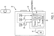
- a system 20 may include a vehicle 22, which may be an autonomous vehicle, and an object detection system 24 (e.g., pedestrian detection system) that may be included as part of the vehicle 22 as illustrated in FIG. 1 .
- vehicle 22 may be any form of transportation for people and/or cargo including marine vehicles, aviation vehicles, and others.
- the vehicle 22 may include at least one controller-circuit 26 and a plurality of sensors or detectors (i.e., three illustrated as 28, 30, 32).
- the controller-circuit 26 includes one or more processors 33, and one or more electronic storage mediums 35.
- the processor 33 is any combination of one or more of a central processing unit (CPU), multiprocessor, microcontroller unit (MCU), digital signal processor (DSP), application specific integrated circuit, and others capable of executing software instructions or otherwise controllable to behave according to predetermined logic.
- the storage medium 35 is, optionally, any combination of read and write memory (RAM) and read only memory (ROM).
- the storage medium 35 may also include persistent storage, which can be any single one, or combination of, solid state memory, magnetic memory, and optical memory storing a computer program (i.e., application) with software instructions.
- the storage medium 35 may be non-transitory.
- the multitude of sensors may include a visual light imaging sensor 28 (i.e., color camera), an infrared or thermal imaging sensor 30 (i.e., long-wavelength infrared sensor), a radar sensor or detector 32, and others.
- the sensors 28, 30, 32 may transmit respective signals (see arrows 34, 36, 38) to the controller-circuit 26, and may each serve multiple functions.
- one or more of the sensors 28, 30, 32 may be part of, or utilized by, various systems of the system 20, or vehicle 22.
- Such systems may include a navigation system (e.g., satellite-based, GPS), a computer vision system, a radar system, a Light Detection and Ranging (LiDAR) system, a land-based system (e.g., beacon stations), and others.
- the infrared sensor 30 may be replaced with a LiDAR sensor.
- the object detection system 24 may be configured to both recognize the presence of an object 39 (e.g., pedestrian) and locate the object with respect to the vehicle 22. In one embodiment, the entire object detection system 24 may be carried by the vehicle 22. In other embodiments, computer instruction aspects and computer processing and/or data storage may be conducted remotely from the vehicle 22 (conducted as part of a remote server function, e.g., cloud).
- a remote server function e.g., cloud
- the object detection system 24 includes at least two of the multitude of sensors 28, 30, 32, computer instructions and/or executable code 40, and data files 42.
- the object detection system 24 includes (or utilizes) the visual light imaging sensor 28 and the thermal imaging sensor 30.
- the object detection system 24 includes the processor 33, or at least utilizes the processor, to execute the computer instruction 40, and includes the storage medium 35, or at least utilizes the storage medium 35, to store the computer instructions 40 and data files 42.
- the signals 34, 36 from the respective sensors 28, 30 are received by the controller-circuit 26, and processed and transformed by the processor 33 utilizing the computer instructions 40 and data file 42 stored in the storage medium 35.
- the processor 33 via the instructions 40 of the object detection system 24, may transform the signals 34, 36 into an object classification 41 and an object location 43 (i.e., classification and location data) as part of the data file 42 (see FIG. 2 ).
- object classification 41 is the classification of each candidate or object into a foreground or background category.
- the object location 43 is the location upon a feature map (to be described below).
- the controller-circuit 26 may then output a signal 44 (e.g., command signal, information signal, and others) to one or more devices 46 that may be external to the controller-circuit 26.
- a signal 44 e.g., command signal, information signal, and others
- devices 46 may include an information display screen for viewing by an occupant of the vehicle 22, a steering device, a braking device, an acceleration device, and others.
- the sensors 28, 30 are, or may be part of, Deep Neural Network Detectors (DNND's) and may apply a one stage approach (i.e., as oppose to two stages). That is in one example, the DNND's 28, 30 may generally utilize Single Shot Detectors (SSD) 50A, 50B (i.e., each SSD 50A, 50B is, or includes, a series of feature maps) which eliminate proposal generation and subsequent feature resampling, and encapsulate all computation in a single network.
- SSD 50A, 50B adopts its backbone network (e.g., VGG16, i.e., see convolution layer 54A or 54B in FIG. 2 ) features in a pyramid structure to detect objects with different scales. That is, VGG16, or the convolution layers 54A, 54B, generate several layers, and the SSD extends the convolution layers 54A, 54B to several more layers 56A-64A and 56B-64B.
- the sensors 28, 30 in one example are respectively a color camera and a thermal imaging detector or camera, and are generally viewed as DNND's and/or SSD's when combined with at least portions of the computer instructions 40 and data file 42.
- the network architecture of system 20 is based on the one-stage detector and improves system accuracy to be comparable, or superior to, more conventional two-stage detectors.
- SSD differs from Faster-RCNN in that its feature pyramid is constructed by multiple feature maps ranging from early to late stage convolutional layers.
- a typical "fusion” approach is to concatenate all feature maps from color and thermal modalities, which will double the number of anchors for the final classification layer. This is known as "stacked fusion.”
- the "gated fusion" structure of the object detection system 24 utilizes Gated Fusion Units (GFU's) that facilitate, or act as, an intermediate bridge between, for example, the color SSD and thermal SSD, which takes input from two feature maps and outputs a joint feature map without changing the size.
- GFU Gated Fusion Units
- the operation of the GFU is based on a gating mechanism endeavoring to keep the information delivered by reliable features while mitigating the effect of degraded features.
- the SSD 50A, 50B adopts a hieratical pyramid 48 formation of its feature maps of the data file 42.
- the hieratical pyramid 48 is generally composed of convolution layers 54A-64A and 54B-64B, where any single layer forms into a feature map. That is, the layers are relative to the model structure, and the feature maps are generated from the layers when input data is given.
- the signal 34 (e.g., color image) is associated with, and evaluated by, the SSD 50A
- the signal 36 (e.g., thermal image) is associated with, and evaluated by, the SSD 50B.
- the DSSD extends SSD by adding deconvolutional layers 56A, 56B onto higher level feature maps to increase their resolution.
- the sizes of the feature maps, or layers, 54A-64A and 54B-64B are different, from high resolution to low.
- layers 54A, 54B are each 300x300
- layers 64A, 64B are each 20x20. Since they are processed from the same image, an object exists in all of the layers, but in different scales (i.e., resolutions).
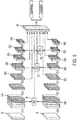
- the feature pyramid 48 is constructed by layer outputs, or convolution layers 54A, 56A, 58A, 60A, 62A, 64A associated with the map 50A, and convolution layers 54B, 56B, 58B, 60B, 62B, 64B associated with the map 50B.
- Map 50A generally mirrors map 50B since they are each associated with the same number of layers.
- the coordinated layers from each map 50A, 50B of the respective color image signal 34 and thermal image signal 36 are inputted into respective GFU's 66, 68, 70, 72, 74, 76.
- layers 54A, 54B are inputted into GFU 66
- layers 56A, 56B are inputted into GFU 68
- layers 58A, 58B are inputted into GFU 70
- layers 60A, 60B are inputted into GFU 72
- layers 62A, 62B are inputted into GFU 74
- layers 64A, 64B are inputted into GFU 76.
- Each GFU 66, 68, 70, 72, 74, 76 is configured to output a respective output 78, 80, 82, 84, 86, 88 to the feature pyramid 48.
- the GFU outputs are a joint combination of the SSD's 50A, 50B, and its dimension equals the dimension of one input. Therefore, the number of anchors (i.e., number of GFD's) from GFD-SSD maintain the same with a single SSD.
- anchors are pre-set potential locations and sizes for objects in the image.
- the location number could be hundreds, thousands, or more. During the process, the number is reduced, and the locations and sizes are updated.
- the GFU's 66, 68, 70, 72, 74, 76 (or a single GFU with multiple outputs) is the key component that adjusts the feature map combination between two modalities to form the feature pyramid 48.
- F C and F T are the corresponding feature maps 50A, 5B associated with, or from, the color and thermal SSDs 28, 30 or signals 34, 36, and F G is the concatenation of F C and F T .
- two 3 ⁇ 3 kernels ( w C , b C ) and ( W T , b T ) are applied on F G separately, followed by a Rectified Linear Unit (ReLU) activation function on each path.
- a C and A T denote the activation outputs.
- F F denotes the concatenation of the two summations, which is then passed to a 1 ⁇ 1 kernel ( w J , b J ) to generate the joint feature output F J .
- This method differs from more traditional methods in that ReLU is used instead of a sigmoid activation function to generate A C and A T , and then performing element-wise summation instead of the more traditional product operation on F C and F T .
- the output range of sigmoid function is (0, 1)
- multiplying a (0, 1) value on more traditional input feature maps is a complicated form of weighting mechanism.
- the present disclosure equivalently accomplishes this by using top detection layers outside GFU.
- the present method thus breaks the (0, 1) constraint by replacing the sigmoid with ReLU which has an output range (0, + ⁇ ), and by replacing the following product operation with summation.
- the two 3 ⁇ 3 kernels ( w C , b C ) and ( w T , b T ) in FIG. 3 are applied on the concatenated feature map F G .
- FIG. 4 a second embodiment of the GFU(s) is illustrated.
- the two 3 ⁇ 3 kernels ( w C , b C ) and ( w T , b T ) are not applied on the concatenated feature map F G , instead, the kernels are applied on F C and F T individually.
- the intuition for this alternative design is that the GFU represented in FIG. 3 keeps the original inputs and learns operational adjustments from their combination, whereas the GFU represented in FIG. 4 learns adjustments directly from the original input.
- the gated fusion structure shown in Figure 2 applies GFUs 66, 68, 70, 72, 74, 76 on all layers 54A-64A, 54B-64B of the feature maps 50A, 50B within the SSD's 50A, 50B (i.e., within the pyramid structure).
- the mixed fusion selects a subset of feature maps for gated fusion and keep the remaining features in stack fusion.
- a mixed-even fusion is illustrated in FIG. 5 .
- a mixed-odd fusion is illustrated in FIG. 6 .
- a mixed-early fusion is illustrate in FIG. 7 .
- a mixed-late fusion is illustrated in FIG. 8 .
- Each embodiment is dependent upon which layers are selected to use the GFUs.
- the mixed-even fusion illustrated in FIG. 5 applies GFUs 66, 70, 74 to the respective layers 56A, 56B, 58A, 58B, 62A, 62B (i.e., gates the layers), and the layers 56A, 56B, 60A, 60B, 64A, 64B are stacked.
- the mixed-odd fusion illustrated in FIG. 6 applies GFUs 68, 72, 76 to the respective layers 56A, 56B, 60A, 60B, 64A, 64B, and the layers 54A, 54B, 58A, 58B, 62A, 62B are stacked.
- the mixed-early fusion illustrated in FIG. 7 applies GFUs on shallower feature maps (i.e. layers) and the mixed-late fusion illustrated in FIG. 8 applies GFUs on deeper layers. Since the SSDs 28, 30 use pre-set anchors which are associated with the feature pyramid 48, mixed fusion variations can result in a different number of anchors.
- the single SSD has an extra convolution layer (not shown) in the feature pyramid 48. Therefore, we let the extra convolution layer be gated in mixed-even and the mixed-late fusion architectures, and stacked in mixed-odd and mixed-early fusion architectures.
- Computer readable program codes may include source codes, object codes, executable codes, and others.
- Computer readable mediums may be any type of media capable of being accessed by a computer, and may include Read Only Memory (ROM), Random Access Memory (RAM), a hard disk drive, a compact disc (CD), a digital video disc (DVD), or other non-transitory forms.
- the term “if' is, optionally, construed to mean “when” or “upon” or “in response to determining” or “in response to detecting,” depending on the context.
- the phrase “if it is determined” or “if [a stated condition or event] is detected” is, optionally, construed to mean “upon determining” or “in response to determining” or “upon detecting [the stated condition or event]” or “in response to detecting [the stated condition or event],” depending on the context.
- an application may be, but is not limited to, a process running on a processor, a processor, an object, an executable, a thread of execution, a program, and/or a computer.
- An application running on a server and the server may be a component.
- One or more applications may reside within a process and/or thread of execution and an application may be localized on one computer and/or distributed between two or more computers.
Landscapes
- Engineering & Computer Science (AREA)
- Theoretical Computer Science (AREA)
- Physics & Mathematics (AREA)
- General Physics & Mathematics (AREA)
- Multimedia (AREA)
- Computer Vision & Pattern Recognition (AREA)
- Evolutionary Computation (AREA)
- Data Mining & Analysis (AREA)
- Artificial Intelligence (AREA)
- Life Sciences & Earth Sciences (AREA)
- Signal Processing (AREA)
- Bioinformatics & Cheminformatics (AREA)
- Evolutionary Biology (AREA)
- General Engineering & Computer Science (AREA)
- Bioinformatics & Computational Biology (AREA)
- Health & Medical Sciences (AREA)
- General Health & Medical Sciences (AREA)
- Databases & Information Systems (AREA)
- Computing Systems (AREA)
- Human Computer Interaction (AREA)
- Medical Informatics (AREA)
- Software Systems (AREA)
- Optics & Photonics (AREA)
- Biodiversity & Conservation Biology (AREA)
- Biomedical Technology (AREA)
- Molecular Biology (AREA)
- Image Analysis (AREA)
Abstract
Description
- This patent application claims priority to
US Provisional Patent Application No. 62/737970, filed September 28, 2018 - The present disclosure relates to object detection systems, and more specifically, to a pedestrian detection system and method of operation.
- Pedestrian detection is a task for many applications including, for example, the area of autonomous driving of a vehicle. The detection of pedestrians is an important attribute of an autonomous vehicle before the vehicle may be deployed on urban streets. More currently, artificial intelligence, has made progress in the study of pedestrian detection. However, further improvements are desirable especially in environments such as weak illumination, far distance, and occlusion of pedestrians.
- Accordingly, it is desirable to further develop and improve object detection systems.
- An object detection system according to one, non-limiting, exemplary embodiment of the present disclosure includes color and infrared cameras, a controller-circuit, and instructions. The color and infrared cameras are configured to output respective color image and infrared image signals. The controller-circuit is in communication with the cameras, and includes a processor and a storage medium. The processor is configured to receive and transform the color image and infrared image signals into classification and location data associated with a detected object. The instructions are stored in the at least one storage medium and executed by the at least one processor, and are configured to utilize the color image and infrared image signals to form respective first and second maps. The first map has a first plurality of layers, and the second map has a second plurality of layers. Selected layers from each are paired and fused to form a feature pyramid that facilitates formulation of the classification and location data.
- In accordance with another embodiment, a method of detecting a pedestrian includes a step of receiving from a visual image sensor, a visual image signal indicative of a visual image of an area. The next step includes receiving from a thermal image sensor, a thermal image signal indicative of a thermal image of the area. The visual image and thermal image signals are then transformed into classification and localization data by a processor executing instructions that applies a gated fusion unit to detect a pedestrian in the area.
- In accordance with another embodiment, a controller-circuit facilitates detection of an object. The controller-circuit includes at least one processor and at least one storage medium. The processor is configured to receive a color image signal and a second image signal respectively received from a color camera and an image device. The processor executes instructions to transform the color image signal and the second image signal into respective first and second maps. The first map has a first plurality of feature layers, and the second map has a second plurality of feature layers. The selected feature layers from the first and second maps are paired and fused using gated fusion to at least in part form a feature pyramid that facilitates the transformation of the color image signal and the second image signal into classification data and location data associated with a detected object. The storage medium is configured to store the executable instructions retrieved by the at least one processor.
- These and other advantages and features will become more apparent from the following description taken in conjunction with the drawings.
- The subject matter which is regarded as the invention is particularly pointed out and distinctly claimed in the claims at the conclusion of the specification. The foregoing and other features, and advantages of the invention are apparent from the following detailed description taken in conjunction with the accompanying drawings in which:
-
FIG. 1 is a schematic of a vehicle utilizing an object detection system; -
FIG. 2 is a schematic illustrating a fusion architecture of the object detection system; -
FIG. 3 is a schematic illustrating a gated fusion unit of the object detection system; -
FIG. 4 is a schematic illustrating a second embodiment of a gated fusion unit; -
FIG. 5 is a schematic of a second embodiment of a fusion architecture; -
FIG. 6 is a schematic of a third embodiment of a fusion architecture; -
FIG. 7 , is a schematic of a fourth embodiment of a fusion architecture; and -
FIG. 8 is a schematic of a fifth embodiment of a fusion architecture. - Reference will now be made in detail to embodiments, examples of which are illustrated in the accompanying drawings. In the following detailed description, numerous specific details are set forth in order to provide a thorough understanding of the various described embodiments. However, it will be apparent to one of ordinary skill in the art that the various described embodiments may be practiced without these specific details. In other instances, well-known methods, procedures, components, circuits, and networks have not been described in detail so as not to unnecessarily obscure aspects of the embodiments.
- Referring now to the Figures, where the invention will be described with reference to specific embodiments, without limiting same, a
system 20 may include avehicle 22, which may be an autonomous vehicle, and an object detection system 24 (e.g., pedestrian detection system) that may be included as part of thevehicle 22 as illustrated inFIG. 1 . Although illustrated as a vehicle traveling upon a roadway, thevehicle 22 may be any form of transportation for people and/or cargo including marine vehicles, aviation vehicles, and others. - The
vehicle 22 may include at least one controller-circuit 26 and a plurality of sensors or detectors (i.e., three illustrated as 28, 30, 32). The controller-circuit 26 includes one ormore processors 33, and one or moreelectronic storage mediums 35. Theprocessor 33 is any combination of one or more of a central processing unit (CPU), multiprocessor, microcontroller unit (MCU), digital signal processor (DSP), application specific integrated circuit, and others capable of executing software instructions or otherwise controllable to behave according to predetermined logic. Thestorage medium 35 is, optionally, any combination of read and write memory (RAM) and read only memory (ROM). Thestorage medium 35 may also include persistent storage, which can be any single one, or combination of, solid state memory, magnetic memory, and optical memory storing a computer program (i.e., application) with software instructions. In one example, thestorage medium 35 may be non-transitory. - The multitude of sensors may include a visual light imaging sensor 28 (i.e., color camera), an infrared or thermal imaging sensor 30 (i.e., long-wavelength infrared sensor), a radar sensor or
detector 32, and others. Thesensors arrows circuit 26, and may each serve multiple functions. For example, one or more of thesensors system 20, orvehicle 22. Such systems may include a navigation system (e.g., satellite-based, GPS), a computer vision system, a radar system, a Light Detection and Ranging (LiDAR) system, a land-based system (e.g., beacon stations), and others. It is contemplated and understood that theinfrared sensor 30 may be replaced with a LiDAR sensor. - The
object detection system 24 may be configured to both recognize the presence of an object 39 (e.g., pedestrian) and locate the object with respect to thevehicle 22. In one embodiment, the entireobject detection system 24 may be carried by thevehicle 22. In other embodiments, computer instruction aspects and computer processing and/or data storage may be conducted remotely from the vehicle 22 (conducted as part of a remote server function, e.g., cloud). - In one embodiment, the
object detection system 24 includes at least two of the multitude ofsensors executable code 40, anddata files 42. In one example, theobject detection system 24 includes (or utilizes) the visuallight imaging sensor 28 and thethermal imaging sensor 30. Theobject detection system 24 includes theprocessor 33, or at least utilizes the processor, to execute thecomputer instruction 40, and includes thestorage medium 35, or at least utilizes thestorage medium 35, to store thecomputer instructions 40 anddata files 42. - In operation of the
object detection system 24, thesignals respective sensors circuit 26, and processed and transformed by theprocessor 33 utilizing thecomputer instructions 40 anddata file 42 stored in thestorage medium 35. Theprocessor 33, via theinstructions 40 of theobject detection system 24, may transform thesignals object classification 41 and an object location 43 (i.e., classification and location data) as part of the data file 42 (seeFIG. 2 ).Object classification 41 is the classification of each candidate or object into a foreground or background category. The object location 43 is the location upon a feature map (to be described below). - Utilizing, at least in-part, the classification and
location data 41, 43 derived from the transformed input signals 34, 36, the controller-circuit 26 may then output a signal 44 (e.g., command signal, information signal, and others) to one ormore devices 46 that may be external to the controller-circuit 26. Examples of such devices may include an information display screen for viewing by an occupant of thevehicle 22, a steering device, a braking device, an acceleration device, and others. - The
sensors SSD SSD convolution layer FIG. 2 ) features in a pyramid structure to detect objects with different scales. That is, VGG16, or the convolution layers 54A, 54B, generate several layers, and the SSD extends the convolution layers 54A, 54B to severalmore layers 56A-64A and 56B-64B. - Features are formulated in a pyramid structure which contains both high level semantic information as well as low level localization context. This is beneficial to detect small objects from shallow layers and recognize large objects from deeper layers. It is understood and contemplated that the
sensors computer instructions 40 and data file 42. - There generally exists a tradeoff between accuracy and speed among several modern object detectors, which may demonstrate a general conclusion that two-stage detectors achieve higher accuracy while one-stage detectors (i.e., SSD's) perform better in speed. In the present disclosure and in autonomous driving applications, which generally require real-time accurate detection, the network architecture of
system 20 is based on the one-stage detector and improves system accuracy to be comparable, or superior to, more conventional two-stage detectors. - SSD differs from Faster-RCNN in that its feature pyramid is constructed by multiple feature maps ranging from early to late stage convolutional layers. A typical "fusion" approach is to concatenate all feature maps from color and thermal modalities, which will double the number of anchors for the final classification layer. This is known as "stacked fusion."
- The "gated fusion" structure of the
object detection system 24 utilizes Gated Fusion Units (GFU's) that facilitate, or act as, an intermediate bridge between, for example, the color SSD and thermal SSD, which takes input from two feature maps and outputs a joint feature map without changing the size. The operation of the GFU is based on a gating mechanism endeavoring to keep the information delivered by reliable features while mitigating the effect of degraded features. - Referring to
FIGS. 1 and2 , theSSD hieratical pyramid 48 formation of its feature maps of the data file 42. Thehieratical pyramid 48 is generally composed ofconvolution layers 54A-64A and 54B-64B, where any single layer forms into a feature map. That is, the layers are relative to the model structure, and the feature maps are generated from the layers when input data is given. - The signal 34 (e.g., color image) is associated with, and evaluated by, the
SSD 50A, and the signal 36 (e.g., thermal image) is associated with, and evaluated by, theSSD 50B.Shallow layers deep layers deconvolutional layers - More specifically, the sizes of the feature maps, or layers, 54A-64A and 54B-64B are different, from high resolution to low. For example, layers 54A, 54B are each 300x300, and layers 64A, 64B are each 20x20. Since they are processed from the same image, an object exists in all of the layers, but in different scales (i.e., resolutions).
- Referring to
FIG. 2 , for theSSD feature pyramid 48 is constructed by layer outputs, orconvolution layers map 50A, and convolution layers 54B, 56B, 58B, 60B, 62B, 64B associated with themap 50B.Map 50A generally mirrorsmap 50B since they are each associated with the same number of layers. For gated fusion architecture, as best shown inFIG. 2 , the coordinated layers from eachmap color image signal 34 andthermal image signal 36 are inputted into respective GFU's 66, 68, 70, 72, 74, 76. More specifically, layers 54A, 54B are inputted intoGFU 66, layers 56A, 56B are inputted intoGFU 68, layers 58A, 58B are inputted intoGFU 70, layers 60A, 60B are inputted intoGFU 72, layers 62A, 62B are inputted intoGFU 74, and layers 64A, 64B are inputted intoGFU 76. - Each
GFU respective output 78, 80, 82, 84, 86, 88 to thefeature pyramid 48. The GFU outputs are a joint combination of the SSD's 50A, 50B, and its dimension equals the dimension of one input. Therefore, the number of anchors (i.e., number of GFD's) from GFD-SSD maintain the same with a single SSD. - Although not specifically illustrated, anchors are pre-set potential locations and sizes for objects in the image. The location number could be hundreds, thousands, or more. During the process, the number is reduced, and the locations and sizes are updated.
- The GFU's 66, 68, 70, 72, 74, 76 (or a single GFU with multiple outputs) is the key component that adjusts the feature map combination between two modalities to form the
feature pyramid 48. Referring toFIG. 3 , FC and FT are the corresponding feature maps 50A, 5B associated with, or from, the color andthermal SSDs - In this example, two 3×3 kernels (wC , bC ) and (WT, bT ) are applied on FG separately, followed by a Rectified Linear Unit (ReLU) activation function on each path. AC and AT denote the activation outputs. An element-wise summation on AC and AT with FC and FT respectively, is then performed. FF denotes the concatenation of the two summations, which is then passed to a 1 × 1 kernel (wJ , bJ ) to generate the joint feature output FJ . This method differs from more traditional methods in that ReLU is used instead of a sigmoid activation function to generate AC and AT, and then performing element-wise summation instead of the more traditional product operation on FC and FT. Since the output range of sigmoid function is (0, 1), multiplying a (0, 1) value on more traditional input feature maps is a complicated form of weighting mechanism. The present disclosure equivalently accomplishes this by using top detection layers outside GFU. The present method thus breaks the (0, 1) constraint by replacing the sigmoid with ReLU which has an output range (0, +∞), and by replacing the following product operation with summation. The two 3×3 kernels (wC , bC ) and (wT, bT ) in
FIG. 3 are applied on the concatenated feature map FG. - The operation of the GFU with regard to
FIG. 3 is summarized in the following equations:


- Referring to
FIG. 4 , a second embodiment of the GFU(s) is illustrated. In this embodiment, the two 3×3 kernels (wC , bC ) and (wT, bT ) are not applied on the concatenated feature map FG, instead, the kernels are applied on FC and FT individually. The intuition for this alternative design is that the GFU represented inFIG. 3 keeps the original inputs and learns operational adjustments from their combination, whereas the GFU represented inFIG. 4 learns adjustments directly from the original input. - The operation of the GFU with regard to
FIG. 4 is summarized in the following equations:



- The gated fusion structure shown in
Figure 2 appliesGFUs layers 54A-64A, 54B-64B of the feature maps 50A, 50B within the SSD's 50A, 50B (i.e., within the pyramid structure). Alternatively and referring toFIGS 5-8 , the mixed fusion selects a subset of feature maps for gated fusion and keep the remaining features in stack fusion. In one embodiment, a mixed-even fusion is illustrated inFIG. 5 . In another embodiment, a mixed-odd fusion is illustrated inFIG. 6 . In another embodiment, a mixed-early fusion is illustrate inFIG. 7 . In yet another embodiment, a mixed-late fusion is illustrated inFIG. 8 . Each embodiment is dependent upon which layers are selected to use the GFUs. - For example, the mixed-even fusion illustrated in
FIG. 5 , appliesGFUs respective layers layers FIG. 6 , appliesGFUs respective layers layers FIG. 7 applies GFUs on shallower feature maps (i.e. layers) and the mixed-late fusion illustrated inFIG. 8 applies GFUs on deeper layers. Since theSSDs feature pyramid 48, mixed fusion variations can result in a different number of anchors. - A larger number of anchors provides more potential object candidates, but also increases the required computational resources. For the input image size 512x512, as one example, the single SSD has an extra convolution layer (not shown) in the
feature pyramid 48. Therefore, we let the extra convolution layer be gated in mixed-even and the mixed-late fusion architectures, and stacked in mixed-odd and mixed-early fusion architectures. - The various functions described above may be implemented or supported by a computer program that is formed from computer readable program codes, and that is embodied in a non-transitory computer readable medium. Computer readable program codes may include source codes, object codes, executable codes, and others. Computer readable mediums may be any type of media capable of being accessed by a computer, and may include Read Only Memory (ROM), Random Access Memory (RAM), a hard disk drive, a compact disc (CD), a digital video disc (DVD), or other non-transitory forms.
- The terminology used in the description of the various described embodiments herein is for the purpose of describing particular embodiments only, and is not intended to be limiting. As used in the description of the various described embodiments and the appended claims, the singular forms "a", "an" and "the" are intended to include the plural forms as well, unless the context clearly indicates otherwise. It will also be understood that the term "and/or" as used herein refers to and encompasses any and all possible combinations of one or more of the associated listed items. It will be further understood that the terms "includes," "including," "comprises," and/or "comprising," when used in this specification, specify the presence of stated features, integers, steps, operations, elements, and/or components, but do not preclude the presence or addition of one or more other features, integers, steps, operations, elements, components, and/or groups thereof.
- As used herein, the term "if' is, optionally, construed to mean "when" or "upon" or "in response to determining" or "in response to detecting," depending on the context. Similarly, the phrase "if it is determined" or "if [a stated condition or event] is detected" is, optionally, construed to mean "upon determining" or "in response to determining" or "upon detecting [the stated condition or event]" or "in response to detecting [the stated condition or event]," depending on the context.
- Terms used herein such as component, application, module, system, and the like are intended to refer to a computer-related entity, either hardware, a combination of hardware and software, or software execution. By way of example, an application may be, but is not limited to, a process running on a processor, a processor, an object, an executable, a thread of execution, a program, and/or a computer. An application running on a server and the server, may be a component. One or more applications may reside within a process and/or thread of execution and an application may be localized on one computer and/or distributed between two or more computers.
- While the invention has been described in detail in connection with only a limited number of embodiments, it should be readily understood that the invention is not limited to such disclosed embodiments. Rather, the invention can be modified to incorporate any number of variations, alterations, substitutions or equivalent arrangements not heretofore described, but which are commensurate with the spirit and scope of the invention. Additionally, while various embodiments of the invention have been described, it is to be understood that aspects of the invention may include only some of the described embodiments. Accordingly, the invention is not to be seen as limited by the foregoing description.
Claims (15)
- An object detection system (20) comprising:a color camera (28) configured to render a color image of an area, the color image characterized as indicative of visible light from the area, and outputted by the color camera (28) as a color image signal (34);an infrared camera (30) configured to render an infrared image of the area, the infrared image characterized as indicative infrared light from the area, and outputted by the infrared camera (30) as an infrared image signal (36); anda controller-circuit (26) in communication with the color camera (28) and the infrared camera (30), the controller-circuit (26) including at least one processor (33) and at least one storage medium (35), the at least one processor (33) configured to receive and transform the color image and infrared image signals (34, 36) into classification data (41) and location data (43) associated with a detected object (39); andinstructions (40) stored in the at least one storage medium (35) and executed by the at least one processor (33), the instructions (40) configured to utilize the color image and infrared image signals (34, 36) to form respective first and second maps (50A, 50B), the first map (50A) having a first plurality of feature layers (54A-64A) and the second map (50B) having a second plurality of feature layers (54B-64B), and selected feature layers from the first and second maps (50A, 50B) are paired and fused using gated fusion to at least in part form a feature pyramid (48) facilitating the formulation of the classification and location data (41, 43).
- The object detection system set forth in claim 1, wherein the feature pyramid (48) is of equal dimension to at least one of the color image and the infrared image.
- The object detection system set forth in claim 2, wherein the object detection system (20) is a pedestrian detection system.
- The object detection system set forth in claim 2, wherein the infrared camera (30) is a thermal imaging sensor.
- The object detection system set forth in claim 2, wherein the color and infrared cameras (28, 30) are each at least a part of Deep Neural Network Detectors (DNNDs).
- The object detection system set forth in claim 5, wherein the first and second maps (50A, 50B) are Single Shot Detectors (SSDs).
- The object detection system set forth in claim 5, wherein the instructions (40) are associated with at least one gated fusion unit (68-76) configured to fuse selected layers from each one of the first and second maps (50A, 50B) to at least in-part form the feature pyramid (48).
- The object detection system set forth in claim 7, wherein the gated fusion unit (68-76) applies the following formulas:


- The object detection system set forth in claim 7, wherein the gated fusion unit (68-76) applies the following formulas:


- A method of detecting a pedestrian (39), the method comprising:receiving from a visual image sensor (28), a visual image signal (34) indicative of a visual image of an area;receiving from a thermal image sensor (30), a thermal image signal (36) indicative of a thermal image of the area; thetransforming the visual image signal (34) and the thermal image signal (36) into classification and localization data (41, 43) by a processor (33) executing instructions (40) that applies at least one gated fusion unit (66-76) to detect the pedestrian (39) in the area.
- The method set forth in claim 10, further comprising:transforming the visual image signal (34) and thermal image signal (36) into respective first and second plurality of feature layers (54A-64A, 54B-64B) using convolution layers by the instructions (40);pairing at least a portion of the feature layers (54A-64A, 54B-64B) between the first and second plurality of convolution layers; andapplying the at least one gated fusion unit (66-76) to the paired layers to generate at least one fused layer pair (78-88).
- The method set forth in claim 11, further comprising:
outputting the at least one fused layer pairs (78-88) by the at least one gated fusion unit (66-76) to a feature pyramid (48). - A controller-circuit (26) adapted to facilitate detection of an object (39), the controller-circuit comprising:at least one processor (33) configured to receive a color image signal (34) and a second image signal (36) respectively received from a color camera (28) and an image device (30), execute executable instructions (40) to transform the color image signal (34) and the second image signal (36) into respective first and second maps (50A, 50B), the first map (50A) having a first plurality of feature layers (54A-64A) and the second map (50B) having a second plurality of feature layers (54B-64B), and selected feature layers from the first and second maps (50A, 50B) are paired and fused using gated fusion to at least in part form a feature pyramid (48) to facilitate the transformation of the color image signal (34) and the second image signal (36) into classification data (41) and location data (43) associated with the detected object (39); andat least one storage medium (35) configured to store the executable instructions (40) retrieved by the at least one processor (33).
- The controller-circuit set forth in claim 13, wherein the feature pyramid (48) is of equal dimension to at least one of a color image indicative of the color image signal (34) and a second image indicative of the second image signal (36).
- The controller-circuit set forth in claim 14, wherein the second image is a LiDAR image taken by a LiDAR device as the image device (30).
Applications Claiming Priority (2)
| Application Number | Priority Date | Filing Date | Title |
|---|---|---|---|
| US201862737970P | 2018-09-28 | 2018-09-28 | |
| US16/270,105 US10936861B2 (en) | 2018-09-28 | 2019-02-07 | Object detection system of a vehicle |
Publications (2)
| Publication Number | Publication Date |
|---|---|
| EP3629231A1 true EP3629231A1 (en) | 2020-04-01 |
| EP3629231B1 EP3629231B1 (en) | 2024-08-14 |
Family
ID=67770449
Family Applications (1)
| Application Number | Title | Priority Date | Filing Date |
|---|---|---|---|
| EP19193779.6A Active EP3629231B1 (en) | 2018-09-28 | 2019-08-27 | Object detection system of a vehicle |
Country Status (3)
| Country | Link |
|---|---|
| US (1) | US10936861B2 (en) |
| EP (1) | EP3629231B1 (en) |
| CN (1) | CN110969079B (en) |
Cited By (2)
| Publication number | Priority date | Publication date | Assignee | Title |
|---|---|---|---|---|
| CN113955136A (en) * | 2021-09-02 | 2022-01-21 | 浙江图盛输变电工程有限公司温州科技分公司 | Unmanned aerial vehicle target hanging point calibration transfer station for automatic power grid inspection |
| CN116310764A (en) * | 2023-05-18 | 2023-06-23 | 西南交通大学 | A method and system for intelligent detection of pavement manhole cover |
Families Citing this family (15)
| Publication number | Priority date | Publication date | Assignee | Title |
|---|---|---|---|---|
| WO2021016596A1 (en) | 2019-07-25 | 2021-01-28 | Nvidia Corporation | Deep neural network for segmentation of road scenes and animate object instances for autonomous driving applications |
| US11885907B2 (en) | 2019-11-21 | 2024-01-30 | Nvidia Corporation | Deep neural network for detecting obstacle instances using radar sensors in autonomous machine applications |
| US12080078B2 (en) | 2019-11-15 | 2024-09-03 | Nvidia Corporation | Multi-view deep neural network for LiDAR perception |
| US11532168B2 (en) * | 2019-11-15 | 2022-12-20 | Nvidia Corporation | Multi-view deep neural network for LiDAR perception |
| US12050285B2 (en) | 2019-11-21 | 2024-07-30 | Nvidia Corporation | Deep neural network for detecting obstacle instances using radar sensors in autonomous machine applications |
| CN111080724B (en) * | 2019-12-17 | 2023-04-28 | 大连理工大学 | Fusion method of infrared light and visible light |
| WO2021259806A1 (en) | 2020-06-25 | 2021-12-30 | Signify Holding B.V. | System and methods to optimize neural networks using sensor fusion |
| EP3943969A1 (en) * | 2020-07-24 | 2022-01-26 | Aptiv Technologies Limited | Methods and systems for predicting a trajectory of an object |
| JP7132643B2 (en) * | 2020-11-17 | 2022-09-07 | 株式会社タナカ技研 | Acquisition Equipment, Image Production Method, and Program |
| KR20220085481A (en) | 2020-12-15 | 2022-06-22 | 삼성전자주식회사 | Method and apparatus of image processing |
| KR102590622B1 (en) * | 2021-04-02 | 2023-10-17 | 세종대학교산학협력단 | Object detection method and apparatus in multispectral domain using multi-label learning |
| CN113361322B (en) * | 2021-04-23 | 2022-09-27 | 山东大学 | Power line target detection method and device based on weighted deconvolution layer number improved DSSD algorithm and storage medium |
| CN113743521B (en) * | 2021-09-10 | 2023-06-27 | 中国科学院软件研究所 | Target detection method based on multi-scale context awareness |
| US12544932B2 (en) | 2023-03-09 | 2026-02-10 | Boston Dynamics, Inc. | Methods and apparatus for modeling loading dock environments |
| KR102803310B1 (en) * | 2024-05-23 | 2025-05-08 | 대한민국(방위사업청장) | Method and Apparatus for Object Detecting Using Multimodal Learning Models |
Family Cites Families (12)
| Publication number | Priority date | Publication date | Assignee | Title |
|---|---|---|---|---|
| US8379321B2 (en) * | 2009-03-05 | 2013-02-19 | Raytheon Canada Limited | Method and apparatus for accurate imaging with an extended depth of field |
| SI3170476T1 (en) * | 2009-07-10 | 2022-01-31 | Medicaltree Patent Ltd. | Implantable lubrication device |
| CN103455036B (en) * | 2012-06-05 | 2018-04-27 | 国家电网公司 | A kind of scene aerial patrol method and aircraft |
| KR102045841B1 (en) * | 2012-10-09 | 2019-11-18 | 삼성전자주식회사 | Method for creating an task-recommendation-icon in electronic apparatus and apparatus thereof |
| US8929600B2 (en) * | 2012-12-19 | 2015-01-06 | Microsoft Corporation | Action recognition based on depth maps |
| US10863098B2 (en) * | 2013-06-20 | 2020-12-08 | Microsoft Technology Licensing. LLC | Multimodal image sensing for region of interest capture |
| WO2016054779A1 (en) * | 2014-10-09 | 2016-04-14 | Microsoft Technology Licensing, Llc | Spatial pyramid pooling networks for image processing |
| US9542037B2 (en) * | 2015-03-08 | 2017-01-10 | Apple Inc. | Device, method, and user interface for processing intensity of touch contacts |
| US11042262B2 (en) * | 2017-02-01 | 2021-06-22 | Opentv, Inc. | Menu modification based on controller manipulation data |
| US10935978B2 (en) * | 2017-10-30 | 2021-03-02 | Nio Usa, Inc. | Vehicle self-localization using particle filters and visual odometry |
| US10824862B2 (en) * | 2017-11-14 | 2020-11-03 | Nuro, Inc. | Three-dimensional object detection for autonomous robotic systems using image proposals |
| US11500099B2 (en) * | 2018-03-14 | 2022-11-15 | Uatc, Llc | Three-dimensional object detection |
-
2019
- 2019-02-07 US US16/270,105 patent/US10936861B2/en active Active
- 2019-08-27 EP EP19193779.6A patent/EP3629231B1/en active Active
- 2019-09-27 CN CN201910923803.7A patent/CN110969079B/en active Active
Non-Patent Citations (2)
| Title |
|---|
| KIM JAEKYUM ET AL: "Robust Camera Lidar Sensor Fusion Via Deep Gated Information Fusion Network", 2018 IEEE INTELLIGENT VEHICLES SYMPOSIUM (IV), IEEE, 26 June 2018 (2018-06-26), pages 1620 - 1625, XP033423591, DOI: 10.1109/IVS.2018.8500711 * |
| YANG ZHENG ET AL: "GFD-SSD: Gated Fusion Double SSD for Multispectral Pedestrian Detection", ARXIV.ORG, CORNELL UNIVERSITY LIBRARY, 201 OLIN LIBRARY CORNELL UNIVERSITY ITHACA, NY 14853, 16 March 2019 (2019-03-16), XP081154331 * |
Cited By (4)
| Publication number | Priority date | Publication date | Assignee | Title |
|---|---|---|---|---|
| CN113955136A (en) * | 2021-09-02 | 2022-01-21 | 浙江图盛输变电工程有限公司温州科技分公司 | Unmanned aerial vehicle target hanging point calibration transfer station for automatic power grid inspection |
| CN113955136B (en) * | 2021-09-02 | 2024-04-05 | 浙江图盛输变电工程有限公司温州科技分公司 | Automatic unmanned aerial vehicle target hanging point calibration transfer station that patrols and examines of electric wire netting |
| CN116310764A (en) * | 2023-05-18 | 2023-06-23 | 西南交通大学 | A method and system for intelligent detection of pavement manhole cover |
| CN116310764B (en) * | 2023-05-18 | 2023-07-21 | 西南交通大学 | A method and system for intelligent detection of pavement manhole cover |
Also Published As
| Publication number | Publication date |
|---|---|
| CN110969079B (en) | 2023-09-19 |
| US10936861B2 (en) | 2021-03-02 |
| US20200104584A1 (en) | 2020-04-02 |
| EP3629231B1 (en) | 2024-08-14 |
| CN110969079A (en) | 2020-04-07 |
Similar Documents
| Publication | Publication Date | Title |
|---|---|---|
| EP3629231B1 (en) | Object detection system of a vehicle | |
| US12205292B2 (en) | Methods and systems for semantic segmentation of a point cloud | |
| US20260037790A1 (en) | Using decay parameters for inferencing with neural networks | |
| EP3881226B1 (en) | Object classification using extra-regional context | |
| US12125298B2 (en) | Efficient three-dimensional object detection from point clouds | |
| US10621476B1 (en) | Learning method and learning device for object detector based on reconfigurable network for optimizing customers' requirements such as key performance index using target object estimating network and target object merging network, and testing method and testing device using the same | |
| CN119151006A (en) | Enhancement of perceptual data using large language models in environment reconstruction systems and applications | |
| US10402692B1 (en) | Learning method and learning device for fluctuation-robust object detector based on CNN using target object estimating network adaptable to customers' requirements such as key performance index, and testing device using the same | |
| CN117727001A (en) | A BEV perception prediction method for targets around vehicles based on omnidirectional vision | |
| Li et al. | Detection of road objects based on camera sensors for autonomous driving in various traffic situations | |
| Ding et al. | TIR‐YOLO‐ADAS: A thermal infrared object detection framework for advanced driver assistance systems | |
| Jin | Comparing YOLO Models for Self-Driving Car Object Detection | |
| Jubair et al. | Attention-Enhanced YOLOV8 for accurate pedestrian detection and count estimation | |
| WO2025061553A1 (en) | Training an artificial neural network for carrying out a computer vision task | |
| Xu et al. | Road target detection in harsh environments based on improved YOLOv8n | |
| CN116311077A (en) | A pedestrian detection method and device based on multi-spectral fusion of saliency map | |
| KR20240098644A (en) | Method and System for Fusion of Radar Point Cloud and Radar Tensor and Data Processing in Artificial Intelligence | |
| CN116953702A (en) | Rotary target detection method and device based on deduction paradigm | |
| KR20240033564A (en) | Learning method and learning device for supporting autonomous driving by generating information on surrounding vehicles based on machine learning and testing method and testing device using the same | |
| US20250277665A1 (en) | Camera-radar spatio-spectral bev query to improve bev transformers for 3d perception tasks | |
| EP4604028A1 (en) | Active learning based on confusion matrix calibrated uncertainty for object classification in visual perception tasks in a vehicle | |
| US20260094428A1 (en) | Performing perception tasks by leveraging auto-regressive neural networks | |
| US20260048765A1 (en) | Joint signature-virtual field representation | |
| US20260065647A1 (en) | Automatic bias related dataset creation for machine learning training | |
| US20250166354A1 (en) | Dynamic adjustment of grid resolution in image processing |
Legal Events
| Date | Code | Title | Description |
|---|---|---|---|
| PUAI | Public reference made under article 153(3) epc to a published international application that has entered the european phase |
Free format text: ORIGINAL CODE: 0009012 |
|
| STAA | Information on the status of an ep patent application or granted ep patent |
Free format text: STATUS: THE APPLICATION HAS BEEN PUBLISHED |
|
| AK | Designated contracting states |
Kind code of ref document: A1 Designated state(s): AL AT BE BG CH CY CZ DE DK EE ES FI FR GB GR HR HU IE IS IT LI LT LU LV MC MK MT NL NO PL PT RO RS SE SI SK SM TR |
|
| AX | Request for extension of the european patent |
Extension state: BA ME |
|
| STAA | Information on the status of an ep patent application or granted ep patent |
Free format text: STATUS: REQUEST FOR EXAMINATION WAS MADE |
|
| 17P | Request for examination filed |
Effective date: 20200929 |
|
| RBV | Designated contracting states (corrected) |
Designated state(s): AL AT BE BG CH CY CZ DE DK EE ES FI FR GB GR HR HU IE IS IT LI LT LU LV MC MK MT NL NO PL PT RO RS SE SI SK SM TR |
|
| STAA | Information on the status of an ep patent application or granted ep patent |
Free format text: STATUS: EXAMINATION IS IN PROGRESS |
|
| 17Q | First examination report despatched |
Effective date: 20211223 |
|
| RAP3 | Party data changed (applicant data changed or rights of an application transferred) |
Owner name: APTIV TECHNOLOGIES LIMITED |
|
| REG | Reference to a national code |
Ref legal event code: R079 Free format text: PREVIOUS MAIN CLASS: G06K0009000000 Ipc: G06V0010800000 Ref country code: DE Ref document number: 602019056904 Country of ref document: DE |
|
| GRAP | Despatch of communication of intention to grant a patent |
Free format text: ORIGINAL CODE: EPIDOSNIGR1 |
|
| STAA | Information on the status of an ep patent application or granted ep patent |
Free format text: STATUS: GRANT OF PATENT IS INTENDED |
|
| RAP1 | Party data changed (applicant data changed or rights of an application transferred) |
Owner name: APTIV TECHNOLOGIES AG |
|
| RIC1 | Information provided on ipc code assigned before grant |
Ipc: G06V 10/44 20220101ALI20240415BHEP Ipc: G06V 10/82 20220101ALI20240415BHEP Ipc: G06V 20/58 20220101ALI20240415BHEP Ipc: G06V 10/80 20220101AFI20240415BHEP |
|
| INTG | Intention to grant announced |
Effective date: 20240430 |
|
| GRAS | Grant fee paid |
Free format text: ORIGINAL CODE: EPIDOSNIGR3 |
|
| P01 | Opt-out of the competence of the unified patent court (upc) registered |
Free format text: CASE NUMBER: APP_32537/2024 Effective date: 20240531 |
|
| GRAA | (expected) grant |
Free format text: ORIGINAL CODE: 0009210 |
|
| STAA | Information on the status of an ep patent application or granted ep patent |
Free format text: STATUS: THE PATENT HAS BEEN GRANTED |
|
| AK | Designated contracting states |
Kind code of ref document: B1 Designated state(s): AL AT BE BG CH CY CZ DE DK EE ES FI FR GB GR HR HU IE IS IT LI LT LU LV MC MK MT NL NO PL PT RO RS SE SI SK SM TR |
|
| REG | Reference to a national code |
Ref country code: GB Ref legal event code: FG4D |
|
| REG | Reference to a national code |
Ref country code: CH Ref legal event code: EP |
|
| REG | Reference to a national code |
Ref country code: DE Ref legal event code: R096 Ref document number: 602019056904 Country of ref document: DE |
|
| REG | Reference to a national code |
Ref country code: IE Ref legal event code: FG4D |
|
| RAP4 | Party data changed (patent owner data changed or rights of a patent transferred) |
Owner name: APTIV TECHNOLOGIES AG |
|
| REG | Reference to a national code |
Ref country code: LT Ref legal event code: MG9D |
|
| REG | Reference to a national code |
Ref country code: NL Ref legal event code: MP Effective date: 20240814 |
|
| PG25 | Lapsed in a contracting state [announced via postgrant information from national office to epo] |
Ref country code: NO Free format text: LAPSE BECAUSE OF FAILURE TO SUBMIT A TRANSLATION OF THE DESCRIPTION OR TO PAY THE FEE WITHIN THE PRESCRIBED TIME-LIMIT Effective date: 20241114 |
|
| REG | Reference to a national code |
Ref country code: AT Ref legal event code: MK05 Ref document number: 1714026 Country of ref document: AT Kind code of ref document: T Effective date: 20240814 |
|
| PG25 | Lapsed in a contracting state [announced via postgrant information from national office to epo] |
Ref country code: PL Free format text: LAPSE BECAUSE OF FAILURE TO SUBMIT A TRANSLATION OF THE DESCRIPTION OR TO PAY THE FEE WITHIN THE PRESCRIBED TIME-LIMIT Effective date: 20240814 Ref country code: NL Free format text: LAPSE BECAUSE OF FAILURE TO SUBMIT A TRANSLATION OF THE DESCRIPTION OR TO PAY THE FEE WITHIN THE PRESCRIBED TIME-LIMIT Effective date: 20240814 Ref country code: FI Free format text: LAPSE BECAUSE OF FAILURE TO SUBMIT A TRANSLATION OF THE DESCRIPTION OR TO PAY THE FEE WITHIN THE PRESCRIBED TIME-LIMIT Effective date: 20240814 Ref country code: GR Free format text: LAPSE BECAUSE OF FAILURE TO SUBMIT A TRANSLATION OF THE DESCRIPTION OR TO PAY THE FEE WITHIN THE PRESCRIBED TIME-LIMIT Effective date: 20241115 Ref country code: PT Free format text: LAPSE BECAUSE OF FAILURE TO SUBMIT A TRANSLATION OF THE DESCRIPTION OR TO PAY THE FEE WITHIN THE PRESCRIBED TIME-LIMIT Effective date: 20241216 |
|
| PG25 | Lapsed in a contracting state [announced via postgrant information from national office to epo] |
Ref country code: BG Free format text: LAPSE BECAUSE OF FAILURE TO SUBMIT A TRANSLATION OF THE DESCRIPTION OR TO PAY THE FEE WITHIN THE PRESCRIBED TIME-LIMIT Effective date: 20240814 |
|
| PG25 | Lapsed in a contracting state [announced via postgrant information from national office to epo] |
Ref country code: LV Free format text: LAPSE BECAUSE OF FAILURE TO SUBMIT A TRANSLATION OF THE DESCRIPTION OR TO PAY THE FEE WITHIN THE PRESCRIBED TIME-LIMIT Effective date: 20240814 |
|
| PG25 | Lapsed in a contracting state [announced via postgrant information from national office to epo] |
Ref country code: IS Free format text: LAPSE BECAUSE OF FAILURE TO SUBMIT A TRANSLATION OF THE DESCRIPTION OR TO PAY THE FEE WITHIN THE PRESCRIBED TIME-LIMIT Effective date: 20241214 Ref country code: AT Free format text: LAPSE BECAUSE OF FAILURE TO SUBMIT A TRANSLATION OF THE DESCRIPTION OR TO PAY THE FEE WITHIN THE PRESCRIBED TIME-LIMIT Effective date: 20240814 |
|
| PG25 | Lapsed in a contracting state [announced via postgrant information from national office to epo] |
Ref country code: HR Free format text: LAPSE BECAUSE OF FAILURE TO SUBMIT A TRANSLATION OF THE DESCRIPTION OR TO PAY THE FEE WITHIN THE PRESCRIBED TIME-LIMIT Effective date: 20240814 |
|
| PG25 | Lapsed in a contracting state [announced via postgrant information from national office to epo] |
Ref country code: RS Free format text: LAPSE BECAUSE OF FAILURE TO SUBMIT A TRANSLATION OF THE DESCRIPTION OR TO PAY THE FEE WITHIN THE PRESCRIBED TIME-LIMIT Effective date: 20241114 Ref country code: ES Free format text: LAPSE BECAUSE OF FAILURE TO SUBMIT A TRANSLATION OF THE DESCRIPTION OR TO PAY THE FEE WITHIN THE PRESCRIBED TIME-LIMIT Effective date: 20240814 |
|
| PG25 | Lapsed in a contracting state [announced via postgrant information from national office to epo] |
Ref country code: RS Free format text: LAPSE BECAUSE OF FAILURE TO SUBMIT A TRANSLATION OF THE DESCRIPTION OR TO PAY THE FEE WITHIN THE PRESCRIBED TIME-LIMIT Effective date: 20241114 Ref country code: PT Free format text: LAPSE BECAUSE OF FAILURE TO SUBMIT A TRANSLATION OF THE DESCRIPTION OR TO PAY THE FEE WITHIN THE PRESCRIBED TIME-LIMIT Effective date: 20241216 Ref country code: PL Free format text: LAPSE BECAUSE OF FAILURE TO SUBMIT A TRANSLATION OF THE DESCRIPTION OR TO PAY THE FEE WITHIN THE PRESCRIBED TIME-LIMIT Effective date: 20240814 Ref country code: NO Free format text: LAPSE BECAUSE OF FAILURE TO SUBMIT A TRANSLATION OF THE DESCRIPTION OR TO PAY THE FEE WITHIN THE PRESCRIBED TIME-LIMIT Effective date: 20241114 Ref country code: NL Free format text: LAPSE BECAUSE OF FAILURE TO SUBMIT A TRANSLATION OF THE DESCRIPTION OR TO PAY THE FEE WITHIN THE PRESCRIBED TIME-LIMIT Effective date: 20240814 Ref country code: LV Free format text: LAPSE BECAUSE OF FAILURE TO SUBMIT A TRANSLATION OF THE DESCRIPTION OR TO PAY THE FEE WITHIN THE PRESCRIBED TIME-LIMIT Effective date: 20240814 Ref country code: IS Free format text: LAPSE BECAUSE OF FAILURE TO SUBMIT A TRANSLATION OF THE DESCRIPTION OR TO PAY THE FEE WITHIN THE PRESCRIBED TIME-LIMIT Effective date: 20241214 Ref country code: HR Free format text: LAPSE BECAUSE OF FAILURE TO SUBMIT A TRANSLATION OF THE DESCRIPTION OR TO PAY THE FEE WITHIN THE PRESCRIBED TIME-LIMIT Effective date: 20240814 Ref country code: GR Free format text: LAPSE BECAUSE OF FAILURE TO SUBMIT A TRANSLATION OF THE DESCRIPTION OR TO PAY THE FEE WITHIN THE PRESCRIBED TIME-LIMIT Effective date: 20241115 Ref country code: FI Free format text: LAPSE BECAUSE OF FAILURE TO SUBMIT A TRANSLATION OF THE DESCRIPTION OR TO PAY THE FEE WITHIN THE PRESCRIBED TIME-LIMIT Effective date: 20240814 Ref country code: ES Free format text: LAPSE BECAUSE OF FAILURE TO SUBMIT A TRANSLATION OF THE DESCRIPTION OR TO PAY THE FEE WITHIN THE PRESCRIBED TIME-LIMIT Effective date: 20240814 Ref country code: BG Free format text: LAPSE BECAUSE OF FAILURE TO SUBMIT A TRANSLATION OF THE DESCRIPTION OR TO PAY THE FEE WITHIN THE PRESCRIBED TIME-LIMIT Effective date: 20240814 Ref country code: AT Free format text: LAPSE BECAUSE OF FAILURE TO SUBMIT A TRANSLATION OF THE DESCRIPTION OR TO PAY THE FEE WITHIN THE PRESCRIBED TIME-LIMIT Effective date: 20240814 |
|
| REG | Reference to a national code |
Ref country code: CH Ref legal event code: PL |
|
| PG25 | Lapsed in a contracting state [announced via postgrant information from national office to epo] |
Ref country code: SM Free format text: LAPSE BECAUSE OF FAILURE TO SUBMIT A TRANSLATION OF THE DESCRIPTION OR TO PAY THE FEE WITHIN THE PRESCRIBED TIME-LIMIT Effective date: 20240814 Ref country code: DK Free format text: LAPSE BECAUSE OF FAILURE TO SUBMIT A TRANSLATION OF THE DESCRIPTION OR TO PAY THE FEE WITHIN THE PRESCRIBED TIME-LIMIT Effective date: 20240814 Ref country code: RO Free format text: LAPSE BECAUSE OF FAILURE TO SUBMIT A TRANSLATION OF THE DESCRIPTION OR TO PAY THE FEE WITHIN THE PRESCRIBED TIME-LIMIT Effective date: 20240814 |
|
| PG25 | Lapsed in a contracting state [announced via postgrant information from national office to epo] |
Ref country code: LU Free format text: LAPSE BECAUSE OF NON-PAYMENT OF DUE FEES Effective date: 20240827 |
|
| PG25 | Lapsed in a contracting state [announced via postgrant information from national office to epo] |
Ref country code: EE Free format text: LAPSE BECAUSE OF FAILURE TO SUBMIT A TRANSLATION OF THE DESCRIPTION OR TO PAY THE FEE WITHIN THE PRESCRIBED TIME-LIMIT Effective date: 20240814 Ref country code: CH Free format text: LAPSE BECAUSE OF NON-PAYMENT OF DUE FEES Effective date: 20240831 |
|
| PG25 | Lapsed in a contracting state [announced via postgrant information from national office to epo] |
Ref country code: CZ Free format text: LAPSE BECAUSE OF FAILURE TO SUBMIT A TRANSLATION OF THE DESCRIPTION OR TO PAY THE FEE WITHIN THE PRESCRIBED TIME-LIMIT Effective date: 20240814 |
|
| PG25 | Lapsed in a contracting state [announced via postgrant information from national office to epo] |
Ref country code: SK Free format text: LAPSE BECAUSE OF FAILURE TO SUBMIT A TRANSLATION OF THE DESCRIPTION OR TO PAY THE FEE WITHIN THE PRESCRIBED TIME-LIMIT Effective date: 20240814 Ref country code: IT Free format text: LAPSE BECAUSE OF FAILURE TO SUBMIT A TRANSLATION OF THE DESCRIPTION OR TO PAY THE FEE WITHIN THE PRESCRIBED TIME-LIMIT Effective date: 20240814 |
|
| REG | Reference to a national code |
Ref country code: DE Ref legal event code: R097 Ref document number: 602019056904 Country of ref document: DE |
|
| PLBE | No opposition filed within time limit |
Free format text: ORIGINAL CODE: 0009261 |
|
| STAA | Information on the status of an ep patent application or granted ep patent |
Free format text: STATUS: NO OPPOSITION FILED WITHIN TIME LIMIT |
|
| REG | Reference to a national code |
Ref country code: BE Ref legal event code: MM Effective date: 20240831 |
|
| PG25 | Lapsed in a contracting state [announced via postgrant information from national office to epo] |
Ref country code: MC Free format text: LAPSE BECAUSE OF FAILURE TO SUBMIT A TRANSLATION OF THE DESCRIPTION OR TO PAY THE FEE WITHIN THE PRESCRIBED TIME-LIMIT Effective date: 20240814 |
|
| PG25 | Lapsed in a contracting state [announced via postgrant information from national office to epo] |
Ref country code: BE Free format text: LAPSE BECAUSE OF NON-PAYMENT OF DUE FEES Effective date: 20240831 |
|
| 26N | No opposition filed |
Effective date: 20250515 |
|
| PG25 | Lapsed in a contracting state [announced via postgrant information from national office to epo] |
Ref country code: IE Free format text: LAPSE BECAUSE OF NON-PAYMENT OF DUE FEES Effective date: 20240827 |
|
| PG25 | Lapsed in a contracting state [announced via postgrant information from national office to epo] |
Ref country code: SE Free format text: LAPSE BECAUSE OF FAILURE TO SUBMIT A TRANSLATION OF THE DESCRIPTION OR TO PAY THE FEE WITHIN THE PRESCRIBED TIME-LIMIT Effective date: 20240814 |
|
| PGFP | Annual fee paid to national office [announced via postgrant information from national office to epo] |
Ref country code: DE Payment date: 20250722 Year of fee payment: 7 |
|
| PGFP | Annual fee paid to national office [announced via postgrant information from national office to epo] |
Ref country code: GB Payment date: 20250813 Year of fee payment: 7 |
|
| PGFP | Annual fee paid to national office [announced via postgrant information from national office to epo] |
Ref country code: FR Payment date: 20250812 Year of fee payment: 7 |
|
| PG25 | Lapsed in a contracting state [announced via postgrant information from national office to epo] |
Ref country code: CY Free format text: LAPSE BECAUSE OF FAILURE TO SUBMIT A TRANSLATION OF THE DESCRIPTION OR TO PAY THE FEE WITHIN THE PRESCRIBED TIME-LIMIT; INVALID AB INITIO Effective date: 20190827 |
|
| PG25 | Lapsed in a contracting state [announced via postgrant information from national office to epo] |
Ref country code: HU Free format text: LAPSE BECAUSE OF FAILURE TO SUBMIT A TRANSLATION OF THE DESCRIPTION OR TO PAY THE FEE WITHIN THE PRESCRIBED TIME-LIMIT; INVALID AB INITIO Effective date: 20190827 |