EP3629122A2 - Processing method and apparatus for vehicle scene sequence tracking, and vehicle - Google Patents
Processing method and apparatus for vehicle scene sequence tracking, and vehicle Download PDFInfo
- Publication number
- EP3629122A2 EP3629122A2 EP19197092.0A EP19197092A EP3629122A2 EP 3629122 A2 EP3629122 A2 EP 3629122A2 EP 19197092 A EP19197092 A EP 19197092A EP 3629122 A2 EP3629122 A2 EP 3629122A2
- Authority
- EP
- European Patent Office
- Prior art keywords
- vehicle
- vehicle speed
- historical
- sequence
- current
- Prior art date
- Legal status (The legal status is an assumption and is not a legal conclusion. Google has not performed a legal analysis and makes no representation as to the accuracy of the status listed.)
- Granted
Links
Images




Classifications
-
- G—PHYSICS
- G05—CONTROLLING; REGULATING
- G05D—SYSTEMS FOR CONTROLLING OR REGULATING NON-ELECTRIC VARIABLES
- G05D1/00—Control of position, course, altitude or attitude of land, water, air or space vehicles, e.g. using automatic pilots
- G05D1/02—Control of position or course in two dimensions
- G05D1/021—Control of position or course in two dimensions specially adapted to land vehicles
- G05D1/0231—Control of position or course in two dimensions specially adapted to land vehicles using optical position detecting means
- G05D1/0246—Control of position or course in two dimensions specially adapted to land vehicles using optical position detecting means using a video camera in combination with image processing means
-
- G—PHYSICS
- G06—COMPUTING OR CALCULATING; COUNTING
- G06V—IMAGE OR VIDEO RECOGNITION OR UNDERSTANDING
- G06V20/00—Scenes; Scene-specific elements
- G06V20/50—Context or environment of the image
- G06V20/56—Context or environment of the image exterior to a vehicle by using sensors mounted on the vehicle
-
- B—PERFORMING OPERATIONS; TRANSPORTING
- B60—VEHICLES IN GENERAL
- B60W—CONJOINT CONTROL OF VEHICLE SUB-UNITS OF DIFFERENT TYPE OR DIFFERENT FUNCTION; CONTROL SYSTEMS SPECIALLY ADAPTED FOR HYBRID VEHICLES; ROAD VEHICLE DRIVE CONTROL SYSTEMS FOR PURPOSES NOT RELATED TO THE CONTROL OF A PARTICULAR SUB-UNIT
- B60W30/00—Purposes of road vehicle drive control systems not related to the control of a particular sub-unit, e.g. of systems using conjoint control of vehicle sub-units
-
- G—PHYSICS
- G05—CONTROLLING; REGULATING
- G05D—SYSTEMS FOR CONTROLLING OR REGULATING NON-ELECTRIC VARIABLES
- G05D1/00—Control of position, course, altitude or attitude of land, water, air or space vehicles, e.g. using automatic pilots
- G05D1/02—Control of position or course in two dimensions
- G05D1/021—Control of position or course in two dimensions specially adapted to land vehicles
- G05D1/0268—Control of position or course in two dimensions specially adapted to land vehicles using internal positioning means
- G05D1/0274—Control of position or course in two dimensions specially adapted to land vehicles using internal positioning means using mapping information stored in a memory device
-
- G—PHYSICS
- G06—COMPUTING OR CALCULATING; COUNTING
- G06T—IMAGE DATA PROCESSING OR GENERATION, IN GENERAL
- G06T7/00—Image analysis
- G06T7/20—Analysis of motion
-
- G—PHYSICS
- G06—COMPUTING OR CALCULATING; COUNTING
- G06T—IMAGE DATA PROCESSING OR GENERATION, IN GENERAL
- G06T7/00—Image analysis
- G06T7/70—Determining position or orientation of objects or cameras
-
- G—PHYSICS
- G06—COMPUTING OR CALCULATING; COUNTING
- G06V—IMAGE OR VIDEO RECOGNITION OR UNDERSTANDING
- G06V20/00—Scenes; Scene-specific elements
- G06V20/50—Context or environment of the image
- G06V20/56—Context or environment of the image exterior to a vehicle by using sensors mounted on the vehicle
- G06V20/58—Recognition of moving objects or obstacles, e.g. vehicles or pedestrians; Recognition of traffic objects, e.g. traffic signs, traffic lights or roads
- G06V20/586—Recognition of moving objects or obstacles, e.g. vehicles or pedestrians; Recognition of traffic objects, e.g. traffic signs, traffic lights or roads of parking space
-
- G—PHYSICS
- G06—COMPUTING OR CALCULATING; COUNTING
- G06T—IMAGE DATA PROCESSING OR GENERATION, IN GENERAL
- G06T2207/00—Indexing scheme for image analysis or image enhancement
- G06T2207/10—Image acquisition modality
- G06T2207/10016—Video; Image sequence
-
- G—PHYSICS
- G06—COMPUTING OR CALCULATING; COUNTING
- G06T—IMAGE DATA PROCESSING OR GENERATION, IN GENERAL
- G06T2207/00—Indexing scheme for image analysis or image enhancement
- G06T2207/30—Subject of image; Context of image processing
- G06T2207/30248—Vehicle exterior or interior
- G06T2207/30252—Vehicle exterior; Vicinity of vehicle
Definitions
- the embodiments of the present invention relate to the field of autonomous driving technology, and in particular, to a processing method and apparatus for vehicle scene sequence tracking, and a vehicle.
- the vehicle may be necessary for the vehicle to implement self-positioning and automatic parking based on a scene sequence tracking algorithm in some scenarios. For example, in a place such as an underground garage or a parking lot, the position information of a vehicle can be determined based on a scene sequence tracking algorithm, and then the control on the driving of the vehicle can be performed according to the position information of the vehicle. Before using a scene sequence tracking algorithm, input parameters of the algorithm need to be obtained first.
- the input parameters of a scene sequence tracking algorithm are mainly obtained based on experience, and the obtained input parameters are fixed values.
- the embodiments of the present invention provide a processing method and apparatus for vehicle scene sequence tracking, and a vehicle, to solve the problem of low running efficiency and accuracy of the scene sequence tracking in the prior art.
- a first aspect of the embodiments of the present invention provides a processing method for vehicle scene sequence tracking, including:
- the determining a vehicle speed ratio interval according to the current vehicle speed includes:
- the determining, according to the current vehicle speed, a length of a sequence to be tracked includes:
- the performing the scene sequence tracking according to the vehicle speed ratio interval, the length of the sequence to be tracked, the at least one frame of the current image, and pre-stored multiple frames of historical reference images of the vehicle, to obtain position information of the vehicle in the first area includes: taking the vehicle speed ratio interval, the length of the sequence to be tracked, the at least one frame of the current image, and the pre-stored multiple frames of the historical reference images of the vehicle as input parameters of a scene sequence tracking algorithm, to obtain the position information of the vehicle in the first area output by the scene sequence tracking algorithm.
- the method further includes: adjusting a driving state of the vehicle according to the position information of the vehicle in the first area.
- the method further includes: outputting prompt information corresponding to the position information according to the position information of the vehicle in the first area.
- a second aspect of the embodiments of the present invention provides a processing apparatus for vehicle scene sequence tracking, including:
- the first determining module includes:
- the first determining module further includes:
- the second determining module is specifically configured to: take the vehicle speed ratio interval, the length of the sequence to be tracked, the at least one frame of the current image, and the pre-stored multiple frames of the historical reference images of the vehicle as input parameters of a scene sequence tracking algorithm, to obtain the position information of the vehicle in the first area output by the scene sequence tracking algorithm.
- the apparatus further includes: an adjusting module, configured to adjust a driving state of the vehicle according to the position information of the vehicle in the first area.
- the apparatus further includes: an outputting module, configured to output prompt information corresponding to the position information according to the position information of the vehicle in the first area.
- a third aspect of the embodiments of the present invention provides a vehicle, including:
- a fourth aspect of the embodiments of the present invention provides a readable storage medium having a computer program stored therein, where the computer program is used to perform the method described in the first aspect above.
- the processing method and apparatus for vehicle scene sequence tracking and the vehicle provided by the embodiments of the present invention obtain a vehicle speed ratio interval and a length of a sequence to be tracked based on a current vehicle speed at which a vehicle is running, and perform scene sequence tracking based on the obtained vehicle speed ratio interval and the length of the sequence to be tracked to determine position information of the vehicle. Since the vehicle speed ratio interval and the length of the sequence to be tracked are obtained based on the current vehicle speed, the calculation parameters of the scene sequence tracking are dynamically adjusted by using the current vehicle speed of the vehicle, thereby being able to adapt to different running scenarios of the vehicle and ensuring that an accurate speed scanning range can still be quickly found when the vehicle speed changes greatly, and the speed scanning efficiency is greatly improved when the vehicle speed is relatively stable.
- the vehicle speed scanning range parameter in a scene tracking can be fixedly set to 0.8 ⁇ 1.2, that is, 2.4 ⁇ 3.6m/s, in consideration of fluctuation of the vehicle speed.
- the scanning range can then be fixedly adjusted to 0 ⁇ 1.2, that is, 0 ⁇ 3.6 m/s, in order to ensure the coverage ratio of the speed scanning range.
- the adjusted speed coverage is wider and can cope with complicated road conditions, however in most road sections, the vehicle still runs at a speed close to the speed in a reference video. Therefore, setting the excessive speed scanning range reduces the running efficiency and accuracy of the scene tracking.
- the length of the sequence to be tracked a fixed value of 20 to 40 frames can be selected as the length of the sequence to be tracked. This approach of using a fixed threshold has the following problems.
- the scene tracking algorithm still attempts to perform a local linear fitting with the fixed length of sequence to be tracked, resulting in the calculated motion trajectory failing to keep up with the position changes of the current vehicle.
- the fixed length of sequence to be tracked cannot provide enough linear trajectory constraints, which reduces the robustness of the positioning algorithm to scene changes.
- the fixed length of sequence to be tracked fixes the time domain sampling rate of the reference video sequence.
- an embodiment of the present invention provides a processing method for vehicle scene sequence tracking, which obtains a vehicle speed ratio interval and a length of sequence to be tracked based on a current vehicle speed at which a vehicle is running, and performs scene sequence tracking based on the obtained vehicle speed ratio interval and the length of sequence to be tracked to determine position information of the vehicle. Since the vehicle speed ratio interval and the length of sequence to be tracked are obtained based on the current vehicle speed, the calculation parameters of the scene sequence tracking are dynamically adjusted by using the current vehicle speed of the vehicle, thereby being able to adapt to different running scenarios of the vehicle and ensuring that an accurate speed scanning range can still be quickly found when the vehicle speed changes greatly, and the speed scanning efficiency is greatly improved when the vehicle speed is relatively stable.
- the processing method for vehicle scene sequence tracking provided by the embodiment of the present invention can be applied to scenarios such as vehicle self-positioning and automatic parking in places such as an underground garage, a parking lot, and the like.
- vehicle self-positioning and automatic parking in places such as an underground garage, a parking lot, and the like.
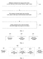
- FIG. 1 is a schematic flowchart of Embodiment 1 of a processing method for vehicle scene sequence tracking according to an embodiment of the present invention, where the execution subject of the method is a vehicle.
- the method includes: S101: Obtaining a current vehicle speed of a vehicle driving in a first area and at least one frame of current image taken.
- the first area may be an area where the vehicle is currently driving, and the first area can be identified by map information on the vehicle. For example, based on the map information, the vehicle can determine that it has entered a parking lot A, which can be the first area described above. Further, the precise position of the vehicle when driving inside the parking lot A can be determined based on the following process.
- wheel speed information may be obtained according to a vehicle speedometer through a controller area network (CAN) bus of the vehicle, and then the current vehicle speed of the vehicle is obtained according to the wheel speed information.
- CAN controller area network
- the current vehicle speed is an instantaneous vehicle speed at which the vehicle is currently driving.
- the vehicle can obtain the instantaneous vehicle speed of the vehicle and perform subsequent steps according to a certain smaller period, thereby continuously obtaining accurate position information of the vehicle in the first area.
- the at least one frame of the current image may be an image taken in real time at a current vehicle speed of the vehicle, i.e., within a current short time period, and the vehicle may use only one frame of the current image, or may use multiple frames of the current images for combination, and in combination with the other parameters described above, determine the position information of the vehicle in the first area.
- S102 Determining a vehicle speed ratio interval and a length of a sequence to be tracked according to the current vehicle speed, where the length of the sequence to be tracked is used to identify a number of frames of images used when performing scene sequence tracking.
- the vehicle speed ratio interval is a ratio interval obtained by a ratio of the current vehicle speed to a historical vehicle speed when the vehicle drives in the first area before the current time, and the specific process will be described in detail in the following embodiments.
- the ratio of the current vehicle speed to the historical vehicle speed is 1, and based on the ratio, the vehicle speed ratio interval can be obtained, for example, 0.8-1.2.
- S103 Performing the scene sequence tracking according to the vehicle speed ratio interval, the length of the sequence to be tracked, the at least one frame of the current image, and pre-stored multiple frames of historical reference images of the vehicle, to determine position information of the vehicle in the first area.
- the multiple frames of the historical reference images are images taken when the vehicle drives in the first area before the current time.
- the taken images can be preprocessed and marked to be used as historical reference images when the vehicle subsequently drives in the first area.
- the vehicle takes 10 frames of images in the first area, where 2 frames of images are taken at the parking space A, then the vehicle can select one frame of image with better quality from the 2 frames of images, and mark the selected one frame of image as "Parking space A", and so on. In this way, historical reference images are obtained by selecting and marking the above-described 10 frames of images.
- the position information in the first area obtained through the above process may be, for example, a parking space, a roadblock, a fork, a charge gate, and the like.
- the vehicle speed ratio interval and the length of the sequence to be tracked are obtained based on the current vehicle speed when the vehicle is running, and scene sequence tracking is performed based on the obtained vehicle speed ratio interval and the length of the sequence to be tracked to determine position information of the vehicle. Since the vehicle speed ratio interval and the length of the sequence to be tracked are obtained based on the current vehicle speed, the calculation parameters of the scene sequence tracking are dynamically adjusted by using the current vehicle speed of the vehicle, thereby being able to adapt to different running scenarios of the vehicle and ensuring that an accurate speed scanning range can still be quickly found when the vehicle speed changes greatly, and the speed scanning efficiency is greatly improved when the vehicle speed is relatively stable.
- the present embodiment relates to a process of determining the vehicle speed ratio interval based on the current vehicle speed of the vehicle.
- FIG. 2 is a schematic flowchart of Embodiment 2 of a processing method for vehicle scene sequence tracking according to an embodiment of the present invention.
- the process of determining the vehicle speed ratio interval based on the current vehicle speed of the vehicle may include: S201: Obtaining a historical vehicle speed of the vehicle at a time when each of the historical reference images is taken, a time domain sampling rate corresponding to the current image, and a time domain sampling rate corresponding to the historical reference image, and determining a ratio of the current vehicle speed to the historical vehicle speed.
- the historical vehicle speed of the vehicle at the time when each of the historical reference images is taken may be obtained at that time and the historical vehicle speed can be stored. Further, in this step, the corresponding historical vehicle speed of the vehicle when each of the historical reference images is taken may be directly obtained.
- the current time domain sampling rate and historical time domain sampling rate are used as the parameters for calculating, so that the calculated ratio of the current vehicle speed to the historical vehicle speed is more accurate.
- S202 Determining a scan width value according to the ratio of the current vehicle speed to the historical vehicle speed.
- the scan width value ⁇ k may be obtained according to k , for example, may be 0.2 times k .
- step S201 assuming that the vehicle speed ratio obtained in step S201 is 1, and ⁇ k is 0.2 times k , and thus ⁇ k is 0.2, it is known from the formula (2) below that the vehicle speed ratio interval k range is equal to (0.8, 1.2).
- S203 Determining the vehicle speed ratio interval, according to the ratio of the current vehicle speed to the historical vehicle speed and the scan width value.
- the present embodiment relates to a process of determining the length of the sequence to be tracked according to the current vehicle speed.
- FIG. 3 is a schematic flowchart of Embodiment 3 of a vehicle scene sequence tracking processing method according to an embodiment of the present invention.
- the process of determining the length of the sequence to be tracked according to the current vehicle speed may include: S301: Obtaining a historical vehicle speed of the vehicle at a time when each of the historical reference images is taken.
- the historical vehicle speed of the vehicle at the time when each of the historical reference images is taken may be obtained at that time and the historical vehicle speed can be stored. Further, in this step, the corresponding historical vehicle speed of the vehicle when each of the historical reference images is taken may be directly obtained.
- S302 Determining at least one length value according to the current vehicle speed and the historical vehicle speed.
- At least one L that satisfies the condition in the above formula which means, there may be more, and the maximum value of the at least one L that satisfies the above condition is selected as the length of the sequence to be tracked.
- an alternative implementation of the foregoing step S103 is: taking the vehicle speed ratio interval, the length of the sequence to be tracked, the at least one frame of the current image, and the pre-stored multiple frames of the historical reference images of the vehicle as input parameters of a scene sequence tracking algorithm, to obtain the position information of the vehicle in the first area output by the scene sequence tracking algorithm.
- the scene sequence tracking algorithm matches the current image and the historical reference image based on the foregoing vehicle speed ratio interval and the length of the sequence to be tracked to obtain a historical reference image with the highest matching degree with the current image, and further, according to mark information of the historical reference image with the highest matching degree, the position information corresponding to the current image is obtained, thereby determining the position information of the vehicle currently in the first area.
- the historical image with the highest matching degree with the current image is marked as a fork, it can then be determined that the vehicle is currently located at a fork.
- the vehicle can be controlled based on the position information.
- a driving state of the vehicle may be adjusted according to the position information of the vehicle in the first area.
- Adjusting the driving state of the vehicle may be, for example, reducing the vehicle speed, turning on the lights, switching directions, and the like.
- the vehicle speed can be reduced to ensure driving safety of the vehicle.
- prompt information corresponding to the location information may be output according to the position information of the vehicle in the first area.
- the prompt information corresponding to each position may be generated in advance.
- the prompt information may be to inform the user of the name of the position, or to remind the user to perform a corresponding operation.
- the current position of the vehicle is a charge gate, and then the user may be reminded, by voice or text, to pay.
- the current position of the vehicle is a roadblock, and then the vehicle can remind the user, by voice or text, about the presence of the roadblock and to pay attention to safety.
- FIG. 4 is a module structure diagram of a processing apparatus for vehicle scene sequence tracking according to an embodiment of the present invention. As shown in FIG. 4 , the apparatus includes:
- FIG. 5 is a module structure diagram of a processing apparatus for vehicle scene sequence tracking according to an embodiment of the present invention.
- the first determining module 402 includes:
- FIG. 6 is a module structure diagram of a processing apparatus for vehicle scene sequence tracking according to an embodiment of the present invention. As shown in FIG. 6 , the first determining module 402 further includes:
- the second determining module 403 is specifically configured to: take the vehicle speed ratio interval, the length of the sequence to be tracked, the at least one frame of the current image, and the pre-stored multiple frames of the historical reference images of the vehicle as input parameters of a scene sequence tracking algorithm, to obtain the position information of the vehicle in the first area output by the scene sequence tracking algorithm.
- FIG. 7 is a module structure diagram of a processing apparatus for vehicle scene sequence tracking according to an embodiment of the present invention. As shown in FIG. 7 , the apparatus further includes: an adjusting module 404, configured to adjust a driving state of the vehicle according to the position information of the vehicle in the first area.
- an adjusting module 404 configured to adjust a driving state of the vehicle according to the position information of the vehicle in the first area.
- FIG. 8 is a module structure diagram of a processing apparatus for vehicle scene sequence tracking according to an embodiment of the present invention. As shown in FIG. 8 , the apparatus further includes: an outputting module 405, configured to output prompt information corresponding to the position information according to the position information of the vehicle in the first area.
- an outputting module 405 configured to output prompt information corresponding to the position information according to the position information of the vehicle in the first area.
- FIG. 9 is a physical block diagram of a vehicle according to an embodiment of the present invention. As shown in FIG. 9 , the vehicle 900 includes:
- the aforementioned program may be stored in a computer readable storage medium.
- the program when executed, performs the steps of the foregoing method embodiments; and the foregoing storage medium includes various media that can store program codes, such as a ROM, a RAM, a magnetic disk, or an optical disk.
Landscapes
- Engineering & Computer Science (AREA)
- Physics & Mathematics (AREA)
- General Physics & Mathematics (AREA)
- Theoretical Computer Science (AREA)
- Multimedia (AREA)
- Radar, Positioning & Navigation (AREA)
- Automation & Control Theory (AREA)
- Computer Vision & Pattern Recognition (AREA)
- Aviation & Aerospace Engineering (AREA)
- Remote Sensing (AREA)
- Image Analysis (AREA)
- Transportation (AREA)
- Mechanical Engineering (AREA)
- Electromagnetism (AREA)
- Traffic Control Systems (AREA)
- Business, Economics & Management (AREA)
- Health & Medical Sciences (AREA)
- Artificial Intelligence (AREA)
- Evolutionary Computation (AREA)
- Game Theory and Decision Science (AREA)
- Medical Informatics (AREA)
- Image Processing (AREA)
Abstract
Description
- The embodiments of the present invention relate to the field of autonomous driving technology, and in particular, to a processing method and apparatus for vehicle scene sequence tracking, and a vehicle.
- In the field of intelligent driving, it may be necessary for the vehicle to implement self-positioning and automatic parking based on a scene sequence tracking algorithm in some scenarios. For example, in a place such as an underground garage or a parking lot, the position information of a vehicle can be determined based on a scene sequence tracking algorithm, and then the control on the driving of the vehicle can be performed according to the position information of the vehicle. Before using a scene sequence tracking algorithm, input parameters of the algorithm need to be obtained first.
- In the prior art, the input parameters of a scene sequence tracking algorithm are mainly obtained based on experience, and the obtained input parameters are fixed values.
- However, when the prior art approach is used, it can hardly adapt to vehicles running in different scenarios, resulting in low running efficiency and accuracy in some running scenarios.
- The embodiments of the present invention provide a processing method and apparatus for vehicle scene sequence tracking, and a vehicle, to solve the problem of low running efficiency and accuracy of the scene sequence tracking in the prior art.
- A first aspect of the embodiments of the present invention provides a processing method for vehicle scene sequence tracking, including:
- obtaining a current vehicle speed of a vehicle driving in a first area and at least one frame of current image taken;
- determining a vehicle speed ratio interval and a length of a sequence to be tracked according to the current vehicle speed, where the length of the sequence to be tracked is used to identify a number of frames of images used when performing scene sequence tracking; and
- performing the scene sequence tracking according to the vehicle speed ratio interval, the length of the sequence to be tracked, the at least one frame of the current image, and pre-stored multiple frames of historical reference images of the vehicle, to obtain position information of the vehicle in the first area.
- Further, the determining a vehicle speed ratio interval according to the current vehicle speed includes:
- obtaining a historical vehicle speed of the vehicle at a time when each of the historical reference images is taken, a time domain sampling rate corresponding to the current image, and a time domain sampling rate corresponding to the historical reference image, and determining a ratio of the current vehicle speed to the historical vehicle speed;
- determining a scan width value according to the ratio of the current vehicle speed to the historical vehicle speed; and
- determining, according to the ratio of the current vehicle speed to the historical vehicle speed, and the scan width value, the vehicle speed ratio interval.
- Further, the determining, according to the current vehicle speed, a length of a sequence to be tracked includes:
- obtaining a historical vehicle speed of the vehicle at a time when each of the historical reference images is taken;
- determining at least one length value according to the current vehicle speed and the historical vehicle speed; and
- taking a maximum of the at least one length value as the length of the sequence to be tracked.
- Further, the performing the scene sequence tracking according to the vehicle speed ratio interval, the length of the sequence to be tracked, the at least one frame of the current image, and pre-stored multiple frames of historical reference images of the vehicle, to obtain position information of the vehicle in the first area includes:
taking the vehicle speed ratio interval, the length of the sequence to be tracked, the at least one frame of the current image, and the pre-stored multiple frames of the historical reference images of the vehicle as input parameters of a scene sequence tracking algorithm, to obtain the position information of the vehicle in the first area output by the scene sequence tracking algorithm. - Further, the method further includes:
adjusting a driving state of the vehicle according to the position information of the vehicle in the first area. - Further, the method further includes:
outputting prompt information corresponding to the position information according to the position information of the vehicle in the first area. - A second aspect of the embodiments of the present invention provides a processing apparatus for vehicle scene sequence tracking, including:
- an obtaining module, configured to obtain a current vehicle speed of a vehicle driving in a first area and at least one frame of current image taken;
- a first determining module, configured to determine a vehicle speed ratio interval and a length of a sequence to be tracked according to the current vehicle speed, where the length of the sequence to be tracked is used to identify a number of frames of images used when performing scene sequence tracking; and
- a second determining module, configured to perform the scene sequence tracking according to the vehicle speed ratio interval, the length of the sequence to be tracked, the at least one frame of the current image, and pre-stored multiple frames of historical reference images of the vehicle, to obtain position information of the vehicle in the first area.
- Further, the first determining module includes:
- a first determining unit, configured to obtain a historical vehicle speed of the vehicle at a time when each of the historical reference images is taken, a time domain sampling rate corresponding to the current image, and a time domain sampling rate corresponding to the historical reference image, and determine a ratio of the current vehicle speed to the historical vehicle speed;
- a second determining unit, configured to determine a scan width value according to the ratio of the current vehicle speed to the historical vehicle speed; and
- a third determining unit, configured to determine, according to the ratio of the current vehicle speed to the historical vehicle speed, and the scan width value, the vehicle speed ratio interval.
- Further, the first determining module further includes:
- an obtaining unit, configured to obtain a historical vehicle speed of the vehicle at a time when the historical reference image is taken;
- a fourth determining unit, configured to determine at least one length value according to the current vehicle speed and the historical vehicle speed; and
- a fifth determining unit, configured to take a maximum of the at least one length value as the length of the sequence to be tracked.
- Further, the second determining module is specifically configured to:
take the vehicle speed ratio interval, the length of the sequence to be tracked, the at least one frame of the current image, and the pre-stored multiple frames of the historical reference images of the vehicle as input parameters of a scene sequence tracking algorithm, to obtain the position information of the vehicle in the first area output by the scene sequence tracking algorithm. - Further, the apparatus further includes:
an adjusting module, configured to adjust a driving state of the vehicle according to the position information of the vehicle in the first area. - Further, the apparatus further includes:
an outputting module, configured to output prompt information corresponding to the position information according to the position information of the vehicle in the first area. - A third aspect of the embodiments of the present invention provides a vehicle, including:
- a memory, configured to store program instructions;
- a processor, configured to call and execute the program instructions in the memory to perform the method steps described in the first aspect above.
- A fourth aspect of the embodiments of the present invention provides a readable storage medium having a computer program stored therein, where the computer program is used to perform the method described in the first aspect above.
- The processing method and apparatus for vehicle scene sequence tracking and the vehicle provided by the embodiments of the present invention obtain a vehicle speed ratio interval and a length of a sequence to be tracked based on a current vehicle speed at which a vehicle is running, and perform scene sequence tracking based on the obtained vehicle speed ratio interval and the length of the sequence to be tracked to determine position information of the vehicle. Since the vehicle speed ratio interval and the length of the sequence to be tracked are obtained based on the current vehicle speed, the calculation parameters of the scene sequence tracking are dynamically adjusted by using the current vehicle speed of the vehicle, thereby being able to adapt to different running scenarios of the vehicle and ensuring that an accurate speed scanning range can still be quickly found when the vehicle speed changes greatly, and the speed scanning efficiency is greatly improved when the vehicle speed is relatively stable.
- In order to illustrate the technical solutions in the present invention or the prior art more clearly, the drawings required in the description of the embodiments or the prior art will be briefly described below. Obviously, the drawings in the following description are only some embodiments of the present invention, and other drawings can be obtained according to these drawings by those skilled in the art without inventive efforts.
-
FIG. 1 is a schematic flowchart of Embodiment 1 of a processing method for vehicle scene sequence tracking according to an embodiment of the present invention; -
FIG. 2 is a schematic flowchart of Embodiment 2 of a processing method for vehicle scene sequence tracking according to an embodiment of the present invention; -
FIG. 3 is a schematic flowchart of Embodiment 3 of a processing method for vehicle scene sequence tracking according to an embodiment of the present invention; -
FIG. 4 is a module structure diagram of a processing apparatus for vehicle scene sequence tracking according to an embodiment of the present invention; -
FIG. 5 is a module structure diagram of a processing apparatus for vehicle scene sequence tracking according to an embodiment of the present invention; -
FIG. 6 is a module structure diagram of a processing apparatus for vehicle scene sequence tracking according to an embodiment of the present invention; -
FIG. 7 is a module structure diagram of a processing apparatus for vehicle scene sequence tracking according to an embodiment of the present invention; -
FIG. 8 is a module structure diagram of a processing apparatus for vehicle scene sequence tracking according to an embodiment of the present invention; -
FIG. 9 is a physical block diagram of a vehicle according to an embodiment of the present invention. - In order to make the objectives, technical solutions, and advantages of the embodiments of the present invention more clear, the technical solutions in the embodiments of the present invention will be clearly and completely described in the following with reference to the accompanying drawings in the embodiments of the present invention. It is obvious that the described embodiments are only a part of the embodiments of the present invention, but not all embodiments. All other embodiments obtained by those skilled in the art based on the embodiments of the present invention without inventive efforts are within the scope of the present invention.
- The terms "first", "second" and the like in the embodiments of the present invention and accompanying drawings are used to distinguish similar objects and not necessarily used to describe a specific order or an order of priority. It should be understood that the data so used is interchangeable where appropriate so that the embodiments of the present invention described herein can be implemented in an order other than those illustrated or described herein.
- In the prior art, input parameters of a scene sequence tracking algorithm are mainly obtained based on experience, and the obtained input parameters are fixed values. These input parameters with fixed values have high running efficiency and accuracy only in some scenarios, but cannot adapt to different running scenarios of the vehicle. In an example, for the speed scanning range parameter, according to a preset vehicle speed ratio 1 (the reference vehicle speed is 3 m/s), the vehicle speed scanning range parameter in a scene tracking can be fixedly set to 0.8∼1.2, that is, 2.4∼3.6m/s, in consideration of fluctuation of the vehicle speed. However, if the current vehicle driving environment is complicated and pulling over is included in the running process, the scanning range can then be fixedly adjusted to 0∼1.2, that is, 0∼3.6 m/s, in order to ensure the coverage ratio of the speed scanning range. Although the adjusted speed coverage is wider and can cope with complicated road conditions, however in most road sections, the vehicle still runs at a speed close to the speed in a reference video. Therefore, setting the excessive speed scanning range reduces the running efficiency and accuracy of the scene tracking. In another example, for the parameter, the length of the sequence to be tracked, a fixed value of 20 to 40 frames can be selected as the length of the sequence to be tracked. This approach of using a fixed threshold has the following problems. First, when the current vehicle speed changes greatly, the scene tracking algorithm still attempts to perform a local linear fitting with the fixed length of sequence to be tracked, resulting in the calculated motion trajectory failing to keep up with the position changes of the current vehicle. Secondly, when the scene changes greatly, the fixed length of sequence to be tracked cannot provide enough linear trajectory constraints, which reduces the robustness of the positioning algorithm to scene changes. Again, the fixed length of sequence to be tracked fixes the time domain sampling rate of the reference video sequence. When replacing with a reference video sequence of a different time domain sampling rate, it is necessary to manually re-adjust the length of sequence to be tracked appropriately, and the algorithm lacks adaptive capability. Therefore, the existing method is not able to adapt to vehicles running in different scenarios, resulting in lower running efficiency and accuracy in some running scenarios.
- Based on the above problems, an embodiment of the present invention provides a processing method for vehicle scene sequence tracking, which obtains a vehicle speed ratio interval and a length of sequence to be tracked based on a current vehicle speed at which a vehicle is running, and performs scene sequence tracking based on the obtained vehicle speed ratio interval and the length of sequence to be tracked to determine position information of the vehicle. Since the vehicle speed ratio interval and the length of sequence to be tracked are obtained based on the current vehicle speed, the calculation parameters of the scene sequence tracking are dynamically adjusted by using the current vehicle speed of the vehicle, thereby being able to adapt to different running scenarios of the vehicle and ensuring that an accurate speed scanning range can still be quickly found when the vehicle speed changes greatly, and the speed scanning efficiency is greatly improved when the vehicle speed is relatively stable.
- The processing method for vehicle scene sequence tracking provided by the embodiment of the present invention can be applied to scenarios such as vehicle self-positioning and automatic parking in places such as an underground garage, a parking lot, and the like. In these scenarios, regardless of the speed at which the vehicle is driving, it is possible to dynamically derive the vehicle speed ratio interval and the length of the sequence to be tracked that match the vehicle speed, to determine a precise position of the vehicle at the above places, for example, the vehicle is currently located at a certain parking space in an underground garage.
-
FIG. 1 is a schematic flowchart of Embodiment 1 of a processing method for vehicle scene sequence tracking according to an embodiment of the present invention, where the execution subject of the method is a vehicle. As shown inFIG. 1 , the method includes:
S101: Obtaining a current vehicle speed of a vehicle driving in a first area and at least one frame of current image taken. - Optionally, the first area may be an area where the vehicle is currently driving, and the first area can be identified by map information on the vehicle. For example, based on the map information, the vehicle can determine that it has entered a parking lot A, which can be the first area described above. Further, the precise position of the vehicle when driving inside the parking lot A can be determined based on the following process.
- Optionally, wheel speed information may be obtained according to a vehicle speedometer through a controller area network (CAN) bus of the vehicle, and then the current vehicle speed of the vehicle is obtained according to the wheel speed information.
- The current vehicle speed is an instantaneous vehicle speed at which the vehicle is currently driving. In a specific implementation process, the vehicle can obtain the instantaneous vehicle speed of the vehicle and perform subsequent steps according to a certain smaller period, thereby continuously obtaining accurate position information of the vehicle in the first area.
- Optionally, the at least one frame of the current image may be an image taken in real time at a current vehicle speed of the vehicle, i.e., within a current short time period, and the vehicle may use only one frame of the current image, or may use multiple frames of the current images for combination, and in combination with the other parameters described above, determine the position information of the vehicle in the first area.
- S102: Determining a vehicle speed ratio interval and a length of a sequence to be tracked according to the current vehicle speed, where the length of the sequence to be tracked is used to identify a number of frames of images used when performing scene sequence tracking.
- Optionally, the vehicle speed ratio interval is a ratio interval obtained by a ratio of the current vehicle speed to a historical vehicle speed when the vehicle drives in the first area before the current time, and the specific process will be described in detail in the following embodiments.
- Exemplarily, assuming that the current vehicle speed is 3 m/s and the historical vehicle speed is also 3 m/s, then the ratio of the current vehicle speed to the historical vehicle speed is 1, and based on the ratio, the vehicle speed ratio interval can be obtained, for example, 0.8-1.2.
- S103: Performing the scene sequence tracking according to the vehicle speed ratio interval, the length of the sequence to be tracked, the at least one frame of the current image, and pre-stored multiple frames of historical reference images of the vehicle, to determine position information of the vehicle in the first area.
- Optionally, the multiple frames of the historical reference images are images taken when the vehicle drives in the first area before the current time. Optionally, after the vehicle drives in the first area for the first time and images are taken at various positions, the taken images can be preprocessed and marked to be used as historical reference images when the vehicle subsequently drives in the first area. Exemplarily, the vehicle takes 10 frames of images in the first area, where 2 frames of images are taken at the parking space A, then the vehicle can select one frame of image with better quality from the 2 frames of images, and mark the selected one frame of image as "Parking space A", and so on. In this way, historical reference images are obtained by selecting and marking the above-described 10 frames of images.
- Exemplarily, the position information in the first area obtained through the above process may be, for example, a parking space, a roadblock, a fork, a charge gate, and the like.
- In the embodiment, the vehicle speed ratio interval and the length of the sequence to be tracked are obtained based on the current vehicle speed when the vehicle is running, and scene sequence tracking is performed based on the obtained vehicle speed ratio interval and the length of the sequence to be tracked to determine position information of the vehicle. Since the vehicle speed ratio interval and the length of the sequence to be tracked are obtained based on the current vehicle speed, the calculation parameters of the scene sequence tracking are dynamically adjusted by using the current vehicle speed of the vehicle, thereby being able to adapt to different running scenarios of the vehicle and ensuring that an accurate speed scanning range can still be quickly found when the vehicle speed changes greatly, and the speed scanning efficiency is greatly improved when the vehicle speed is relatively stable.
- On the basis of the above embodiment, the present embodiment relates to a process of determining the vehicle speed ratio interval based on the current vehicle speed of the vehicle.
-
FIG. 2 is a schematic flowchart of Embodiment 2 of a processing method for vehicle scene sequence tracking according to an embodiment of the present invention. As shown inFIG. 2 , the process of determining the vehicle speed ratio interval based on the current vehicle speed of the vehicle may include:
S201: Obtaining a historical vehicle speed of the vehicle at a time when each of the historical reference images is taken, a time domain sampling rate corresponding to the current image, and a time domain sampling rate corresponding to the historical reference image, and determining a ratio of the current vehicle speed to the historical vehicle speed. - Optionally, the historical vehicle speed of the vehicle at the time when each of the historical reference images is taken may be obtained at that time and the historical vehicle speed can be stored. Further, in this step, the corresponding historical vehicle speed of the vehicle when each of the historical reference images is taken may be directly obtained.
- Optionally, the ratio of the current vehicle speed to the historical vehicle speed may be calculated by the following formula (1):

- In this step, when calculating the ratio of the current vehicle speed to the historical vehicle speed, the current time domain sampling rate and historical time domain sampling rate are used as the parameters for calculating, so that the calculated ratio of the current vehicle speed to the historical vehicle speed is more accurate.
- S202: Determining a scan width value according to the ratio of the current vehicle speed to the historical vehicle speed.
- Optionally, the scan width value Δk may be obtained according to k, for example, may be 0.2 times k.
- Exemplarily, assuming that the vehicle speed ratio obtained in step S201 is 1, and Δk is 0.2 times k, and thus Δk is 0.2, it is known from the formula (2) below that the vehicle speed ratio interval krange is equal to (0.8, 1.2).
- S203: Determining the vehicle speed ratio interval, according to the ratio of the current vehicle speed to the historical vehicle speed and the scan width value.
- Optionally, the above-described vehicle speed ratio interval may be expressed by the following formula (2):

- On the basis of the above embodiment, the present embodiment relates to a process of determining the length of the sequence to be tracked according to the current vehicle speed.
-
FIG. 3 is a schematic flowchart of Embodiment 3 of a vehicle scene sequence tracking processing method according to an embodiment of the present invention. As shown inFIG. 3 , the process of determining the length of the sequence to be tracked according to the current vehicle speed may include:
S301: Obtaining a historical vehicle speed of the vehicle at a time when each of the historical reference images is taken. - Optionally, the historical vehicle speed of the vehicle at the time when each of the historical reference images is taken may be obtained at that time and the historical vehicle speed can be stored. Further, in this step, the corresponding historical vehicle speed of the vehicle when each of the historical reference images is taken may be directly obtained.
- S302: Determining at least one length value according to the current vehicle speed and the historical vehicle speed.
- S303: Taking a maximum of the at least one length value as the length of the sequence to be tracked.
- Optionally, the length of the sequence to be tracked is determined by the following formula (3):

- There is at least one L that satisfies the condition in the above formula, which means, there may be more, and the maximum value of the at least one L that satisfies the above condition is selected as the length of the sequence to be tracked.
- In another embodiment, an alternative implementation of the foregoing step S103 is:
taking the vehicle speed ratio interval, the length of the sequence to be tracked, the at least one frame of the current image, and the pre-stored multiple frames of the historical reference images of the vehicle as input parameters of a scene sequence tracking algorithm, to obtain the position information of the vehicle in the first area output by the scene sequence tracking algorithm. - Optionally, the scene sequence tracking algorithm matches the current image and the historical reference image based on the foregoing vehicle speed ratio interval and the length of the sequence to be tracked to obtain a historical reference image with the highest matching degree with the current image, and further, according to mark information of the historical reference image with the highest matching degree, the position information corresponding to the current image is obtained, thereby determining the position information of the vehicle currently in the first area.
- Exemplarily, the historical image with the highest matching degree with the current image is marked as a fork, it can then be determined that the vehicle is currently located at a fork.
- On the basis of obtaining the position information of the vehicle in the first area through the above embodiment, further, the vehicle can be controlled based on the position information.
- In an optional manner, a driving state of the vehicle may be adjusted according to the position information of the vehicle in the first area.
- Adjusting the driving state of the vehicle may be, for example, reducing the vehicle speed, turning on the lights, switching directions, and the like.
- Exemplarily, if it is determined by the foregoing process that the vehicle is located at a fork, the vehicle speed can be reduced to ensure driving safety of the vehicle.
- In another alternative manner, prompt information corresponding to the location information may be output according to the position information of the vehicle in the first area.
- Optionally, the prompt information corresponding to each position may be generated in advance. The prompt information may be to inform the user of the name of the position, or to remind the user to perform a corresponding operation.
- In an example, the current position of the vehicle is a charge gate, and then the user may be reminded, by voice or text, to pay.
- In another example, the current position of the vehicle is a roadblock, and then the vehicle can remind the user, by voice or text, about the presence of the roadblock and to pay attention to safety.
-
FIG. 4 is a module structure diagram of a processing apparatus for vehicle scene sequence tracking according to an embodiment of the present invention. As shown inFIG. 4 , the apparatus includes: - an obtaining
module 401, configured to obtain a current vehicle speed of a vehicle driving in a first area and at least one frame of current image taken; - a first determining
module 402, configured to determine a vehicle speed ratio interval and a length of a sequence to be tracked, according to the current vehicle speed, where the length of the sequence to be tracked is used to identify a number of frames of images used when performing scene sequence tracking; and - a second determining
module 403, configured to perform the scene sequence tracking according to the vehicle speed ratio interval, the length of the sequence to be tracked, the at least one frame of the current image, and pre-stored multiple frames of historical reference images of the vehicle, to obtain position information of the vehicle in the first area. - The apparatus is used to implement the foregoing method embodiment, and the implementation principle and technical effects are similar, and details are not described herein again.
-
FIG. 5 is a module structure diagram of a processing apparatus for vehicle scene sequence tracking according to an embodiment of the present invention. As shown inFIG. 5 , the first determiningmodule 402 includes: - a first determining
unit 4021, configured to obtain a historical vehicle speed of the vehicle at a time when each of the historical reference images is taken, a time domain sampling rate corresponding to the current image, and a time domain sampling rate corresponding to the historical reference image, and determine a ratio of the current vehicle speed to the historical vehicle speed; - a second determining
unit 4022, configured to determine a scan width value according to the ratio of the current vehicle speed to the historical vehicle speed; and - a third determining
unit 4023, configured to determine, according to the ratio of the current vehicle speed to the historical vehicle speed, and the scan width value, the vehicle speed ratio interval. -
FIG. 6 is a module structure diagram of a processing apparatus for vehicle scene sequence tracking according to an embodiment of the present invention. As shown inFIG. 6 , the first determiningmodule 402 further includes: - an obtaining
unit 4024, configured to obtain the historical vehicle speed of the vehicle at the time when each of the historical reference images is taken; - a fourth determining
unit 4025, configured to determine at least one length value according to the current vehicle speed and the historical vehicle speed; and - a fifth determining
unit 4026, configured to take a maximum of the at least one length value as the length of the sequence to be tracked. - In another embodiment, the second determining
module 403 is specifically configured to:
take the vehicle speed ratio interval, the length of the sequence to be tracked, the at least one frame of the current image, and the pre-stored multiple frames of the historical reference images of the vehicle as input parameters of a scene sequence tracking algorithm, to obtain the position information of the vehicle in the first area output by the scene sequence tracking algorithm. -
FIG. 7 is a module structure diagram of a processing apparatus for vehicle scene sequence tracking according to an embodiment of the present invention. As shown inFIG. 7 , the apparatus further includes:
anadjusting module 404, configured to adjust a driving state of the vehicle according to the position information of the vehicle in the first area. -
FIG. 8 is a module structure diagram of a processing apparatus for vehicle scene sequence tracking according to an embodiment of the present invention. As shown inFIG. 8 , the apparatus further includes:
anoutputting module 405, configured to output prompt information corresponding to the position information according to the position information of the vehicle in the first area. -
FIG. 9 is a physical block diagram of a vehicle according to an embodiment of the present invention. As shown inFIG. 9 , thevehicle 900 includes: - a
memory 901, configured to store program instructions; - a
processor 902, configured to call and execute the program instructions in thememory 901 to perform the method steps described in the method embodiment above. - Those skilled in the art will understand that all or part of the steps for implementing the various method embodiments described above may be accomplished by hardware related to program instructions. The aforementioned program may be stored in a computer readable storage medium. The program, when executed, performs the steps of the foregoing method embodiments; and the foregoing storage medium includes various media that can store program codes, such as a ROM, a RAM, a magnetic disk, or an optical disk.
- Finally, it should be noted that the above embodiments are merely used to illustrate the technical solutions of the present invention, rather than limiting them. Although the present invention has been described in detail with reference to the foregoing embodiments, those skilled in the art should understand that the technical solutions described in the foregoing embodiments may be modified, or some or all of the technical features may be equivalently substituted; and the modifications or substitutions do not deviate the essence of the corresponding technical solutions from the scope of the technical solutions of the embodiments of the present invention.
Claims (13)
- A processing method for vehicle scene sequence tracking, comprising:obtaining (101) a current vehicle speed of a vehicle driving in a first area and at least one frame of current image taken;determining (102), according to the current vehicle speed, a vehicle speed ratio interval and a length of a sequence to be tracked, wherein the length of a sequence to be tracked is used to identify a number of frames of images used when performing scene sequence tracking; andperforming (103) the scene sequence tracking according to the vehicle speed ratio interval, the length of the sequence to be tracked, the at least one frame of the current image, and pre-stored multiple frames of historical reference images of the vehicle, to obtain position information of the vehicle in the first area.
- The method according to claim 1, wherein the determining (102), according to the current vehicle speed, a vehicle speed ratio interval comprises:obtaining (201) a historical vehicle speed of the vehicle at a time when each of the historical reference images is taken, a time domain sampling rate corresponding to the current image, and a time domain sampling rate corresponding to the historical reference image, and determining a ratio of the current vehicle speed to the historical vehicle speed;determining (202) a scan width value according to the ratio of the current vehicle speed to the historical vehicle speed; anddetermining (203), according to the ratio of the current vehicle speed to the historical vehicle speed, and the scan width value, the vehicle speed ratio interval.
- The method according to claim 1, wherein the determining (102), according to the current vehicle speed, a length of a sequence to be tracked comprises:obtaining (301) a historical vehicle speed of the vehicle at a time when each of the historical reference images is taken;determining (302) at least one length value according to the current vehicle speed and the historical vehicle speed; andtaking (303) a maximum of the at least one length value as the length of the sequence to be tracked.
- The method according to claim 1, wherein the performing (103) the scene sequence tracking according to the vehicle speed ratio interval, the length of the sequence to be tracked, the at least one frame of the current image, and pre-stored multiple frames of historical reference images of the vehicle, to obtain position information of the vehicle in the first area comprises:
taking the vehicle speed ratio interval, the length of the sequence to be tracked, the at least one frame of the current image, and the pre-stored multiple frames of the historical reference images of the vehicle as input parameters of a scene sequence tracking algorithm, to obtain the position information of the vehicle in the first area output by the scene sequence tracking algorithm. - The method according to any one of claims 1 to 4, wherein the method further comprises:
adjusting a driving state of the vehicle according to the position information of the vehicle in the first area. - The method according to any one of claims 1 to 4, wherein the method further comprises:
outputting prompt information corresponding to the position information according to the position information of the vehicle in the first area. - A processing apparatus for vehicle scene sequence tracking, comprising:an obtaining module (401), configured to obtain a current vehicle speed of a vehicle driving in a first area and at least one frame of current image taken;a first determining module (402), configured to determine, according to the current vehicle speed, a vehicle speed ratio interval and a length of a sequence to be tracked, wherein the length of the sequence to be tracked is used to identify a number of frames of images used when performing scene sequence tracking; anda second determining module (403), configured to perform the scene sequence tracking according to the vehicle speed ratio interval, the length of the sequence to be tracked, the at least one frame of the current image, and pre-stored multiple frames of historical reference images of the vehicle, to obtain position information of the vehicle in the first area.
- The apparatus according to claim 7, wherein the first determining module (402) comprises:a first determining unit (4021), configured to obtain a historical vehicle speed of the vehicle at a time when each of the historical reference images is taken, a time domain sampling rate corresponding to the current image, and a time domain sampling rate corresponding to the historical reference image, and determine a ratio of the current vehicle speed to the historical vehicle speed;a second determining unit (4022), configured to determine a scan width value according to the ratio of the current vehicle speed to the historical vehicle speed; anda third determining unit (4023), configured to determine, according to the ratio of the current vehicle speed to the historical vehicle speed, and the scan width value, the vehicle speed ratio interval.
- The apparatus according to claim 7, wherein the first determining module (402) further comprises:an obtaining unit (4024), configured to obtain a historical vehicle speed of the vehicle at a time when the historical reference image is taken;a fourth determining unit (4025), configured to determine at least one length value according to the current vehicle speed and the historical vehicle speed; anda fifth determining unit (4026), configured to take a maximum of the at least one length value as the length of the sequence to be tracked.
- The apparatus according to claim 7, wherein the second determining module (403) is specifically configured to:
take the vehicle speed ratio interval, the length of the sequence to be tracked, the at least one frame of the current image, and the pre-stored multiple frames of the historical reference images of the vehicle as input parameters of a scene sequence tracking algorithm, to obtain the position information of the vehicle in the first area output by the scene sequence tracking algorithm. - The apparatus according to claim 7, wherein the apparatus further comprises:
an adjusting module (404), configured to adjust a driving state of the vehicle according to the position information of the vehicle in the first area. - The apparatus according to claim 7, wherein the apparatus further comprises:
an outputting module (405), configured to output prompt information corresponding to the position information according to the position information of the vehicle in the first area. - A readable storage medium having a computer program stored therein, wherein the computer program is used to perform the method of any one of claims 1 to 6.
Applications Claiming Priority (1)
| Application Number | Priority Date | Filing Date | Title |
|---|---|---|---|
| CN201811633876.4A CN109829935B (en) | 2018-12-29 | 2018-12-29 | Scene sequence tracking processing method and device of vehicle and vehicle |
Publications (3)
| Publication Number | Publication Date |
|---|---|
| EP3629122A2 true EP3629122A2 (en) | 2020-04-01 |
| EP3629122A3 EP3629122A3 (en) | 2020-04-08 |
| EP3629122B1 EP3629122B1 (en) | 2022-01-05 |
Family
ID=66860623
Family Applications (1)
| Application Number | Title | Priority Date | Filing Date |
|---|---|---|---|
| EP19197092.0A Active EP3629122B1 (en) | 2018-12-29 | 2019-09-12 | Processing method and apparatus for vehicle scene sequence tracking, and vehicle |
Country Status (3)
| Country | Link |
|---|---|
| US (1) | US11062150B2 (en) |
| EP (1) | EP3629122B1 (en) |
| CN (1) | CN109829935B (en) |
Families Citing this family (3)
| Publication number | Priority date | Publication date | Assignee | Title |
|---|---|---|---|---|
| US20220013012A1 (en) * | 2020-07-10 | 2022-01-13 | Toyota Motor Engineering & Manufacturing North America, Inc. | Vehicle parking assistance |
| KR20220065126A (en) * | 2020-11-12 | 2022-05-20 | 현대자동차주식회사 | Apparatus and Method for detecting driving lane based on multi-sensor |
| CN113075716B (en) * | 2021-03-19 | 2024-10-22 | 地平线(上海)人工智能技术有限公司 | Image-based vehicle positioning method and device, storage medium and electronic equipment |
Family Cites Families (11)
| Publication number | Priority date | Publication date | Assignee | Title |
|---|---|---|---|---|
| JP2003063340A (en) | 2001-08-28 | 2003-03-05 | Aisin Seiki Co Ltd | Driving assistance device |
| FR2853121B1 (en) * | 2003-03-25 | 2006-12-15 | Imra Europe Sa | DEVICE FOR MONITORING THE SURROUNDINGS OF A VEHICLE |
| FR2917209B1 (en) * | 2007-06-08 | 2009-10-16 | Valeo Vision Sa | METHOD FOR DETECTING A VEHICLE |
| KR101188588B1 (en) * | 2008-03-27 | 2012-10-08 | 주식회사 만도 | Monocular Motion Stereo-Based Free Parking Space Detection Apparatus and Method |
| JP2011186257A (en) | 2010-03-10 | 2011-09-22 | Secom Co Ltd | Image extraction device |
| CN102982559B (en) * | 2012-11-28 | 2015-04-29 | 大唐移动通信设备有限公司 | Vehicle tracking method and system |
| CN103150547A (en) * | 2013-01-21 | 2013-06-12 | 信帧电子技术(北京)有限公司 | Vehicle tracking method and device |
| DE102013020947A1 (en) * | 2013-12-12 | 2015-06-18 | Valeo Schalter Und Sensoren Gmbh | Method for tracking a target object with brightness change, camera system and motor vehicle |
| CN106446824A (en) * | 2016-09-21 | 2017-02-22 | 防城港市港口区思达电子科技有限公司 | Vehicle detection and tracking method |
| CN107644528A (en) * | 2017-08-02 | 2018-01-30 | 浙江工业大学 | A kind of vehicle queue length detection method based on vehicle tracking |
| CN108229475B (en) * | 2018-01-03 | 2021-08-31 | 深圳中兴网信科技有限公司 | Vehicle tracking method, system, computer device and readable storage medium |
-
2018
- 2018-12-29 CN CN201811633876.4A patent/CN109829935B/en active Active
-
2019
- 2019-09-10 US US16/566,048 patent/US11062150B2/en active Active
- 2019-09-12 EP EP19197092.0A patent/EP3629122B1/en active Active
Also Published As
| Publication number | Publication date |
|---|---|
| EP3629122A3 (en) | 2020-04-08 |
| US11062150B2 (en) | 2021-07-13 |
| CN109829935A (en) | 2019-05-31 |
| EP3629122B1 (en) | 2022-01-05 |
| US20200005052A1 (en) | 2020-01-02 |
| CN109829935B (en) | 2021-02-19 |
Similar Documents
| Publication | Publication Date | Title |
|---|---|---|
| US11586856B2 (en) | Object recognition device, object recognition method, and object recognition program | |
| CN110514219B (en) | Navigation map display method and device, vehicle and machine readable medium | |
| EP3629122B1 (en) | Processing method and apparatus for vehicle scene sequence tracking, and vehicle | |
| EP3859280A1 (en) | Traffic lane line fitting method and system | |
| US20210213940A1 (en) | Method, apparatus, device and storage medium for autonomous parking | |
| JP6610669B2 (en) | Traffic jam prevention system, traffic jam prevention method, and program | |
| WO2020038091A1 (en) | Intelligent driving control method and apparatus, electronic device, program and medium | |
| US20140058652A1 (en) | Traffic information processing | |
| JP5104640B2 (en) | Travel control device and travel control system | |
| CN113619608B (en) | Vehicle driving method and device based on driving assistance system and electronic equipment | |
| WO2020013050A1 (en) | Vehicle control device, vehicle control method, and vehicle control system | |
| US20230398995A1 (en) | Trust enhancement method and apparatus for intelligent driving system | |
| US20220368861A1 (en) | Video communication method, video communication system, and receiving-side device | |
| CN109870158B (en) | Navigation terminal, navigation route correction method thereof and unmanned vehicle | |
| JPWO2013179385A1 (en) | Navigation device and navigation method | |
| JPWO2012108031A1 (en) | Display device, display method, and display program | |
| US20130018571A1 (en) | Map display system, method, and program | |
| CN115140053B (en) | Intelligent driving control method, device, electronic device and storage medium | |
| CN116442787B (en) | Electric automobile energy consumption early warning method, device, medium and equipment | |
| US11673562B1 (en) | Method, apparatus, computer storage medium and terminal for implementing autonomous driving decision-making | |
| US12497062B2 (en) | Method, apparatus, and computer program for controlling output of information | |
| CN118298748A (en) | Vehicle-mounted screen control method, storage medium and vehicle | |
| CN116176613B (en) | Information processing method, device, system, equipment and program product | |
| CN114489073A (en) | Automatic driving speed re-planning method, device, equipment and readable storage medium | |
| JP2013225131A (en) | Information processing device and image display control method |
Legal Events
| Date | Code | Title | Description |
|---|---|---|---|
| PUAI | Public reference made under article 153(3) epc to a published international application that has entered the european phase |
Free format text: ORIGINAL CODE: 0009012 |
|
| STAA | Information on the status of an ep patent application or granted ep patent |
Free format text: STATUS: REQUEST FOR EXAMINATION WAS MADE |
|
| PUAL | Search report despatched |
Free format text: ORIGINAL CODE: 0009013 |
|
| 17P | Request for examination filed |
Effective date: 20190912 |
|
| AK | Designated contracting states |
Kind code of ref document: A2 Designated state(s): AL AT BE BG CH CY CZ DE DK EE ES FI FR GB GR HR HU IE IS IT LI LT LU LV MC MK MT NL NO PL PT RO RS SE SI SK SM TR |
|
| AX | Request for extension of the european patent |
Extension state: BA ME |
|
| AK | Designated contracting states |
Kind code of ref document: A3 Designated state(s): AL AT BE BG CH CY CZ DE DK EE ES FI FR GB GR HR HU IE IS IT LI LT LU LV MC MK MT NL NO PL PT RO RS SE SI SK SM TR |
|
| AX | Request for extension of the european patent |
Extension state: BA ME |
|
| RIC1 | Information provided on ipc code assigned before grant |
Ipc: G06K 9/00 20060101ALI20200304BHEP Ipc: B60W 30/00 20060101ALI20200304BHEP Ipc: G05D 1/02 20200101AFI20200304BHEP |
|
| GRAP | Despatch of communication of intention to grant a patent |
Free format text: ORIGINAL CODE: EPIDOSNIGR1 |
|
| STAA | Information on the status of an ep patent application or granted ep patent |
Free format text: STATUS: GRANT OF PATENT IS INTENDED |
|
| RIC1 | Information provided on ipc code assigned before grant |
Ipc: G06T 7/20 20170101ALI20210920BHEP Ipc: G06K 9/00 20060101ALI20210920BHEP Ipc: B60W 30/00 20060101ALI20210920BHEP Ipc: G05D 1/02 20200101AFI20210920BHEP |
|
| INTG | Intention to grant announced |
Effective date: 20211018 |
|
| GRAS | Grant fee paid |
Free format text: ORIGINAL CODE: EPIDOSNIGR3 |
|
| RAP1 | Party data changed (applicant data changed or rights of an application transferred) |
Owner name: APOLLO INTELLIGENT DRIVING TECHNOLOGY (BEIJING) CO., LTD. |
|
| GRAA | (expected) grant |
Free format text: ORIGINAL CODE: 0009210 |
|
| STAA | Information on the status of an ep patent application or granted ep patent |
Free format text: STATUS: THE PATENT HAS BEEN GRANTED |
|
| AK | Designated contracting states |
Kind code of ref document: B1 Designated state(s): AL AT BE BG CH CY CZ DE DK EE ES FI FR GB GR HR HU IE IS IT LI LT LU LV MC MK MT NL NO PL PT RO RS SE SI SK SM TR |
|
| REG | Reference to a national code |
Ref country code: GB Ref legal event code: FG4D |
|
| REG | Reference to a national code |
Ref country code: CH Ref legal event code: EP |
|
| REG | Reference to a national code |
Ref country code: AT Ref legal event code: REF Ref document number: 1461146 Country of ref document: AT Kind code of ref document: T Effective date: 20220115 |
|
| REG | Reference to a national code |
Ref country code: DE Ref legal event code: R096 Ref document number: 602019010607 Country of ref document: DE |
|
| REG | Reference to a national code |
Ref country code: IE Ref legal event code: FG4D |
|
| REG | Reference to a national code |
Ref country code: NO Ref legal event code: T2 Effective date: 20220105 |
|
| REG | Reference to a national code |
Ref country code: LT Ref legal event code: MG9D |
|
| REG | Reference to a national code |
Ref country code: NL Ref legal event code: MP Effective date: 20220105 |
|
| REG | Reference to a national code |
Ref country code: AT Ref legal event code: MK05 Ref document number: 1461146 Country of ref document: AT Kind code of ref document: T Effective date: 20220105 |
|
| PG25 | Lapsed in a contracting state [announced via postgrant information from national office to epo] |
Ref country code: NL Free format text: LAPSE BECAUSE OF FAILURE TO SUBMIT A TRANSLATION OF THE DESCRIPTION OR TO PAY THE FEE WITHIN THE PRESCRIBED TIME-LIMIT Effective date: 20220105 |
|
| PG25 | Lapsed in a contracting state [announced via postgrant information from national office to epo] |
Ref country code: SE Free format text: LAPSE BECAUSE OF FAILURE TO SUBMIT A TRANSLATION OF THE DESCRIPTION OR TO PAY THE FEE WITHIN THE PRESCRIBED TIME-LIMIT Effective date: 20220105 Ref country code: RS Free format text: LAPSE BECAUSE OF FAILURE TO SUBMIT A TRANSLATION OF THE DESCRIPTION OR TO PAY THE FEE WITHIN THE PRESCRIBED TIME-LIMIT Effective date: 20220105 Ref country code: PT Free format text: LAPSE BECAUSE OF FAILURE TO SUBMIT A TRANSLATION OF THE DESCRIPTION OR TO PAY THE FEE WITHIN THE PRESCRIBED TIME-LIMIT Effective date: 20220505 Ref country code: LT Free format text: LAPSE BECAUSE OF FAILURE TO SUBMIT A TRANSLATION OF THE DESCRIPTION OR TO PAY THE FEE WITHIN THE PRESCRIBED TIME-LIMIT Effective date: 20220105 Ref country code: HR Free format text: LAPSE BECAUSE OF FAILURE TO SUBMIT A TRANSLATION OF THE DESCRIPTION OR TO PAY THE FEE WITHIN THE PRESCRIBED TIME-LIMIT Effective date: 20220105 Ref country code: ES Free format text: LAPSE BECAUSE OF FAILURE TO SUBMIT A TRANSLATION OF THE DESCRIPTION OR TO PAY THE FEE WITHIN THE PRESCRIBED TIME-LIMIT Effective date: 20220105 Ref country code: BG Free format text: LAPSE BECAUSE OF FAILURE TO SUBMIT A TRANSLATION OF THE DESCRIPTION OR TO PAY THE FEE WITHIN THE PRESCRIBED TIME-LIMIT Effective date: 20220405 |
|
| PG25 | Lapsed in a contracting state [announced via postgrant information from national office to epo] |
Ref country code: PL Free format text: LAPSE BECAUSE OF FAILURE TO SUBMIT A TRANSLATION OF THE DESCRIPTION OR TO PAY THE FEE WITHIN THE PRESCRIBED TIME-LIMIT Effective date: 20220105 Ref country code: LV Free format text: LAPSE BECAUSE OF FAILURE TO SUBMIT A TRANSLATION OF THE DESCRIPTION OR TO PAY THE FEE WITHIN THE PRESCRIBED TIME-LIMIT Effective date: 20220105 Ref country code: GR Free format text: LAPSE BECAUSE OF FAILURE TO SUBMIT A TRANSLATION OF THE DESCRIPTION OR TO PAY THE FEE WITHIN THE PRESCRIBED TIME-LIMIT Effective date: 20220406 Ref country code: FI Free format text: LAPSE BECAUSE OF FAILURE TO SUBMIT A TRANSLATION OF THE DESCRIPTION OR TO PAY THE FEE WITHIN THE PRESCRIBED TIME-LIMIT Effective date: 20220105 Ref country code: AT Free format text: LAPSE BECAUSE OF FAILURE TO SUBMIT A TRANSLATION OF THE DESCRIPTION OR TO PAY THE FEE WITHIN THE PRESCRIBED TIME-LIMIT Effective date: 20220105 |
|
| PG25 | Lapsed in a contracting state [announced via postgrant information from national office to epo] |
Ref country code: IS Free format text: LAPSE BECAUSE OF FAILURE TO SUBMIT A TRANSLATION OF THE DESCRIPTION OR TO PAY THE FEE WITHIN THE PRESCRIBED TIME-LIMIT Effective date: 20220505 |
|
| REG | Reference to a national code |
Ref country code: DE Ref legal event code: R097 Ref document number: 602019010607 Country of ref document: DE |
|
| PG25 | Lapsed in a contracting state [announced via postgrant information from national office to epo] |
Ref country code: SM Free format text: LAPSE BECAUSE OF FAILURE TO SUBMIT A TRANSLATION OF THE DESCRIPTION OR TO PAY THE FEE WITHIN THE PRESCRIBED TIME-LIMIT Effective date: 20220105 Ref country code: SK Free format text: LAPSE BECAUSE OF FAILURE TO SUBMIT A TRANSLATION OF THE DESCRIPTION OR TO PAY THE FEE WITHIN THE PRESCRIBED TIME-LIMIT Effective date: 20220105 Ref country code: RO Free format text: LAPSE BECAUSE OF FAILURE TO SUBMIT A TRANSLATION OF THE DESCRIPTION OR TO PAY THE FEE WITHIN THE PRESCRIBED TIME-LIMIT Effective date: 20220105 Ref country code: EE Free format text: LAPSE BECAUSE OF FAILURE TO SUBMIT A TRANSLATION OF THE DESCRIPTION OR TO PAY THE FEE WITHIN THE PRESCRIBED TIME-LIMIT Effective date: 20220105 Ref country code: DK Free format text: LAPSE BECAUSE OF FAILURE TO SUBMIT A TRANSLATION OF THE DESCRIPTION OR TO PAY THE FEE WITHIN THE PRESCRIBED TIME-LIMIT Effective date: 20220105 Ref country code: CZ Free format text: LAPSE BECAUSE OF FAILURE TO SUBMIT A TRANSLATION OF THE DESCRIPTION OR TO PAY THE FEE WITHIN THE PRESCRIBED TIME-LIMIT Effective date: 20220105 |
|
| PLBE | No opposition filed within time limit |
Free format text: ORIGINAL CODE: 0009261 |
|
| STAA | Information on the status of an ep patent application or granted ep patent |
Free format text: STATUS: NO OPPOSITION FILED WITHIN TIME LIMIT |
|
| PG25 | Lapsed in a contracting state [announced via postgrant information from national office to epo] |
Ref country code: AL Free format text: LAPSE BECAUSE OF FAILURE TO SUBMIT A TRANSLATION OF THE DESCRIPTION OR TO PAY THE FEE WITHIN THE PRESCRIBED TIME-LIMIT Effective date: 20220105 |
|
| PGFP | Annual fee paid to national office [announced via postgrant information from national office to epo] |
Ref country code: FR Payment date: 20220930 Year of fee payment: 4 |
|
| 26N | No opposition filed |
Effective date: 20221006 |
|
| PG25 | Lapsed in a contracting state [announced via postgrant information from national office to epo] |
Ref country code: SI Free format text: LAPSE BECAUSE OF FAILURE TO SUBMIT A TRANSLATION OF THE DESCRIPTION OR TO PAY THE FEE WITHIN THE PRESCRIBED TIME-LIMIT Effective date: 20220105 |
|
| PG25 | Lapsed in a contracting state [announced via postgrant information from national office to epo] |
Ref country code: MC Free format text: LAPSE BECAUSE OF FAILURE TO SUBMIT A TRANSLATION OF THE DESCRIPTION OR TO PAY THE FEE WITHIN THE PRESCRIBED TIME-LIMIT Effective date: 20220105 |
|
| REG | Reference to a national code |
Ref country code: CH Ref legal event code: PL |
|
| REG | Reference to a national code |
Ref country code: BE Ref legal event code: MM Effective date: 20220930 |
|
| PG25 | Lapsed in a contracting state [announced via postgrant information from national office to epo] |
Ref country code: LU Free format text: LAPSE BECAUSE OF NON-PAYMENT OF DUE FEES Effective date: 20220912 |
|
| P01 | Opt-out of the competence of the unified patent court (upc) registered |
Effective date: 20230530 |
|
| PG25 | Lapsed in a contracting state [announced via postgrant information from national office to epo] |
Ref country code: LI Free format text: LAPSE BECAUSE OF NON-PAYMENT OF DUE FEES Effective date: 20220930 Ref country code: IT Free format text: LAPSE BECAUSE OF FAILURE TO SUBMIT A TRANSLATION OF THE DESCRIPTION OR TO PAY THE FEE WITHIN THE PRESCRIBED TIME-LIMIT Effective date: 20220105 Ref country code: IE Free format text: LAPSE BECAUSE OF NON-PAYMENT OF DUE FEES Effective date: 20220912 Ref country code: CH Free format text: LAPSE BECAUSE OF NON-PAYMENT OF DUE FEES Effective date: 20220930 |
|
| PG25 | Lapsed in a contracting state [announced via postgrant information from national office to epo] |
Ref country code: BE Free format text: LAPSE BECAUSE OF NON-PAYMENT OF DUE FEES Effective date: 20220930 |
|
| REG | Reference to a national code |
Ref country code: DE Ref legal event code: R079 Ref document number: 602019010607 Country of ref document: DE Free format text: PREVIOUS MAIN CLASS: G05D0001020000 Ipc: G05D0001430000 |
|
| PG25 | Lapsed in a contracting state [announced via postgrant information from national office to epo] |
Ref country code: HU Free format text: LAPSE BECAUSE OF FAILURE TO SUBMIT A TRANSLATION OF THE DESCRIPTION OR TO PAY THE FEE WITHIN THE PRESCRIBED TIME-LIMIT; INVALID AB INITIO Effective date: 20190912 |
|
| PG25 | Lapsed in a contracting state [announced via postgrant information from national office to epo] |
Ref country code: CY Free format text: LAPSE BECAUSE OF FAILURE TO SUBMIT A TRANSLATION OF THE DESCRIPTION OR TO PAY THE FEE WITHIN THE PRESCRIBED TIME-LIMIT Effective date: 20220105 |
|
| PG25 | Lapsed in a contracting state [announced via postgrant information from national office to epo] |
Ref country code: MK Free format text: LAPSE BECAUSE OF FAILURE TO SUBMIT A TRANSLATION OF THE DESCRIPTION OR TO PAY THE FEE WITHIN THE PRESCRIBED TIME-LIMIT Effective date: 20220105 |
|
| PG25 | Lapsed in a contracting state [announced via postgrant information from national office to epo] |
Ref country code: TR Free format text: LAPSE BECAUSE OF FAILURE TO SUBMIT A TRANSLATION OF THE DESCRIPTION OR TO PAY THE FEE WITHIN THE PRESCRIBED TIME-LIMIT Effective date: 20220105 |
|
| PG25 | Lapsed in a contracting state [announced via postgrant information from national office to epo] |
Ref country code: FR Free format text: LAPSE BECAUSE OF NON-PAYMENT OF DUE FEES Effective date: 20230930 |
|
| PG25 | Lapsed in a contracting state [announced via postgrant information from national office to epo] |
Ref country code: MT Free format text: LAPSE BECAUSE OF FAILURE TO SUBMIT A TRANSLATION OF THE DESCRIPTION OR TO PAY THE FEE WITHIN THE PRESCRIBED TIME-LIMIT Effective date: 20220105 |
|
| PGFP | Annual fee paid to national office [announced via postgrant information from national office to epo] |
Ref country code: DE Payment date: 20250919 Year of fee payment: 7 |
|
| PGFP | Annual fee paid to national office [announced via postgrant information from national office to epo] |
Ref country code: NO Payment date: 20250814 Year of fee payment: 7 |
|
| PGFP | Annual fee paid to national office [announced via postgrant information from national office to epo] |
Ref country code: GB Payment date: 20250804 Year of fee payment: 7 |