EP3629085A1 - Method and apparatus for measuring pupil shape - Google Patents
Method and apparatus for measuring pupil shape Download PDFInfo
- Publication number
- EP3629085A1 EP3629085A1 EP18196447.9A EP18196447A EP3629085A1 EP 3629085 A1 EP3629085 A1 EP 3629085A1 EP 18196447 A EP18196447 A EP 18196447A EP 3629085 A1 EP3629085 A1 EP 3629085A1
- Authority
- EP
- European Patent Office
- Prior art keywords
- radiation
- plane
- optical system
- intensity distribution
- angular
- Prior art date
- Legal status (The legal status is an assumption and is not a legal conclusion. Google has not performed a legal analysis and makes no representation as to the accuracy of the status listed.)
- Withdrawn
Links
- 210000001747 pupil Anatomy 0.000 title claims abstract description 187
- 238000000034 method Methods 0.000 title claims abstract description 54
- 230000005855 radiation Effects 0.000 claims abstract description 227
- 238000009826 distribution Methods 0.000 claims abstract description 106
- 230000003287 optical effect Effects 0.000 claims abstract description 82
- 238000005286 illumination Methods 0.000 claims description 94
- 239000000758 substrate Substances 0.000 claims description 60
- 238000000059 patterning Methods 0.000 claims description 36
- 230000001419 dependent effect Effects 0.000 claims description 13
- 239000012528 membrane Substances 0.000 claims description 12
- 238000000926 separation method Methods 0.000 claims description 9
- 230000000903 blocking effect Effects 0.000 claims description 7
- 238000005259 measurement Methods 0.000 abstract description 32
- 239000011295 pitch Substances 0.000 description 21
- 230000004075 alteration Effects 0.000 description 9
- 238000003384 imaging method Methods 0.000 description 8
- 239000003550 marker Substances 0.000 description 8
- 230000008569 process Effects 0.000 description 6
- 230000005540 biological transmission Effects 0.000 description 4
- 230000005684 electric field Effects 0.000 description 4
- 230000006870 function Effects 0.000 description 4
- 239000000463 material Substances 0.000 description 4
- 230000010363 phase shift Effects 0.000 description 4
- 230000009286 beneficial effect Effects 0.000 description 3
- 238000001459 lithography Methods 0.000 description 3
- 238000004519 manufacturing process Methods 0.000 description 3
- XUIMIQQOPSSXEZ-UHFFFAOYSA-N Silicon Chemical compound [Si] XUIMIQQOPSSXEZ-UHFFFAOYSA-N 0.000 description 2
- 230000015572 biosynthetic process Effects 0.000 description 2
- 230000008859 change Effects 0.000 description 2
- 230000000694 effects Effects 0.000 description 2
- 230000009467 reduction Effects 0.000 description 2
- 238000010008 shearing Methods 0.000 description 2
- 229910052710 silicon Inorganic materials 0.000 description 2
- 239000010703 silicon Substances 0.000 description 2
- 230000001629 suppression Effects 0.000 description 2
- 238000012546 transfer Methods 0.000 description 2
- UFHFLCQGNIYNRP-UHFFFAOYSA-N Hydrogen Chemical compound [H][H] UFHFLCQGNIYNRP-UHFFFAOYSA-N 0.000 description 1
- 239000011358 absorbing material Substances 0.000 description 1
- 238000004891 communication Methods 0.000 description 1
- 230000001143 conditioned effect Effects 0.000 description 1
- 239000004020 conductor Substances 0.000 description 1
- 238000000151 deposition Methods 0.000 description 1
- 238000013461 design Methods 0.000 description 1
- 238000001514 detection method Methods 0.000 description 1
- 230000005670 electromagnetic radiation Effects 0.000 description 1
- 239000003574 free electron Substances 0.000 description 1
- 239000007789 gas Substances 0.000 description 1
- 239000001257 hydrogen Substances 0.000 description 1
- 229910052739 hydrogen Inorganic materials 0.000 description 1
- 238000007689 inspection Methods 0.000 description 1
- 230000003993 interaction Effects 0.000 description 1
- 239000004973 liquid crystal related substance Substances 0.000 description 1
- 230000005381 magnetic domain Effects 0.000 description 1
- 230000015654 memory Effects 0.000 description 1
- 238000012986 modification Methods 0.000 description 1
- 230000004048 modification Effects 0.000 description 1
- 230000005405 multipole Effects 0.000 description 1
- 230000002093 peripheral effect Effects 0.000 description 1
- 239000010409 thin film Substances 0.000 description 1
Images

Classifications
-
- G—PHYSICS
- G03—PHOTOGRAPHY; CINEMATOGRAPHY; ANALOGOUS TECHNIQUES USING WAVES OTHER THAN OPTICAL WAVES; ELECTROGRAPHY; HOLOGRAPHY
- G03F—PHOTOMECHANICAL PRODUCTION OF TEXTURED OR PATTERNED SURFACES, e.g. FOR PRINTING, FOR PROCESSING OF SEMICONDUCTOR DEVICES; MATERIALS THEREFOR; ORIGINALS THEREFOR; APPARATUS SPECIALLY ADAPTED THEREFOR
- G03F7/00—Photomechanical, e.g. photolithographic, production of textured or patterned surfaces, e.g. printing surfaces; Materials therefor, e.g. comprising photoresists; Apparatus specially adapted therefor
- G03F7/70—Microphotolithographic exposure; Apparatus therefor
- G03F7/70058—Mask illumination systems
- G03F7/70133—Measurement of illumination distribution, in pupil plane or field plane
Definitions
- the present invention relates to a method and apparatus for determining a pupil shape, i.e. the angular intensity distribution of radiation at a field plane of an optical system (for example a lithographic apparatus).
- the present invention is concerned with determining such a pupil shape in an object plane (for example at reticle level) from a measurement in an image plane (for example at wafer level).
- the present invention has particular application for optical systems that have an obscuration such as, for example, high numerical aperture EUV lithographic systems.
- a lithographic apparatus is a machine constructed to apply a desired pattern onto a substrate.
- a lithographic apparatus can be used, for example, in the manufacture of integrated circuits (ICs).
- a lithographic apparatus may, for example, project a pattern at a patterning device (e.g., a mask) onto a layer of radiation-sensitive material (resist) provided on a substrate.
- a patterning device e.g., a mask
- resist radiation-sensitive material
- a lithographic apparatus may use electromagnetic radiation.
- the wavelength of this radiation determines the minimum size of features which can be formed on the substrate.
- a lithographic apparatus which uses extreme ultraviolet (EUV) radiation, having a wavelength within the range 4-20 nm, for example 6.7 nm or 13.5 nm, may be used to form smaller features on a substrate than a lithographic apparatus which uses, for example, radiation with a wavelength of 193 nm.
- EUV extreme ultraviolet
- a method for determining at least a part of an angular intensity distribution of radiation at an object plane of an optical system comprising: directing the radiation onto a diffraction grating in the object plane so as to create at least one non-zeroth order diffraction beam which is at least partially received by the optical system; forming an image of a pupil plane of the optical system in a sensor plane and determining a spatial intensity distribution of radiation in the sensor plane; and determining at least a part of the angular intensity distribution of radiation at the object plane from the determined spatial intensity distribution of radiation in the sensor plane.
- the method according to the first aspect of the invention is advantageous since it allows reconstruction of the angular intensity distribution of radiation at an object plane of an optical system, from a measurement at image plane level, even in situations where there is an obscuration of the pupil plane within the optical system, as now discussed.
- the optical system may comprise the projection system of a lithographic apparatus.
- a lithographic apparatus can be used to form an image of a patterning device (also known as a reticle) on a substrate (for example a resist covered silicon wafer).
- the object plane may coincide with a plane in which the patterning device is disposed and the image plane may coincide with a plane in which the substrate is disposed.
- the object plane of the projection system, the image plane of the projection system and any planes conjugate thereto may be referred to as field planes of the lithographic apparatus.
- the intensity (or, equivalently, the electric field strength) distribution of radiation in the illumination pupil plane characterizes the angular distribution of the light cone at the reticle level (i.e. in the object plane).
- the projection system of a lithographic apparatus has an optical transfer function which may be non-uniform, which can affect the pattern which is imaged on the substrate.
- optical transfer function which may be non-uniform, which can affect the pattern which is imaged on the substrate.
- unpolarized radiation such effects can be fairly well described by two scalar maps, which describe the transmission (apodization) and relative phase (aberration) of radiation exiting the projection system as a function of position in a pupil plane thereof.
- the method according to the first aspect of the invention avoids having to use two separate sensors (one in the object plane and one in the image plane) by allowing the angular intensity distribution of radiation at the object level of an optical system to be determined from a measurement at image plane level.
- the method according to the first aspect of the invention allows parts of the pupil at object plane level to be determined even in situations where there is an obscuration of the pupil plane within the optical system. This is because when the radiation is directed onto the diffraction grating in the object plane and one or more order diffraction beams are created, in the pupil plane of the projection system, these diffraction beams will be copies of the pupil with which the grating was illuminated. It will be appreciated that, for each non-zeroth order diffraction beam, each such copy will be shifted in the pupil plane relative to the zeroth order diffraction beam (which corresponds to the pupil with which the grating was illuminated).
- each non-zeroth order diffraction beam will be shifted by a different amount relative to the zeroth order diffraction beam in the pupil plane.
- each non-zeroth order diffraction beam from the zeroth order diffraction beam in the pupil plane is given by (n ⁇ )/(p ⁇ NA), where n is the diffraction order, ⁇ is the wavelength of the radiation, p is the pitch of the diffraction grating and NA is the numerical aperture of the optical system.
- n is the diffraction order
- ⁇ is the wavelength of the radiation
- p is the pitch of the diffraction grating
- NA the numerical aperture of the optical system.
- the method according to the present invention therefore produces shifted copies of the object level pupil in the pupil plane of the projection system.
- This can allow parts of the object level pupil which correspond to an obscuration of the projection system pupil plane to be shifted to a region of the projection system pupil plane which does not overlap with the obscuration.
- these parts of the object level pupil can be measured at image level.
- the method may further comprise: directing the radiation onto an object that samples at least a part of the radiation such that at least that part of the radiation is received by the optical system with substantially the same angular distribution; forming an image of a pupil plane of the optical system in a sensor plane and determining a spatial intensity distribution of radiation in the sensor plane; and determining at least a part of the angular intensity distribution of radiation at the object plane from the determined spatial intensity distribution of radiation in the sensor plane.
- the step of directing the radiation onto an object that samples at least a part of the radiation such that at least that part of the radiation is received by the optical system with substantially the same angular distribution can be used to determine parts of the object level pupil that do not correspond to an obscuration within the optical system.
- the step of directing the radiation onto a diffraction grating in the object plane so as to create at least one non-zeroth order diffraction beam which is at least partially received by the optical system can be used to determine parts of the object level pupil that do correspond to an obscuration within the optical system.
- an object that samples at least a part of the radiation such at least that part of the radiation is received by the optical system with substantially the same angular distribution comprises a mirror that is arranged to provide specular reflection.
- an object that samples at least a part of the radiation such at least that part of the radiation is received by the optical system with substantially the same angular distribution comprises a transmissive portion that is arranged to transmit the radiation.
- the radiation When the radiation is directed onto the diffraction grating in the object plane so as to create at least one non-zeroth order diffraction beam which is at least partially received by the optical system it may be that only a part of the angular distribution to be measured is used.
- the only a part of the angular distribution to be measured may substantially correspond to a part of a pupil plane of the optical system that is obscured by the optical system.
- a part of the angular distribution substantially corresponding to a part of a pupil plane of the optical system that is obscured by the optical system may include that part of a pupil plane of the optical system that is obscured by the optical system and may optionally also include a bit more of the pupil plane.
- the pitch of the grating may be such that an angular separation of adjacent diffraction beams is greater than half an angular extent of an obscuration of the optical system.
- first order diffraction beams generated by the diffraction grating will shift the region of the object level pupil such that at least half of them no longer overlap with the obscuration of the optical system.
- the ⁇ 1 st order diffraction beams will each be shifted in opposite directions (by at least half of the extent of the obscuration of the optical system), potentially allowing both halves of the region of the object level pupil that corresponds to the obscuration of the optical system to be determined (from the ⁇ 1 st order diffraction beams respectively).
- the pitch of the grating may be such that an angular separation of adjacent diffraction beams is greater than an angular extent of the radiation that is directed onto the diffraction grating in the object plane.
- adjacent order diffraction beams generated by the diffraction grating will not overlap in the pupil plane of the optical system.
- Determining at least a part of the angular intensity distribution of radiation at the object plane from the determined spatial intensity distribution of radiation in the sensor plane may comprise: associating at least one region of the spatial intensity distribution of radiation in the sensor plane with a weighted sum of a plurality of regions in an object level pupil plane, the weights of said weighted sum of pixels being dependent on grating efficiencies of the grating.
- the radiation when the radiation is directed onto the diffraction grating in the object plane so as to create at least one non-zeroth order diffraction beam which is at least partially received by the optical system substantially the entire angular distribution to be measured may be used.
- the grating may create a plurality of copies of the object level pupil, the copies being shifted relative to each other in a shearing direction of the grating. These diffraction beams may partially overlap. Therefore, at least some pixels in the sensor plane may receive contributions from a plurality of different diffraction beams (and, therefore, from a plurality of different parts of the object level pupil weighted by the corresponding grating efficiencies). It will be appreciated that this weighted sum may be an incoherent (intensity level) sum.
- the pitch of the grating may be such that an angular separation of adjacent diffraction beams is greater than half an angular extent of an obscuration of the optical system.
- Forming the image of the pupil plane of the optical system in the sensor plane and determining a spatial intensity distribution of radiation in the sensor plane may comprise: projecting the radiation onto a membrane having an aperture, the membrane being disposed in an image plane of the optical system; and determining a spatial intensity distribution of radiation in a sensor plane on an opposite side of the membrane to the optical system.
- the aperture may be circular and may have a diameter of the order of 50 ⁇ m.
- the diffraction grating may be provided on a region in the object plane that is surrounded by a radiation blocking region that substantially blocks radiation received by it from entering the optical system.
- the diffraction grating may be provided on a pinhole (either reflective or transmissive).
- the pinhole may be circular and may have a diameter of the order of 50 ⁇ m.
- this allows the pupil at a particular field point (in the object plane) to be sampled. This may be advantageous since the pupil may be field dependent (in particular towards the edge of the field).
- the object that samples at least a part of the radiation such at least that part of the radiation is received by the optical system with substantially the same angular distribution may be provided on a region in the object plane that is surrounded by a radiation blocking region that substantially blocks radiation received by it from entering the optical system.
- the diffraction grating may be arranged to suppress the zeroth order diffraction beam.
- the diffraction grating may be of the form of an alternating phase-shift mask that is arranged such that alternate light transmitting portions (either transmissive or reflective) result in a 180° phase change for the zeroth order diffraction beam but not for non-zeroth order diffraction beams.
- the pitch of the grating may be such that only the first order diffraction beams are at least partially received by the optical system.
- the pitch of the grating may be such that second order diffraction beams and higher order diffraction beams are not received by the optical system.
- an apparatus comprising: an object support for supporting a patterning device in an object plane; an image support for supporting a substrate in an image plane; an illumination system operable to produce a radiation beam and irradiate the patterning device in the object plane so as to form a patterned radiation beam; a projection system operable to receive the patterned radiation beam and to form an image of the patterning device in the image plane; and a sensor, the sensor being operable to form an image of a pupil plane of the projection system in a sensor plane to and determine a spatial intensity distribution of radiation in the sensor plane; and a processor operable to determine at least a part of the angular intensity distribution of the radiation beam at the object plane from the determined spatial intensity distribution of radiation in the sensor plane; wherein the projection system has an obscuration such that an intensity of the patterned radiation beam in a part of the pupil plane of the projection system is substantially zero; and wherein the at least a part of the angular intensity distribution of the radiation beam that the processor is oper
- the apparatus according to the second aspect of the invention is operable to carry out the method according to the first aspect of the invention.
- the apparatus according to the second aspect of the invention may comprise a lithographic apparatus.
- the patterning device may comprise a diffraction grating arranged to create at least one non-zeroth order diffraction beam which is at least partially received by the projection system.
- the sensor may be disposed on the image support.
- the sensor may be disposed on a separate component such as a fiducial.
- a fiducial may be supported by the image support or, alternatively the fiducial and the image support may both ne supported by a common supporting member.
- the apparatus according to the second aspect of the invention may be configured to perform the method of the first aspect of the invention.
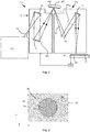
- Figure 1 shows a lithographic system comprising a radiation source SO and a lithographic apparatus LA.
- the radiation source SO is configured to generate an EUV radiation beam B and to supply the EUV radiation beam B to the lithographic apparatus LA.
- the lithographic apparatus LA comprises an illumination system IL, a support structure MT configured to support a patterning device MA (e.g., a mask), a projection system PS and a substrate table WT configured to support a substrate W.
- the support structure MT may be referred to as an object support and the substrate table WT may be referred to as an image support.
- the illumination system IL is configured to condition the EUV radiation beam B before the EUV radiation beam B is incident upon the patterning device MA.
- the illumination system IL may include a facetted field mirror device 10 and a facetted pupil mirror device 11.
- the faceted field mirror device 10 and faceted pupil mirror device 11 together provide the EUV radiation beam B with a desired cross-sectional shape and a desired intensity distribution.
- the illumination system IL may include other mirrors or devices in addition to, or instead of, the faceted field mirror device 10 and faceted pupil mirror device 11.
- the EUV radiation beam B interacts with the patterning device MA. As a result of this interaction, a patterned EUV radiation beam B' is generated.
- the projection system PS is configured to project the patterned EUV radiation beam B' onto the substrate W.
- the projection system PS may comprise a plurality of mirrors 13, 14 which are configured to project the patterned EUV radiation beam B' onto the substrate W held by the substrate table WT.
- the projection system PS may apply a reduction factor to the patterned EUV radiation beam B', thus forming an image with features that are smaller than corresponding features on the patterning device MA. For example, a reduction factor of 4 or 8 may be applied.
- the projection system PS is illustrated as having only two mirrors 13, 14 in Figure 1 , the projection system PS may include a different number of mirrors (e.g. six or eight mirrors).
- the substrate W may include previously formed patterns. Where this is the case, the lithographic apparatus LA aligns the image, formed by the patterned EUV radiation beam B', with a pattern previously formed on the substrate W.
- a relative vacuum i.e. a small amount of gas (e.g. hydrogen) at a pressure well below atmospheric pressure, may be provided in the radiation source SO, in the illumination system IL, and/or in the projection system PS.
- gas e.g. hydrogen
- the radiation source SO may be a laser produced plasma (LPP) source, a discharge produced plasma (DPP) source, a free electron laser (FEL) or any other radiation source that is capable of generating EUV radiation.
- LPP laser produced plasma
- DPP discharge produced plasma
- FEL free electron laser
- the lithographic apparatus may, for example, be used in a scan mode, wherein the support structure (e.g. mask table) MT and the substrate table WT are scanned synchronously while a pattern imparted to the radiation beam is projected onto a substrate W (i.e. a dynamic exposure).
- the velocity and direction of the substrate table WT relative to the support structure (e.g. mask table) MT may be determined by the demagnification and image reversal characteristics of the projection system PS.
- the patterned radiation beam that is incident upon the substrate W may comprise a band of radiation.
- the band of radiation may be referred to as an exposure slit.
- the movement of the substrate table WT and the support structure MT may be such that the exposure slit travels over an exposure field of the substrate W.
- a lithographic apparatus may be used to expose portions of a substrate W in order to form a pattern in the substrate W.
- one or more properties of the lithographic apparatus LA may be measured. Such properties may be measured on a regular basis, for example before and/or after exposure of each substrate W, or may be measured more infrequently, for example, as part of a calibration process. Examples of properties of the lithographic apparatus LA which may be measured include a relative alignment of components of the lithographic apparatus LA and/or an aberration of components of the lithographic apparatus.
- measurements may be made in order to determine the relative alignment of the support structure MT for supporting a patterning device MA and the substrate table WT for supporting a substrate W. Determining the relative alignment of the support structure MT and the substrate table WT assists in projecting a patterned radiation beam onto a desired portion of a substrate W. This may be particularly important when projecting patterned radiation onto a substrate W which includes portions which have already been exposed to radiation, so as to improve alignment of the patterned radiation with the previously exposed regions.
- optical aberration is a departure of the performance of an optical system from paraxial optics and may result in blurring or distortion of the pattern which is exposed at the substrate W.
- Aberrations of the projection system PS may be adjusted for and/or accounted for so as to increase the accuracy with which a desired pattern is formed on a substrate W.
- the projection system PS may be considered to be, or to form part of, an optical system for forming an image of the patterning device MA on the substrate W.
- the pattering device MA may be considered to be disposed in an object plane of the projection system PS and the substrate W may be considered to be disposed in an image plane of the projection system PS.
- the object plane of the projection system PS (where the patterning device MA is disposed), the image plane of the projection system PS (where the substrate W is disposed) and any planes conjugate thereto may be referred to as field planes of the lithographic apparatus. It will be appreciated that within an optical system (e.g. a lithographic apparatus) two planes are conjugate if each point within the first plane P is imaged onto a point in the second plane P'.
- the lithographic apparatus LA comprises optics with optical power (i.e. focusing and/or diverging optics) in order to form an image in the image plane of an object in the object plane.
- optics with optical power i.e. focusing and/or diverging optics
- a pupil plane which is a Fourier transform plane of a preceding field plane and a successive field plane.
- the distribution of the Electric field within each such pupil plane is related to a Fourier transform of an object disposed in a preceding field plane. It will be appreciated that the quality of such a pupil plane will depend on the optical design of the system and that such a pupil plane may even be curved.
- the projection system may comprise one or more intermediate field planes between the object plane and the image plane and there will be a pupil plane between each pair of field planes.
- the illumination system pupil plane and the projection system pupil plane are mutually conjugate planes.
- the projection system pupil plane PP PS may be referred to as the exit pupil of the projection system PS of the lithographic apparatus LA. This is the image of a physical stop or aperture (located within the projection system PL) on the image side of the projection system PL (i.e. the wafer side).
- the illuminator pupil plane PP IL may be referred to as the exit pupil of the illuminator IL.
- the illumination system pupil plane PP IL and the projection system pupil plane PP PS are shown schematically in Figure 1 . Note that the illumination system pupil plane PP IL coincides with the facetted pupil mirror device 11.
- each point in a field plane maps onto the entire successive pupil plane and vice versa.
- each field point in either the object plane or the image plane
- Each angle corresponds to a different point in the pupil plane. Therefore, a plurality of parallel rays of radiation at a field plane map onto a single point in a successive (or preceding) pupil plane.
- each point in the projection system pupil plane PP PS is conjugate to a point in the illuminator pupil plane PP IL
- diffraction from an object in the object plane will, in general, cause radiation from a given point in the illuminator pupil plane PP IL to map into a plurality of points in the projection system pupil plane PP PS .
- the zeroth order diffraction beam for a given point in the illuminator pupil plane PP IL will be imaged onto a conjugate point in the projection system pupil plane PP PS .
- Higher order diffraction beams will be imaged onto different parts of the projection system pupil plane PP PS or may fall outside of the numerical aperture of the projection system PS such that they do not contribute to the image formed in the image plane.
- the intensity (or, equivalently, the electric field strength) distribution of radiation in the illuminator pupil plane PP IL may be referred to as the illumination mode, pupil fill, pupil shape or pupil and characterizes the angular distribution of the light cone at the reticle level (i.e. in the object plane).
- the intensity (or, equivalently, the electric field strength) distribution of radiation in the projection system pupil plane PP PS characterizes the angular distribution of the light cone at the wafer level (i.e. in the image plane).
- the illuminator IL may alter the intensity distribution of the beam in the illuminator pupil plane PP IL .
- the illuminator may be arranged to limit the radial extent of the radiation beam such that the intensity distribution is non-zero within an annular region in the illuminator pupil plane PP IL .
- the illuminator IL may also be operable to limit the distribution of the beam in the illuminator pupil plane PP IL such that the intensity distribution is non-zero in a plurality of equally spaced sectors in the illuminator pupil plane PP IL .
- the intensity distribution of the radiation beam in a pupil plane of the illuminator IL may be referred to as an illumination mode.
- the illuminator IL is operable to control the spatial and the angular distribution of the radiation in the object plane. This is achieved via the facetted field mirror device 10 and the facetted pupil mirror device 11, each of which comprises a plurality of independently movable mirror elements. Generally, at least the outer and/or inner radial extent (commonly referred to as ⁇ -outer and ⁇ -inner, respectively) of the intensity distribution in the illuminator pupil plane PP IL can be adjusted.
- the illuminator IL may also be operable to vary the number, and angular extent, of sectors in the illuminator pupil plane PP IL wherein the intensity distribution is non-zero. By adjusting the intensity distribution of the beam in illuminator pupil plane PP IL of the illuminator IL, different illumination modes may be achieved.
- the illumination system IL and the projection system PS are used to form an image of an object level patterning device MA on an image level substrate W (e.g. a resist coated silicon wafer).
- an image level substrate W e.g. a resist coated silicon wafer.
- image quality can be significantly dependent on the angular intensity distribution of radiation that illuminates the patterning device MA.
- the illumination mode it may be desirable for the illumination mode to use a localized illumination mode. For example, it may be desirable to use a multipole (e.g.
- dipole or quadrupole illumination mode wherein in the pupil plane of the illumination system only a finite number (e.g. two or four) of discrete pole regions receive radiation. It is therefore desirable to have accurate control over the angular intensity distribution of radiation and for this purpose it is desirable to be able to measure the angular intensity distribution of radiation (for example to confirm that a desired angular intensity distribution of radiation has been achieved).
- a conjugate portion of the pupil at object level can contribute to imaging due to diffraction at the patterning device MA. It is therefore useful to determine the entire pupil at object level (including those parts that are conjugate to the obscuration).
- Embodiments of the present invention relate to new methods and apparatus for determining the angular intensity distribution of radiation at an object plane of an optical system (for example the plane of the patterning device MA in lithographic apparatus LA).
- these methods and apparatus allow this determination via a measurement at image plane level (i.e. in the plane of the substrate W), even in situations where there is an obscuration of the pupil plane within the optical system (i.e. in the projection system pupil plane PP PS ), as now discussed.
- Embodiments of the present invention use a diffraction grating 17 disposed in the object plane.
- the diffraction grating 17 is of the form of a reflective marker 17 (as schematically shown in Figure 1 ) with radiation.
- the reflective marker 17 forms part of a patterning device MA.
- One or more markers 17 may be provided on patterning devices MA used to perform lithographic exposures.
- a marker 17 may be positioned outside of a patterned region of the patterning device MA, which is illuminated with radiation during a lithographic exposure but may be moved into the path of the radiation during a measurement of the angular distribution of radiation at the object plane.
- one or more markers 17 may additionally or alternatively be provided on, and supported by, the support structure MT.
- a dedicated piece of hardware often referred to as a fiducial, may be provided on the support structure MT.
- a fiducial may include one or more markers.
- a fiducial is considered to be an example of a patterning device.
- a patterning device MA specifically designed for measuring one or more properties of the lithographic apparatus LA may be placed on the support structure MT in order to perform a measurement process.
- the patterning device MA may include one or more markers 17 for illumination as part of a measurement process.
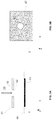
- the diffraction grating 30 is provided on a circular region 31 in the object plane that is surrounded by a radiation blocking region 32 that substantially blocks radiation received by it from entering the projection system PS.
- the diffraction grating comprises alternating reflective portions 33 and radiation absorbing portions 34 (which may be formed from the same material as radiation blocking region 32). That is, the diffraction grating 30 is provided on a reflective pinhole.
- the pinhole is circular and may have a diameter of the order of 50 ⁇ m.
- this allows the pupil at a particular field point (in the object plane) to be sampled. This may be advantageous since the pupil may be field dependent (in particular towards the edge of the field).
- such a reflective marker may be formed from a reflective substrate (for example a multi-layer stack or Bragg mirror) which provides the radiation reflecting portions.
- the radiation absorbing portions are formed by a depositing a radiation absorbing material onto the underlying reflective substrate.
- Embodiments of the present invention also use a sensor 19 (as shown schematically in Figure 1 ) on the substrate table WT, which is operable to form an image of the projection system pupil plane PP PS in a sensor plane to and determine a spatial intensity distribution of radiation in that sensor plane.
- the sensor apparatus 19 may, for example, be provided on the substrate table WT as shown in Figure 1 .
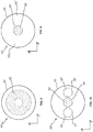
- FIG. 3A and 3B An embodiment 40 of the sensor 19 is shown in Figures 3A and 3B .
- the sensor 40 shown in Figures 3A and 3B comprises a membrane 41 having an aperture 42, the membrane 42 being disposed in an image plane of the projection system PS.
- the sensor further comprises a radiation sensor 43 disposed in a sensor plane 44 on an opposite side of the membrane 41 to the projection system PS. At least some of the radiation 25 which is output from the projection system PS passes through the aperture 42 and is incident on the radiation sensor 43 so as to form the image of the projection system pupil plane PP PS . That is, the image formation is achieved in a similar manner to a pinhole camera.
- the aperture 42 may be circular and may have a diameter of the order of 50 ⁇ m.
- the radiation sensor 43 is operable to determine a spatial intensity distribution of radiation which is incident on the radiation detector 43 in the sensor plane 44.
- the radiation detector 43 may, for example, comprise an array of individual detector elements.
- the radiation detector 43 may comprise a CCD or CMOS array.
- the support structure MT may be positioned such that the marker 17 is illuminated with radiation from the illumination system IL.
- the substrate table WT may be positioned such that radiation reflected from the marker is projected by the projection system PS onto the sensor apparatus 19.
- the support structure MT may be positioned such that the marker 17 on the patterning device MA is illuminated with radiation.
- the substrate table WT may be positioned such that radiation which is reflected from the marker 17 is projected, by the projection system PS, onto the sensor apparatus 19.
- the sensor apparatus 19 is in communication with a controller CN.
- the controller CN comprises a processor that is operable to determine at least a part of the angular intensity distribution of the radiation beam at the object plane from the determined spatial intensity distribution of radiation 25 in the sensor plane 44.
- a plurality of markers 17 and/or sensor apparatuses 19 may be provided and properties of the lithographic apparatus LA may be measured at a plurality of different field points (i.e. locations in a field or object plane of the projection system PS).
- the controller CN may be further configured to control one or more components of the illumination system IL of the lithographic apparatus LA.
- the controller CN may control a configuration of the facetted field mirror device 10 and/or the facetted pupil mirror device 11 so as to achieve a desired illumination mode.
- the projection system PS of a lithographic apparatus LA has an optical transfer function which may be non-uniform, which can affect the pattern which is imaged on the substrate W.
- optical transfer function which may be non-uniform, which can affect the pattern which is imaged on the substrate W.
- unpolarized radiation such effects can be fairly well described by two scalar maps, which describe the transmission (apodization) and relative phase (aberration) of radiation exiting the projection system PS as a function of position in a pupil plane thereof.
- it is desirable to determine such aberrations and transmission variations in addition to determining the angular distribution of radiation at reticle level.
- the sensor apparatus 19 can also be used for such measurements since it is disposed at wafer level on the substrate table WT.
- the membrane 41 with the aperture 42 can be replaced by a membrane that is of the form of a transmissive diffraction grating (for example of the form of a checkerboard).
- a membrane that is of the form of a transmissive diffraction grating for example of the form of a checkerboard.
- the apparatus and methods according to embodiments of the present invention are particularly suitable for measuring the pupil at object plane level in situations where there is an obscuration of the projection system pupil plane PP PS .
- these diffraction beams will be copies of the illumination system pupil plane PP IL with which the grating 17 was illuminated. It will be appreciated that, for each non-zeroth order diffraction beam, each such copy will be shifted in the pupil plane projection system pupil plane PP PS relative to the zeroth order diffraction beam (which corresponds to the pupil with which the grating 17 was illuminated).
- the amount by which these non-zeroth order diffraction beams are shifted is dependent on the pitch of the diffraction grating 17 and the wavelength of the radiation. It will be further appreciated that each such copy will be weighted by a grating efficiency for that diffraction order (which, in turn, is dependent on the geometry of the grating 17).
- Methods according to embodiments of the present invention produce shifted copies of the illumination system pupil plane PP IL in the projection system pupil plane PP PS .
- This can allow parts of the illumination system pupil plane PP IL which correspond to an obscuration of the projection system pupil plane PP PS to be shifted to a region of the projection system pupil plane PP PS which does not overlap with the obscuration.
- these parts of the object level pupil can be measured at image level.
- the projection system PS may have, for example, a central obscuration in the projection system pupil plane PP PS . That is, there may be an absence of radiation in a central portion of the cone of radiation that is projected onto the substrate W. Such a situation may occur in high numerical aperture EUV lithographic systems.
- the last mirror in the projection system PS (which is typically a concave, near-normal-incidence multi-layer stack mirror) of such a system is typically large and disposed above the substrate W.
- the radiation In order to deliver radiation to this mirror, typically the radiation must be delivered through a central aperture in this last mirror and reflected from a penultimate mirror that generally fills the last mirror with EUV radiation. The presence of the central aperture results in a central obscuration.
- FIG 4 is a schematic illustration of a conventional illumination mode 50 in the illumination system pupil plane PP IL that it may be desired to measure. With this illumination mode 50, only a central portion 51 of the illumination system pupil plane PP IL receives radiation whereas an outer portion 52 of the illumination system pupil plane PP IL does not. Also shown is a circle 53 which represents the numerical aperture of the projection system PS.
- Figure 5 is a schematic representation of the projection system pupil plane PP PS for a projection system PS having a central obscuration 54, representing a central portion of the projection system pupil plane PP PS which does not receive radiation. Also shown is a circle 53 which represents the numerical aperture of the projection system PS.
- Figure 6 is a schematic representation of the intensity of radiation in the projection system pupil plane PP PS of Figure 5 when a diffraction grating 17 is illuminated by the illumination mode 50 shown in Figure 4 .
- the resultant diffraction will, in general, cause radiation from a given point in the illuminator pupil plane PP IL to map into a plurality of points in the projection system pupil plane PP PS .
- the zeroth order diffraction beam for the illumination mode 50 maps onto a conjugate region 55 of the projection system pupil plane PP PS . This conjugate region 55 of the projection system pupil plane PP PS overlaps with the central obscuration 54.
- Higher order diffraction beams from the diffraction gratin 17 map onto different parts of the projection system pupil plane PP PS or may fall outside of the numerical aperture of the projection system PS such that they do not contribute to the image formed in the image plane.
- a region 56 of the projection system pupil plane PP PS which receives radiation from a +1 st order diffraction beam
- a region 57 of the projection system pupil plane PP PS which receives radiation from a -1 st order diffraction beam.
- each of these regions 56, 57 includes a region 58, 59 respectively which receives radiation from a part of the illumination mode 50 that is conjugate to the central obscuration 54.
- methods according to embodiments of the present invention produce shifted copies 56, 57 of the object level pupil or illumination mode 50 in the projection system pupil plane PP PS .
- This can allow parts of the object level pupil which correspond to (or are conjugate with) an obscuration 54 of the projection system pupil plane PP PS to be shifted to regions 58, 59 of the projection system pupil plane PP PS which do not overlap with the obscuration 54.
- these parts of the object level pupil 50 can be measured at image level.
- This embodiment uses two separate measurements which are then combined to determine the object level pupil or illumination mode 50. Although in the following description for clarity these will be referred to as a first measurement and a second measurement, it will be appreciated that the two measurements can be performed in any order.
- the illumination system IL is used to project the radiation beam B into an object that samples at least a part of the radiation such at least that part of the radiation is received by the projection system PS with substantially the same angular distribution.
- an object 60 is shown in Figure 7 , wherein the object 60 is of the form of a reflective pinhole.
- the object 60 comprises a circular region 61 of reflective material in the object plane that is surrounded by a radiation blocking region 32 that substantially blocks radiation received by it from entering the projection system PS.
- the circular region 61 and may have a diameter of the order of 50 ⁇ m.
- Figure 8 is a schematic representation of the intensity of radiation in the projection system pupil plane PP PS of Figure 5 when the object 60 shown in Figure 7 is illuminated by the illumination mode 50 shown in Figure 4 .
- a diffraction grating 17 is used, as described above, such that the parts of the illumination mode 50 that are conjugate to the obscuration 54 are mapped onto parts of the projection system pupil plane PP PS outside of the obscuration 54. These parts of the illumination mode 50 are therefore sampled by the sensor apparatus 19 and can be determined during this second measurement.
- a part of the angular distribution or illumination mode 50 to be measured is used during this second measurement using the diffraction grating 17.
- the only a part of the angular distribution to be measured which substantially corresponds to, or is substantially conjugate to, the obscuration 54 is used.
- a modified illumination mode 50' may be used.
- the modified illumination mode 50' comprises a smaller central portion 51' of the illumination system pupil plane PP IL which receives radiation and a larger outer portion 52' of the illumination system pupil plane PP IL which does not. It will be appreciated that the intensity distribution within the central portion 51' is the same as that of the corresponding or conjugate portion of the central portion 51 of illumination mode 50 shown in Figure 4 . Also shown is a circle 53 which represents the numerical aperture of the projection system PS and a circle 63 which represents the obscuration 54. It will be appreciated that the central portion 51' of the modified illumination mode 50' shown in Figure 9 preferably includes the entire circle 63 which represents the obscuration 54 and may also contain a little more of the central portion 51 of illumination mode 50 shown in Figure 4 .
- Figure 10 is a schematic representation of the intensity of radiation in the projection system pupil plane PP PS of Figure 5 when a diffraction grating 17 is illuminated by the modified illumination mode 50' shown in Figure 9 .
- Figure 10 shows: a region 55' which is conjugate to the modified illumination mode 50' and two regions 56', 57' of the projection system pupil plane PP PS which receive radiation from the +1 st order diffraction beam and the -1 st order diffraction beam respectively. Also shown are regions 58', 59' within each of these regions 56', 57' which receive radiation from a part of the modified illumination mode 50' that is conjugate to the central obscuration 54.
- the overlap between adjacent diffraction orders can be reduced or even eliminated.
- both of the regions 58', 59' which receive radiation from a part of the modified illumination mode 50' that is conjugate to the central obscuration 54 can be used to directly determine the part of the illumination mode 50 that is conjugate to the obscuration 50 and an average of these two determinations can be found.
- the modified illumination mode 50' (which is used for the second measurement) may and may also contain a little more of the central portion 51 of illumination mode 50 shown in Figure 4 (see Figure 9 ). This ensures that there will be some overlap between the first and second measurements (the outer part of the pupil measured without diffraction and the inner part of the pupil measured with diffraction).
- the intensities of the two separate measurements can be matched because certain parts of the pupil will be measured in both measurements.
- the pitch p of the grating 17 is such that an angular separation of adjacent diffraction beams is greater than half an angular extent of the obscuration 54 of the projection system PS.
- first order diffraction beams generated by the diffraction grating 17 will shift in the projection system pupil plane PP PS relative to the zeroth order diffraction beam such that at least half of the portion of those diffraction beams which corresponds to, or is conjugate to, the obscuration 54 no longer overlaps with the obscuration 54 of the projection system PS.
- the ⁇ 1 st order diffraction beams will each be shifted in opposite directions (by at least half of the extent of the obscuration 54 of the projection system PS), potentially allowing both halves of the region of the object level pupil that corresponds to the obscuration 54 of the projection system PS to be determined (from the ⁇ 1 st order diffraction beams respectively).
- the pitch p of the grating 17 is such that an angular separation of adjacent diffraction beams is greater than the entire angular extent of the obscuration 54 of the projection system PS. This allows the region of the object level pupil that corresponds to the obscuration 54 of the projection system PS to be determined from either one of the ⁇ 1 st order diffraction beams (or a combination of these, as discussed above).
- the pitch p of the grating 17 is such that an angular separation of adjacent diffraction beams is greater than an angular extent of the radiation that is projected onto the diffraction grating 17 in the object plane. That is, the pitch p of the grating 17 is sufficiently large (bearing in mind the angular extent of the modified illumination mode 50') that adjacent order diffraction beams generated by the diffraction grating 17 will not overlap in the projection system pupil plane PP PS .
- determining at least a part of the angular intensity distribution of radiation B at the object plane from the determined spatial intensity distribution of radiation 25 in the sensor plane 44 may comprise: associating at least one region of the spatial intensity distribution of radiation 25 in the sensor plane 44 with a weighted sum of a plurality of regions in the illumination system pupil plane PP IL , the weights of said weighted sum being dependent on grating efficiencies of the grating 17.
- Each such region of the spatial intensity distribution of radiation 25 in the sensor plane 44 may correspond to a single sensing element or pixel in an array of sensing elements.
- the radiation beam B when the radiation beam B is projected onto the diffraction grating 17 in the object plane so as to create at least one non-zeroth order diffraction beam which is at least partially received by the projection system PS substantially the entire angular distribution to be measured may be used. That is, an unmodified illumination mode 50 (as shown in Figure 4 ) may be used.
- the grating 17 may create a plurality of copies of the object level pupil 50, the copies being shifted relative to each other in a shearing direction of the grating 17. These diffraction beams may partially overlap (see, for example, Figure 6 ).
- At least some pixels in the sensor plane 44 may receive contributions from a plurality of different diffraction beams (and, therefore, from a plurality of different parts of the object level pupil 50 weighted by the corresponding grating efficiencies). It will be appreciated that this weighted sum may be an incoherent (intensity level) sum.
- the diffraction grating 17 may be arranged to suppress the zeroth order diffraction beam. It will be appreciated that such suppression of the zeroth order diffraction beam may be achieved using phase-shift mask techniques.
- the diffraction grating 17 may be of the form of an alternating phase-shift mask that is arranged such that alternate light transmitting portions (either transmissive or reflective) result in a 180° phase change for the zeroth order diffraction beam but not for non-zeroth order diffraction beams.
- a diffraction grating 30 of the type shown in Figure 2 may be formed from a reflective substrate (for example a multi-layer stack or Bragg mirror) which provides the radiation reflecting portions 33, onto which the radiation absorbing portions 32, 34 are deposited.
- alternate reflective portions 33 may be formed from different thicknesses of material so as to create a full optical path length difference for the zeroth order diffraction beam of ⁇ /2.
- the pitch p of the grating 17 is such that only the first order diffraction beams are at least partially received by the projection system PS. That is to say that the second order diffraction beams and higher order diffraction beams are not received by (i.e. fall outside the numerical aperture of) the projection system PS.
- the novel methods and apparatus according to the present invention are advantageous since they allow for measurement of parts of the illumination pupil (at reticle level) that correspond to an obscuration of the projection system PS via a wafer level measurement. It will be appreciated that such parts of the illumination pupil can be of relevance to the imaging of substrates W since, as explained above, diffraction from a patterning device MA can cause these parts of the illumination pupil to be projected onto the substrate W.
- lithographic processes for which it may be beneficial to use an illumination mode wherein a central portion of the illumination system pupil plane PP IL is populated by the radiation, as now discussed.
- Conducting contacts may be formed between structures of an integrated circuit that are formed in different layers of the integrated circuit. For example, it may be desirable to provide a conducting contact between a first structure in a first layer and a second structure in a second layer.
- Such structures may be formed by imaging a pattern of circular features in one or more layers that are intermediate the first and second layers in lithographic apparatus. These features may then be selectively etched away and the resultant contact hole can be filled with a conducting material.
- Imaging of a contact hole layer i.e. a pattern of circular features
- Imaging of a contact hole layer may be optimized by using an illumination mode wherein the intensity of radiation in the illumination system pupil plane PP IL is non-zero in a central portion and, in addition, in multiple discrete peripheral portions of the pupil plane PP IL .
- a large conventional illumination mode may be used for imaging dense lines at multiple pitches and multiple orientations, but not at the resolution limit (i.e. for features with sufficiently large pitches). It will be appreciated here that a large conventional illumination mode is one for which the intensity of radiation is uniform within a central circular portion of the illumination system pupil plane PP IL , the central circular portion comprising a large portion of the numerical aperture of the projection system PS (for example, as shown in Figure 4 ).
- an illumination mode where there is significant overlap between the regions of the illumination system pupil plane PP IL where the intensity of radiation is non-zero and an obscuration in the projection system PS can be beneficial. This is because this may ensure that the 0th order beam generated as the radiation is directed to a patterning device MA does not contribute significantly (or at all) to the imaging. In turn, this can be beneficial for the imaging because, for example, it can improve contrast and depth of focus for some structures (pitches), particularly when patterns having different pitches are imaged at the same time.
- the diffraction grating 17 may have other forms.
- the diffraction grating 17 may have any form.
- the diffraction grating 17 may be a two-dimensional diffraction grating.
- the diffraction grating will generate a two-dimensional array of diffraction beams (which may or may not partially overlap) and which are at least partially received by the projection system PS.
- the diffraction grating may have any orientation and any pitch (or pitches) as desired.
- lithographic apparatus in the manufacture of ICs, it should be understood that the lithographic apparatus described herein may have other applications. Possible other applications include the manufacture of integrated optical systems, guidance and detection patterns for magnetic domain memories, flat-panel displays, liquid-crystal displays (LCDs), thin-film magnetic heads, etc.
- Embodiments of the invention may form part of a mask inspection apparatus, a metrology apparatus, or any apparatus that measures or processes an object such as a wafer (or other substrate) or mask (or other patterning device). These apparatus may be generally referred to as lithographic tools. Such a lithographic tool may use vacuum conditions or ambient (non-vacuum) conditions.
Landscapes
- Physics & Mathematics (AREA)
- General Physics & Mathematics (AREA)
- Exposure And Positioning Against Photoresist Photosensitive Materials (AREA)
Abstract
A method for determining at least a part of an angular intensity distribution of radiation at an object plane of an optical system, which may be referred to as an object level pupil shape, is disclosed. The method comprises directing the radiation onto a diffraction grating in the object plane so as to create at least one non-zeroth order diffraction beam which is at least partially received by the optical system; forming an image of a pupil plane of the optical system in a sensor plane and determining a spatial intensity distribution of radiation in the sensor plane; and determining at least a part of the angular intensity distribution of radiation at the object plane from the determined spatial intensity distribution of radiation in the sensor plane. The method is advantageous since it allows reconstruction of the angular intensity distribution of radiation at an object plane of an optical system, from a measurement at image plane level, even in situations where there is an obscuration of the pupil plane within the optical system.
Description
- The present invention relates to a method and apparatus for determining a pupil shape, i.e. the angular intensity distribution of radiation at a field plane of an optical system (for example a lithographic apparatus). In particular, the present invention is concerned with determining such a pupil shape in an object plane (for example at reticle level) from a measurement in an image plane (for example at wafer level). The present invention has particular application for optical systems that have an obscuration such as, for example, high numerical aperture EUV lithographic systems.
- A lithographic apparatus is a machine constructed to apply a desired pattern onto a substrate. A lithographic apparatus can be used, for example, in the manufacture of integrated circuits (ICs). A lithographic apparatus may, for example, project a pattern at a patterning device (e.g., a mask) onto a layer of radiation-sensitive material (resist) provided on a substrate.
- To project a pattern on a substrate a lithographic apparatus may use electromagnetic radiation. The wavelength of this radiation determines the minimum size of features which can be formed on the substrate. A lithographic apparatus, which uses extreme ultraviolet (EUV) radiation, having a wavelength within the range 4-20 nm, for example 6.7 nm or 13.5 nm, may be used to form smaller features on a substrate than a lithographic apparatus which uses, for example, radiation with a wavelength of 193 nm.
- There is a constant desire in the field of lithography to form images on substrates with smaller dimensions and it will be appreciated that generally the image of the patterning device that is formed on the substrate is diffraction limited. Under these circumstances image quality can be significantly dependent on the angular intensity distribution of radiation that illuminates the patterning device (also referred to as the pupil, pupil shape or illumination mode). It is therefore desirable to have accurate control over the angular intensity distribution of radiation and for this purpose it is desirable to be able to measure the angular intensity distribution of radiation (for example to confirm that a desired angular intensity distribution of radiation has been achieved).
- It may be desirable to provide a method and apparatus for measuring an angular distribution of an illumination beam that addresses one or more problems present in prior art systems.
- According to a first aspect of the present invention there is provided a method for determining at least a part of an angular intensity distribution of radiation at an object plane of an optical system, the method comprising: directing the radiation onto a diffraction grating in the object plane so as to create at least one non-zeroth order diffraction beam which is at least partially received by the optical system; forming an image of a pupil plane of the optical system in a sensor plane and determining a spatial intensity distribution of radiation in the sensor plane; and determining at least a part of the angular intensity distribution of radiation at the object plane from the determined spatial intensity distribution of radiation in the sensor plane.
- The method according to the first aspect of the invention is advantageous since it allows reconstruction of the angular intensity distribution of radiation at an object plane of an optical system, from a measurement at image plane level, even in situations where there is an obscuration of the pupil plane within the optical system, as now discussed.
- The optical system may comprise the projection system of a lithographic apparatus. Such an apparatus can be used to form an image of a patterning device (also known as a reticle) on a substrate (for example a resist covered silicon wafer). It will be appreciated that for such embodiments, the object plane may coincide with a plane in which the patterning device is disposed and the image plane may coincide with a plane in which the substrate is disposed. The object plane of the projection system, the image plane of the projection system and any planes conjugate thereto may be referred to as field planes of the lithographic apparatus.
- There is a constant desire in the field of lithography to form images with smaller dimensions and it will be appreciated that generally the image of the patterning device that is formed on the substrate is diffraction limited. Under these circumstances image quality can be significantly dependent on the angular intensity distribution of radiation that illuminates the patterning device. It is therefore desirable to have accurate control over the angular intensity distribution of radiation and for this purpose it is desirable to be able to measure the angular intensity distribution of radiation (for example to confirm that a desired angular intensity distribution of radiation has been achieved).
- The intensity (or, equivalently, the electric field strength) distribution of radiation in the illumination pupil plane (also known as the pupil or pupil shape) characterizes the angular distribution of the light cone at the reticle level (i.e. in the object plane).
- Typically, the projection system of a lithographic apparatus has an optical transfer function which may be non-uniform, which can affect the pattern which is imaged on the substrate. For unpolarized radiation such effects can be fairly well described by two scalar maps, which describe the transmission (apodization) and relative phase (aberration) of radiation exiting the projection system as a function of position in a pupil plane thereof. Typically, it is also desirable to determine such aberrations and transmission variations. Advantageously, the method according to the first aspect of the invention avoids having to use two separate sensors (one in the object plane and one in the image plane) by allowing the angular intensity distribution of radiation at the object level of an optical system to be determined from a measurement at image plane level.
- Furthermore, the method according to the first aspect of the invention allows parts of the pupil at object plane level to be determined even in situations where there is an obscuration of the pupil plane within the optical system. This is because when the radiation is directed onto the diffraction grating in the object plane and one or more order diffraction beams are created, in the pupil plane of the projection system, these diffraction beams will be copies of the pupil with which the grating was illuminated. It will be appreciated that, for each non-zeroth order diffraction beam, each such copy will be shifted in the pupil plane relative to the zeroth order diffraction beam (which corresponds to the pupil with which the grating was illuminated). The amount by which these non-zeroth order diffraction beams are shifted is dependent on the pitch of the diffraction grating and the wavelength of the radiation. It will be appreciated that, in general, each non-zeroth order diffraction beam will be shifted by a different amount relative to the zeroth order diffraction beam in the pupil plane. In particular, in pupil plane coordinates that are normalized to the numerical aperture of the optical system, the shift of each non-zeroth order diffraction beam from the zeroth order diffraction beam in the pupil plane is given by (n·λ)/(p·NA), where n is the diffraction order, λ is the wavelength of the radiation, p is the pitch of the diffraction grating and NA is the numerical aperture of the optical system. It will be further appreciated that each such copy will be weighted by a grating efficiency for that diffraction order (which, in turn, is dependent on the geometry of the grating).
- The method according to the present invention therefore produces shifted copies of the object level pupil in the pupil plane of the projection system. This can allow parts of the object level pupil which correspond to an obscuration of the projection system pupil plane to be shifted to a region of the projection system pupil plane which does not overlap with the obscuration. As a result, these parts of the object level pupil can be measured at image level.
- The method may further comprise: directing the radiation onto an object that samples at least a part of the radiation such that at least that part of the radiation is received by the optical system with substantially the same angular distribution; forming an image of a pupil plane of the optical system in a sensor plane and determining a spatial intensity distribution of radiation in the sensor plane; and determining at least a part of the angular intensity distribution of radiation at the object plane from the determined spatial intensity distribution of radiation in the sensor plane.
- For such embodiments, the step of directing the radiation onto an object that samples at least a part of the radiation such that at least that part of the radiation is received by the optical system with substantially the same angular distribution can be used to determine parts of the object level pupil that do not correspond to an obscuration within the optical system. It will be appreciated that, separately, the step of directing the radiation onto a diffraction grating in the object plane so as to create at least one non-zeroth order diffraction beam which is at least partially received by the optical system can be used to determine parts of the object level pupil that do correspond to an obscuration within the optical system.
- It will be appreciated that for reflective systems, an object that samples at least a part of the radiation such at least that part of the radiation is received by the optical system with substantially the same angular distribution comprises a mirror that is arranged to provide specular reflection. It will be appreciated that for transmissive systems, an object that samples at least a part of the radiation such at least that part of the radiation is received by the optical system with substantially the same angular distribution comprises a transmissive portion that is arranged to transmit the radiation.
- When the radiation is directed onto the diffraction grating in the object plane so as to create at least one non-zeroth order diffraction beam which is at least partially received by the optical system it may be that only a part of the angular distribution to be measured is used.
- The only a part of the angular distribution to be measured may substantially correspond to a part of a pupil plane of the optical system that is obscured by the optical system.
- It will be appreciated that as used here, a part of the angular distribution substantially corresponding to a part of a pupil plane of the optical system that is obscured by the optical system may include that part of a pupil plane of the optical system that is obscured by the optical system and may optionally also include a bit more of the pupil plane.
- The pitch of the grating may be such that an angular separation of adjacent diffraction beams is greater than half an angular extent of an obscuration of the optical system.
- Advantageously, with such an arrangement first order diffraction beams generated by the diffraction grating will shift the region of the object level pupil such that at least half of them no longer overlap with the obscuration of the optical system. The ±1st order diffraction beams will each be shifted in opposite directions (by at least half of the extent of the obscuration of the optical system), potentially allowing both halves of the region of the object level pupil that corresponds to the obscuration of the optical system to be determined (from the ±1st order diffraction beams respectively).
- The pitch of the grating may be such that an angular separation of adjacent diffraction beams is greater than an angular extent of the radiation that is directed onto the diffraction grating in the object plane.
- Advantageously, with such an arrangement adjacent order diffraction beams generated by the diffraction grating will not overlap in the pupil plane of the optical system.
- Determining at least a part of the angular intensity distribution of radiation at the object plane from the determined spatial intensity distribution of radiation in the sensor plane may comprise: associating at least one region of the spatial intensity distribution of radiation in the sensor plane with a weighted sum of a plurality of regions in an object level pupil plane, the weights of said weighted sum of pixels being dependent on grating efficiencies of the grating.
- For example, in one embodiment, when the radiation is directed onto the diffraction grating in the object plane so as to create at least one non-zeroth order diffraction beam which is at least partially received by the optical system substantially the entire angular distribution to be measured may be used. The grating may create a plurality of copies of the object level pupil, the copies being shifted relative to each other in a shearing direction of the grating. These diffraction beams may partially overlap. Therefore, at least some pixels in the sensor plane may receive contributions from a plurality of different diffraction beams (and, therefore, from a plurality of different parts of the object level pupil weighted by the corresponding grating efficiencies). It will be appreciated that this weighted sum may be an incoherent (intensity level) sum.
- The pitch of the grating may be such that an angular separation of adjacent diffraction beams is greater than half an angular extent of an obscuration of the optical system.
- Forming the image of the pupil plane of the optical system in the sensor plane and determining a spatial intensity distribution of radiation in the sensor plane may comprise: projecting the radiation onto a membrane having an aperture, the membrane being disposed in an image plane of the optical system; and determining a spatial intensity distribution of radiation in a sensor plane on an opposite side of the membrane to the optical system.
- That is, the image formation is achieved in a similar manner to a pinhole camera. The aperture may be circular and may have a diameter of the order of 50 µm.
- The diffraction grating may be provided on a region in the object plane that is surrounded by a radiation blocking region that substantially blocks radiation received by it from entering the optical system.
- That is, the diffraction grating may be provided on a pinhole (either reflective or transmissive). The pinhole may be circular and may have a diameter of the order of 50 µm. Advantageously, this allows the pupil at a particular field point (in the object plane) to be sampled. This may be advantageous since the pupil may be field dependent (in particular towards the edge of the field).
- The object that samples at least a part of the radiation such at least that part of the radiation is received by the optical system with substantially the same angular distribution may be provided on a region in the object plane that is surrounded by a radiation blocking region that substantially blocks radiation received by it from entering the optical system.
- The diffraction grating may be arranged to suppress the zeroth order diffraction beam.
- It will be appreciated that such suppression of the zeroth order diffraction beam may be achieved using phase-shift mask techniques. For example, the diffraction grating may be of the form of an alternating phase-shift mask that is arranged such that alternate light transmitting portions (either transmissive or reflective) result in a 180° phase change for the zeroth order diffraction beam but not for non-zeroth order diffraction beams.
- Advantageously, this results in no zeroth order diffraction beam that may overlap with the non-zeroth order diffraction beams (for example the first order diffraction beams).
- The pitch of the grating may be such that only the first order diffraction beams are at least partially received by the optical system.
- The pitch of the grating may be such that second order diffraction beams and higher order diffraction beams are not received by the optical system.
- According to a second aspect of the present invention there is provided an apparatus comprising: an object support for supporting a patterning device in an object plane; an image support for supporting a substrate in an image plane; an illumination system operable to produce a radiation beam and irradiate the patterning device in the object plane so as to form a patterned radiation beam; a projection system operable to receive the patterned radiation beam and to form an image of the patterning device in the image plane; and a sensor, the sensor being operable to form an image of a pupil plane of the projection system in a sensor plane to and determine a spatial intensity distribution of radiation in the sensor plane; and a processor operable to determine at least a part of the angular intensity distribution of the radiation beam at the object plane from the determined spatial intensity distribution of radiation in the sensor plane; wherein the projection system has an obscuration such that an intensity of the patterned radiation beam in a part of the pupil plane of the projection system is substantially zero; and wherein the at least a part of the angular intensity distribution of the radiation beam that the processor is operable to determine includes a part of the angular intensity distribution of the radiation beam that corresponds to the obscuration of the projection system.
- The apparatus according to the second aspect of the invention is operable to carry out the method according to the first aspect of the invention. The apparatus according to the second aspect of the invention may comprise a lithographic apparatus.
- It will be appreciated that the patterning device may comprise a diffraction grating arranged to create at least one non-zeroth order diffraction beam which is at least partially received by the projection system.
- The sensor may be disposed on the image support. Alternatively, the sensor may be disposed on a separate component such as a fiducial. Such a fiducial may be supported by the image support or, alternatively the fiducial and the image support may both ne supported by a common supporting member.
- The apparatus according to the second aspect of the invention may be configured to perform the method of the first aspect of the invention.
- Embodiments of the invention will now be described, by way of example only, with reference to the accompanying schematic drawings, in which:
-
Figure 1 depicts a lithographic system comprising a lithographic apparatus and a radiation source; -
Figure 2 is a schematic representation of a diffraction grating that may be provided on the support structure of the lithographic system shown inFigure 1 and used as part of a method for determining at least a part of an angular intensity distribution of radiation at an object plane of the lithographic system; -
Figure 3A is a schematic cross-sectional representation of a sensor that may be provided on the substrate table of the lithographic system shown inFigure 1 and used as part of a method for determining at least a part of an angular intensity distribution of radiation at an object plane of the lithographic system; -
Figure 3B is a schematic top view of a membrane having an aperture that forms part of the sensor shown inFigure 3A ; -
Figure 4 is a schematic illustration of a conventional illumination mode in an illumination system pupil plane of the lithographic system shown inFigure 1 that it may be desired to measure; -
Figure 5 is a schematic representation of the projection system pupil plane for a lithographic apparatus projection system having a central obscuration; -
Figure 6 is a schematic representation of the intensity of radiation in the projection system pupil plane ofFigure 5 when a diffraction grating of the type shown inFigure 2 is illuminated by the illumination mode shown inFigure 4 ; -
Figure 7 is a schematic representation of an object that may be provided on the support structure of the lithographic system shown inFigure 1 and which samples at least a part of radiation received from an illumination system of the lithographic apparatus such at least that part of the radiation is received by the projection system of the lithographic apparatus with substantially the same angular distribution; -
Figure 8 is a schematic representation of the intensity of radiation in the projection system pupil plane ofFigure 5 when the object shown inFigure 7 is illuminated by the illumination mode shown inFigure 4 ; -
Figure 9 is a schematic illustration of a modified illumination mode in an illumination system pupil plane of the lithographic system shown inFigure 1 , the modified illumination mode comprising a portion of the illumination mode shown inFigure 4 ; and -
Figure 10 is a schematic representation of the intensity of radiation in the projection system pupil plane ofFigure 5 when a diffraction grating of the type shown inFigure 2 is illuminated by the modified illumination mode shown inFigure 9 . -
Figure 1 shows a lithographic system comprising a radiation source SO and a lithographic apparatus LA. The radiation source SO is configured to generate an EUV radiation beam B and to supply the EUV radiation beam B to the lithographic apparatus LA. The lithographic apparatus LA comprises an illumination system IL, a support structure MT configured to support a patterning device MA (e.g., a mask), a projection system PS and a substrate table WT configured to support a substrate W. The support structure MT may be referred to as an object support and the substrate table WT may be referred to as an image support. - The illumination system IL is configured to condition the EUV radiation beam B before the EUV radiation beam B is incident upon the patterning device MA. Thereto, the illumination system IL may include a facetted
field mirror device 10 and a facettedpupil mirror device 11. The facetedfield mirror device 10 and facetedpupil mirror device 11 together provide the EUV radiation beam B with a desired cross-sectional shape and a desired intensity distribution. The illumination system IL may include other mirrors or devices in addition to, or instead of, the facetedfield mirror device 10 and facetedpupil mirror device 11. - After being thus conditioned, the EUV radiation beam B interacts with the patterning device MA. As a result of this interaction, a patterned EUV radiation beam B' is generated. The projection system PS is configured to project the patterned EUV radiation beam B' onto the substrate W. For that purpose, the projection system PS may comprise a plurality of
mirrors mirrors Figure 1 , the projection system PS may include a different number of mirrors (e.g. six or eight mirrors). - The substrate W may include previously formed patterns. Where this is the case, the lithographic apparatus LA aligns the image, formed by the patterned EUV radiation beam B', with a pattern previously formed on the substrate W.
- A relative vacuum, i.e. a small amount of gas (e.g. hydrogen) at a pressure well below atmospheric pressure, may be provided in the radiation source SO, in the illumination system IL, and/or in the projection system PS.
- The radiation source SO may be a laser produced plasma (LPP) source, a discharge produced plasma (DPP) source, a free electron laser (FEL) or any other radiation source that is capable of generating EUV radiation.
- The lithographic apparatus may, for example, be used in a scan mode, wherein the support structure (e.g. mask table) MT and the substrate table WT are scanned synchronously while a pattern imparted to the radiation beam is projected onto a substrate W (i.e. a dynamic exposure). The velocity and direction of the substrate table WT relative to the support structure (e.g. mask table) MT may be determined by the demagnification and image reversal characteristics of the projection system PS. The patterned radiation beam that is incident upon the substrate W may comprise a band of radiation. The band of radiation may be referred to as an exposure slit. During a scanning exposure, the movement of the substrate table WT and the support structure MT may be such that the exposure slit travels over an exposure field of the substrate W.
- As has been described above, a lithographic apparatus may be used to expose portions of a substrate W in order to form a pattern in the substrate W. In order to improve the accuracy with which a desired pattern is transferred to a substrate W one or more properties of the lithographic apparatus LA may be measured. Such properties may be measured on a regular basis, for example before and/or after exposure of each substrate W, or may be measured more infrequently, for example, as part of a calibration process. Examples of properties of the lithographic apparatus LA which may be measured include a relative alignment of components of the lithographic apparatus LA and/or an aberration of components of the lithographic apparatus. For example, measurements may be made in order to determine the relative alignment of the support structure MT for supporting a patterning device MA and the substrate table WT for supporting a substrate W. Determining the relative alignment of the support structure MT and the substrate table WT assists in projecting a patterned radiation beam onto a desired portion of a substrate W. This may be particularly important when projecting patterned radiation onto a substrate W which includes portions which have already been exposed to radiation, so as to improve alignment of the patterned radiation with the previously exposed regions.
- Additionally or alternatively measurements may be made in order to determine optical aberrations of the projection system PS. An optical aberration is a departure of the performance of an optical system from paraxial optics and may result in blurring or distortion of the pattern which is exposed at the substrate W. Aberrations of the projection system PS may be adjusted for and/or accounted for so as to increase the accuracy with which a desired pattern is formed on a substrate W.
- The projection system PS may be considered to be, or to form part of, an optical system for forming an image of the patterning device MA on the substrate W. The pattering device MA may be considered to be disposed in an object plane of the projection system PS and the substrate W may be considered to be disposed in an image plane of the projection system PS. In the context of such a lithographic apparatus, the object plane of the projection system PS (where the patterning device MA is disposed), the image plane of the projection system PS (where the substrate W is disposed) and any planes conjugate thereto may be referred to as field planes of the lithographic apparatus. It will be appreciated that within an optical system (e.g. a lithographic apparatus) two planes are conjugate if each point within the first plane P is imaged onto a point in the second plane P'.
- It will be appreciated that the lithographic apparatus LA comprises optics with optical power (i.e. focusing and/or diverging optics) in order to form an image in the image plane of an object in the object plane. Within such an optical system, between each pair of field planes it is possible to define a pupil plane which is a Fourier transform plane of a preceding field plane and a successive field plane. The distribution of the Electric field within each such pupil plane is related to a Fourier transform of an object disposed in a preceding field plane. It will be appreciated that the quality of such a pupil plane will depend on the optical design of the system and that such a pupil plane may even be curved.
- It will also be appreciated that there may be more than one pupil plane disposed in the optical path between the object plane and the image plane. For example, in some embodiments, the projection system may comprise one or more intermediate field planes between the object plane and the image plane and there will be a pupil plane between each pair of field planes.
- It is useful to consider two pupil planes: an illumination system pupil plane PPIL and a projection system pupil plane PPPS. The illumination system pupil plane and the projection system pupil plane (and any other pupil planes) are mutually conjugate planes. The projection system pupil plane PPPS may be referred to as the exit pupil of the projection system PS of the lithographic apparatus LA. This is the image of a physical stop or aperture (located within the projection system PL) on the image side of the projection system PL (i.e. the wafer side). Similarly, the illuminator pupil plane PPIL may be referred to as the exit pupil of the illuminator IL.
- The illumination system pupil plane PPIL and the projection system pupil plane PPPS are shown schematically in
Figure 1 . Note that the illumination system pupil plane PPIL coincides with the facettedpupil mirror device 11. - Note that each point in a field plane maps onto the entire successive pupil plane and vice versa. In particular, each field point (in either the object plane or the image plane) receives radiation at a range of angles. Each angle corresponds to a different point in the pupil plane. Therefore, a plurality of parallel rays of radiation at a field plane map onto a single point in a successive (or preceding) pupil plane.
- Note that although each point in the projection system pupil plane PPPS is conjugate to a point in the illuminator pupil plane PPIL, diffraction from an object in the object plane will, in general, cause radiation from a given point in the illuminator pupil plane PPIL to map into a plurality of points in the projection system pupil plane PPPS. The zeroth order diffraction beam for a given point in the illuminator pupil plane PPIL will be imaged onto a conjugate point in the projection system pupil plane PPPS. Higher order diffraction beams will be imaged onto different parts of the projection system pupil plane PPPS or may fall outside of the numerical aperture of the projection system PS such that they do not contribute to the image formed in the image plane.
- The intensity (or, equivalently, the electric field strength) distribution of radiation in the illuminator pupil plane PPIL may be referred to as the illumination mode, pupil fill, pupil shape or pupil and characterizes the angular distribution of the light cone at the reticle level (i.e. in the object plane). Similarly, the intensity (or, equivalently, the electric field strength) distribution of radiation in the projection system pupil plane PPPS characterizes the angular distribution of the light cone at the wafer level (i.e. in the image plane).
- As explained above, the illuminator IL may alter the intensity distribution of the beam in the illuminator pupil plane PPIL. The illuminator may be arranged to limit the radial extent of the radiation beam such that the intensity distribution is non-zero within an annular region in the illuminator pupil plane PPIL. Additionally or alternatively, the illuminator IL may also be operable to limit the distribution of the beam in the illuminator pupil plane PPIL such that the intensity distribution is non-zero in a plurality of equally spaced sectors in the illuminator pupil plane PPIL. The intensity distribution of the radiation beam in a pupil plane of the illuminator IL may be referred to as an illumination mode.
- The illuminator IL is operable to control the spatial and the angular distribution of the radiation in the object plane. This is achieved via the facetted
field mirror device 10 and the facettedpupil mirror device 11, each of which comprises a plurality of independently movable mirror elements. Generally, at least the outer and/or inner radial extent (commonly referred to as σ-outer and σ-inner, respectively) of the intensity distribution in the illuminator pupil plane PPIL can be adjusted. By convention, the radial coordinate σ of a point in the illuminator pupil plane PPIL or the projection system pupil plane PPPS is typically normalised by the numerical aperture NA of the projections system PS (such that a circle of radius σ=1 corresponds to the region of the pupil plane which can physically be captured by the projection system PL and imaged onto the image plane IP). The illuminator IL may also be operable to vary the number, and angular extent, of sectors in the illuminator pupil plane PPIL wherein the intensity distribution is non-zero. By adjusting the intensity distribution of the beam in illuminator pupil plane PPIL of the illuminator IL, different illumination modes may be achieved. - During exposure of a substrate W the illumination system IL and the projection system PS are used to form an image of an object level patterning device MA on an image level substrate W (e.g. a resist coated silicon wafer). There is a constant desire in the field of lithography to form images with smaller dimensions and it will be appreciated that generally the image of the patterning device MA that is formed on the substrate W is diffraction limited. Under these circumstances image quality can be significantly dependent on the angular intensity distribution of radiation that illuminates the patterning device MA. During such an exposure, it may be desirable for the illumination mode to use a localized illumination mode. For example, it may be desirable to use a multipole (e.g. dipole or quadrupole) illumination mode, wherein in the pupil plane of the illumination system only a finite number (e.g. two or four) of discrete pole regions receive radiation. It is therefore desirable to have accurate control over the angular intensity distribution of radiation and for this purpose it is desirable to be able to measure the angular intensity distribution of radiation (for example to confirm that a desired angular intensity distribution of radiation has been achieved).
- Furthermore, as explained above, even for optical systems that have an obscuration at image level (for example in a projection system pupil plane PPPS) a conjugate portion of the pupil at object level can contribute to imaging due to diffraction at the patterning device MA. It is therefore useful to determine the entire pupil at object level (including those parts that are conjugate to the obscuration).
- Embodiments of the present invention relate to new methods and apparatus for determining the angular intensity distribution of radiation at an object plane of an optical system (for example the plane of the patterning device MA in lithographic apparatus LA). In particular, these methods and apparatus allow this determination via a measurement at image plane level (i.e. in the plane of the substrate W), even in situations where there is an obscuration of the pupil plane within the optical system (i.e. in the projection system pupil plane PPPS), as now discussed.
- Embodiments of the present invention use a
diffraction grating 17 disposed in the object plane. Thediffraction grating 17 is of the form of a reflective marker 17 (as schematically shown inFigure 1 ) with radiation. - In the embodiment which is shown in
Figure 1 , thereflective marker 17 forms part of a patterning device MA. One ormore markers 17 may be provided on patterning devices MA used to perform lithographic exposures. Amarker 17 may be positioned outside of a patterned region of the patterning device MA, which is illuminated with radiation during a lithographic exposure but may be moved into the path of the radiation during a measurement of the angular distribution of radiation at the object plane. In some embodiments, one ormore markers 17 may additionally or alternatively be provided on, and supported by, the support structure MT. For example, a dedicated piece of hardware, often referred to as a fiducial, may be provided on the support structure MT. A fiducial may include one or more markers. For the purposes of this description a fiducial is considered to be an example of a patterning device. In some embodiments, a patterning device MA specifically designed for measuring one or more properties of the lithographic apparatus LA may be placed on the support structure MT in order to perform a measurement process. The patterning device MA may include one ormore markers 17 for illumination as part of a measurement process. - An
embodiment 30 of thediffraction grating 17 is shown inFigure 2 . In this embodiment, thediffraction grating 30 is provided on acircular region 31 in the object plane that is surrounded by aradiation blocking region 32 that substantially blocks radiation received by it from entering the projection system PS. Within thecircular region 31, the diffraction grating comprises alternatingreflective portions 33 and radiation absorbing portions 34 (which may be formed from the same material as radiation blocking region 32). That is, thediffraction grating 30 is provided on a reflective pinhole. The pinhole is circular and may have a diameter of the order of 50 µm. Advantageously, this allows the pupil at a particular field point (in the object plane) to be sampled. This may be advantageous since the pupil may be field dependent (in particular towards the edge of the field). - It will be appreciated that such a reflective marker may be formed from a reflective substrate (for example a multi-layer stack or Bragg mirror) which provides the radiation reflecting portions. The radiation absorbing portions are formed by a depositing a radiation absorbing material onto the underlying reflective substrate.
- Embodiments of the present invention also use a sensor 19 (as shown schematically in
Figure 1 ) on the substrate table WT, which is operable to form an image of the projection system pupil plane PPPS in a sensor plane to and determine a spatial intensity distribution of radiation in that sensor plane. Thesensor apparatus 19 may, for example, be provided on the substrate table WT as shown inFigure 1 . - An embodiment 40 of the
sensor 19 is shown inFigures 3A and 3B . - The sensor 40 shown in
Figures 3A and 3B comprises amembrane 41 having anaperture 42, themembrane 42 being disposed in an image plane of the projection system PS. The sensor further comprises aradiation sensor 43 disposed in asensor plane 44 on an opposite side of themembrane 41 to the projection system PS. At least some of theradiation 25 which is output from the projection system PS passes through theaperture 42 and is incident on theradiation sensor 43 so as to form the image of the projection system pupil plane PPPS. That is, the image formation is achieved in a similar manner to a pinhole camera. Theaperture 42 may be circular and may have a diameter of the order of 50 µm. - The
radiation sensor 43 is operable to determine a spatial intensity distribution of radiation which is incident on theradiation detector 43 in thesensor plane 44. Theradiation detector 43 may, for example, comprise an array of individual detector elements. For example, theradiation detector 43 may comprise a CCD or CMOS array. - During a method for determining at least a part of an angular intensity distribution of radiation at the object plane of the projection system PS, the support structure MT may be positioned such that the
marker 17 is illuminated with radiation from the illumination system IL. The substrate table WT may be positioned such that radiation reflected from the marker is projected by the projection system PS onto thesensor apparatus 19. - In order to perform a measurement process, the support structure MT may be positioned such that the
marker 17 on the patterning device MA is illuminated with radiation. The substrate table WT may be positioned such that radiation which is reflected from themarker 17 is projected, by the projection system PS, onto thesensor apparatus 19. Thesensor apparatus 19 is in communication with a controller CN. The controller CN comprises a processor that is operable to determine at least a part of the angular intensity distribution of the radiation beam at the object plane from the determined spatial intensity distribution ofradiation 25 in thesensor plane 44. - In some embodiments a plurality of
markers 17 and/orsensor apparatuses 19 may be provided and properties of the lithographic apparatus LA may be measured at a plurality of different field points (i.e. locations in a field or object plane of the projection system PS). - The controller CN may be further configured to control one or more components of the illumination system IL of the lithographic apparatus LA. For example, the controller CN may control a configuration of the facetted
field mirror device 10 and/or the facettedpupil mirror device 11 so as to achieve a desired illumination mode. - Typically, the projection system PS of a lithographic apparatus LA has an optical transfer function which may be non-uniform, which can affect the pattern which is imaged on the substrate W. For unpolarized radiation such effects can be fairly well described by two scalar maps, which describe the transmission (apodization) and relative phase (aberration) of radiation exiting the projection system PS as a function of position in a pupil plane thereof. Typically, it is desirable to determine such aberrations and transmission variations in addition to determining the angular distribution of radiation at reticle level. Advantageously, the
sensor apparatus 19 can also be used for such measurements since it is disposed at wafer level on the substrate table WT. For example, for aberration measurements themembrane 41 with theaperture 42 can be replaced by a membrane that is of the form of a transmissive diffraction grating (for example of the form of a checkerboard). This avoids having to use two separate sensors (one in the object plane and one in the image plane) by allowing the angular intensity distribution of radiation at the object level of an optical system to be determined from a measurement at image plane level. - The apparatus and methods according to embodiments of the present invention are particularly suitable for measuring the pupil at object plane level in situations where there is an obscuration of the projection system pupil plane PPPS. This is because when the radiation is projected onto the
diffraction grating 17 in the object plane one or more order diffraction beams are created. In the projection system pupil plane PPPS, these diffraction beams will be copies of the illumination system pupil plane PPIL with which thegrating 17 was illuminated. It will be appreciated that, for each non-zeroth order diffraction beam, each such copy will be shifted in the pupil plane projection system pupil plane PPPS relative to the zeroth order diffraction beam (which corresponds to the pupil with which thegrating 17 was illuminated). The amount by which these non-zeroth order diffraction beams are shifted is dependent on the pitch of thediffraction grating 17 and the wavelength of the radiation. It will be further appreciated that each such copy will be weighted by a grating efficiency for that diffraction order (which, in turn, is dependent on the geometry of the grating 17). - Methods according to embodiments of the present invention produce shifted copies of the illumination system pupil plane PPIL in the projection system pupil plane PPPS. This can allow parts of the illumination system pupil plane PPIL which correspond to an obscuration of the projection system pupil plane PPPS to be shifted to a region of the projection system pupil plane PPPS which does not overlap with the obscuration. As a result, these parts of the object level pupil can be measured at image level.
- The projection system PS may have, for example, a central obscuration in the projection system pupil plane PPPS. That is, there may be an absence of radiation in a central portion of the cone of radiation that is projected onto the substrate W. Such a situation may occur in high numerical aperture EUV lithographic systems. In such a high numerical aperture EUV lithographic systems, the last mirror in the projection system PS (which is typically a concave, near-normal-incidence multi-layer stack mirror) of such a system is typically large and disposed above the substrate W. In order to deliver radiation to this mirror, typically the radiation must be delivered through a central aperture in this last mirror and reflected from a penultimate mirror that generally fills the last mirror with EUV radiation. The presence of the central aperture results in a central obscuration.
- A general technique common to methods according to embodiments of the present invention is now described with reference to
Figures 4 to 6 . -
Figure 4 is a schematic illustration of aconventional illumination mode 50 in the illumination system pupil plane PPIL that it may be desired to measure. With thisillumination mode 50, only acentral portion 51 of the illumination system pupil plane PPIL receives radiation whereas anouter portion 52 of the illumination system pupil plane PPIL does not. Also shown is acircle 53 which represents the numerical aperture of the projection system PS.Figure 5 is a schematic representation of the projection system pupil plane PPPS for a projection system PS having acentral obscuration 54, representing a central portion of the projection system pupil plane PPPS which does not receive radiation. Also shown is acircle 53 which represents the numerical aperture of the projection system PS. -
Figure 6 is a schematic representation of the intensity of radiation in the projection system pupil plane PPPS ofFigure 5 when adiffraction grating 17 is illuminated by theillumination mode 50 shown inFigure 4 . - As explained above, when a
diffraction grating 17 is disposed in the object plane of the projection system PS the resultant diffraction will, in general, cause radiation from a given point in the illuminator pupil plane PPIL to map into a plurality of points in the projection system pupil plane PPPS. The zeroth order diffraction beam for theillumination mode 50 maps onto aconjugate region 55 of the projection system pupil plane PPPS. Thisconjugate region 55 of the projection system pupil plane PPPS overlaps with thecentral obscuration 54. - Higher order diffraction beams from the
diffraction gratin 17 map onto different parts of the projection system pupil plane PPPS or may fall outside of the numerical aperture of the projection system PS such that they do not contribute to the image formed in the image plane. Also shown inFigure 6 are aregion 56 of the projection system pupil plane PPPS which receives radiation from a +1st order diffraction beam and aregion 57 of the projection system pupil plane PPPS which receives radiation from a -1st order diffraction beam. Note that each of theseregions region illumination mode 50 that is conjugate to thecentral obscuration 54. - Therefore, methods according to embodiments of the present invention produce shifted
copies illumination mode 50 in the projection system pupil plane PPPS. This can allow parts of the object level pupil which correspond to (or are conjugate with) anobscuration 54 of the projection system pupil plane PPPS to be shifted toregions obscuration 54. As a result, these parts of theobject level pupil 50 can be measured at image level. - A first embodiment of a method according to the present invention is now described with reference to
Figures 7 to 10 . - This embodiment uses two separate measurements which are then combined to determine the object level pupil or
illumination mode 50. Although in the following description for clarity these will be referred to as a first measurement and a second measurement, it will be appreciated that the two measurements can be performed in any order. - In a first measurement, the illumination system IL is used to project the radiation beam B into an object that samples at least a part of the radiation such at least that part of the radiation is received by the projection system PS with substantially the same angular distribution. Such an
object 60 is shown inFigure 7 , wherein theobject 60 is of the form of a reflective pinhole. Theobject 60 comprises acircular region 61 of reflective material in the object plane that is surrounded by aradiation blocking region 32 that substantially blocks radiation received by it from entering the projection system PS. Thecircular region 61 and may have a diameter of the order of 50 µm.Figure 8 is a schematic representation of the intensity of radiation in the projection system pupil plane PPPS ofFigure 5 when theobject 60 shown inFigure 7 is illuminated by theillumination mode 50 shown inFigure 4 . As can be seen inFigure 8 , only aregion 62 of the projection system pupil plane PPPS which corresponds to a part of thecentral portion 51 of the illumination system pupil plane PPIL (seeFigure 4 ) which does not overlap with thecentral obscuration 54 of the projection system PS (seeFigure 5 ) receives radiation. It will be appreciated that this first measurement allows all parts of theillumination mode 50 to be determined except those parts that are conjugate to theobscuration 54. - In a second, separate measurement, a
diffraction grating 17 is used, as described above, such that the parts of theillumination mode 50 that are conjugate to theobscuration 54 are mapped onto parts of the projection system pupil plane PPPS outside of theobscuration 54. These parts of theillumination mode 50 are therefore sampled by thesensor apparatus 19 and can be determined during this second measurement. - In some embodiments, during this second measurement using the
diffraction grating 17, only a part of the angular distribution orillumination mode 50 to be measured is used. In particular, it may be that the only a part of the angular distribution to be measured which substantially corresponds to, or is substantially conjugate to, theobscuration 54 is used. For example, as shown inFigure 9 , a modified illumination mode 50' may be used. - The modified illumination mode 50' comprises a smaller central portion 51' of the illumination system pupil plane PPIL which receives radiation and a larger outer portion 52' of the illumination system pupil plane PPIL which does not. It will be appreciated that the intensity distribution within the central portion 51' is the same as that of the corresponding or conjugate portion of the
central portion 51 ofillumination mode 50 shown inFigure 4 . Also shown is acircle 53 which represents the numerical aperture of the projection system PS and acircle 63 which represents theobscuration 54. It will be appreciated that the central portion 51' of the modified illumination mode 50' shown inFigure 9 preferably includes theentire circle 63 which represents theobscuration 54 and may also contain a little more of thecentral portion 51 ofillumination mode 50 shown inFigure 4 . -
Figure 10 is a schematic representation of the intensity of radiation in the projection system pupil plane PPPS ofFigure 5 when adiffraction grating 17 is illuminated by the modified illumination mode 50' shown inFigure 9 . - In a similar manner to
Figure 6 ,Figure 10 shows: a region 55' which is conjugate to the modified illumination mode 50' and two regions 56', 57' of the projection system pupil plane PPPS which receive radiation from the +1st order diffraction beam and the -1st order diffraction beam respectively. Also shown are regions 58', 59' within each of these regions 56', 57' which receive radiation from a part of the modified illumination mode 50' that is conjugate to thecentral obscuration 54. - As will be appreciated from a comparison of
Figures 10 and6 , by using the modified illumination mode 50' shown inFigure 9 , the overlap between adjacent diffraction orders can be reduced or even eliminated. Advantageously, it may be that the regions 58', 59' which receive radiation from a part of the modified illumination mode 50' that is conjugate to thecentral obscuration 54 do not overlap with any other contributions from the modified illumination mode 50'. If this is the case then either or both of the regions 58', 59' which receive radiation from a part of the modified illumination mode 50' that is conjugate to thecentral obscuration 54 can be used to directly determine the part of theillumination mode 50 that is conjugate to theobscuration 50. Here, it will be appreciated that any such determination will take into account the diffraction efficiencies for the +1st order diffraction beam and the -1st order diffraction beam respectively. In some embodiments, both of the regions 58', 59' which receive radiation from a part of the modified illumination mode 50' that is conjugate to thecentral obscuration 54 can be used to directly determine the part of theillumination mode 50 that is conjugate to theobscuration 50 and an average of these two determinations can be found. - As explained above, in addition to the
circle 63 which represents theobscuration 54, the modified illumination mode 50' (which is used for the second measurement) may and may also contain a little more of thecentral portion 51 ofillumination mode 50 shown inFigure 4 (seeFigure 9 ). This ensures that there will be some overlap between the first and second measurements (the outer part of the pupil measured without diffraction and the inner part of the pupil measured with diffraction). Advantageously, by measuring slightly more of the pupil than the part that is conjugate to theobscuration 54 during the second measurement (for example using the modified illumination mode 51' shown inFigure 9 ), the intensities of the two separate measurements can be matched because certain parts of the pupil will be measured in both measurements. - It will be appreciated that, in pupil plane coordinates that are normalized to the numerical aperture NA of the projection system PS, the shift of each non-zeroth order diffraction beam from the zeroth order diffraction beam in the projection system pupil plane PPPS is given by (n·λ)/(p·NA), where n is the diffraction order, λ is the wavelength of the radiation beam B and p is the pitch of the
diffraction grating 17. It may be desirable to select a suitable pitch p of thediffraction grating 17, bearing in mind the wavelength λ of the radiation beam B and the numerical aperture NA of the projection system PS so that the regions 58', 59' which receive radiation from a part of the modified illumination mode 50' that is conjugate to thecentral obscuration 54 do not overlap with any other contributions from the modified illumination mode 50' and do not overlap with the central obscuration. - In some embodiments, the pitch p of the grating 17 is such that an angular separation of adjacent diffraction beams is greater than half an angular extent of the
obscuration 54 of the projection system PS. Advantageously, with such an arrangement first order diffraction beams generated by thediffraction grating 17 will shift in the projection system pupil plane PPPS relative to the zeroth order diffraction beam such that at least half of the portion of those diffraction beams which corresponds to, or is conjugate to, theobscuration 54 no longer overlaps with theobscuration 54 of the projection system PS. The ±1st order diffraction beams will each be shifted in opposite directions (by at least half of the extent of theobscuration 54 of the projection system PS), potentially allowing both halves of the region of the object level pupil that corresponds to theobscuration 54 of the projection system PS to be determined (from the ±1st order diffraction beams respectively). Even more preferably, the pitch p of the grating 17 is such that an angular separation of adjacent diffraction beams is greater than the entire angular extent of theobscuration 54 of the projection system PS. This allows the region of the object level pupil that corresponds to theobscuration 54 of the projection system PS to be determined from either one of the ±1st order diffraction beams (or a combination of these, as discussed above). - In some embodiments, the pitch p of the grating 17 is such that an angular separation of adjacent diffraction beams is greater than an angular extent of the radiation that is projected onto the
diffraction grating 17 in the object plane. That is, the pitch p of the grating 17 is sufficiently large (bearing in mind the angular extent of the modified illumination mode 50') that adjacent order diffraction beams generated by thediffraction grating 17 will not overlap in the projection system pupil plane PPPS. - The first embodiment of a method according to the present invention (described above with reference to
Figures 7 to 10 ) uses two separate measurements which are then combined to determine the object level pupil orillumination mode 50. In contrast, a second embodiment of a method according to the present invention may use a single measurement. In such a second embodiment, determining at least a part of the angular intensity distribution of radiation B at the object plane from the determined spatial intensity distribution ofradiation 25 in thesensor plane 44 may comprise: associating at least one region of the spatial intensity distribution ofradiation 25 in thesensor plane 44 with a weighted sum of a plurality of regions in the illumination system pupil plane PPIL, the weights of said weighted sum being dependent on grating efficiencies of the grating 17. Each such region of the spatial intensity distribution ofradiation 25 in thesensor plane 44 may correspond to a single sensing element or pixel in an array of sensing elements. For example, in one embodiment, when the radiation beam B is projected onto thediffraction grating 17 in the object plane so as to create at least one non-zeroth order diffraction beam which is at least partially received by the projection system PS substantially the entire angular distribution to be measured may be used. That is, an unmodified illumination mode 50 (as shown inFigure 4 ) may be used The grating 17 may create a plurality of copies of theobject level pupil 50, the copies being shifted relative to each other in a shearing direction of the grating 17. These diffraction beams may partially overlap (see, for example,Figure 6 ). Therefore, at least some pixels in thesensor plane 44 may receive contributions from a plurality of different diffraction beams (and, therefore, from a plurality of different parts of theobject level pupil 50 weighted by the corresponding grating efficiencies). It will be appreciated that this weighted sum may be an incoherent (intensity level) sum. - In some embodiments (with either the first or second embodiment of method discussed above) the
diffraction grating 17 may be arranged to suppress the zeroth order diffraction beam. It will be appreciated that such suppression of the zeroth order diffraction beam may be achieved using phase-shift mask techniques. For example, thediffraction grating 17 may be of the form of an alternating phase-shift mask that is arranged such that alternate light transmitting portions (either transmissive or reflective) result in a 180° phase change for the zeroth order diffraction beam but not for non-zeroth order diffraction beams. For example, as previously explained, adiffraction grating 30 of the type shown inFigure 2 may be formed from a reflective substrate (for example a multi-layer stack or Bragg mirror) which provides theradiation reflecting portions 33, onto which theradiation absorbing portions reflective portions 33 may be formed from different thicknesses of material so as to create a full optical path length difference for the zeroth order diffraction beam of λ/2. - Advantageously, this results in no zeroth order diffraction beam that may overlap with the non-zeroth order diffraction beams (for example the first order diffraction beams) in the projection system pupil plane PPPS.
- In some embodiments, the pitch p of the grating 17 is such that only the first order diffraction beams are at least partially received by the projection system PS. That is to say that the second order diffraction beams and higher order diffraction beams are not received by (i.e. fall outside the numerical aperture of) the projection system PS.
- The novel methods and apparatus according to the present invention are advantageous since they allow for measurement of parts of the illumination pupil (at reticle level) that correspond to an obscuration of the projection system PS via a wafer level measurement. It will be appreciated that such parts of the illumination pupil can be of relevance to the imaging of substrates W since, as explained above, diffraction from a patterning device MA can cause these parts of the illumination pupil to be projected onto the substrate W. There are a number of lithographic processes for which it may be beneficial to use an illumination mode wherein a central portion of the illumination system pupil plane PPIL is populated by the radiation, as now discussed.
- One example is the imaging of a contact hole layer. Conducting contacts may be formed between structures of an integrated circuit that are formed in different layers of the integrated circuit. For example, it may be desirable to provide a conducting contact between a first structure in a first layer and a second structure in a second layer. Such structures may be formed by imaging a pattern of circular features in one or more layers that are intermediate the first and second layers in lithographic apparatus. These features may then be selectively etched away and the resultant contact hole can be filled with a conducting material. Imaging of a contact hole layer (i.e. a pattern of circular features) may be optimized by using an illumination mode wherein the intensity of radiation in the illumination system pupil plane PPIL is non-zero in a central portion and, in addition, in multiple discrete peripheral portions of the pupil plane PPIL.
- In addition, a large conventional illumination mode may be used for imaging dense lines at multiple pitches and multiple orientations, but not at the resolution limit (i.e. for features with sufficiently large pitches). It will be appreciated here that a large conventional illumination mode is one for which the intensity of radiation is uniform within a central circular portion of the illumination system pupil plane PPIL, the central circular portion comprising a large portion of the numerical aperture of the projection system PS (for example, as shown in
Figure 4 ). - In general, using an illumination mode where there is significant overlap between the regions of the illumination system pupil plane PPIL where the intensity of radiation is non-zero and an obscuration in the projection system PS can be beneficial. This is because this may ensure that the 0th order beam generated as the radiation is directed to a patterning device MA does not contribute significantly (or at all) to the imaging. In turn, this can be beneficial for the imaging because, for example, it can improve contrast and depth of focus for some structures (pitches), particularly when patterns having different pitches are imaged at the same time.
- Although a
single embodiment 30 of the (object-level)diffraction grating 17 is shown inFigure 2 , it will be appreciated that in other embodiments thediffraction grating 17 may have other forms. For example, in general thediffraction grating 17 may have any form. For example, in an alternative embodiment thediffraction grating 17 may be a two-dimensional diffraction grating. For such embodiments, it will be appreciated that the diffraction grating will generate a two-dimensional array of diffraction beams (which may or may not partially overlap) and which are at least partially received by the projection system PS. Furthermore, the diffraction grating may have any orientation and any pitch (or pitches) as desired. - Although specific reference may be made in this text to the use of lithographic apparatus in the manufacture of ICs, it should be understood that the lithographic apparatus described herein may have other applications. Possible other applications include the manufacture of integrated optical systems, guidance and detection patterns for magnetic domain memories, flat-panel displays, liquid-crystal displays (LCDs), thin-film magnetic heads, etc.
- Although specific reference may be made in this text to embodiments of the invention in the context of a lithographic apparatus, embodiments of the invention may be used in other apparatus. Embodiments of the invention may form part of a mask inspection apparatus, a metrology apparatus, or any apparatus that measures or processes an object such as a wafer (or other substrate) or mask (or other patterning device). These apparatus may be generally referred to as lithographic tools. Such a lithographic tool may use vacuum conditions or ambient (non-vacuum) conditions.
- While specific embodiments of the invention have been described above, it will be appreciated that the invention may be practiced otherwise than as described. The descriptions above are intended to be illustrative, not limiting. Thus it will be apparent to one skilled in the art that modifications may be made to the invention as described without departing from the scope of the claims set out below.
Claims (16)
- A method for determining at least a part of an angular intensity distribution of radiation at an object plane of an optical system, the method comprising:directing the radiation onto a diffraction grating in the object plane so as to create at least one non-zeroth order diffraction beam which is at least partially received by the optical system;forming an image of a pupil plane of the optical system in a sensor plane and determining a spatial intensity distribution of radiation in the sensor plane; anddetermining at least a part of the angular intensity distribution of radiation at the object plane from the determined spatial intensity distribution of radiation in the sensor plane.
- The method of claim 1 further comprising:directing the radiation onto an object that samples at least a part of the radiation such that at least that part of the radiation is received by the optical system with substantially the same angular distribution;forming an image of a pupil plane of the optical system in a sensor plane and determining a spatial intensity distribution of radiation in the sensor plane;determining at least a part of the angular intensity distribution of radiation at the object plane from the determined spatial intensity distribution of radiation in the sensor plane.
- The method of claim 2 wherein when the radiation is directed onto the diffraction grating in the object plane so as to create at least one non-zeroth order diffraction beam which is at least partially received by the optical system only a part of the angular distribution to be measured is used.
- The method of claim 3 wherein the only a part of the angular distribution to be measured substantially corresponds to a part of a pupil plane of the optical system that is obscured by the optical system.
- The method of any one of claims 2 to 4 wherein the pitch of the grating is such that an angular separation of adjacent diffraction beams is greater than half an angular extent of an obscuration of the optical system.
- The method of any one of claims 2 to 5 wherein the pitch of the grating is such that an angular separation of adjacent diffraction beams is greater than an angular extent of the radiation that is directed onto the diffraction grating in the object plane.
- The method of claim 1 wherein determining at least a part of the angular intensity distribution of radiation at the object plane from the determined spatial intensity distribution of radiation in the sensor plane comprises:associating at least one region of the spatial intensity distribution of radiation in the sensor plane with a weighted sum of a plurality of regions in an object level pupil plane, the weights of said weighted sum of pixels being dependent on grating efficiencies of the grating.
- The method of claim 7 wherein the pitch of the grating is such that an angular separation of adjacent diffraction beams is greater than half an angular extent of an obscuration of the optical system.
- The method of any preceding claim wherein forming the image of the pupil plane of the optical system in the sensor plane and determining a spatial intensity distribution of radiation in the sensor plane comprises:projecting the radiation onto a membrane having an aperture, the membrane being disposed in an image plane of the optical system; anddetermining a spatial intensity distribution of radiation in a sensor plane on an opposite side of the membrane to the optical system.
- The method of any preceding claim wherein the diffraction grating is provided on a region in the object plane that is surrounded by a radiation blocking region that substantially blocks radiation received by it from entering the optical system.
- The method of claim 10 when dependent either directly or indirectly on claim 2 wherein the object that samples at least a part of the radiation such at least that part of the radiation is received by the optical system with substantially the same angular distribution is provided on a region in the object plane that is surrounded by a radiation blocking region that substantially blocks radiation received by it from entering the optical system.
- The method of any preceding claim wherein the diffraction grating is arranged to suppress the zeroth order diffraction beam.
- The method of any preceding claim wherein the pitch of the grating is such that only the first order diffraction beams are at least partially received by the optical system.
- The method of any preceding claim wherein the pitch of the grating is such that second order diffraction beams and higher order diffraction beams are not received by the optical system.
- An apparatus comprising:an object support for supporting a patterning device in an object plane;an image support for supporting a substrate in an image plane;an illumination system operable to produce a radiation beam and irradiate the patterning device in the object plane so as to form a patterned radiation beam;a projection system operable to receive the patterned radiation beam and to form an image of the patterning device in the image plane; anda sensor, the sensor being operable to form an image of a pupil plane of the projection system in a sensor plane to and determine a spatial intensity distribution of radiation in the sensor plane; anda processor operable to determine at least a part of the angular intensity distribution of the radiation beam at the object plane from the determined spatial intensity distribution of radiation in the sensor plane;wherein the projection system has an obscuration such that an intensity of the patterned radiation beam in a part of the pupil plane of the projection system is substantially zero; andwherein the at least a part of the angular intensity distribution of the radiation beam that the processor is operable to determine includes a part of the angular intensity distribution of the radiation beam that corresponds to the obscuration of the projection system.
- The apparatus of claim 15 configured to perform the method of any one of claims 1 to 14.
Priority Applications (4)
| Application Number | Priority Date | Filing Date | Title |
|---|---|---|---|
| EP18196447.9A EP3629085A1 (en) | 2018-09-25 | 2018-09-25 | Method and apparatus for measuring pupil shape |
| CN201980063158.4A CN112771449B (en) | 2018-09-25 | 2019-08-12 | Method and device for measuring pupil shape |
| PCT/EP2019/071544 WO2020064196A1 (en) | 2018-09-25 | 2019-08-12 | Method and apparatus for measuring pupil shape |
| KR1020217008521A KR102784325B1 (en) | 2018-09-25 | 2019-08-12 | Method and device for measuring pupil shape |
Applications Claiming Priority (1)
| Application Number | Priority Date | Filing Date | Title |
|---|---|---|---|
| EP18196447.9A EP3629085A1 (en) | 2018-09-25 | 2018-09-25 | Method and apparatus for measuring pupil shape |
Publications (1)
| Publication Number | Publication Date |
|---|---|
| EP3629085A1 true EP3629085A1 (en) | 2020-04-01 |
Family
ID=63683688
Family Applications (1)
| Application Number | Title | Priority Date | Filing Date |
|---|---|---|---|
| EP18196447.9A Withdrawn EP3629085A1 (en) | 2018-09-25 | 2018-09-25 | Method and apparatus for measuring pupil shape |
Country Status (4)
| Country | Link |
|---|---|
| EP (1) | EP3629085A1 (en) |
| KR (1) | KR102784325B1 (en) |
| CN (1) | CN112771449B (en) |
| WO (1) | WO2020064196A1 (en) |
Cited By (2)
| Publication number | Priority date | Publication date | Assignee | Title |
|---|---|---|---|---|
| WO2023208556A1 (en) * | 2022-04-27 | 2023-11-02 | Carl Zeiss Smt Gmbh | Method for measuring an illumination angle distribution on an object field and illumination optics unit having an illumination channel allocation intended therefor |
| WO2023208526A1 (en) * | 2022-04-26 | 2023-11-02 | Carl Zeiss Smt Gmbh | Method for measuring the illumination pupil in a scanner taking into account a measurement reticle |
Citations (4)
| Publication number | Priority date | Publication date | Assignee | Title |
|---|---|---|---|---|
| EP1184727A1 (en) * | 2000-09-01 | 2002-03-06 | Asm Lithography B.V. | Lithographic apparatus |
| US20020159049A1 (en) * | 2001-04-27 | 2002-10-31 | Kabushiki Kaisha Toshiba | Measuring method of illuminance unevenness of exposure apparatus, correcting method of illuminance unevennes, manufacturing method of semiconductor device, and exposure apparatus |
| US20160004168A1 (en) * | 2013-03-14 | 2016-01-07 | Carl Zeiss Smt Gmbh | Measuring an optical symmetry property on a projection exposure apparatus |
| US20170261730A9 (en) * | 2012-02-10 | 2017-09-14 | Carl Zeiss Smt Gmbh | Projection Lens for EUV Microlithography, Film Element and Method for Producing a Projection Lens Comprising a Film Element |
Family Cites Families (2)
| Publication number | Priority date | Publication date | Assignee | Title |
|---|---|---|---|---|
| US7791727B2 (en) * | 2004-08-16 | 2010-09-07 | Asml Netherlands B.V. | Method and apparatus for angular-resolved spectroscopic lithography characterization |
| US8982182B2 (en) | 2010-03-01 | 2015-03-17 | Apple Inc. | Non-uniform spatial resource allocation for depth mapping |
-
2018
- 2018-09-25 EP EP18196447.9A patent/EP3629085A1/en not_active Withdrawn
-
2019
- 2019-08-12 KR KR1020217008521A patent/KR102784325B1/en active Active
- 2019-08-12 CN CN201980063158.4A patent/CN112771449B/en active Active
- 2019-08-12 WO PCT/EP2019/071544 patent/WO2020064196A1/en not_active Ceased
Patent Citations (4)
| Publication number | Priority date | Publication date | Assignee | Title |
|---|---|---|---|---|
| EP1184727A1 (en) * | 2000-09-01 | 2002-03-06 | Asm Lithography B.V. | Lithographic apparatus |
| US20020159049A1 (en) * | 2001-04-27 | 2002-10-31 | Kabushiki Kaisha Toshiba | Measuring method of illuminance unevenness of exposure apparatus, correcting method of illuminance unevennes, manufacturing method of semiconductor device, and exposure apparatus |
| US20170261730A9 (en) * | 2012-02-10 | 2017-09-14 | Carl Zeiss Smt Gmbh | Projection Lens for EUV Microlithography, Film Element and Method for Producing a Projection Lens Comprising a Film Element |
| US20160004168A1 (en) * | 2013-03-14 | 2016-01-07 | Carl Zeiss Smt Gmbh | Measuring an optical symmetry property on a projection exposure apparatus |
Cited By (2)
| Publication number | Priority date | Publication date | Assignee | Title |
|---|---|---|---|---|
| WO2023208526A1 (en) * | 2022-04-26 | 2023-11-02 | Carl Zeiss Smt Gmbh | Method for measuring the illumination pupil in a scanner taking into account a measurement reticle |
| WO2023208556A1 (en) * | 2022-04-27 | 2023-11-02 | Carl Zeiss Smt Gmbh | Method for measuring an illumination angle distribution on an object field and illumination optics unit having an illumination channel allocation intended therefor |
Also Published As
| Publication number | Publication date |
|---|---|
| WO2020064196A1 (en) | 2020-04-02 |
| KR102784325B1 (en) | 2025-03-19 |
| CN112771449B (en) | 2024-05-28 |
| KR20210056357A (en) | 2021-05-18 |
| CN112771449A (en) | 2021-05-07 |
Similar Documents
| Publication | Publication Date | Title |
|---|---|---|
| JP5232871B2 (en) | Diffraction-based overlay metrology tool and method | |
| US10996571B2 (en) | Adjustment of a metrology apparatus or a measurement thereby based on a characteristic of a target measured | |
| US20120044470A1 (en) | Substrate for Use in Metrology, Metrology Method and Device Manufacturing Method | |
| CN108475024B (en) | Method and apparatus for focusing in an inspection system | |
| JP6917477B2 (en) | Lithography equipment and lithography method | |
| US11982946B2 (en) | Metrology targets | |
| US8004691B2 (en) | Measuring apparatus, exposure apparatus and method, and device manufacturing method | |
| TW200949467A (en) | Diffraction elements for alignment targets | |
| CN119404140A (en) | Measurement system and method | |
| CN120500663A (en) | Lithographic apparatus and inspection system for measuring wafer deformation | |
| US20080079939A1 (en) | Instrument for measuring the angular distribution of light produced by an illumination system of a microlithographic projection exposure apparatus | |
| CN112771449B (en) | Method and device for measuring pupil shape | |
| US9261402B2 (en) | Lithographic method and apparatus | |
| CN114514474B (en) | Lithographic apparatus, metrology system and illumination system with structured illumination | |
| US8194231B2 (en) | Lithographic apparatus and method | |
| CN118679430A (en) | Inspection apparatus, motorized aperture, and method background | |
| NL2022141A (en) | Method and apparatus for measuring pupil shape | |
| US20250355361A1 (en) | Optical alignment system and method | |
| JP2005134116A (en) | Interference measurement device | |
| CN121909429A (en) | Lithographic apparatus, metrology system, digital holographic microscopy alignment sensor and method therefor | |
| CN119317872A (en) | Measurement system using multiple radiation spots |
Legal Events
| Date | Code | Title | Description |
|---|---|---|---|
| PUAI | Public reference made under article 153(3) epc to a published international application that has entered the european phase |
Free format text: ORIGINAL CODE: 0009012 |
|
| STAA | Information on the status of an ep patent application or granted ep patent |
Free format text: STATUS: THE APPLICATION HAS BEEN PUBLISHED |
|
| AK | Designated contracting states |
Kind code of ref document: A1 Designated state(s): AL AT BE BG CH CY CZ DE DK EE ES FI FR GB GR HR HU IE IS IT LI LT LU LV MC MK MT NL NO PL PT RO RS SE SI SK SM TR |
|
| AX | Request for extension of the european patent |
Extension state: BA ME |
|
| STAA | Information on the status of an ep patent application or granted ep patent |
Free format text: STATUS: THE APPLICATION IS DEEMED TO BE WITHDRAWN |
|
| 18D | Application deemed to be withdrawn |
Effective date: 20201002 |