EP3628979A1 - Rotary encoder - Google Patents
Rotary encoder Download PDFInfo
- Publication number
- EP3628979A1 EP3628979A1 EP19198099.4A EP19198099A EP3628979A1 EP 3628979 A1 EP3628979 A1 EP 3628979A1 EP 19198099 A EP19198099 A EP 19198099A EP 3628979 A1 EP3628979 A1 EP 3628979A1
- Authority
- EP
- European Patent Office
- Prior art keywords
- light
- angle
- reading
- emitting element
- reading value
- Prior art date
- Legal status (The legal status is an assumption and is not a legal conclusion. Google has not performed a legal analysis and makes no representation as to the accuracy of the status listed.)
- Granted
Links
Images


Classifications
-
- G—PHYSICS
- G01—MEASURING; TESTING
- G01D—MEASURING NOT SPECIALLY ADAPTED FOR A SPECIFIC VARIABLE; ARRANGEMENTS FOR MEASURING TWO OR MORE VARIABLES NOT COVERED IN A SINGLE OTHER SUBCLASS; TARIFF METERING APPARATUS; MEASURING OR TESTING NOT OTHERWISE PROVIDED FOR
- G01D5/00—Mechanical means for transferring the output of a sensing member; Means for converting the output of a sensing member to another variable where the form or nature of the sensing member does not constrain the means for converting; Transducers not specially adapted for a specific variable
- G01D5/26—Mechanical means for transferring the output of a sensing member; Means for converting the output of a sensing member to another variable where the form or nature of the sensing member does not constrain the means for converting; Transducers not specially adapted for a specific variable characterised by optical transfer means, i.e. using infrared, visible, or ultraviolet light
- G01D5/32—Mechanical means for transferring the output of a sensing member; Means for converting the output of a sensing member to another variable where the form or nature of the sensing member does not constrain the means for converting; Transducers not specially adapted for a specific variable characterised by optical transfer means, i.e. using infrared, visible, or ultraviolet light with attenuation or whole or partial obturation of beams of light
- G01D5/34—Mechanical means for transferring the output of a sensing member; Means for converting the output of a sensing member to another variable where the form or nature of the sensing member does not constrain the means for converting; Transducers not specially adapted for a specific variable characterised by optical transfer means, i.e. using infrared, visible, or ultraviolet light with attenuation or whole or partial obturation of beams of light the beams of light being detected by photocells
- G01D5/347—Mechanical means for transferring the output of a sensing member; Means for converting the output of a sensing member to another variable where the form or nature of the sensing member does not constrain the means for converting; Transducers not specially adapted for a specific variable characterised by optical transfer means, i.e. using infrared, visible, or ultraviolet light with attenuation or whole or partial obturation of beams of light the beams of light being detected by photocells using displacement encoding scales
- G01D5/3473—Circular or rotary encoders
-
- G—PHYSICS
- G01—MEASURING; TESTING
- G01D—MEASURING NOT SPECIALLY ADAPTED FOR A SPECIFIC VARIABLE; ARRANGEMENTS FOR MEASURING TWO OR MORE VARIABLES NOT COVERED IN A SINGLE OTHER SUBCLASS; TARIFF METERING APPARATUS; MEASURING OR TESTING NOT OTHERWISE PROVIDED FOR
- G01D5/00—Mechanical means for transferring the output of a sensing member; Means for converting the output of a sensing member to another variable where the form or nature of the sensing member does not constrain the means for converting; Transducers not specially adapted for a specific variable
- G01D5/26—Mechanical means for transferring the output of a sensing member; Means for converting the output of a sensing member to another variable where the form or nature of the sensing member does not constrain the means for converting; Transducers not specially adapted for a specific variable characterised by optical transfer means, i.e. using infrared, visible, or ultraviolet light
- G01D5/266—Mechanical means for transferring the output of a sensing member; Means for converting the output of a sensing member to another variable where the form or nature of the sensing member does not constrain the means for converting; Transducers not specially adapted for a specific variable characterised by optical transfer means, i.e. using infrared, visible, or ultraviolet light by interferometric means
-
- G—PHYSICS
- G01—MEASURING; TESTING
- G01D—MEASURING NOT SPECIALLY ADAPTED FOR A SPECIFIC VARIABLE; ARRANGEMENTS FOR MEASURING TWO OR MORE VARIABLES NOT COVERED IN A SINGLE OTHER SUBCLASS; TARIFF METERING APPARATUS; MEASURING OR TESTING NOT OTHERWISE PROVIDED FOR
- G01D18/00—Testing or calibrating apparatus or arrangements provided for in groups G01D1/00 - G01D15/00
- G01D18/001—Calibrating encoders
-
- G—PHYSICS
- G01—MEASURING; TESTING
- G01D—MEASURING NOT SPECIALLY ADAPTED FOR A SPECIFIC VARIABLE; ARRANGEMENTS FOR MEASURING TWO OR MORE VARIABLES NOT COVERED IN A SINGLE OTHER SUBCLASS; TARIFF METERING APPARATUS; MEASURING OR TESTING NOT OTHERWISE PROVIDED FOR
- G01D18/00—Testing or calibrating apparatus or arrangements provided for in groups G01D1/00 - G01D15/00
- G01D18/002—Automatic recalibration
- G01D18/004—Continuous recalibration
-
- G—PHYSICS
- G01—MEASURING; TESTING
- G01D—MEASURING NOT SPECIALLY ADAPTED FOR A SPECIFIC VARIABLE; ARRANGEMENTS FOR MEASURING TWO OR MORE VARIABLES NOT COVERED IN A SINGLE OTHER SUBCLASS; TARIFF METERING APPARATUS; MEASURING OR TESTING NOT OTHERWISE PROVIDED FOR
- G01D5/00—Mechanical means for transferring the output of a sensing member; Means for converting the output of a sensing member to another variable where the form or nature of the sensing member does not constrain the means for converting; Transducers not specially adapted for a specific variable
- G01D5/12—Mechanical means for transferring the output of a sensing member; Means for converting the output of a sensing member to another variable where the form or nature of the sensing member does not constrain the means for converting; Transducers not specially adapted for a specific variable using electric or magnetic means
- G01D5/244—Mechanical means for transferring the output of a sensing member; Means for converting the output of a sensing member to another variable where the form or nature of the sensing member does not constrain the means for converting; Transducers not specially adapted for a specific variable using electric or magnetic means influencing characteristics of pulses or pulse trains; generating pulses or pulse trains
- G01D5/24471—Error correction
- G01D5/2448—Correction of gain, threshold, offset or phase control
-
- G—PHYSICS
- G01—MEASURING; TESTING
- G01D—MEASURING NOT SPECIALLY ADAPTED FOR A SPECIFIC VARIABLE; ARRANGEMENTS FOR MEASURING TWO OR MORE VARIABLES NOT COVERED IN A SINGLE OTHER SUBCLASS; TARIFF METERING APPARATUS; MEASURING OR TESTING NOT OTHERWISE PROVIDED FOR
- G01D5/00—Mechanical means for transferring the output of a sensing member; Means for converting the output of a sensing member to another variable where the form or nature of the sensing member does not constrain the means for converting; Transducers not specially adapted for a specific variable
- G01D5/12—Mechanical means for transferring the output of a sensing member; Means for converting the output of a sensing member to another variable where the form or nature of the sensing member does not constrain the means for converting; Transducers not specially adapted for a specific variable using electric or magnetic means
- G01D5/244—Mechanical means for transferring the output of a sensing member; Means for converting the output of a sensing member to another variable where the form or nature of the sensing member does not constrain the means for converting; Transducers not specially adapted for a specific variable using electric or magnetic means influencing characteristics of pulses or pulse trains; generating pulses or pulse trains
- G01D5/24471—Error correction
- G01D5/2449—Error correction using hard-stored calibration data
-
- G—PHYSICS
- G01—MEASURING; TESTING
- G01D—MEASURING NOT SPECIALLY ADAPTED FOR A SPECIFIC VARIABLE; ARRANGEMENTS FOR MEASURING TWO OR MORE VARIABLES NOT COVERED IN A SINGLE OTHER SUBCLASS; TARIFF METERING APPARATUS; MEASURING OR TESTING NOT OTHERWISE PROVIDED FOR
- G01D5/00—Mechanical means for transferring the output of a sensing member; Means for converting the output of a sensing member to another variable where the form or nature of the sensing member does not constrain the means for converting; Transducers not specially adapted for a specific variable
- G01D5/12—Mechanical means for transferring the output of a sensing member; Means for converting the output of a sensing member to another variable where the form or nature of the sensing member does not constrain the means for converting; Transducers not specially adapted for a specific variable using electric or magnetic means
- G01D5/244—Mechanical means for transferring the output of a sensing member; Means for converting the output of a sensing member to another variable where the form or nature of the sensing member does not constrain the means for converting; Transducers not specially adapted for a specific variable using electric or magnetic means influencing characteristics of pulses or pulse trains; generating pulses or pulse trains
- G01D5/24471—Error correction
- G01D5/24495—Error correction using previous values
Definitions
- the light source includes a third light-emitting element disposed at a position symmetrical to the second light-emitting element with respect to the first light-emitting element
- the processing unit is configured to acquire a reading value f I ( ⁇ - ⁇ ) within a reading range on the detector in the case of using the first light-emitting element and a reading value f III ( ⁇ - ⁇ ) on the detector in the case of using the third light-emitting element, to calculate a reading value error ⁇ (- ⁇ I ) due to deflection at an angle ⁇ - ⁇ based on a difference h( ⁇ - ⁇ ) between the reading value f III ( ⁇ - ⁇ ) and the reading value f I ( ⁇ - ⁇ ), to obtain a difference g I ( ⁇ ,- ⁇ ) between the reading values f I ( ⁇ - ⁇ ) and f I ( ⁇ ) such that the reading value error ⁇ (- ⁇ I ) is reflected, to average changes in the difference g I ( ⁇ , ⁇ ) and the difference g
- step S106 a difference g I ( ⁇ j , ⁇ ) between the reading value f I ( ⁇ j + ⁇ )- ⁇ I and the reading value f I ( ⁇ ) taking the influence of the deflection into consideration is calculated and stored.
Landscapes
- Physics & Mathematics (AREA)
- General Physics & Mathematics (AREA)
- Optical Transform (AREA)
Abstract
Description
- The present invention relates to a rotary encoder, and more particularly, to a rotary encoder capable of self-calibration.
- A rotary encoder used for a surveying apparatus measures a horizontal angle and a vertical angle by using a rotary disk that rotates in conjunction with a telescope and a detector that reads a slit indicative of a scale or an angle code provided along the circumferential direction of this rotary disk.
- The main causes of errors in measured values of the rotary encoder include the eccentricity of attachment of the rotary disk to a rotating shaft, and the scale or angle codes not attached at completely equal intervals.
- To remove such an error, in the rotary encoder disclosed in
Patent Document 1, every time the rotary disk is rotated by a predetermined angle, where a rotation angle of the rotary disk is provided as θ and an arbitrary angle from the rotation angle θ within a reading range on the detector is provided as cp, reading values f(θ+cp) and f(θ) within the reading range on the detector can be acquired, and the self-calibration of the reading value f(θ) can be carried out based on a change in a difference g(θ,ϕ) between the reading values f(θ+cp) and f(θ) when the rotary disk is rotated one turn. - Patent Document 1: Japanese Patent No.
4824415 - However, in the rotary encoder of
Patent Document 1, no consideration is given to an error caused by deflecting of the rotary disk toward and away from a light source during rotation (hereinafter referred to as "deflection"), and particularly, in the case of a rotary encoder for a surveying apparatus required to perform high precision measurement, the rotary encoder has a problem that calibration accuracy may not be sufficient. - The present invention has been made in view of the situations, and an object thereof is to provide a rotary encoder capable of carrying out highly-accurate self-calibration with consideration given to an error caused by deflection of a rotary disk.
- To achieve the aforementioned object, an aspect of the present invention provides a rotary encoder including: a rotary disk with an angle code; a light source for irradiating the angle code; a detector for reading the angle code; and a processing for acquiring a reading value f(θ) based on the angle code read by the detector, wherein the light source includes a plurality of light-emitting elements, wherein a first light-emitting element is disposed at a position corresponding to an angle θ of the rotation, wherein a second light-emitting element is disposed at a predetermined distance xL away from the first light-emitting element, and wherein every time the rotary disk is rotated by a predetermined angle, where a rotation angle of the rotary disk is provided as θ and an arbitrary angle from the rotation angle θ within a reading range on the detector is provided as ϕ, the processing unit is configured to acquire reading values fI(θ+ϕ) and fI(θ) within a reading range on the detector in the case of using the first light-emitting element and a reading value fII(θ+ϕ) on the detector in the case of using the second light-emitting element, to calculate a reading value error ΔϕI due to deflection at an angle θ+ϕ based on a difference h(θ+ϕ) between the reading value fII(θ+ϕ) and the reading value fI(θ+ϕ), to obtain a difference gI(θ,ϕ) between the reading values fI(θ+ϕ) and fI(θ) such that the reading value error ΔϕI is reflected, and to self-calibrate the reading value fI(θ) based on a change in the difference gI(θ,ϕ).
- In another aspect, preferably, the light source includes a third light-emitting element disposed at a position symmetrical to the second light-emitting element with respect to the first light-emitting element, and the processing unit is configured to acquire a reading value fI(θ-ϕ) within a reading range on the detector in the case of using the first light-emitting element and a reading value fIII(θ-ϕ) on the detector in the case of using the third light-emitting element, to calculate a reading value error Δ(-ϕI) due to deflection at an angle θ-ϕ based on a difference h(θ-ϕ) between the reading value fIII(θ-ϕ) and the reading value fI(θ-ϕ), to obtain a difference gI(θ,-ϕ) between the reading values fI(θ-ϕ) and fI(θ) such that the reading value error Δ(-ϕI) is reflected, to average changes in the difference gI(θ,ϕ) and the difference gI(θ,ϕ), and to self-calibrate the reading value fI(θ).
- According to the aspect, an object is to provide the rotary encoder capable of carrying out highly-accurate self-calibration with consideration given to an error caused by deflection of a rotary disk.
-
-
FIG. 1 is a configuration block diagram of a rotary encoder according to a first embodiment of the present invention. -
FIG. 2A is a plan view of the vicinity of a detector of the rotary encoder according to the first embodiment. -
FIG. 2B is a cross-sectional view taken along a line IIB-IIB ofFIG. 2A . -
FIG. 3A is a plane view for explaining a method of calculating an error due to a deflection in the rotary encoder of the first embodiment when a first light-emitting element emits light. -
FIG. 3B is a cross-sectional view taken along a line IIIB-IIIB ofFIG. 3A . -
FIG. 4 is a view for explaining the method of calculating an error due to a deflection in the rotary encoder of the first embodiment and is a cross-sectional view similar toFIG. 3B when a second light-emitting element emits light. -
FIG. 5 is a flowchart illustrating self-calibration procedures of the rotary encoder of the first embodiment. -
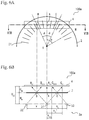
FIG. 6A is a plan view of the vicinity of a detector of a rotary encoder according to a second embodiment of the present invention -
FIG. 6B is a cross-sectional view taken along a line VIB-VIB ofFIG. 6A . -
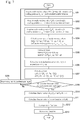
FIG. 7 is a flowchart illustrating self-calibration procedures of the rotary encoder of the second embodiment. - Preferred embodiments of the present invention will now be described with reference to the drawings; however, the present invention is not limited thereto. In the embodiments, the same constituent elements are denoted by the same reference numerals and will not redundantly be described.
- A rotary encoder (hereinafter simply referred to as an "encoder") 100 according to this embodiment is a so-called absolute encoder. The
encoder 100 includes arotary disk 2 fixed to a rotating shaft (not depicted), alight source 3 fixed to a rotating shaft bearing (not depicted), adetector 4 receiving the light from thelight source 3 via therotary disk 2, a convertingunit 5, aprocessing unit 6, and adisplay unit 7. - The
rotary disk 2 is a doughnut-shaped disk and has a periphery portion provided withslits 21 composed of narrow slits that mean 0 and wide slits that mean 1 and forming angle codes indicative of angles. - The
light source 3 includes a first light-emittingelement 31 and a second light-emittingelement 32, and the light-emitting elements are LEDs, for example. The light-emitting elements slits 21 of therotary disk 2 at a predetermined distance HDL (FIG. 2B ). The first light-emittingelement 31 and the second light-emittingelement 32 are disposed at a predetermined distance xL in a direction orthogonal to the diameter of the rotary disk. - The
detector 4 is a CCD linear sensor, for example, and is disposed on the side opposite to thelight source 3 with respect to therotary disk 2 so as to face thelight source 3 at a predetermined distance HDC (FIG. 2B ). - The converting
unit 5 is an A/D converter and converts a detection signal from thedetector 4 into a digital signal to output the signal to theprocessing unit 6. - The
processing unit 6 is a microcontroller equipped with a ROM, a RAM, etc. for a CPU, controls light emission of thelight source 3, decodes an angle code from the detection signal input from the convertingunit 5, applies a known interpolation process to calculate an angle, and outputs the angle to thedisplay unit 7 such as a liquid crystal display. - As depicted in
FIGS. 2A and 2B , thedetector 4 is disposed at a position orthogonal to the diameter of therotary disk 2 to face theslits 21. A foot of a perpendicular line drawn from a center O of therotary disk 2 to thedetector 4 is provided as the point A. In addition, an appropriate point of therotary disk 2 within a detection range of thedetector 4 is provided as the point B. Reference sign M denotes a direction in which the angle code indicates 0°, and a true angle of the point A created from an M direction is provided as θ, while a true angle of an angle AOB is provided as ϕ. Therefore, the position of the point A is the position of the angle θ, and the position of the point B is the position of the angle θ+ϕ. - In this state, the first light-
emitting element 31 is disposed at a position corresponding to the point A, and the second light-emitting element 32 is disposed at the predetermined distance xL away from the first light-emitting element 31 in an extending direction of thedetector 4. - As depicted in
FIG. 2B , if deflection is not taken into consideration, light emitted from the first light-emittingelement 31 and made incident on the point A is incident on a reading position ACI of thedetector 4. The light made incident on the point B is incident on a reading position BCI of thedetector 4. Theprocessing unit 6 can read respective angle codes of the point A and point B at the reading positions ACI and BCI and can apply the interpolation process to determine angle reading values fI(θ) and fI(θ+ϕ) at the point A and point B, respectively. In normal angle measurement, the angle reading value fI(θ) at the point A is the measurement value. - Since the reading values fI(θ) and fI(θ+ϕ) are periodic functions with a period of 360° and can therefore be expressed by
formulas 

- As depicted in
FIG. 2B , if deflection is not taken into consideration, light emitted from the second light-emittingelement 32 and made incident on the point B is incident on a reading position BCII of thedetector 4. Theprocessing unit 6 reads the angle code of the point B with thedetector 4 and applies the interpolation process to determine an angle reading value fII(θ+ϕ) at the point B. The details of the reading value fII(θ+ϕ) will be described later. - An influence of deflection on an angle reading value will be described with reference to
FIGS. 3A and 3B . The deflection means displacement of therotary disk 2 toward and away from thelight source 3 due to rotation. InFIGS. 3A and 3B , description will be made of the case that the deflection occurs in the direction toward the light source. - When the deflection ΔH occurs, the incident position on the
rotary disk 2 of the light emitted from the first light-emittingelement 31 for detection of the angle θ+ϕ is a point B' shifted from the point B by a distance ΔxDI. Therefore, the angle code of the point B' is read instead of that of the point B at the reading position BCI. Thus, the reading value fI(θ+ϕ) is (θ+ϕ)+ΔϕI (FIG. 3A ). Therefore, -ΔϕI is an error caused by the deflection of the rotary disk. - The deflection error ΔϕI at the position of the angle θ+ϕ can be calculated as follows.
- From
FIG. 3B , a relationship is as expressed byformula 3 among the deflection ΔH, a deviation ΔXDI of the incident position due to the deflection ΔH, a distance HLC from the first light-emittingelement 31 to thedetector 4, and a distance xCI between the reading positions ACI, BCI.
- Therefore, the deviation ΔxDI of the incident position can be expressed by
formula 4.
- From
FIG. 3A , the tangent of the angle cp can be expressed byformula 5 by using a distance xD between A and B and a length l of a perpendicular line drawn from the center O of the rotary disk to the point A.
- The tangent of (ϕ+ΔϕI) is expressed as
formula 6 by using the deviation ΔxDI of the incident position.
- Therefore, if ΔϕI is sufficiently small, ΔϕI can be approximated as in
formula 7.
- The deflection is also a periodic function with a period of 360 ° and is therefore expressed by formula 8 by using Fourier series.

- By adding this formula to
formula 1, a measured angle value fI(θ+ϕ) at the point B (angle θ+ϕ) with consideration given to the deflection can be expressed byformula 9.
- In the case of ϕ=0, xCI=0 is satisfied, and an error due to the deflection does not occur as expressed by formula 10. Specifically, the error due to the deflection does not affect the measurement of the angle θ itself.

- Description will be made of the influence of the deflection ΔH in the case of obtaining the angle reading value fII(θ+ϕ) at the point BCII when the light is emitted by the second light-emitting
element 32. The incident position on therotary disk 2 of the light emitted from the second light-emittingelement 32 is a point B" shifted from the point B by a distance ΔxDII. - A relationship at a position of θ+ϕ can be expressed by formula 11 from
FIG. 4 among the distance xL between the first light-emittingelement 31 and the second light-emittingelement 32, a distance (angle reading position) xCII between the reading positions ACI, BCII, the distance HLC from the second light-emittingelement 32 to thedetector 4, a deviation ΔxDII of the incident position due to the deflection ΔH, and the deflection ΔH.
- Therefore, the deviation ΔxDII of the incident position can be expressed by formula 12.

- Thus, as in the case that the light is emitted by the first light-emitting
element 31, the angle reading value fII(θ+ϕ) of the point BCII at the position of θ+ϕ can be expressed by formula 13.
- Therefore, a difference h(θ+ϕ) between the reading value fII(θ+ϕ) according to the second light-emitting
element 32 and the reading value fI(θ+ϕ) according to the first light-emittingelement 31 can be expressed by formula 14.
- From formula 8, Σ(ΔHi/HLC)∗{sin{i(θ+ϕ)+βi}=ΔϕI/(xCI/l) is acquired, and therefore, the error ΔϕI of the angle reading value due to the deflection at the position of θ+ϕ can be expressed by formula 15.

- Since the distance xL between the first light-emitting
element 31 and the second light-emittingelement 32 is known, and the distance (angle reading position) xCI between the reading positions ACI, BCI, and the distance (angle reading position) xCII between the reading positions ACI, BCII can also be acquired, the error ΔϕI of the angle reading value due to the deflection at the position of the angle θ+ϕ can be obtained. - A method of self-calibration of the
encoder 100 according to this embodiment is the same as the method disclosed inPatent Document 1 except that the error ΔϕI of the angle reading value due to the deflection is taken into consideration when the reading value fI(θ+ϕ) at the position of θ+ϕ is acquired, and the outline is as follows. - First, the difference gI(θ,ϕ) between the reading values fI(θ+ϕ) and fI(θ) can be expressed by a Fourier series as in formula 16 from
formulas Patent Document 1.


- Therefore, at a position with a rotation angle θj where the
rotary disk 2 is rotated by a predetermined angle (e.g., 5°) obtained by dividing 360° into N equal parts, reading values fI(θj), fI(θj+ϕ) at points A and B are acquired. Here, j=1, 2, 3,... N-1. By calculating gI(θj,ϕ)=fI(θj+ϕ)-fI(θj) for each predetermined angle θj, the respective coefficients Bo, Bi, γi of the Fourier series in formula 16 can be calculated by a known method, and cp, Ai, αi can be calculated from formulas 17, 18, 19. Therefore, the true angle θ can be obtained from formula 20, which is deformation offormula 1.
- Self-calibration procedures of the
encoder 100 according to this embodiment will be described with reference toFIG. 5 . The following automatic calibration process is usually carried out by theprocessing unit 6. - When the self-calibration is started, in step S101, the light is emitted by the first light-emitting
element 31 so as to acquire the reading values fI(θj), fI(θj+ϕ) of the reading positions ACI, BCI on thedetector 4 and the distance (angle reading position) xCI between ACI and BCI, and this is carried out a predetermined number of times. After the measurement, the light emission of the first light-emittingelement 31 is stopped. - Next, in step S102, the light is emitted by the second light-emitting
element 32 so as to acquire the reading value fII(θj+ϕ) of the reading position BCII on thedetector 4 and the distance (angle reading position) XCII between ACI and BCII, and this is carried out a predetermined number of times. After the measurement, the light emission of the second light-emittingelement 32 is stopped. - Next, in step S103, averages of the reading values fI(θj), fI(θj+ϕ), fII(θj+ϕ), the distance (angle reading position) xCI between ACI and BCI, and the distance (angle reading position) xCII between ACI and BCII are calculated.
- Next, in step S104, a difference h (θj+ϕ) =fII(θj+ϕ)-fI(θj+ϕ) between the reading values fII(θj+ϕ) and fI(θj+ϕ) at θ+ϕ is calculated and stored.
- Next, in step S105, the error ΔϕI of the angle reading value due to the deflection at the position of θ+ϕ is calculated by formula 15 and stored.
- Next, in step S106, a difference gI(θj,ϕ) between the reading value fI(θj+ϕ)-ΔϕI and the reading value fI(θ) taking the influence of the deflection into consideration is calculated and stored.
- Next, in step S107, it is judged whether all possible data has been acquired, i.e., whether g(θj,ϕ) has been acquired for each predetermined angle θj. For example, it is judged for θ whether gI(θj,ϕ) has been acquired at intervals of 5 ° traversing 360 °.
- If all possible data has not been acquired (No), the process proceeds to step S107, the
rotary disk 2 is manually or automatically rotated by a predetermined angle, and the process returns to step S101. Thereafter, steps S101 to S107 are repeated to obtain and store gI(θj,ϕ) for each predetermined angle θj. - When the predetermined number of times of data acquisition has been completed in step S109 (Yes), the process proceeds to step S108 to calculate, based on gI(θj,ϕ) for each predetermined angle θj, coefficients B0, Bn, γn of the Fourier series of gI(θ, ϕ) described in formula 16.
- Next, in step S110, coefficients An, αn of the Fourier series of the error function E(θ) of the reading value f(θ) are calculated based on the coefficients B0, Bn, γn.
- Next, in step S111, the error function E(θ) is obtained based on the coefficients acquired in step S110 and is stored, and the process ends.
- By carrying out the automatic calibration of the
encoder 100 as described above, the true angle θ can be accurately obtained from the reading value f(θ) by usingformula 1 in subsequent measurements. - According to the
encoder 100 according to this embodiment, when a rotation angle of the rotary disk is provided as θ and an arbitrary angle from the rotation angle θ within a reading range on the detector is provided as ϕ, the second light-emitting element is disposed at a predetermined distance in addition to the first light-emitting element for measuring the rotation angle θ, and this enables measurement of the angle reading value fI(θ+ϕ) using the first light-emittingelement 31 and the angle reading value fII(θ+ϕ) using the second light-emittingelement 32 at the position of the angle θ+ϕ as well as the respective angle reading positions on thedetectors 4. Using these measured values and the known distance between the light-emitting elements makes it possible to obtain the error ΔϕI of the angle reading value at the angle θ+ϕ due to the deflection at the position of the angle θ+ϕ. - Therefore, the error function can be calculated by using the reading value fI(θj+ϕ)-ΔϕI taking the error ΔϕI of the angle reading value due to the deflection, and the self-calibration can be carried out with this error function, which enables highly accurate self-calibration.
-
FIGS. 6A and 6B depict anencoder 100a according to a second embodiment. Theencoder 100a has substantially the same configuration as theencoder 100 according to the first embodiment except that alight source 3a further includes a third light-emittingelement 33. The third light-emittingelement 33 is disposed symmetrically to the second light-emittingelement 32 with respect to the first light-emittingelement 31, that is, a perpendicular line drawn from the center O of therotary disk 2 to the point A. - The third light-emitting
element 33 is used for reading an angle at a position separated from the point A by the angle cp in the direction opposite to the point B, that is, at a position of an angle θ-ϕ. An error Δ(-ϕI) of an angle reading value due to the deflection at the angle 8-cp is also calculated by the same method as ΔϕI. - Next, self-calibration procedures of the encoder 100a according to this embodiment will be described with reference to
FIG. 7 . The basic process is the same as the procedures according to the first embodiment, and therefore, the same process will be cited without description. - When the self-calibration is started, in step S201, in addition to the process of step S101, an angle reading value fI(θj-ϕ) and a distance (angle reading position) xCI' between ACI and CCI are acquired, and this is carried out a predetermined number of times. After the measurement, the light emission of the first light-emitting
element 31 is stopped. - Next, in step S202, the measurement according to the second light-emitting element is carried out as in step S102.
- Next, in step S203, the light is emitted by the third light-emitting
element 33 so as to acquire a reading value fIII(θj-ϕ) of a reading position BCIII on thedetector 4 and a distance (angle reading position) xCIII between ACI and BCIII, and this is carried out a predetermined number of times. After the measurement, the light emission of the third light-emittingelement 33 is stopped. - Next, in step S204, averages of the reading values fI(θj), fI(θj+ϕ), fII(θj+ϕ), fIII(θj-ϕ) and the angle reading positions xCI, xCI' acquired in steps S201 to S203 are calculated.
- Next, in step S205, h(θj+ϕ) and h(θj-ϕ) are calculated and stored as in step S104.
- Next, in step S206, the errors ΔϕI, Δ(-ϕI) of the angle reading values due to the deflection at the respective positions of θ+ϕ, θ-ϕ are calculated and stored as in step S105.
- Next, in step S207, gI(θj,ϕ) and gI(θj,ϕ) are calculated and stored as in step S106,.
- Thereafter, the processes in steps S208 to S211 are carried out as in steps S107 to S110 to calculate an error function of fI(θ) obtained from each of θ+ϕ and θ-ϕ.
- The error function is averaged in step S212, the error function is stored in step S213, and the process ends.
- According to this embodiment, since the reading errors of the reading values at the angles θ+ϕ and θ+ϕ can be averaged, higher calibration accuracy can be achieved.
- Although the preferred embodiments of the present invention have been described, the embodiments are examples of the present invention and can be combined based on the knowledge of those skilled in the art, and such embodiments fall within the scope of the present invention.
-
- 2
- rotary disk
- 3, 3a
- light source
- 31
- first light-emitting element
- 32
- second light-emitting element
- 33
- third light-emitting element
- 4
- detector
- 6
- processing unit
- 100, 100a
- rotary encoder
Claims (2)
- A rotary encoder comprising:a rotary disk with an angle code;a light source for irradiating the angle code;a detector for reading the angle code; anda processing unit for acquiring a reading value f(θ) based on the angle code read by the detector, whereinthe light source includes a plurality of light-emitting elements, wherein a first light-emitting element is disposed at a position corresponding to an angle θ of the rotation, wherein a second light-emitting element is disposed at a predetermined distance xL away from the first light-emitting element, and whereinevery time the rotary disk is rotated by a predetermined angle, where a rotation angle of the rotary disk is provided as θ and an arbitrary angle from the rotation angle θ within a reading range on the detector is provided as cp, the processing unit is configured to acquire reading values fI(θ+ϕ) and fI(θ) within a reading range on the detector in the case of using the first light-emitting element and a reading value fII(θ+ϕ) on the detector in the case of using the second light-emitting element, to calculate a reading value error ΔϕI due to deflection at an angle θ+ϕ based on a difference h(θ+ϕ) between the reading value fII(θ+ϕ) and the reading value fI(θ+ϕ), to obtain a difference gI(θ,ϕ) between the reading values fI(θ+ϕ) and fI(θ) such that the reading value error ΔϕI is reflected, and to self-calibrate the reading value fI(θ) based on a change in the difference gI(θ,ϕ).
- The rotary encoder according to claim 1, wherein
the light source includes a third light-emitting element disposed at a position symmetrical to the second light-emitting element with respect to the first light-emitting element, and wherein
the processing unit is configured to acquire a reading value fI(θ-ϕ) within a reading range on the detector in the case of using the first light-emitting element and a reading value fIII(θ-ϕ) on the detector in the case of using the third light-emitting element, to calculate a reading value error Δ(-ϕI) due to deflection at an angle θ+ϕ based on a difference h(θ-ϕ) between the reading value fIII(θ-ϕ) and the reading value fI(θ-ϕ), to obtain a difference gI(θ,-ϕ) between the reading values fI(θ-ϕ) and fI(θ) such that the reading value error Δ(-ϕI) is reflected, to average changes in the difference gI(θ,ϕ) and the difference gI(θ,-ϕ), and to self-calibrate the reading value fI(θ).
Applications Claiming Priority (1)
| Application Number | Priority Date | Filing Date | Title |
|---|---|---|---|
| JP2018185902A JP7107806B2 (en) | 2018-09-28 | 2018-09-28 | Rotary encoder |
Publications (2)
| Publication Number | Publication Date |
|---|---|
| EP3628979A1 true EP3628979A1 (en) | 2020-04-01 |
| EP3628979B1 EP3628979B1 (en) | 2021-05-26 |
Family
ID=67997514
Family Applications (1)
| Application Number | Title | Priority Date | Filing Date |
|---|---|---|---|
| EP19198099.4A Active EP3628979B1 (en) | 2018-09-28 | 2019-09-18 | Rotary encoder |
Country Status (3)
| Country | Link |
|---|---|
| US (1) | US11293786B2 (en) |
| EP (1) | EP3628979B1 (en) |
| JP (1) | JP7107806B2 (en) |
Families Citing this family (1)
| Publication number | Priority date | Publication date | Assignee | Title |
|---|---|---|---|---|
| WO2022254863A1 (en) * | 2021-05-31 | 2022-12-08 | 日本電産株式会社 | Angle detection method and angle detection device |
Citations (3)
| Publication number | Priority date | Publication date | Assignee | Title |
|---|---|---|---|---|
| JPS4824415B1 (en) | 1970-12-02 | 1973-07-20 | ||
| US6145368A (en) * | 1998-06-03 | 2000-11-14 | Micron Electronics, Inc. | Method for calibrating rotary encoder with multiple calibration points |
| US20100181468A1 (en) * | 2006-01-27 | 2010-07-22 | Sokkia Co., Ltd. | Rotary encoder |
Family Cites Families (6)
| Publication number | Priority date | Publication date | Assignee | Title |
|---|---|---|---|---|
| JPS59183305A (en) * | 1983-04-01 | 1984-10-18 | Ricoh Co Ltd | position detection device |
| US7012703B2 (en) * | 2003-08-21 | 2006-03-14 | Ams Controls | Automatic encoder resolution calibration and length measurement system and method |
| JP2005345356A (en) * | 2004-06-04 | 2005-12-15 | Kyoritsu Denki Kk | Method and apparatus for measuring mounting position in flatness measurement |
| US7414547B2 (en) * | 2006-12-22 | 2008-08-19 | 3M Innovative Properties Company | Method and system for calibrating a rotary encoder and making a high resolution rotary encoder |
| JP5808230B2 (en) * | 2011-11-14 | 2015-11-10 | 株式会社ハーモニック・ドライブ・システムズ | Autonomous calibration method for angle detector, angle detector, circumferential scale calibration device, and angle detector calibration device |
| EP2920554B1 (en) * | 2012-11-14 | 2018-11-07 | Baumüller Nürnberg GmbH | Method for calibrating a rotary encoder |
-
2018
- 2018-09-28 JP JP2018185902A patent/JP7107806B2/en active Active
-
2019
- 2019-09-11 US US16/567,466 patent/US11293786B2/en active Active
- 2019-09-18 EP EP19198099.4A patent/EP3628979B1/en active Active
Patent Citations (3)
| Publication number | Priority date | Publication date | Assignee | Title |
|---|---|---|---|---|
| JPS4824415B1 (en) | 1970-12-02 | 1973-07-20 | ||
| US6145368A (en) * | 1998-06-03 | 2000-11-14 | Micron Electronics, Inc. | Method for calibrating rotary encoder with multiple calibration points |
| US20100181468A1 (en) * | 2006-01-27 | 2010-07-22 | Sokkia Co., Ltd. | Rotary encoder |
Also Published As
| Publication number | Publication date |
|---|---|
| JP2020056618A (en) | 2020-04-09 |
| US20200103255A1 (en) | 2020-04-02 |
| JP7107806B2 (en) | 2022-07-27 |
| US11293786B2 (en) | 2022-04-05 |
| EP3628979B1 (en) | 2021-05-26 |
Similar Documents
| Publication | Publication Date | Title |
|---|---|---|
| US7825367B2 (en) | Rotary encoder | |
| EP2500695B1 (en) | Angle detecting device with complex self-calibration function | |
| EP2778623B1 (en) | Position detection apparatus, lens apparatus, image pickup system, and machine tool apparatus | |
| US8610050B2 (en) | Optical displacement detection apparatus | |
| US6922899B2 (en) | Rotary encoder | |
| US9146136B2 (en) | Axis run-out measuring method and angle detecting device with self-calibration function having axis run-out measuring function | |
| US20120248300A2 (en) | Angular correction method for rotary encoder | |
| EP2466271B1 (en) | Method, computer program product and rotary encoder for estimation of eccentric value | |
| EP3628979B1 (en) | Rotary encoder | |
| US9000356B2 (en) | Encoder | |
| EP2733469B1 (en) | Measurement apparatus, measurement method, and absolute encoder | |
| JP6161325B2 (en) | Absolute encoder | |
| US8670635B2 (en) | Method and device for determining the position, radius and/or shape deviation of a ring structure | |
| KR20130138470A (en) | Position measuring apparatus and position measuring method | |
| Geckeler et al. | Determining interpolation errors of angle encoders by error-separating shearing techniques | |
| Krause et al. | Angle metrology at the PTB: current status and developments | |
| KR20090111545A (en) | Optical Self-Calibration Algorithm Minimizing the Effect of Rotation Error |
Legal Events
| Date | Code | Title | Description |
|---|---|---|---|
| PUAI | Public reference made under article 153(3) epc to a published international application that has entered the european phase |
Free format text: ORIGINAL CODE: 0009012 |
|
| STAA | Information on the status of an ep patent application or granted ep patent |
Free format text: STATUS: THE APPLICATION HAS BEEN PUBLISHED |
|
| AK | Designated contracting states |
Kind code of ref document: A1 Designated state(s): AL AT BE BG CH CY CZ DE DK EE ES FI FR GB GR HR HU IE IS IT LI LT LU LV MC MK MT NL NO PL PT RO RS SE SI SK SM TR |
|
| AX | Request for extension of the european patent |
Extension state: BA ME |
|
| STAA | Information on the status of an ep patent application or granted ep patent |
Free format text: STATUS: REQUEST FOR EXAMINATION WAS MADE |
|
| 17P | Request for examination filed |
Effective date: 20200923 |
|
| RBV | Designated contracting states (corrected) |
Designated state(s): AL AT BE BG CH CY CZ DE DK EE ES FI FR GB GR HR HU IE IS IT LI LT LU LV MC MK MT NL NO PL PT RO RS SE SI SK SM TR |
|
| GRAP | Despatch of communication of intention to grant a patent |
Free format text: ORIGINAL CODE: EPIDOSNIGR1 |
|
| STAA | Information on the status of an ep patent application or granted ep patent |
Free format text: STATUS: GRANT OF PATENT IS INTENDED |
|
| INTG | Intention to grant announced |
Effective date: 20210120 |
|
| GRAS | Grant fee paid |
Free format text: ORIGINAL CODE: EPIDOSNIGR3 |
|
| GRAA | (expected) grant |
Free format text: ORIGINAL CODE: 0009210 |
|
| STAA | Information on the status of an ep patent application or granted ep patent |
Free format text: STATUS: THE PATENT HAS BEEN GRANTED |
|
| AK | Designated contracting states |
Kind code of ref document: B1 Designated state(s): AL AT BE BG CH CY CZ DE DK EE ES FI FR GB GR HR HU IE IS IT LI LT LU LV MC MK MT NL NO PL PT RO RS SE SI SK SM TR |
|
| REG | Reference to a national code |
Ref country code: GB Ref legal event code: FG4D |
|
| REG | Reference to a national code |
Ref country code: CH Ref legal event code: EP |
|
| REG | Reference to a national code |
Ref country code: DE Ref legal event code: R096 Ref document number: 602019004882 Country of ref document: DE |
|
| REG | Reference to a national code |
Ref country code: AT Ref legal event code: REF Ref document number: 1396677 Country of ref document: AT Kind code of ref document: T Effective date: 20210615 |
|
| REG | Reference to a national code |
Ref country code: IE Ref legal event code: FG4D |
|
| REG | Reference to a national code |
Ref country code: LT Ref legal event code: MG9D |
|
| REG | Reference to a national code |
Ref country code: AT Ref legal event code: MK05 Ref document number: 1396677 Country of ref document: AT Kind code of ref document: T Effective date: 20210526 |
|
| PG25 | Lapsed in a contracting state [announced via postgrant information from national office to epo] |
Ref country code: FI Free format text: LAPSE BECAUSE OF FAILURE TO SUBMIT A TRANSLATION OF THE DESCRIPTION OR TO PAY THE FEE WITHIN THE PRESCRIBED TIME-LIMIT Effective date: 20210526 Ref country code: HR Free format text: LAPSE BECAUSE OF FAILURE TO SUBMIT A TRANSLATION OF THE DESCRIPTION OR TO PAY THE FEE WITHIN THE PRESCRIBED TIME-LIMIT Effective date: 20210526 Ref country code: LT Free format text: LAPSE BECAUSE OF FAILURE TO SUBMIT A TRANSLATION OF THE DESCRIPTION OR TO PAY THE FEE WITHIN THE PRESCRIBED TIME-LIMIT Effective date: 20210526 Ref country code: AT Free format text: LAPSE BECAUSE OF FAILURE TO SUBMIT A TRANSLATION OF THE DESCRIPTION OR TO PAY THE FEE WITHIN THE PRESCRIBED TIME-LIMIT Effective date: 20210526 Ref country code: BG Free format text: LAPSE BECAUSE OF FAILURE TO SUBMIT A TRANSLATION OF THE DESCRIPTION OR TO PAY THE FEE WITHIN THE PRESCRIBED TIME-LIMIT Effective date: 20210826 |
|
| REG | Reference to a national code |
Ref country code: NL Ref legal event code: MP Effective date: 20210526 |
|
| PG25 | Lapsed in a contracting state [announced via postgrant information from national office to epo] |
Ref country code: LV Free format text: LAPSE BECAUSE OF FAILURE TO SUBMIT A TRANSLATION OF THE DESCRIPTION OR TO PAY THE FEE WITHIN THE PRESCRIBED TIME-LIMIT Effective date: 20210526 Ref country code: PL Free format text: LAPSE BECAUSE OF FAILURE TO SUBMIT A TRANSLATION OF THE DESCRIPTION OR TO PAY THE FEE WITHIN THE PRESCRIBED TIME-LIMIT Effective date: 20210526 Ref country code: NO Free format text: LAPSE BECAUSE OF FAILURE TO SUBMIT A TRANSLATION OF THE DESCRIPTION OR TO PAY THE FEE WITHIN THE PRESCRIBED TIME-LIMIT Effective date: 20210826 Ref country code: PT Free format text: LAPSE BECAUSE OF FAILURE TO SUBMIT A TRANSLATION OF THE DESCRIPTION OR TO PAY THE FEE WITHIN THE PRESCRIBED TIME-LIMIT Effective date: 20210927 Ref country code: RS Free format text: LAPSE BECAUSE OF FAILURE TO SUBMIT A TRANSLATION OF THE DESCRIPTION OR TO PAY THE FEE WITHIN THE PRESCRIBED TIME-LIMIT Effective date: 20210526 Ref country code: SE Free format text: LAPSE BECAUSE OF FAILURE TO SUBMIT A TRANSLATION OF THE DESCRIPTION OR TO PAY THE FEE WITHIN THE PRESCRIBED TIME-LIMIT Effective date: 20210526 Ref country code: GR Free format text: LAPSE BECAUSE OF FAILURE TO SUBMIT A TRANSLATION OF THE DESCRIPTION OR TO PAY THE FEE WITHIN THE PRESCRIBED TIME-LIMIT Effective date: 20210827 Ref country code: IS Free format text: LAPSE BECAUSE OF FAILURE TO SUBMIT A TRANSLATION OF THE DESCRIPTION OR TO PAY THE FEE WITHIN THE PRESCRIBED TIME-LIMIT Effective date: 20210926 |
|
| PG25 | Lapsed in a contracting state [announced via postgrant information from national office to epo] |
Ref country code: NL Free format text: LAPSE BECAUSE OF FAILURE TO SUBMIT A TRANSLATION OF THE DESCRIPTION OR TO PAY THE FEE WITHIN THE PRESCRIBED TIME-LIMIT Effective date: 20210526 |
|
| PG25 | Lapsed in a contracting state [announced via postgrant information from national office to epo] |
Ref country code: SM Free format text: LAPSE BECAUSE OF FAILURE TO SUBMIT A TRANSLATION OF THE DESCRIPTION OR TO PAY THE FEE WITHIN THE PRESCRIBED TIME-LIMIT Effective date: 20210526 Ref country code: RO Free format text: LAPSE BECAUSE OF FAILURE TO SUBMIT A TRANSLATION OF THE DESCRIPTION OR TO PAY THE FEE WITHIN THE PRESCRIBED TIME-LIMIT Effective date: 20210526 Ref country code: DK Free format text: LAPSE BECAUSE OF FAILURE TO SUBMIT A TRANSLATION OF THE DESCRIPTION OR TO PAY THE FEE WITHIN THE PRESCRIBED TIME-LIMIT Effective date: 20210526 Ref country code: CZ Free format text: LAPSE BECAUSE OF FAILURE TO SUBMIT A TRANSLATION OF THE DESCRIPTION OR TO PAY THE FEE WITHIN THE PRESCRIBED TIME-LIMIT Effective date: 20210526 Ref country code: SK Free format text: LAPSE BECAUSE OF FAILURE TO SUBMIT A TRANSLATION OF THE DESCRIPTION OR TO PAY THE FEE WITHIN THE PRESCRIBED TIME-LIMIT Effective date: 20210526 Ref country code: ES Free format text: LAPSE BECAUSE OF FAILURE TO SUBMIT A TRANSLATION OF THE DESCRIPTION OR TO PAY THE FEE WITHIN THE PRESCRIBED TIME-LIMIT Effective date: 20210526 Ref country code: EE Free format text: LAPSE BECAUSE OF FAILURE TO SUBMIT A TRANSLATION OF THE DESCRIPTION OR TO PAY THE FEE WITHIN THE PRESCRIBED TIME-LIMIT Effective date: 20210526 |
|
| REG | Reference to a national code |
Ref country code: DE Ref legal event code: R097 Ref document number: 602019004882 Country of ref document: DE |
|
| PLBE | No opposition filed within time limit |
Free format text: ORIGINAL CODE: 0009261 |
|
| STAA | Information on the status of an ep patent application or granted ep patent |
Free format text: STATUS: NO OPPOSITION FILED WITHIN TIME LIMIT |
|
| 26N | No opposition filed |
Effective date: 20220301 |
|
| REG | Reference to a national code |
Ref country code: BE Ref legal event code: MM Effective date: 20210930 |
|
| PG25 | Lapsed in a contracting state [announced via postgrant information from national office to epo] |
Ref country code: IS Free format text: LAPSE BECAUSE OF FAILURE TO SUBMIT A TRANSLATION OF THE DESCRIPTION OR TO PAY THE FEE WITHIN THE PRESCRIBED TIME-LIMIT Effective date: 20210926 Ref country code: MC Free format text: LAPSE BECAUSE OF FAILURE TO SUBMIT A TRANSLATION OF THE DESCRIPTION OR TO PAY THE FEE WITHIN THE PRESCRIBED TIME-LIMIT Effective date: 20210526 Ref country code: AL Free format text: LAPSE BECAUSE OF FAILURE TO SUBMIT A TRANSLATION OF THE DESCRIPTION OR TO PAY THE FEE WITHIN THE PRESCRIBED TIME-LIMIT Effective date: 20210526 |
|
| PG25 | Lapsed in a contracting state [announced via postgrant information from national office to epo] |
Ref country code: LU Free format text: LAPSE BECAUSE OF NON-PAYMENT OF DUE FEES Effective date: 20210918 Ref country code: IT Free format text: LAPSE BECAUSE OF FAILURE TO SUBMIT A TRANSLATION OF THE DESCRIPTION OR TO PAY THE FEE WITHIN THE PRESCRIBED TIME-LIMIT Effective date: 20210526 Ref country code: IE Free format text: LAPSE BECAUSE OF NON-PAYMENT OF DUE FEES Effective date: 20210918 Ref country code: FR Free format text: LAPSE BECAUSE OF NON-PAYMENT OF DUE FEES Effective date: 20210930 Ref country code: BE Free format text: LAPSE BECAUSE OF NON-PAYMENT OF DUE FEES Effective date: 20210930 |
|
| PG25 | Lapsed in a contracting state [announced via postgrant information from national office to epo] |
Ref country code: CY Free format text: LAPSE BECAUSE OF FAILURE TO SUBMIT A TRANSLATION OF THE DESCRIPTION OR TO PAY THE FEE WITHIN THE PRESCRIBED TIME-LIMIT Effective date: 20210526 |
|
| PG25 | Lapsed in a contracting state [announced via postgrant information from national office to epo] |
Ref country code: HU Free format text: LAPSE BECAUSE OF FAILURE TO SUBMIT A TRANSLATION OF THE DESCRIPTION OR TO PAY THE FEE WITHIN THE PRESCRIBED TIME-LIMIT; INVALID AB INITIO Effective date: 20190918 |
|
| PG25 | Lapsed in a contracting state [announced via postgrant information from national office to epo] |
Ref country code: MK Free format text: LAPSE BECAUSE OF FAILURE TO SUBMIT A TRANSLATION OF THE DESCRIPTION OR TO PAY THE FEE WITHIN THE PRESCRIBED TIME-LIMIT Effective date: 20210526 |
|
| GBPC | Gb: european patent ceased through non-payment of renewal fee |
Effective date: 20230918 |
|
| PG25 | Lapsed in a contracting state [announced via postgrant information from national office to epo] |
Ref country code: GB Free format text: LAPSE BECAUSE OF NON-PAYMENT OF DUE FEES Effective date: 20230918 |
|
| PG25 | Lapsed in a contracting state [announced via postgrant information from national office to epo] |
Ref country code: GB Free format text: LAPSE BECAUSE OF NON-PAYMENT OF DUE FEES Effective date: 20230918 |
|
| PG25 | Lapsed in a contracting state [announced via postgrant information from national office to epo] |
Ref country code: MT Free format text: LAPSE BECAUSE OF FAILURE TO SUBMIT A TRANSLATION OF THE DESCRIPTION OR TO PAY THE FEE WITHIN THE PRESCRIBED TIME-LIMIT Effective date: 20210526 |
|
| REG | Reference to a national code |
Ref country code: CH Ref legal event code: U11 Free format text: ST27 STATUS EVENT CODE: U-0-0-U10-U11 (AS PROVIDED BY THE NATIONAL OFFICE) Effective date: 20251001 |
|
| PGFP | Annual fee paid to national office [announced via postgrant information from national office to epo] |
Ref country code: DE Payment date: 20250730 Year of fee payment: 7 |
|
| PG25 | Lapsed in a contracting state [announced via postgrant information from national office to epo] |
Ref country code: TR Free format text: LAPSE BECAUSE OF FAILURE TO SUBMIT A TRANSLATION OF THE DESCRIPTION OR TO PAY THE FEE WITHIN THE PRESCRIBED TIME-LIMIT Effective date: 20210526 |
|
| PGFP | Annual fee paid to national office [announced via postgrant information from national office to epo] |
Ref country code: CH Payment date: 20251001 Year of fee payment: 7 |