EP3628898A1 - Three-position poppet valve - Google Patents
Three-position poppet valve Download PDFInfo
- Publication number
- EP3628898A1 EP3628898A1 EP19195999.8A EP19195999A EP3628898A1 EP 3628898 A1 EP3628898 A1 EP 3628898A1 EP 19195999 A EP19195999 A EP 19195999A EP 3628898 A1 EP3628898 A1 EP 3628898A1
- Authority
- EP
- European Patent Office
- Prior art keywords
- valve
- spring
- compressed
- fluid flow
- piston
- Prior art date
- Legal status (The legal status is an assumption and is not a legal conclusion. Google has not performed a legal analysis and makes no representation as to the accuracy of the status listed.)
- Granted
Links
Images
Classifications
-
- F—MECHANICAL ENGINEERING; LIGHTING; HEATING; WEAPONS; BLASTING
- F16—ENGINEERING ELEMENTS AND UNITS; GENERAL MEASURES FOR PRODUCING AND MAINTAINING EFFECTIVE FUNCTIONING OF MACHINES OR INSTALLATIONS; THERMAL INSULATION IN GENERAL
- F16K—VALVES; TAPS; COCKS; ACTUATING-FLOATS; DEVICES FOR VENTING OR AERATING
- F16K17/00—Safety valves; Equalising valves, e.g. pressure relief valves
- F16K17/20—Excess-flow valves
- F16K17/22—Excess-flow valves actuated by the difference of pressure between two places in the flow line
- F16K17/24—Excess-flow valves actuated by the difference of pressure between two places in the flow line acting directly on the cutting-off member
- F16K17/28—Excess-flow valves actuated by the difference of pressure between two places in the flow line acting directly on the cutting-off member operating in one direction only
- F16K17/30—Excess-flow valves actuated by the difference of pressure between two places in the flow line acting directly on the cutting-off member operating in one direction only spring-loaded
-
- F—MECHANICAL ENGINEERING; LIGHTING; HEATING; WEAPONS; BLASTING
- F16—ENGINEERING ELEMENTS AND UNITS; GENERAL MEASURES FOR PRODUCING AND MAINTAINING EFFECTIVE FUNCTIONING OF MACHINES OR INSTALLATIONS; THERMAL INSULATION IN GENERAL
- F16K—VALVES; TAPS; COCKS; ACTUATING-FLOATS; DEVICES FOR VENTING OR AERATING
- F16K1/00—Lift valves or globe valves, i.e. cut-off apparatus with closure members having at least a component of their opening and closing motion perpendicular to the closing faces
- F16K1/12—Lift valves or globe valves, i.e. cut-off apparatus with closure members having at least a component of their opening and closing motion perpendicular to the closing faces with streamlined valve member around which the fluid flows when the valve is opened
- F16K1/126—Lift valves or globe valves, i.e. cut-off apparatus with closure members having at least a component of their opening and closing motion perpendicular to the closing faces with streamlined valve member around which the fluid flows when the valve is opened actuated by fluid
-
- F—MECHANICAL ENGINEERING; LIGHTING; HEATING; WEAPONS; BLASTING
- F02—COMBUSTION ENGINES; HOT-GAS OR COMBUSTION-PRODUCT ENGINE PLANTS
- F02C—GAS-TURBINE PLANTS; AIR INTAKES FOR JET-PROPULSION PLANTS; CONTROLLING FUEL SUPPLY IN AIR-BREATHING JET-PROPULSION PLANTS
- F02C7/00—Features, components parts, details or accessories, not provided for in, or of interest apart form groups F02C1/00 - F02C6/00; Air intakes for jet-propulsion plants
- F02C7/22—Fuel supply systems
- F02C7/232—Fuel valves; Draining valves or systems
-
- F—MECHANICAL ENGINEERING; LIGHTING; HEATING; WEAPONS; BLASTING
- F16—ENGINEERING ELEMENTS AND UNITS; GENERAL MEASURES FOR PRODUCING AND MAINTAINING EFFECTIVE FUNCTIONING OF MACHINES OR INSTALLATIONS; THERMAL INSULATION IN GENERAL
- F16K—VALVES; TAPS; COCKS; ACTUATING-FLOATS; DEVICES FOR VENTING OR AERATING
- F16K31/00—Actuating devices; Operating means; Releasing devices
- F16K31/12—Actuating devices; Operating means; Releasing devices actuated by fluid
- F16K31/122—Actuating devices; Operating means; Releasing devices actuated by fluid the fluid acting on a piston
- F16K31/1221—Actuating devices; Operating means; Releasing devices actuated by fluid the fluid acting on a piston one side of the piston being spring-loaded
-
- F—MECHANICAL ENGINEERING; LIGHTING; HEATING; WEAPONS; BLASTING
- F16—ENGINEERING ELEMENTS AND UNITS; GENERAL MEASURES FOR PRODUCING AND MAINTAINING EFFECTIVE FUNCTIONING OF MACHINES OR INSTALLATIONS; THERMAL INSULATION IN GENERAL
- F16K—VALVES; TAPS; COCKS; ACTUATING-FLOATS; DEVICES FOR VENTING OR AERATING
- F16K31/00—Actuating devices; Operating means; Releasing devices
- F16K31/12—Actuating devices; Operating means; Releasing devices actuated by fluid
- F16K31/122—Actuating devices; Operating means; Releasing devices actuated by fluid the fluid acting on a piston
- F16K31/124—Actuating devices; Operating means; Releasing devices actuated by fluid the fluid acting on a piston servo actuated
Definitions
- This application relates generally to a poppet valve.
- Poppet valves generally include an aperture and a poppet head that seats against the aperture to control fluid flow through the aperture. The poppet head is moved with respect to the aperture, typically moved via a solenoid valve, servo-valve, or torque/electric motor, that applies a force to the plug to bring it to a desired location.
- a valve according to an example of the present disclosure includes a poppet head configured to move with respect to a valve outlet of the valve.
- a first spring is configured to be compressed with a force generated by fluid flow through the valve, and compression of the first spring allows the poppet head to move towards the valve outlet.
- a second spring is configured to allow the poppet head to move toward the valve outlet when compressed.
- the second spring is configured to be compressed by an outside force.
- the outside force is provided by a muscle fluid controlled by a solenoid valve.
- a piston is connected to the poppet head at a first end of the piston, and a flange at a second end of the piston opposite the first end.
- the first and second springs are arranged concentrically around the piston.
- the first and second springs and the piston are arranged in an inner housing.
- a stopper is arranged between the first and second springs in the inner housing.
- the stopper includes a body portion configured to engage a lip in the inner housing and a leg configured to engage the flange.
- the body portion engages the lip when the first spring is compressed but not when the second spring is compressed.
- the leg engages the flange when the first and second springs are compressed.
- the first spring has a lower resistance than the second spring.
- the fluid flow is fluid flow in one of a pneumatic, hydraulic, or fuel system in a gas turbine engine.
- valve controls fluid flow in a pneumatic, hydraulic, or fuel system for a gas turbine engine.
- the poppet head is configured to contact a seat of the valve outlet when the first and second springs are compressed.
- a method of controlling fluid flow includes a moving a poppet head towards a valve outlet.
- a first spring is compressed with a force generated by fluid flow through a valve.
- the poppet head is moved to a fully closed position against the valve outlet.
- a second spring is compressed with an outside force.
- a method for controlling fluid flow includes providing the outside force with a muscle fluid controlled by a solenoid valve.
- a method for controlling fluid flow includes compressing the first spring with less force than the second spring.
- the poppet head is attached to a piston, and the poppet head, the piston, the first spring, and the second spring are arranged in an inner housing.
- a stopper is arranged between the first and second springs, and the first spring is compressed between the stopper and a flange on the piston.
- a stopper is arranged between the first and second spring, and the second spring is compressed between the stopper and the inner housing.
- the fluid flow is fluid flow in one of a pneumatic, hydraulic, or fuel system in a gas turbine engine.
- a poppet valve includes a poppet head that seats against an aperture to control flow of fluid through the aperture.
- Certain applications for instance, pneumatic, hydraulic, and fuel systems in a gas turbine engine, utilize three-position poppet valves, e.g., poppet valves that are operable in a fully open position, a fully closed position, and an intermediate position.
- the present poppet valve includes an actuation mechanism that holds the poppet valve in one of the three positions without the use of a servo-valve or torque/electric motor.
- Some three-position poppet valves that utilize a servo valve/motor are held in the intermediate position by creating a force balance at the intermediate position.
- a force margin is a measure of the force balance, and compares the driving force behind an actuator to a resisting force of the actuation.
- the force margin is zero in the intermediate position because the servo valve/motor provides a driving force equal to the resisting force.
- the present poppet valve is held in the intermediate position with a non-zero force margin, e.g., the driving force is not equal to the resisting force.
- eliminating the servo-vale/torque motor reduces the complexity of the software logic for controlling the valve, the complexity of the system hardware, and allows the use of a solenoid, reducing cost of the system.
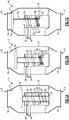
- Figures 1a-c schematically show the present poppet valve 10.
- the poppet valve 10 is in a fully open position.
- the poppet valve is in an intermediate position.
- the poppet valve is in a fully closed position.
- the poppet valve 10 includes a housing 12 with an inlet 13 and an inlet flange 14.
- the poppet valve 10 also includes an outlet 15 and an outlet flange 16.
- the poppet valve 10 controls fluid flow from the inlet flange 14 to the outlet flange 16 via movement of a poppet head 18.
- the poppet head 18 is attached to one end of a piston 20. At the opposite end from the poppet head 18, the piston 20 has a flange 22.
- the piston 20 is arranged in an inner housing 24. Within the inner housing 24 and concentrically around the piston 20 are two springs 26, 28. A stopper 30 is arranged in between the springs 26, 28.
- the stopper includes a body portion 31 and a leg portion 32 extending from the body portion 31.
- the body portion 31 is configured to engage a lip 33 in the inner housing 24 and the leg portion 32 is configured to engage the flange 22 of the piston 20 in some positions, as will become apparent from the subsequent disclosure.
- the stopper 30 includes seals that seal against the inner housing 24.
- the piston 20 also has a seal which seals against stopper 30 to prevent solenoid 36 commanded muscle pressure (discussed below) from entering a lower portion of inner housing 24 which spring 28 is in.
- a muscle flange 34 extends through the inner housing 24 and housing 12 to enable a muscle source (e.g., a fluid) to assist spring 26 in holding the valve in the intermediate position as shown in Figure 1B .
- the muscle source is controlled by a pneumatic solenoid valve 36, which allows the muscle fluid to fill an upper portion of inner housing 24 of spring 26 (to assist the spring 26 and maintain it in the position of Figures 1A and B ) or vent it to ambient pressure (e.g., no muscle pressure assisting the spring 26).
- the muscle source controlled by the solenoid 36 can be the inlet 14 pressure source to the valve or another muscle source.
- both springs 26, 28 are fully expanded, or in a non-compressed state.
- the stopper 30 rests on the lip 33.
- the poppet head 18 is spaced away from the outlet flange 16 so that fluid can flow through the poppet valve 10.
- the poppet valve 10 takes advantage of pressure created by fluid flow from the inlet flange 14 to the outlet flange 16. This pressure urges the poppet head 18 towards the outlet flange 16 and the spring 28 to compress.
- the flange 22 on the piston 20, which is attached to the poppet head 18, also moves towards the outlet flange 16, such that the leg portion 32 of the stopper 30 engages the flange 22. This compresses 28 between the flange 22 and the body portion 31 of the stopper 30.
- Muscle pressure is also supplied via the solenoid 36 to the inner housing 24 in order to act on stopper 30 to assist spring 26 in holding the poppet head 18 in the passive position.
- the solenoid 36 can be actuated by a controller according to any known logic.
- this intermediate state is said to be "passively" actuated.
- the poppet valve 10 moves into the intermediate state. Furthermore, since no driving force is provided, the force margin for the passive actuation is non-zero.
- the solenoid 36 is actuated to cause the spring 26 to compress.
- the solenoid 36 blocks the muscle pressure and vents the inner housing 24 to ambient pressure, allowing the poppet head 18 to translate to the fully closed position.
- the solenoid 36 can be actuated by a controller according to any known logic.
- the stopper 30 and piston 20 move toward the outlet flange 16, urging the poppet head 18 against a seat 21 of the outlet flange 16 to block fluid flow through the outlet flange 16.
- the body portion 31 of the stopper 30 disengages from the lip 33, but the leg 32 remain engaged with the flange 22.
- the spring 28 remains compressed between the flange 22 and the stopper 30.
- the spring 26 is compressed between the body portion 31 of the stopper 30 and the inner housing 24. Accordingly, when both springs 26, 28 are compressed, the poppet head 18 is in contact with the seat 21 of the outlet flange 16.
- the actuation of the solenoid 36 (e.g., an outside force) provides an "active" actuation, as compared to the passive actuation discussed above, which only utilizes the force of fluid flow through the valve 10.
- the "passive spring” 28 has a lower spring resistance than the "active spring” 26.
- the resistance of the passive spring 28 is selected to allow the passive actuation in the intermediate state to occur at a certain desired fluid flow associated with a certain desired pressure.
Landscapes
- Engineering & Computer Science (AREA)
- General Engineering & Computer Science (AREA)
- Mechanical Engineering (AREA)
- Physics & Mathematics (AREA)
- Fluid Mechanics (AREA)
- Chemical & Material Sciences (AREA)
- Combustion & Propulsion (AREA)
- Magnetically Actuated Valves (AREA)
- Lift Valve (AREA)
Abstract
Description
- This application relates generally to a poppet valve.
- Engines, and in particular gas turbine engines such as for aircraft, have pneumatic, hydraulic, and/or fueldraulic systems that require controlling fluid flow for operation. Fluid flow control is accomplished by various valves. One example type of valve is a poppet valve. Poppet valves generally include an aperture and a poppet head that seats against the aperture to control fluid flow through the aperture. The poppet head is moved with respect to the aperture, typically moved via a solenoid valve, servo-valve, or torque/electric motor, that applies a force to the plug to bring it to a desired location.
- A valve according to an example of the present disclosure includes a poppet head configured to move with respect to a valve outlet of the valve. A first spring is configured to be compressed with a force generated by fluid flow through the valve, and compression of the first spring allows the poppet head to move towards the valve outlet. A second spring is configured to allow the poppet head to move toward the valve outlet when compressed.
- In a further embodiment according to any of the foregoing embodiments, the second spring is configured to be compressed by an outside force.
- In a further embodiment according to any of the foregoing embodiments, the outside force is provided by a muscle fluid controlled by a solenoid valve.
- In a further embodiment according to any of the foregoing embodiments, a piston is connected to the poppet head at a first end of the piston, and a flange at a second end of the piston opposite the first end.
- In a further embodiment according to any of the foregoing embodiments, the first and second springs are arranged concentrically around the piston.
- In a further embodiment according to any of the foregoing embodiments, the first and second springs and the piston are arranged in an inner housing.
- In a further embodiment according to any of the foregoing embodiments, a stopper is arranged between the first and second springs in the inner housing.
- In a further embodiment according to any of the foregoing embodiments, the stopper includes a body portion configured to engage a lip in the inner housing and a leg configured to engage the flange.
- In a further embodiment according to any of the foregoing embodiments, the body portion engages the lip when the first spring is compressed but not when the second spring is compressed.
- In a further embodiment according to any of the foregoing embodiments, the leg engages the flange when the first and second springs are compressed.
- In a further embodiment according to any of the foregoing embodiments, the first spring has a lower resistance than the second spring.
- In a further embodiment according to any of the foregoing embodiments, the fluid flow is fluid flow in one of a pneumatic, hydraulic, or fuel system in a gas turbine engine.
- In a further embodiment according to any of the foregoing embodiments, the valve controls fluid flow in a pneumatic, hydraulic, or fuel system for a gas turbine engine.
- In a further embodiment according to any of the foregoing embodiments, the poppet head is configured to contact a seat of the valve outlet when the first and second springs are compressed.
- A method of controlling fluid flow according to an example of the present disclosure includes a moving a poppet head towards a valve outlet. A first spring is compressed with a force generated by fluid flow through a valve. The poppet head is moved to a fully closed position against the valve outlet. A second spring is compressed with an outside force.
- In a further embodiment according to any of the foregoing embodiments, a method for controlling fluid flow includes providing the outside force with a muscle fluid controlled by a solenoid valve.
- In a further embodiment according to any of the foregoing embodiments, a method for controlling fluid flow includes compressing the first spring with less force than the second spring.
- In a further embodiment according to any of the foregoing embodiments, the poppet head is attached to a piston, and the poppet head, the piston, the first spring, and the second spring are arranged in an inner housing.
- In a further embodiment according to any of the foregoing embodiments, a stopper is arranged between the first and second springs, and the first spring is compressed between the stopper and a flange on the piston.
- In a further embodiment according to any of the foregoing embodiments, a stopper is arranged between the first and second spring, and the second spring is compressed between the stopper and the inner housing.
- In a further embodiment according to any of the foregoing embodiments, the fluid flow is fluid flow in one of a pneumatic, hydraulic, or fuel system in a gas turbine engine.
-
-
Figure 1a schematically shows a poppet valve in a fully closed state. -
Figure 1b schematically shows a poppet valve in an intermediate state. -
Figure 1c schematically shows a poppet valve in a fully open state. - A poppet valve includes a poppet head that seats against an aperture to control flow of fluid through the aperture. Certain applications, for instance, pneumatic, hydraulic, and fuel systems in a gas turbine engine, utilize three-position poppet valves, e.g., poppet valves that are operable in a fully open position, a fully closed position, and an intermediate position. The present poppet valve includes an actuation mechanism that holds the poppet valve in one of the three positions without the use of a servo-valve or torque/electric motor.
- Some three-position poppet valves that utilize a servo valve/motor are held in the intermediate position by creating a force balance at the intermediate position. A force margin is a measure of the force balance, and compares the driving force behind an actuator to a resisting force of the actuation. Force margin is generally determined as follows: force margin = driving force/resisting force - 1. In the servo valve/motor example, the force margin is zero in the intermediate position because the servo valve/motor provides a driving force equal to the resisting force. On the other hand, the present poppet valve is held in the intermediate position with a non-zero force margin, e.g., the driving force is not equal to the resisting force. Because the driving force and resisting force do not have to be balanced, eliminating the servo-vale/torque motor reduces the complexity of the software logic for controlling the valve, the complexity of the system hardware, and allows the use of a solenoid, reducing cost of the system.
-
Figures 1a-c schematically show the present poppet valve 10. InFigure 1a , the poppet valve 10 is in a fully open position. InFigure 1b , the poppet valve is in an intermediate position. InFigure 1c , the poppet valve is in a fully closed position. - The poppet valve 10 includes a
housing 12 with aninlet 13 and aninlet flange 14. The poppet valve 10 also includes anoutlet 15 and anoutlet flange 16. The poppet valve 10 controls fluid flow from theinlet flange 14 to theoutlet flange 16 via movement of apoppet head 18. Thepoppet head 18 is attached to one end of apiston 20. At the opposite end from thepoppet head 18, thepiston 20 has aflange 22. - The
piston 20 is arranged in aninner housing 24. Within theinner housing 24 and concentrically around thepiston 20 are twosprings stopper 30 is arranged in between thesprings body portion 31 and aleg portion 32 extending from thebody portion 31. Thebody portion 31 is configured to engage alip 33 in theinner housing 24 and theleg portion 32 is configured to engage theflange 22 of thepiston 20 in some positions, as will become apparent from the subsequent disclosure. In one example, thestopper 30 includes seals that seal against theinner housing 24. In one example, thepiston 20 also has a seal which seals againststopper 30 to preventsolenoid 36 commanded muscle pressure (discussed below) from entering a lower portion ofinner housing 24 whichspring 28 is in. - A
muscle flange 34 extends through theinner housing 24 andhousing 12 to enable a muscle source (e.g., a fluid) to assistspring 26 in holding the valve in the intermediate position as shown inFigure 1B . The muscle source is controlled by apneumatic solenoid valve 36, which allows the muscle fluid to fill an upper portion ofinner housing 24 of spring 26 (to assist thespring 26 and maintain it in the position ofFigures 1A and B ) or vent it to ambient pressure (e.g., no muscle pressure assisting the spring 26). The muscle source controlled by thesolenoid 36 can be theinlet 14 pressure source to the valve or another muscle source. - Turning now to the operation of the poppet valve 10, in the open state of
Figure 1a , bothsprings stopper 30 rests on thelip 33. Thepoppet head 18 is spaced away from theoutlet flange 16 so that fluid can flow through the poppet valve 10. - In the intermediate state, shown in
Figure 1b , the poppet valve 10 takes advantage of pressure created by fluid flow from theinlet flange 14 to theoutlet flange 16. This pressure urges thepoppet head 18 towards theoutlet flange 16 and thespring 28 to compress. Theflange 22 on thepiston 20, which is attached to thepoppet head 18, also moves towards theoutlet flange 16, such that theleg portion 32 of thestopper 30 engages theflange 22. This compresses 28 between theflange 22 and thebody portion 31 of thestopper 30. In the intermediate position, thebody portion 31 of thestopper 30 still rests on thelip 33. Muscle pressure is also supplied via thesolenoid 36 to theinner housing 24 in order to act onstopper 30 to assistspring 26 in holding thepoppet head 18 in the passive position. Thesolenoid 36 can be actuated by a controller according to any known logic. - Because the poppet valve 10 is controlling the flow of fluid and using pressure generated by the same fluid to cause actuation of the valve mechanism, this intermediate state is said to be "passively" actuated. When the pressure of the fluid flow overcomes the resistance of the
spring 28, the poppet valve 10 moves into the intermediate state. Furthermore, since no driving force is provided, the force margin for the passive actuation is non-zero. - In the fully closed state, shown in
Figure 1c , thesolenoid 36 is actuated to cause thespring 26 to compress. Thesolenoid 36 blocks the muscle pressure and vents theinner housing 24 to ambient pressure, allowing thepoppet head 18 to translate to the fully closed position. Thesolenoid 36 can be actuated by a controller according to any known logic. In the fully closed state, thestopper 30 andpiston 20 move toward theoutlet flange 16, urging thepoppet head 18 against a seat 21 of theoutlet flange 16 to block fluid flow through theoutlet flange 16. In this position, thebody portion 31 of thestopper 30 disengages from thelip 33, but theleg 32 remain engaged with theflange 22. Thespring 28 remains compressed between theflange 22 and thestopper 30. Thespring 26 is compressed between thebody portion 31 of thestopper 30 and theinner housing 24. Accordingly, when both springs 26, 28 are compressed, thepoppet head 18 is in contact with the seat 21 of theoutlet flange 16. - The actuation of the solenoid 36 (e.g., an outside force) provides an "active" actuation, as compared to the passive actuation discussed above, which only utilizes the force of fluid flow through the valve 10.
- In one example, the "passive spring" 28 has a lower spring resistance than the "active spring" 26. In a further example, the resistance of the
passive spring 28 is selected to allow the passive actuation in the intermediate state to occur at a certain desired fluid flow associated with a certain desired pressure. - Although example embodiments have been disclosed, a worker of ordinary skill in this art would recognize that certain modifications would come within the scope of this disclosure. For that reason, the following claims should be studied to determine the scope and content of this disclosure.
Claims (15)
- A valve, comprising:a poppet head (18) configured to move with respect to a valve outlet of the valve;a first spring (26) configured to be compressed with a force generated by fluid flow through the valve, wherein compression of the first spring (26) allows the poppet head (18) to move towards the valve outlet; anda second spring (28), configured to allow the poppet head (18) to move toward the valve outlet when compressed.
- The valve of claim 1, wherein the second spring (28) is configured to be compressed by an outside force, and preferably wherein the outside force is provided by a muscle fluid controlled by a solenoid valve.
- The valve of claims 1 or 2, further comprising a piston (20) connected to the poppet head (18) at a first end of the piston, and a flange (22) at a second end of the piston opposite the first end, and preferably wherein the first and second springs (26, 28) are arranged concentrically around the piston (20), and more preferably wherein the first and second springs (26, 28) and the piston (20) are arranged in an inner housing (24), and preferably further comprising a stopper arranged between the first and second springs (26, 28) in the inner housing (24), and more preferably wherein the stopper includes a body portion (31) configured to engage a lip (33) in the inner housing and a leg configured to engage the flange (22).
- The valve of claim 3, wherein the body portion (31) engages the lip (33) when the first spring (26) is compressed but not when the second spring (28) is compressed.
- The valve of claim 3, wherein the leg (32) engages the flange (22) when the first and second springs (26, 28) are compressed.
- The valve of any preceding claim, wherein the first spring (26) has a lower resistance than the second spring (28).
- The valve of any preceding claim, wherein the fluid flow is fluid flow in one of a pneumatic, hydraulic, or fuel system in a gas turbine engine.
- The valve of any preceding claim, wherein the valve controls fluid flow in a pneumatic, hydraulic, or fuel system for a gas turbine engine.
- The valve of any preceding claim, wherein the poppet head is configured to contact a seat of the valve outlet when the first and second springs are compressed.
- A method of controlling fluid flow, comprising:moving a poppet head towards a valve outlet;compressing a first spring with a force generated by fluid flow through a valve;moving the poppet head to a fully closed position against the valve outlet; andcompressing a second spring with an outside force.
- The method of claim 10, further comprising providing the outside force with a muscle fluid controlled by a solenoid valve.
- The method of claim 10 or 11, further comprising compressing the first spring with less force than the second spring.
- The method of any of claims 10-12, wherein the poppet head is attached to a piston, and the poppet head, the piston, the first spring, and the second spring are arranged in an inner housing.
- The method of claim 13, wherein a stopper is arranged between the first and second springs, and the first spring is compressed between the stopper and a flange on the piston; or wherein a stopper is arranged between the first and second spring, and the second spring is compressed between the stopper and the inner housing.
- The method of any of claims 10-14, wherein the fluid flow is fluid flow in one of a pneumatic, hydraulic, or fuel system in a gas turbine engine.
Applications Claiming Priority (1)
| Application Number | Priority Date | Filing Date | Title |
|---|---|---|---|
| US16/145,877 US10975969B2 (en) | 2018-09-28 | 2018-09-28 | Three-position poppet valve |
Publications (2)
| Publication Number | Publication Date |
|---|---|
| EP3628898A1 true EP3628898A1 (en) | 2020-04-01 |
| EP3628898B1 EP3628898B1 (en) | 2024-08-07 |
Family
ID=67875387
Family Applications (1)
| Application Number | Title | Priority Date | Filing Date |
|---|---|---|---|
| EP19195999.8A Active EP3628898B1 (en) | 2018-09-28 | 2019-09-06 | Three-position poppet valve |
Country Status (2)
| Country | Link |
|---|---|
| US (1) | US10975969B2 (en) |
| EP (1) | EP3628898B1 (en) |
Families Citing this family (1)
| Publication number | Priority date | Publication date | Assignee | Title |
|---|---|---|---|---|
| JP7624856B2 (en) * | 2021-03-15 | 2025-01-31 | 本田技研工業株式会社 | Fuel Supply System |
Citations (5)
| Publication number | Priority date | Publication date | Assignee | Title |
|---|---|---|---|---|
| US2834377A (en) * | 1955-03-18 | 1958-05-13 | Robert M Bragg | Safety flow valve |
| GB809531A (en) * | 1954-11-05 | 1959-02-25 | English Electric Co Ltd | Improvements in and relating to constant mass flow air valves |
| US7225830B1 (en) * | 2005-02-09 | 2007-06-05 | Kershaw Charles H | Fluid control valve |
| US20170101937A1 (en) * | 2015-10-13 | 2017-04-13 | Honeywell International Inc. | Flow limiting duct vent valves and gas turbine engine bleed air systems including the same |
| CA3046144A1 (en) * | 2016-12-08 | 2018-06-14 | Rosen Swiss Ag | Bypass valve and pig having a bypass valve |
Family Cites Families (12)
| Publication number | Priority date | Publication date | Assignee | Title |
|---|---|---|---|---|
| US3818921A (en) * | 1972-09-15 | 1974-06-25 | Bendix Corp | Fluid flow throttling valve |
| US4610265A (en) * | 1984-12-12 | 1986-09-09 | Sundstrand Corporation | Turbine compressor stall recovery valve |
| JP2515407B2 (en) * | 1989-09-30 | 1996-07-10 | 旭有機材工業 株式会社 | Constant flow valve |
| AT403948B (en) * | 1994-07-29 | 1998-06-25 | Hoerbiger Ventilwerke Ag | INTAKE CONTROL VALVE FOR ROTATIONAL COMPRESSORS |
| US6095187A (en) | 1998-11-05 | 2000-08-01 | Interface Devices, Inc. | Solenoid-actuated zero-leakage fail-safe three-position poppet-style four-way hydraulic directional control valve |
| US6213447B1 (en) | 1999-07-29 | 2001-04-10 | Delphi Technologies, Inc. | Poppet value having a compliant shaft guide and compliant valve head |
| US6945508B2 (en) | 2003-05-29 | 2005-09-20 | Caterpillar Inc. | Electromagnetic control valve |
| ITTO20060131A1 (en) | 2006-02-24 | 2007-08-25 | Fiat Auto Spa | CONTROL DEVICE FOR THE HANDLING OF A VALVE IN PARTICULAR OF AN INTERNAL COMBUSTION ENGINE SUCTION VALVE |
| US7669830B2 (en) | 2006-10-25 | 2010-03-02 | Honeywell International Inc. | Three position shutoff valve |
| US7921880B2 (en) | 2007-08-20 | 2011-04-12 | Hydraforce, Inc. | Three-way poppet valve with intermediate pilot port |
| US9309979B2 (en) | 2010-04-28 | 2016-04-12 | Larry Rayner Russell | Self piloted check valve |
| EP2833033B1 (en) | 2013-08-01 | 2016-06-22 | C.R.F. Società Consortile per Azioni | Electrically actuated valve having two ways and three positions |
-
2018
- 2018-09-28 US US16/145,877 patent/US10975969B2/en active Active
-
2019
- 2019-09-06 EP EP19195999.8A patent/EP3628898B1/en active Active
Patent Citations (5)
| Publication number | Priority date | Publication date | Assignee | Title |
|---|---|---|---|---|
| GB809531A (en) * | 1954-11-05 | 1959-02-25 | English Electric Co Ltd | Improvements in and relating to constant mass flow air valves |
| US2834377A (en) * | 1955-03-18 | 1958-05-13 | Robert M Bragg | Safety flow valve |
| US7225830B1 (en) * | 2005-02-09 | 2007-06-05 | Kershaw Charles H | Fluid control valve |
| US20170101937A1 (en) * | 2015-10-13 | 2017-04-13 | Honeywell International Inc. | Flow limiting duct vent valves and gas turbine engine bleed air systems including the same |
| CA3046144A1 (en) * | 2016-12-08 | 2018-06-14 | Rosen Swiss Ag | Bypass valve and pig having a bypass valve |
Also Published As
| Publication number | Publication date |
|---|---|
| EP3628898B1 (en) | 2024-08-07 |
| US20200103045A1 (en) | 2020-04-02 |
| US10975969B2 (en) | 2021-04-13 |
Similar Documents
| Publication | Publication Date | Title |
|---|---|---|
| KR101236593B1 (en) | Fluid-working machine | |
| EP2391842B1 (en) | Actuator having an override apparatus | |
| EP3561264B1 (en) | Passive active poppet-type bleed valves | |
| EP1295057B1 (en) | Crashproof instant-on valve | |
| EP3569921A1 (en) | Poppet type pneumatic valve for inflation system | |
| EP2769100B1 (en) | Volume booster with seat load bias | |
| EP1207330A2 (en) | Proportional control valve assembly for exhaust gas recirculation system | |
| US6966285B1 (en) | Engine valve actuation control and method | |
| US8656941B1 (en) | Flow control valve | |
| EP3129660B1 (en) | Servo valve | |
| JP2015503720A (en) | Fail-safe device for use with fluid valves | |
| CN109823331A (en) | A kind of vehicle electrically controlling Pneumatic braking system compositely proportional relay valve and control method | |
| EP3247886B1 (en) | Pneumatic trip valve partial stroking arrangement | |
| EP3628898B1 (en) | Three-position poppet valve | |
| WO2012121826A1 (en) | Bypass arrangement for valve actuator | |
| US6857618B2 (en) | Device for controlling a gas exchange valve | |
| US4817660A (en) | Pressure regulating valve | |
| EP3862260B1 (en) | Emergency door actuation | |
| JP5248859B2 (en) | Pneumatic system with one or more piston / cylinder arrangements | |
| EP1723319A1 (en) | A method of generating pressure pulses, a pressure pulse generator and a piston engine provided therewith | |
| JP2007525620A (en) | Pressure pulse generation method, pressure pulse generator, and piston engine provided with the pressure pulse generator | |
| US11391301B2 (en) | Electrohydraulic poppet valve device control that maintains the last commanded position of a device upon power interruption and provides back-up position control | |
| US20140311576A1 (en) | Integrated Hydraulic Accumulator Dual Shut-Off Valve | |
| RU2584044C1 (en) | Valve | |
| WO2016039718A1 (en) | Brake cylinder maintaining reference |
Legal Events
| Date | Code | Title | Description |
|---|---|---|---|
| PUAI | Public reference made under article 153(3) epc to a published international application that has entered the european phase |
Free format text: ORIGINAL CODE: 0009012 |
|
| STAA | Information on the status of an ep patent application or granted ep patent |
Free format text: STATUS: THE APPLICATION HAS BEEN PUBLISHED |
|
| AK | Designated contracting states |
Kind code of ref document: A1 Designated state(s): AL AT BE BG CH CY CZ DE DK EE ES FI FR GB GR HR HU IE IS IT LI LT LU LV MC MK MT NL NO PL PT RO RS SE SI SK SM TR |
|
| AX | Request for extension of the european patent |
Extension state: BA ME |
|
| STAA | Information on the status of an ep patent application or granted ep patent |
Free format text: STATUS: REQUEST FOR EXAMINATION WAS MADE |
|
| 17P | Request for examination filed |
Effective date: 20200930 |
|
| RBV | Designated contracting states (corrected) |
Designated state(s): AL AT BE BG CH CY CZ DE DK EE ES FI FR GB GR HR HU IE IS IT LI LT LU LV MC MK MT NL NO PL PT RO RS SE SI SK SM TR |
|
| STAA | Information on the status of an ep patent application or granted ep patent |
Free format text: STATUS: EXAMINATION IS IN PROGRESS |
|
| 17Q | First examination report despatched |
Effective date: 20210212 |
|
| GRAP | Despatch of communication of intention to grant a patent |
Free format text: ORIGINAL CODE: EPIDOSNIGR1 |
|
| STAA | Information on the status of an ep patent application or granted ep patent |
Free format text: STATUS: GRANT OF PATENT IS INTENDED |
|
| INTG | Intention to grant announced |
Effective date: 20240305 |
|
| GRAS | Grant fee paid |
Free format text: ORIGINAL CODE: EPIDOSNIGR3 |
|
| GRAA | (expected) grant |
Free format text: ORIGINAL CODE: 0009210 |
|
| STAA | Information on the status of an ep patent application or granted ep patent |
Free format text: STATUS: THE PATENT HAS BEEN GRANTED |
|
| AK | Designated contracting states |
Kind code of ref document: B1 Designated state(s): AL AT BE BG CH CY CZ DE DK EE ES FI FR GB GR HR HU IE IS IT LI LT LU LV MC MK MT NL NO PL PT RO RS SE SI SK SM TR |
|
| REG | Reference to a national code |
Ref country code: GB Ref legal event code: FG4D |
|
| REG | Reference to a national code |
Ref country code: CH Ref legal event code: EP |
|
| REG | Reference to a national code |
Ref country code: IE Ref legal event code: FG4D |
|
| REG | Reference to a national code |
Ref country code: DE Ref legal event code: R096 Ref document number: 602019056470 Country of ref document: DE |
|
| REG | Reference to a national code |
Ref country code: LT Ref legal event code: MG9D |
|
| REG | Reference to a national code |
Ref country code: NL Ref legal event code: MP Effective date: 20240807 |
|
| PG25 | Lapsed in a contracting state [announced via postgrant information from national office to epo] |
Ref country code: NO Free format text: LAPSE BECAUSE OF FAILURE TO SUBMIT A TRANSLATION OF THE DESCRIPTION OR TO PAY THE FEE WITHIN THE PRESCRIBED TIME-LIMIT Effective date: 20241107 |
|
| REG | Reference to a national code |
Ref country code: AT Ref legal event code: MK05 Ref document number: 1711277 Country of ref document: AT Kind code of ref document: T Effective date: 20240807 |
|
| PG25 | Lapsed in a contracting state [announced via postgrant information from national office to epo] |
Ref country code: NL Free format text: LAPSE BECAUSE OF FAILURE TO SUBMIT A TRANSLATION OF THE DESCRIPTION OR TO PAY THE FEE WITHIN THE PRESCRIBED TIME-LIMIT Effective date: 20240807 Ref country code: FI Free format text: LAPSE BECAUSE OF FAILURE TO SUBMIT A TRANSLATION OF THE DESCRIPTION OR TO PAY THE FEE WITHIN THE PRESCRIBED TIME-LIMIT Effective date: 20240807 Ref country code: GR Free format text: LAPSE BECAUSE OF FAILURE TO SUBMIT A TRANSLATION OF THE DESCRIPTION OR TO PAY THE FEE WITHIN THE PRESCRIBED TIME-LIMIT Effective date: 20241108 Ref country code: PT Free format text: LAPSE BECAUSE OF FAILURE TO SUBMIT A TRANSLATION OF THE DESCRIPTION OR TO PAY THE FEE WITHIN THE PRESCRIBED TIME-LIMIT Effective date: 20241209 Ref country code: PL Free format text: LAPSE BECAUSE OF FAILURE TO SUBMIT A TRANSLATION OF THE DESCRIPTION OR TO PAY THE FEE WITHIN THE PRESCRIBED TIME-LIMIT Effective date: 20240807 |
|
| PG25 | Lapsed in a contracting state [announced via postgrant information from national office to epo] |
Ref country code: BG Free format text: LAPSE BECAUSE OF FAILURE TO SUBMIT A TRANSLATION OF THE DESCRIPTION OR TO PAY THE FEE WITHIN THE PRESCRIBED TIME-LIMIT Effective date: 20240807 |
|
| PG25 | Lapsed in a contracting state [announced via postgrant information from national office to epo] |
Ref country code: LV Free format text: LAPSE BECAUSE OF FAILURE TO SUBMIT A TRANSLATION OF THE DESCRIPTION OR TO PAY THE FEE WITHIN THE PRESCRIBED TIME-LIMIT Effective date: 20240807 |
|
| PG25 | Lapsed in a contracting state [announced via postgrant information from national office to epo] |
Ref country code: AT Free format text: LAPSE BECAUSE OF FAILURE TO SUBMIT A TRANSLATION OF THE DESCRIPTION OR TO PAY THE FEE WITHIN THE PRESCRIBED TIME-LIMIT Effective date: 20240807 Ref country code: IS Free format text: LAPSE BECAUSE OF FAILURE TO SUBMIT A TRANSLATION OF THE DESCRIPTION OR TO PAY THE FEE WITHIN THE PRESCRIBED TIME-LIMIT Effective date: 20241207 |
|
| PG25 | Lapsed in a contracting state [announced via postgrant information from national office to epo] |
Ref country code: HR Free format text: LAPSE BECAUSE OF FAILURE TO SUBMIT A TRANSLATION OF THE DESCRIPTION OR TO PAY THE FEE WITHIN THE PRESCRIBED TIME-LIMIT Effective date: 20240807 |
|
| PG25 | Lapsed in a contracting state [announced via postgrant information from national office to epo] |
Ref country code: RS Free format text: LAPSE BECAUSE OF FAILURE TO SUBMIT A TRANSLATION OF THE DESCRIPTION OR TO PAY THE FEE WITHIN THE PRESCRIBED TIME-LIMIT Effective date: 20241107 Ref country code: ES Free format text: LAPSE BECAUSE OF FAILURE TO SUBMIT A TRANSLATION OF THE DESCRIPTION OR TO PAY THE FEE WITHIN THE PRESCRIBED TIME-LIMIT Effective date: 20240807 |
|
| PG25 | Lapsed in a contracting state [announced via postgrant information from national office to epo] |
Ref country code: RS Free format text: LAPSE BECAUSE OF FAILURE TO SUBMIT A TRANSLATION OF THE DESCRIPTION OR TO PAY THE FEE WITHIN THE PRESCRIBED TIME-LIMIT Effective date: 20241107 Ref country code: PT Free format text: LAPSE BECAUSE OF FAILURE TO SUBMIT A TRANSLATION OF THE DESCRIPTION OR TO PAY THE FEE WITHIN THE PRESCRIBED TIME-LIMIT Effective date: 20241209 Ref country code: PL Free format text: LAPSE BECAUSE OF FAILURE TO SUBMIT A TRANSLATION OF THE DESCRIPTION OR TO PAY THE FEE WITHIN THE PRESCRIBED TIME-LIMIT Effective date: 20240807 Ref country code: NO Free format text: LAPSE BECAUSE OF FAILURE TO SUBMIT A TRANSLATION OF THE DESCRIPTION OR TO PAY THE FEE WITHIN THE PRESCRIBED TIME-LIMIT Effective date: 20241107 Ref country code: NL Free format text: LAPSE BECAUSE OF FAILURE TO SUBMIT A TRANSLATION OF THE DESCRIPTION OR TO PAY THE FEE WITHIN THE PRESCRIBED TIME-LIMIT Effective date: 20240807 Ref country code: LV Free format text: LAPSE BECAUSE OF FAILURE TO SUBMIT A TRANSLATION OF THE DESCRIPTION OR TO PAY THE FEE WITHIN THE PRESCRIBED TIME-LIMIT Effective date: 20240807 Ref country code: IS Free format text: LAPSE BECAUSE OF FAILURE TO SUBMIT A TRANSLATION OF THE DESCRIPTION OR TO PAY THE FEE WITHIN THE PRESCRIBED TIME-LIMIT Effective date: 20241207 Ref country code: HR Free format text: LAPSE BECAUSE OF FAILURE TO SUBMIT A TRANSLATION OF THE DESCRIPTION OR TO PAY THE FEE WITHIN THE PRESCRIBED TIME-LIMIT Effective date: 20240807 Ref country code: GR Free format text: LAPSE BECAUSE OF FAILURE TO SUBMIT A TRANSLATION OF THE DESCRIPTION OR TO PAY THE FEE WITHIN THE PRESCRIBED TIME-LIMIT Effective date: 20241108 Ref country code: FI Free format text: LAPSE BECAUSE OF FAILURE TO SUBMIT A TRANSLATION OF THE DESCRIPTION OR TO PAY THE FEE WITHIN THE PRESCRIBED TIME-LIMIT Effective date: 20240807 Ref country code: ES Free format text: LAPSE BECAUSE OF FAILURE TO SUBMIT A TRANSLATION OF THE DESCRIPTION OR TO PAY THE FEE WITHIN THE PRESCRIBED TIME-LIMIT Effective date: 20240807 Ref country code: BG Free format text: LAPSE BECAUSE OF FAILURE TO SUBMIT A TRANSLATION OF THE DESCRIPTION OR TO PAY THE FEE WITHIN THE PRESCRIBED TIME-LIMIT Effective date: 20240807 Ref country code: AT Free format text: LAPSE BECAUSE OF FAILURE TO SUBMIT A TRANSLATION OF THE DESCRIPTION OR TO PAY THE FEE WITHIN THE PRESCRIBED TIME-LIMIT Effective date: 20240807 |
|
| PG25 | Lapsed in a contracting state [announced via postgrant information from national office to epo] |
Ref country code: DK Free format text: LAPSE BECAUSE OF FAILURE TO SUBMIT A TRANSLATION OF THE DESCRIPTION OR TO PAY THE FEE WITHIN THE PRESCRIBED TIME-LIMIT Effective date: 20240807 Ref country code: RO Free format text: LAPSE BECAUSE OF FAILURE TO SUBMIT A TRANSLATION OF THE DESCRIPTION OR TO PAY THE FEE WITHIN THE PRESCRIBED TIME-LIMIT Effective date: 20240807 Ref country code: SM Free format text: LAPSE BECAUSE OF FAILURE TO SUBMIT A TRANSLATION OF THE DESCRIPTION OR TO PAY THE FEE WITHIN THE PRESCRIBED TIME-LIMIT Effective date: 20240807 |
|
| PG25 | Lapsed in a contracting state [announced via postgrant information from national office to epo] |
Ref country code: EE Free format text: LAPSE BECAUSE OF FAILURE TO SUBMIT A TRANSLATION OF THE DESCRIPTION OR TO PAY THE FEE WITHIN THE PRESCRIBED TIME-LIMIT Effective date: 20240807 |
|
| PG25 | Lapsed in a contracting state [announced via postgrant information from national office to epo] |
Ref country code: CZ Free format text: LAPSE BECAUSE OF FAILURE TO SUBMIT A TRANSLATION OF THE DESCRIPTION OR TO PAY THE FEE WITHIN THE PRESCRIBED TIME-LIMIT Effective date: 20240807 |
|
| PG25 | Lapsed in a contracting state [announced via postgrant information from national office to epo] |
Ref country code: SK Free format text: LAPSE BECAUSE OF FAILURE TO SUBMIT A TRANSLATION OF THE DESCRIPTION OR TO PAY THE FEE WITHIN THE PRESCRIBED TIME-LIMIT Effective date: 20240807 |
|
| REG | Reference to a national code |
Ref country code: CH Ref legal event code: PL |
|
| REG | Reference to a national code |
Ref country code: DE Ref legal event code: R097 Ref document number: 602019056470 Country of ref document: DE |
|
| PG25 | Lapsed in a contracting state [announced via postgrant information from national office to epo] |
Ref country code: LU Free format text: LAPSE BECAUSE OF NON-PAYMENT OF DUE FEES Effective date: 20240906 |
|
| PLBE | No opposition filed within time limit |
Free format text: ORIGINAL CODE: 0009261 |
|
| STAA | Information on the status of an ep patent application or granted ep patent |
Free format text: STATUS: NO OPPOSITION FILED WITHIN TIME LIMIT |
|
| PG25 | Lapsed in a contracting state [announced via postgrant information from national office to epo] |
Ref country code: MC Free format text: LAPSE BECAUSE OF FAILURE TO SUBMIT A TRANSLATION OF THE DESCRIPTION OR TO PAY THE FEE WITHIN THE PRESCRIBED TIME-LIMIT Effective date: 20240807 |
|
| REG | Reference to a national code |
Ref country code: BE Ref legal event code: MM Effective date: 20240930 |
|
| PG25 | Lapsed in a contracting state [announced via postgrant information from national office to epo] |
Ref country code: BE Free format text: LAPSE BECAUSE OF NON-PAYMENT OF DUE FEES Effective date: 20240930 |
|
| 26N | No opposition filed |
Effective date: 20250508 |
|
| PG25 | Lapsed in a contracting state [announced via postgrant information from national office to epo] |
Ref country code: CH Free format text: LAPSE BECAUSE OF NON-PAYMENT OF DUE FEES Effective date: 20240930 |
|
| PG25 | Lapsed in a contracting state [announced via postgrant information from national office to epo] |
Ref country code: IE Free format text: LAPSE BECAUSE OF NON-PAYMENT OF DUE FEES Effective date: 20240906 |
|
| PG25 | Lapsed in a contracting state [announced via postgrant information from national office to epo] |
Ref country code: SE Free format text: LAPSE BECAUSE OF FAILURE TO SUBMIT A TRANSLATION OF THE DESCRIPTION OR TO PAY THE FEE WITHIN THE PRESCRIBED TIME-LIMIT Effective date: 20240807 |
|
| PGFP | Annual fee paid to national office [announced via postgrant information from national office to epo] |
Ref country code: DE Payment date: 20250820 Year of fee payment: 7 |
|
| PGFP | Annual fee paid to national office [announced via postgrant information from national office to epo] |
Ref country code: GB Payment date: 20250820 Year of fee payment: 7 |
|
| PGFP | Annual fee paid to national office [announced via postgrant information from national office to epo] |
Ref country code: FR Payment date: 20250820 Year of fee payment: 7 |
|
| PG25 | Lapsed in a contracting state [announced via postgrant information from national office to epo] |
Ref country code: IT Free format text: LAPSE BECAUSE OF FAILURE TO SUBMIT A TRANSLATION OF THE DESCRIPTION OR TO PAY THE FEE WITHIN THE PRESCRIBED TIME-LIMIT Effective date: 20240807 Ref country code: CY Free format text: LAPSE BECAUSE OF FAILURE TO SUBMIT A TRANSLATION OF THE DESCRIPTION OR TO PAY THE FEE WITHIN THE PRESCRIBED TIME-LIMIT; INVALID AB INITIO Effective date: 20190906 |
|
| PG25 | Lapsed in a contracting state [announced via postgrant information from national office to epo] |
Ref country code: HU Free format text: LAPSE BECAUSE OF FAILURE TO SUBMIT A TRANSLATION OF THE DESCRIPTION OR TO PAY THE FEE WITHIN THE PRESCRIBED TIME-LIMIT; INVALID AB INITIO Effective date: 20190906 |