EP3628829B1 - Frangible strut for gas turbine engine - Google Patents
Frangible strut for gas turbine engine Download PDFInfo
- Publication number
- EP3628829B1 EP3628829B1 EP19199389.8A EP19199389A EP3628829B1 EP 3628829 B1 EP3628829 B1 EP 3628829B1 EP 19199389 A EP19199389 A EP 19199389A EP 3628829 B1 EP3628829 B1 EP 3628829B1
- Authority
- EP
- European Patent Office
- Prior art keywords
- frangible
- gas turbine
- turbine engine
- members
- strut
- Prior art date
- Legal status (The legal status is an assumption and is not a legal conclusion. Google has not performed a legal analysis and makes no representation as to the accuracy of the status listed.)
- Active
Links
Images







Classifications
-
- F—MECHANICAL ENGINEERING; LIGHTING; HEATING; WEAPONS; BLASTING
- F01—MACHINES OR ENGINES IN GENERAL; ENGINE PLANTS IN GENERAL; STEAM ENGINES
- F01D—NON-POSITIVE DISPLACEMENT MACHINES OR ENGINES, e.g. STEAM TURBINES
- F01D25/00—Component parts, details, or accessories, not provided for in, or of interest apart from, other groups
- F01D25/28—Supporting or mounting arrangements, e.g. for turbine casing
-
- F—MECHANICAL ENGINEERING; LIGHTING; HEATING; WEAPONS; BLASTING
- F01—MACHINES OR ENGINES IN GENERAL; ENGINE PLANTS IN GENERAL; STEAM ENGINES
- F01D—NON-POSITIVE DISPLACEMENT MACHINES OR ENGINES, e.g. STEAM TURBINES
- F01D21/00—Shutting-down of machines or engines, e.g. in emergency; Regulating, controlling, or safety means not otherwise provided for
- F01D21/04—Shutting-down of machines or engines, e.g. in emergency; Regulating, controlling, or safety means not otherwise provided for responsive to undesired position of rotor relative to stator or to breaking-off of a part of the rotor, e.g. indicating such position
-
- F—MECHANICAL ENGINEERING; LIGHTING; HEATING; WEAPONS; BLASTING
- F01—MACHINES OR ENGINES IN GENERAL; ENGINE PLANTS IN GENERAL; STEAM ENGINES
- F01D—NON-POSITIVE DISPLACEMENT MACHINES OR ENGINES, e.g. STEAM TURBINES
- F01D21/00—Shutting-down of machines or engines, e.g. in emergency; Regulating, controlling, or safety means not otherwise provided for
- F01D21/04—Shutting-down of machines or engines, e.g. in emergency; Regulating, controlling, or safety means not otherwise provided for responsive to undesired position of rotor relative to stator or to breaking-off of a part of the rotor, e.g. indicating such position
- F01D21/045—Shutting-down of machines or engines, e.g. in emergency; Regulating, controlling, or safety means not otherwise provided for responsive to undesired position of rotor relative to stator or to breaking-off of a part of the rotor, e.g. indicating such position special arrangements in stators or in rotors dealing with breaking-off of part of rotor
-
- F—MECHANICAL ENGINEERING; LIGHTING; HEATING; WEAPONS; BLASTING
- F01—MACHINES OR ENGINES IN GENERAL; ENGINE PLANTS IN GENERAL; STEAM ENGINES
- F01D—NON-POSITIVE DISPLACEMENT MACHINES OR ENGINES, e.g. STEAM TURBINES
- F01D25/00—Component parts, details, or accessories, not provided for in, or of interest apart from, other groups
- F01D25/16—Arrangement of bearings; Supporting or mounting bearings in casings
- F01D25/162—Bearing supports
-
- F—MECHANICAL ENGINEERING; LIGHTING; HEATING; WEAPONS; BLASTING
- F01—MACHINES OR ENGINES IN GENERAL; ENGINE PLANTS IN GENERAL; STEAM ENGINES
- F01D—NON-POSITIVE DISPLACEMENT MACHINES OR ENGINES, e.g. STEAM TURBINES
- F01D25/00—Component parts, details, or accessories, not provided for in, or of interest apart from, other groups
- F01D25/16—Arrangement of bearings; Supporting or mounting bearings in casings
- F01D25/162—Bearing supports
- F01D25/164—Flexible supports; Vibration damping means associated with the bearing
-
- F—MECHANICAL ENGINEERING; LIGHTING; HEATING; WEAPONS; BLASTING
- F01—MACHINES OR ENGINES IN GENERAL; ENGINE PLANTS IN GENERAL; STEAM ENGINES
- F01D—NON-POSITIVE DISPLACEMENT MACHINES OR ENGINES, e.g. STEAM TURBINES
- F01D25/00—Component parts, details, or accessories, not provided for in, or of interest apart from, other groups
- F01D25/24—Casings; Casing parts, e.g. diaphragms, casing fastenings
-
- F—MECHANICAL ENGINEERING; LIGHTING; HEATING; WEAPONS; BLASTING
- F01—MACHINES OR ENGINES IN GENERAL; ENGINE PLANTS IN GENERAL; STEAM ENGINES
- F01D—NON-POSITIVE DISPLACEMENT MACHINES OR ENGINES, e.g. STEAM TURBINES
- F01D25/00—Component parts, details, or accessories, not provided for in, or of interest apart from, other groups
- F01D25/30—Exhaust heads, chambers, or the like
-
- F—MECHANICAL ENGINEERING; LIGHTING; HEATING; WEAPONS; BLASTING
- F02—COMBUSTION ENGINES; HOT-GAS OR COMBUSTION-PRODUCT ENGINE PLANTS
- F02C—GAS-TURBINE PLANTS; AIR INTAKES FOR JET-PROPULSION PLANTS; CONTROLLING FUEL SUPPLY IN AIR-BREATHING JET-PROPULSION PLANTS
- F02C7/00—Features, components parts, details or accessories, not provided for in, or of interest apart form groups F02C1/00 - F02C6/00; Air intakes for jet-propulsion plants
- F02C7/20—Mounting or supporting of plant; Accommodating heat expansion or creep
-
- F—MECHANICAL ENGINEERING; LIGHTING; HEATING; WEAPONS; BLASTING
- F05—INDEXING SCHEMES RELATING TO ENGINES OR PUMPS IN VARIOUS SUBCLASSES OF CLASSES F01-F04
- F05D—INDEXING SCHEME FOR ASPECTS RELATING TO NON-POSITIVE-DISPLACEMENT MACHINES OR ENGINES, GAS-TURBINES OR JET-PROPULSION PLANTS
- F05D2240/00—Components
- F05D2240/10—Stators
- F05D2240/14—Casings or housings protecting or supporting assemblies within
-
- F—MECHANICAL ENGINEERING; LIGHTING; HEATING; WEAPONS; BLASTING
- F05—INDEXING SCHEMES RELATING TO ENGINES OR PUMPS IN VARIOUS SUBCLASSES OF CLASSES F01-F04
- F05D—INDEXING SCHEME FOR ASPECTS RELATING TO NON-POSITIVE-DISPLACEMENT MACHINES OR ENGINES, GAS-TURBINES OR JET-PROPULSION PLANTS
- F05D2260/00—Function
- F05D2260/30—Retaining components in desired mutual position
- F05D2260/31—Retaining bolts or nuts
- F05D2260/311—Retaining bolts or nuts of the frangible or shear type
Definitions
- the present disclosure generally relates to gas turbine engines, and more particularly relates to a frangible strut for a gas turbine engine.
- Gas turbine engines may be employed to power various devices.
- a gas turbine engine may be employed to power a mobile platform, such as an aircraft.
- gas turbine engines have an engine core, in which gas is combusted to generate a hot combustive gas flow.
- the gas turbine engine may also include an outer bypass duct, which surrounds the engine core.
- the outer bypass duct may provide cooling air for components of the gas turbine engine, and may support other components associated with the gas turbine engine, such as components associated with a thrust reverser assembly.
- a connecting structure may be provided to connect the engine core with the outer bypass duct to maintain tighter rotor-structure clearances. In these instances, a load generated by the engine core may be directly transferred to the outer bypass duct by the connecting structure.
- a frangible strut for a gas turbine engine comprising: a first end to couple to a first structure of the gas turbine engine; a second end opposite the first end, the second end to couple to a second structure of the gas turbine engine, the second end including a fastening device to couple the second end to the second structure and the outer portion is coupled to a body of the frangible strut the body interconnecting the first end and the second end
- a connecting structure such as a frangible strut, for a gas turbine engine, that interconnects the engine core and the outer bypass duct, but eliminates or removes a load path between the engine core and the outer bypass duct above a pre-defined threshold force.
- frangible strut for a gas turbine engine, , according to claim 1.
- the gas turbine engine includes a first structure and a second structure spaced apart from the first structure.
- the gas turbine engine includes the strut defined above, wherein the first end is coupled to the first structure and the second end is coupled to the second structure, and the plurality of frangible members are configured to fracture or break at the predetermined threshold force to release the inner portion from the outer portion to remove a load path from the first structure to the second structure.
- frangible strut is described herein as being used with a gas turbine engine onboard a mobile platform, such as a bus, motorcycle, train, motor vehicle, marine vessel, aircraft, rotorcraft and the like, the various teachings of the present disclosure can be used with a gas turbine engine on a stationary platform.
- a mobile platform such as a bus, motorcycle, train, motor vehicle, marine vessel, aircraft, rotorcraft and the like
- the various teachings of the present disclosure can be used with a gas turbine engine on a stationary platform.
- many alternative or additional functional relationships or physical connections may be present in an embodiment of the present disclosure.
- the figures shown herein depict an example with certain arrangements of elements, additional intervening elements, devices, features, or components may be present in an actual embodiment. It should also be understood that the drawings are merely illustrative and may not be drawn to scale.
- the term “axial” refers to a direction that is generally parallel to or coincident with an axis of rotation, axis of symmetry, or centerline of a component or components.
- the "axial" direction may refer to the direction that generally extends in parallel to the centerline between the opposite ends or faces.
- the term “axial” may be utilized with respect to components that are not cylindrical (or otherwise radially symmetric).
- the "axial" direction for a rectangular housing containing a rotating shaft may be viewed as a direction that is generally parallel to or coincident with the rotational axis of the shaft.
- radially may refer to a direction or a relationship of components with respect to a line extending outward from a shared centerline, axis, or similar reference, for example in a plane of a cylinder or disc that is perpendicular to the centerline or axis.
- components may be viewed as “radially” aligned even though one or both of the components may not be cylindrical (or otherwise radially symmetric).
- axial and radial (and any derivatives) may encompass directional relationships that are other than precisely aligned with (e.g., oblique to) the true axial and radial dimensions, provided the relationship is predominately in the respective nominal axial or radial direction.
- transverse denotes an axis that crosses another axis at an angle such that the axis and the other axis are neither substantially perpendicular nor substantially parallel.
- integral mean one-piece and exclude brazing, fasteners, or the like for maintaining portions thereon in a fixed relationship as a single unit.
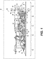
- FIG. 1 a partial, cross-sectional view of an exemplary gas turbine engine 100 is shown with the remaining portion of the gas turbine engine 100 being substantially axisymmetric about a longitudinal axis 140, which also comprises an axis of rotation for the gas turbine engine 100.
- the gas turbine engine 100 is an annular multi-spool turbofan gas turbine jet engine within an aircraft 99, although other arrangements and uses may be provided.
- the gas turbine engine 100 includes a frangible strut 200, which is coupled between or connects an exhaust guide vane 126 of an engine core 104 with an outer bypass duct 106.
- the frangible strut 200 includes an end that is frangible to reduce a load path between the engine core 104 and the outer bypass duct 106.
- loads encountered by the outer bypass duct 106 are reduced, which prolongs a life of the outer bypass duct 106, and components coupled to the outer bypass duct 106, such as components associated with a thrust reverser assembly (not shown).
- the frangible strut 200 also reduces loads induced on mounts that connect the gas turbine engine 100 to the aircraft 99.
- the gas turbine engine 100 includes a fan section 112, a compressor section 114, a combustor section 116, a turbine section 118, and an exhaust section 120.
- the fan section 112 includes a fan 122 mounted on a rotor 124 that draws air into the gas turbine engine 100 and accelerates it. A fraction of the accelerated air exhausted from the fan 122 is directed through the outer bypass duct 106 and the remaining fraction of air exhausted from the fan 122 is directed into the compressor section 114.
- the outer bypass duct 106 is generally defined by an outer casing 128 that is spaced apart from and surrounds the exhaust guide vane 126. As will be discussed, the frangible strut 200 generally extends from the exhaust guide vane 126 to the outer casing 128 of the outer bypass duct 106.
- the compressor section 114 includes one or more compressors 130.
- the number of compressors in the compressor section 114 and the configuration thereof may vary.
- the one or more compressors 130 sequentially raise the pressure of the air and direct a majority of the high pressure air into the combustor section 116.
- a fraction of the compressed air bypasses the combustor section 116 and is used to cool, among other components, turbine blades in the turbine section 118.
- the high pressure air is mixed with fuel, which is combusted.
- the high-temperature combustion air or combustive gas flow is directed into the turbine section 118.
- the turbine section 118 includes one or more turbines 134 disposed in axial flow series. It will be appreciated that the number of turbines, and/or the configurations thereof, may vary.
- the combustive gas expands through and rotates the turbines 134.
- the combustive gas flow then exits turbine section 118 for mixture with the cooler bypass airflow from the outer bypass duct 106 and is ultimately discharged from gas turbine engine 100 through exhaust section 120.
- the turbines 134 in the turbine section 118, the compressors 130 in the compressor section 114 and the fan 122 are mechanically linked by one or more shafts or spools.
- the turbine rotors contained within a high pressure (HP) turbine stage 136 may be rotationally fixed to the compressors 130 contained within compressor section 114 by a HP shaft
- the turbines 134 contained within a low pressure (LP) turbine stage 138 may be rotationally fixed to the rotor 124 of the fan 122 by a coaxial LP shaft.
- gas turbine engine 100 may be a single spool engine or a multi-spool engine containing more than two coaxial shafts.
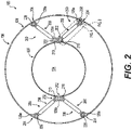
- FIG. 2 a cross-sectional schematic front view of a portion of the gas turbine engine 100 is shown.
- four frangible struts 200 are employed to couple or connect the exhaust guide vane 126 of the engine core 104 with the outer bypass duct 106.
- the location of the frangible struts 200 in FIG. 2 is merely exemplary, as the frangible struts 200 may be positioned at any desired location to couple the engine core 104 to the outer bypass duct 106.
- the number of frangible struts 200 is merely exemplary, as any number of frangible struts 200 may be employed depending upon the size of the engine core 104, for example.
- each of the frangible struts 200 is coupled to the exhaust guide vane 126, which surrounds and is coupled to the engine core 104, and the outer casing 128 of the outer bypass duct 106.
- Each of the frangible struts 200 have a first end 202 and an opposite second end 204, with a body 206 interconnecting the first end 202 and the second end 204.
- the first end 202 is coupled to a first structure of the gas turbine engine 100, which in this example is the exhaust guide vane 126 of the engine core 104
- the second end 204 is coupled to a second structure of the gas turbine engine 100, which in this example, is the outer casing 128 of the outer bypass duct 106.
- the exhaust guide vane 126 includes a plurality of mounting lugs 126a, which are each coupled to the first end 202 of a respective one of the frangible struts 200.
- the exhaust guide vane 126 includes two mounting lugs 126a, which define a pair of bores for coupling to the first end 202 of a pair of the frangible struts 200.
- the outer casing 128 includes a plurality of mounting lugs 128a, which are each coupled to the second end 204 of a respective one of the frangible struts 200.
- the outer casing 128 includes four mounting lugs 128a, which each define a bore for coupling to the second end 204 of the four frangible struts 200.
- the shape and the location of each of the mounting lugs 126a, 128a are merely exemplary, as the mounting lugs 126a, 128a may have any desired shape and may be positioned at any desired location to enable the coupling of the exhaust guide vane 126 to the outer casing 128 by the plurality of frangible struts 200.
- each of the frangible struts 200 is the same, only one of the frangible struts 200 will be described in detail herein for ease of description.
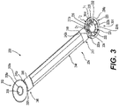
- the frangible strut 200 is shown in greater detail.
- the frangible strut 200 is composed of a metal or metal alloy, including, but not limited to steel, nickel alloy, aluminum and titanium.
- the frangible strut 200 may be composed of a polymer-based material, including, but not limited to Para-aramids, Polyamide 11 & 12, and copolyamide.
- the frangible strut 200 is an integral component, and is formed through any suitable process, including, but not limited to, forging, casting, direct metal laser sintering (DMLS), laser powder bed fusion (L-PBF), electron powder bed fusion (E-PBF), electron beam melting (EBM), etc.
- DMLS direct metal laser sintering
- L-PBF laser powder bed fusion
- E-PBF electron powder bed fusion
- EBM electron beam melting
- the first end 202 is integrally formed with, one-piece or monolithic with the body 206.
- the first end 202 is substantially annular or disc-shaped, and has a thickness that is less than a thickness of the body 206. The reduced thickness of the first end 202 assists in coupling the first end 202 to the engine core 104.
- the first end 202 defines a first bore 208.
- the first bore 208 receives a fastening device, for example a mechanical fastener, such as a bolt 210 ( FIG. 2 ), for coupling the first end 202 to the respective mounting lug 126a of the exhaust guide vane 126. It should be noted that the use of the bolt 210 ( FIG. 2 ), for coupling the first end 202 to the respective mounting lug 126a of the exhaust guide vane 126. It should be noted that the use of the bolt 210 ( FIG.
- the first end 202 is generally solid between an inner perimeter or inner circumference 208a defined by the first bore 208 and an outer perimeter or outer circumference 202a.
- a portion 202b of the outer circumference 202a of the first end 202 is coupled to or integrally formed with the body 206.
- the second end 204 is also integrally formed with, one-piece or monolithic with the body 206.
- the second end 204 is substantially annular or disc-shaped, and has a thickness that is less than the thickness of the body 206. The reduced thickness of the second end 204 assists in coupling the second end 204 to the outer bypass duct 106.
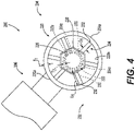
- the second end 204 includes an outer portion 220, an inner portion 222 and a plurality of frangible members 224.
- the outer portion 220 defines an outer perimeter or outer circumference 204a of the second end 204.
- a portion 220a of the outer circumference 204a of the outer portion 220 is coupled to or integrally formed with the body 206.
- the outer portion 220 is coaxial with the inner portion 222, circumscribes the inner portion 222 and is spaced radially apart from the inner portion 222.
- the outer portion 220 has a thickness T1.
- the thickness T1 is less than a thickness T2 of the inner portion 222.
- the thickness T1 retains the outer portion 220 on the inner portion 222 when one or more of the frangible members 224 have broken or fractured.
- the outer portion 220 remains coupled to the outer bypass duct 106.
- the inner portion 222 is substantially annular, and defines both an inner perimeter or an inner circumference 204b of the second end 204, and an outer surface 222a of the inner portion 222 defines an intermediate perimeter or intermediate circumference 204c of the second end 204.
- the inner portion 222 defines a second bore 226.
- the second bore 226 receives a fastening device, for example a mechanical fastener, such as a second bolt 228, for coupling the second end 204 to the respective mounting lug 128a of the outer casing 128 of the outer bypass duct 106 ( FIG. 2 ).
- the inner portion 222 is configured to receive a fastening device, for example a mechanical fastener, such as the second bolt 228, to couple the second end 204 to the outer casing 128 of the outer bypass duct 106 ( FIG. 2 ).
- a fastening device for example a mechanical fastener, such as the second bolt 228, to couple the second end 204 to the outer casing 128 of the outer bypass duct 106 ( FIG. 2 ).
- a fastening device for example a mechanical fastener, such as the second bolt 228, to couple the second end 204 to the outer casing 128 of the outer bypass duct 106 ( FIG. 2 ).
- a mechanical fastener such as the second bolt 228, to couple the second end 204 to the outer casing 128 of the outer bypass duct 106 ( FIG. 2 ).
- the second bore 226 defines the inner perimeter or inner circumference 204b of the second end 204.
- the frangible members 224 space the inner portion 222 apart from the outer portion 220
- the frangible members 224 interconnect the inner portion 222 and the outer portion 220, and are each integrally formed with the inner portion 222 and the outer portion 220. Generally, the frangible members 224 are spaced apart about the intermediate circumference 204c defined by the outer surface 222a of the inner portion 222, and extend from the outer surface 222a of the inner portion 222 to an inner surface 220b of the outer portion 220. It should be noted that while the second end 204 is illustrated herein as having six frangible members 224, the second end 204 may include any number of frangible members 224. In one example, each of the frangible members 224 comprises a solid spoke or cylinder, which extends radially between the inner portion 222 and the outer portion 220.
- Each of the frangible members 224 has a first member end 230 and an opposite second member end 232, with a length L1 defined between the first member end 230 and the second member end 232.
- the first member end 230 is coupled to or integrally formed with the inner portion 222
- the second member end 232 is coupled to or integrally formed with the outer portion 220.
- Each of the frangible members 224 also have a diameter D1, which is predefined to enable each of the frangible members 224 to break or fracture at a pre-determined threshold force.
- the frangible members 224 remain in a first, intact state during a first, normal operating state of the gas turbine engine 100 ( FIG. 2 ), and the frangible members 224 are in a second, fractured state in which the frangible members 224 are broken during a second operating state of the gas turbine engine 100 ( FIG. 5 ).
- the second operating state of the gas turbine engine 100 is an operating state other than a normal operating state in which an unexpected load is generated within the engine core 104, for example.
- each of the frangible members 224 may have the diameter D1 of about 0.15 inches (in.), and are each configured to break or fracture when subjected to a force greater than the pre-defined threshold force of approximately 6000 pounds-force (lbf) of tension or compression along the frangible strut 200.
- the pre-defined threshold force is merely an example, as the pre-defined threshold force may vary based on the size of the gas turbine engine 100 or the particular application for the frangible strut 200.
- the breaking or fracturing of one or more of the frangible members 224 releases the inner portion 222 from the outer portion 220, which substantially removes a load path between the inner portion 222 and the outer portion 220, and reduces a load acting on the outer bypass duct 106.
- the body 206 interconnects the first end 202 and the second end 204.
- the body 206 includes a first body end 240, an opposite second body end 242 and a main body section 244.
- the first body end 240 includes a pair of opposed flat surfaces 246, which transition the body 206 to the first end 202.
- a terminal end 240a of the first body end 240 is integrally formed with or coupled to the portion 202b of the outer circumference 202a of the first end 202.
- the second body end 242 includes a second pair of opposed flat surfaces 248, which transition the body 206 to the second end 204.
- a terminal end 242a of the second body end 242 is integrally formed with or coupled to the portion 220a of the outer circumference 204a of the second end 204.
- the main body section 244 is cylindrical and interconnects the first body end 240 with the second body end 242.
- the main body section 244 is substantially solid; however, the main body section 244 may be hollow.
- each of the frangible struts 200 formed with reference to FIG. 2 , the first end 202 of each of the frangible struts 200 is coupled to the first structure or the mounting lug 126a of the exhaust guide vane 126 of the engine core 104 of the gas turbine engine 100 via the bolt 210.
- the second end 204 of each of the frangible struts 200 is coupled to the second structure or the mounting lug 128a of the outer casing 128 of the outer bypass duct 106 of the gas turbine engine 100 via the second bolt 228.
- the frangible struts 200 coupled between the engine core 104 and the outer bypass duct 106 of the gas turbine engine 100, in the first, normal operating state of the gas turbine engine 100, the frangible struts 200 reduce rubbing and maintain clearances between rotating components within the engine core 104 and the static structure of the engine core 104, along with maintaining clearances between the engine core 104 and the outer bypass duct 106, which increases performance of the gas turbine engine 100.
- the frangible members 224 are in the first, intact state.
- the frangible members 224 of each of the second ends 204 fracture or break, releasing the outer portion 220 from the inner portion 222 of the respective frangible strut 200.
- the thickness T1 FIG.
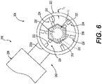
- each of the frangible members 224 has fractured or broken at breaks 250, thereby releasing the outer portion 220 from the inner portion 222.
- the breaks 250 in the frangible members 224 shown in FIG. 6 are merely exemplary, as each of the frangible members 224 may fracture or break at any point along the length L1 of each of the frangible members 224.
- the release of the outer portion 220 from the inner portion 222 substantially removes a load path between the engine core 104 ( FIG. 5 ) and the outer bypass duct 106 ( FIG. 5 ), and also reduces forces acting on the outer bypass duct 106 ( FIG. 5 ).
- the frangible members 224 may be configured differently to release the outer portion 220 from the inner portion 222 during the second operating state of the gas turbine engine 100.
- a plurality of frangible members 324 for use with the second end 204 of the frangible strut 200 are shown.
- the frangible members 324 interconnect the inner portion 222 and the outer portion 220, and are each integrally formed with the inner portion 222 and the outer portion 220.
- the frangible members 324 are spaced apart about the intermediate circumference 204c defined by the outer surface 222a of the inner portion 222, and extend from the outer surface 222a of the inner portion 222 to the inner surface 220b of the outer portion 220.
- each of the frangible members 324 comprises a solid S-shaped body, which extends radially between the inner portion 222 and the outer portion 220.
- each of the frangible members 324 is curved.
- Each of the frangible members 324 has a first member end 330 and an opposite second member end 332, with an overall length L2 defined between the first member end 330 and the second member end 332.
- the first member end 330 is coupled to or integrally formed with the inner portion 222, and the second member end 332 is coupled to or integrally formed with the outer portion 220.
- Each of the frangible members 324 also have a thickness T3, which is predefined to enable each of the frangible members 324 to break or fracture at a pre-determined threshold force.
- each of the frangible members 324 may have the thickness T3 of about 0.1 inches (in.), and are each configured to break or fracture when subjected to a force greater than the pre-defined threshold force of approximately 6000 pounds-force (lbf) of tension or compression along the frangible strut 200.
- the pre-defined threshold force is merely an example, as the pre-defined threshold force may vary based on the size of the gas turbine engine 100 or the particular application for the frangible strut 200.
- the breaking or fracturing of one or more of the frangible members 324 releases the inner portion 222 from the outer portion 220, which substantially removes a load path between the engine core 104 ( FIG. 5 ) and the outer bypass duct 106 ( FIG. 5 ), and reduces a load acting on the outer bypass duct 106 ( FIG. 5 ).
- each of the frangible struts 200 formed with the second end 204 including the plurality of frangible members 324 the first end 202 of each of the frangible struts 200 is coupled to the first structure or the mounting lugs 126a of the exhaust guide vane 126 of the engine core 104 of the gas turbine engine 100 via the bolt 210 ( FIG. 2 ).
- the second end 204 of each of the frangible struts 200 is coupled to the second structure or the mounting lugs 128a of the outer casing 128 of the outer bypass duct 106 of the gas turbine engine 100 via the second bolt 228.
- the frangible struts 200 reduce rubbing and maintain clearances between rotating components within the engine core 104 and the static structure of the engine core 104, along with maintaining clearances between the engine core 104 and the outer bypass duct 106 ( FIG. 2 ), which increases performance of the gas turbine engine 100.
- the frangible members 324 are in the first, intact state.
- the frangible members 324 of each of the second ends 204 fracture or break, releasing the outer portion 220 from the inner portion 222 of the respective frangible strut 200.
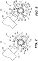
- FIG. 8 a detail view of the second end 204 with the frangible members 324 in the second, fractured state is shown.
- each of the frangible members 324 has fractured or broken at breaks 350, thereby releasing the outer portion 220 from the inner portion 222.
- each of the frangible members 324 may fracture or break at any point along the length L3 of each of the frangible members 324.
- the release of the outer portion 220 from the inner portion 222 substantially removes a load path between the engine core 104 ( FIG. 5 ) and the outer bypass duct 106 ( FIG. 5 ), and also reduces forces acting on the outer bypass duct 106 ( FIG. 5 ).
- thickness T1 of the outer portion 220 may maintain the outer portion 220 disposed about the inner portion 222 after the failure or fracture of the frangible members 324, which maintains the coupling of the outer bypass duct 106 to the engine core 104 while reducing loads that are transferred to the outer bypass duct 106.
- the frangible members 224 may be configured differently to release the outer portion 220 from the inner portion 222 during the second operating state of the gas turbine engine 100.
- a plurality of frangible members 424 for use with the second end 204 of the frangible strut 200 are shown.
- the frangible members 424 interconnect the inner portion 222 and the outer portion 220, and are each integrally formed with the inner portion 222 and the outer portion 220.
- the frangible members 424 are spaced apart about the intermediate circumference 204c defined by the outer surface 222a of the inner portion 222, and extend from the outer surface 222a of the inner portion 222 to the inner surface 220b of the outer portion 220.
- each of the frangible members 424 comprises a solid C-shaped body, which extends radially between the inner portion 222 and the outer portion 220.
- each of the frangible members 424 is curved.
- Each of the frangible members 424 has a first member end 430 and an opposite second member end 432, with a diameter D4 defined between the first member end 430 and the second member end 432.
- the first member end 430 is coupled to or integrally formed with the inner portion 222
- the second member end 432 is coupled to or integrally formed with the outer portion 220.
- Each of the frangible members 424 also have a thickness T4, which is predefined to enable each of the frangible members 424 to break or fracture at a pre-determined threshold force.
- each of the frangible members 424 may have the thickness T4 of about 0.1 inches (in.), and are each configured to break or fracture when subjected to a force greater than the pre-defined threshold force of approximately 6000 pounds-force (lbf) of tension or compression along the frangible strut 200.
- the pre-defined threshold force is merely an example, as the pre-defined threshold force may vary based on the size of the gas turbine engine 100 or the particular application for the frangible strut 200.
- the breaking or fracturing of one or more of the frangible members 424 releases the inner portion 222 from the outer portion 220, which substantially removes a load path between the engine core 104 ( FIG. 5 ) and the outer bypass duct 106 ( FIG. 5 ), and reduces a load acting on the outer bypass duct 106 ( FIG. 5 ).
- each of the frangible struts 200 formed with the second end 204 including the plurality of frangible members 424 the first end 202 of each of the frangible struts 200 is coupled to the first structure or the mounting lugs 126a of the exhaust guide vane 126 of the engine core 104 of the gas turbine engine 100 via the bolt 210 ( FIG. 2 ).
- the second end 204 of each of the frangible struts 200 is coupled to the second structure or the mounting lugs 128a of the outer casing 128 of the outer bypass duct 106 of the gas turbine engine 100 via the second bolt 228.
- the frangible struts 200 reduce rubbing and maintain clearances between rotating components within the engine core 104 and the static structure of the engine core 104, along with maintaining clearances between the engine core 104 and the outer bypass duct 106 ( FIG. 2 ), which increases performance of the gas turbine engine 100.
- the frangible members 424 are in the first, intact state.
- the frangible members 424 of each of the second ends 204 fracture or break, releasing the outer portion 220 from the inner portion 222 of the respective frangible strut 200.
- FIG. 10 a detail view of the second end 204 with the frangible members 424 in the second, fractured state is shown.
- each of the frangible members 424 has fractured or broken at breaks 450, thereby releasing the outer portion 220 from the inner portion 222.
- each of the frangible members 424 may fracture or break at any point between the first member end 430 and the second member end 432 of each of the frangible members 424.
- the release of the outer portion 220 from the inner portion 222 substantially removes a load path between the engine core 104 ( FIG. 5 ) and the outer bypass duct 106 ( FIG. 5 ), and also reduces forces acting on the outer bypass duct 106 ( FIG. 5 ).
- thickness T1 of the outer portion 220 may maintain the outer portion 220 disposed about the inner portion 222 after the failure or fracture of the frangible members 424, which maintains the coupling of the outer bypass duct 106 to the engine core 104 while reducing loads that are transferred to the outer bypass duct 106.
- the frangible members 224 may be configured differently to release the outer portion 220 from the inner portion 222 during the second operating state of the gas turbine engine 100.
- a plurality of frangible members 524 for use with the second end 204 of the frangible strut 200 are shown.
- the frangible members 524 interconnect the inner portion 222 and the outer portion 220, and are each integrally formed with the inner portion 222 and the outer portion 220.
- the frangible members 524 are spaced apart about the intermediate circumference 204c defined by the outer surface 222a of the inner portion 222, and extend from the outer surface 222a of the inner portion 222 to the inner surface 220b of the outer portion 220.
- each of the frangible members 524 comprises a ring, which is defined radially between the inner portion 222 and the outer portion 220.
- Each of the frangible members 524 has a first member end 530 and an opposite second member end 532, with a diameter D5 defined between the first member end 530 and the second member end 532.
- the first member end 530 is coupled to or integrally formed with the inner portion 222
- the second member end 532 is coupled to or integrally formed with the outer portion 220.
- Each of the frangible members 524 also have a thickness T5, which is predefined to enable each of the frangible members 524 to break or fracture at a pre-determined threshold force.
- each of the frangible members 524 may have the thickness T5 of about 0.1 inches (in.), and are each configured to break or fracture when subjected to a force greater than the pre-defined threshold force of approximately 6000 pounds-force (lbf) of tension or compression along the frangible strut 200.
- the pre-defined threshold force is merely an example, as the pre-defined threshold force may vary based on the size of the gas turbine engine 100 or the particular application for the frangible strut 200.
- the breaking or fracturing of one or more of the frangible members 524 releases the inner portion 222 from the outer portion 220, which substantially removes a load path between the engine core 104 ( FIG. 5 ) and the outer bypass duct 106 ( FIG. 5 ), and reduces a load acting on the outer bypass duct 106 ( FIG. 5 ).
- each of the frangible struts 200 formed with the second end 204 including the plurality of frangible members 524 the first end 202 of each of the frangible struts 200 is coupled to the first structure or the mounting lugs 126a of the exhaust guide vane 126 of the engine core 104 of the gas turbine engine 100 via the bolt 210 ( FIG. 2 ).
- the second end 204 of each of the frangible struts 200 is coupled to the second structure or the mounting lugs 128a of the outer casing 128 of the outer bypass duct 106 of the gas turbine engine 100 via the second bolt 228.
- the frangible struts 200 reduce rubbing and maintain clearances between rotating components within the engine core 104 and the static structure of the engine core 104, along with maintaining clearances between the engine core 104 and the outer bypass duct 106 ( FIG. 2 ), which increases performance of the gas turbine engine 100.
- the frangible members 524 are in the first, intact state.
- the frangible members 524 of each of the second ends 204 fracture or break, releasing the outer portion 220 from the inner portion 222 of the respective frangible strut 200.
- FIG. 10 a detail view of the second end 204 with the frangible members 524 in the second, fractured state is shown.
- each of the frangible members 524 has fractured or broken at breaks 550, thereby releasing the outer portion 220 from the inner portion 222.
- each of the frangible members 524 may fracture or break at any point about the circumference of each of the frangible members 524.
- the release of the outer portion 220 from the inner portion 222 substantially removes a load path between the engine core 104 ( FIG. 5 ) and the outer bypass duct 106 ( FIG. 5 ), and also reduces forces acting on the outer bypass duct 106 ( FIG. 5 ).
- thickness T1 of the outer portion 220 may maintain the outer portion 220 disposed about the inner portion 222 after the failure or fracture of the frangible members 524, which maintains the coupling of the outer bypass duct 106 to the engine core 104 while reducing loads that are transferred to the outer bypass duct 106.
- the frangible strut 200 may be configured differently to substantially remove the load path between the engine core 104 and the outer bypass duct 106 ( FIG. 1 ) during the second operating state of the gas turbine engine 100.
- FIG. 13 a cross-sectional schematic front view of a portion of the gas turbine engine 100 is shown.
- four frangible struts 600 are employed to couple or connect the exhaust guide vane 126 of the engine core 104 with the outer bypass duct 106. It should be noted that the location of the frangible struts 600 in FIG.
- each of the frangible struts 600 is coupled to the exhaust guide vane 126, which surrounds and is coupled to the engine core 104, and the outer casing 128 of the outer bypass duct 106.
- Each of the frangible struts 600 have the first end 202 and an opposite second end 604, with a body 606 interconnecting the first end 202 and the second end 604.
- the first end 202 is coupled to the first structure of the gas turbine engine 100, which in this example is a respective one of the mounting lugs 126a of the exhaust guide vane 126 of the engine core 104
- the second end 604 is coupled to the second structure of the gas turbine engine 100, which in this example, is a respective one of the mounting lugs 128a of the outer casing 128 of the outer bypass duct 106.
- each of the frangible struts 600 is the same, only one of the frangible struts 600 will be described in detail herein for ease of description.
- the frangible strut 600 is composed of a metal or metal alloy, including, but not limited to steel, nickel alloy, aluminum and titanium. In other embodiments, the frangible strut 600 may be composed of a polymer-based material, including, but not limited to Para-aramids, Polyamide 11 & 12, and copolyamide. In one example, the frangible strut 600 is an integral component, and is formed through any suitable process, including, but not limited to, forging, casting, direct metal laser sintering (DMLS), laser powder bed fusion (L-PBF), electron powder bed fusion (E-PBF), electron beam melting (EBM), etc.
- DMLS direct metal laser sintering
- L-PBF laser powder bed fusion
- E-PBF electron powder bed fusion
- EBM electron beam melting
- first end 202 and the second end 604 are each integrally formed with, one-piece or monolithic with the body 606.
- the portion 202b of the outer circumference 202a of the first end 202 is coupled to or integrally formed with the body 606.
- first end 202 and the second end 604 are substantially the same.
- the second end 604 is substantially annular or disc-shaped, and has a thickness that is less than a thickness of the body 606. The reduced thickness of the second end 604 assists in coupling the second end 604 to outer casing 128 of the outer bypass duct 106.
- the second end 604 defines a second bore 608.
- the second bore 608 receives a fastening device, for example, a mechanical fastener, such as a second bolt 610, for coupling the second end 604 to a respective one of the mounting lugs 128a of the outer casing 128 of the outer bypass duct 106.
- a mechanical fastener such as a second bolt 610
- the second end 604 is generally solid between an inner perimeter or inner circumference 608a defined by the second bore 608 and an outer perimeter or outer circumference 604a.
- a portion 604b of the outer circumference 604a of the second end 604 is coupled to or integrally formed with the body 606.
- the body 606 interconnects the first end 202 and the second end 604.
- the body 606 includes the first body end 240, the opposite second body end 242 and a main body section 644.
- the first body end 240 includes the pair of opposed flat surfaces 246, which transition the body 606 to the first end 202.
- the second body end 242 includes the second pair of opposed flat surfaces 248, which transition the body 206 to the second end 604.
- the main body section 644 of the body 606 includes a first main body portion 646, a second main body portion 648 and a frangible portion 650 defined between the first main body portion 646 and the second main body portion 648.
- the first main body portion 646 is substantially cylindrical, and is substantially solid.
- the first main body portion 646 is defined between and coupled to the first body end 240 and the frangible portion 650.
- the first main body portion 646 has a first end 646a coupled to or integrally formed with the first body end 240, and an opposite second end 646b coupled to or integrally formed with the frangible portion 650.
- the second main body portion 648 is substantially cylindrical, and is substantially solid.
- the second main body portion 648 is defined between and coupled to the second body end 242 and the frangible portion 650.
- the second main body portion 648 has a first end 648a coupled to or integrally formed with the second body end 242, and an opposite second end 648b coupled to or integrally formed with the frangible portion 650.
- the frangible portion 650 interconnects the first main body portion 646 and the second main body portion 648.
- the frangible portion 650 is integrally formed with the first main body portion 646 and the second main body portion 648.
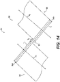
- the frangible portion 650 is shown in greater detail.
- the first main body portion 646 extends along a first axis A1
- the second main body portion 648 extends along a second axis A2.
- the first axis A1 is different than and substantially parallel to the second axis A2, and thus, the second end 646b of the first main body portion 646 is offset from the second end 648b of the second main body portion 648.
- the frangible portion 650 is defined between the second end 646b of the first main body portion 646 and the second end 648b of the second main body portion 648 to interconnect the second ends 646b, 648b.
- the frangible portion 650 comprises a bar that extends between the second end 646b of the first main body portion 646 and the second end 648b of the second main body portion 648; however, the frangible portion 650 may have any desired shape.
- the frangible portion 650 has a thickness T6, which is less than a thickness T7 of each of the second ends 646b, 648b.
- the thickness T6 is predefined to enable the frangible portion 650 to break or fracture at a pre-determined threshold force.
- the frangible portion 650 remains in a first, intact state during a first, normal operating state of the gas turbine engine 100 ( FIG. 13 ), and the frangible portion 650 is in a second, fractured state in which the frangible portion 650 is broken during the second operating state of the gas turbine engine 100 ( FIG. 15 ).
- the frangible portion 650 may have the thickness T6 of about 0.25 inches (in.), and is configured to break or fracture when subjected to a force greater than the pre-defined threshold force of approximately 6000 pounds-force (lbf) of tension or compression along the frangible strut 600.
- the pre-defined threshold force is merely an example, as the pre-defined threshold force may vary based on the size of the gas turbine engine 100 or the particular application for the frangible strut 600.
- the breaking or fracturing of the frangible portion 650 releases the first main body portion 646 from the second main body portion 648, which substantially removes a load path between the engine core 104 and the outer bypass duct 106, and reduces a load acting on the outer bypass duct 106.
- each of the frangible struts 600 the first end 202 of each of the frangible struts 600 is coupled to the first structure or the mounting lugs 126a of the exhaust guide vane 126 of the engine core 104 of the gas turbine engine 100 via the bolt 210.
- the second end 604 of each of the frangible struts 600 is coupled to the second structure or the mounting lugs 128a of the outer casing 128 of the outer bypass duct 106 of the gas turbine engine 100 via the second bolt 610.
- the frangible struts 600 coupled between the engine core 104 and the outer bypass duct 106 of the gas turbine engine 100, in the first, normal operating state of the gas turbine engine 100, the frangible struts 600 reduce rubbing and maintain clearances between rotating components within the engine core 104 and the static structure of the engine core 104, along with maintaining clearances between the engine core 104 and the outer bypass duct 106, which increases performance of the gas turbine engine 100.
- the frangible portion 650 is in the first, intact state.
- the frangible portion 650 fractures or breaks, releasing the first main body portion 646 from the second main body portion 648 of the respective frangible strut 600.
- FIG. 15 is a detail view of the body 606 with the frangible portion 650 in the second, fractured state.
- the frangible portion 650 has fractured or broken at break 660, thereby releasing the first main body portion 646 from the second main body portion 648.
- the break 660 in the frangible portion 650 shown in FIG. 15 is merely exemplary, as the frangible portion 650 may fracture or break at any point along the frangible portion 650 between the second end 646b of the first main body portion 646 and the second end 648b of the second main body portion 648.
- the release of the first main body portion 646 from the second main body portion 648 substantially removes a load path between the engine core 104 ( FIG. 13 ) and the outer bypass duct 106 ( FIG. 13 ), and also reduces forces acting on the outer bypass duct 106 ( FIG. 13 ).
- the frangible portion 650 may be configured differently to release the first main body portion 646 from the second main body portion 648 during the second operating state of the gas turbine engine 100.
- a frangible portion 750 for use with the body 606 of the frangible strut 600 is shown.
- the frangible portion 750 interconnects the first main body portion 646 and the second main body portion 648.
- the frangible portion 750 is integrally formed with the first main body portion 646 and the second main body portion 648.
- FIG. 17 the frangible portion 750 is shown in greater detail.
- the first main body portion 646 extends along the first axis A1
- the second main body portion 648 extends along the second axis A2 such that the second end 646b of the first main body portion 646 is offset from the second end 648b of the second main body portion 648.
- the frangible portion 750 is defined between the second end 646b of the first main body portion 646 and the second end 648b of the second main body portion 648 to interconnect the second ends 646b, 648b.
- the frangible portion 750 comprises a first bar 752, a second bar 754 and a plurality of frangible members 756.
- the first bar 752 is coupled to or integrally formed with the second end 646b of the first main body portion 646, and extends from the second end 646b of the first main body portion 646 toward the second end 648b.
- the second bar 754 is coupled to or integrally formed with the second end 648b of the second main body portion 648, and extends from the second end 648b of the second main body portion 648 toward the second end 646b.
- the first bar 752 and the second bar 754 are substantially parallel.
- the first bar 752 is spaced apart from the second bar 754 by the plurality of frangible members 756.
- the frangible members 756 interconnect the first bar 752 and the second bar 754, and are each integrally formed with the first bar 752 and the second bar 754. Generally, the frangible members 756 are spaced apart between a first end 750a of the frangible portion 750 and a second end 750b of the frangible portion 750, and extend from an inner surface 752a of the first bar 752 to an inner surface 754a of the second bar 754. It should be noted that while the frangible portion 750 is illustrated herein as having five frangible members 756, the frangible portion 750 may include any number of frangible members 756.
- each of the frangible members 756 comprises a solid S-shaped body, which extends between the first bar 752 and the second bar 754.
- each of the frangible members 756 is curved.
- Each of the frangible members 756 has a first member end 758 and an opposite second member end 760, with an overall length L7 defined between the first member end 758 and the second member end 760.
- the first member end 758 is coupled to or integrally formed with the first bar 752, and the second member end 760 is coupled to or integrally formed with the second bar 754.
- Each of the frangible members 756 also have a thickness T8, which is predefined to enable each of the frangible members 756 to break or fracture at a pre-determined threshold force.
- each of the frangible members 756 may have the thickness T8 of about 0.15 inches (in.), and are each configured to break or fracture when subjected to a force greater than the pre-defined threshold force of approximately 6000 pounds-force (lbf) of tension or compression along the frangible strut 600.
- the pre-defined threshold force is merely an example, as the pre-defined threshold force may vary based on the size of the gas turbine engine 100 or the particular application for the frangible strut 600.
- the breaking or fracturing of one or more of the frangible members 756 releases the first bar 752 and the first main body portion 646 from the second bar 754 and the second main body portion 648, which substantially removes a load path between the engine core 104 and the outer bypass duct 106, and reduces a load acting on the outer bypass duct 106.
- each of the frangible struts 600 the first end 202 of each of the frangible struts 600 is coupled to the first structure or the mounting lugs 126a of the exhaust guide vane 126 of the engine core 104 of the gas turbine engine 100 via the bolt 210.
- the second end 604 of each of the frangible struts 600 is coupled to the second structure or the mounting lugs 128a of the outer casing 128 of the outer bypass duct 106 of the gas turbine engine 100 via the second bolt 610.
- the frangible struts 600 coupled between the engine core 104 and the outer bypass duct 106 of the gas turbine engine 100, in the first, normal operating state of the gas turbine engine 100, the frangible struts 600 reduce rubbing and maintain clearances between rotating components within the engine core 104 and the static structure of the engine core 104, along with maintaining clearances between the engine core 104 and the outer bypass duct 106, which increases performance of the gas turbine engine 100.
- the frangible portion 750 is in the first, intact state.
- the frangible members 756 of the frangible portion 750 fracture or break, releasing the first main body portion 646 from the second main body portion 648 of the respective frangible strut 600.
- FIG. 18 is a detail view of the body 606 with the frangible portion 750 in the second, fractured state.
- each of the frangible members 756 is fractured or broken at break 770, thereby releasing the first main body portion 646 from the second main body portion 648.
- the breaks 770 in the frangible members 756 shown in FIG. 18 are merely exemplary, as the frangible members 756 may fracture or break at any point along the respective frangible member 756 between the first member end 758 and the second member end 760.
- the release of the first main body portion 646 from the second main body portion 648 substantially removes a load path between the engine core 104 ( FIG. 16 ) and the outer bypass duct 106 ( FIG. 16 ), and also reduces forces acting on the outer bypass duct 106 ( FIG. 16 ).
- the frangible portion 650 may be configured differently to release the first main body portion 646 from the second main body portion 648 during the second operating state of the gas turbine engine 100.
- FIG. 19 which is not according to the Claims, a frangible portion 850 for use with the body 606 of the frangible strut 600 is shown.
- the frangible portion 850 interconnects the first main body portion 646 and the second main body portion 648.
- the frangible portion 850 is integrally formed with the first main body portion 646 and the second main body portion 648.
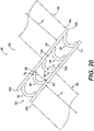
- FIG. 20 the frangible portion 850 is shown in greater detail.
- the first main body portion 646 extends along the first axis A1
- the second main body portion 648 extends along the second axis A2 such that the second end 646b of the first main body portion 646 is offset from the second end 648b of the second main body portion 648.
- the frangible portion 850 is defined between the second end 646b of the first main body portion 646 and the second end 648b of the second main body portion 648 to interconnect the second ends 646b, 648b.
- the frangible portion 850 comprises the first bar 752, the second bar 754 and a plurality of frangible members 856.
- the first bar 752 is coupled to or integrally formed with the second end 646b of the first main body portion 646, and the second bar 754 is coupled to or integrally formed with the second end 648b of the second main body portion 648.
- the first bar 752 is spaced apart from the second bar 754 by the plurality of frangible members 856.
- the frangible members 856 interconnect the first bar 752 and the second bar 754, and are each integrally formed with the first bar 752 and the second bar 754. Generally, the frangible members 856 are spaced apart between a first end 850a of the frangible portion 850 and a second end 850b of the frangible portion 850, and extend from the inner surface 752a of the first bar 752 to the inner surface 754a of the second bar 754. It should be noted that while the frangible portion 850 is illustrated herein as having five frangible members 856, the frangible portion 850 may include any number of frangible members 856.
- each of the frangible members 856 comprises a solid C-shaped body, which extends between the between the first bar 752 and the second bar 754.
- each of the frangible members 856 is curved.
- Each of the frangible members 856 has a first member end 858 and an opposite second member end 860, with a diameter D8 defined between the first member end 858 and the second member end 860.
- the first member end 858 is coupled to or integrally formed with the first bar 752, and the second member end 860 is coupled to or integrally formed with the second bar 754.
- Each of the frangible members 856 also have a thickness T9, which is predefined to enable each of the frangible members 856 to break or fracture at a pre-determined threshold force.
- each of the frangible members 856 may have the thickness T9 of about 0.15 inches (in.), and are each configured to break or fracture when subjected to a force greater than the pre-defined threshold force of approximately 6000 pounds-force (lbf) of tension or compression along the frangible strut 600.
- the pre-defined threshold force is merely an example, as the pre-defined threshold force may vary based on the size of the gas turbine engine 100 or the particular application for the frangible strut 600.
- the breaking or fracturing of one or more of the frangible members 856 releases the first bar 752 and the first main body portion 646 from the second bar 754 and the second main body portion 648, which substantially removes a load path between the engine core 104 and the outer bypass duct 106, and reduces a load acting on the outer bypass duct 106.
- each of the frangible struts 600 the first end 202 of each of the frangible struts 600 is coupled to the first structure or the mounting lugs 126a of the exhaust guide vane 126 of the engine core 104 of the gas turbine engine 100 via the bolt 210.
- the second end 604 of each of the frangible struts 600 is coupled to the second structure or the mounting lugs 128a of the outer casing 128 of the outer bypass duct 106 of the gas turbine engine 100 via the second bolt 610.
- the frangible struts 600 coupled between the engine core 104 and the outer bypass duct 106 of the gas turbine engine 100, in the first, normal operating state of the gas turbine engine 100, the frangible struts 600 reduce rubbing and maintain clearances between rotating components within the engine core 104 and the static structure of the engine core 104, along with maintaining clearances between the engine core 104 and the outer bypass duct 106, which increases performance of the gas turbine engine 100.
- the frangible portion 850 is in the first, intact state.
- the frangible members 856 of the frangible portion 850 fracture or break, releasing the first main body portion 646 from the second main body portion 648 of the respective frangible strut 600.
- FIG. 21 is a detail view of the body 606 with the frangible portion 850 in the second, fractured state.
- each of the frangible members 856 is fractured or broken at break 870, thereby releasing the first main body portion 646 from the second main body portion 648.
- the breaks 870 in the frangible members 856 shown in FIG. 21 are merely exemplary, as the frangible members 856 may fracture or break at any point along the respective frangible member 856 between the first member end 858 and the second member end 860.
- the release of the first main body portion 646 from the second main body portion 648 substantially removes a load path between the engine core 104 ( FIG. 19 ) and the outer bypass duct 106 ( FIG. 19 ), and also reduces forces acting on the outer bypass duct 106 ( FIG. 19 ).
- the frangible portion 650 may be configured differently to release the first main body portion 646 from the second main body portion 648 during the second operating state of the gas turbine engine 100.
- a frangible portion 950 for use with the body 606 of the frangible strut 600 is shown.
- the frangible portion 950 interconnects the first main body portion 646 and the second main body portion 648.
- the frangible portion 950 is integrally formed with the first main body portion 646 and the second main body portion 648.
- FIG. 23 which is not according to the Claims, the frangible portion 950 is shown in greater detail.
- the first main body portion 646 extends along the first axis A1
- the second main body portion 648 extends along the second axis A2 such that the second end 646b of the first main body portion 646 is offset from the second end 648b of the second main body portion 648.
- the frangible portion 950 is defined between the second end 646b of the first main body portion 646 and the second end 648b of the second main body portion 648 to interconnect the second ends 646b, 648b.
- the frangible portion 950 comprises the first bar 752, the second bar 754 and a plurality of frangible members 956.
- the first bar 752 is coupled to or integrally formed with the second end 646b of the first main body portion 646, and the second bar 754 is coupled to or integrally formed with the second end 648b of the second main body portion 648.
- the first bar 752 is spaced apart from the second bar 754 by the plurality of frangible members 956.
- the frangible members 956 interconnect the first bar 752 and the second bar 754, and are each integrally formed with the first bar 752 and the second bar 754. Generally, the frangible members 956 are spaced apart between a first end 950a of the frangible portion 950 and a second end 950b of the frangible portion 950, and extend from the inner surface 752a of the first bar 752 to the inner surface 754a of the second bar 754. It should be noted that while the frangible portion 950 is illustrated herein as having three frangible members 956, the frangible portion 950 may include any number of frangible members 956. In one example, each of the frangible members 956 comprises a ring, which is defined between the first bar 752 and the second bar 754.
- Each of the frangible members 956 has a first member end 958 and an opposite second member end 960, with a diameter D9 defined between the first member end 958 and the second member end 960.
- the first member end 958 is coupled to or integrally formed with the first bar 752
- the second member end 960 is coupled to or integrally formed with the second bar 754.
- Each of the frangible members 956 also have a thickness T10, which is predefined to enable each of the frangible members 956 to break or fracture at a pre-determined threshold force.
- each of the frangible members 956 may have the thickness T10 of about 0.15 inches (in.), and are each configured to break or fracture when subjected to a force greater than the pre-defined threshold force of approximately 6000 pounds-force (lbf) of tension or compression along the frangible strut 600.
- the pre-defined threshold force is merely an example, as the pre-defined threshold force may vary based on the size of the gas turbine engine 100 or the particular application for the frangible strut 600.
- the breaking or fracturing of one or more of the frangible members 956 releases the first bar 752 and the first main body portion 646 from the second bar 754 and the second main body portion 648, which substantially removes a load path between the engine core 104 and the outer bypass duct 106, and reduces a load acting on the outer bypass duct 106.
- each of the frangible struts 600 the first end 202 of each of the frangible struts 600 is coupled to the first structure or the mounting lugs 126a of the exhaust guide vane 126 of the engine core 104 of the gas turbine engine 100 via the bolt 210.
- the second end 604 of each of the frangible struts 600 is coupled to the second structure or the mounting lugs 128a of the outer casing 128 of the outer bypass duct 106 of the gas turbine engine 100 via the second bolt 610.
- the frangible struts 600 coupled between the engine core 104 and the outer bypass duct 106 of the gas turbine engine 100, in the first, normal operating state of the gas turbine engine 100, the frangible struts 600 reduce rubbing and maintain clearances between rotating components within the engine core 104 and the static structure of the engine core 104, along with maintaining clearances between the engine core 104 and the outer bypass duct 106, which increases performance of the gas turbine engine 100.
- the frangible portion 950 is in the first, intact state.
- the frangible members 956 of the frangible portion 950 fracture or break, releasing the first main body portion 646 from the second main body portion 648 of the respective frangible strut 600.
- FIG. 24 is a detail view of the body 606 with the frangible portion 950 in the second, fractured state.
- each of the frangible members 956 is fractured or broken at breaks 970, thereby releasing the first main body portion 646 from the second main body portion 648.
- the breaks 970 in the frangible members 956 shown in FIG. 24 are merely exemplary, as the frangible members 956 may fracture or break at any point along the respective frangible member 956 between the first member end 958 and the second member end 960.
- the release of the first main body portion 646 from the second main body portion 648 substantially removes a load path between the engine core 104 ( FIG. 22 ) and the outer bypass duct 106 ( FIG. 22 ), and also reduces forces acting on the outer bypass duct 106 ( FIG. 22 ).
- the frangible struts 200, 600 are configured to remove a load path between the exhaust guide vane 126 of the engine core 104 and the outer bypass duct 106. By removing this load path, the components coupled to the outer bypass duct 106, such as components associated with a thrust reverser assembly, are subjected to reduced loads when the gas turbine engine 100 ( FIG. 1 ) is in the second operating state, such as when an unexpected load is generated within the engine core 104.
- the frangible struts 200, 600 reduce a shear load acting on a flange of the thrust reverser assembly by about 38%, and reduce a moment load acting on the flange of the thrust reverser assembly by about 40%.
- the frangible struts 200, 600 ensure proper operation of the thrust reverser assembly during the second operating state of the gas turbine engine 100.
- the gas turbine engine 100 may include any number of the frangible struts 200, 600, and may include a combination of the frangible struts 200, 600.
- the gas turbine engine 100 may include one or more of the frangible struts 200, 600 having the frangible members 224, 324, 424, 524 or the frangible portion 650, 750, 850, 950, respectively, and may include one or more struts that do not include the frangible members 224, 324, 424, 524 or the frangible portion 650, 750, 850, 950.
- the orientation of the frangible strut 200 may be reversed, such that the second end 204, including the frangible members 224, 324, 424, 524, is coupled to the exhaust guide vane 126 of the engine core 104.
- frangible strut 600 is shown with the frangible portion 650, 750, 850, 950 defined substantially in a center of the body 606, the frangible portion 650, 750, 850, 950 may be defined in the body 606 at any location between the first end 202 and the second end 604 of the frangible strut 600, and thus, the location illustrated herein for the frangible portion 650, 750, 850, 950 is merely an example.
- the frangible strut 200, 600 is shown and described herein as being composed of a single material, the frangible strut 200, 600 may be composed of multiple materials.
- the second end 204 of the frangible strut 200 may include any combination of the frangible members 224, 324, 424, 524, and the frangible portion 750, 850, 950 of the frangible strut 600 may include any combination of the frangible members 756, 856, 956.
Landscapes
- Engineering & Computer Science (AREA)
- Mechanical Engineering (AREA)
- General Engineering & Computer Science (AREA)
- Chemical & Material Sciences (AREA)
- Combustion & Propulsion (AREA)
- Structures Of Non-Positive Displacement Pumps (AREA)
Description
- The present disclosure generally relates to gas turbine engines, and more particularly relates to a frangible strut for a gas turbine engine.
- Gas turbine engines may be employed to power various devices. For example, a gas turbine engine may be employed to power a mobile platform, such as an aircraft. Generally, gas turbine engines have an engine core, in which gas is combusted to generate a hot combustive gas flow. In certain instances, the gas turbine engine may also include an outer bypass duct, which surrounds the engine core. The outer bypass duct may provide cooling air for components of the gas turbine engine, and may support other components associated with the gas turbine engine, such as components associated with a thrust reverser assembly. In certain instances, a connecting structure may be provided to connect the engine core with the outer bypass duct to maintain tighter rotor-structure clearances. In these instances, a load generated by the engine core may be directly transferred to the outer bypass duct by the connecting structure. The transferred loads or forces may affect the operation of the outer bypass duct and/or components associated with the outer bypass duct, such as the components of the thrust reverser assembly
US 2013/014515 A1 discloses a frangible strut for a gas turbine engine, comprising: a first end to couple to a first structure of the gas turbine engine; a second end opposite the first end, the second end to couple to a second structure of the gas turbine engine, the second end including a fastening device to couple the second end to the second structure and the outer portion is coupled to a body of the frangible strut the body interconnecting the first end and the second end - Accordingly, it is desirable to provide a connecting structure, such as a frangible strut, for a gas turbine engine, that interconnects the engine core and the outer bypass duct, but eliminates or removes a load path between the engine core and the outer bypass duct above a pre-defined threshold force. Furthermore, other desirable features and characteristics of the present invention will become apparent from the subsequent detailed description and the appended claims, taken in conjunction with the accompanying drawings and the foregoing technical field and background.
- According to the present invention, provided is a frangible strut for a gas turbine engine, , according to claim 1.
- Further provided according to various embodiments is a gas turbine engine. The gas turbine engine includes a first structure and a second structure spaced apart from the first structure. The gas turbine engine includes the strut defined above, wherein the first end is coupled to the first structure and the second end is coupled to the second structure, and the plurality of frangible members are configured to fracture or break at the predetermined threshold force to release the inner portion from the outer portion to remove a load path from the first structure to the second structure.
- The exemplary embodiments will hereinafter be described in conjunction with the following drawing figures, wherein like numerals denote like elements, and wherein:
-
FIG. 1 is a schematic cross-sectional illustration of a gas turbine engine, which includes an exemplary frangible strut for a gas turbine engine in accordance with the various teachings of the present disclosure; -
FIG. 2 is a schematic cross-sectional view of the gas turbine engine ofFIG. 1 , taken along line 2-2 ofFIG. 1 into the page, in which a plurality of the frangible struts are coupled between a first structure of the gas turbine engine and a second structure of the gas turbine engine, and the gas turbine engine is in a first operating state; -
FIG. 3 is a perspective view of one frangible strut of the plurality of frangible struts ofFIG. 2 , taken at detail 3 onFIG. 2 , according to the present invention; -
FIG. 4 is a detail front view of a second end of the frangible strut ofFIG. 3 , taken at detail 4 ofFIG. 2 , which illustrates a plurality of frangible members associated with the second end in a first, intact state; -
FIG. 5 is a schematic cross-sectional view of the gas turbine engine ofFIG. 1 , taken from the perspective of line 2-2 ofFIG. 1 into the page, in which the gas turbine engine is in a second operating state and the plurality of frangible members associated with the second ends of the frangible struts are in a second, fractured state; -
FIG. 6 is a detail front view of the second end of the frangible strut ofFIG. 3 , taken at detail 6 ofFIG. 5 , which illustrates the plurality of frangible members associated with the second end in the second, fractured state; -
FIG. 7 is a detail front view of a second end for the frangible strut of the gas turbine engine, taken from the perspective of detail 4 ofFIG. 2 , which illustrates another exemplary plurality of frangible members associated with the second end in a first, intact state; -
FIG. 8 is a detail front view of the second end of the frangible strut ofFIG. 7 , taken from the perspective of detail 6 ofFIG. 5 , which illustrates the plurality of frangible members associated with the second end ofFIG. 7 in the second, fractured state; -
FIG. 9 is a detail front view of a second end for the frangible strut of the gas turbine engine, taken from the perspective of detail 4 ofFIG. 2 , which illustrates yet another exemplary plurality of frangible members associated with the second end in a first, intact state; -
FIG. 10 is a detail front view of the second end of the frangible strut ofFIG. 9 , taken from the perspective of detail 6 ofFIG. 5 , which illustrates the plurality of frangible members associated with the second end ofFIG. 9 in the second, fractured state; -
FIG. 11 is a detail front view of a second end for the frangible strut of the gas turbine engine, taken from the perspective of detail 4 ofFIG. 2 , which illustrates a further exemplary plurality of frangible members associated with the second end in a first, intact state; -
FIG. 12 is a detail front view of the second end of the frangible strut ofFIG. 11 , taken from the perspective of detail 6 ofFIG. 5 , which illustrates the plurality of frangible members associated with the second end ofFIG. 11 in the second, fractured state; -
FIG. 13 is a schematic cross-sectional view of the gas turbine engine ofFIG. 1 , taken from the perspective of line 2-2 ofFIG. 1 into the page, in which another exemplary plurality of the frangible struts having a body with an exemplary frangible portion are coupled between the first structure of the gas turbine engine and the second structure of the gas turbine engine, and the gas turbine engine is in a first operating state; -
FIG. 14 is a detail front view of the body for the frangible strut of the gas turbine engine, taken at detail 14 ofFIG. 13 , which illustrates the exemplary frangible portion associated with the frangible strut ofFIG. 13 in a first, intact state; -
FIG. 15 is a detail front view of the body of the frangible strut ofFIG. 14 , taken from the perspective of detail 14 ofFIG. 13 , which illustrates the frangible portion associated with the frangible strut ofFIG. 13 in the second, fractured state; -
FIG. 16 is a schematic cross-sectional view of the gas turbine engine ofFIG. 1 , taken from the perspective of line 2-2 ofFIG. 1 into the page, in which the plurality of the frangible struts include the body having another exemplary frangible portion, and the plurality of the frangible struts are coupled between the first structure of the gas turbine engine and the second structure of the gas turbine engine, and the gas turbine engine is in a first operating state; -
FIG. 17 is a detail front view of the body for the frangible strut of the gas turbine engine, taken at detail 17 ofFIG. 16 , which illustrates the exemplary frangible portion associated with the frangible strut ofFIG. 16 in a first, intact state; -
FIG. 18 is a detail front view of the body of the frangible strut ofFIG. 16 , taken from the perspective of detail 17 ofFIG. 16 , which illustrates the frangible portion associated with the frangible strut ofFIG. 16 in the second, fractured state; -
FIG. 19 is a schematic cross-sectional view of the gas turbine engine ofFIG. 1 , taken from the perspective of line 2-2 ofFIG. 1 into the page, in which the plurality of the frangible struts include the body having yet another exemplary frangible portion, and the plurality of the frangible struts are coupled between the first structure of the gas turbine engine and the second structure of the gas turbine engine, and the gas turbine engine is in a first operating state; -
FIG. 20 is a detail front view of the body for the frangible strut of the gas turbine engine, taken atdetail 20 ofFIG. 19 , which illustrates the exemplary frangible portion associated with the frangible strut ofFIG. 19 in a first, intact state; -
FIG. 21 is a detail front view of the body of the frangible strut ofFIG. 19 , taken from the perspective ofdetail 20 ofFIG. 19 , which illustrates the frangible portion associated with the frangible strut ofFIG. 19 in the second, fractured state; -
FIG. 22 is a schematic cross-sectional view of the gas turbine engine ofFIG. 1 , taken from the perspective of line 2-2 ofFIG. 1 into the page, in which the plurality of the frangible struts include the body having another exemplary frangible portion, and the plurality of the frangible struts are coupled between the first structure of the gas turbine engine and the second structure of the gas turbine engine, and the gas turbine engine is in a first operating state; -
FIG. 23 is a detail front view of the body for the frangible strut of the gas turbine engine, taken at detail 23 ofFIG. 22 , which illustrates the exemplary frangible portion associated with the frangible strut ofFIG. 22 in a first, intact state; and -
FIG. 24 is a detail front view of the body of the frangible strut ofFIG. 22 , taken from the perspective of detail 23 ofFIG. 22 , which illustrates the frangible portion associated with the frangible strut ofFIG. 22 in the second, fractured state. - The following detailed description is merely exemplary in nature and is not intended to limit the application and uses. Furthermore, there is no intention to be bound by any expressed or implied theory presented in the preceding technical field, background, brief summary or the following detailed description. In addition, those skilled in the art will appreciate that embodiments of the present disclosure may be practiced in conjunction with any type of connecting structure or strut that would benefit from having a frangible end that eliminates a load path between the connected components, and the frangible strut described herein for a gas turbine engine is merely one exemplary embodiment according to the present disclosure. In addition, while the frangible strut is described herein as being used with a gas turbine engine onboard a mobile platform, such as a bus, motorcycle, train, motor vehicle, marine vessel, aircraft, rotorcraft and the like, the various teachings of the present disclosure can be used with a gas turbine engine on a stationary platform. Further, it should be noted that many alternative or additional functional relationships or physical connections may be present in an embodiment of the present disclosure. In addition, while the figures shown herein depict an example with certain arrangements of elements, additional intervening elements, devices, features, or components may be present in an actual embodiment. It should also be understood that the drawings are merely illustrative and may not be drawn to scale.
- As used herein, the term "axial" refers to a direction that is generally parallel to or coincident with an axis of rotation, axis of symmetry, or centerline of a component or components. For example, in a cylinder or disc with a centerline and generally circular ends or opposing faces, the "axial" direction may refer to the direction that generally extends in parallel to the centerline between the opposite ends or faces. In certain instances, the term "axial" may be utilized with respect to components that are not cylindrical (or otherwise radially symmetric). For example, the "axial" direction for a rectangular housing containing a rotating shaft may be viewed as a direction that is generally parallel to or coincident with the rotational axis of the shaft. Furthermore, the term "radially" as used herein may refer to a direction or a relationship of components with respect to a line extending outward from a shared centerline, axis, or similar reference, for example in a plane of a cylinder or disc that is perpendicular to the centerline or axis. In certain instances, components may be viewed as "radially" aligned even though one or both of the components may not be cylindrical (or otherwise radially symmetric). Furthermore, the terms "axial" and "radial" (and any derivatives) may encompass directional relationships that are other than precisely aligned with (e.g., oblique to) the true axial and radial dimensions, provided the relationship is predominately in the respective nominal axial or radial direction. As used herein, the term "transverse" denotes an axis that crosses another axis at an angle such that the axis and the other axis are neither substantially perpendicular nor substantially parallel. Also as used herein, the terms "integrally formed" and "integral" mean one-piece and exclude brazing, fasteners, or the like for maintaining portions thereon in a fixed relationship as a single unit.
- With reference to
FIG. 1 , a partial, cross-sectional view of an exemplarygas turbine engine 100 is shown with the remaining portion of thegas turbine engine 100 being substantially axisymmetric about alongitudinal axis 140, which also comprises an axis of rotation for thegas turbine engine 100. In the depicted embodiment, thegas turbine engine 100 is an annular multi-spool turbofan gas turbine jet engine within anaircraft 99, although other arrangements and uses may be provided. As will be discussed herein, thegas turbine engine 100 includes afrangible strut 200, which is coupled between or connects anexhaust guide vane 126 of anengine core 104 with anouter bypass duct 106. Thefrangible strut 200 includes an end that is frangible to reduce a load path between theengine core 104 and theouter bypass duct 106. By eliminating or removing the load path through the use of thefrangible strut 200 above a pre-defined threshold load generated by theengine core 104, loads encountered by theouter bypass duct 106 are reduced, which prolongs a life of theouter bypass duct 106, and components coupled to theouter bypass duct 106, such as components associated with a thrust reverser assembly (not shown). In addition, in certain instances, thefrangible strut 200 also reduces loads induced on mounts that connect thegas turbine engine 100 to theaircraft 99. - In this example, with continued reference to
FIG. 1 , thegas turbine engine 100 includes afan section 112, acompressor section 114, acombustor section 116, aturbine section 118, and anexhaust section 120. In one example, thefan section 112 includes afan 122 mounted on arotor 124 that draws air into thegas turbine engine 100 and accelerates it. A fraction of the accelerated air exhausted from thefan 122 is directed through theouter bypass duct 106 and the remaining fraction of air exhausted from thefan 122 is directed into thecompressor section 114. Theouter bypass duct 106 is generally defined by anouter casing 128 that is spaced apart from and surrounds theexhaust guide vane 126. As will be discussed, thefrangible strut 200 generally extends from theexhaust guide vane 126 to theouter casing 128 of theouter bypass duct 106. - In the embodiment of
FIG. 1 , thecompressor section 114 includes one ormore compressors 130. The number of compressors in thecompressor section 114 and the configuration thereof may vary. The one ormore compressors 130 sequentially raise the pressure of the air and direct a majority of the high pressure air into thecombustor section 116. A fraction of the compressed air bypasses thecombustor section 116 and is used to cool, among other components, turbine blades in theturbine section 118. - In the embodiment of
FIG. 1 , in thecombustor section 116, which includes acombustion chamber 132, the high pressure air is mixed with fuel, which is combusted. The high-temperature combustion air or combustive gas flow is directed into theturbine section 118. In this example, theturbine section 118 includes one ormore turbines 134 disposed in axial flow series. It will be appreciated that the number of turbines, and/or the configurations thereof, may vary. The combustive gas expands through and rotates theturbines 134. The combustive gas flow then exitsturbine section 118 for mixture with the cooler bypass airflow from theouter bypass duct 106 and is ultimately discharged fromgas turbine engine 100 throughexhaust section 120. As theturbines 134 rotate, each drives equipment in thegas turbine engine 100 via concentrically disposed shafts or spools. Generally, theturbines 134 in theturbine section 118, thecompressors 130 in thecompressor section 114 and thefan 122 are mechanically linked by one or more shafts or spools. For example, in a two spool turbofan engine platform, the turbine rotors contained within a high pressure (HP)turbine stage 136 may be rotationally fixed to thecompressors 130 contained withincompressor section 114 by a HP shaft, while theturbines 134 contained within a low pressure (LP)turbine stage 138 may be rotationally fixed to therotor 124 of thefan 122 by a coaxial LP shaft. In other embodiments,gas turbine engine 100 may be a single spool engine or a multi-spool engine containing more than two coaxial shafts. - With reference to
FIG. 2 , a cross-sectional schematic front view of a portion of thegas turbine engine 100 is shown. In the example ofFIG. 2 , fourfrangible struts 200 are employed to couple or connect theexhaust guide vane 126 of theengine core 104 with theouter bypass duct 106. It should be noted that the location of thefrangible struts 200 inFIG. 2 is merely exemplary, as thefrangible struts 200 may be positioned at any desired location to couple theengine core 104 to theouter bypass duct 106. Moreover, the number offrangible struts 200 is merely exemplary, as any number offrangible struts 200 may be employed depending upon the size of theengine core 104, for example. In this example, each of thefrangible struts 200 is coupled to theexhaust guide vane 126, which surrounds and is coupled to theengine core 104, and theouter casing 128 of theouter bypass duct 106. Each of thefrangible struts 200 have afirst end 202 and an oppositesecond end 204, with abody 206 interconnecting thefirst end 202 and thesecond end 204. Thefirst end 202 is coupled to a first structure of thegas turbine engine 100, which in this example is theexhaust guide vane 126 of theengine core 104, and thesecond end 204 is coupled to a second structure of thegas turbine engine 100, which in this example, is theouter casing 128 of theouter bypass duct 106. In one example, theexhaust guide vane 126 includes a plurality of mountinglugs 126a, which are each coupled to thefirst end 202 of a respective one of thefrangible struts 200. In this example, theexhaust guide vane 126 includes two mountinglugs 126a, which define a pair of bores for coupling to thefirst end 202 of a pair of thefrangible struts 200. In one example, theouter casing 128 includes a plurality of mountinglugs 128a, which are each coupled to thesecond end 204 of a respective one of thefrangible struts 200. In this example, theouter casing 128 includes four mountinglugs 128a, which each define a bore for coupling to thesecond end 204 of the fourfrangible struts 200. It should be noted that the shape and the location of each of the mountinglugs lugs exhaust guide vane 126 to theouter casing 128 by the plurality offrangible struts 200. As each of thefrangible struts 200 is the same, only one of thefrangible struts 200 will be described in detail herein for ease of description. - With reference to
FIG. 3 , thefrangible strut 200 is shown in greater detail. Thefrangible strut 200 is composed of a metal or metal alloy, including, but not limited to steel, nickel alloy, aluminum and titanium. In other embodiments, thefrangible strut 200 may be composed of a polymer-based material, including, but not limited to Para-aramids, Polyamide 11 & 12, and copolyamide. In one example, thefrangible strut 200 is an integral component, and is formed through any suitable process, including, but not limited to, forging, casting, direct metal laser sintering (DMLS), laser powder bed fusion (L-PBF), electron powder bed fusion (E-PBF), electron beam melting (EBM), etc. In this example, thefirst end 202 is integrally formed with, one-piece or monolithic with thebody 206. Thefirst end 202 is substantially annular or disc-shaped, and has a thickness that is less than a thickness of thebody 206. The reduced thickness of thefirst end 202 assists in coupling thefirst end 202 to theengine core 104. Thefirst end 202 defines afirst bore 208. Thefirst bore 208 receives a fastening device, for example a mechanical fastener, such as a bolt 210 (FIG. 2 ), for coupling thefirst end 202 to the respective mountinglug 126a of theexhaust guide vane 126. It should be noted that the use of the bolt 210 (FIG. 2 ) is merely exemplary, as any suitable mechanical fastener may be employed to couple thefirst end 202 to theexhaust guide vane 126. Thefirst end 202 is generally solid between an inner perimeter orinner circumference 208a defined by thefirst bore 208 and an outer perimeter orouter circumference 202a. Aportion 202b of theouter circumference 202a of thefirst end 202 is coupled to or integrally formed with thebody 206. - In this example, the
second end 204 is also integrally formed with, one-piece or monolithic with thebody 206. Thesecond end 204 is substantially annular or disc-shaped, and has a thickness that is less than the thickness of thebody 206. The reduced thickness of thesecond end 204 assists in coupling thesecond end 204 to theouter bypass duct 106. Thesecond end 204 includes anouter portion 220, aninner portion 222 and a plurality offrangible members 224. Theouter portion 220 defines an outer perimeter orouter circumference 204a of thesecond end 204. Aportion 220a of theouter circumference 204a of theouter portion 220 is coupled to or integrally formed with thebody 206. Theouter portion 220 is coaxial with theinner portion 222, circumscribes theinner portion 222 and is spaced radially apart from theinner portion 222. Theouter portion 220 has a thickness T1. The thickness T1 is less than a thickness T2 of theinner portion 222. The thickness T1 retains theouter portion 220 on theinner portion 222 when one or more of thefrangible members 224 have broken or fractured. Thus, as will be discussed, when one or more of thefrangible members 224 are broken or fractured, theouter portion 220 remains coupled to theouter bypass duct 106. - The
inner portion 222 is substantially annular, and defines both an inner perimeter or aninner circumference 204b of thesecond end 204, and anouter surface 222a of theinner portion 222 defines an intermediate perimeter orintermediate circumference 204c of thesecond end 204. Theinner portion 222 defines asecond bore 226. With reference toFIG. 4 , thesecond bore 226 receives a fastening device, for example a mechanical fastener, such as asecond bolt 228, for coupling thesecond end 204 to the respective mountinglug 128a of theouter casing 128 of the outer bypass duct 106 (FIG. 2 ). Thus, theinner portion 222 is configured to receive a fastening device, for example a mechanical fastener, such as thesecond bolt 228, to couple thesecond end 204 to theouter casing 128 of the outer bypass duct 106 (FIG. 2 ). It should be noted that the use of thesecond bolt 228 is merely exemplary, as any suitable mechanical fastener may be employed to couple thesecond end 204 to theouter bypass duct 106. Thesecond bore 226 defines the inner perimeter orinner circumference 204b of thesecond end 204. Thefrangible members 224 space theinner portion 222 apart from theouter portion 220, which results in thesecond end 204 being substantially hollow between the inner circumference 226a and theouter circumference 204a. - The
frangible members 224 interconnect theinner portion 222 and theouter portion 220, and are each integrally formed with theinner portion 222 and theouter portion 220. Generally, thefrangible members 224 are spaced apart about theintermediate circumference 204c defined by theouter surface 222a of theinner portion 222, and extend from theouter surface 222a of theinner portion 222 to aninner surface 220b of theouter portion 220. It should be noted that while thesecond end 204 is illustrated herein as having sixfrangible members 224, thesecond end 204 may include any number offrangible members 224. In one example, each of thefrangible members 224 comprises a solid spoke or cylinder, which extends radially between theinner portion 222 and theouter portion 220. Each of thefrangible members 224 has afirst member end 230 and an oppositesecond member end 232, with a length L1 defined between thefirst member end 230 and thesecond member end 232. Thefirst member end 230 is coupled to or integrally formed with theinner portion 222, and thesecond member end 232 is coupled to or integrally formed with theouter portion 220. Each of thefrangible members 224 also have a diameter D1, which is predefined to enable each of thefrangible members 224 to break or fracture at a pre-determined threshold force. - Generally, the
frangible members 224 remain in a first, intact state during a first, normal operating state of the gas turbine engine 100 (FIG. 2 ), and thefrangible members 224 are in a second, fractured state in which thefrangible members 224 are broken during a second operating state of the gas turbine engine 100 (FIG. 5 ). The second operating state of thegas turbine engine 100 is an operating state other than a normal operating state in which an unexpected load is generated within theengine core 104, for example. In one example, each of thefrangible members 224 may have the diameter D1 of about 0.15 inches (in.), and are each configured to break or fracture when subjected to a force greater than the pre-defined threshold force of approximately 6000 pounds-force (lbf) of tension or compression along thefrangible strut 200. It should be noted that the pre-defined threshold force is merely an example, as the pre-defined threshold force may vary based on the size of thegas turbine engine 100 or the particular application for thefrangible strut 200. As will be discussed, the breaking or fracturing of one or more of thefrangible members 224 releases theinner portion 222 from theouter portion 220, which substantially removes a load path between theinner portion 222 and theouter portion 220, and reduces a load acting on theouter bypass duct 106. - With reference to
FIG. 3 , thebody 206 interconnects thefirst end 202 and thesecond end 204. Thebody 206 includes afirst body end 240, an oppositesecond body end 242 and amain body section 244. Thefirst body end 240 includes a pair of opposedflat surfaces 246, which transition thebody 206 to thefirst end 202. Generally, aterminal end 240a of thefirst body end 240 is integrally formed with or coupled to theportion 202b of theouter circumference 202a of thefirst end 202. Thesecond body end 242 includes a second pair of opposedflat surfaces 248, which transition thebody 206 to thesecond end 204. Generally, aterminal end 242a of thesecond body end 242 is integrally formed with or coupled to theportion 220a of theouter circumference 204a of thesecond end 204. Themain body section 244 is cylindrical and interconnects thefirst body end 240 with thesecond body end 242. Themain body section 244 is substantially solid; however, themain body section 244 may be hollow. - In one example, with each of the
frangible struts 200 formed, with reference toFIG. 2 , thefirst end 202 of each of thefrangible struts 200 is coupled to the first structure or the mountinglug 126a of theexhaust guide vane 126 of theengine core 104 of thegas turbine engine 100 via thebolt 210. Thesecond end 204 of each of thefrangible struts 200 is coupled to the second structure or the mountinglug 128a of theouter casing 128 of theouter bypass duct 106 of thegas turbine engine 100 via thesecond bolt 228. With thefrangible struts 200 coupled between theengine core 104 and theouter bypass duct 106 of thegas turbine engine 100, in the first, normal operating state of thegas turbine engine 100, thefrangible struts 200 reduce rubbing and maintain clearances between rotating components within theengine core 104 and the static structure of theengine core 104, along with maintaining clearances between theengine core 104 and theouter bypass duct 106, which increases performance of thegas turbine engine 100. In the first, normal operating state of thegas turbine engine 100, thefrangible members 224 are in the first, intact state. In the second operating state of thegas turbine engine 100 in which an unexpected load is generated within theengine core 104, for example, once the force applied to each of the second ends 204 of thefrangible struts 200 exceeds the pre-defined threshold force, with reference toFIG. 5 , thefrangible members 224 of each of the second ends 204 fracture or break, releasing theouter portion 220 from theinner portion 222 of the respectivefrangible strut 200. The thickness T1 (FIG. 6 ) may maintain theouter portion 220 disposed about theinner portion 222 after the failure or fracture of thefrangible members 224, which maintains the coupling of theouter bypass duct 106 to theexhaust guide vane 126 of theengine core 104 while reducing loads that are transferred to theouter bypass duct 106. - With reference to
FIG. 6 , a detail view of thesecond end 204 with thefrangible members 224 in the second, fractured state is shown. In the second, fractured state, in this example, each of thefrangible members 224 has fractured or broken atbreaks 250, thereby releasing theouter portion 220 from theinner portion 222. It should be noted that thebreaks 250 in thefrangible members 224 shown inFIG. 6 are merely exemplary, as each of thefrangible members 224 may fracture or break at any point along the length L1 of each of thefrangible members 224. The release of theouter portion 220 from theinner portion 222 substantially removes a load path between the engine core 104 (FIG. 5 ) and the outer bypass duct 106 (FIG. 5 ), and also reduces forces acting on the outer bypass duct 106 (FIG. 5 ). - It should be noted that in other embodiments, the
frangible members 224 may be configured differently to release theouter portion 220 from theinner portion 222 during the second operating state of thegas turbine engine 100. With reference toFIG. 7 , a plurality offrangible members 324 for use with thesecond end 204 of thefrangible strut 200 are shown. Thefrangible members 324 interconnect theinner portion 222 and theouter portion 220, and are each integrally formed with theinner portion 222 and theouter portion 220. Generally, thefrangible members 324 are spaced apart about theintermediate circumference 204c defined by theouter surface 222a of theinner portion 222, and extend from theouter surface 222a of theinner portion 222 to theinner surface 220b of theouter portion 220. It should be noted that while thesecond end 204 is illustrated herein as having fivefrangible members 324, thesecond end 204 may include any number offrangible members 324. In one example, each of thefrangible members 324 comprises a solid S-shaped body, which extends radially between theinner portion 222 and theouter portion 220. Thus, in this example, each of thefrangible members 324 is curved. Each of thefrangible members 324 has afirst member end 330 and an oppositesecond member end 332, with an overall length L2 defined between thefirst member end 330 and thesecond member end 332. Thefirst member end 330 is coupled to or integrally formed with theinner portion 222, and thesecond member end 332 is coupled to or integrally formed with theouter portion 220. Each of thefrangible members 324 also have a thickness T3, which is predefined to enable each of thefrangible members 324 to break or fracture at a pre-determined threshold force. - Generally, the
frangible members 324 remain in a first, intact state during the first, normal operating state of the gas turbine engine 100 (FIG. 2 ), and thefrangible members 324 are in a second, fractured state in which thefrangible members 324 are broken during the second operating state of the gas turbine engine 100 (FIG. 8 ). For example, each of thefrangible members 324 may have the thickness T3 of about 0.1 inches (in.), and are each configured to break or fracture when subjected to a force greater than the pre-defined threshold force of approximately 6000 pounds-force (lbf) of tension or compression along thefrangible strut 200. It should be noted that the pre-defined threshold force is merely an example, as the pre-defined threshold force may vary based on the size of thegas turbine engine 100 or the particular application for thefrangible strut 200. The breaking or fracturing of one or more of thefrangible members 324 releases theinner portion 222 from theouter portion 220, which substantially removes a load path between the engine core 104 (FIG. 5 ) and the outer bypass duct 106 (FIG. 5 ), and reduces a load acting on the outer bypass duct 106 (FIG. 5 ). - In one example, with each of the
frangible struts 200 formed with thesecond end 204 including the plurality offrangible members 324, thefirst end 202 of each of thefrangible struts 200 is coupled to the first structure or the mountinglugs 126a of theexhaust guide vane 126 of theengine core 104 of thegas turbine engine 100 via the bolt 210 (FIG. 2 ). Thesecond end 204 of each of thefrangible struts 200 is coupled to the second structure or the mountinglugs 128a of theouter casing 128 of theouter bypass duct 106 of thegas turbine engine 100 via thesecond bolt 228. With thefrangible struts 200 coupled between theengine core 104 and theouter bypass duct 106 of the gas turbine engine 100 (FIG. 2 ), in the first, normal operating state of thegas turbine engine 100, thefrangible struts 200 reduce rubbing and maintain clearances between rotating components within theengine core 104 and the static structure of theengine core 104, along with maintaining clearances between theengine core 104 and the outer bypass duct 106 (FIG. 2 ), which increases performance of thegas turbine engine 100. In the first, normal operating state of thegas turbine engine 100, thefrangible members 324 are in the first, intact state. In the second operating state of thegas turbine engine 100 in which an unexpected load is generated within theengine core 104, for example, once the force applied to each of the second ends 204 of thefrangible struts 200 exceeds the pre-defined threshold force, thefrangible members 324 of each of the second ends 204 fracture or break, releasing theouter portion 220 from theinner portion 222 of the respectivefrangible strut 200. With reference toFIG. 8 , a detail view of thesecond end 204 with thefrangible members 324 in the second, fractured state is shown. In the second, fractured state, in this example, each of thefrangible members 324 has fractured or broken atbreaks 350, thereby releasing theouter portion 220 from theinner portion 222. It should be noted that thebreaks 350 in thefrangible members 324 shown inFIG. 8 are merely exemplary, as each of thefrangible members 324 may fracture or break at any point along the length L3 of each of thefrangible members 324. The release of theouter portion 220 from theinner portion 222 substantially removes a load path between the engine core 104 (FIG. 5 ) and the outer bypass duct 106 (FIG. 5 ), and also reduces forces acting on the outer bypass duct 106 (FIG. 5 ). As discussed previously, thickness T1 of theouter portion 220 may maintain theouter portion 220 disposed about theinner portion 222 after the failure or fracture of thefrangible members 324, which maintains the coupling of theouter bypass duct 106 to theengine core 104 while reducing loads that are transferred to theouter bypass duct 106. - It should be noted that in other embodiments, the
frangible members 224 may be configured differently to release theouter portion 220 from theinner portion 222 during the second operating state of thegas turbine engine 100. With reference toFIG. 9 , a plurality offrangible members 424 for use with thesecond end 204 of thefrangible strut 200 are shown. Thefrangible members 424 interconnect theinner portion 222 and theouter portion 220, and are each integrally formed with theinner portion 222 and theouter portion 220. Generally, thefrangible members 424 are spaced apart about theintermediate circumference 204c defined by theouter surface 222a of theinner portion 222, and extend from theouter surface 222a of theinner portion 222 to theinner surface 220b of theouter portion 220. It should be noted that while thesecond end 204 is illustrated herein as having fivefrangible members 424, thesecond end 204 may include any number offrangible members 424. In one example, each of thefrangible members 424 comprises a solid C-shaped body, which extends radially between theinner portion 222 and theouter portion 220. Thus, in this example, each of thefrangible members 424 is curved. Each of thefrangible members 424 has afirst member end 430 and an oppositesecond member end 432, with a diameter D4 defined between thefirst member end 430 and thesecond member end 432. Thefirst member end 430 is coupled to or integrally formed with theinner portion 222, and thesecond member end 432 is coupled to or integrally formed with theouter portion 220. Each of thefrangible members 424 also have a thickness T4, which is predefined to enable each of thefrangible members 424 to break or fracture at a pre-determined threshold force. - Generally, the
frangible members 424 remain in a first, intact state during the first, normal operating state of the gas turbine engine 100 (FIG. 2 ), and thefrangible members 424 are in a second, fractured state in which thefrangible members 424 are broken during the second operating state of the gas turbine engine 100 (FIG. 10 ). For example, each of thefrangible members 424 may have the thickness T4 of about 0.1 inches (in.), and are each configured to break or fracture when subjected to a force greater than the pre-defined threshold force of approximately 6000 pounds-force (lbf) of tension or compression along thefrangible strut 200. It should be noted that the pre-defined threshold force is merely an example, as the pre-defined threshold force may vary based on the size of thegas turbine engine 100 or the particular application for thefrangible strut 200. The breaking or fracturing of one or more of thefrangible members 424 releases theinner portion 222 from theouter portion 220, which substantially removes a load path between the engine core 104 (FIG. 5 ) and the outer bypass duct 106 (FIG. 5 ), and reduces a load acting on the outer bypass duct 106 (FIG. 5 ). - In one example, with each of the
frangible struts 200 formed with thesecond end 204 including the plurality offrangible members 424, thefirst end 202 of each of thefrangible struts 200 is coupled to the first structure or the mountinglugs 126a of theexhaust guide vane 126 of theengine core 104 of thegas turbine engine 100 via the bolt 210 (FIG. 2 ). Thesecond end 204 of each of thefrangible struts 200 is coupled to the second structure or the mountinglugs 128a of theouter casing 128 of theouter bypass duct 106 of thegas turbine engine 100 via thesecond bolt 228. With thefrangible struts 200 coupled between theengine core 104 and theouter bypass duct 106 of the gas turbine engine 100 (FIG. 2 ), in the first, normal operating state of thegas turbine engine 100, thefrangible struts 200 reduce rubbing and maintain clearances between rotating components within theengine core 104 and the static structure of theengine core 104, along with maintaining clearances between theengine core 104 and the outer bypass duct 106 (FIG. 2 ), which increases performance of thegas turbine engine 100. In the first, normal operating state of thegas turbine engine 100, thefrangible members 424 are in the first, intact state. In the second operating state of thegas turbine engine 100 in which an unexpected load is generated within theengine core 104, for example, once the force applied to each of the second ends 204 of thefrangible struts 200 exceeds the pre-defined threshold force, thefrangible members 424 of each of the second ends 204 fracture or break, releasing theouter portion 220 from theinner portion 222 of the respectivefrangible strut 200. With reference toFIG. 10 , a detail view of thesecond end 204 with thefrangible members 424 in the second, fractured state is shown. In the second, fractured state, in this example, each of thefrangible members 424 has fractured or broken atbreaks 450, thereby releasing theouter portion 220 from theinner portion 222. It should be noted that thebreaks 450 in thefrangible members 424 shown inFIG. 10 are merely exemplary, as each of thefrangible members 424 may fracture or break at any point between thefirst member end 430 and thesecond member end 432 of each of thefrangible members 424. The release of theouter portion 220 from theinner portion 222 substantially removes a load path between the engine core 104 (FIG. 5 ) and the outer bypass duct 106 (FIG. 5 ), and also reduces forces acting on the outer bypass duct 106 (FIG. 5 ). As discussed previously, thickness T1 of theouter portion 220 may maintain theouter portion 220 disposed about theinner portion 222 after the failure or fracture of thefrangible members 424, which maintains the coupling of theouter bypass duct 106 to theengine core 104 while reducing loads that are transferred to theouter bypass duct 106. - It should be noted that in other embodiments, the
frangible members 224 may be configured differently to release theouter portion 220 from theinner portion 222 during the second operating state of thegas turbine engine 100. With reference toFIG. 11 , a plurality offrangible members 524 for use with thesecond end 204 of thefrangible strut 200 are shown. Thefrangible members 524 interconnect theinner portion 222 and theouter portion 220, and are each integrally formed with theinner portion 222 and theouter portion 220. Generally, thefrangible members 524 are spaced apart about theintermediate circumference 204c defined by theouter surface 222a of theinner portion 222, and extend from theouter surface 222a of theinner portion 222 to theinner surface 220b of theouter portion 220. It should be noted that while thesecond end 204 is illustrated herein as having fivefrangible members 524, thesecond end 204 may include any number offrangible members 524. In one example, each of thefrangible members 524 comprises a ring, which is defined radially between theinner portion 222 and theouter portion 220. Each of thefrangible members 524 has afirst member end 530 and an oppositesecond member end 532, with a diameter D5 defined between thefirst member end 530 and thesecond member end 532. Thefirst member end 530 is coupled to or integrally formed with theinner portion 222, and thesecond member end 532 is coupled to or integrally formed with theouter portion 220. Each of thefrangible members 524 also have a thickness T5, which is predefined to enable each of thefrangible members 524 to break or fracture at a pre-determined threshold force. - Generally, the
frangible members 524 remain in a first, intact state during the first, normal operating state of the gas turbine engine 100 (FIG. 2 ), and thefrangible members 524 are in a second, fractured state in which thefrangible members 524 are broken during the second operating state of the gas turbine engine 100 (FIG. 12 ). For example, each of thefrangible members 524 may have the thickness T5 of about 0.1 inches (in.), and are each configured to break or fracture when subjected to a force greater than the pre-defined threshold force of approximately 6000 pounds-force (lbf) of tension or compression along thefrangible strut 200. It should be noted that the pre-defined threshold force is merely an example, as the pre-defined threshold force may vary based on the size of thegas turbine engine 100 or the particular application for thefrangible strut 200. The breaking or fracturing of one or more of thefrangible members 524 releases theinner portion 222 from theouter portion 220, which substantially removes a load path between the engine core 104 (FIG. 5 ) and the outer bypass duct 106 (FIG. 5 ), and reduces a load acting on the outer bypass duct 106 (FIG. 5 ). - In one example, with each of the
frangible struts 200 formed with thesecond end 204 including the plurality offrangible members 524, thefirst end 202 of each of thefrangible struts 200 is coupled to the first structure or the mountinglugs 126a of theexhaust guide vane 126 of theengine core 104 of thegas turbine engine 100 via the bolt 210 (FIG. 2 ). Thesecond end 204 of each of thefrangible struts 200 is coupled to the second structure or the mountinglugs 128a of theouter casing 128 of theouter bypass duct 106 of thegas turbine engine 100 via thesecond bolt 228. With thefrangible struts 200 coupled between theengine core 104 and theouter bypass duct 106 of the gas turbine engine 100 (FIG. 2 ), in the first, normal operating state of thegas turbine engine 100, thefrangible struts 200 reduce rubbing and maintain clearances between rotating components within theengine core 104 and the static structure of theengine core 104, along with maintaining clearances between theengine core 104 and the outer bypass duct 106 (FIG. 2 ), which increases performance of thegas turbine engine 100. In the first, normal operating state of thegas turbine engine 100, thefrangible members 524 are in the first, intact state. In the second operating state of thegas turbine engine 100 in which an unexpected load is generated within theengine core 104, for example, once the force applied to each of the second ends 204 of thefrangible struts 200 exceeds the pre-defined threshold force, thefrangible members 524 of each of the second ends 204 fracture or break, releasing theouter portion 220 from theinner portion 222 of the respectivefrangible strut 200. With reference toFIG. 10 , a detail view of thesecond end 204 with thefrangible members 524 in the second, fractured state is shown. In the second, fractured state, in this example, each of thefrangible members 524 has fractured or broken atbreaks 550, thereby releasing theouter portion 220 from theinner portion 222. It should be noted that thebreaks 550 in thefrangible members 524 shown inFIG. 12 are merely exemplary, as each of thefrangible members 524 may fracture or break at any point about the circumference of each of thefrangible members 524. The release of theouter portion 220 from theinner portion 222 substantially removes a load path between the engine core 104 (FIG. 5 ) and the outer bypass duct 106 (FIG. 5 ), and also reduces forces acting on the outer bypass duct 106 (FIG. 5 ). As discussed previously, thickness T1 of theouter portion 220 may maintain theouter portion 220 disposed about theinner portion 222 after the failure or fracture of thefrangible members 524, which maintains the coupling of theouter bypass duct 106 to theengine core 104 while reducing loads that are transferred to theouter bypass duct 106. - It should be noted that in other embodiments, the
frangible strut 200 may be configured differently to substantially remove the load path between theengine core 104 and the outer bypass duct 106 (FIG. 1 ) during the second operating state of thegas turbine engine 100. In one example, which is not according to the claim, with reference toFIG. 13 , a cross-sectional schematic front view of a portion of thegas turbine engine 100 is shown. In the example ofFIG. 13 , fourfrangible struts 600 are employed to couple or connect theexhaust guide vane 126 of theengine core 104 with theouter bypass duct 106. It should be noted that the location of thefrangible struts 600 inFIG. 13 is merely exemplary, as thefrangible struts 600 may be positioned at any desired location to couple theengine core 104 to theouter bypass duct 106. Moreover, the number offrangible struts 600 is merely exemplary, as any number offrangible struts 600 may be employed depending upon the size of theengine core 104, for example. In this example, each of thefrangible struts 600 is coupled to theexhaust guide vane 126, which surrounds and is coupled to theengine core 104, and theouter casing 128 of theouter bypass duct 106. Each of thefrangible struts 600 have thefirst end 202 and an oppositesecond end 604, with abody 606 interconnecting thefirst end 202 and thesecond end 604. Thefirst end 202 is coupled to the first structure of thegas turbine engine 100, which in this example is a respective one of the mountinglugs 126a of theexhaust guide vane 126 of theengine core 104, and thesecond end 604 is coupled to the second structure of thegas turbine engine 100, which in this example, is a respective one of the mountinglugs 128a of theouter casing 128 of theouter bypass duct 106. As each of thefrangible struts 600 is the same, only one of thefrangible struts 600 will be described in detail herein for ease of description. - The
frangible strut 600 is composed of a metal or metal alloy, including, but not limited to steel, nickel alloy, aluminum and titanium. In other embodiments, thefrangible strut 600 may be composed of a polymer-based material, including, but not limited to Para-aramids, Polyamide 11 & 12, and copolyamide. In one example, thefrangible strut 600 is an integral component, and is formed through any suitable process, including, but not limited to, forging, casting, direct metal laser sintering (DMLS), laser powder bed fusion (L-PBF), electron powder bed fusion (E-PBF), electron beam melting (EBM), etc. In this example, thefirst end 202 and thesecond end 604 are each integrally formed with, one-piece or monolithic with thebody 606. Theportion 202b of theouter circumference 202a of thefirst end 202 is coupled to or integrally formed with thebody 606. In this example, thefirst end 202 and thesecond end 604 are substantially the same. Thus, thesecond end 604 is substantially annular or disc-shaped, and has a thickness that is less than a thickness of thebody 606. The reduced thickness of thesecond end 604 assists in coupling thesecond end 604 toouter casing 128 of theouter bypass duct 106. Thesecond end 604 defines asecond bore 608. Thesecond bore 608 receives a fastening device, for example, a mechanical fastener, such as asecond bolt 610, for coupling thesecond end 604 to a respective one of the mountinglugs 128a of theouter casing 128 of theouter bypass duct 106. It should be noted that the use of thesecond bolt 610 is merely exemplary, as any suitable mechanical fastener may be employed to couple thesecond end 604 to theouter bypass duct 106. Thesecond end 604 is generally solid between an inner perimeter orinner circumference 608a defined by thesecond bore 608 and an outer perimeter orouter circumference 604a. Aportion 604b of theouter circumference 604a of thesecond end 604 is coupled to or integrally formed with thebody 606. - The
body 606 interconnects thefirst end 202 and thesecond end 604. Thebody 606 includes thefirst body end 240, the oppositesecond body end 242 and amain body section 644. Thefirst body end 240 includes the pair of opposedflat surfaces 246, which transition thebody 606 to thefirst end 202. Thesecond body end 242 includes the second pair of opposedflat surfaces 248, which transition thebody 206 to thesecond end 604. Themain body section 644 of thebody 606 includes a firstmain body portion 646, a secondmain body portion 648 and afrangible portion 650 defined between the firstmain body portion 646 and the secondmain body portion 648. The firstmain body portion 646 is substantially cylindrical, and is substantially solid. The firstmain body portion 646 is defined between and coupled to thefirst body end 240 and thefrangible portion 650. The firstmain body portion 646 has afirst end 646a coupled to or integrally formed with thefirst body end 240, and an oppositesecond end 646b coupled to or integrally formed with thefrangible portion 650. The secondmain body portion 648 is substantially cylindrical, and is substantially solid. The secondmain body portion 648 is defined between and coupled to thesecond body end 242 and thefrangible portion 650. The secondmain body portion 648 has afirst end 648a coupled to or integrally formed with thesecond body end 242, and an oppositesecond end 648b coupled to or integrally formed with thefrangible portion 650. - The
frangible portion 650 interconnects the firstmain body portion 646 and the secondmain body portion 648. Thefrangible portion 650 is integrally formed with the firstmain body portion 646 and the secondmain body portion 648. With reference toFIG. 14 , thefrangible portion 650 is shown in greater detail. In this example, the firstmain body portion 646 extends along a first axis A1, and the secondmain body portion 648 extends along a second axis A2. The first axis A1 is different than and substantially parallel to the second axis A2, and thus, thesecond end 646b of the firstmain body portion 646 is offset from thesecond end 648b of the secondmain body portion 648. Thefrangible portion 650 is defined between thesecond end 646b of the firstmain body portion 646 and thesecond end 648b of the secondmain body portion 648 to interconnect the second ends 646b, 648b. In this example, thefrangible portion 650 comprises a bar that extends between thesecond end 646b of the firstmain body portion 646 and thesecond end 648b of the secondmain body portion 648; however, thefrangible portion 650 may have any desired shape. Thefrangible portion 650 has a thickness T6, which is less than a thickness T7 of each of the second ends 646b, 648b. The thickness T6 is predefined to enable thefrangible portion 650 to break or fracture at a pre-determined threshold force. - Generally, the
frangible portion 650 remains in a first, intact state during a first, normal operating state of the gas turbine engine 100 (FIG. 13 ), and thefrangible portion 650 is in a second, fractured state in which thefrangible portion 650 is broken during the second operating state of the gas turbine engine 100 (FIG. 15 ). For example, thefrangible portion 650 may have the thickness T6 of about 0.25 inches (in.), and is configured to break or fracture when subjected to a force greater than the pre-defined threshold force of approximately 6000 pounds-force (lbf) of tension or compression along thefrangible strut 600. It should be noted that the pre-defined threshold force is merely an example, as the pre-defined threshold force may vary based on the size of thegas turbine engine 100 or the particular application for thefrangible strut 600. As will be discussed, with reference toFIG. 13 , the breaking or fracturing of thefrangible portion 650 releases the firstmain body portion 646 from the secondmain body portion 648, which substantially removes a load path between theengine core 104 and theouter bypass duct 106, and reduces a load acting on theouter bypass duct 106. - In one example, with each of the
frangible struts 600 formed, thefirst end 202 of each of thefrangible struts 600 is coupled to the first structure or the mountinglugs 126a of theexhaust guide vane 126 of theengine core 104 of thegas turbine engine 100 via thebolt 210. Thesecond end 604 of each of thefrangible struts 600 is coupled to the second structure or the mountinglugs 128a of theouter casing 128 of theouter bypass duct 106 of thegas turbine engine 100 via thesecond bolt 610. With thefrangible struts 600 coupled between theengine core 104 and theouter bypass duct 106 of thegas turbine engine 100, in the first, normal operating state of thegas turbine engine 100, thefrangible struts 600 reduce rubbing and maintain clearances between rotating components within theengine core 104 and the static structure of theengine core 104, along with maintaining clearances between theengine core 104 and theouter bypass duct 106, which increases performance of thegas turbine engine 100. In the first, normal operating state of thegas turbine engine 100, thefrangible portion 650 is in the first, intact state. In the second operating state of thegas turbine engine 100 in which an unexpected load is generated within theengine core 104, for example, once the force applied to thefrangible struts 600 exceeds the pre-defined threshold force associated with thefrangible portion 650, with reference toFIG. 15 , thefrangible portion 650 fractures or breaks, releasing the firstmain body portion 646 from the secondmain body portion 648 of the respectivefrangible strut 600. -
FIG. 15 is a detail view of thebody 606 with thefrangible portion 650 in the second, fractured state. In the second, fractured state, in this example, thefrangible portion 650 has fractured or broken atbreak 660, thereby releasing the firstmain body portion 646 from the secondmain body portion 648. It should be noted that thebreak 660 in thefrangible portion 650 shown inFIG. 15 is merely exemplary, as thefrangible portion 650 may fracture or break at any point along thefrangible portion 650 between thesecond end 646b of the firstmain body portion 646 and thesecond end 648b of the secondmain body portion 648. The release of the firstmain body portion 646 from the secondmain body portion 648 substantially removes a load path between the engine core 104 (FIG. 13 ) and the outer bypass duct 106 (FIG. 13 ), and also reduces forces acting on the outer bypass duct 106 (FIG. 13 ). - It should be noted that in other embodiments, the
frangible portion 650 may be configured differently to release the firstmain body portion 646 from the secondmain body portion 648 during the second operating state of thegas turbine engine 100. With reference toFIG. 16 , which is not according to the Claims, afrangible portion 750 for use with thebody 606 of thefrangible strut 600 is shown. Thefrangible portion 750 interconnects the firstmain body portion 646 and the secondmain body portion 648. Thefrangible portion 750 is integrally formed with the firstmain body portion 646 and the secondmain body portion 648. With reference toFIG. 17 , thefrangible portion 750 is shown in greater detail. In this example, the firstmain body portion 646 extends along the first axis A1, and the secondmain body portion 648 extends along the second axis A2 such that thesecond end 646b of the firstmain body portion 646 is offset from thesecond end 648b of the secondmain body portion 648. Thefrangible portion 750 is defined between thesecond end 646b of the firstmain body portion 646 and thesecond end 648b of the secondmain body portion 648 to interconnect the second ends 646b, 648b. In this example, thefrangible portion 750 comprises afirst bar 752, asecond bar 754 and a plurality offrangible members 756. Thefirst bar 752 is coupled to or integrally formed with thesecond end 646b of the firstmain body portion 646, and extends from thesecond end 646b of the firstmain body portion 646 toward thesecond end 648b. Thesecond bar 754 is coupled to or integrally formed with thesecond end 648b of the secondmain body portion 648, and extends from thesecond end 648b of the secondmain body portion 648 toward thesecond end 646b. Thus, thefirst bar 752 and thesecond bar 754 are substantially parallel. Thefirst bar 752 is spaced apart from thesecond bar 754 by the plurality offrangible members 756. - The
frangible members 756 interconnect thefirst bar 752 and thesecond bar 754, and are each integrally formed with thefirst bar 752 and thesecond bar 754. Generally, thefrangible members 756 are spaced apart between afirst end 750a of thefrangible portion 750 and asecond end 750b of thefrangible portion 750, and extend from aninner surface 752a of thefirst bar 752 to aninner surface 754a of thesecond bar 754. It should be noted that while thefrangible portion 750 is illustrated herein as having fivefrangible members 756, thefrangible portion 750 may include any number offrangible members 756. In one example, each of thefrangible members 756 comprises a solid S-shaped body, which extends between thefirst bar 752 and thesecond bar 754. Thus, in this example, each of thefrangible members 756 is curved. Each of thefrangible members 756 has afirst member end 758 and an oppositesecond member end 760, with an overall length L7 defined between thefirst member end 758 and thesecond member end 760. Thefirst member end 758 is coupled to or integrally formed with thefirst bar 752, and thesecond member end 760 is coupled to or integrally formed with thesecond bar 754. Each of thefrangible members 756 also have a thickness T8, which is predefined to enable each of thefrangible members 756 to break or fracture at a pre-determined threshold force. - Generally, the
frangible members 756 remain in a first, intact state during the first, normal operating state of the gas turbine engine 100 (FIG. 16 ), and thefrangible members 756 are in a second, fractured state in which thefrangible members 756 are broken during the second operating state of the gas turbine engine 100 (FIG. 18 ). For example, each of thefrangible members 756 may have the thickness T8 of about 0.15 inches (in.), and are each configured to break or fracture when subjected to a force greater than the pre-defined threshold force of approximately 6000 pounds-force (lbf) of tension or compression along thefrangible strut 600. It should be noted that the pre-defined threshold force is merely an example, as the pre-defined threshold force may vary based on the size of thegas turbine engine 100 or the particular application for thefrangible strut 600. With reference toFIG. 16 , the breaking or fracturing of one or more of thefrangible members 756 releases thefirst bar 752 and the firstmain body portion 646 from thesecond bar 754 and the secondmain body portion 648, which substantially removes a load path between theengine core 104 and theouter bypass duct 106, and reduces a load acting on theouter bypass duct 106. - In one example, with each of the
frangible struts 600 formed, thefirst end 202 of each of thefrangible struts 600 is coupled to the first structure or the mountinglugs 126a of theexhaust guide vane 126 of theengine core 104 of thegas turbine engine 100 via thebolt 210. Thesecond end 604 of each of thefrangible struts 600 is coupled to the second structure or the mountinglugs 128a of theouter casing 128 of theouter bypass duct 106 of thegas turbine engine 100 via thesecond bolt 610. With thefrangible struts 600 coupled between theengine core 104 and theouter bypass duct 106 of thegas turbine engine 100, in the first, normal operating state of thegas turbine engine 100, thefrangible struts 600 reduce rubbing and maintain clearances between rotating components within theengine core 104 and the static structure of theengine core 104, along with maintaining clearances between theengine core 104 and theouter bypass duct 106, which increases performance of thegas turbine engine 100. In the first, normal operating state of thegas turbine engine 100, thefrangible portion 750 is in the first, intact state. In the second operating state of thegas turbine engine 100 in which an unexpected load is generated within theengine core 104, for example, once the force applied to thefrangible struts 600 exceeds the pre-defined threshold force associated with thefrangible portion 750, with reference toFIG. 18 , thefrangible members 756 of thefrangible portion 750 fracture or break, releasing the firstmain body portion 646 from the secondmain body portion 648 of the respectivefrangible strut 600. -
FIG. 18 is a detail view of thebody 606 with thefrangible portion 750 in the second, fractured state. In the second, fractured state, in this example, each of thefrangible members 756 is fractured or broken atbreak 770, thereby releasing the firstmain body portion 646 from the secondmain body portion 648. It should be noted that thebreaks 770 in thefrangible members 756 shown inFIG. 18 are merely exemplary, as thefrangible members 756 may fracture or break at any point along the respectivefrangible member 756 between thefirst member end 758 and thesecond member end 760. The release of the firstmain body portion 646 from the secondmain body portion 648 substantially removes a load path between the engine core 104 (FIG. 16 ) and the outer bypass duct 106 (FIG. 16 ), and also reduces forces acting on the outer bypass duct 106 (FIG. 16 ). - It should be noted that in other embodiments, the
frangible portion 650 may be configured differently to release the firstmain body portion 646 from the secondmain body portion 648 during the second operating state of thegas turbine engine 100. With reference toFIG. 19 , which is not according to the Claims, afrangible portion 850 for use with thebody 606 of thefrangible strut 600 is shown. Thefrangible portion 850 interconnects the firstmain body portion 646 and the secondmain body portion 648. Thefrangible portion 850 is integrally formed with the firstmain body portion 646 and the secondmain body portion 648. With reference toFIG. 20 , thefrangible portion 850 is shown in greater detail. In this example, the firstmain body portion 646 extends along the first axis A1, and the secondmain body portion 648 extends along the second axis A2 such that thesecond end 646b of the firstmain body portion 646 is offset from thesecond end 648b of the secondmain body portion 648. Thefrangible portion 850 is defined between thesecond end 646b of the firstmain body portion 646 and thesecond end 648b of the secondmain body portion 648 to interconnect the second ends 646b, 648b. In this example, thefrangible portion 850 comprises thefirst bar 752, thesecond bar 754 and a plurality offrangible members 856. Thefirst bar 752 is coupled to or integrally formed with thesecond end 646b of the firstmain body portion 646, and thesecond bar 754 is coupled to or integrally formed with thesecond end 648b of the secondmain body portion 648. Thefirst bar 752 is spaced apart from thesecond bar 754 by the plurality offrangible members 856. - The
frangible members 856 interconnect thefirst bar 752 and thesecond bar 754, and are each integrally formed with thefirst bar 752 and thesecond bar 754. Generally, thefrangible members 856 are spaced apart between afirst end 850a of thefrangible portion 850 and asecond end 850b of thefrangible portion 850, and extend from theinner surface 752a of thefirst bar 752 to theinner surface 754a of thesecond bar 754. It should be noted that while thefrangible portion 850 is illustrated herein as having fivefrangible members 856, thefrangible portion 850 may include any number offrangible members 856. In one example, each of thefrangible members 856 comprises a solid C-shaped body, which extends between the between thefirst bar 752 and thesecond bar 754. Thus, in this example, each of thefrangible members 856 is curved. Each of thefrangible members 856 has afirst member end 858 and an oppositesecond member end 860, with a diameter D8 defined between thefirst member end 858 and thesecond member end 860. Thefirst member end 858 is coupled to or integrally formed with thefirst bar 752, and thesecond member end 860 is coupled to or integrally formed with thesecond bar 754. Each of thefrangible members 856 also have a thickness T9, which is predefined to enable each of thefrangible members 856 to break or fracture at a pre-determined threshold force. - Generally, the
frangible members 856 remain in a first, intact state during the first, normal operating state of the gas turbine engine 100 (FIG. 19 ), and thefrangible members 856 are in a second, fractured state in which thefrangible members 856 are broken during the second operating state of the gas turbine engine 100 (FIG. 21 ). For example, each of thefrangible members 856 may have the thickness T9 of about 0.15 inches (in.), and are each configured to break or fracture when subjected to a force greater than the pre-defined threshold force of approximately 6000 pounds-force (lbf) of tension or compression along thefrangible strut 600. It should be noted that the pre-defined threshold force is merely an example, as the pre-defined threshold force may vary based on the size of thegas turbine engine 100 or the particular application for thefrangible strut 600. With reference toFIG. 19 , the breaking or fracturing of one or more of thefrangible members 856 releases thefirst bar 752 and the firstmain body portion 646 from thesecond bar 754 and the secondmain body portion 648, which substantially removes a load path between theengine core 104 and theouter bypass duct 106, and reduces a load acting on theouter bypass duct 106. - In one example, with each of the
frangible struts 600 formed, thefirst end 202 of each of thefrangible struts 600 is coupled to the first structure or the mountinglugs 126a of theexhaust guide vane 126 of theengine core 104 of thegas turbine engine 100 via thebolt 210. Thesecond end 604 of each of thefrangible struts 600 is coupled to the second structure or the mountinglugs 128a of theouter casing 128 of theouter bypass duct 106 of thegas turbine engine 100 via thesecond bolt 610. With thefrangible struts 600 coupled between theengine core 104 and theouter bypass duct 106 of thegas turbine engine 100, in the first, normal operating state of thegas turbine engine 100, thefrangible struts 600 reduce rubbing and maintain clearances between rotating components within theengine core 104 and the static structure of theengine core 104, along with maintaining clearances between theengine core 104 and theouter bypass duct 106, which increases performance of thegas turbine engine 100. In the first, normal operating state of thegas turbine engine 100, thefrangible portion 850 is in the first, intact state. In the second operating state of thegas turbine engine 100 in which an unexpected load is generated within theengine core 104, for example, once the force applied to thefrangible struts 600 exceeds the pre-defined threshold force associated with thefrangible portion 850, with reference toFIG. 21 , thefrangible members 856 of thefrangible portion 850 fracture or break, releasing the firstmain body portion 646 from the secondmain body portion 648 of the respectivefrangible strut 600. -
FIG. 21 is a detail view of thebody 606 with thefrangible portion 850 in the second, fractured state. In the second, fractured state, in this example, each of thefrangible members 856 is fractured or broken atbreak 870, thereby releasing the firstmain body portion 646 from the secondmain body portion 648. It should be noted that thebreaks 870 in thefrangible members 856 shown inFIG. 21 are merely exemplary, as thefrangible members 856 may fracture or break at any point along the respectivefrangible member 856 between thefirst member end 858 and thesecond member end 860. The release of the firstmain body portion 646 from the secondmain body portion 648 substantially removes a load path between the engine core 104 (FIG. 19 ) and the outer bypass duct 106 (FIG. 19 ), and also reduces forces acting on the outer bypass duct 106 (FIG. 19 ). - It should be noted that in other embodiments, the
frangible portion 650 may be configured differently to release the firstmain body portion 646 from the secondmain body portion 648 during the second operating state of thegas turbine engine 100. With reference toFIG. 22 , afrangible portion 950 for use with thebody 606 of thefrangible strut 600 is shown. Thefrangible portion 950 interconnects the firstmain body portion 646 and the secondmain body portion 648. Thefrangible portion 950 is integrally formed with the firstmain body portion 646 and the secondmain body portion 648. With reference toFIG. 23 , which is not according to the Claims, thefrangible portion 950 is shown in greater detail. In this example, the firstmain body portion 646 extends along the first axis A1, and the secondmain body portion 648 extends along the second axis A2 such that thesecond end 646b of the firstmain body portion 646 is offset from thesecond end 648b of the secondmain body portion 648. Thefrangible portion 950 is defined between thesecond end 646b of the firstmain body portion 646 and thesecond end 648b of the secondmain body portion 648 to interconnect the second ends 646b, 648b. In this example, thefrangible portion 950 comprises thefirst bar 752, thesecond bar 754 and a plurality offrangible members 956. Thefirst bar 752 is coupled to or integrally formed with thesecond end 646b of the firstmain body portion 646, and thesecond bar 754 is coupled to or integrally formed with thesecond end 648b of the secondmain body portion 648. Thefirst bar 752 is spaced apart from thesecond bar 754 by the plurality offrangible members 956. - The
frangible members 956 interconnect thefirst bar 752 and thesecond bar 754, and are each integrally formed with thefirst bar 752 and thesecond bar 754. Generally, thefrangible members 956 are spaced apart between afirst end 950a of thefrangible portion 950 and asecond end 950b of thefrangible portion 950, and extend from theinner surface 752a of thefirst bar 752 to theinner surface 754a of thesecond bar 754. It should be noted that while thefrangible portion 950 is illustrated herein as having threefrangible members 956, thefrangible portion 950 may include any number offrangible members 956. In one example, each of thefrangible members 956 comprises a ring, which is defined between thefirst bar 752 and thesecond bar 754. Each of thefrangible members 956 has afirst member end 958 and an oppositesecond member end 960, with a diameter D9 defined between thefirst member end 958 and thesecond member end 960. Thefirst member end 958 is coupled to or integrally formed with thefirst bar 752, and thesecond member end 960 is coupled to or integrally formed with thesecond bar 754. Each of thefrangible members 956 also have a thickness T10, which is predefined to enable each of thefrangible members 956 to break or fracture at a pre-determined threshold force. - Generally, the
frangible members 956 remain in a first, intact state during the first, normal operating state of the gas turbine engine 100 (FIG. 22 ), and thefrangible members 956 are in a second, fractured state in which thefrangible members 956 are broken during the second operating state of the gas turbine engine 100 (FIG. 24 ). For example, each of thefrangible members 956 may have the thickness T10 of about 0.15 inches (in.), and are each configured to break or fracture when subjected to a force greater than the pre-defined threshold force of approximately 6000 pounds-force (lbf) of tension or compression along thefrangible strut 600. It should be noted that the pre-defined threshold force is merely an example, as the pre-defined threshold force may vary based on the size of thegas turbine engine 100 or the particular application for thefrangible strut 600. With reference toFIG. 22 , the breaking or fracturing of one or more of thefrangible members 956 releases thefirst bar 752 and the firstmain body portion 646 from thesecond bar 754 and the secondmain body portion 648, which substantially removes a load path between theengine core 104 and theouter bypass duct 106, and reduces a load acting on theouter bypass duct 106. - In one example, with each of the
frangible struts 600 formed, thefirst end 202 of each of thefrangible struts 600 is coupled to the first structure or the mountinglugs 126a of theexhaust guide vane 126 of theengine core 104 of thegas turbine engine 100 via thebolt 210. Thesecond end 604 of each of thefrangible struts 600 is coupled to the second structure or the mountinglugs 128a of theouter casing 128 of theouter bypass duct 106 of thegas turbine engine 100 via thesecond bolt 610. With thefrangible struts 600 coupled between theengine core 104 and theouter bypass duct 106 of thegas turbine engine 100, in the first, normal operating state of thegas turbine engine 100, thefrangible struts 600 reduce rubbing and maintain clearances between rotating components within theengine core 104 and the static structure of theengine core 104, along with maintaining clearances between theengine core 104 and theouter bypass duct 106, which increases performance of thegas turbine engine 100. In the first, normal operating state of thegas turbine engine 100, thefrangible portion 950 is in the first, intact state. In the second operating state of thegas turbine engine 100 in which an unexpected load is generated within theengine core 104, for example, once the force applied to thefrangible struts 600 exceeds the pre-defined threshold force associated with thefrangible portion 950, with reference toFIG. 24 , thefrangible members 956 of thefrangible portion 950 fracture or break, releasing the firstmain body portion 646 from the secondmain body portion 648 of the respectivefrangible strut 600. -
FIG. 24 is a detail view of thebody 606 with thefrangible portion 950 in the second, fractured state. In the second, fractured state, in this example, each of thefrangible members 956 is fractured or broken atbreaks 970, thereby releasing the firstmain body portion 646 from the secondmain body portion 648. It should be noted that thebreaks 970 in thefrangible members 956 shown inFIG. 24 are merely exemplary, as thefrangible members 956 may fracture or break at any point along the respectivefrangible member 956 between thefirst member end 958 and thesecond member end 960. The release of the firstmain body portion 646 from the secondmain body portion 648 substantially removes a load path between the engine core 104 (FIG. 22 ) and the outer bypass duct 106 (FIG. 22 ), and also reduces forces acting on the outer bypass duct 106 (FIG. 22 ). - Thus, the
frangible struts exhaust guide vane 126 of theengine core 104 and theouter bypass duct 106. By removing this load path, the components coupled to theouter bypass duct 106, such as components associated with a thrust reverser assembly, are subjected to reduced loads when the gas turbine engine 100 (FIG. 1 ) is in the second operating state, such as when an unexpected load is generated within theengine core 104. In one example, by thefrangible members frangible portion frangible struts frangible struts gas turbine engine 100. It should be noted that while thegas turbine engine 100 is shown herein as including four of thefrangible struts gas turbine engine 100 may include any number of thefrangible struts frangible struts gas turbine engine 100 may include one or more of thefrangible struts frangible members frangible portion frangible members frangible portion second end 204 is shown connected to theouter bypass duct 106 and associated with thefrangible members frangible strut 200 may be reversed, such that thesecond end 204, including thefrangible members exhaust guide vane 126 of theengine core 104. In addition, while thefrangible strut 600 is shown with thefrangible portion body 606, thefrangible portion body 606 at any location between thefirst end 202 and thesecond end 604 of thefrangible strut 600, and thus, the location illustrated herein for thefrangible portion frangible strut frangible strut second end 204 of thefrangible strut 200 may include any combination of thefrangible members frangible portion frangible strut 600 may include any combination of thefrangible members - In this document, relational terms such as first and second, and the like may be used solely to distinguish one entity or action from another entity or action without necessarily requiring or implying any actual such relationship or order between such entities or actions. Numerical ordinals such as "first," "second," "third," etc. simply denote different singles of a plurality and do not imply any order or sequence unless specifically defined by the claim language. The sequence of the text in any of the claims does not imply that process steps must be performed in a temporal or logical order according to such sequence unless it is specifically defined by the language of the claim. The process steps may be interchanged in any order without departing from the scope of the invention as long as such an interchange does not contradict the claim language and is not logically nonsensical.
- While at least one exemplary embodiment has been presented in the foregoing detailed description, it should be appreciated that a vast number of variations exist. It should also be appreciated that the exemplary embodiment or exemplary embodiments are only examples, and are not intended to limit the scope, applicability, or configuration of the disclosure in any way. Rather, the foregoing detailed description will provide those skilled in the art with a convenient road map for implementing the exemplary embodiment or exemplary embodiments. It should be understood that various changes can be made in the function and arrangement of elements without departing from the scope of the disclosure as set forth in the appended claims and the legal equivalents thereof.
Claims (9)
- A frangible strut (200) for a gas turbine engine (100), comprising:a first end (202) to couple to a first structure (126) of the gas turbine engine;a second end (204) opposite the first end, the second end to couple to a second structure (106) of the gas turbine engine, the second end including an outer portion (220) coaxial with and spaced radially apart from an inner portion (222), the inner portion configured to receive a fastening device (228) to couple the second end to the second structure and the outer portion is coupled to a body (206) of the strut, wherein the inner portion is annular and defines a bore that is configured to receive the fastening device to couple the second end to the second structure of the gas turbine engine, and the outer portion is annular and circumscribes the inner portion;characterized in that,the inner portion interconnected to the outer portion by a plurality of frangible members (224) that are spaced apart about a perimeter of the inner portion, and each of the frangible members are configured to fracture or break at a predetermined threshold force to release the inner portion from the outer portion; andthe body interconnecting the first end and the second end.
- The strut of Claim 1, wherein each of the plurality of frangible members have a first member end (230) and a second member end (232), and each of the plurality of frangible members are curved between the first member end and the second member end.
- The strut of Claim 2, wherein each of the plurality of frangible members (324) has an S-shape.
- The strut of Claim 1, wherein the frangible members (524) comprise a plurality of rings that are spaced apart about the perimeter of the inner portion, and each of the plurality of rings are frangible to release the outer portion from the inner portion.
- The strut of Claim 1, wherein in a first operating state of the gas turbine engine, the second end is coupled to the second structure of the gas turbine engine, and in a second operating state of the gas turbine engine, the frangible members are configured to fracture or break at the predetermined threshold force to release the outer portion from the inner portion to remove a load path from the inner portion to the outer portion.
- A gas turbine engine (100), comprising:a first structure (126);a second structure (106) spaced apart from the first structure; andthe strut of Claim 1 wherein the first end is coupled to the first structure and the second end is coupled to the second structure, and the plurality of frangible members are configured to fracture or break at the predetermined threshold force to release the inner portion from the outer portion to remove a load path from the first structure to the second structure.
- The gas turbine engine of Claim 6, wherein each of the plurality of frangible members have a first member end (230) and a second member end (232), and each of the plurality of frangible members are curved between the first member end and the second member end.
- The gas turbine engine of Claim 6, wherein the frangible members (524) comprise a plurality of rings that are spaced apart about the perimeter of the inner portion, and each of the plurality of rings are frangible to release the outer portion from the inner portion.
- The gas turbine engine of Claim 6, wherein the second end is coupled to an exhaust guide vane (126) of an engine core (104) of the gas turbine engine and the first end is coupled to an outer bypass duct (106) of the gas turbine engine.
Applications Claiming Priority (1)
| Application Number | Priority Date | Filing Date | Title |
|---|---|---|---|
| US16/141,526 US10837320B2 (en) | 2018-09-25 | 2018-09-25 | Frangible strut for gas turbine engine |
Publications (2)
| Publication Number | Publication Date |
|---|---|
| EP3628829A1 EP3628829A1 (en) | 2020-04-01 |
| EP3628829B1 true EP3628829B1 (en) | 2022-08-17 |
Family
ID=68066707
Family Applications (1)
| Application Number | Title | Priority Date | Filing Date |
|---|---|---|---|
| EP19199389.8A Active EP3628829B1 (en) | 2018-09-25 | 2019-09-24 | Frangible strut for gas turbine engine |
Country Status (2)
| Country | Link |
|---|---|
| US (2) | US10837320B2 (en) |
| EP (1) | EP3628829B1 (en) |
Families Citing this family (1)
| Publication number | Priority date | Publication date | Assignee | Title |
|---|---|---|---|---|
| GB202216343D0 (en) * | 2022-11-03 | 2022-12-21 | Rolls Royce Plc | Inner cowl arrangement for gas turbine engine |
Family Cites Families (16)
| Publication number | Priority date | Publication date | Assignee | Title |
|---|---|---|---|---|
| US5088279A (en) * | 1990-03-30 | 1992-02-18 | General Electric Company | Duct support assembly |
| US5873547A (en) * | 1997-05-20 | 1999-02-23 | The Boeing Company | Aircraft engine thrust mount |
| GB2326679B (en) | 1997-06-25 | 2000-07-26 | Rolls Royce Plc | Ducted fan gas turbine engine |
| US6357220B1 (en) * | 1998-12-22 | 2002-03-19 | United Technologies Corporation | Gearbox accessory mount |
| US6402469B1 (en) | 2000-10-20 | 2002-06-11 | General Electric Company | Fan decoupling fuse |
| US6547518B1 (en) * | 2001-04-06 | 2003-04-15 | General Electric Company | Low hoop stress turbine frame support |
| FR2840041B1 (en) | 2002-05-23 | 2004-07-16 | Snecma Moteurs | FUSE LINK WITH SHOCK ABSORBER AND STOPPER |
| GB0216312D0 (en) | 2002-07-12 | 2002-08-21 | Rolls Royce Plc | Frangible coupling |
| US7093996B2 (en) * | 2003-04-30 | 2006-08-22 | General Electric Company | Methods and apparatus for mounting a gas turbine engine |
| GB2401651B (en) | 2003-05-14 | 2006-03-01 | Rolls Royce Plc | A gas turbine engine |
| FR2956164B1 (en) | 2010-02-10 | 2012-02-24 | Snecma | CONNECTION BETWEEN THE EXHAUST CASE AND A STRUCTURAL RING OF A BLOWER DELIVERY OF A TURBOREACTOR |
| FR2975132B1 (en) | 2011-05-09 | 2015-06-26 | Snecma | SUSPENSION LINKS OF THE COLD FLOW CHANNEL OF A TURBOJUSTER WITH EXCENTRIC BALLS |
| US20130084174A1 (en) * | 2011-10-03 | 2013-04-04 | United Technologies Corporation | Strut rods for structural guide vanes |
| US9500133B2 (en) * | 2012-12-23 | 2016-11-22 | United Technologies Corporation | Mount with an axial upstream linkage for connecting a gearbox to a turbine engine case |
| US10132245B2 (en) | 2016-04-25 | 2018-11-20 | Hamilton Sundstrand Corporation | Fusible link with coulomb damping |
| US10578204B2 (en) * | 2016-08-23 | 2020-03-03 | United Technologies Corporation | Fused pilot for boss-mounted gearbox link |
-
2018
- 2018-09-25 US US16/141,526 patent/US10837320B2/en active Active
-
2019
- 2019-09-24 EP EP19199389.8A patent/EP3628829B1/en active Active
-
2020
- 2020-07-15 US US16/929,502 patent/US11313250B2/en active Active
Also Published As
| Publication number | Publication date |
|---|---|
| EP3628829A1 (en) | 2020-04-01 |
| US20200095895A1 (en) | 2020-03-26 |
| US10837320B2 (en) | 2020-11-17 |
| US11313250B2 (en) | 2022-04-26 |
| US20200347751A1 (en) | 2020-11-05 |
Similar Documents
| Publication | Publication Date | Title |
|---|---|---|
| CA2643756C (en) | Rotor containment element with frangible connections | |
| US10584751B2 (en) | Load reduction assemblies for a gas turbine engine | |
| US8616854B2 (en) | Nose cone assembly | |
| EP3118417A1 (en) | Shroud assembly for gas turbine engine | |
| EP3287624B1 (en) | Boss-mounted gearbox link comprising a bracket with an integrated shear neck | |
| JP2017141827A (en) | Rotor support system with shape memory alloy components for gas turbine engine | |
| CA2898818C (en) | Rear mount assembly for gas turbine engine | |
| CA2884998C (en) | Frangible mounting arrangement and method for providing same | |
| US11668205B2 (en) | Containment systems for engine | |
| US20200123919A1 (en) | Stator attachment system for gas turbine engine | |
| CA2928984A1 (en) | Attachment assembly and gas turbine engine with attachment assembly | |
| EP3628829B1 (en) | Frangible strut for gas turbine engine | |
| US20120020771A1 (en) | One-piece compressor and turbine containment system | |
| US8807918B2 (en) | Rotating catcher for impeller containment | |
| EP3981957B1 (en) | Gas turbine engine bearing housing | |
| US12416329B2 (en) | Bearing assembly with load isolation for gas turbine engine | |
| CN108661727B (en) | Turbine engine bearing assembly and method of assembling same | |
| GB2629052A (en) | Bearing assembly with load isolation for gas turbine engine | |
| US20180094544A1 (en) | Dual tierod assembly for a gas turbine engine and method of assembly thereof | |
| CN116181426A (en) | Bearing housing for a gas turbine engine |
Legal Events
| Date | Code | Title | Description |
|---|---|---|---|
| PUAI | Public reference made under article 153(3) epc to a published international application that has entered the european phase |
Free format text: ORIGINAL CODE: 0009012 |
|
| STAA | Information on the status of an ep patent application or granted ep patent |
Free format text: STATUS: THE APPLICATION HAS BEEN PUBLISHED |
|
| AK | Designated contracting states |
Kind code of ref document: A1 Designated state(s): AL AT BE BG CH CY CZ DE DK EE ES FI FR GB GR HR HU IE IS IT LI LT LU LV MC MK MT NL NO PL PT RO RS SE SI SK SM TR |
|
| AX | Request for extension of the european patent |
Extension state: BA ME |
|
| STAA | Information on the status of an ep patent application or granted ep patent |
Free format text: STATUS: REQUEST FOR EXAMINATION WAS MADE |
|
| 17P | Request for examination filed |
Effective date: 20200824 |
|
| RBV | Designated contracting states (corrected) |
Designated state(s): AL AT BE BG CH CY CZ DE DK EE ES FI FR GB GR HR HU IE IS IT LI LT LU LV MC MK MT NL NO PL PT RO RS SE SI SK SM TR |
|
| STAA | Information on the status of an ep patent application or granted ep patent |
Free format text: STATUS: EXAMINATION IS IN PROGRESS |
|
| 17Q | First examination report despatched |
Effective date: 20201204 |
|
| RIC1 | Information provided on ipc code assigned before grant |
Ipc: B64D 27/26 20060101ALN20220214BHEP Ipc: F01D 25/16 20060101ALI20220214BHEP Ipc: F01D 25/24 20060101ALI20220214BHEP Ipc: F02C 7/20 20060101ALI20220214BHEP Ipc: F01D 25/30 20060101ALI20220214BHEP Ipc: F01D 21/04 20060101ALI20220214BHEP Ipc: F01D 25/28 20060101AFI20220214BHEP |
|
| GRAP | Despatch of communication of intention to grant a patent |
Free format text: ORIGINAL CODE: EPIDOSNIGR1 |
|
| STAA | Information on the status of an ep patent application or granted ep patent |
Free format text: STATUS: GRANT OF PATENT IS INTENDED |
|
| RIC1 | Information provided on ipc code assigned before grant |
Ipc: B64D 27/26 20060101ALN20220223BHEP Ipc: F01D 25/16 20060101ALI20220223BHEP Ipc: F01D 25/24 20060101ALI20220223BHEP Ipc: F02C 7/20 20060101ALI20220223BHEP Ipc: F01D 25/30 20060101ALI20220223BHEP Ipc: F01D 21/04 20060101ALI20220223BHEP Ipc: F01D 25/28 20060101AFI20220223BHEP |
|
| INTG | Intention to grant announced |
Effective date: 20220330 |
|
| RAP3 | Party data changed (applicant data changed or rights of an application transferred) |
Owner name: HONEYWELL INTERNATIONAL INC. |
|
| GRAS | Grant fee paid |
Free format text: ORIGINAL CODE: EPIDOSNIGR3 |
|
| GRAA | (expected) grant |
Free format text: ORIGINAL CODE: 0009210 |
|
| STAA | Information on the status of an ep patent application or granted ep patent |
Free format text: STATUS: THE PATENT HAS BEEN GRANTED |
|
| AK | Designated contracting states |
Kind code of ref document: B1 Designated state(s): AL AT BE BG CH CY CZ DE DK EE ES FI FR GB GR HR HU IE IS IT LI LT LU LV MC MK MT NL NO PL PT RO RS SE SI SK SM TR |
|
| REG | Reference to a national code |
Ref country code: CH Ref legal event code: EP |
|
| REG | Reference to a national code |
Ref country code: DE Ref legal event code: R096 Ref document number: 602019018311 Country of ref document: DE |
|
| REG | Reference to a national code |
Ref country code: IE Ref legal event code: FG4D |
|
| REG | Reference to a national code |
Ref country code: AT Ref legal event code: REF Ref document number: 1512321 Country of ref document: AT Kind code of ref document: T Effective date: 20220915 |
|
| REG | Reference to a national code |
Ref country code: NL Ref legal event code: MP Effective date: 20220817 |
|
| REG | Reference to a national code |
Ref country code: LT Ref legal event code: MG9D |
|
| PG25 | Lapsed in a contracting state [announced via postgrant information from national office to epo] |
Ref country code: SE Free format text: LAPSE BECAUSE OF FAILURE TO SUBMIT A TRANSLATION OF THE DESCRIPTION OR TO PAY THE FEE WITHIN THE PRESCRIBED TIME-LIMIT Effective date: 20220817 Ref country code: RS Free format text: LAPSE BECAUSE OF FAILURE TO SUBMIT A TRANSLATION OF THE DESCRIPTION OR TO PAY THE FEE WITHIN THE PRESCRIBED TIME-LIMIT Effective date: 20220817 Ref country code: PT Free format text: LAPSE BECAUSE OF FAILURE TO SUBMIT A TRANSLATION OF THE DESCRIPTION OR TO PAY THE FEE WITHIN THE PRESCRIBED TIME-LIMIT Effective date: 20221219 Ref country code: NO Free format text: LAPSE BECAUSE OF FAILURE TO SUBMIT A TRANSLATION OF THE DESCRIPTION OR TO PAY THE FEE WITHIN THE PRESCRIBED TIME-LIMIT Effective date: 20221117 Ref country code: NL Free format text: LAPSE BECAUSE OF FAILURE TO SUBMIT A TRANSLATION OF THE DESCRIPTION OR TO PAY THE FEE WITHIN THE PRESCRIBED TIME-LIMIT Effective date: 20220817 Ref country code: LV Free format text: LAPSE BECAUSE OF FAILURE TO SUBMIT A TRANSLATION OF THE DESCRIPTION OR TO PAY THE FEE WITHIN THE PRESCRIBED TIME-LIMIT Effective date: 20220817 Ref country code: LT Free format text: LAPSE BECAUSE OF FAILURE TO SUBMIT A TRANSLATION OF THE DESCRIPTION OR TO PAY THE FEE WITHIN THE PRESCRIBED TIME-LIMIT Effective date: 20220817 Ref country code: FI Free format text: LAPSE BECAUSE OF FAILURE TO SUBMIT A TRANSLATION OF THE DESCRIPTION OR TO PAY THE FEE WITHIN THE PRESCRIBED TIME-LIMIT Effective date: 20220817 |
|
| REG | Reference to a national code |
Ref country code: AT Ref legal event code: MK05 Ref document number: 1512321 Country of ref document: AT Kind code of ref document: T Effective date: 20220817 |
|
| PG25 | Lapsed in a contracting state [announced via postgrant information from national office to epo] |
Ref country code: PL Free format text: LAPSE BECAUSE OF FAILURE TO SUBMIT A TRANSLATION OF THE DESCRIPTION OR TO PAY THE FEE WITHIN THE PRESCRIBED TIME-LIMIT Effective date: 20220817 Ref country code: IS Free format text: LAPSE BECAUSE OF FAILURE TO SUBMIT A TRANSLATION OF THE DESCRIPTION OR TO PAY THE FEE WITHIN THE PRESCRIBED TIME-LIMIT Effective date: 20221217 Ref country code: HR Free format text: LAPSE BECAUSE OF FAILURE TO SUBMIT A TRANSLATION OF THE DESCRIPTION OR TO PAY THE FEE WITHIN THE PRESCRIBED TIME-LIMIT Effective date: 20220817 Ref country code: GR Free format text: LAPSE BECAUSE OF FAILURE TO SUBMIT A TRANSLATION OF THE DESCRIPTION OR TO PAY THE FEE WITHIN THE PRESCRIBED TIME-LIMIT Effective date: 20221118 |
|
| REG | Reference to a national code |
Ref country code: DE Ref legal event code: R119 Ref document number: 602019018311 Country of ref document: DE |
|
| PG25 | Lapsed in a contracting state [announced via postgrant information from national office to epo] |
Ref country code: SM Free format text: LAPSE BECAUSE OF FAILURE TO SUBMIT A TRANSLATION OF THE DESCRIPTION OR TO PAY THE FEE WITHIN THE PRESCRIBED TIME-LIMIT Effective date: 20220817 Ref country code: RO Free format text: LAPSE BECAUSE OF FAILURE TO SUBMIT A TRANSLATION OF THE DESCRIPTION OR TO PAY THE FEE WITHIN THE PRESCRIBED TIME-LIMIT Effective date: 20220817 Ref country code: ES Free format text: LAPSE BECAUSE OF FAILURE TO SUBMIT A TRANSLATION OF THE DESCRIPTION OR TO PAY THE FEE WITHIN THE PRESCRIBED TIME-LIMIT Effective date: 20220817 Ref country code: DK Free format text: LAPSE BECAUSE OF FAILURE TO SUBMIT A TRANSLATION OF THE DESCRIPTION OR TO PAY THE FEE WITHIN THE PRESCRIBED TIME-LIMIT Effective date: 20220817 Ref country code: CZ Free format text: LAPSE BECAUSE OF FAILURE TO SUBMIT A TRANSLATION OF THE DESCRIPTION OR TO PAY THE FEE WITHIN THE PRESCRIBED TIME-LIMIT Effective date: 20220817 Ref country code: AT Free format text: LAPSE BECAUSE OF FAILURE TO SUBMIT A TRANSLATION OF THE DESCRIPTION OR TO PAY THE FEE WITHIN THE PRESCRIBED TIME-LIMIT Effective date: 20220817 |
|
| REG | Reference to a national code |
Ref country code: CH Ref legal event code: PL |
|
| REG | Reference to a national code |
Ref country code: BE Ref legal event code: MM Effective date: 20220930 |
|
| PG25 | Lapsed in a contracting state [announced via postgrant information from national office to epo] |
Ref country code: SK Free format text: LAPSE BECAUSE OF FAILURE TO SUBMIT A TRANSLATION OF THE DESCRIPTION OR TO PAY THE FEE WITHIN THE PRESCRIBED TIME-LIMIT Effective date: 20220817 Ref country code: MC Free format text: LAPSE BECAUSE OF FAILURE TO SUBMIT A TRANSLATION OF THE DESCRIPTION OR TO PAY THE FEE WITHIN THE PRESCRIBED TIME-LIMIT Effective date: 20220817 Ref country code: EE Free format text: LAPSE BECAUSE OF FAILURE TO SUBMIT A TRANSLATION OF THE DESCRIPTION OR TO PAY THE FEE WITHIN THE PRESCRIBED TIME-LIMIT Effective date: 20220817 |
|
| PLBE | No opposition filed within time limit |
Free format text: ORIGINAL CODE: 0009261 |
|
| STAA | Information on the status of an ep patent application or granted ep patent |
Free format text: STATUS: NO OPPOSITION FILED WITHIN TIME LIMIT |
|
| PG25 | Lapsed in a contracting state [announced via postgrant information from national office to epo] |
Ref country code: LU Free format text: LAPSE BECAUSE OF NON-PAYMENT OF DUE FEES Effective date: 20220924 Ref country code: AL Free format text: LAPSE BECAUSE OF FAILURE TO SUBMIT A TRANSLATION OF THE DESCRIPTION OR TO PAY THE FEE WITHIN THE PRESCRIBED TIME-LIMIT Effective date: 20220817 |
|
| P01 | Opt-out of the competence of the unified patent court (upc) registered |
Effective date: 20230525 |
|
| 26N | No opposition filed |
Effective date: 20230519 |
|
| PG25 | Lapsed in a contracting state [announced via postgrant information from national office to epo] |
Ref country code: LI Free format text: LAPSE BECAUSE OF NON-PAYMENT OF DUE FEES Effective date: 20220930 Ref country code: IE Free format text: LAPSE BECAUSE OF NON-PAYMENT OF DUE FEES Effective date: 20220924 Ref country code: DE Free format text: LAPSE BECAUSE OF NON-PAYMENT OF DUE FEES Effective date: 20230401 Ref country code: CH Free format text: LAPSE BECAUSE OF NON-PAYMENT OF DUE FEES Effective date: 20220930 |
|
| PG25 | Lapsed in a contracting state [announced via postgrant information from national office to epo] |
Ref country code: SI Free format text: LAPSE BECAUSE OF FAILURE TO SUBMIT A TRANSLATION OF THE DESCRIPTION OR TO PAY THE FEE WITHIN THE PRESCRIBED TIME-LIMIT Effective date: 20220817 |
|
| PG25 | Lapsed in a contracting state [announced via postgrant information from national office to epo] |
Ref country code: BE Free format text: LAPSE BECAUSE OF NON-PAYMENT OF DUE FEES Effective date: 20220930 |
|
| PG25 | Lapsed in a contracting state [announced via postgrant information from national office to epo] |
Ref country code: HU Free format text: LAPSE BECAUSE OF FAILURE TO SUBMIT A TRANSLATION OF THE DESCRIPTION OR TO PAY THE FEE WITHIN THE PRESCRIBED TIME-LIMIT; INVALID AB INITIO Effective date: 20190924 |
|
| PG25 | Lapsed in a contracting state [announced via postgrant information from national office to epo] |
Ref country code: CY Free format text: LAPSE BECAUSE OF FAILURE TO SUBMIT A TRANSLATION OF THE DESCRIPTION OR TO PAY THE FEE WITHIN THE PRESCRIBED TIME-LIMIT Effective date: 20220817 |
|
| GBPC | Gb: european patent ceased through non-payment of renewal fee |
Effective date: 20230924 |
|
| PG25 | Lapsed in a contracting state [announced via postgrant information from national office to epo] |
Ref country code: MK Free format text: LAPSE BECAUSE OF FAILURE TO SUBMIT A TRANSLATION OF THE DESCRIPTION OR TO PAY THE FEE WITHIN THE PRESCRIBED TIME-LIMIT Effective date: 20220817 Ref country code: IT Free format text: LAPSE BECAUSE OF FAILURE TO SUBMIT A TRANSLATION OF THE DESCRIPTION OR TO PAY THE FEE WITHIN THE PRESCRIBED TIME-LIMIT Effective date: 20220817 |
|
| PG25 | Lapsed in a contracting state [announced via postgrant information from national office to epo] |
Ref country code: GB Free format text: LAPSE BECAUSE OF NON-PAYMENT OF DUE FEES Effective date: 20230924 |
|
| PG25 | Lapsed in a contracting state [announced via postgrant information from national office to epo] |
Ref country code: GB Free format text: LAPSE BECAUSE OF NON-PAYMENT OF DUE FEES Effective date: 20230924 Ref country code: BG Free format text: LAPSE BECAUSE OF FAILURE TO SUBMIT A TRANSLATION OF THE DESCRIPTION OR TO PAY THE FEE WITHIN THE PRESCRIBED TIME-LIMIT Effective date: 20220817 |
|
| PG25 | Lapsed in a contracting state [announced via postgrant information from national office to epo] |
Ref country code: MT Free format text: LAPSE BECAUSE OF FAILURE TO SUBMIT A TRANSLATION OF THE DESCRIPTION OR TO PAY THE FEE WITHIN THE PRESCRIBED TIME-LIMIT Effective date: 20220817 |
|
| PGFP | Annual fee paid to national office [announced via postgrant information from national office to epo] |
Ref country code: FR Payment date: 20250925 Year of fee payment: 7 |
|
| PG25 | Lapsed in a contracting state [announced via postgrant information from national office to epo] |
Ref country code: TR Free format text: LAPSE BECAUSE OF FAILURE TO SUBMIT A TRANSLATION OF THE DESCRIPTION OR TO PAY THE FEE WITHIN THE PRESCRIBED TIME-LIMIT Effective date: 20220817 |