EP3628769A1 - Sanitation device - Google Patents
Sanitation device Download PDFInfo
- Publication number
- EP3628769A1 EP3628769A1 EP19199981.2A EP19199981A EP3628769A1 EP 3628769 A1 EP3628769 A1 EP 3628769A1 EP 19199981 A EP19199981 A EP 19199981A EP 3628769 A1 EP3628769 A1 EP 3628769A1
- Authority
- EP
- European Patent Office
- Prior art keywords
- sensor assembly
- housing
- coupled
- light source
- sanitation device
- Prior art date
- Legal status (The legal status is an assumption and is not a legal conclusion. Google has not performed a legal analysis and makes no representation as to the accuracy of the status listed.)
- Withdrawn
Links
Images




Classifications
-
- D—TEXTILES; PAPER
- D06—TREATMENT OF TEXTILES OR THE LIKE; LAUNDERING; FLEXIBLE MATERIALS NOT OTHERWISE PROVIDED FOR
- D06F—LAUNDERING, DRYING, IRONING, PRESSING OR FOLDING TEXTILE ARTICLES
- D06F39/00—Details of washing machines not specific to a single type of machines covered by groups D06F9/00 - D06F27/00
- D06F39/02—Devices for adding soap or other washing agents
- D06F39/024—Devices for adding soap or other washing agents mounted on the agitator or the rotating drum; Free body dispensers
-
- D—TEXTILES; PAPER
- D06—TREATMENT OF TEXTILES OR THE LIKE; LAUNDERING; FLEXIBLE MATERIALS NOT OTHERWISE PROVIDED FOR
- D06M—TREATMENT, NOT PROVIDED FOR ELSEWHERE IN CLASS D06, OF FIBRES, THREADS, YARNS, FABRICS, FEATHERS OR FIBROUS GOODS MADE FROM SUCH MATERIALS
- D06M10/00—Physical treatment of fibres, threads, yarns, fabrics or fibrous goods made from such materials, e.g. by ultrasonic waves, corona discharge, irradiation, electric currents or magnetic fields; Physical treatment combined with treatment with chemical compounds or elements
- D06M10/001—Treatment with visible light, infrared or ultraviolet, X-rays
-
- A—HUMAN NECESSITIES
- A61—MEDICAL OR VETERINARY SCIENCE; HYGIENE
- A61L—METHODS OR APPARATUS FOR STERILISING MATERIALS OR OBJECTS IN GENERAL; DISINFECTION, STERILISATION OR DEODORISATION OF AIR; CHEMICAL ASPECTS OF BANDAGES, DRESSINGS, ABSORBENT PADS OR SURGICAL ARTICLES; MATERIALS FOR BANDAGES, DRESSINGS, ABSORBENT PADS OR SURGICAL ARTICLES
- A61L2/00—Disinfection or sterilisation of materials or objects, in general; Accessories therefor
- A61L2/02—Disinfection or sterilisation of materials or objects, in general; Accessories therefor using physical processes
- A61L2/08—Radiation
- A61L2/10—Ultraviolet [UV] radiation
-
- A—HUMAN NECESSITIES
- A61—MEDICAL OR VETERINARY SCIENCE; HYGIENE
- A61L—METHODS OR APPARATUS FOR STERILISING MATERIALS OR OBJECTS IN GENERAL; DISINFECTION, STERILISATION OR DEODORISATION OF AIR; CHEMICAL ASPECTS OF BANDAGES, DRESSINGS, ABSORBENT PADS OR SURGICAL ARTICLES; MATERIALS FOR BANDAGES, DRESSINGS, ABSORBENT PADS OR SURGICAL ARTICLES
- A61L2/00—Disinfection or sterilisation of materials or objects, in general; Accessories therefor
- A61L2/24—Apparatus using programmed or automatic operation
-
- D—TEXTILES; PAPER
- D06—TREATMENT OF TEXTILES OR THE LIKE; LAUNDERING; FLEXIBLE MATERIALS NOT OTHERWISE PROVIDED FOR
- D06F—LAUNDERING, DRYING, IRONING, PRESSING OR FOLDING TEXTILE ARTICLES
- D06F25/00—Washing machines with receptacles, e.g. perforated, having a rotary movement, e.g. oscillatory movement, the receptacle serving both for washing and for centrifugally separating water from the laundry and having further drying means, e.g. using hot air
-
- D—TEXTILES; PAPER
- D06—TREATMENT OF TEXTILES OR THE LIKE; LAUNDERING; FLEXIBLE MATERIALS NOT OTHERWISE PROVIDED FOR
- D06F—LAUNDERING, DRYING, IRONING, PRESSING OR FOLDING TEXTILE ARTICLES
- D06F39/00—Details of washing machines not specific to a single type of machines covered by groups D06F9/00 - D06F27/00
-
- D—TEXTILES; PAPER
- D06—TREATMENT OF TEXTILES OR THE LIKE; LAUNDERING; FLEXIBLE MATERIALS NOT OTHERWISE PROVIDED FOR
- D06F—LAUNDERING, DRYING, IRONING, PRESSING OR FOLDING TEXTILE ARTICLES
- D06F58/00—Domestic laundry dryers
- D06F58/02—Domestic laundry dryers having dryer drums rotating about a horizontal axis
-
- D—TEXTILES; PAPER
- D06—TREATMENT OF TEXTILES OR THE LIKE; LAUNDERING; FLEXIBLE MATERIALS NOT OTHERWISE PROVIDED FOR
- D06F—LAUNDERING, DRYING, IRONING, PRESSING OR FOLDING TEXTILE ARTICLES
- D06F58/00—Domestic laundry dryers
- D06F58/20—General details of domestic laundry dryers
- D06F58/206—Heat pump arrangements
-
- A—HUMAN NECESSITIES
- A47—FURNITURE; DOMESTIC ARTICLES OR APPLIANCES; COFFEE MILLS; SPICE MILLS; SUCTION CLEANERS IN GENERAL
- A47L—DOMESTIC WASHING OR CLEANING; SUCTION CLEANERS IN GENERAL
- A47L15/00—Washing or rinsing machines for crockery or tableware
- A47L15/42—Details
- A47L15/44—Devices for adding cleaning agents; Devices for dispensing cleaning agents, rinsing aids or deodorants
- A47L15/4445—Detachable devices
-
- A—HUMAN NECESSITIES
- A61—MEDICAL OR VETERINARY SCIENCE; HYGIENE
- A61L—METHODS OR APPARATUS FOR STERILISING MATERIALS OR OBJECTS IN GENERAL; DISINFECTION, STERILISATION OR DEODORISATION OF AIR; CHEMICAL ASPECTS OF BANDAGES, DRESSINGS, ABSORBENT PADS OR SURGICAL ARTICLES; MATERIALS FOR BANDAGES, DRESSINGS, ABSORBENT PADS OR SURGICAL ARTICLES
- A61L2103/00—Materials or objects being the target of disinfection or sterilisation
- A61L2103/50—Textiles, e.g. bedwear or towels
-
- A—HUMAN NECESSITIES
- A61—MEDICAL OR VETERINARY SCIENCE; HYGIENE
- A61L—METHODS OR APPARATUS FOR STERILISING MATERIALS OR OBJECTS IN GENERAL; DISINFECTION, STERILISATION OR DEODORISATION OF AIR; CHEMICAL ASPECTS OF BANDAGES, DRESSINGS, ABSORBENT PADS OR SURGICAL ARTICLES; MATERIALS FOR BANDAGES, DRESSINGS, ABSORBENT PADS OR SURGICAL ARTICLES
- A61L2202/00—Aspects relating to methods or apparatus for disinfecting or sterilising materials or objects
- A61L2202/10—Apparatus features
- A61L2202/14—Means for controlling sterilisation processes, data processing, presentation and storage means, e.g. sensors, controllers, programs
-
- A—HUMAN NECESSITIES
- A61—MEDICAL OR VETERINARY SCIENCE; HYGIENE
- A61L—METHODS OR APPARATUS FOR STERILISING MATERIALS OR OBJECTS IN GENERAL; DISINFECTION, STERILISATION OR DEODORISATION OF AIR; CHEMICAL ASPECTS OF BANDAGES, DRESSINGS, ABSORBENT PADS OR SURGICAL ARTICLES; MATERIALS FOR BANDAGES, DRESSINGS, ABSORBENT PADS OR SURGICAL ARTICLES
- A61L2202/00—Aspects relating to methods or apparatus for disinfecting or sterilising materials or objects
- A61L2202/10—Apparatus features
- A61L2202/17—Combination with washing or cleaning means
-
- D—TEXTILES; PAPER
- D06—TREATMENT OF TEXTILES OR THE LIKE; LAUNDERING; FLEXIBLE MATERIALS NOT OTHERWISE PROVIDED FOR
- D06F—LAUNDERING, DRYING, IRONING, PRESSING OR FOLDING TEXTILE ARTICLES
- D06F39/00—Details of washing machines not specific to a single type of machines covered by groups D06F9/00 - D06F27/00
- D06F39/12—Casings; Tubs
-
- D—TEXTILES; PAPER
- D06—TREATMENT OF TEXTILES OR THE LIKE; LAUNDERING; FLEXIBLE MATERIALS NOT OTHERWISE PROVIDED FOR
- D06F—LAUNDERING, DRYING, IRONING, PRESSING OR FOLDING TEXTILE ARTICLES
- D06F58/00—Domestic laundry dryers
- D06F58/20—General details of domestic laundry dryers
- D06F58/203—Laundry conditioning arrangements
Definitions
- the present disclosure generally relates to sanitation devices, and more particularly, to sanitation devices for sanitizing fabrics employing ultraviolet radiation.
- Cleaning fabrics can be problematic when bacteria and/or other pathogens attached to one fabric may spread to other fabrics and thereby infect an entire load of laundry.
- Common bacteria and/or pathogens that may be present in laundry can typically include Staphylococcus, Staphylococcus aureus, Pseudomonas aeruginosa, Escherichia coli, and Klebsiella pneumoniae.
- a sanitation device includes a first housing and a sensor assembly positioned within the first housing.
- the sensor assembly is configured to detect humidity and temperature.
- a light source is coupled to the sensor assembly where the light source includes an ultraviolet light.
- the sanitation device additionally includes a controller coupled to the sensor assembly and is configured to send and receive information from the sensor assembly.
- a sanitation system includes a laundry appliance that has a body enclosing a drum with a lifter coupled to an interior surface of the drum.
- a sensor assembly is removably coupled to the lifter.
- a light source is positioned proximate the sensor assembly.
- a controller is positioned on the lifter and coupled to the sensor assembly. The controller is configured to send and receive information from the sensor assembly.
- an appliance has a body defining a cavity where a sensor assembly is coupled to an interior surface of the cavity.
- the sensor assembly is configured to detect humidity, temperature, and/or a combination thereof in an interior of the cavity.
- a light source is coupled to the sensor assembly where the light source includes an ultraviolet light.
- the laundry appliance additionally includes a controller operatively coupled to the sensor assembly and configured to send and receive information from the sensor assembly.
- relational terms such as first and second, top and bottom, and the like, are used solely to distinguish one entity or action from another entity or action, without necessarily requiring or implying any actual such relationship or order between such entities or actions.
- the terms "comprises,” “comprising,” or any other variation thereof, are intended to cover a non-exclusive inclusion, such that a process, method, article, or apparatus that comprises a list of elements does not include only those elements but may include other elements not expressly listed or inherent to such process, method, article, or apparatus.
- An element preceded by "comprises ... a" does not, without more constraints, preclude the existence of additional identical elements in the process, method, article, or apparatus that comprises the element.
- the term "and/or,” when used in a list of two or more items, means that any one of the listed items can be employed by itself, or any combination of two or more of the listed items can be employed.
- the composition can contain A alone; B alone; C alone; A and B in combination; A and C in combination; B and C in combination; or A, B, and C in combination.
- Ranges can be expressed herein as from “about” one particular value, and/or to “about” another particular value.
- the term “about” means that amounts, sizes, formulations, parameters, and other quantities and characteristics are not and need not be exact., but may be approximate and/or larger or smaller, as desired, reflecting tolerances, conversion factors, rounding off, measurement error, and the like, and other factors known to those skilled in the art.
- the term “about” is used in describing a value or an end-point of a range, the disclosure should be understood to include the specific value or end-point referred to.
- reference numeral 10 generally refers to a sanitation device that may be used to sanitize laundry 14 within an appliance 18.
- the sanitation device 10 can include a sensor assembly 22.
- the sensor assembly 22 may be positioned within a first housing 26 and can be configured to detect humidity, temperature, and/or color pigmentation.
- the sanitation device 10 may include a light source 30 where the light source 30 may emit ultraviolet (UV) light 30a.
- the sanitation device 10 may include a controller 34.
- the controller 34 may be coupled to the sensor assembly 22 and configured to send and/or receive information from the sensor assembly 22.
- the appliance 18 may be a laundry appliance.
- the appliance 18 for processing laundry 14 within a drum 38 of the appliance 18 is shown.
- the appliance 18 may be a laundry drying appliance 18a.
- a heat pump system 42 can be configured to condition process air 46 that is moved through an airflow path 50.
- the heat pump system 42 may include one or more heat exchangers 54, which may be in the form of an evaporator and a condenser.
- the heat exchangers 54 in the form of evaporators, may be configured to dehumidify process air 46 that is delivered from the drum 38.
- the process air 46 delivered from the drum 38 can include moisture and lint particles that are carried away from the load of laundry 14 and are moved by a blower 58 through the airflow path 50 to the heat exchangers 54.
- the heat exchangers 54, in the form of condensers, of the heat pump system 42 can reject heat from a surface of the condenser and deliver this heat into the process air 46.
- the process air 46 may thereby be heated and then delivered back to the drum 38 for continuing the processing of laundry 14.
- the blower 58 of the laundry drying appliance 18a can deliver process air 46 through the airflow path 50 that includes the rotating drum 38 and the various heat exchangers 54 of the heat pump system 42.
- moisture can be removed from the load of laundry 14 and moved to the heat exchangers 54 where the removed moisture can form condensation that may be captured within a drain channel 62 of the laundry drying appliance 18a.
- various other residual fluids 66 including moisture, water vapor, and condensation in the drain channel 62, can be captured or otherwise deposited within portions of the airflow path 50 and can remain within the airflow path 50 after completion of the drying cycle.
- a washing machine or a combination washing machine/dryer may be used without departing from the teachings herein.
- the appliance 18 is shown with the load of laundry 14 therein.
- the appliance 18 has a body 70 defining a cavity 74.
- the appliance 18 has the body 70 enclosing the drum 38 having a lifter 78 ( FIG. 7 ) and/or a drum paddle coupled to an interior surface 82 of the drum 38.
- the lifter 78 may be integrated within the drum 38 or may be fixedly or removably attachable to the interior surface 82 of the drum 38.
- the appliance 18 can have a control panel 86 configured to operate the appliance 18. It should be appreciated that the appliance 18 may be a washing machine, dryer, or other appliance that may utilize sanitation processes without departing from the teachings herein.
- the sanitation device 10 may be charged to have sufficient power to operate during a portion of or all of the appliance cleaning cycle (e.g. a wash or dry cycle). Once charged, the sanitation device 10 can be positioned inside the appliance 18 with the laundry 14. The appliance door 126 can be closed and a selected cycle started. The activation of the appliance 18 may act in combination with the controller 34 and/or the sensor assembly 22 to activate the sanitation device 10 through motion and/or information received by the sensor assembly 22.
- the light source 30 is capable of emitting UV-A ( ⁇ 320-400 nanometers) and UV-C ( ⁇ 100-290 nanometers) light to disrupt the outer membranes of microbes.
- the sanitation device 10 may be used in a washing machine. In other embodiments, the sanitation device 10 can be used in a dryer. In yet other embodiments, the sanitation device 10 may be used in both washing machines and dryers.
- sanitation device 10 included with the load of laundry 14 may be the sanitation device 10, which may tumble with the load of laundry 14 providing close proximity of the sanitation device 10 to the laundry 14 to help facilitate sanitation of the fabrics.
- sanitation device 10 may include the light source 30, which may be configured to emit a combination of UV-A ( ⁇ 320-400 nanometers), UV-B ( ⁇ 280-320 nanometers), and/or UV-C ( ⁇ 100-290 nanometers) light to sanitize the load of laundry 14.
- the light source 30 may emit UV-A and/or UV-C light.
- the light source 30 may emit UV-C light.
- the UV-A light acts as an airborne disinfectant and the UV-C light acts as a disinfectant of fabrics, where the UV radiation can create a cascade of biological events, including of microbial deoxyribonucleic acid (DNA) damaging and rupturing outer membranes of the microbes.
- DNA microbial deoxyribonucleic acid
- the light source 30 may be, for example, a III-nitride wide bandgap semiconductor UV light emitting diode (LED) source capable of emitting UV light 30a having a wavelength between about 330 nanometers to about 380 nanometers, where the selected range of UV light 30a may increase sanitation of laundry 14 through disinfecting fabrics from pathogens and/or bacteria. In some embodiments, sanitation is accomplished through LED light rays from the light source 30. In other embodiments, the light source 30 may emit UV-C light within a washing machine. In yet other embodiments, the light source 30 may emit UV-A and UV-C light within a dryer.
- LED III-nitride wide bandgap semiconductor UV light emitting diode
- the sanitation device 10 can include the sensor assembly 22 positioned within the first housing 26.
- the first housing 26 may be any shape including, for example, spherical, cylindrical, oblique, torrid, etc. In some embodiments, the spherical shape may be advantageous such that the sanitation device 10 can better minimize getting caught within the load of laundry 14 during a washing or drying cycle so the sanitation device 10 is better circulated throughout the laundry 14.
- the first housing 26 may be made from a wide range of materials, including, but not limited to, plastic, acrylic, plexiglass, polypropylene, polycarbonate, or any other similar material.
- the first housing 26 may be made of a transparent medium, about 0% transparent, about 25-100% transparent, about 40-100% transparent, about 50-100% transparent, about 60-95% transparent, about 70-90% transparent, about 80-95% transparent, or about 80-90% transparent so the UV and/or visible light 30a, 30b may be emitted through the first housing 26 into the appliance 18.
- the sensor assembly 22 may be coupled to a printed circuit board (PCB) 90.
- the sensor assembly 22, the PCB 90, and/or a combination thereof may be positioned within the first housing 26.
- the sensor assembly 22 may be embedded within an interior 94 of the first housing 26.
- the sensor assembly 22 may be configured to detect, for example, humidity, temperature, color pigmentation, and/or any combination thereof. It should be appreciated that the sensor assembly 22 may have one sensor or a number of sensors configured to detect humidity, temperature, and/or color pigmentation without departing from the teachings herein. In various embodiments, the sensor assembly 22 may be configured to detect humidity and/or temperature within the cavity 74 of the appliance 18.
- Sensing temperature and/or humidity within the appliance 18 may be advantageous to allow a user to know when the appliance cycle (e.g. a wash or dry cycle) is completed or if the laundry 14 has not sufficiently dried. Such capabilities may also be advantageous to signal that the sanitation device 10 should continue sanitation of the laundry 14 until a certain temperature and/or humidity is achieved. Detection of the color pigmentation of fabrics may be advantageous to help sanitize the fabrics without compromising the relative color of the fabrics.
- the sensor assembly 22 may include infrared sensors such that the sensor assembly 22 may detect information from its surroundings through the transparent first housing 26.
- the sensor assembly 22 may include a pressure sensor 22a, humidity sensor 22b, temperature sensor 22c, and/or color sensor 22d ( FIG. 6 ).
- the sensor assembly 22 may include a sensor and/or sensors with a single wire digital interface integrated on a microchip.
- the sensor assembly 22 may be operatively or electrically coupled to the controller 34 and can be configured to send and/or receive information from the controller 34.
- the sensor assembly 22 is configured to detect color pigmentation of fabrics using the color sensor 22d.
- the sensor assembly 22 is configured to detect temperature, humidity, and/or a combination thereof using the humidity sensor 22b and temperature sensor 22c, respectively, within the drum and is configured to send information to the controller 34.
- the PCB 90 may be positioned on the controller 34, or otherwise positioned within the first housing 26, and includes a control having control circuitry with light source drive circuitry for controlling activation and deactivation of the light source 30.
- the PCB 90 may be coupled to a first surface 108 of the controller 34.
- the sensor assembly 22 and the light source 30 may be coupled to the PCB 90 which is coupled to the first surface 108 of the controller 34.
- the PCB 90 may be any type of circuit board including, but not limited to, a flexible PCB and/or rigid PCB.
- the control may be positioned externally from the first housing 26 without departing from the scope of the present disclosure.
- the PCB 90 may be enclosed within a support structure.
- the controller 34 may be positioned within the first housing 26 of the sanitation device 10 and may be coupled to the power source 106 ( FIG. 5 ).
- the controller 34 may be a microchip and/or a cross-sectional disk embedded into the first housing 26.
- the controller may be molded into the first housing 26.
- the first housing 26 may be partially and/or substantially hollow and the controller 34 may be coupled to an interior surface 96 of the first housing 26.
- the controller 34 may be positioned on the body 70 of the appliance 18 ( FIG. 9 ).
- the sanitation device 10 includes the light source 30.
- the light source 30 may be positioned within the first housing 26 and coupled to the PCB 90.
- the light source 30 may be operatively or electrically coupled to the controller 34 and may be configured to send and/or receive information from the controller 34.
- the light source 30 is configured to emit UV light 30a or a comparable light thereof.
- the UV light 30a may have a wavelength between about 300 nanometers to about 380 nanometers to help prevent fading of fabric color pigmentation.
- the light source 30 may be configured to emit visible light 30b or a comparable light thereof.
- the light source 30 may include, but is not limited to, fluorescent lighting, light emitting diodes (LEDs), organic LEDs (OLEDs), polymer LEDs (PLEDs), solid-state lighting, or any other form of lighting configured to emit visible light 30b.
- LEDs light emitting diodes
- OLEDs organic LEDs
- PLEDs polymer LEDs
- solid-state lighting solid-state lighting
- the use of UV LEDs takes advantage of the relatively low cost of LEDs.
- the light emitting device known in the art configured to emit visible light 30b may be 4750K correlated color temperature (CCT) white LEDs.
- the light source is configured to emit visible light 30b and ultraviolet light 30a, where the ultraviolet light 30a has a wavelength between about 300nm to about 380nm to help prevent color alteration of fabrics. In other embodiments, wherein the light source 30 is configured to emit both UV-A and UV-C light.
- the light source 30 may be operatively or electrically coupled to the pressure sensor 22a within the sensor assembly 22 ( FIG. 6 ).
- the pressure sensor 22a can be effected when the sanitation device 10 moves about the drum 38 of the appliance 18.
- the pressure sensor 22a may then act in combination with the sensor assembly 22 and/or the controller 34 to activate the light source 30 during the appliance cycle (e.g. a wash or dry cycle). This can allow for sanitation of the laundry 14 and/or appliance 18 when the light source 30 emits UV light 30a. This can also help a user see within the appliance 18 during a cycle when the light source 30 emits visible light 30b.
- the light source 30 emits visible light 30b when the appliance 18 is in use.
- the sanitation device 10 may have a power source 106.
- the power source 106 may be coupled to the sensor assembly 22 and/or the controller 34 ( FIG. 6 ).
- the power source 106 may be positioned within the first housing 26 or integrated into the first housing 26. In other embodiments, the power source 106 may be integrated into the second housing 130. In some embodiments, the power source 106 may be coupled to a second surface 112 of the controller 34.
- the sensor assembly 22 and the light source 30 ( FIG. 4 ) may be coupled to the first surface 108 of the controller 34 and the power source 106 may be coupled to the second surface 112 of the controller 34, wherein the first surface 108 and the second surface 112 are opposing surfaces.
- the power source 106 may include any direct current (DC) generating device, including, but not limited to, a lithium-ion battery.
- the power source 106 may be rechargeable.
- the power source 106 may be capable of withstanding temperatures up to about 65°C, 85°C, 100°C, 125°C, or 150°C.
- the power source 106 may be a rechargeable high temperature battery coupled to the light source 30 and the PCB 90.
- the rechargeable battery may be compact and light in weight (e.g, about 5-10 grams, about 10-20 grams, about 20-50 grams, about 50-100 grams, about 100-200 grams, or about 200-300 grams).
- the power source 106 will be capable of withstanding temperatures greater than the desired application or specific laundry appliances without departing from the teachings herein.
- the power source 106 can be a rechargeable battery capable of withstanding temperatures up to about 150°C.
- the power source 106 may be configured to charge using the motion and/or induction provided by the respective appliance 18.
- the power source 106 may be charged by a charging member, such that placing the sanitation device 10 on the charging member will allow the sanitation device 10 to charge.
- the charging member may be a remote cordless charging member that charges the power source 106.
- the sanitation device 10 may be powered to last a full cycle of the appliance 18, which may be between about 45 minutes to about 1.5 hours. In other embodiments, a full charge on the sanitation device 10 may last for several wash and/or dry cycles.
- the power source 106 is coupled to the sensor assembly 22, wherein the power source 106 is configured to charge using motion, induction, and/or a combination thereof. In other embodiments, the power source 106 is coupled to the first housing 26 and capable of withstanding temperatures up to about 150°C.
- the sanitation device may include a heatsink 110.
- the heatsink 110 may be positioned on an outer surface 102 of the first housing 26.
- the heatsink 110 may be integrally formed with the first housing 26 such that the heatsink 110 and first housing 26 form one continuous piece.
- the heatsink 110 may be positioned the interior 94 of the first housing 26.
- the heatsink 110 may be exposed between the second housing 130.
- the heatsink 110 may be coupled to the second surface 112 of the controller 34.
- the heatsink 110 may be coupled to the sensor assembly 22 ( FIG. 6 ) and/or positioned proximate the sensor assembly 22.
- the heatsink 110 may be configured to dissipate and/or transfer thermal energy proximate the sensor assembly 22 such that the sensor assembly 22 may detect temperature. In other embodiments, condensation may form on the heatsink 110 and the heatsink 110 may be positioned proximate the sensor assembly 22 such that the sensor assembly 22 may detect humidity.
- the heatsink 110 may be made from, for example, reflective aluminum, aluminum alloy, or other reflective and/or conductive metal materials.
- the heatsink 110 is coupled to the first housing 26 and coupled to the sensor assembly 22, wherein the heatsink 110 is configured to transfer thermal energy proximate the sensor assembly. In various embodiments, the sanitation device 10 does not include the heatsink 110.
- the first housing 26 may have alternating diameters.
- the first housing 26 may be corrugated having ridges and grooves.
- the first housing 26 may have a constant diameter ( FIG. 4 ).
- the controller 34 can be configured to send and/or receive information from the sensor assembly 22.
- the controller 34 may be electrically or operatively connected to the sensor assembly 22.
- the sensor assembly 22 may include one or more sensors, including, but not limited to, the pressure sensor 22a, the humidity sensor 22b, the temperature sensor 22c, the color sensor 22d, and/or a combination thereof.
- the controller 34 may also be electrically or operatively coupled the light source 30, wherein the light source 30 may emit UV light 30a and/or visible light 30b ( FIG. 4 ).
- the controller 34 may be configured to send and/or receive information from the sensor assembly 22, the light source 30, and/or a combination thereof.
- the controller 34 of the sanitation device 10 may be configured to send information to a user device to update the user on the status of the appliance, cleaning cycle, sanitation process, and/or combination thereof.
- the controller 34 includes a memory 118 and a processor 114.
- the memory 118 can contain a routine 122 for operation of the controller 34.
- the processor 114 is coupled to the memory 118 and is configured to execute the routines 122 contained in the memory 118.
- the sanitation device 10 may include the sensor assembly 22, having the humidity sensor 22b, the temperature sensor 22c, and the color sensor 22d.
- the sanitation device 10 may also include a light source 30 configured to emit UV light 30a and visible light 30b, wherein the sensor assembly 22 and light source 30 may be embedded within the first housing 26 that is made of silicone.
- the sanitation device 10 may include the power source 106, wherein the power source 106 may be a high temperature rechargeable battery configured to be charged through the cordless charging member.
- Information detected from the humidity sensor 22b, the temperature sensor 22c, and/or the color sensor 22d may be displayed through a human-machine interface (HMI) fascia indicator and/or relayed to a consumer mobile device.
- HMI human-machine interface
- the sanitation device 10 may be removably attachable to the lifter 78 coupled to the interior surface 82 of the drum 38 of the appliance 18, which may be advantageous to help prevent the sanitation device 10 from being caught within the laundry 14 while it is being washed and/or dried ( FIG. 3 ).
- An attachment feature 138 may be used to attach the sanitation device 10 to the lifter 78.
- the attachment feature 138 may be, but is not limited to, a pin, adhesive, fastener, snap, buckle, or other feature for temporary and/or repeated attachment sufficient to secure the sanitation device 10 to the lifter 78 when the appliance 18 is in use.
- the sanitation device 10 may include a second housing 130 coupled to the outer surface 102 ( FIG. 4 ) of the first housing 26.
- the second housing 130 may cover all or a portion of the first housing 26.
- the second housing 130 may be made of silicone, UV transparent silicone, rubber, polyurethane, polyisoprene, nitrile, or other elastomeric known in the art materials.
- the second housing 130 may act as bumper providing physical protection for the sanitation device 10 as it tumbles about the drum 38 of the appliance 18 ( FIG. 3 ).
- the second housing 130 may be a variety of different colors.
- the second housing 130 is coupled to an outer surface 102 ( FIG.
- the second housing 130 covers a portion of the first housing 26 and the first and second housings 26, 130 are spherical.
- the second housing 130 can be a spiral band, concentric rings, and/or one or more bands where the first housing 26 is exposed to the cleaning environment.
- a sanitation system 134 may include the appliance 18 enclosing the drum 38, where the drum 38 has the lifter 78 coupled to the interior surface 82 of the drum 38.
- the sensor assembly 22 may be removably coupled to the lifter 78.
- the light source 30 may be coupled to the sensor assembly 22.
- the light source 30 may be positioned on the lifter 78 proximate the sensor assembly 22.
- the light source 30 and/or the sensor assembly 22 may be coupled to the PCB 90.
- the PCB 90 may be coupled to the lifter 78.
- the PCB 90 may be coupled to the controller 34.
- the controller 34 may be positioned on the lifter 78 proximate the sensor assembly 22 and/or the light source 30.
- the controller 34 may be positioned within the first housing 26.
- the controller 34 may be coupled to sensor assembly 22 and/or the light source 30 and configured to send and/or receive information from the sensor assembly 22 and/or the light source 30.
- the appliance 18 is shown having the body 70 defining the cavity 74.
- the sensor assembly 22 may be coupled to an interior surface 152 of the cavity 74.
- the sensor assembly 22 may be configured to detect humidity, temperature, and/or a combination thereof within the cavity 74.
- the sensor assembly 22 may be operatively or electrically to the controller 34.
- the light source 30 can be coupled to the sensor assembly 22, wherein the light source 30 may be configured to emit UV light 30a, which may have a wavelength between about 300 nanometer to about 380 nanometer to help prevent color alteration of fabrics.
- the light source 30 may emit visible light 30b or comparable light thereof, which may be configured to illuminate while the appliance 18 is in use.
- the light source 30 may emit UV light 30a and visible light 30b.
- the light source 30 may include, but is not limited to, fluorescent lighting, light emitting diodes (LEDs), organic LEDs (OLEDs), polymer LEDs (PLEDs), solid-state lighting, or any other form of lighting configured to emit light.
- the light source 30 may be operatively or electrically coupled to the controller 34.
- the light source 30 can be coupled to the PCB 90, which contains a control having control circuitry with light source drive circuitry for controlling activation and deactivation of the light source 30.
- the PCB 90 may be any type of circuit board including, but not limited to, a flexible PCB and/or rigid PCB.
- the controller 34 may be configured to send and/or receive information from the sensor assembly 22 and/or the light source 30.
- the controller 34 may be positioned proximate to the sensor assembly 22 and/or the light source 30.
- the controller 34 may be positioned in any location on the body 70 of the appliance 18, including, but not limited to, proximate to or positioned on the control panel 86.
- the sensor assembly 22 and/or the light source 30 may be fixedly mounted to the interior surface 152 of the cavity 74 of the appliance 18.
- the sensor assembly 22, the light source 30, and/or the controller 34 may be powered by the appliance 18, which may be advantageous to keep the sensor assembly 22 and/or the light source 30 in close proximity to the laundry 14 within the appliance 18 while preventing the sensor assembly 22 and/or light source 30 from getting caught within the laundry 14.
- the sensor assembly 22 may be positioned within the first housing 26 and/or the second housing 130 ( FIG. 8 ).
- the first housing 26 is positioned about the sensor assembly 22 and coupled to the interior surface 152 of the cavity 74.
- the PCB 90 may be a flatpack coupled to the light source 30 and the sensor assembly 22.
- the light source 30 may be configured to emit UV light 30a and visible light 30b.
- the sensor assembly may include the humidity sensor 22b, temperature sensor 22c, and color sensor 22d.
- the PCB 90, light source 30, and sensor assembly 22 may be coupled to the interior surface 152 of the cavity 74 of the appliance 18 and not embedded and/or positioned within the first housing 26.
- the PCB 90, light source 30, and sensor assembly 22 may be coupled to the lifter 78 ( FIG. 8 ).
- the sensor assembly 22 may include a sensor and/or sensors with a single wire digital interface integrated on a microchip.
- the microchip may also include the light source 30 and be coupled to the PCB 90.
- the microchip may be directly mounted to the interior surface 152 of the cavity 74 of the appliance 18.
- a sanitation device for an appliance includes a first housing and a sensor assembly positioned within the first housing.
- the sensor assembly includes a humidity sensor and a temperature sensor, and is configured to detect humidity and temperature in the appliance.
- a light source is coupled to the sensor assembly. The light source emits ultraviolet light.
- a controller is coupled to the sensor assembly and is configured to send and receive information from the sensor assembly.
- a power source is coupled to a sensor assembly.
- the power source is configured to charge using at least one of motion and induction.
- a power source is a rechargeable battery configured to withstand temperatures up to about 150°C.
- a heatsink is coupled to a controller.
- the controller is positioned within at least one housing.
- a light source is configured to emit visible light and ultraviolet light.
- the ultraviolet light has a wavelength in a range of from about 300nm to about 380nm to reduce color alteration of fabrics.
- a sensor assembly includes a color sensor and is configured to detect color pigmentation of fabrics.
- a light source is configured to emit both UV-A and UV-C light.
- At least one housing includes a first housing and a second housing.
- the second housing is coupled to an outer surface of the first housing.
- the second housing covers a portion of the outer surface of the first housing.
- the first and second housings are spherical.
- a sensor assembly includes a pressure sensor.
- a laundry appliance includes a sanitation device.
- a sanitation system includes a laundry appliance that has a body that encloses a drum and a lifter coupled to an interior surface of the drum.
- a sensor assembly is removably coupled to the lifter.
- a light source is positioned proximate the sensor assembly.
- a controller is positioned on the lifter and coupled to the sensor assembly. The controller is configured to send and receive information from the sensor assembly.
- a power source is coupled to the sensor assembly and configured to withstand temperatures up to about 150°C.
- a light source emits ultraviolet light and visible light.
- a sensor assembly is configured to detect at least one of temperature, humidity, and/or a combination thereof within a drum, and is configured to send information to the controller.
- a light source is configured to emit both UV-A and UV-C light.
- a light source emits visible light when a laundry appliance is in use.
- an appliance includes a body that defines a cavity.
- a sensor assembly is coupled to an interior surface of the cavity.
- the sensor assembly is configured to detect at least one of humidity and temperature within the cavity.
- a light source is coupled to the sensor assembly.
- the light source emits ultraviolet light.
- a controller is operatively coupled to the sensor assembly and configured to send and receive information from the sensor assembly.
- a light source emits visible light and is configured to illuminate an interior of a cavity while an appliance is in use.
- an ultraviolet light has a wavelength in a range of from about 300nm to about 380nm to reduce color alteration of fabrics positioned within a cavity.
- a first housing is positioned about a sensor assembly and is coupled to an interior surface of a cavity.
- a light source is configured to emit both UV-A and UV-C light.
- a controller is positioned on a body of an appliance.
- the term "coupled” in all of its forms: couple, coupling, coupled, etc. generally means the joining of two components (electrical or mechanical) directly or indirectly to one another. Such joining may be stationary in nature or movable in nature. Such joining may be achieved with the two components (electrical or mechanical) and any additional intermediate members being integrally formed as a single unitary body with one another or with the two components. Such joining may be permanent in nature, or may be removable or releasable in nature, unless otherwise stated.
- elements shown as integrally formed may be constructed of multiple parts, or elements shown as multiple parts may be integrally formed, the operation of the interfaces may be reversed or otherwise varied, the length or width of the structures and/or members or connector or other elements of the system may be varied, and the nature or numeral of adjustment positions provided between the elements may be varied.
- the elements and/or assemblies of the system may be constructed from any of a wide variety of materials that provide sufficient strength or durability, in any of a wide variety of colors, textures, and combinations. Accordingly, all such modifications are intended to be included within the scope of the present innovations. Other substitutions, modifications, changes, and omissions may be made in the design, operating conditions, and arrangement of the desired and other exemplary embodiments without departing from the spirit of the present innovations.
Landscapes
- Engineering & Computer Science (AREA)
- Textile Engineering (AREA)
- Health & Medical Sciences (AREA)
- Epidemiology (AREA)
- Life Sciences & Earth Sciences (AREA)
- Animal Behavior & Ethology (AREA)
- General Health & Medical Sciences (AREA)
- Public Health (AREA)
- Veterinary Medicine (AREA)
- Accessory Of Washing/Drying Machine, Commercial Washing/Drying Machine, Other Washing/Drying Machine (AREA)
Abstract
Description
- The present disclosure generally relates to sanitation devices, and more particularly, to sanitation devices for sanitizing fabrics employing ultraviolet radiation.
- Cleaning fabrics can be problematic when bacteria and/or other pathogens attached to one fabric may spread to other fabrics and thereby infect an entire load of laundry. Common bacteria and/or pathogens that may be present in laundry can typically include Staphylococcus, Staphylococcus aureus, Pseudomonas aeruginosa, Escherichia coli, and Klebsiella pneumoniae.
- Given that laundry appliances frequently use rotating inner cavities, water, and air, the current solutions for sanitizing laundry do not sufficiently coincide with the latest consumer awareness in hygiene, health, and environmental safety. The most common attempts have been made to sanitize fabrics with chemical agents. However, such chemical agents often result in fabric discoloration, color fading, wrinkling, and/or bad odors. Many of the treatment chemicals also require extra precautions to be taken by the consumer to ensure safety, disposal of the treatment chemicals, and sufficient laundry cleaning. Further, the compatibility of the chemicals with different types of fabric has been difficult.
- Accordingly, new solutions that offer improved techniques to sanitize fabrics and other objects within a washing or during a drying cycle of an appliance are needed. It is therefore desired to implement new approaches, devices, and/or cleaning agents to be used in appliances for safe, efficient, and affordable sanitation applications.
- According to one aspect of the present disclosure, a sanitation device is disclosed. The sanitation device includes a first housing and a sensor assembly positioned within the first housing. The sensor assembly is configured to detect humidity and temperature. A light source is coupled to the sensor assembly where the light source includes an ultraviolet light. The sanitation device additionally includes a controller coupled to the sensor assembly and is configured to send and receive information from the sensor assembly.
- According to another aspect of the present disclosure, a sanitation system is disclosed. The sanitation system includes a laundry appliance that has a body enclosing a drum with a lifter coupled to an interior surface of the drum. A sensor assembly is removably coupled to the lifter. A light source is positioned proximate the sensor assembly. A controller is positioned on the lifter and coupled to the sensor assembly. The controller is configured to send and receive information from the sensor assembly.
- According to yet another aspect of the present disclosure, an appliance is disclosed. The appliance has a body defining a cavity where a sensor assembly is coupled to an interior surface of the cavity. The sensor assembly is configured to detect humidity, temperature, and/or a combination thereof in an interior of the cavity. A light source is coupled to the sensor assembly where the light source includes an ultraviolet light. The laundry appliance additionally includes a controller operatively coupled to the sensor assembly and configured to send and receive information from the sensor assembly.
- These and other aspects, objects, and features of the present disclosure will be understood and appreciated by those skilled in the art upon studying the following specification, claims, and appended drawings.
- In the drawings:
-
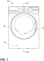
FIG. 1 is a front view of a laundry drying appliance according to some embodiments of the present disclosure; -
FIG. 2 is a cross-sectional view of the laundry drying appliance ofFIG. 1 taken along the line II-II; -
FIG. 3 is a front view of an appliance having a plurality of sanitation devices included according to some embodiments of the present disclosure; -
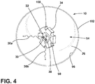
FIG. 4 is a front view of a sanitation device, according to some embodiments of the present disclosure; -
FIG. 5 is a rear view of a sanitation device, according to some embodiments of the present disclosure; -
FIG. 6 is a schematic flow diagram of a controller used in the sanitation device according to some embodiments of the present disclosure; -
FIG. 7 is a partial view of the appliance having the sanitation device removably attachable to a lifter coupled to an interior surface of the appliance according to some embodiments; -
FIG. 8 is a partial view of an interior surface of the appliance having a sensor assembly attached to a lifter within an interior of the appliance according to some embodiments; and -
FIG. 9 is a partial view of the appliance having a sensor assembly and a light source coupled to an interior surface of the appliance according to some embodiments. - For purposes of description herein, relational terms, such as first and second, top and bottom, and the like, are used solely to distinguish one entity or action from another entity or action, without necessarily requiring or implying any actual such relationship or order between such entities or actions. The terms "comprises," "comprising," or any other variation thereof, are intended to cover a non-exclusive inclusion, such that a process, method, article, or apparatus that comprises a list of elements does not include only those elements but may include other elements not expressly listed or inherent to such process, method, article, or apparatus. An element preceded by "comprises ... a" does not, without more constraints, preclude the existence of additional identical elements in the process, method, article, or apparatus that comprises the element.
- As required, detailed embodiments of the present disclosure are disclosed herein. However, it is to be understood that the disclosed embodiments are merely exemplary of the disclosure that may be embodied in various and alternative forms. The figures are not necessarily to a detailed design and some schematics may be exaggerated or minimized to show function overview. Therefore, specific structural and functional details disclosed herein are not to be interpreted as limiting, but merely as a representative basis for teaching one skilled in the art to variously employ the present disclosure.
- As used herein, the term "and/or," when used in a list of two or more items, means that any one of the listed items can be employed by itself, or any combination of two or more of the listed items can be employed. For example, if a composition is described as containing components A, B, and/or C, the composition can contain A alone; B alone; C alone; A and B in combination; A and C in combination; B and C in combination; or A, B, and C in combination.
- Ranges can be expressed herein as from "about" one particular value, and/or to "about" another particular value. As used herein, the term "about" means that amounts, sizes, formulations, parameters, and other quantities and characteristics are not and need not be exact., but may be approximate and/or larger or smaller, as desired, reflecting tolerances, conversion factors, rounding off, measurement error, and the like, and other factors known to those skilled in the art. When the term "about" is used in describing a value or an end-point of a range, the disclosure should be understood to include the specific value or end-point referred to. Whether or not a numerical value or end-point of a range in the specification recites "about," the numerical value or end-point of a range is intended to include two embodiments: one modified by "about" and one not modified by "about." It will be further understood that the endpoints of each of the ranges are significant both in relation to the other endpoint, and independently of the other endpoint.
- Referring to
FIGS. 1-9 ,reference numeral 10 generally refers to a sanitation device that may be used to sanitizelaundry 14 within anappliance 18. Thesanitation device 10 can include asensor assembly 22. Thesensor assembly 22 may be positioned within afirst housing 26 and can be configured to detect humidity, temperature, and/or color pigmentation. Thesanitation device 10 may include alight source 30 where thelight source 30 may emit ultraviolet (UV)light 30a. Thesanitation device 10 may include acontroller 34. Thecontroller 34 may be coupled to thesensor assembly 22 and configured to send and/or receive information from thesensor assembly 22. In some embodiments, theappliance 18 may be a laundry appliance. - As exemplified in
FIGS. 1 and2 , theappliance 18 forprocessing laundry 14 within adrum 38 of theappliance 18 is shown. In some embodiments, theappliance 18 may be alaundry drying appliance 18a. To assist in processing thelaundry 14 within thedrum 38, aheat pump system 42 can be configured tocondition process air 46 that is moved through anairflow path 50. Theheat pump system 42 may include one ormore heat exchangers 54, which may be in the form of an evaporator and a condenser. Theheat exchangers 54, in the form of evaporators, may be configured to dehumidifyprocess air 46 that is delivered from thedrum 38. Theprocess air 46 delivered from thedrum 38 can include moisture and lint particles that are carried away from the load oflaundry 14 and are moved by ablower 58 through theairflow path 50 to theheat exchangers 54. Theheat exchangers 54, in the form of condensers, of theheat pump system 42 can reject heat from a surface of the condenser and deliver this heat into theprocess air 46. Theprocess air 46 may thereby be heated and then delivered back to thedrum 38 for continuing the processing oflaundry 14. Theblower 58 of thelaundry drying appliance 18a can deliverprocess air 46 through theairflow path 50 that includes therotating drum 38 and thevarious heat exchangers 54 of theheat pump system 42. - Referring still to
FIGS. 1 and2 , during performance of a particular drying cycle, moisture can be removed from the load oflaundry 14 and moved to theheat exchangers 54 where the removed moisture can form condensation that may be captured within adrain channel 62 of thelaundry drying appliance 18a. Additionally, various otherresidual fluids 66, including moisture, water vapor, and condensation in thedrain channel 62, can be captured or otherwise deposited within portions of theairflow path 50 and can remain within theairflow path 50 after completion of the drying cycle. It should be appreciated that in alternative embodiments, a washing machine or a combination washing machine/dryer may be used without departing from the teachings herein. - Referring to
FIG. 3 , theappliance 18 is shown with the load oflaundry 14 therein. In some embodiments, theappliance 18 has abody 70 defining acavity 74. In other embodiments, theappliance 18 has thebody 70 enclosing thedrum 38 having a lifter 78 (FIG. 7 ) and/or a drum paddle coupled to aninterior surface 82 of thedrum 38. Thelifter 78 may be integrated within thedrum 38 or may be fixedly or removably attachable to theinterior surface 82 of thedrum 38. Theappliance 18 can have acontrol panel 86 configured to operate theappliance 18. It should be appreciated that theappliance 18 may be a washing machine, dryer, or other appliance that may utilize sanitation processes without departing from the teachings herein. - Referring still to
FIG. 3 , in some embodiments, it may be advantageous to use a plurality ofsanitation devices 10 in a single load oflaundry 14 to increase sanitation of regular and/or larger loads oflaundry 14. Thesanitation device 10 may be charged to have sufficient power to operate during a portion of or all of the appliance cleaning cycle (e.g. a wash or dry cycle). Once charged, thesanitation device 10 can be positioned inside theappliance 18 with thelaundry 14. Theappliance door 126 can be closed and a selected cycle started. The activation of theappliance 18 may act in combination with thecontroller 34 and/or thesensor assembly 22 to activate thesanitation device 10 through motion and/or information received by thesensor assembly 22. In some embodiments, thelight source 30 is capable of emitting UV-A (∼320-400 nanometers) and UV-C (∼100-290 nanometers) light to disrupt the outer membranes of microbes. - Still referring to
FIG. 3 , in some embodiments, thesanitation device 10 may be used in a washing machine. In other embodiments, thesanitation device 10 can be used in a dryer. In yet other embodiments, thesanitation device 10 may be used in both washing machines and dryers. - Referring to
FIGS. 3 and4 , included with the load oflaundry 14 may be thesanitation device 10, which may tumble with the load oflaundry 14 providing close proximity of thesanitation device 10 to thelaundry 14 to help facilitate sanitation of the fabrics. In some embodiments,sanitation device 10 may include thelight source 30, which may be configured to emit a combination of UV-A (∼320-400 nanometers), UV-B (∼280-320 nanometers), and/or UV-C (∼100-290 nanometers) light to sanitize the load oflaundry 14. In other embodiments, thelight source 30 may emit UV-A and/or UV-C light. In still other embodiments, thelight source 30 may emit UV-C light. When theappliance 18 is in use, there may be substrates in the air within thedrum 38 and/or combined with water, which may include, but is not limited to, water compounds, soil, chemicals, and detergent. In some embodiments, the UV-A light acts as an airborne disinfectant and the UV-C light acts as a disinfectant of fabrics, where the UV radiation can create a cascade of biological events, including of microbial deoxyribonucleic acid (DNA) damaging and rupturing outer membranes of the microbes. In various embodiments, thelight source 30 may be, for example, a III-nitride wide bandgap semiconductor UV light emitting diode (LED) source capable of emittingUV light 30a having a wavelength between about 330 nanometers to about 380 nanometers, where the selected range ofUV light 30a may increase sanitation oflaundry 14 through disinfecting fabrics from pathogens and/or bacteria. In some embodiments, sanitation is accomplished through LED light rays from thelight source 30. In other embodiments, thelight source 30 may emit UV-C light within a washing machine. In yet other embodiments, thelight source 30 may emit UV-A and UV-C light within a dryer. - Referring still to
FIGS. 3 and4 , thesanitation device 10 is shown according to some embodiments. Thesanitation device 10 can include thesensor assembly 22 positioned within thefirst housing 26. Thefirst housing 26 may be any shape including, for example, spherical, cylindrical, oblique, torrid, etc. In some embodiments, the spherical shape may be advantageous such that thesanitation device 10 can better minimize getting caught within the load oflaundry 14 during a washing or drying cycle so thesanitation device 10 is better circulated throughout thelaundry 14. Thefirst housing 26 may be made from a wide range of materials, including, but not limited to, plastic, acrylic, plexiglass, polypropylene, polycarbonate, or any other similar material. In some embodiments, thefirst housing 26 may be made of a transparent medium, about 0% transparent, about 25-100% transparent, about 40-100% transparent, about 50-100% transparent, about 60-95% transparent, about 70-90% transparent, about 80-95% transparent, or about 80-90% transparent so the UV and/orvisible light first housing 26 into theappliance 18. - Referring to
FIG. 4 , thesensor assembly 22 may be coupled to a printed circuit board (PCB) 90. In various embodiments, thesensor assembly 22, thePCB 90, and/or a combination thereof may be positioned within thefirst housing 26. In some embodiments, thesensor assembly 22 may be embedded within an interior 94 of thefirst housing 26. Thesensor assembly 22 may be configured to detect, for example, humidity, temperature, color pigmentation, and/or any combination thereof. It should be appreciated that thesensor assembly 22 may have one sensor or a number of sensors configured to detect humidity, temperature, and/or color pigmentation without departing from the teachings herein. In various embodiments, thesensor assembly 22 may be configured to detect humidity and/or temperature within thecavity 74 of theappliance 18. Sensing temperature and/or humidity within theappliance 18 may be advantageous to allow a user to know when the appliance cycle (e.g. a wash or dry cycle) is completed or if thelaundry 14 has not sufficiently dried. Such capabilities may also be advantageous to signal that thesanitation device 10 should continue sanitation of thelaundry 14 until a certain temperature and/or humidity is achieved. Detection of the color pigmentation of fabrics may be advantageous to help sanitize the fabrics without compromising the relative color of the fabrics. In some embodiments, thesensor assembly 22 may include infrared sensors such that thesensor assembly 22 may detect information from its surroundings through the transparentfirst housing 26. In other embodiments, thesensor assembly 22 may include apressure sensor 22a,humidity sensor 22b,temperature sensor 22c, and/orcolor sensor 22d (FIG. 6 ). In yet other embodiments, thesensor assembly 22 may include a sensor and/or sensors with a single wire digital interface integrated on a microchip. Thesensor assembly 22 may be operatively or electrically coupled to thecontroller 34 and can be configured to send and/or receive information from thecontroller 34. In some embodiments, thesensor assembly 22 is configured to detect color pigmentation of fabrics using thecolor sensor 22d. In other embodiments, thesensor assembly 22 is configured to detect temperature, humidity, and/or a combination thereof using thehumidity sensor 22b andtemperature sensor 22c, respectively, within the drum and is configured to send information to thecontroller 34. - Referring still to
FIG. 4 , thePCB 90 may be positioned on thecontroller 34, or otherwise positioned within thefirst housing 26, and includes a control having control circuitry with light source drive circuitry for controlling activation and deactivation of thelight source 30. In various embodiments, thePCB 90 may be coupled to afirst surface 108 of thecontroller 34. In other embodiments, thesensor assembly 22 and thelight source 30 may be coupled to thePCB 90 which is coupled to thefirst surface 108 of thecontroller 34. ThePCB 90 may be any type of circuit board including, but not limited to, a flexible PCB and/or rigid PCB. In alternate embodiments, the control may be positioned externally from thefirst housing 26 without departing from the scope of the present disclosure. In various embodiments, thePCB 90 may be enclosed within a support structure. - In some embodiments, the
controller 34 may be positioned within thefirst housing 26 of thesanitation device 10 and may be coupled to the power source 106 (FIG. 5 ). Thecontroller 34 may be a microchip and/or a cross-sectional disk embedded into thefirst housing 26. In other embodiments, the controller may be molded into thefirst housing 26. In yet other embodiments, thefirst housing 26 may be partially and/or substantially hollow and thecontroller 34 may be coupled to aninterior surface 96 of thefirst housing 26. In alternate embodiments, thecontroller 34 may be positioned on thebody 70 of the appliance 18 (FIG. 9 ). - Still referring to
FIG. 4 , thesanitation device 10 includes thelight source 30. Thelight source 30 may be positioned within thefirst housing 26 and coupled to thePCB 90. In various embodiments, thelight source 30 may be operatively or electrically coupled to thecontroller 34 and may be configured to send and/or receive information from thecontroller 34. In some embodiments, thelight source 30 is configured to emitUV light 30a or a comparable light thereof. TheUV light 30a may have a wavelength between about 300 nanometers to about 380 nanometers to help prevent fading of fabric color pigmentation. - With further reference to
FIG. 4 , in other embodiments, thelight source 30 may be configured to emitvisible light 30b or a comparable light thereof. Thelight source 30 may include, but is not limited to, fluorescent lighting, light emitting diodes (LEDs), organic LEDs (OLEDs), polymer LEDs (PLEDs), solid-state lighting, or any other form of lighting configured to emitvisible light 30b. The use of UV LEDs takes advantage of the relatively low cost of LEDs. In some embodiments, the light emitting device known in the art configured to emitvisible light 30b may be 4750K correlated color temperature (CCT) white LEDs. In some embodiments, the light source is configured to emitvisible light 30b andultraviolet light 30a, where theultraviolet light 30a has a wavelength between about 300nm to about 380nm to help prevent color alteration of fabrics. In other embodiments, wherein thelight source 30 is configured to emit both UV-A and UV-C light. - The
light source 30 may be operatively or electrically coupled to thepressure sensor 22a within the sensor assembly 22 (FIG. 6 ). In some embodiments, thepressure sensor 22a can be effected when thesanitation device 10 moves about thedrum 38 of theappliance 18. Thepressure sensor 22a may then act in combination with thesensor assembly 22 and/or thecontroller 34 to activate thelight source 30 during the appliance cycle (e.g. a wash or dry cycle). This can allow for sanitation of thelaundry 14 and/orappliance 18 when thelight source 30 emitsUV light 30a. This can also help a user see within theappliance 18 during a cycle when thelight source 30 emitsvisible light 30b. In some embodiments, thelight source 30 emitsvisible light 30b when theappliance 18 is in use. - Referring to
FIG. 5 , thesanitation device 10 may have apower source 106. Thepower source 106 may be coupled to thesensor assembly 22 and/or the controller 34 (FIG. 6 ). Thepower source 106 may be positioned within thefirst housing 26 or integrated into thefirst housing 26. In other embodiments, thepower source 106 may be integrated into thesecond housing 130. In some embodiments, thepower source 106 may be coupled to asecond surface 112 of thecontroller 34. In various embodiments, thesensor assembly 22 and the light source 30 (FIG. 4 ) may be coupled to thefirst surface 108 of thecontroller 34 and thepower source 106 may be coupled to thesecond surface 112 of thecontroller 34, wherein thefirst surface 108 and thesecond surface 112 are opposing surfaces. Thepower source 106 may include any direct current (DC) generating device, including, but not limited to, a lithium-ion battery. In some embodiments, thepower source 106 may be rechargeable. Thepower source 106 may be capable of withstanding temperatures up to about 65°C, 85°C, 100°C, 125°C, or 150°C. In various embodiments, thepower source 106 may be a rechargeable high temperature battery coupled to thelight source 30 and thePCB 90. In some embodiments, the rechargeable battery may be compact and light in weight (e.g, about 5-10 grams, about 10-20 grams, about 20-50 grams, about 50-100 grams, about 100-200 grams, or about 200-300 grams). Thepower source 106 will be capable of withstanding temperatures greater than the desired application or specific laundry appliances without departing from the teachings herein. In some embodiments, thepower source 106 can be a rechargeable battery capable of withstanding temperatures up to about 150°C. - With further reference to
FIG. 5 , in some embodiments, thepower source 106 may be configured to charge using the motion and/or induction provided by therespective appliance 18. In other embodiments, thepower source 106 may be charged by a charging member, such that placing thesanitation device 10 on the charging member will allow thesanitation device 10 to charge. In various embodiments, the charging member may be a remote cordless charging member that charges thepower source 106. In some embodiments, thesanitation device 10 may be powered to last a full cycle of theappliance 18, which may be between about 45 minutes to about 1.5 hours. In other embodiments, a full charge on thesanitation device 10 may last for several wash and/or dry cycles. In some embodiments, thepower source 106 is coupled to thesensor assembly 22, wherein thepower source 106 is configured to charge using motion, induction, and/or a combination thereof. In other embodiments, thepower source 106 is coupled to thefirst housing 26 and capable of withstanding temperatures up to about 150°C. - Still referring to
FIG. 5 , the sanitation device may include aheatsink 110. Theheatsink 110 may be positioned on anouter surface 102 of thefirst housing 26. In other embodiments theheatsink 110 may be integrally formed with thefirst housing 26 such that theheatsink 110 andfirst housing 26 form one continuous piece. In yet other embodiments, theheatsink 110 may be positioned the interior 94 of thefirst housing 26. In some embodiments, theheatsink 110 may be exposed between thesecond housing 130. In yet other embodiments, theheatsink 110 may be coupled to thesecond surface 112 of thecontroller 34. In various embodiments, theheatsink 110 may be coupled to the sensor assembly 22 (FIG. 6 ) and/or positioned proximate thesensor assembly 22. In some embodiments, theheatsink 110 may be configured to dissipate and/or transfer thermal energy proximate thesensor assembly 22 such that thesensor assembly 22 may detect temperature. In other embodiments, condensation may form on theheatsink 110 and theheatsink 110 may be positioned proximate thesensor assembly 22 such that thesensor assembly 22 may detect humidity. Theheatsink 110 may be made from, for example, reflective aluminum, aluminum alloy, or other reflective and/or conductive metal materials. In some embodiments, theheatsink 110 is coupled to thefirst housing 26 and coupled to thesensor assembly 22, wherein theheatsink 110 is configured to transfer thermal energy proximate the sensor assembly. In various embodiments, thesanitation device 10 does not include theheatsink 110. - Still referring to
FIG. 5 , in some embodiments, thefirst housing 26 may have alternating diameters. In various embodiments, thefirst housing 26 may be corrugated having ridges and grooves. In other embodiments, thefirst housing 26 may have a constant diameter (FIG. 4 ). - Referring to
FIG. 6 , thecontroller 34 can be configured to send and/or receive information from thesensor assembly 22. In various embodiments, thecontroller 34 may be electrically or operatively connected to thesensor assembly 22. Thesensor assembly 22 may include one or more sensors, including, but not limited to, thepressure sensor 22a, thehumidity sensor 22b, thetemperature sensor 22c, thecolor sensor 22d, and/or a combination thereof. Thecontroller 34 may also be electrically or operatively coupled thelight source 30, wherein thelight source 30 may emitUV light 30a and/orvisible light 30b (FIG. 4 ). Thecontroller 34 may be configured to send and/or receive information from thesensor assembly 22, thelight source 30, and/or a combination thereof. In some embodiments, thecontroller 34 of thesanitation device 10 may be configured to send information to a user device to update the user on the status of the appliance, cleaning cycle, sanitation process, and/or combination thereof. - Referring still to
FIG. 6 , in some embodiments, thecontroller 34 includes amemory 118 and aprocessor 114. Thememory 118 can contain a routine 122 for operation of thecontroller 34. Theprocessor 114 is coupled to thememory 118 and is configured to execute theroutines 122 contained in thememory 118. - In a specific example, the
sanitation device 10 may include thesensor assembly 22, having thehumidity sensor 22b, thetemperature sensor 22c, and thecolor sensor 22d. Thesanitation device 10 may also include alight source 30 configured to emitUV light 30a andvisible light 30b, wherein thesensor assembly 22 andlight source 30 may be embedded within thefirst housing 26 that is made of silicone. Thesanitation device 10 may include thepower source 106, wherein thepower source 106 may be a high temperature rechargeable battery configured to be charged through the cordless charging member. Information detected from thehumidity sensor 22b, thetemperature sensor 22c, and/or thecolor sensor 22d may be displayed through a human-machine interface (HMI) fascia indicator and/or relayed to a consumer mobile device. - Referring to
FIG. 7 , thesanitation device 10 may be removably attachable to thelifter 78 coupled to theinterior surface 82 of thedrum 38 of theappliance 18, which may be advantageous to help prevent thesanitation device 10 from being caught within thelaundry 14 while it is being washed and/or dried (FIG. 3 ). Anattachment feature 138 may be used to attach thesanitation device 10 to thelifter 78. Theattachment feature 138 may be, but is not limited to, a pin, adhesive, fastener, snap, buckle, or other feature for temporary and/or repeated attachment sufficient to secure thesanitation device 10 to thelifter 78 when theappliance 18 is in use. - With further reference to
FIG. 7 , thesanitation device 10 may include asecond housing 130 coupled to the outer surface 102 (FIG. 4 ) of thefirst housing 26. Thesecond housing 130 may cover all or a portion of thefirst housing 26. In other embodiments, thesecond housing 130 may be made of silicone, UV transparent silicone, rubber, polyurethane, polyisoprene, nitrile, or other elastomeric known in the art materials. Thesecond housing 130 may act as bumper providing physical protection for thesanitation device 10 as it tumbles about thedrum 38 of the appliance 18 (FIG. 3 ). In some embodiments, thesecond housing 130 may be a variety of different colors. In other embodiments, thesecond housing 130 is coupled to an outer surface 102 (FIG. 5 ) of thefirst housing 26, wherein thesecond housing 130 covers a portion of thefirst housing 26 and the first andsecond housings second housing 130 can be a spiral band, concentric rings, and/or one or more bands where thefirst housing 26 is exposed to the cleaning environment. - Referring to
FIG. 8 , asanitation system 134 may include theappliance 18 enclosing thedrum 38, where thedrum 38 has thelifter 78 coupled to theinterior surface 82 of thedrum 38. Thesensor assembly 22 may be removably coupled to thelifter 78. In other embodiments, thelight source 30 may be coupled to thesensor assembly 22. In some embodiments thelight source 30 may be positioned on thelifter 78 proximate thesensor assembly 22. In yet other embodiments, thelight source 30 and/or thesensor assembly 22 may be coupled to thePCB 90. In some embodiments, thePCB 90 may be coupled to thelifter 78. In various embodiments, thePCB 90 may be coupled to thecontroller 34. - Referring still to
FIG. 8 , in some embodiments, thecontroller 34 may be positioned on thelifter 78 proximate thesensor assembly 22 and/or thelight source 30. Thecontroller 34 may be positioned within thefirst housing 26. In various embodiments, thecontroller 34 may be coupled tosensor assembly 22 and/or thelight source 30 and configured to send and/or receive information from thesensor assembly 22 and/or thelight source 30. - Referring to
FIG. 9 , theappliance 18 is shown having thebody 70 defining thecavity 74. Thesensor assembly 22 may be coupled to aninterior surface 152 of thecavity 74. Thesensor assembly 22 may be configured to detect humidity, temperature, and/or a combination thereof within thecavity 74. Thesensor assembly 22 may be operatively or electrically to thecontroller 34. - Still referring
FIG. 9 , thelight source 30 can be coupled to thesensor assembly 22, wherein thelight source 30 may be configured to emitUV light 30a, which may have a wavelength between about 300 nanometer to about 380 nanometer to help prevent color alteration of fabrics. In other embodiments, thelight source 30 may emitvisible light 30b or comparable light thereof, which may be configured to illuminate while theappliance 18 is in use. In yet other embodiments, thelight source 30 may emitUV light 30a andvisible light 30b. Thelight source 30 may include, but is not limited to, fluorescent lighting, light emitting diodes (LEDs), organic LEDs (OLEDs), polymer LEDs (PLEDs), solid-state lighting, or any other form of lighting configured to emit light. Thelight source 30 may be operatively or electrically coupled to thecontroller 34. Thelight source 30 can be coupled to thePCB 90, which contains a control having control circuitry with light source drive circuitry for controlling activation and deactivation of thelight source 30. ThePCB 90 may be any type of circuit board including, but not limited to, a flexible PCB and/or rigid PCB. - Referring still to
FIG. 9 , thecontroller 34 may be configured to send and/or receive information from thesensor assembly 22 and/or thelight source 30. In some embodiments, thecontroller 34 may be positioned proximate to thesensor assembly 22 and/or thelight source 30. In other embodiments, thecontroller 34 may be positioned in any location on thebody 70 of theappliance 18, including, but not limited to, proximate to or positioned on thecontrol panel 86. - With further reference to
FIG. 9 , in some embodiments, thesensor assembly 22 and/or thelight source 30 may be fixedly mounted to theinterior surface 152 of thecavity 74 of theappliance 18. Thesensor assembly 22, thelight source 30, and/or thecontroller 34 may be powered by theappliance 18, which may be advantageous to keep thesensor assembly 22 and/or thelight source 30 in close proximity to thelaundry 14 within theappliance 18 while preventing thesensor assembly 22 and/orlight source 30 from getting caught within thelaundry 14. In some embodiments, thesensor assembly 22 may be positioned within thefirst housing 26 and/or the second housing 130 (FIG. 8 ). In some embodiments, thefirst housing 26 is positioned about thesensor assembly 22 and coupled to theinterior surface 152 of thecavity 74. - In a specific example, the
PCB 90 may be a flatpack coupled to thelight source 30 and thesensor assembly 22. Thelight source 30 may be configured to emitUV light 30a andvisible light 30b. The sensor assembly may include thehumidity sensor 22b,temperature sensor 22c, andcolor sensor 22d. ThePCB 90,light source 30, andsensor assembly 22 may be coupled to theinterior surface 152 of thecavity 74 of theappliance 18 and not embedded and/or positioned within thefirst housing 26. In another example, thePCB 90,light source 30, andsensor assembly 22 may be coupled to the lifter 78 (FIG. 8 ). - In yet other embodiments, the
sensor assembly 22 may include a sensor and/or sensors with a single wire digital interface integrated on a microchip. The microchip may also include thelight source 30 and be coupled to thePCB 90. The microchip may be directly mounted to theinterior surface 152 of thecavity 74 of theappliance 18. - According to at least one aspect of the present disclosure, a sanitation device for an appliance includes a first housing and a sensor assembly positioned within the first housing. The sensor assembly includes a humidity sensor and a temperature sensor, and is configured to detect humidity and temperature in the appliance. A light source is coupled to the sensor assembly. The light source emits ultraviolet light. A controller is coupled to the sensor assembly and is configured to send and receive information from the sensor assembly.
- According to another aspect, a power source is coupled to a sensor assembly. The power source is configured to charge using at least one of motion and induction.
- According to still another aspect, a power source is a rechargeable battery configured to withstand temperatures up to about 150°C.
- According to another aspect, a heatsink is coupled to a controller. The controller is positioned within at least one housing.
- According to yet another aspect, a light source is configured to emit visible light and ultraviolet light. The ultraviolet light has a wavelength in a range of from about 300nm to about 380nm to reduce color alteration of fabrics.
- According to another aspect, a sensor assembly includes a color sensor and is configured to detect color pigmentation of fabrics.
- According to yet another aspect, a light source is configured to emit both UV-A and UV-C light.
- According to another aspect, at least one housing includes a first housing and a second housing. The second housing is coupled to an outer surface of the first housing. The second housing covers a portion of the outer surface of the first housing. The first and second housings are spherical.
- According to still another aspect, a sensor assembly includes a pressure sensor.
- According to another aspect, a laundry appliance includes a sanitation device.
- According to at least one aspect of the present disclosure, a sanitation system includes a laundry appliance that has a body that encloses a drum and a lifter coupled to an interior surface of the drum. A sensor assembly is removably coupled to the lifter. A light source is positioned proximate the sensor assembly. A controller is positioned on the lifter and coupled to the sensor assembly. The controller is configured to send and receive information from the sensor assembly.
- According to another aspect, a power source is coupled to the sensor assembly and configured to withstand temperatures up to about 150°C.
- According to still another aspect, a light source emits ultraviolet light and visible light.
- According to another aspect, a sensor assembly is configured to detect at least one of temperature, humidity, and/or a combination thereof within a drum, and is configured to send information to the controller.
- According to yet another aspect, a light source is configured to emit both UV-A and UV-C light.
- According to another aspect, a light source emits visible light when a laundry appliance is in use.
- According to at least one aspect of the present disclosure, an appliance includes a body that defines a cavity. A sensor assembly is coupled to an interior surface of the cavity. The sensor assembly is configured to detect at least one of humidity and temperature within the cavity. A light source is coupled to the sensor assembly. The light source emits ultraviolet light. A controller is operatively coupled to the sensor assembly and configured to send and receive information from the sensor assembly.
- According to another aspect, a light source emits visible light and is configured to illuminate an interior of a cavity while an appliance is in use.
- According to still another aspect, an ultraviolet light has a wavelength in a range of from about 300nm to about 380nm to reduce color alteration of fabrics positioned within a cavity.
- According to another aspect, a first housing is positioned about a sensor assembly and is coupled to an interior surface of a cavity.
- According to another aspect, a light source is configured to emit both UV-A and UV-C light.
- According to yet another aspect, a controller is positioned on a body of an appliance.
- It will be understood by one having ordinary skill in the art that construction of the described disclosure, and other components, is not limited to any specific material. Other exemplary embodiments of the disclosure disclosed herein may be formed from a wide variety of materials, unless described otherwise herein.
- For purposes of this disclosure, the term "coupled" (in all of its forms: couple, coupling, coupled, etc.) generally means the joining of two components (electrical or mechanical) directly or indirectly to one another. Such joining may be stationary in nature or movable in nature. Such joining may be achieved with the two components (electrical or mechanical) and any additional intermediate members being integrally formed as a single unitary body with one another or with the two components. Such joining may be permanent in nature, or may be removable or releasable in nature, unless otherwise stated.
- It is also important to note that the construction and arrangement of the elements of the disclosure, as shown in the exemplary embodiments, is illustrative only. Although only a few embodiments of the present innovations have been described in detail in this disclosure, those skilled in the art who review this disclosure will readily appreciate that many modifications are possible (e.g., variations in sizes, dimensions, structures, shapes and proportions of the various elements, values of parameters, mounting arrangements, use of materials, colors, orientations, etc.) without materially departing from the novel teachings and advantages of the subject matter recited. For example, elements shown as integrally formed may be constructed of multiple parts, or elements shown as multiple parts may be integrally formed, the operation of the interfaces may be reversed or otherwise varied, the length or width of the structures and/or members or connector or other elements of the system may be varied, and the nature or numeral of adjustment positions provided between the elements may be varied. It should be noted that the elements and/or assemblies of the system may be constructed from any of a wide variety of materials that provide sufficient strength or durability, in any of a wide variety of colors, textures, and combinations. Accordingly, all such modifications are intended to be included within the scope of the present innovations. Other substitutions, modifications, changes, and omissions may be made in the design, operating conditions, and arrangement of the desired and other exemplary embodiments without departing from the spirit of the present innovations.
- It will be understood that any described processes, or steps within described processes, may be combined with other disclosed processes or steps to form structures within the scope of the present disclosure. The exemplary structures and processes disclosed herein are for illustrative purposes and are not to be construed as limiting.
- It is to be understood that variations and modifications can be made on the aforementioned structure without departing from the concepts of the present disclosure, and further it is to be understood that such concepts are intended to be covered by the following claims unless these claims by their language expressly state otherwise.
Claims (15)
- A sanitation device (10) for an appliance (18), comprising:at least one housing (26);a sensor assembly (22) positioned within the at least one housing (26), wherein the sensor assembly (22) includes a humidity sensor (22b) and a temperature sensor (22c);a light source (30) coupled to the sensor assembly (22), wherein the light source (30) emits ultraviolet light (30a); anda controller (34) operatively coupled to the sensor assembly (22) and configured to send and receive information from the sensor assembly (22).
- The sanitation device (10) of claim 1, further comprising:
a power source (106) coupled to the sensor assembly (22), wherein the power source (106) is configured to charge using at least one of motion and induction. - The sanitation device (10) of claim 2, wherein the power source (106) is a rechargeable battery configured to withstand temperatures up to about 150°C.
- The sanitation device (10) of any one of claims 1-3, wherein the sensor assembly (22) includes a color sensor (22d) configured to detect color pigmentation of fabrics.
- The sanitation device (10) of any one of claims 1-4, wherein the at least one housing (26) is spherical.
- The sanitation device (10) of any one of claims 1-5, wherein the at least one housing (26) includes a first housing (26) and a second housing (130) coupled to an outer surface (102) of the first housing (26).
- The sanitation device (10) of claim 6, wherein the second housing (130) covers a portion of the outer surface (102) of the first housing (26).
- The sanitation device (10) of any one of claims 1-7, further comprising:
a heatsink (110) coupled to the controller (34), wherein the controller (110) is positioned within the at least one housing (26). - The sanitation device (10) of any one of claims 1-8, wherein the ultraviolet light (30a) is UV-A light.
- The sanitation device (10) of any one of claims 1-9, wherein the ultraviolet light (30a) is UV-C light.
- The sanitation device (10) of any one of claims 1-10, wherein the sensor assembly (22) includes a pressure sensor (22a).
- The sanitation device (10) of any one of claims 1-11, wherein the light source (30) is configured to emit visible light (30b).
- The sanitation device (10) of claim 12, wherein the light source (30) emits the visible light (30b) and is configured to illuminate an interior of said appliance (18).
- The sanitation device (10) of any one of claims 1-13, wherein the ultraviolet light (30a) has a wavelength in a range of from about 300 nm to about 380 nm.
- A laundry appliance (18a) that includes the sanitation device (10) of any one of claims 1-14.
Applications Claiming Priority (1)
| Application Number | Priority Date | Filing Date | Title |
|---|---|---|---|
| US16/144,453 US11085147B2 (en) | 2018-09-27 | 2018-09-27 | Sanitation device |
Publications (1)
| Publication Number | Publication Date |
|---|---|
| EP3628769A1 true EP3628769A1 (en) | 2020-04-01 |
Family
ID=68072195
Family Applications (1)
| Application Number | Title | Priority Date | Filing Date |
|---|---|---|---|
| EP19199981.2A Withdrawn EP3628769A1 (en) | 2018-09-27 | 2019-09-26 | Sanitation device |
Country Status (3)
| Country | Link |
|---|---|
| US (3) | US11085147B2 (en) |
| EP (1) | EP3628769A1 (en) |
| CN (1) | CN110960709B (en) |
Cited By (3)
| Publication number | Priority date | Publication date | Assignee | Title |
|---|---|---|---|---|
| WO2022008447A1 (en) * | 2020-07-09 | 2022-01-13 | Marco Begerok | Washing machine or dishwasher for cleaning laundry or dishes |
| WO2023139437A1 (en) * | 2022-01-19 | 2023-07-27 | Marco Borgiani | Device for water sanification |
| US12624488B2 (en) | 2020-12-08 | 2026-05-12 | Samsung Electronics Co., Ltd. | Electronic apparatus and sensor ball registration method of electronic apparatus |
Families Citing this family (3)
| Publication number | Priority date | Publication date | Assignee | Title |
|---|---|---|---|---|
| CN111120977B (en) * | 2018-10-29 | 2022-06-14 | 通用电气照明解决方案有限公司 | Lighting sterilization system |
| WO2021232189A1 (en) * | 2020-05-18 | 2021-11-25 | Haier Us Appliance Solutions, Inc. | Low-friction drying system |
| US12601103B2 (en) * | 2021-11-17 | 2026-04-14 | Whirlpool Corporation | Foreign substrate collector for a laundry appliance |
Citations (3)
| Publication number | Priority date | Publication date | Assignee | Title |
|---|---|---|---|---|
| EP1960585A1 (en) * | 2005-11-18 | 2008-08-27 | LG Electronics Inc. | Sterilizable drying machine using ultraviolet radiation and sterilizable drying method in the same |
| KR101862515B1 (en) * | 2017-05-24 | 2018-05-31 | 박윤석 | Washing ball with sterilization functoin |
| WO2018114358A1 (en) * | 2016-12-21 | 2018-06-28 | Henkel Ag & Co. Kgaa | Metering device for a cleaning machine |
Family Cites Families (36)
| Publication number | Priority date | Publication date | Assignee | Title |
|---|---|---|---|---|
| IT1078261B (en) | 1977-05-16 | 1985-05-08 | Renzacci Spa | IMPROVEMENT IN WASHING AND DRYING MACHINES FOR CLOTHING AND LINEN |
| US5664340A (en) | 1996-03-18 | 1997-09-09 | Brown; Clay A. | Ultravoilet, antibacterial, antifungal dryerlight |
| US6958693B2 (en) * | 2002-05-24 | 2005-10-25 | Procter & Gamble Company | Sensor device and methods for using same |
| JP3739377B2 (en) | 2003-12-10 | 2006-01-25 | シャープ株式会社 | Washing and drying machine |
| KR20060036664A (en) * | 2004-10-26 | 2006-05-02 | 엘지전자 주식회사 | Heat sink structure of washing machine controller |
| US20060260366A1 (en) | 2005-05-18 | 2006-11-23 | I+Dcreative, Llc | Laundry appliance for washing small quantities of clothing |
| CN101198233A (en) | 2006-12-08 | 2008-06-11 | 奥斯兰姆奥普托半导体有限责任公司 | Electric appliance |
| KR101394514B1 (en) * | 2007-03-29 | 2014-05-14 | 엘지전자 주식회사 | Operating method for washing machine |
| DE102009008031A1 (en) | 2008-11-06 | 2010-06-02 | Peter Trossowski | Device for disinfecting textiles, in particular UV disinfecting washing balls, their use and methods for disinfecting textiles |
| TWM378242U (en) * | 2009-08-31 | 2010-04-11 | Ching-Chen Hung | A wash ball with violet light lightened |
| CN102021782B (en) * | 2009-09-09 | 2012-05-23 | 建兴电子科技股份有限公司 | Laundry ball device with disinfection and sterilization function |
| US10443938B2 (en) * | 2009-11-08 | 2019-10-15 | Ga Innovation, Llc | Retrofit moisture and humidity sensor and automatic shutoff device for clothes dryers |
| CN201722525U (en) | 2010-05-26 | 2011-01-26 | 方益民 | Ultraviolet disinfection washing machine |
| US8881422B2 (en) * | 2010-08-25 | 2014-11-11 | Uvdry, Llc | Apparatus for drying laundry or other items using ultra-violet radiation |
| KR101222784B1 (en) * | 2012-09-03 | 2013-01-15 | 주식회사 이온팜스 | Washing ball |
| US9044867B2 (en) * | 2012-12-04 | 2015-06-02 | Michael Benn Rothschild | Autonomous rechargeable heated child's mat |
| DE102012112199B4 (en) * | 2012-12-13 | 2016-01-14 | Miele & Cie. Kg | Laundry treatment machine, in particular tumble dryer |
| WO2014104796A1 (en) * | 2012-12-28 | 2014-07-03 | Seoul Viosys Co., Ltd. | Washing machine having ultraviolet light-emitting diode |
| US20140351832A1 (en) * | 2013-05-21 | 2014-11-27 | Samsung Electronics Co., Ltd. | Electronic device using framework interface for communication |
| US20150211165A1 (en) | 2014-01-24 | 2015-07-30 | The Procter & Gamble Company | Method for Treating Laundry |
| WO2015116833A1 (en) | 2014-01-29 | 2015-08-06 | P Tech, Llc | Systems and methods for disinfection |
| US9833526B2 (en) | 2014-02-25 | 2017-12-05 | Sensor Electronic Technology, Inc. | Ultraviolet illuminator |
| US9687577B2 (en) * | 2014-09-13 | 2017-06-27 | Sensor Electronic Technology, Inc. | Ultraviolet illuminator for footwear treatment |
| PL3002356T3 (en) * | 2014-10-03 | 2017-09-29 | Electrolux Appliances Aktiebolag | Laundry washing machine and control method thereof |
| US10024597B2 (en) | 2014-11-26 | 2018-07-17 | Extractor Corporation | Centrifugal separator |
| WO2016182540A1 (en) * | 2015-05-08 | 2016-11-17 | Dexter Laundry, Inc. | Wireless communication assembly |
| US11098429B2 (en) * | 2015-09-17 | 2021-08-24 | Washlava, Inc. | Communication and control system for laundry machines |
| US9903673B1 (en) | 2015-09-27 | 2018-02-27 | Sentinel Diagnostics, LLC | Intelligent ball for monitoring and diagnosis of heat exchanger tube health |
| CN205917482U (en) | 2016-07-08 | 2017-02-01 | 中山东菱威力电器有限公司 | A washing machine with ultraviolet sterilizing function |
| CN106012406B (en) | 2016-07-08 | 2019-01-18 | 中山东菱威力电器有限公司 | A kind of washing machine having ultraviolet radiation for sterilizing and disinfecting function |
| DE102016212984A1 (en) * | 2016-07-15 | 2018-01-18 | Henkel Ag & Co. Kgaa | Check for potentially unwanted items of laundry |
| KR101904236B1 (en) * | 2016-12-09 | 2018-10-04 | (주)인투케어 | Portable sterilization ball |
| DE102016225113A1 (en) * | 2016-12-15 | 2018-06-21 | BSH Hausgeräte GmbH | Method for operating a laundry treatment appliance with improved control and suitable laundry treatment appliance |
| KR101747408B1 (en) * | 2017-03-28 | 2017-06-14 | 이수완 | Portavle ultraviolet sterilizer uv ball and ultraviolet sterilization method using the same |
| CN107044032A (en) * | 2017-06-14 | 2017-08-15 | 江苏钜芯集成电路技术股份有限公司 | Ultraviolet sterilization ball for washing machine |
| KR101936638B1 (en) * | 2017-06-21 | 2019-01-09 | 엘지전자 주식회사 | Washing machine |
-
2018
- 2018-09-27 US US16/144,453 patent/US11085147B2/en active Active
-
2019
- 2019-09-26 CN CN201910916116.2A patent/CN110960709B/en not_active Expired - Fee Related
- 2019-09-26 EP EP19199981.2A patent/EP3628769A1/en not_active Withdrawn
-
2021
- 2021-07-22 US US17/382,682 patent/US11725336B2/en active Active
-
2023
- 2023-06-29 US US18/216,251 patent/US12540433B2/en active Active
Patent Citations (3)
| Publication number | Priority date | Publication date | Assignee | Title |
|---|---|---|---|---|
| EP1960585A1 (en) * | 2005-11-18 | 2008-08-27 | LG Electronics Inc. | Sterilizable drying machine using ultraviolet radiation and sterilizable drying method in the same |
| WO2018114358A1 (en) * | 2016-12-21 | 2018-06-28 | Henkel Ag & Co. Kgaa | Metering device for a cleaning machine |
| KR101862515B1 (en) * | 2017-05-24 | 2018-05-31 | 박윤석 | Washing ball with sterilization functoin |
Cited By (4)
| Publication number | Priority date | Publication date | Assignee | Title |
|---|---|---|---|---|
| WO2022008447A1 (en) * | 2020-07-09 | 2022-01-13 | Marco Begerok | Washing machine or dishwasher for cleaning laundry or dishes |
| US20240026591A1 (en) * | 2020-07-09 | 2024-01-25 | Marco Begerok | Washing Machine or Dishwasher for Cleaning Laundry or Dishes |
| US12624488B2 (en) | 2020-12-08 | 2026-05-12 | Samsung Electronics Co., Ltd. | Electronic apparatus and sensor ball registration method of electronic apparatus |
| WO2023139437A1 (en) * | 2022-01-19 | 2023-07-27 | Marco Borgiani | Device for water sanification |
Also Published As
| Publication number | Publication date |
|---|---|
| CN110960709A (en) | 2020-04-07 |
| US11725336B2 (en) | 2023-08-15 |
| US11085147B2 (en) | 2021-08-10 |
| US20200102695A1 (en) | 2020-04-02 |
| CN110960709B (en) | 2022-11-18 |
| US20230349092A1 (en) | 2023-11-02 |
| US20210355627A1 (en) | 2021-11-18 |
| US12540433B2 (en) | 2026-02-03 |
Similar Documents
| Publication | Publication Date | Title |
|---|---|---|
| US12540433B2 (en) | Sanitation device | |
| US6877248B1 (en) | Clothes dryer with ultraviolet light | |
| KR101243727B1 (en) | Drying wardrobe | |
| US20200384140A1 (en) | Uv disinfection apparatus, method therefor, and use thereof | |
| US10145055B1 (en) | Apparatus and methods for ultraviolet light treatment of laundry | |
| WO2018119237A1 (en) | Shopping cart with sterilization mechanism | |
| KR100971006B1 (en) | Shoe sterilization dryer | |
| US20180363211A1 (en) | Wall-mounted washing machine | |
| KR20190014780A (en) | (deodorization, disinfection and drying cabinet for shoes and multipurpose | |
| KR20220037356A (en) | Lighting apparatus for a container device of a household appliance | |
| KR101013495B1 (en) | Rubber gloves dryer | |
| WO2017048435A1 (en) | Self-contained, portatable drying appliance for dishwashers | |
| WO2006083073A1 (en) | Far infrared sterilizer for shoes and shoes rack having the same mounted therein | |
| CN101313100B (en) | Sterilizable washing machine using ultraviolet radiation and sterilizable washing method in the same | |
| CN212670085U (en) | An underwear drying box | |
| CN211897460U (en) | Multi-drum washing machine | |
| CN213046693U (en) | Multifunctional bathroom rack | |
| CN211408123U (en) | Equipment cabinet | |
| EP2687143A3 (en) | Washing and/or drying machine for domestic use | |
| CN102302277A (en) | Intelligent environment-friendly shoe cabinet with sterilization and deodorization functions | |
| CN100419150C (en) | Conjoined multifunctional device for realizing drying, sterilization and flatiron | |
| CN215350942U (en) | hand towel sanitizer | |
| CN204766679U (en) | Handheld Sterilizer | |
| WO2026099643A1 (en) | Integrated sanitizing system for a household appliance | |
| KR200404136Y1 (en) | military shoes drier |
Legal Events
| Date | Code | Title | Description |
|---|---|---|---|
| PUAI | Public reference made under article 153(3) epc to a published international application that has entered the european phase |
Free format text: ORIGINAL CODE: 0009012 |
|
| STAA | Information on the status of an ep patent application or granted ep patent |
Free format text: STATUS: THE APPLICATION HAS BEEN PUBLISHED |
|
| AK | Designated contracting states |
Kind code of ref document: A1 Designated state(s): AL AT BE BG CH CY CZ DE DK EE ES FI FR GB GR HR HU IE IS IT LI LT LU LV MC MK MT NL NO PL PT RO RS SE SI SK SM TR |
|
| AX | Request for extension of the european patent |
Extension state: BA ME |
|
| STAA | Information on the status of an ep patent application or granted ep patent |
Free format text: STATUS: REQUEST FOR EXAMINATION WAS MADE |
|
| 17P | Request for examination filed |
Effective date: 20200930 |
|
| RBV | Designated contracting states (corrected) |
Designated state(s): AL AT BE BG CH CY CZ DE DK EE ES FI FR GB GR HR HU IE IS IT LI LT LU LV MC MK MT NL NO PL PT RO RS SE SI SK SM TR |
|
| STAA | Information on the status of an ep patent application or granted ep patent |
Free format text: STATUS: EXAMINATION IS IN PROGRESS |
|
| 17Q | First examination report despatched |
Effective date: 20240313 |
|
| STAA | Information on the status of an ep patent application or granted ep patent |
Free format text: STATUS: THE APPLICATION HAS BEEN WITHDRAWN |
|
| 18W | Application withdrawn |
Effective date: 20240603 |