EP3628648A1 - Cement - Google Patents
Cement Download PDFInfo
- Publication number
- EP3628648A1 EP3628648A1 EP19196018.6A EP19196018A EP3628648A1 EP 3628648 A1 EP3628648 A1 EP 3628648A1 EP 19196018 A EP19196018 A EP 19196018A EP 3628648 A1 EP3628648 A1 EP 3628648A1
- Authority
- EP
- European Patent Office
- Prior art keywords
- cement
- composition according
- component
- oxide
- metal oxides
- Prior art date
- Legal status (The legal status is an assumption and is not a legal conclusion. Google has not performed a legal analysis and makes no representation as to the accuracy of the status listed.)
- Withdrawn
Links
- 239000004568 cement Substances 0.000 title claims description 41
- VYPSYNLAJGMNEJ-UHFFFAOYSA-N Silicium dioxide Chemical compound O=[Si]=O VYPSYNLAJGMNEJ-UHFFFAOYSA-N 0.000 claims abstract description 51
- 239000000203 mixture Substances 0.000 claims abstract description 31
- GWEVSGVZZGPLCZ-UHFFFAOYSA-N Titan oxide Chemical compound O=[Ti]=O GWEVSGVZZGPLCZ-UHFFFAOYSA-N 0.000 claims abstract description 21
- PNEYBMLMFCGWSK-UHFFFAOYSA-N aluminium oxide Inorganic materials [O-2].[O-2].[O-2].[Al+3].[Al+3] PNEYBMLMFCGWSK-UHFFFAOYSA-N 0.000 claims abstract description 20
- 239000000377 silicon dioxide Substances 0.000 claims abstract description 20
- 229910044991 metal oxide Inorganic materials 0.000 claims abstract description 19
- 150000004706 metal oxides Chemical class 0.000 claims abstract description 19
- QVQLCTNNEUAWMS-UHFFFAOYSA-N barium oxide Chemical compound [Ba]=O QVQLCTNNEUAWMS-UHFFFAOYSA-N 0.000 claims abstract description 18
- 229910052751 metal Inorganic materials 0.000 claims abstract description 15
- 239000002184 metal Substances 0.000 claims abstract description 15
- 239000000243 solution Substances 0.000 claims abstract description 12
- 150000003839 salts Chemical class 0.000 claims abstract description 11
- WGLPBDUCMAPZCE-UHFFFAOYSA-N Trioxochromium Chemical compound O=[Cr](=O)=O WGLPBDUCMAPZCE-UHFFFAOYSA-N 0.000 claims abstract description 9
- 229910000423 chromium oxide Inorganic materials 0.000 claims abstract description 9
- 229910000147 aluminium phosphate Inorganic materials 0.000 claims abstract description 7
- 239000003929 acidic solution Substances 0.000 claims abstract description 6
- 239000008119 colloidal silica Substances 0.000 claims abstract description 6
- ILRRQNADMUWWFW-UHFFFAOYSA-K aluminium phosphate Chemical compound O1[Al]2OP1(=O)O2 ILRRQNADMUWWFW-UHFFFAOYSA-K 0.000 claims abstract description 5
- 229940001007 aluminium phosphate Drugs 0.000 claims abstract description 5
- BPQQTUXANYXVAA-UHFFFAOYSA-N Orthosilicate Chemical compound [O-][Si]([O-])([O-])[O-] BPQQTUXANYXVAA-UHFFFAOYSA-N 0.000 claims abstract description 4
- OGIDPMRJRNCKJF-UHFFFAOYSA-N titanium oxide Inorganic materials [Ti]=O OGIDPMRJRNCKJF-UHFFFAOYSA-N 0.000 claims abstract description 3
- 230000002378 acidificating effect Effects 0.000 claims abstract 2
- 238000000034 method Methods 0.000 claims description 17
- 238000002156 mixing Methods 0.000 claims description 13
- 229910000314 transition metal oxide Inorganic materials 0.000 claims description 12
- 229910000287 alkaline earth metal oxide Inorganic materials 0.000 claims description 10
- ZLMJMSJWJFRBEC-UHFFFAOYSA-N Potassium Chemical compound [K] ZLMJMSJWJFRBEC-UHFFFAOYSA-N 0.000 claims description 2
- 239000004111 Potassium silicate Substances 0.000 claims description 2
- 239000004115 Sodium Silicate Substances 0.000 claims description 2
- 239000002245 particle Substances 0.000 claims description 2
- 229910052913 potassium silicate Inorganic materials 0.000 claims description 2
- 235000019353 potassium silicate Nutrition 0.000 claims description 2
- NTHWMYGWWRZVTN-UHFFFAOYSA-N sodium silicate Chemical compound [Na+].[Na+].[O-][Si]([O-])=O NTHWMYGWWRZVTN-UHFFFAOYSA-N 0.000 claims description 2
- 229910052911 sodium silicate Inorganic materials 0.000 claims description 2
- 159000000013 aluminium salts Chemical group 0.000 claims 1
- 229910000329 aluminium sulfate Inorganic materials 0.000 claims 1
- 239000004408 titanium dioxide Substances 0.000 description 9
- 239000000463 material Substances 0.000 description 7
- 238000011144 upstream manufacturing Methods 0.000 description 6
- RTAQQCXQSZGOHL-UHFFFAOYSA-N Titanium Chemical compound [Ti] RTAQQCXQSZGOHL-UHFFFAOYSA-N 0.000 description 5
- 235000013312 flour Nutrition 0.000 description 5
- 239000010936 titanium Substances 0.000 description 5
- 229910052719 titanium Inorganic materials 0.000 description 5
- NBIIXXVUZAFLBC-UHFFFAOYSA-N Phosphoric acid Chemical compound OP(O)(O)=O NBIIXXVUZAFLBC-UHFFFAOYSA-N 0.000 description 4
- 230000001141 propulsive effect Effects 0.000 description 4
- 239000004576 sand Substances 0.000 description 4
- 239000004411 aluminium Substances 0.000 description 3
- 229910052782 aluminium Inorganic materials 0.000 description 3
- XAGFODPZIPBFFR-UHFFFAOYSA-N aluminium Chemical compound [Al] XAGFODPZIPBFFR-UHFFFAOYSA-N 0.000 description 3
- JOSWYUNQBRPBDN-UHFFFAOYSA-P ammonium dichromate Chemical compound [NH4+].[NH4+].[O-][Cr](=O)(=O)O[Cr]([O-])(=O)=O JOSWYUNQBRPBDN-UHFFFAOYSA-P 0.000 description 3
- 238000002485 combustion reaction Methods 0.000 description 3
- XLYOFNOQVPJJNP-UHFFFAOYSA-N water Substances O XLYOFNOQVPJJNP-UHFFFAOYSA-N 0.000 description 3
- 229910001148 Al-Li alloy Inorganic materials 0.000 description 2
- FCVHBUFELUXTLR-UHFFFAOYSA-N [Li].[AlH3] Chemical compound [Li].[AlH3] FCVHBUFELUXTLR-UHFFFAOYSA-N 0.000 description 2
- 239000002253 acid Substances 0.000 description 2
- 239000000654 additive Substances 0.000 description 2
- 230000000996 additive effect Effects 0.000 description 2
- 238000000498 ball milling Methods 0.000 description 2
- 230000009286 beneficial effect Effects 0.000 description 2
- 230000000711 cancerogenic effect Effects 0.000 description 2
- 231100000315 carcinogenic Toxicity 0.000 description 2
- AYTAKQFHWFYBMA-UHFFFAOYSA-N chromium dioxide Chemical compound O=[Cr]=O AYTAKQFHWFYBMA-UHFFFAOYSA-N 0.000 description 2
- 239000002131 composite material Substances 0.000 description 2
- 238000007906 compression Methods 0.000 description 2
- 230000006835 compression Effects 0.000 description 2
- 239000000835 fiber Substances 0.000 description 2
- 239000001989 lithium alloy Substances 0.000 description 2
- RVTZCBVAJQQJTK-UHFFFAOYSA-N oxygen(2-);zirconium(4+) Chemical compound [O-2].[O-2].[Zr+4] RVTZCBVAJQQJTK-UHFFFAOYSA-N 0.000 description 2
- 238000010992 reflux Methods 0.000 description 2
- 230000003068 static effect Effects 0.000 description 2
- 239000011550 stock solution Substances 0.000 description 2
- 238000003466 welding Methods 0.000 description 2
- 229910052582 BN Inorganic materials 0.000 description 1
- ZOXJGFHDIHLPTG-UHFFFAOYSA-N Boron Chemical compound [B] ZOXJGFHDIHLPTG-UHFFFAOYSA-N 0.000 description 1
- PZNSFCLAULLKQX-UHFFFAOYSA-N Boron nitride Chemical compound N#B PZNSFCLAULLKQX-UHFFFAOYSA-N 0.000 description 1
- OYPRJOBELJOOCE-UHFFFAOYSA-N Calcium Chemical compound [Ca] OYPRJOBELJOOCE-UHFFFAOYSA-N 0.000 description 1
- OKTJSMMVPCPJKN-UHFFFAOYSA-N Carbon Chemical compound [C] OKTJSMMVPCPJKN-UHFFFAOYSA-N 0.000 description 1
- VYZAMTAEIAYCRO-UHFFFAOYSA-N Chromium Chemical compound [Cr] VYZAMTAEIAYCRO-UHFFFAOYSA-N 0.000 description 1
- FYYHWMGAXLPEAU-UHFFFAOYSA-N Magnesium Chemical compound [Mg] FYYHWMGAXLPEAU-UHFFFAOYSA-N 0.000 description 1
- 229910019142 PO4 Inorganic materials 0.000 description 1
- 229910000831 Steel Inorganic materials 0.000 description 1
- QCWXUUIWCKQGHC-UHFFFAOYSA-N Zirconium Chemical compound [Zr] QCWXUUIWCKQGHC-UHFFFAOYSA-N 0.000 description 1
- MCMNRKCIXSYSNV-UHFFFAOYSA-N ZrO2 Inorganic materials O=[Zr]=O MCMNRKCIXSYSNV-UHFFFAOYSA-N 0.000 description 1
- 229910045601 alloy Inorganic materials 0.000 description 1
- 239000000956 alloy Substances 0.000 description 1
- 229910052788 barium Inorganic materials 0.000 description 1
- DSAJWYNOEDNPEQ-UHFFFAOYSA-N barium atom Chemical compound [Ba] DSAJWYNOEDNPEQ-UHFFFAOYSA-N 0.000 description 1
- -1 barium oxide) Chemical compound 0.000 description 1
- 229910052796 boron Inorganic materials 0.000 description 1
- 229910052791 calcium Inorganic materials 0.000 description 1
- 239000011575 calcium Substances 0.000 description 1
- BRPQOXSCLDDYGP-UHFFFAOYSA-N calcium oxide Chemical compound [O-2].[Ca+2] BRPQOXSCLDDYGP-UHFFFAOYSA-N 0.000 description 1
- 239000000292 calcium oxide Substances 0.000 description 1
- ODINCKMPIJJUCX-UHFFFAOYSA-N calcium oxide Inorganic materials [Ca]=O ODINCKMPIJJUCX-UHFFFAOYSA-N 0.000 description 1
- 229910052799 carbon Inorganic materials 0.000 description 1
- 229910052804 chromium Inorganic materials 0.000 description 1
- 239000011651 chromium Substances 0.000 description 1
- 229940090961 chromium dioxide Drugs 0.000 description 1
- 150000001875 compounds Chemical class 0.000 description 1
- 239000004020 conductor Substances 0.000 description 1
- RGPUVZXXZFNFBF-UHFFFAOYSA-K diphosphonooxyalumanyl dihydrogen phosphate Chemical compound [Al+3].OP(O)([O-])=O.OP(O)([O-])=O.OP(O)([O-])=O RGPUVZXXZFNFBF-UHFFFAOYSA-K 0.000 description 1
- 239000006185 dispersion Substances 0.000 description 1
- 239000012153 distilled water Substances 0.000 description 1
- 230000007613 environmental effect Effects 0.000 description 1
- 238000009472 formulation Methods 0.000 description 1
- 239000000446 fuel Substances 0.000 description 1
- 239000005350 fused silica glass Substances 0.000 description 1
- 229910052749 magnesium Inorganic materials 0.000 description 1
- 239000011777 magnesium Substances 0.000 description 1
- 239000000395 magnesium oxide Substances 0.000 description 1
- CPLXHLVBOLITMK-UHFFFAOYSA-N magnesium oxide Inorganic materials [Mg]=O CPLXHLVBOLITMK-UHFFFAOYSA-N 0.000 description 1
- AXZKOIWUVFPNLO-UHFFFAOYSA-N magnesium;oxygen(2-) Chemical compound [O-2].[Mg+2] AXZKOIWUVFPNLO-UHFFFAOYSA-N 0.000 description 1
- 238000004519 manufacturing process Methods 0.000 description 1
- 239000011159 matrix material Substances 0.000 description 1
- 238000005259 measurement Methods 0.000 description 1
- 239000011156 metal matrix composite Substances 0.000 description 1
- 238000012986 modification Methods 0.000 description 1
- 230000004048 modification Effects 0.000 description 1
- NBIIXXVUZAFLBC-UHFFFAOYSA-K phosphate Chemical compound [O-]P([O-])([O-])=O NBIIXXVUZAFLBC-UHFFFAOYSA-K 0.000 description 1
- 239000010452 phosphate Substances 0.000 description 1
- 230000001681 protective effect Effects 0.000 description 1
- 239000010959 steel Substances 0.000 description 1
- 229910052723 transition metal Inorganic materials 0.000 description 1
- 150000003624 transition metals Chemical class 0.000 description 1
- 229910052726 zirconium Inorganic materials 0.000 description 1
- 229910001928 zirconium oxide Inorganic materials 0.000 description 1
Images

Classifications
-
- C—CHEMISTRY; METALLURGY
- C04—CEMENTS; CONCRETE; ARTIFICIAL STONE; CERAMICS; REFRACTORIES
- C04B—LIME, MAGNESIA; SLAG; CEMENTS; COMPOSITIONS THEREOF, e.g. MORTARS, CONCRETE OR LIKE BUILDING MATERIALS; ARTIFICIAL STONE; CERAMICS; REFRACTORIES; TREATMENT OF NATURAL STONE
- C04B28/00—Compositions of mortars, concrete or artificial stone, containing inorganic binders or the reaction product of an inorganic and an organic binder, e.g. polycarboxylate cements
- C04B28/24—Compositions of mortars, concrete or artificial stone, containing inorganic binders or the reaction product of an inorganic and an organic binder, e.g. polycarboxylate cements containing alkyl, ammonium or metal silicates; containing silica sols
-
- C—CHEMISTRY; METALLURGY
- C04—CEMENTS; CONCRETE; ARTIFICIAL STONE; CERAMICS; REFRACTORIES
- C04B—LIME, MAGNESIA; SLAG; CEMENTS; COMPOSITIONS THEREOF, e.g. MORTARS, CONCRETE OR LIKE BUILDING MATERIALS; ARTIFICIAL STONE; CERAMICS; REFRACTORIES; TREATMENT OF NATURAL STONE
- C04B28/00—Compositions of mortars, concrete or artificial stone, containing inorganic binders or the reaction product of an inorganic and an organic binder, e.g. polycarboxylate cements
- C04B28/34—Compositions of mortars, concrete or artificial stone, containing inorganic binders or the reaction product of an inorganic and an organic binder, e.g. polycarboxylate cements containing cold phosphate binders
- C04B28/344—Compositions of mortars, concrete or artificial stone, containing inorganic binders or the reaction product of an inorganic and an organic binder, e.g. polycarboxylate cements containing cold phosphate binders the phosphate binder being present in the starting composition solely as one or more phosphates
-
- C—CHEMISTRY; METALLURGY
- C04—CEMENTS; CONCRETE; ARTIFICIAL STONE; CERAMICS; REFRACTORIES
- C04B—LIME, MAGNESIA; SLAG; CEMENTS; COMPOSITIONS THEREOF, e.g. MORTARS, CONCRETE OR LIKE BUILDING MATERIALS; ARTIFICIAL STONE; CERAMICS; REFRACTORIES; TREATMENT OF NATURAL STONE
- C04B14/00—Use of inorganic materials as fillers, e.g. pigments, for mortars, concrete or artificial stone; Treatment of inorganic materials specially adapted to enhance their filling properties in mortars, concrete or artificial stone
- C04B14/02—Granular materials, e.g. microballoons
- C04B14/04—Silica-rich materials; Silicates
- C04B14/045—Alkali-metal containing silicates, e.g. petalite
-
- C—CHEMISTRY; METALLURGY
- C04—CEMENTS; CONCRETE; ARTIFICIAL STONE; CERAMICS; REFRACTORIES
- C04B—LIME, MAGNESIA; SLAG; CEMENTS; COMPOSITIONS THEREOF, e.g. MORTARS, CONCRETE OR LIKE BUILDING MATERIALS; ARTIFICIAL STONE; CERAMICS; REFRACTORIES; TREATMENT OF NATURAL STONE
- C04B14/00—Use of inorganic materials as fillers, e.g. pigments, for mortars, concrete or artificial stone; Treatment of inorganic materials specially adapted to enhance their filling properties in mortars, concrete or artificial stone
- C04B14/02—Granular materials, e.g. microballoons
- C04B14/04—Silica-rich materials; Silicates
- C04B14/06—Quartz; Sand
- C04B14/062—Microsilica, e.g. colloïdal silica
-
- C—CHEMISTRY; METALLURGY
- C04—CEMENTS; CONCRETE; ARTIFICIAL STONE; CERAMICS; REFRACTORIES
- C04B—LIME, MAGNESIA; SLAG; CEMENTS; COMPOSITIONS THEREOF, e.g. MORTARS, CONCRETE OR LIKE BUILDING MATERIALS; ARTIFICIAL STONE; CERAMICS; REFRACTORIES; TREATMENT OF NATURAL STONE
- C04B28/00—Compositions of mortars, concrete or artificial stone, containing inorganic binders or the reaction product of an inorganic and an organic binder, e.g. polycarboxylate cements
- C04B28/24—Compositions of mortars, concrete or artificial stone, containing inorganic binders or the reaction product of an inorganic and an organic binder, e.g. polycarboxylate cements containing alkyl, ammonium or metal silicates; containing silica sols
- C04B28/26—Silicates of the alkali metals
-
- C—CHEMISTRY; METALLURGY
- C04—CEMENTS; CONCRETE; ARTIFICIAL STONE; CERAMICS; REFRACTORIES
- C04B—LIME, MAGNESIA; SLAG; CEMENTS; COMPOSITIONS THEREOF, e.g. MORTARS, CONCRETE OR LIKE BUILDING MATERIALS; ARTIFICIAL STONE; CERAMICS; REFRACTORIES; TREATMENT OF NATURAL STONE
- C04B28/00—Compositions of mortars, concrete or artificial stone, containing inorganic binders or the reaction product of an inorganic and an organic binder, e.g. polycarboxylate cements
- C04B28/34—Compositions of mortars, concrete or artificial stone, containing inorganic binders or the reaction product of an inorganic and an organic binder, e.g. polycarboxylate cements containing cold phosphate binders
-
- C—CHEMISTRY; METALLURGY
- C04—CEMENTS; CONCRETE; ARTIFICIAL STONE; CERAMICS; REFRACTORIES
- C04B—LIME, MAGNESIA; SLAG; CEMENTS; COMPOSITIONS THEREOF, e.g. MORTARS, CONCRETE OR LIKE BUILDING MATERIALS; ARTIFICIAL STONE; CERAMICS; REFRACTORIES; TREATMENT OF NATURAL STONE
- C04B40/00—Processes, in general, for influencing or modifying the properties of mortars, concrete or artificial stone compositions, e.g. their setting or hardening ability
- C04B40/0028—Aspects relating to the mixing step of the mortar preparation
- C04B40/0039—Premixtures of ingredients
- C04B40/0046—Premixtures of ingredients characterised by their processing, e.g. sequence of mixing the ingredients when preparing the premixtures
-
- F—MECHANICAL ENGINEERING; LIGHTING; HEATING; WEAPONS; BLASTING
- F01—MACHINES OR ENGINES IN GENERAL; ENGINE PLANTS IN GENERAL; STEAM ENGINES
- F01D—NON-POSITIVE DISPLACEMENT MACHINES OR ENGINES, e.g. STEAM TURBINES
- F01D21/00—Shutting-down of machines or engines, e.g. in emergency; Regulating, controlling, or safety means not otherwise provided for
- F01D21/003—Arrangements for testing or measuring
-
- F—MECHANICAL ENGINEERING; LIGHTING; HEATING; WEAPONS; BLASTING
- F02—COMBUSTION ENGINES; HOT-GAS OR COMBUSTION-PRODUCT ENGINE PLANTS
- F02C—GAS-TURBINE PLANTS; AIR INTAKES FOR JET-PROPULSION PLANTS; CONTROLLING FUEL SUPPLY IN AIR-BREATHING JET-PROPULSION PLANTS
- F02C7/00—Features, components parts, details or accessories, not provided for in, or of interest apart form groups F02C1/00 - F02C6/00; Air intakes for jet-propulsion plants
- F02C7/32—Arrangement, mounting, or driving, of auxiliaries
-
- C—CHEMISTRY; METALLURGY
- C04—CEMENTS; CONCRETE; ARTIFICIAL STONE; CERAMICS; REFRACTORIES
- C04B—LIME, MAGNESIA; SLAG; CEMENTS; COMPOSITIONS THEREOF, e.g. MORTARS, CONCRETE OR LIKE BUILDING MATERIALS; ARTIFICIAL STONE; CERAMICS; REFRACTORIES; TREATMENT OF NATURAL STONE
- C04B2103/00—Function or property of ingredients for mortars, concrete or artificial stone
- C04B2103/0004—Compounds chosen for the nature of their cations
- C04B2103/0025—Compounds of the transition metals
-
- C—CHEMISTRY; METALLURGY
- C04—CEMENTS; CONCRETE; ARTIFICIAL STONE; CERAMICS; REFRACTORIES
- C04B—LIME, MAGNESIA; SLAG; CEMENTS; COMPOSITIONS THEREOF, e.g. MORTARS, CONCRETE OR LIKE BUILDING MATERIALS; ARTIFICIAL STONE; CERAMICS; REFRACTORIES; TREATMENT OF NATURAL STONE
- C04B2111/00—Mortars, concrete or artificial stone or mixtures to prepare them, characterised by specific function, property or use
- C04B2111/00474—Uses not provided for elsewhere in C04B2111/00
- C04B2111/00637—Uses not provided for elsewhere in C04B2111/00 as glue or binder for uniting building or structural materials
-
- C—CHEMISTRY; METALLURGY
- C04—CEMENTS; CONCRETE; ARTIFICIAL STONE; CERAMICS; REFRACTORIES
- C04B—LIME, MAGNESIA; SLAG; CEMENTS; COMPOSITIONS THEREOF, e.g. MORTARS, CONCRETE OR LIKE BUILDING MATERIALS; ARTIFICIAL STONE; CERAMICS; REFRACTORIES; TREATMENT OF NATURAL STONE
- C04B2111/00—Mortars, concrete or artificial stone or mixtures to prepare them, characterised by specific function, property or use
- C04B2111/10—Compositions or ingredients thereof characterised by the absence or the very low content of a specific material
- C04B2111/1075—Chromium-free or very low chromium-content materials
-
- C—CHEMISTRY; METALLURGY
- C04—CEMENTS; CONCRETE; ARTIFICIAL STONE; CERAMICS; REFRACTORIES
- C04B—LIME, MAGNESIA; SLAG; CEMENTS; COMPOSITIONS THEREOF, e.g. MORTARS, CONCRETE OR LIKE BUILDING MATERIALS; ARTIFICIAL STONE; CERAMICS; REFRACTORIES; TREATMENT OF NATURAL STONE
- C04B2111/00—Mortars, concrete or artificial stone or mixtures to prepare them, characterised by specific function, property or use
- C04B2111/20—Resistance against chemical, physical or biological attack
- C04B2111/28—Fire resistance, i.e. materials resistant to accidental fires or high temperatures
-
- F—MECHANICAL ENGINEERING; LIGHTING; HEATING; WEAPONS; BLASTING
- F05—INDEXING SCHEMES RELATING TO ENGINES OR PUMPS IN VARIOUS SUBCLASSES OF CLASSES F01-F04
- F05D—INDEXING SCHEME FOR ASPECTS RELATING TO NON-POSITIVE-DISPLACEMENT MACHINES OR ENGINES, GAS-TURBINES OR JET-PROPULSION PLANTS
- F05D2220/00—Application
- F05D2220/30—Application in turbines
- F05D2220/32—Application in turbines in gas turbines
-
- F—MECHANICAL ENGINEERING; LIGHTING; HEATING; WEAPONS; BLASTING
- F05—INDEXING SCHEMES RELATING TO ENGINES OR PUMPS IN VARIOUS SUBCLASSES OF CLASSES F01-F04
- F05D—INDEXING SCHEME FOR ASPECTS RELATING TO NON-POSITIVE-DISPLACEMENT MACHINES OR ENGINES, GAS-TURBINES OR JET-PROPULSION PLANTS
- F05D2230/00—Manufacture
- F05D2230/20—Manufacture essentially without removing material
- F05D2230/23—Manufacture essentially without removing material by permanently joining parts together
-
- F—MECHANICAL ENGINEERING; LIGHTING; HEATING; WEAPONS; BLASTING
- F05—INDEXING SCHEMES RELATING TO ENGINES OR PUMPS IN VARIOUS SUBCLASSES OF CLASSES F01-F04
- F05D—INDEXING SCHEME FOR ASPECTS RELATING TO NON-POSITIVE-DISPLACEMENT MACHINES OR ENGINES, GAS-TURBINES OR JET-PROPULSION PLANTS
- F05D2270/00—Control
- F05D2270/80—Devices generating input signals, e.g. transducers, sensors, cameras or strain gauges
- F05D2270/808—Strain gauges; Load cells
-
- F—MECHANICAL ENGINEERING; LIGHTING; HEATING; WEAPONS; BLASTING
- F05—INDEXING SCHEMES RELATING TO ENGINES OR PUMPS IN VARIOUS SUBCLASSES OF CLASSES F01-F04
- F05D—INDEXING SCHEME FOR ASPECTS RELATING TO NON-POSITIVE-DISPLACEMENT MACHINES OR ENGINES, GAS-TURBINES OR JET-PROPULSION PLANTS
- F05D2300/00—Materials; Properties thereof
- F05D2300/20—Oxide or non-oxide ceramics
- F05D2300/21—Oxide ceramics
- F05D2300/2112—Aluminium oxides
-
- Y—GENERAL TAGGING OF NEW TECHNOLOGICAL DEVELOPMENTS; GENERAL TAGGING OF CROSS-SECTIONAL TECHNOLOGIES SPANNING OVER SEVERAL SECTIONS OF THE IPC; TECHNICAL SUBJECTS COVERED BY FORMER USPC CROSS-REFERENCE ART COLLECTIONS [XRACs] AND DIGESTS
- Y02—TECHNOLOGIES OR APPLICATIONS FOR MITIGATION OR ADAPTATION AGAINST CLIMATE CHANGE
- Y02T—CLIMATE CHANGE MITIGATION TECHNOLOGIES RELATED TO TRANSPORTATION
- Y02T50/00—Aeronautics or air transport
- Y02T50/60—Efficient propulsion technologies, e.g. for aircraft
Definitions
- the present disclosure relates to a cement composition.
- the disclosure relates to a cement composition for forming a cement for use in high temperature environments such as in a gas turbine engine.
- strain gauges are often installed on various gas turbine engine structures (both static and moving) such as blades, vanes, discs and casings in order to monitor strain levels.
- gas turbine engine structures both static and moving
- temperatures can reach up to 900°C and thus the cement used to bond the strain gauges in these hot sections needs to be able to withstand the high temperature environments.
- Cements for bonding strain gauges also need to be electrically insulating in order to isolate the strain gauges from any conductive material to allow them to obtain an accurate resistance and therefore strain measurement.
- Bonding cements for components such as lead-out wiring needs to be able to withstand even higher temperatures e.g. in excess of 1300°C.
- Such cements also need to be able to withstand the high centrifugal forces experienced in some locations within the gas turbine engine e.g. on high pressure turbine blades.
- a cementious composition comprising:
- the present inventors have found that a cement formed from such a cementious composition can withstand the very high temperatures and harsh environments found in hot sections of a gas turbine engine.
- the composition does not contain carcinogenic ammonium dichromate.
- the metal oxide content may be higher than in known compositions giving the resulting cement a similar coefficient of expansion to the underlying metal component.
- Part A comprises an acidic solution of a metal salt.
- the acidic solution may have a pH of less than 2.
- the metal in the metal salt may be aluminium.
- the metal in the metal salt may be boron.
- the salt in the metal salt may be phosphate.
- the solution may be obtained by mixing (e.g. refluxing) the metal salt with a strong acid (e.g. having a pH ⁇ 2 such as pH 1) and water.
- the strong acid may be phosphoric acid.
- the acidic solution of a metal salt may be mono aluminium phosphate solution.
- Part B comprises silica.
- the silica is silica flour or silica sand.
- the silica may have a particle size of between 10 to 100 microns.
- the silica (e.g. the silica flour/sand) can be used in an amount greater than 20 wt% e.g. greater than 30 or 40 wt%.
- the silica e.g. the silica flour/sand
- the silica may make up greater than 60 wt% e.g. greater than 70 wt% of part B.
- the silica is used in an amount of less than 90 wt% e.g. less than 80 wt%.
- the silica is used in an amount between 70 and 80 wt%.
- the one or more metal oxide(s) in part B may include one or more oxides of a transition metal e.g. one or more oxides of one or more of titanium (e.g. titanium oxide/titanium dioxide), chromium (e.g. chromium oxide/dioxide), and/or zirconium (e.g. zirconium oxide/zirconium dioxide).
- a transition metal e.g. one or more oxides of one or more of titanium (e.g. titanium oxide/titanium dioxide), chromium (e.g. chromium oxide/dioxide), and/or zirconium (e.g. zirconium oxide/zirconium dioxide).
- the one or more metal oxides may include aluminium oxide (e.g. alumina or fused alumina).
- the one or more metal oxides may include one or more alkaline earth metal oxides.
- the one or more metal oxides may include oxides of one or more of barium (e.g. barium oxide), calcium (e.g. calcium oxide) and/or magnesium (e.g. magnesium oxide).
- part B comprises a mixture of two or more metal oxides e.g. three or more metal oxides such as four metal oxides.
- part B comprises two or more (e.g. three or four) metal oxides selected from the group consisting of transition metal oxides, aluminium oxide, and alkaline earth metal oxides.
- part B comprises two or more transition metal oxides e.g. titanium dioxide and chromium oxide.
- the transition metal oxide(s) may make up the majority (i.e. greater than 50 wt%) of the metal oxides used in part B.
- the transition metal oxide(s) may make up greater than 60 wt%, e.g. greater than 70 or 80 wt% of the metal oxides used in part B.
- Titanium dioxide may make up the majority (i.e. greater than 50 wt%) of the metal oxides used in part B. Titanium dioxide may make up to 60 wt% of the metal oxides used in part B.
- part B comprises the combination of one or more transition metal oxide (e.g. titanium dioxide and/or chromium oxide) with an alkaline earth metal oxide (e.g. barium oxide) and/or alumina.
- transition metal oxide e.g. titanium dioxide and/or chromium oxide
- alkaline earth metal oxide e.g. barium oxide
- part B comprises the combination of one or more transition metal oxide (e.g. titanium dioxide and/or chromium oxide) with an alkaline earth metal oxide (e.g. barium oxide) and alumina.
- transition metal oxide e.g. titanium dioxide and/or chromium oxide
- alkaline earth metal oxide e.g. barium oxide
- part B comprises the combination of two transition metal oxides (e.g. titanium dioxide and chromium oxide) with an alkaline earth metal oxide (e.g. barium oxide) and/or alumina.
- transition metal oxides e.g. titanium dioxide and chromium oxide
- alkaline earth metal oxide e.g. barium oxide
- part B comprises the combination of two transition metal oxides (e.g. titanium dioxide and chromium oxide) with an alkaline earth metal oxide (e.g. barium oxide) and alumina.
- transition metal oxides e.g. titanium dioxide and chromium oxide
- alkaline earth metal oxide e.g. barium oxide
- the alumina and alkaline earth metal oxide may be in a 1:1 wt% amount ratio.
- Part B may be formed by ball-milling the silica (flour/sand) and metal oxide(s) together.
- Part B could additionally include an electrically insulating additive e.g. boron nitride.
- the electrically insulating additive may be added in an amount up to 60 wt%.
- Part C may comprise colloidal silica which is an aqueous dispersion of silica such as that commercially available from Monsanto as Syton® X30.
- Part C may comprise a silicate solution such as potassium or sodium silicate solution.
- a cement formed by mixing parts A, B and C of the cementious composition of the first aspect.
- the cement is formed by pre-mixing parts A and C and then adding part B.
- the cement is formed by mixing parts A and C in a ratio of between 1.5:10 and 4.5:10 (v/v) e.g. in a 3:10 (v/v) ratio and then adding part B.
- the cement is formed by mixing parts A and C and then adding 55-65wt% (e.g. around 60 wt%) of part B to 45-35wt% (e.g. around 40wt%) of the combined parts A and C.
- the cement is formed by curing said cement after mixing of parts A, B and C.
- curing said cement comprises a plurality of curing periods wherein each successive curing period is at a higher temperature than the previous curing period. For example, there may be a first curing period at ambient temperature followed by a second curing period at a higher temperature. There may be further curing periods at further higher temperatures. The length of the curing period(s) at higher temperatures may be greater than the curing period at ambient temperature.
- a method of bonding a first component and a second component comprising: preparing a cement by mixing parts A, B and C of the cementious composition of the first aspect, applying the cement to at least one of the first and second components, abutting the components to allow the cement to bond them together.
- the method comprises pre-mixing parts A and C and then adding part B.
- the method comprises mixing parts A and C in a ratio of between 1.5:10 and 4.5:10 (v/v) e.g. in a 3:10 (v/v) ratio and then adding part B.
- the method comprises mixing parts A and C and then adding 55-65wt% (e.g. around 60 wt%) of part B to 45-35wt% (e.g. around 40wt%) of the combined parts A and C.
- the method comprises applying the cement to the first component, curing said cement and affixing the second component to the first.
- the method comprises a plurality of curing periods wherein each successive curing period is at a higher temperature than the previous curing period. For example, there may be a first curing period at ambient temperature followed by a second curing period at a higher temperature. There may be further curing periods at further higher temperatures. The length of the curing period(s) at higher temperatures may be greater than the curing period at ambient temperature.
- the method comprises applying one or more further layers of the cement and curing each layer prior to affixing the second component.
- the method comprises applying one or more top layers of cement over the second component and curing the cement (e.g. curing as described above).
- the first component is selected from a blade, vane, disc and casing.
- the second component is selected from a strain gauge and a lead-out wiring.
- a gas turbine engine comprising a first component and a second component, wherein the first and second components are bonded together using the cementious composition of the first aspect/the cement of the second aspect/the method of the third aspect.
- the first component is selected from a blade, vane, disc and casing.
- the second component is selected from a strain gauge and a lead-out wiring.
- Such a gas turbine engine may comprise an engine core comprising a turbine, a combustor, a compressor, and a core shaft connecting the turbine to the compressor.
- a gas turbine engine may comprise a fan (having fan blades) located upstream of the engine core.
- the gas turbine engine may comprise a gearbox that receives an input from the core shaft and outputs drive to the fan so as to drive the fan at a lower rotational speed than the core shaft.
- the input to the gearbox may be directly from the core shaft, or indirectly from the core shaft, for example via a spur shaft and/or gear.
- the core shaft may rigidly connect the turbine and the compressor, such that the turbine and compressor rotate at the same speed (with the fan rotating at a lower speed).
- the gas turbine engine as described and/or claimed herein may have any suitable general architecture.
- the gas turbine engine may have any desired number of shafts that connect turbines and compressors, for example one, two or three shafts.
- the turbine connected to the core shaft may be a first turbine
- the compressor connected to the core shaft may be a first compressor
- the core shaft may be a first core shaft.
- the engine core may further comprise a second turbine, a second compressor, and a second core shaft connecting the second turbine to the second compressor.
- the second turbine, second compressor, and second core shaft may be arranged to rotate at a higher rotational speed than the first core shaft.
- the second compressor may be positioned axially downstream of the first compressor.
- the second compressor may be arranged to receive (for example directly receive, for example via a generally annular duct) flow from the first compressor.
- the gearbox may be arranged to be driven by the core shaft that is configured to rotate (for example in use) at the lowest rotational speed (for example the first core shaft in the example above).
- the gearbox may be arranged to be driven only by the core shaft that is configured to rotate (for example in use) at the lowest rotational speed (for example only be the first core shaft, and not the second core shaft, in the example above).
- the gearbox may be arranged to be driven by any one or more shafts, for example the first and/or second shafts in the example above.
- a combustor may be provided axially downstream of the fan and compressor(s).
- the combustor may be directly downstream of (for example at the exit of) the second compressor, where a second compressor is provided.
- the flow at the exit to the combustor may be provided to the inlet of the second turbine, where a second turbine is provided.
- the combustor may be provided upstream of the turbine(s).
- each compressor may comprise any number of stages, for example multiple stages.
- Each stage may comprise a row of rotor blades and a row of stator vanes, which may be variable stator vanes (in that their angle of incidence may be variable).
- the row of rotor blades and the row of stator vanes may be axially offset from each other.
- each turbine may comprise any number of stages, for example multiple stages.
- Each stage may comprise a row of rotor blades and a row of stator vanes.
- the row of rotor blades and the row of stator vanes may be axially offset from each other.
- Each fan blade may be defined as having a radial span extending from a root (or hub) at a radially inner gas-washed location, or 0% span position, to a tip at a 100% span position.
- the ratio of the radius of the fan blade at the hub to the radius of the fan blade at the tip may be less than (or on the order of) any of: 0.4, 0.39, 0.38 0.37, 0.36, 0.35, 0.34, 0.33, 0.32, 0.31, 0.3, 0.29, 0.28, 0.27, 0.26, or 0.25.
- the ratio of the radius of the fan blade at the hub to the radius of the fan blade at the tip may be in an inclusive range bounded by any two of the values in the previous sentence (i.e.
- the values may form upper or lower bounds). These ratios may commonly be referred to as the hub-to-tip ratio.
- the radius at the hub and the radius at the tip may both be measured at the leading edge (or axially forwardmost) part of the blade.
- the hub-to-tip ratio refers, of course, to the gas-washed portion of the fan blade, i.e. the portion radially outside any platform.
- the radius of the fan may be measured between the engine centreline and the tip of a fan blade at its leading edge.
- the fan diameter (which may simply be twice the radius of the fan) may be greater than (or on the order of) any of: 250 cm (around 100 inches), 260 cm, 270 cm (around 105 inches), 280 cm (around 110 inches), 290 cm (around 115 inches), 300 cm (around 120 inches), 310 cm, 320 cm (around 125 inches), 330 cm (around 130 inches), 340 cm (around 135 inches), 350cm, 360cm (around 140 inches), 370 cm (around 145 inches), 380 (around 150 inches) cm or 390 cm (around 155 inches).
- the fan diameter may be in an inclusive range bounded by any two of the values in the previous sentence (i.e. the values may form upper or lower bounds).
- the rotational speed of the fan may vary in use. Generally, the rotational speed is lower for fans with a higher diameter. Purely by way of non-limitative example, the rotational speed of the fan at cruise conditions may be less than 2500 rpm, for example less than 2300 rpm. Purely by way of further non-limitative example, the rotational speed of the fan at cruise conditions for an engine having a fan diameter in the range of from 250 cm to 300 cm (for example 250 cm to 280 cm) may be in the range of from 1700 rpm to 2500 rpm, for example in the range of from 1800 rpm to 2300 rpm, for example in the range of from 1900 rpm to 2100 rpm.
- the rotational speed of the fan at cruise conditions for an engine having a fan diameter in the range of from 320 cm to 380 cm may be in the range of from 1200 rpm to 2000 rpm, for example in the range of from 1300 rpm to 1800 rpm, for example in the range of from 1400 rpm to 1600 rpm.
- the fan In use of the gas turbine engine, the fan (with associated fan blades) rotates about a rotational axis. This rotation results in the tip of the fan blade moving with a velocity U tip .
- the work done by the fan blades 13 on the flow results in an enthalpy rise dH of the flow.
- a fan tip loading may be defined as dH/U tip 2 , where dH is the enthalpy rise (for example the 1-D average enthalpy rise) across the fan and U tip is the (translational) velocity of the fan tip, for example at the leading edge of the tip (which may be defined as fan tip radius at leading edge multiplied by angular speed).
- the fan tip loading at cruise conditions may be greater than (or on the order of) any of: 0.3, 0.31, 0.32, 0.33, 0.34, 0.35, 0.36, 0.37, 0.38, 0.39 or 0.4 (all units in this paragraph being Jkg -1 K -1 /(ms -1 ) 2 ).
- the fan tip loading may be in an inclusive range bounded by any two of the values in the previous sentence (i.e. the values may form upper or lower bounds).
- Gas turbine engines in accordance with the present disclosure may have any desired bypass ratio, where the bypass ratio is defined as the ratio of the mass flow rate of the flow through the bypass duct to the mass flow rate of the flow through the core at cruise conditions.
- the bypass ratio may be greater than (or on the order of) any of the following: 10, 10.5, 11, 11.5, 12, 12.5, 13, 13.5, 14, 14.5, 15, 15.5, 16, 16.5, or 17.
- the bypass ratio may be in an inclusive range bounded by any two of the values in the previous sentence (i.e. the values may form upper or lower bounds).
- the bypass duct may be substantially annular.
- the bypass duct may be radially outside the core engine.
- the radially outer surface of the bypass duct may be defined by a nacelle and/or a fan case.
- the overall pressure ratio of a gas turbine engine as described and/or claimed herein may be defined as the ratio of the stagnation pressure upstream of the fan to the stagnation pressure at the exit of the highest pressure compressor (before entry into the combustor).
- the overall pressure ratio of a gas turbine engine as described and/or claimed herein at cruise may be greater than (or on the order of) any of the following: 35, 40, 45, 50, 55, 60, 65, 70, 75.
- the overall pressure ratio may be in an inclusive range bounded by any two of the values in the previous sentence (i.e. the values may form upper or lower bounds).
- Specific thrust of an engine may be defined as the net thrust of the engine divided by the total mass flow through the engine. At cruise conditions, the specific thrust of an engine described and/or claimed herein may be less than (or on the order of) any of the following: 110 Nkg -1 s, 105 Nkg -1 s, 100 Nkg -1 s, 95 Nkg -1 s, 90 Nkg -1 s, 85 Nkg -1 s or 80 Nkg -1 s.
- the specific thrust may be in an inclusive range bounded by any two of the values in the previous sentence (i.e. the values may form upper or lower bounds). Such engines may be particularly efficient in comparison with conventional gas turbine engines.
- a gas turbine engine as described and/or claimed herein may have any desired maximum thrust.
- a gas turbine as described and/or claimed herein may be capable of producing a maximum thrust of at least (or on the order of) any of the following: 160kN, 170kN, 180kN, 190kN, 200kN, 250kN, 300kN, 350kN, 400kN, 450kN, 500kN, or 550kN.
- the maximum thrust may be in an inclusive range bounded by any two of the values in the previous sentence (i.e. the values may form upper or lower bounds).
- the thrust referred to above may be the maximum net thrust at standard atmospheric conditions at sea level plus 15 deg C (ambient pressure 101.3kPa, temperature 30 deg C), with the engine static.
- the temperature of the flow at the entry to the high pressure turbine may be particularly high.
- This temperature which may be referred to as TET
- TET may be measured at the exit to the combustor, for example immediately upstream of the first turbine vane, which itself may be referred to as a nozzle guide vane.
- the TET may be at least (or on the order of) any of the following: 1400K, 1450K, 1500K, 1550K, 1600K or 1650K.
- the TET at cruise may be in an inclusive range bounded by any two of the values in the previous sentence (i.e. the values may form upper or lower bounds).
- the maximum TET in use of the engine may be, for example, at least (or on the order of) any of the following: 1700K, 1750K, 1800K, 1850K, 1900K, 1950K or 2000K.
- the maximum TET may be in an inclusive range bounded by any two of the values in the previous sentence (i.e. the values may form upper or lower bounds).
- the maximum TET may occur, for example, at a high thrust condition, for example at a maximum take-off (MTO) condition.
- MTO maximum take-off
- a fan blade and/or aerofoil portion of a fan blade described herein may be manufactured from any suitable material or combination of materials.
- at least a part of the fan blade and/or aerofoil may be manufactured at least in part from a composite, for example a metal matrix composite and/or an organic matrix composite, such as carbon fibre.
- at least a part of the fan blade and/or aerofoil may be manufactured at least in part from a metal, such as a titanium based metal or an aluminium based material (such as an aluminium-lithium alloy) or a steel based material.
- the fan blade may comprise at least two regions manufactured using different materials.
- the fan blade may have a protective leading edge, which may be manufactured using a material that is better able to resist impact (for example from birds, ice or other material) than the rest of the blade.
- a leading edge may, for example, be manufactured using titanium or a titanium-based alloy.
- the fan blade may have a carbon-fibre or aluminium based body (such as an aluminium lithium alloy) with a titanium leading edge.
- a fan as described herein may comprise a central portion, from which the fan blades may extend, for example in a radial direction.
- the fan blades may be attached to the central portion in any desired manner.
- each fan blade may comprise a fixture which may engage a corresponding slot in the hub (or disc).
- a fixture may be in the form of a dovetail that may slot into and/or engage a corresponding slot in the hub/disc in order to fix the fan blade to the hub/disc.
- the fan blades maybe formed integrally with a central portion.
- Such an arrangement may be referred to as a blisk or a bling. Any suitable method may be used to manufacture such a blisk or bling.
- at least a part of the fan blades may be machined from a block and/or at least part of the fan blades may be attached to the hub/disc by welding, such as linear friction welding.
- variable area nozzle may allow the exit area of the bypass duct to be varied in use.
- the general principles of the present disclosure may apply to engines with or without a VAN.
- the fan of a gas turbine as described and/or claimed herein may have any desired number of fan blades, for example 16, 18, 20, or 22 fan blades.
- cruise conditions may mean cruise conditions of an aircraft to which the gas turbine engine is attached.
- cruise conditions may be conventionally defined as the conditions at mid-cruise, for example the conditions experienced by the aircraft and/or engine at the midpoint (in terms of time and/or distance) between top of climb and start of decent.
- the forward speed at the cruise condition may be any point in the range of from Mach 0.7 to 0.9, for example 0.75 to 0.85, for example 0.76 to 0.84, for example 0.77 to 0.83, for example 0.78 to 0.82, for example 0.79 to 0.81, for example on the order of Mach 0.8, on the order of Mach 0.85 or in the range of from 0.8 to 0.85.
- Any single speed within these ranges may be the cruise condition.
- the cruise conditions may be outside these ranges, for example below Mach 0.7 or above Mach 0.9.
- the cruise conditions may correspond to standard atmospheric conditions at an altitude that is in the range of from 10000m to 15000m, for example in the range of from 10000m to 12000m, for example in the range of from 10400m to 11600m (around 38000 ft), for example in the range of from 10500m to 11500m, for example in the range of from 10600m to 11400m, for example in the range of from 10700m (around 35000 ft) to 11300m, for example in the range of from 10800m to 11200m, for example in the range of from 10900m to 11100m, for example on the order of 11000m.
- the cruise conditions may correspond to standard atmospheric conditions at any given altitude in these ranges.
- the cruise conditions may correspond to: a forward Mach number of 0.8; a pressure of 23000 Pa; and a temperature of -55 deg C.
- “cruise” or “cruise conditions” may mean the aerodynamic design point.
- Such an aerodynamic design point may correspond to the conditions (comprising, for example, one or more of the Mach Number, environmental conditions and thrust requirement) for which the fan is designed to operate. This may mean, for example, the conditions at which the fan (or gas turbine engine) is designed to have optimum efficiency.
- a gas turbine engine described and/or claimed herein may operate at the cruise conditions defined elsewhere herein.
- cruise conditions may be determined by the cruise conditions (for example the mid-cruise conditions) of an aircraft to which at least one (for example 2 or 4) gas turbine engine may be mounted in order to provide propulsive thrust.
- FIG. 1 illustrates a gas turbine engine 10 having a principal rotational axis 9.
- the engine 10 comprises an air intake 12 and a propulsive fan 23 that generates two airflows: a core airflow A and a bypass airflow B.
- the gas turbine engine 10 comprises a core 11 that receives the core airflow A.
- the engine core 11 comprises, in axial flow series, a low pressure compressor 14, a high-pressure compressor 15, combustion equipment 16, a high-pressure turbine 17, a low pressure turbine 19 and a core exhaust nozzle 20.
- a nacelle 21 surrounds the gas turbine engine 10 and defines a bypass duct 22 and a bypass exhaust nozzle 18.
- the bypass airflow B flows through the bypass duct 22.
- the fan 23 is attached to and driven by the low pressure turbine 19 via a shaft 26.
- the core airflow A is accelerated and compressed by the low pressure compressor 14 and directed into the high pressure compressor 15 where further compression takes place.
- the compressed air exhausted from the high pressure compressor 15 is directed into the combustion system 16 where it is mixed with fuel and the mixture is combusted.
- the resultant hot combustion products then expand through, and thereby drive, the high pressure and low pressure turbines 17, 19 before being exhausted through the nozzle 20 to provide some propulsive thrust.
- the high pressure turbine 17 drives the high pressure compressor 15 by a suitable interconnecting shaft 27.
- the fan 23 generally provides the majority of the propulsive thrust.
- the gas turbine engine may comprise a gearbox 30 that receives an input from the core shaft 26 and outputs drive to the fan 23 so as to drive the fan 23 at a lower rotational speed than the core shaft 26.
- the input to the gearbox 30 may be directly from the core shaft 26, or indirectly from the core shaft 26, for example via a spur shaft and/or gear.
- FIG. 2 An exemplary arrangement for a geared fan gas turbine engine 10 is shown in Figure 2 .
- the low pressure turbine 19 (see Figure 1 ) drives the shaft 26, which is coupled to a sun wheel, or sun gear, 28 of the epicyclic gear arrangement 30.
- a sun wheel, or sun gear, 28 of the epicyclic gear arrangement 30 Radially outwardly of the sun gear 28 and intermeshing therewith is a plurality of planet gears 32 that are coupled together by a planet carrier 34.
- the planet carrier 34 constrains the planet gears 32 to precess around the sun gear 28 in synchronicity whilst enabling each planet gear 32 to rotate about its own axis.
- the planet carrier 34 is coupled via linkages 36 to the fan 23 in order to drive its rotation about the engine axis 9.
- an annulus or ring gear 38 Radially outwardly of the planet gears 32 and intermeshing therewith is an annulus or ring gear 38 that is coupled, via linkages 40, to a stationary supporting structure 24.
- low pressure turbine and “low pressure compressor” as used herein may be taken to mean the lowest pressure turbine stages and lowest pressure compressor stages (i.e. not including the fan 23) respectively and/or the turbine and compressor stages that are connected together by the interconnecting shaft 26 with the lowest rotational speed in the engine (i.e. not including the gearbox output shaft that drives the fan 23).
- the "low pressure turbine” and “low pressure compressor” referred to herein may alternatively be known as the "intermediate pressure turbine” and “intermediate pressure compressor”. Where such alternative nomenclature is used, the fan 23 may be referred to as a first, or lowest pressure, compression stage.
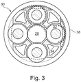
- the epicyclic gearbox 30 is shown by way of example in greater detail in Figure 3 .
- Each of the sun gear 28, planet gears 32 and ring gear 38 comprise teeth about their periphery to intermesh with the other gears. However, for clarity only exemplary portions of the teeth are illustrated in Figure 3 .
- Practical applications of a planetary epicyclic gearbox 30 generally comprise at least three planet gears 32.
- the epicyclic gearbox 30 illustrated by way of example in Figures 2 and 3 is of the planetary type, in that the planet carrier 34 is coupled to an output shaft via linkages 36, with the ring gear 38 fixed.
- the epicyclic gearbox 30 may be a star arrangement, in which the planet carrier 34 is held fixed, with the ring (or annulus) gear 38 allowed to rotate. In such an arrangement the fan 23 is driven by the ring gear 38.
- the gearbox 30 may be a differential gearbox in which the ring gear 38 and the planet carrier 34 are both allowed to rotate.
- any suitable arrangement may be used for locating the gearbox 30 in the engine 10 and/or for connecting the gearbox 30 to the engine 10.
- the connections (such as the linkages 36, 40 in the Figure 2 example) between the gearbox 30 and other parts of the engine 10 (such as the input shaft 26, the output shaft and the fixed structure 24) may have any desired degree of stiffness or flexibility.
- any suitable arrangement of the bearings between rotating and stationary parts of the engine may be used, and the disclosure is not limited to the exemplary arrangement of Figure 2 .
- the gearbox 30 has a star arrangement (described above)
- the skilled person would readily understand that the arrangement of output and support linkages and bearing locations would typically be different to that shown by way of example in Figure 2 .
- the present disclosure extends to a gas turbine engine having any arrangement of gearbox styles (for example star or planetary), support structures, input and output shaft arrangement, and bearing locations.
- gearbox styles for example star or planetary
- support structures for example star or planetary
- input and output shaft arrangement for example star or planetary
- bearing locations for example star or planetary
- the gearbox may drive additional and/or alternative components (e.g. the intermediate pressure compressor and/or a booster compressor).
- additional and/or alternative components e.g. the intermediate pressure compressor and/or a booster compressor.
- gas turbine engines to which the present disclosure may be applied may have alternative configurations.
- such engines may have an alternative number of compressors and/or turbines and/or an alternative number of interconnecting shafts.
- the gas turbine engine shown in Figure 1 has a split flow nozzle 20, 22 meaning that the flow through the bypass duct 22 has its own nozzle that is separate to and radially outside the core engine nozzle 20.
- this is not limiting, and any aspect of the present disclosure may also apply to engines in which the flow through the bypass duct 22 and the flow through the core 11 are mixed, or combined, before (or upstream of) a single nozzle, which may be referred to as a mixed flow nozzle.
- One or both nozzles may have a fixed or variable area.
- the described example relates to a turbofan engine, the disclosure may apply, for example, to any type of gas turbine engine, such as an open rotor (in which the fan stage is not surrounded by a nacelle) or turboprop engine, for example.
- the gas turbine engine 10 may not comprise a gearbox 30.
- the geometry of the gas turbine engine 10, and components thereof, is defined by a conventional axis system, comprising an axial direction (which is aligned with the rotational axis 9), a radial direction (in the bottom-to-top direction in Figure 1 ), and a circumferential direction (perpendicular to the page in the Figure 1 view).
- the axial, radial and circumferential directions are mutually perpendicular.
- the gas turbine engine 10 may comprise one or more strain gauges located on one or more of the blades (e.g. the blades of the high pressure compressor 15), vanes (not shown), discs (not shown) or casings.
- the cement mounting the strain gauge to the blade must be able to withstand the high temperatures >900°C experienced in the hot sections.
- a cement suitable for mounting the strain gauge is prepared as follows.
- Part A of the cementious composition is prepared by adding 200g of aluminium phosphate basic to refluxing concentrated phosphoric acid (260mL) and distilled water (200mL) over 30 minutes until a clear, viscous solution of mono aluminium phosphate stock solution was produced. This solution was allowed to cool.
- Part B of the cementious composition was prepared by ball-milling 164g of silica flour, 36g of titanium dioxide, 14g of chromium oxide, 5g or fused silica and 5g of barium oxide for 30 minutes.
- part B was added to 6.75g of the combined parts A and C and stirred until a homogenous paste was formed.
- Three layers of the mixed cement composition was applied to a component using a brush and then cured using the following cure cycle: 30 minutes air dry and ambient temperature, 30 minutes at 90°C, 20 minutes at 120°C, 1 hour at 400°C and a final post-cure at 600°C for 1 hour.
Landscapes
- Chemical & Material Sciences (AREA)
- Engineering & Computer Science (AREA)
- Ceramic Engineering (AREA)
- Materials Engineering (AREA)
- Organic Chemistry (AREA)
- Structural Engineering (AREA)
- Chemical Kinetics & Catalysis (AREA)
- Inorganic Chemistry (AREA)
- General Engineering & Computer Science (AREA)
- Mechanical Engineering (AREA)
- Combustion & Propulsion (AREA)
- Civil Engineering (AREA)
- Structures Of Non-Positive Displacement Pumps (AREA)
Abstract
The present disclosure relates to a cementious composition (e.g. for mounting a strain gauge within a gas turbine engine) comprising: part A comprising an acidic solution of a metal salt; part B comprising silica and one or more metal oxides; and part C comprising colloidal silica and/or a silicate solution. Part A may comprise an acidic aluminium phosphate solution. Part B may comprise one or more or all of titanium oxide, chromium oxide, alumina and barium oxide
Description
- The present disclosure relates to a cement composition. In particular, the disclosure relates to a cement composition for forming a cement for use in high temperature environments such as in a gas turbine engine.
- There are many high temperature environments where bonding of components is required. For example, strain gauges are often installed on various gas turbine engine structures (both static and moving) such as blades, vanes, discs and casings in order to monitor strain levels. When mounted in hot sections of a gas turbine engine (e.g. in the compressor and turbine sections), temperatures can reach up to 900°C and thus the cement used to bond the strain gauges in these hot sections needs to be able to withstand the high temperature environments. Cements for bonding strain gauges also need to be electrically insulating in order to isolate the strain gauges from any conductive material to allow them to obtain an accurate resistance and therefore strain measurement.
- Bonding cements for components such as lead-out wiring needs to be able to withstand even higher temperatures e.g. in excess of 1300°C.
- Such cements also need to be able to withstand the high centrifugal forces experienced in some locations within the gas turbine engine e.g. on high pressure turbine blades.
- There are currently commercially available high temperature cements but these contain ammonium dichromate which is a carcinogenic compound and which is being phased out under the REACH legislation
- There exists the need for a new cement formulation that can withstand high temperature environments and harsh conditions and that does not contain ammonium dichromate.
- According to a first aspect there is provided a cementious composition comprising:
- part A comprising an acidic solution of a metal salt;
- part B comprising silica and one or more metal oxides; and
- part C comprising colloidal silica and/or a silicate solution.
- The present inventors have found that a cement formed from such a cementious composition can withstand the very high temperatures and harsh environments found in hot sections of a gas turbine engine. The composition does not contain carcinogenic ammonium dichromate. In addition, the metal oxide content may be higher than in known compositions giving the resulting cement a similar coefficient of expansion to the underlying metal component.
- Optional features will now be set out. These are applicable singly or in any combination with any aspect.
- Part A comprises an acidic solution of a metal salt. The acidic solution may have a pH of less than 2.
- The metal in the metal salt may be aluminium. The metal in the metal salt may be boron.
- The salt in the metal salt may be phosphate.
- The solution may be obtained by mixing (e.g. refluxing) the metal salt with a strong acid (e.g. having a pH<2 such as pH 1) and water. The strong acid may be phosphoric acid.
- The acidic solution of a metal salt may be mono aluminium phosphate solution.
- Part B comprises silica. In some embodiments, the silica is silica flour or silica sand. The silica may have a particle size of between 10 to 100 microns.
- The silica (e.g. the silica flour/sand) can be used in an amount greater than 20 wt% e.g. greater than 30 or 40 wt%. The silica (e.g. the silica flour/sand) may make up the majority (i.e. greater than 50 wt%) of part B. For example, the silica may make up greater than 60 wt% e.g. greater than 70 wt% of part B.
- In some embodiment, the silica is used in an amount of less than 90 wt% e.g. less than 80 wt%.
- In some embodiments, the silica is used in an amount between 70 and 80 wt%.
- The one or more metal oxide(s) in part B may include one or more oxides of a transition metal e.g. one or more oxides of one or more of titanium (e.g. titanium oxide/titanium dioxide), chromium (e.g. chromium oxide/dioxide), and/or zirconium (e.g. zirconium oxide/zirconium dioxide).
- The one or more metal oxides may include aluminium oxide (e.g. alumina or fused alumina).
- The one or more metal oxides may include one or more alkaline earth metal oxides. For example, the one or more metal oxides may include oxides of one or more of barium (e.g. barium oxide), calcium (e.g. calcium oxide) and/or magnesium (e.g. magnesium oxide).
- In some embodiments, part B comprises a mixture of two or more metal oxides e.g. three or more metal oxides such as four metal oxides.
- In some embodiments, part B comprises two or more (e.g. three or four) metal oxides selected from the group consisting of transition metal oxides, aluminium oxide, and alkaline earth metal oxides.
- In some embodiments, part B comprises two or more transition metal oxides e.g. titanium dioxide and chromium oxide. The transition metal oxide(s) may make up the majority (i.e. greater than 50 wt%) of the metal oxides used in part B. The transition metal oxide(s) may make up greater than 60 wt%, e.g. greater than 70 or 80 wt% of the metal oxides used in part B.
- Titanium dioxide may make up the majority (i.e. greater than 50 wt%) of the metal oxides used in part B. Titanium dioxide may make up to 60 wt% of the metal oxides used in part B.
- In some embodiments, part B comprises the combination of one or more transition metal oxide (e.g. titanium dioxide and/or chromium oxide) with an alkaline earth metal oxide (e.g. barium oxide) and/or alumina.
- In some embodiments, part B comprises the combination of one or more transition metal oxide (e.g. titanium dioxide and/or chromium oxide) with an alkaline earth metal oxide (e.g. barium oxide) and alumina.
- In some embodiments, part B comprises the combination of two transition metal oxides (e.g. titanium dioxide and chromium oxide) with an alkaline earth metal oxide (e.g. barium oxide) and/or alumina.
- In some embodiments, part B comprises the combination of two transition metal oxides (e.g. titanium dioxide and chromium oxide) with an alkaline earth metal oxide (e.g. barium oxide) and alumina.
- The alumina and alkaline earth metal oxide (e.g. barium oxide) may be in a 1:1 wt% amount ratio.
- Part B may be formed by ball-milling the silica (flour/sand) and metal oxide(s) together.
- Part B could additionally include an electrically insulating additive e.g. boron nitride. The electrically insulating additive may be added in an amount up to 60 wt%.
- Part C may comprise colloidal silica which is an aqueous dispersion of silica such as that commercially available from Monsanto as Syton® X30.
- Part C may comprise a silicate solution such as potassium or sodium silicate solution.
- In a second aspect, there is provided a cement formed by mixing parts A, B and C of the cementious composition of the first aspect.
- In some embodiments, the cement is formed by pre-mixing parts A and C and then adding part B.
- In some embodiments, the cement is formed by mixing parts A and C in a ratio of between 1.5:10 and 4.5:10 (v/v) e.g. in a 3:10 (v/v) ratio and then adding part B.
- In some embodiments, the cement is formed by mixing parts A and C and then adding 55-65wt% (e.g. around 60 wt%) of part B to 45-35wt% (e.g. around 40wt%) of the combined parts A and C.
- In some embodiments, the cement is formed by curing said cement after mixing of parts A, B and C. In some embodiments, curing said cement comprises a plurality of curing periods wherein each successive curing period is at a higher temperature than the previous curing period. For example, there may be a first curing period at ambient temperature followed by a second curing period at a higher temperature. There may be further curing periods at further higher temperatures. The length of the curing period(s) at higher temperatures may be greater than the curing period at ambient temperature.
- In a third aspect there is a method of bonding a first component and a second component said method comprising: preparing a cement by mixing parts A, B and C of the cementious composition of the first aspect, applying the cement to at least one of the first and second components, abutting the components to allow the cement to bond them together.
- In some embodiments, the method comprises pre-mixing parts A and C and then adding part B.
- In some embodiments, the method comprises mixing parts A and C in a ratio of between 1.5:10 and 4.5:10 (v/v) e.g. in a 3:10 (v/v) ratio and then adding part B.
- In some embodiments, the method comprises mixing parts A and C and then adding 55-65wt% (e.g. around 60 wt%) of part B to 45-35wt% (e.g. around 40wt%) of the combined parts A and C.
- In some embodiments, the method comprises applying the cement to the first component, curing said cement and affixing the second component to the first.
- In some embodiments, the method comprises a plurality of curing periods wherein each successive curing period is at a higher temperature than the previous curing period. For example, there may be a first curing period at ambient temperature followed by a second curing period at a higher temperature. There may be further curing periods at further higher temperatures. The length of the curing period(s) at higher temperatures may be greater than the curing period at ambient temperature.
- In some embodiments, the method comprises applying one or more further layers of the cement and curing each layer prior to affixing the second component.
- In some embodiments, the method comprises applying one or more top layers of cement over the second component and curing the cement (e.g. curing as described above).
- In some embodiments, the first component is selected from a blade, vane, disc and casing. In some embodiments, the second component is selected from a strain gauge and a lead-out wiring.
- In a fourth aspect, there is provided a gas turbine engine comprising a first component and a second component, wherein the first and second components are bonded together using the cementious composition of the first aspect/the cement of the second aspect/the method of the third aspect.
- In some embodiments, the first component is selected from a blade, vane, disc and casing. In some embodiments, the second component is selected from a strain gauge and a lead-out wiring.
- Accordingly, the present disclosure may relate to a gas turbine engine. Such a gas turbine engine may comprise an engine core comprising a turbine, a combustor, a compressor, and a core shaft connecting the turbine to the compressor. Such a gas turbine engine may comprise a fan (having fan blades) located upstream of the engine core.
- Arrangements of the present disclosure may be particularly, although not exclusively, beneficial for fans that are driven via a gearbox. Accordingly, the gas turbine engine may comprise a gearbox that receives an input from the core shaft and outputs drive to the fan so as to drive the fan at a lower rotational speed than the core shaft. The input to the gearbox may be directly from the core shaft, or indirectly from the core shaft, for example via a spur shaft and/or gear. The core shaft may rigidly connect the turbine and the compressor, such that the turbine and compressor rotate at the same speed (with the fan rotating at a lower speed).
- The gas turbine engine as described and/or claimed herein may have any suitable general architecture. For example, the gas turbine engine may have any desired number of shafts that connect turbines and compressors, for example one, two or three shafts. Purely by way of example, the turbine connected to the core shaft may be a first turbine, the compressor connected to the core shaft may be a first compressor, and the core shaft may be a first core shaft. The engine core may further comprise a second turbine, a second compressor, and a second core shaft connecting the second turbine to the second compressor. The second turbine, second compressor, and second core shaft may be arranged to rotate at a higher rotational speed than the first core shaft.
- In such an arrangement, the second compressor may be positioned axially downstream of the first compressor. The second compressor may be arranged to receive (for example directly receive, for example via a generally annular duct) flow from the first compressor.
- The gearbox may be arranged to be driven by the core shaft that is configured to rotate (for example in use) at the lowest rotational speed (for example the first core shaft in the example above). For example, the gearbox may be arranged to be driven only by the core shaft that is configured to rotate (for example in use) at the lowest rotational speed (for example only be the first core shaft, and not the second core shaft, in the example above). Alternatively, the gearbox may be arranged to be driven by any one or more shafts, for example the first and/or second shafts in the example above.
- In any gas turbine engine as described and/or claimed herein, a combustor may be provided axially downstream of the fan and compressor(s). For example, the combustor may be directly downstream of (for example at the exit of) the second compressor, where a second compressor is provided. By way of further example, the flow at the exit to the combustor may be provided to the inlet of the second turbine, where a second turbine is provided. The combustor may be provided upstream of the turbine(s).
- The or each compressor (for example the first compressor and second compressor as described above) may comprise any number of stages, for example multiple stages. Each stage may comprise a row of rotor blades and a row of stator vanes, which may be variable stator vanes (in that their angle of incidence may be variable). The row of rotor blades and the row of stator vanes may be axially offset from each other.
- The or each turbine (for example the first turbine and second turbine as described above) may comprise any number of stages, for example multiple stages. Each stage may comprise a row of rotor blades and a row of stator vanes. The row of rotor blades and the row of stator vanes may be axially offset from each other.
- Each fan blade may be defined as having a radial span extending from a root (or hub) at a radially inner gas-washed location, or 0% span position, to a tip at a 100% span position. The ratio of the radius of the fan blade at the hub to the radius of the fan blade at the tip may be less than (or on the order of) any of: 0.4, 0.39, 0.38 0.37, 0.36, 0.35, 0.34, 0.33, 0.32, 0.31, 0.3, 0.29, 0.28, 0.27, 0.26, or 0.25. The ratio of the radius of the fan blade at the hub to the radius of the fan blade at the tip may be in an inclusive range bounded by any two of the values in the previous sentence (i.e. the values may form upper or lower bounds). These ratios may commonly be referred to as the hub-to-tip ratio. The radius at the hub and the radius at the tip may both be measured at the leading edge (or axially forwardmost) part of the blade. The hub-to-tip ratio refers, of course, to the gas-washed portion of the fan blade, i.e. the portion radially outside any platform.
- The radius of the fan may be measured between the engine centreline and the tip of a fan blade at its leading edge. The fan diameter (which may simply be twice the radius of the fan) may be greater than (or on the order of) any of: 250 cm (around 100 inches), 260 cm, 270 cm (around 105 inches), 280 cm (around 110 inches), 290 cm (around 115 inches), 300 cm (around 120 inches), 310 cm, 320 cm (around 125 inches), 330 cm (around 130 inches), 340 cm (around 135 inches), 350cm, 360cm (around 140 inches), 370 cm (around 145 inches), 380 (around 150 inches) cm or 390 cm (around 155 inches). The fan diameter may be in an inclusive range bounded by any two of the values in the previous sentence (i.e. the values may form upper or lower bounds).
- The rotational speed of the fan may vary in use. Generally, the rotational speed is lower for fans with a higher diameter. Purely by way of non-limitative example, the rotational speed of the fan at cruise conditions may be less than 2500 rpm, for example less than 2300 rpm. Purely by way of further non-limitative example, the rotational speed of the fan at cruise conditions for an engine having a fan diameter in the range of from 250 cm to 300 cm (for example 250 cm to 280 cm) may be in the range of from 1700 rpm to 2500 rpm, for example in the range of from 1800 rpm to 2300 rpm, for example in the range of from 1900 rpm to 2100 rpm. Purely by way of further non-limitative example, the rotational speed of the fan at cruise conditions for an engine having a fan diameter in the range of from 320 cm to 380 cm may be in the range of from 1200 rpm to 2000 rpm, for example in the range of from 1300 rpm to 1800 rpm, for example in the range of from 1400 rpm to 1600 rpm.
- In use of the gas turbine engine, the fan (with associated fan blades) rotates about a rotational axis. This rotation results in the tip of the fan blade moving with a velocity Utip. The work done by the fan blades 13 on the flow results in an enthalpy rise dH of the flow. A fan tip loading may be defined as dH/Utip 2, where dH is the enthalpy rise (for example the 1-D average enthalpy rise) across the fan and Utip is the (translational) velocity of the fan tip, for example at the leading edge of the tip (which may be defined as fan tip radius at leading edge multiplied by angular speed). The fan tip loading at cruise conditions may be greater than (or on the order of) any of: 0.3, 0.31, 0.32, 0.33, 0.34, 0.35, 0.36, 0.37, 0.38, 0.39 or 0.4 (all units in this paragraph being Jkg-1K-1/(ms-1)2). The fan tip loading may be in an inclusive range bounded by any two of the values in the previous sentence (i.e. the values may form upper or lower bounds).
- Gas turbine engines in accordance with the present disclosure may have any desired bypass ratio, where the bypass ratio is defined as the ratio of the mass flow rate of the flow through the bypass duct to the mass flow rate of the flow through the core at cruise conditions. In some arrangements the bypass ratio may be greater than (or on the order of) any of the following: 10, 10.5, 11, 11.5, 12, 12.5, 13, 13.5, 14, 14.5, 15, 15.5, 16, 16.5, or 17. The bypass ratio may be in an inclusive range bounded by any two of the values in the previous sentence (i.e. the values may form upper or lower bounds). The bypass duct may be substantially annular. The bypass duct may be radially outside the core engine. The radially outer surface of the bypass duct may be defined by a nacelle and/or a fan case.
- The overall pressure ratio of a gas turbine engine as described and/or claimed herein may be defined as the ratio of the stagnation pressure upstream of the fan to the stagnation pressure at the exit of the highest pressure compressor (before entry into the combustor). By way of non-limitative example, the overall pressure ratio of a gas turbine engine as described and/or claimed herein at cruise may be greater than (or on the order of) any of the following: 35, 40, 45, 50, 55, 60, 65, 70, 75. The overall pressure ratio may be in an inclusive range bounded by any two of the values in the previous sentence (i.e. the values may form upper or lower bounds).
- Specific thrust of an engine may be defined as the net thrust of the engine divided by the total mass flow through the engine. At cruise conditions, the specific thrust of an engine described and/or claimed herein may be less than (or on the order of) any of the following: 110 Nkg-1s, 105 Nkg-1s, 100 Nkg-1s, 95 Nkg-1s, 90 Nkg-1s, 85 Nkg-1s or 80 Nkg-1s. The specific thrust may be in an inclusive range bounded by any two of the values in the previous sentence (i.e. the values may form upper or lower bounds). Such engines may be particularly efficient in comparison with conventional gas turbine engines.
- A gas turbine engine as described and/or claimed herein may have any desired maximum thrust. Purely by way of non-limitative example, a gas turbine as described and/or claimed herein may be capable of producing a maximum thrust of at least (or on the order of) any of the following: 160kN, 170kN, 180kN, 190kN, 200kN, 250kN, 300kN, 350kN, 400kN, 450kN, 500kN, or 550kN. The maximum thrust may be in an inclusive range bounded by any two of the values in the previous sentence (i.e. the values may form upper or lower bounds). The thrust referred to above may be the maximum net thrust at standard atmospheric conditions at sea level plus 15 deg C (ambient pressure 101.3kPa,
temperature 30 deg C), with the engine static. - In use, the temperature of the flow at the entry to the high pressure turbine may be particularly high. This temperature, which may be referred to as TET, may be measured at the exit to the combustor, for example immediately upstream of the first turbine vane, which itself may be referred to as a nozzle guide vane. At cruise, the TET may be at least (or on the order of) any of the following: 1400K, 1450K, 1500K, 1550K, 1600K or 1650K. The TET at cruise may be in an inclusive range bounded by any two of the values in the previous sentence (i.e. the values may form upper or lower bounds). The maximum TET in use of the engine may be, for example, at least (or on the order of) any of the following: 1700K, 1750K, 1800K, 1850K, 1900K, 1950K or 2000K. The maximum TET may be in an inclusive range bounded by any two of the values in the previous sentence (i.e. the values may form upper or lower bounds). The maximum TET may occur, for example, at a high thrust condition, for example at a maximum take-off (MTO) condition.
- A fan blade and/or aerofoil portion of a fan blade described herein may be manufactured from any suitable material or combination of materials. For example at least a part of the fan blade and/or aerofoil may be manufactured at least in part from a composite, for example a metal matrix composite and/or an organic matrix composite, such as carbon fibre. By way of further example at least a part of the fan blade and/or aerofoil may be manufactured at least in part from a metal, such as a titanium based metal or an aluminium based material (such as an aluminium-lithium alloy) or a steel based material. The fan blade may comprise at least two regions manufactured using different materials. For example, the fan blade may have a protective leading edge, which may be manufactured using a material that is better able to resist impact (for example from birds, ice or other material) than the rest of the blade. Such a leading edge may, for example, be manufactured using titanium or a titanium-based alloy. Thus, purely by way of example, the fan blade may have a carbon-fibre or aluminium based body (such as an aluminium lithium alloy) with a titanium leading edge.
- A fan as described herein may comprise a central portion, from which the fan blades may extend, for example in a radial direction. The fan blades may be attached to the central portion in any desired manner. For example, each fan blade may comprise a fixture which may engage a corresponding slot in the hub (or disc). Purely by way of example, such a fixture may be in the form of a dovetail that may slot into and/or engage a corresponding slot in the hub/disc in order to fix the fan blade to the hub/disc. By way of further example, the fan blades maybe formed integrally with a central portion. Such an arrangement may be referred to as a blisk or a bling. Any suitable method may be used to manufacture such a blisk or bling. For example, at least a part of the fan blades may be machined from a block and/or at least part of the fan blades may be attached to the hub/disc by welding, such as linear friction welding.
- The gas turbine engines described and/or claimed herein may or may not be provided with a variable area nozzle (VAN). Such a variable area nozzle may allow the exit area of the bypass duct to be varied in use. The general principles of the present disclosure may apply to engines with or without a VAN.
- The fan of a gas turbine as described and/or claimed herein may have any desired number of fan blades, for example 16, 18, 20, or 22 fan blades.
- As used herein, cruise conditions may mean cruise conditions of an aircraft to which the gas turbine engine is attached. Such cruise conditions may be conventionally defined as the conditions at mid-cruise, for example the conditions experienced by the aircraft and/or engine at the midpoint (in terms of time and/or distance) between top of climb and start of decent.
- Purely by way of example, the forward speed at the cruise condition may be any point in the range of from Mach 0.7 to 0.9, for example 0.75 to 0.85, for example 0.76 to 0.84, for example 0.77 to 0.83, for example 0.78 to 0.82, for example 0.79 to 0.81, for example on the order of Mach 0.8, on the order of Mach 0.85 or in the range of from 0.8 to 0.85. Any single speed within these ranges may be the cruise condition. For some aircraft, the cruise conditions may be outside these ranges, for example below Mach 0.7 or above Mach 0.9.
- Purely by way of example, the cruise conditions may correspond to standard atmospheric conditions at an altitude that is in the range of from 10000m to 15000m, for example in the range of from 10000m to 12000m, for example in the range of from 10400m to 11600m (around 38000 ft), for example in the range of from 10500m to 11500m, for example in the range of from 10600m to 11400m, for example in the range of from 10700m (around 35000 ft) to 11300m, for example in the range of from 10800m to 11200m, for example in the range of from 10900m to 11100m, for example on the order of 11000m. The cruise conditions may correspond to standard atmospheric conditions at any given altitude in these ranges.
- Purely by way of example, the cruise conditions may correspond to: a forward Mach number of 0.8; a pressure of 23000 Pa; and a temperature of -55 deg C.
- As used anywhere herein, "cruise" or "cruise conditions" may mean the aerodynamic design point. Such an aerodynamic design point (or ADP) may correspond to the conditions (comprising, for example, one or more of the Mach Number, environmental conditions and thrust requirement) for which the fan is designed to operate. This may mean, for example, the conditions at which the fan (or gas turbine engine) is designed to have optimum efficiency.
- In use, a gas turbine engine described and/or claimed herein may operate at the cruise conditions defined elsewhere herein. Such cruise conditions may be determined by the cruise conditions (for example the mid-cruise conditions) of an aircraft to which at least one (for example 2 or 4) gas turbine engine may be mounted in order to provide propulsive thrust.
- The skilled person will appreciate that except where mutually exclusive, a feature or parameter described in relation to any one of the above aspects may be applied to any other aspect. Furthermore, except where mutually exclusive, any feature or parameter described herein may be applied to any aspect and/or combined with any other feature or parameter described herein.
- Embodiments will now be described by way of example only, with reference to the Figures, in which:
-
Figure 1 is a sectional side view of a gas turbine engine; -
Figure 2 is a close up sectional side view of an upstream portion of a gas turbine engine; and -
Figure 3 is a partially cut-away view of a gearbox for a gas turbine engine. -
Figure 1 illustrates agas turbine engine 10 having a principalrotational axis 9. Theengine 10 comprises anair intake 12 and apropulsive fan 23 that generates two airflows: a core airflow A and a bypass airflow B. Thegas turbine engine 10 comprises a core 11 that receives the core airflow A. Theengine core 11 comprises, in axial flow series, alow pressure compressor 14, a high-pressure compressor 15,combustion equipment 16, a high-pressure turbine 17, alow pressure turbine 19 and acore exhaust nozzle 20. Anacelle 21 surrounds thegas turbine engine 10 and defines abypass duct 22 and abypass exhaust nozzle 18. The bypass airflow B flows through thebypass duct 22. Thefan 23 is attached to and driven by thelow pressure turbine 19 via ashaft 26. - In use, the core airflow A is accelerated and compressed by the
low pressure compressor 14 and directed into thehigh pressure compressor 15 where further compression takes place. The compressed air exhausted from thehigh pressure compressor 15 is directed into thecombustion system 16 where it is mixed with fuel and the mixture is combusted. The resultant hot combustion products then expand through, and thereby drive, the high pressure andlow pressure turbines nozzle 20 to provide some propulsive thrust. Thehigh pressure turbine 17 drives thehigh pressure compressor 15 by a suitable interconnectingshaft 27. Thefan 23 generally provides the majority of the propulsive thrust. - Arrangements of the present disclosure may be particularly, although not exclusively, beneficial for
fans 23 that are driven via agearbox 30. Accordingly, the gas turbine engine may comprise agearbox 30 that receives an input from thecore shaft 26 and outputs drive to thefan 23 so as to drive thefan 23 at a lower rotational speed than thecore shaft 26. The input to thegearbox 30 may be directly from thecore shaft 26, or indirectly from thecore shaft 26, for example via a spur shaft and/or gear. - An exemplary arrangement for a geared fan
gas turbine engine 10 is shown inFigure 2 . The low pressure turbine 19 (seeFigure 1 ) drives theshaft 26, which is coupled to a sun wheel, or sun gear, 28 of theepicyclic gear arrangement 30. Radially outwardly of thesun gear 28 and intermeshing therewith is a plurality of planet gears 32 that are coupled together by aplanet carrier 34. Theplanet carrier 34 constrains the planet gears 32 to precess around thesun gear 28 in synchronicity whilst enabling eachplanet gear 32 to rotate about its own axis. Theplanet carrier 34 is coupled vialinkages 36 to thefan 23 in order to drive its rotation about theengine axis 9. Radially outwardly of the planet gears 32 and intermeshing therewith is an annulus orring gear 38 that is coupled, vialinkages 40, to a stationary supportingstructure 24. - Note that the terms "low pressure turbine" and "low pressure compressor" as used herein may be taken to mean the lowest pressure turbine stages and lowest pressure compressor stages (i.e. not including the fan 23) respectively and/or the turbine and compressor stages that are connected together by the interconnecting
shaft 26 with the lowest rotational speed in the engine (i.e. not including the gearbox output shaft that drives the fan 23). In some literature, the "low pressure turbine" and "low pressure compressor" referred to herein may alternatively be known as the "intermediate pressure turbine" and "intermediate pressure compressor". Where such alternative nomenclature is used, thefan 23 may be referred to as a first, or lowest pressure, compression stage. - The
epicyclic gearbox 30 is shown by way of example in greater detail inFigure 3 . Each of thesun gear 28, planet gears 32 andring gear 38 comprise teeth about their periphery to intermesh with the other gears. However, for clarity only exemplary portions of the teeth are illustrated inFigure 3 . There are fourplanet gears 32 illustrated, although it will be apparent to the skilled reader that more or fewer planet gears 32 may be provided within the scope of the claimed invention. Practical applications of a planetaryepicyclic gearbox 30 generally comprise at least three planet gears 32. - The
epicyclic gearbox 30 illustrated by way of example inFigures 2 and3 is of the planetary type, in that theplanet carrier 34 is coupled to an output shaft vialinkages 36, with thering gear 38 fixed. However, any other suitable type ofepicyclic gearbox 30 may be used. By way of further example, theepicyclic gearbox 30 may be a star arrangement, in which theplanet carrier 34 is held fixed, with the ring (or annulus)gear 38 allowed to rotate. In such an arrangement thefan 23 is driven by thering gear 38. By way of further alternative example, thegearbox 30 may be a differential gearbox in which thering gear 38 and theplanet carrier 34 are both allowed to rotate. - It will be appreciated that the arrangement shown in
Figures 2 and3 is by way of example only, and various alternatives are within the scope of the present disclosure. Purely by way of example, any suitable arrangement may be used for locating thegearbox 30 in theengine 10 and/or for connecting thegearbox 30 to theengine 10. By way of further example, the connections (such as thelinkages Figure 2 example) between thegearbox 30 and other parts of the engine 10 (such as theinput shaft 26, the output shaft and the fixed structure 24) may have any desired degree of stiffness or flexibility. By way of further example, any suitable arrangement of the bearings between rotating and stationary parts of the engine (for example between the input and output shafts from the gearbox and the fixed structures, such as the gearbox casing) may be used, and the disclosure is not limited to the exemplary arrangement ofFigure 2 . For example, where thegearbox 30 has a star arrangement (described above), the skilled person would readily understand that the arrangement of output and support linkages and bearing locations would typically be different to that shown by way of example inFigure 2 . - Accordingly, the present disclosure extends to a gas turbine engine having any arrangement of gearbox styles (for example star or planetary), support structures, input and output shaft arrangement, and bearing locations.
- Optionally, the gearbox may drive additional and/or alternative components (e.g. the intermediate pressure compressor and/or a booster compressor).
- Other gas turbine engines to which the present disclosure may be applied may have alternative configurations. For example, such engines may have an alternative number of compressors and/or turbines and/or an alternative number of interconnecting shafts. By way of further example, the gas turbine engine shown in
Figure 1 has asplit flow nozzle bypass duct 22 has its own nozzle that is separate to and radially outside thecore engine nozzle 20. However, this is not limiting, and any aspect of the present disclosure may also apply to engines in which the flow through thebypass duct 22 and the flow through the core 11 are mixed, or combined, before (or upstream of) a single nozzle, which may be referred to as a mixed flow nozzle. One or both nozzles (whether mixed or split flow) may have a fixed or variable area. Whilst the described example relates to a turbofan engine, the disclosure may apply, for example, to any type of gas turbine engine, such as an open rotor (in which the fan stage is not surrounded by a nacelle) or turboprop engine, for example. In some arrangements, thegas turbine engine 10 may not comprise agearbox 30. - The geometry of the
gas turbine engine 10, and components thereof, is defined by a conventional axis system, comprising an axial direction (which is aligned with the rotational axis 9), a radial direction (in the bottom-to-top direction inFigure 1 ), and a circumferential direction (perpendicular to the page in theFigure 1 view). The axial, radial and circumferential directions are mutually perpendicular. - The
gas turbine engine 10 may comprise one or more strain gauges located on one or more of the blades (e.g. the blades of the high pressure compressor 15), vanes (not shown), discs (not shown) or casings. - Where a strain gauge is mounted on a blade of the high pressure compressor 15 (or indeed anywhere else in the hot sections of the gas turbine engine), the cement mounting the strain gauge to the blade must be able to withstand the high temperatures >900°C experienced in the hot sections.
- A cement suitable for mounting the strain gauge is prepared as follows.
- Part A of the cementious composition is prepared by adding 200g of aluminium phosphate basic to refluxing concentrated phosphoric acid (260mL) and distilled water (200mL) over 30 minutes until a clear, viscous solution of mono aluminium phosphate stock solution was produced. This solution was allowed to cool.
- Part B of the cementious composition was prepared by ball-milling 164g of silica flour, 36g of titanium dioxide, 14g of chromium oxide, 5g or fused silica and 5g of barium oxide for 30 minutes.
- Next the cooled mono aluminium phosphate stock solution (part A) was mixed in a ratio of 3:10 (v/v) with colloidal silica (Syton® X 30) (part C).
- Then 10g of part B was added to 6.75g of the combined parts A and C and stirred until a homogenous paste was formed.
- Three layers of the mixed cement composition was applied to a component using a brush and then cured using the following cure cycle: 30 minutes air dry and ambient temperature, 30 minutes at 90°C, 20 minutes at 120°C, 1 hour at 400°C and a final post-cure at 600°C for 1 hour.
- It will be understood that the disclosure is not limited to the embodiments above-described and various modifications and improvements can be made without departing from the concepts described herein. Except where mutually exclusive, any of the features may be employed separately or in combination with any other features and the disclosure extends to and includes all combinations and sub-combinations of one or more features described herein.
Claims (20)
- A cementious composition comprising:part A comprising an acidic solution of a metal salt;part B comprising silica and one or more metal oxides; andpart C comprising colloidal silica and/or a silicate solution.
- A composition according to claim 1 wherein the metal salt is an aluminium salt.
- A composition according to claim 2 wherein part A comprises an acidic aluminium phosphate solution.
- A composition according to any one of the preceding claims wherein part B comprises silica having a particle size of between 10 to 100 microns.
- A composition according to any one of the preceding claims wherein part B comprises silica in an amount between 70 and 80 wt%.
- A composition according to any one of the preceding claims wherein part B comprises one or more metal oxides selected from the group consisting of transition metal oxides, aluminium oxide, and/or alkaline earth metal oxides.
- A composition according to claim 6 wherein part B comprises a mixture of two or more metal oxides.
- A composition according to claim 7 wherein part B comprises the combination of one or more transition metal oxide with an alkaline earth metal oxide and/or alumina.
- A composition according to claim 8 wherein part B comprises the combination of one or more transition metal oxide with an alkaline earth metal oxide and alumina.
- A composition according to claim 8 or 9 wherein part B comprises two transition metal oxides.
- A composition according to any one of claims 6 to 10 wherein part B comprises one or more or all of titanium oxide, chromium oxide, alumina and barium oxide
- A composition according to any one of the preceding claims wherein part C comprises colloidal silica or a potassium or sodium silicate solution.
- A cement formed by mixing parts A, B and C of the cementious composition according to any one of the preceding claims.
- The cement of claim 13 formed by mixing parts A and C in a ratio of between 1.5:10 and 4.5:10 (v/v) and then adding part B.
- The cement of claim 14 formed by mixing parts A and C and then adding 55-65wt% of part B.
- A method of bonding a first component and a second component said method comprising: preparing a cement according to any one of claims 13 to 15, applying the cement to at least one of the first and second components, abutting the components to allow the cement to bond them together.
- A method according to claim 16 comprising applying the cement to the first component, curing said cement and affixing the second component to the first.
- A method according to claim 17 wherein curing the cement comprises a plurality of curing periods wherein each successive curing period is at a higher temperature than the previous curing period.
- A method according to any one of claims 16 to 18 wherein the first component is selected from a blade, vane, disc and casing and the second component is selected from a strain gauge and a lead-out wiring.
- A gas turbine engine comprising a first component and a second component, wherein the first and second components are bonded together using the cementious composition of any one of claims 1 to 12, the cement of any one of claims 13 to 15 or the method of any one of claims 16 to 19.
Applications Claiming Priority (1)
| Application Number | Priority Date | Filing Date | Title |
|---|---|---|---|
| GBGB1815832.9A GB201815832D0 (en) | 2018-09-28 | 2018-09-28 | Cement |
Publications (1)
| Publication Number | Publication Date |
|---|---|
| EP3628648A1 true EP3628648A1 (en) | 2020-04-01 |
Family
ID=64108979
Family Applications (1)
| Application Number | Title | Priority Date | Filing Date |
|---|---|---|---|
| EP19196018.6A Withdrawn EP3628648A1 (en) | 2018-09-28 | 2019-09-06 | Cement |
Country Status (3)
| Country | Link |
|---|---|
| US (1) | US20200102249A1 (en) |
| EP (1) | EP3628648A1 (en) |
| GB (1) | GB201815832D0 (en) |
Citations (3)
| Publication number | Priority date | Publication date | Assignee | Title |
|---|---|---|---|---|
| GB1503934A (en) * | 1974-02-12 | 1978-03-15 | Coatings For Ind | Phosphate coating compositions containing inorganic particulate matter |
| US4659610A (en) * | 1984-03-02 | 1987-04-21 | Subtex, Inc. | Structures made using an inorganic-binder composition |
| EP2433919A1 (en) * | 2010-09-24 | 2012-03-28 | Chemische Fabrik Budenheim KG | Hardener compound |
-
2018
- 2018-09-28 GB GBGB1815832.9A patent/GB201815832D0/en not_active Ceased
-
2019
- 2019-09-06 EP EP19196018.6A patent/EP3628648A1/en not_active Withdrawn
- 2019-09-23 US US16/578,806 patent/US20200102249A1/en not_active Abandoned
Patent Citations (3)
| Publication number | Priority date | Publication date | Assignee | Title |
|---|---|---|---|---|
| GB1503934A (en) * | 1974-02-12 | 1978-03-15 | Coatings For Ind | Phosphate coating compositions containing inorganic particulate matter |
| US4659610A (en) * | 1984-03-02 | 1987-04-21 | Subtex, Inc. | Structures made using an inorganic-binder composition |
| EP2433919A1 (en) * | 2010-09-24 | 2012-03-28 | Chemische Fabrik Budenheim KG | Hardener compound |
Also Published As
| Publication number | Publication date |
|---|---|
| GB201815832D0 (en) | 2018-11-14 |
| US20200102249A1 (en) | 2020-04-02 |
Similar Documents
| Publication | Publication Date | Title |
|---|---|---|
| US11313440B2 (en) | Epicyclic gearbox | |
| EP3708819A1 (en) | A gas turbine engine for an aircraft | |
| EP3591205A1 (en) | High efficiency gas turbine engine | |
| EP3587749A1 (en) | Gas turbine engine | |
| EP3594447A1 (en) | Gas turbine engine outlet guide vanes | |
| US11268440B2 (en) | Stabilization bearing system for geared turbofan engines | |
| EP3611365A1 (en) | Device for coupling an output shaft with an epicyclic gearbox, method for coupling an output shaft with an epicyclic gearbox and a gas turbine engine | |
| EP3699406A1 (en) | Component for fastening arrangement, fastening arrangement and gas turbine engine comprising fastening arrangement | |
| EP3527802A1 (en) | A driveshaft | |
| EP3656984A1 (en) | Blade mounting | |
| EP3564482A2 (en) | Drive shaft | |
| US11879397B2 (en) | Gas turbine engine with staggered epicyclic gearbox | |
| EP3800378B1 (en) | Stiffening member for epicyclical gear system housing assembly | |
| EP3594476B1 (en) | A geared turbofan gas turbine engine mounting arrangement | |
| US11181042B2 (en) | Aircraft engine operability | |
| EP3667048A1 (en) | Planet carrier and method of assembling of a planet carrier | |
| EP3546367A1 (en) | A geared turbofan engine mount arrangement | |
| US20200003078A1 (en) | Planetary gear drive and aircraft gas turbine with a planetary gear drive | |
| EP3628648A1 (en) | Cement | |
| EP3670864A1 (en) | Connector system | |
| EP3594477A1 (en) | Apparatus for gas turbine engines | |
| EP3783214A1 (en) | Gas turbine engine | |
| EP3561231A1 (en) | Coolant channel | |
| US11834958B2 (en) | Rotor assembly | |
| EP3800379A1 (en) | Static curvic joint for epicyclical gear system housing assembly |
Legal Events
| Date | Code | Title | Description |
|---|---|---|---|
| PUAI | Public reference made under article 153(3) epc to a published international application that has entered the european phase |
Free format text: ORIGINAL CODE: 0009012 |
|
| STAA | Information on the status of an ep patent application or granted ep patent |
Free format text: STATUS: THE APPLICATION HAS BEEN PUBLISHED |
|
| AK | Designated contracting states |
Kind code of ref document: A1 Designated state(s): AL AT BE BG CH CY CZ DE DK EE ES FI FR GB GR HR HU IE IS IT LI LT LU LV MC MK MT NL NO PL PT RO RS SE SI SK SM TR |
|
| AX | Request for extension of the european patent |
Extension state: BA ME |
|
| STAA | Information on the status of an ep patent application or granted ep patent |
Free format text: STATUS: THE APPLICATION HAS BEEN WITHDRAWN |
|
| 18W | Application withdrawn |
Effective date: 20200929 |