EP3628605B2 - Method of fault prediction in a packaging machine - Google Patents
Method of fault prediction in a packaging machine Download PDFInfo
- Publication number
- EP3628605B2 EP3628605B2 EP19198553.0A EP19198553A EP3628605B2 EP 3628605 B2 EP3628605 B2 EP 3628605B2 EP 19198553 A EP19198553 A EP 19198553A EP 3628605 B2 EP3628605 B2 EP 3628605B2
- Authority
- EP
- European Patent Office
- Prior art keywords
- distribution
- measure
- data values
- independently movable
- track
- Prior art date
- Legal status (The legal status is an assumption and is not a legal conclusion. Google has not performed a legal analysis and makes no representation as to the accuracy of the status listed.)
- Active
Links
Images


Classifications
-
- B—PERFORMING OPERATIONS; TRANSPORTING
- B65—CONVEYING; PACKING; STORING; HANDLING THIN OR FILAMENTARY MATERIAL
- B65G—TRANSPORT OR STORAGE DEVICES, e.g. CONVEYORS FOR LOADING OR TIPPING, SHOP CONVEYOR SYSTEMS OR PNEUMATIC TUBE CONVEYORS
- B65G43/00—Control devices, e.g. for safety, warning or fault-correcting
- B65G43/02—Control devices, e.g. for safety, warning or fault-correcting detecting dangerous physical condition of load carriers, e.g. for interrupting the drive in the event of overheating
-
- B—PERFORMING OPERATIONS; TRANSPORTING
- B65—CONVEYING; PACKING; STORING; HANDLING THIN OR FILAMENTARY MATERIAL
- B65B—MACHINES, APPARATUS OR DEVICES FOR, OR METHODS OF, PACKAGING ARTICLES OR MATERIALS; UNPACKING
- B65B57/00—Automatic control, checking, warning, or safety devices
- B65B57/02—Automatic control, checking, warning, or safety devices responsive to absence, presence, abnormal feed, or misplacement of binding or wrapping material, containers, or packages
-
- B—PERFORMING OPERATIONS; TRANSPORTING
- B65—CONVEYING; PACKING; STORING; HANDLING THIN OR FILAMENTARY MATERIAL
- B65B—MACHINES, APPARATUS OR DEVICES FOR, OR METHODS OF, PACKAGING ARTICLES OR MATERIALS; UNPACKING
- B65B57/00—Automatic control, checking, warning, or safety devices
-
- B—PERFORMING OPERATIONS; TRANSPORTING
- B65—CONVEYING; PACKING; STORING; HANDLING THIN OR FILAMENTARY MATERIAL
- B65B—MACHINES, APPARATUS OR DEVICES FOR, OR METHODS OF, PACKAGING ARTICLES OR MATERIALS; UNPACKING
- B65B57/00—Automatic control, checking, warning, or safety devices
- B65B57/02—Automatic control, checking, warning, or safety devices responsive to absence, presence, abnormal feed, or misplacement of binding or wrapping material, containers, or packages
- B65B57/04—Automatic control, checking, warning, or safety devices responsive to absence, presence, abnormal feed, or misplacement of binding or wrapping material, containers, or packages and operating to control, or to stop, the feed of such material, containers, or packages
-
- B—PERFORMING OPERATIONS; TRANSPORTING
- B65—CONVEYING; PACKING; STORING; HANDLING THIN OR FILAMENTARY MATERIAL
- B65G—TRANSPORT OR STORAGE DEVICES, e.g. CONVEYORS FOR LOADING OR TIPPING, SHOP CONVEYOR SYSTEMS OR PNEUMATIC TUBE CONVEYORS
- B65G43/00—Control devices, e.g. for safety, warning or fault-correcting
- B65G43/04—Control devices, e.g. for safety, warning or fault-correcting detecting slip between driving element and load-carrier, e.g. for interrupting the drive
-
- B—PERFORMING OPERATIONS; TRANSPORTING
- B65—CONVEYING; PACKING; STORING; HANDLING THIN OR FILAMENTARY MATERIAL
- B65G—TRANSPORT OR STORAGE DEVICES, e.g. CONVEYORS FOR LOADING OR TIPPING, SHOP CONVEYOR SYSTEMS OR PNEUMATIC TUBE CONVEYORS
- B65G54/00—Non-mechanical conveyors not otherwise provided for
- B65G54/02—Non-mechanical conveyors not otherwise provided for electrostatic, electric, or magnetic
-
- G—PHYSICS
- G01—MEASURING; TESTING
- G01M—TESTING STATIC OR DYNAMIC BALANCE OF MACHINES OR STRUCTURES; TESTING OF STRUCTURES OR APPARATUS, NOT OTHERWISE PROVIDED FOR
- G01M99/00—Subject matter not provided for in other groups of this subclass
- G01M99/005—Testing of complete machines, e.g. washing-machines or mobile phones
-
- B—PERFORMING OPERATIONS; TRANSPORTING
- B65—CONVEYING; PACKING; STORING; HANDLING THIN OR FILAMENTARY MATERIAL
- B65G—TRANSPORT OR STORAGE DEVICES, e.g. CONVEYORS FOR LOADING OR TIPPING, SHOP CONVEYOR SYSTEMS OR PNEUMATIC TUBE CONVEYORS
- B65G2203/00—Indexing code relating to control or detection of the articles or the load carriers during conveying
- B65G2203/02—Control or detection
- B65G2203/0266—Control or detection relating to the load carrier(s)
- B65G2203/0275—Damage on the load carrier
-
- B—PERFORMING OPERATIONS; TRANSPORTING
- B65—CONVEYING; PACKING; STORING; HANDLING THIN OR FILAMENTARY MATERIAL
- B65G—TRANSPORT OR STORAGE DEVICES, e.g. CONVEYORS FOR LOADING OR TIPPING, SHOP CONVEYOR SYSTEMS OR PNEUMATIC TUBE CONVEYORS
- B65G2203/00—Indexing code relating to control or detection of the articles or the load carriers during conveying
- B65G2203/02—Control or detection
- B65G2203/0266—Control or detection relating to the load carrier(s)
- B65G2203/0283—Position of the load carrier
-
- B—PERFORMING OPERATIONS; TRANSPORTING
- B65—CONVEYING; PACKING; STORING; HANDLING THIN OR FILAMENTARY MATERIAL
- B65G—TRANSPORT OR STORAGE DEVICES, e.g. CONVEYORS FOR LOADING OR TIPPING, SHOP CONVEYOR SYSTEMS OR PNEUMATIC TUBE CONVEYORS
- B65G2207/00—Indexing codes relating to constructional details, configuration and additional features of a handling device, e.g. Conveyors
- B65G2207/48—Wear protection or indication features
-
- G—PHYSICS
- G05—CONTROLLING; REGULATING
- G05B—CONTROL OR REGULATING SYSTEMS IN GENERAL; FUNCTIONAL ELEMENTS OF SUCH SYSTEMS; MONITORING OR TESTING ARRANGEMENTS FOR SUCH SYSTEMS OR ELEMENTS
- G05B2219/00—Program-control systems
- G05B2219/30—Nc systems
- G05B2219/45—Nc applications
- G05B2219/45048—Packaging
-
- G—PHYSICS
- G05—CONTROLLING; REGULATING
- G05B—CONTROL OR REGULATING SYSTEMS IN GENERAL; FUNCTIONAL ELEMENTS OF SUCH SYSTEMS; MONITORING OR TESTING ARRANGEMENTS FOR SUCH SYSTEMS OR ELEMENTS
- G05B2219/00—Program-control systems
- G05B2219/30—Nc systems
- G05B2219/45—Nc applications
- G05B2219/45056—Handling cases, boxes
-
- G—PHYSICS
- G05—CONTROLLING; REGULATING
- G05B—CONTROL OR REGULATING SYSTEMS IN GENERAL; FUNCTIONAL ELEMENTS OF SUCH SYSTEMS; MONITORING OR TESTING ARRANGEMENTS FOR SUCH SYSTEMS OR ELEMENTS
- G05B23/00—Testing or monitoring of control systems or parts thereof
- G05B23/02—Electric testing or monitoring
- G05B23/0205—Electric testing or monitoring by means of a monitoring system capable of detecting and responding to faults
- G05B23/0218—Electric testing or monitoring by means of a monitoring system capable of detecting and responding to faults characterised by the fault detection method dealing with either existing or incipient faults
- G05B23/0224—Process history based detection method, e.g. whereby history implies the availability of large amounts of data
- G05B23/024—Quantitative history assessment, e.g. mathematical relationships between available data; Functions therefor; Principal component analysis [PCA]; Partial least square [PLS]; Statistical classifiers, e.g. Bayesian networks, linear regression or correlation analysis; Neural networks
Definitions
- the present invention generally relates to the field of condition monitoring. More particularly, the present invention relates to a method of fault prediction in a packaging machine having independently moving objects, and an apparatus for predicting fault in such packaging machine or related systems for producing sealed packages.
- Condition monitoring of machine components in production lines is critical for ensuring a desired functionality over a period of time and fault prediction.
- Monitoring distortions in the movements of machine components is an essential part in achieving the desired functionality control and prevent wear-related breakdown.
- Distortion analysis of e.g. vibrations in bearings is an important part of industrial predictive maintenance programs so that wear and damages can be discovered and repaired before the machine breaks down, thus reducing operating and maintenance costs.
- More recently conveyor systems based on linear motor technology is used for manipulating packaging containers in the manufacturing of sealed packages.
- These conveyor systems typically comprise a closed loop track, and a plurality of movable objects or carts, which are independently moved along the track by individually controlling a plurality of solenoids along the track.
- the independently movable objects or carts are controlled to engage the packaging containers in various operations.
- Systems based on such independently movable objects pose new challenges in the field of condition monitoring and fault prediction. Empirical evaluation of vibration levels is an error-prone activity that may lead to significantly underestimate or overestimate the remaining lifetime of the components.
- Previous solutions to characterize bearing faults include frequency analysis, where characteristic frequency signatures are extracted from a vibration signal.
- EP 3 373 211 A1 discloses a fault prediction method in a packaging machine, wherein features quantities of measured data associated with the motion of machine components, such as the mean, standard deviation, skewness and steepness, are calculated and compared with feature quantities previously acquired during a learning operation mode.
- an improved condition monitoring would be advantageous and in particular allowing for avoiding more of the above-mentioned problems and compromises, including providing a less complex method of fault prediction, having short execution time and thereby enabling analysis on-the-fly, thereby allowing for a less time-consuming and robust trouble-shooting of independently movable objects.
- examples of the present invention preferably seek to mitigate, alleviate or eliminate one or more deficiencies, disadvantages or issues in the art, such as the above-identified, singly or in any combination by providing a method and a system according to the appended patent claims.
- a method of fault prediction in a packaging machine having independently movable objects configured to manipulate packaging containers, the independently movable objects communicating with a control unit configured to control the positions of the independently movable objects along a track.
- the method comprises registering data values associated with the motion of the movable objects along the track with a sensor, said data values including position error values associated with a difference between a set position of a selected independently movable object on said track and an actual position of said individually movable object, determining a distribution of said data values, calculating a measure of central tendency of the data values in the distribution, calculating a quantified measure of a shape of the distribution, associating the measure of central tendency with said quantified measure of the shape as a coupled set of condition parameters, determining a degree of dispersion of a plurality of coupled sets of condition parameters associated with a plurality of motion cycles of the independently movable objects, and comparing the degree of dispersion with a dispersion threshold value, or determining a trend of the degree of dispersion over time, for said fault prediction.
- a system comprising a packaging machine and an apparatus configured to predict fault in the packaging machine.
- the packaging machine having independently movable objects configured to manipulate packaging containers.
- the independently movable objects communicating with a control unit configured to control the positions of the independently movable objects along a track.
- the apparatus comprises a sensor configured to register data values associated with the motion of the movable objects along the track, wherein the sensor is configured to register the data values as position error values associate with a difference between a set position of a selected independently movable object on the track and an actual position of the independently movable object on the track, and a processing unit configured to determine a distribution of said data values, calculate a measure of central tendency of the data values in the distribution, calculate a quantified measure of a shape of the distribution, associate the measure of central tendency with said quantified measure as a coupled set of condition parameters, determine a degree of dispersion of a plurality of coupled sets of condition parameters associated with a plurality of motion cycles of the independently movable objects, and compare the degree of dispersion with a dispersion threshold value, or determine a trend of the degree of dispersion over time, for said fault prediction.
- a computer program product comprising instructions which, when the program is executed by a computer, cause the computer to carry out the steps of the method according to the first aspect.
- Some examples of the disclosure provide for an improved method for predicting fault in machine components such as objects being independently movable on a track in packaging machine.
- Some examples of the disclosure provide for facilitated prediction of the life-time of a machine component.
- Some examples of the disclosure provide for a more predictable and efficient maintenance schedule of a machine component.
- Some examples of the disclosure provide for a method of fault prediction, having short execution time and thereby enabling analysis on-the-fly.
- Some examples of the disclosure provide for less time-consuming trouble-shooting of a machine component.
- Some examples of the disclosure provide for improved condition monitoring in a machine such in a filling machine, having a plurality of independently movable objects.
- Fig. 1 is a schematic illustration of an apparatus 200 configured to predict fault in a packaging machine 300 having independently movable objects 301 configured to manipulate packaging containers (not shown).
- the independently movable objects 301 communicate with a control unit 302 configured to control the positions of the independently movable objects 301 along a track 303.
- the track 303 may be an endless loop as exemplified in Fig. 1 .
- the track 303 is shown as an elliptic track, it is conceivable that the track 303 may have varying shapes, i.e. extending along a variety of curves with different radiuses of curvatures.
- Fig. 5a illustrates a flow chart of a related method 100 of fault prediction in a packaging machine. The order in which the steps of the method 100 are described and illustrated should not be construed as limiting and it is conceivable that the steps can be performed in varying order.
- the apparatus 200 comprises a sensor 204 configured to register 101 data values associated with the motion of the movable objects 301 along the track 303.
- Figs. 2a-c show examples of such data values versus time, i.e. a position of the independently movable objects 301 on the track (2a), a velocity of the independently movable objects 301 (2b), a position error of the independently movable objects 301 (2c), and a current supplied to the track (2d).
- the data values may comprise various other measurable characteristics of the motion of the independently movable objects 301, which can be registered by the sensor 204 for the purposes of carrying out the method 100, such as values of torque or any other force, vibration data, or acceleration associated with the movement.
- the apparatus 200 comprises a processing unit 201 configured to determine 102 a distribution of the data values and to calculate 103 a measure of central tendency of the data values in the distribution.
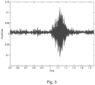
- Fig. 3 shows an example of a distribution of data values, in this case amplitude of a movement such as a vibrational movement as function of time.
- the measure of central tendency should be construed according to the normal meaning of the term within statistical theory, i.e. as a central or typical value for a probability distribution, e.g.
- the processing unit 201 is configured to calculate 104 a quantified measure of a shape of the determined distribution.
- the shape of the distribution should be construed according to the normal meaning of the term within statistical theory, i.e. describing the shape of the curvature of the distribution in Fig. 3 , such as the characteristics of the tails of such distribution, e.g. how wide or thin the tails of the distribution are, which is influenced by the number of outliers of the data points, i.e. the number of data points being far removed from the main distribution around the center of the distribution.
- the processing unit 201 is configured to associate 105 the measure of central tendency with the aforementioned quantified measure as a coupled set of condition parameters.
- a set of condition parameters is determined, where each set is a pair of data points comprising the measure of central tendency and the quantified measure of the shape of the distribution.
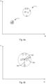
- Figs. 4a-b are schematic diagrams where each data point (small circles with solid lines) correspond to a coupled set of condition parameters.
- the quantified measure of the shape of the distribution is given on the vertical axis (K), and the measure of central tendency is given on the horizontal axis (M).
- the processing unit 201 is configured to determine 106 a degree of dispersion of a plurality of coupled sets of condition parameters associated with a plurality of motion cycles of the independently movable objects. The dispersion is indicative of how far each of the coupled sets of condition parameters are removed from eachother.
- the plurality of coupled sets of condition parameters have been determined for two points in time, t 1 and t 2 .
- the degree of dispersion is larger than at time t 1 .
- the processing unit 201 is configured to compare 107 the degree of dispersion with a dispersion threshold value, or determine 108 a trend of the degree of dispersion over time, for the fault prediction.
- An exceeded threshold value can thus be indicative of increased wear of the independently movable object 301.
- a trend of the degree of dispersion over time can be determined 108, for said fault prediction. For example, a trend of increased dispersion, going from t 1 to t 2 , can be indicative of increased wear of the independently movable object 301.
- the apparatus 200 and related method 100 provides for a method of fault prediction having short execution time and thereby enabling analysis on-the-fly and generally a less time-consuming trouble-shooting of the independently movable objects 301, and also for other machine components such as bearings, belts, motors and related components thereof.
- Such improved fault prediction may be particularly advantageous in filling machines, and related components thereof, in highspeed production lines where condition monitoring is critical for maintaining a high throughput.
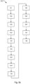
- Fig. 5a illustrates a flow chart of a method 100 of fault prediction in a packaging machine 300 having independently movable objects 301 configured to manipulate packaging containers.
- the order in which the steps of the method 100 are described and illustrated should not be construed as limiting and it is conceivable that the steps can be performed in varying order.
- the method 100 comprises registering 101 data values associated with the motion of the movable objects along the track, determining 102 a distribution of said data values, calculating 103 a measure of central tendency of the data values in the distribution, calculating 104 a quantified measure of a shape of the distribution, associating 105 the measure of central tendency with said quantified measure of the shape as a coupled set of condition parameters, determining 106 a degree of dispersion of a plurality of coupled sets of condition parameters associated with a plurality of motion cycles of the independently movable objects, and comparing 107 the degree of dispersion with a dispersion threshold value, or determining 108) a trend of the degree of dispersion over time, for said fault prediction.
- the method 100 thus provides for the advantageous benefits as described above in relation to the apparatus 200 with reference to Figs. 1 - 4 .
- the method 100 provides for a facilitated and reliable condition monitoring and fault prediction with indication of increased wear, or generally faulty machine components, without the need for complex frequency analysis of the movement characteristics of the components.
- the sensor 204 may be configured to register the data values as a current supplied to the track for moving the independently movable objects 301 along the track 303. This may provide for an advantageous indicator of malfunction or wear since the current is linked to the force required to overcome the friction of the track 303 and propel the independent movable objects 301 in the desired direction. As the wear increases, the force required to move the objects 301 may increase, as well as the current supplied to the track 301 to move the particular object 301. It may be advantageous to determine the current for a movement on a straight portion of the track 303, where forces such as centrifugal forces are limited, and when the related movable object 301 has a constant velocity. This provides for facilitated isolation of the contribution of the wear of the components.
- the sensor measurements may be performed with an initial determination of a base line of the obtained data values. Subsequent measurements may then be compared to such base line of data values.
- the sensor 204 may be configured to register the data values as vibration data, and/or acceleration data, and/or velocity data of the movement of the independently movable objects along the track 301.
- the sensor 204 may also register other types of data that may characterize the motion of the objects 301.
- the sensor 204 may comprise a microphone that records the sound of the movement or induced by the movement. Increased wear of the moving components may lead to the generation of sound that is characteristic of an impending fault or breakdown.
- the sensor 204 may comprise an infrared sensor, i.e. an infrared camera that is configured to receive image data being indicative of the temperature of the independently movable objects 301. This provides for identification of any overheating movable object 301 which may indicate increased friction and wear.
- the sensor 204 is configured to register the data values as position error values.
- the position error values are associated with a difference between a set position of a selected independently movable object 301 on the track 303 and an actual position of said selected independently movable 301 on the track 303.
- the position error value may for example be the time required to move the selected movable object 301 from the actual position to the set position on the track 303. In case a fault has occurred or wear is increasing, the difference between the actual position and the set position may increase, as well as the time required to compensate movement for such errors.
- the sensor 204 may be configured to receive data values from the track 303.
- the sensor 204 may for example be mounted close to the track 303 to receive vibration data from the track 303 when the objects 301 move.
- the sensor 204 may comprise a plurality of sensor units positioned at various locations around the track 303 to provide such data.
- the processing unit 201 may be configured to register the data values at a defined time interval when a selected independently movable object 301 passes a defined location of the track 303. It is thus possible to track the behavior of a specific independently movable object 301.
- the senor 204 may be attached to the independently movable objects 301. This is schematically indicated in Fig. 1 by a secondary sensor unit 204' attached to one of the movable objects 301.
- the secondary sensor unit 204' may send data as it moves along with the movable object 301 on the track 303, and send data comprising any of the above mentioned characteristics, such as acceleration of the movable object 301.
- the sensor 204' may be powered by energy supplied to the track 303 or by an onboard power supply such as a battery. It is also conceivable that the sensor 204' may be powered by an energy harvesting system that generates energy from e.g. the vibration of the independently movable object 301 over a time period. For example, power may be accumulated with onboard capacitors, and thereafter utilized to transmit the data at defined intervals to a static receiver.
- the data recorded by the sensor 204 attached to a specific movable object 301 may also be used as a signature or fingerprint of the movement at a specific point in time, which later can be compared to subsequent data collected for that specific movable object 301, in order to foresee a possible degraded health status.
- additional sensor units may be mounted to other parts of the machine 300 to register motion characteristics of such parts that may influence the data retrieved from the independent movable objects 301.
- the data registered from the independently movable objects 301 may thus be isolated by subtracting the contribution from the other moving parts, hence improving the signal to noise ratio.
- Fig. 5b illustrates a further flow chart of a method 100 of fault prediction of a cyclically moving machine component.
- the order in which the steps of the method 100 are described and illustrated should not be construed as limiting and it is conceivable that the steps can be performed in varying order.
- the data values may be registered at a defined time interval when a selected independently movable object 301 passes a defined location of the track 303. Hence, it is possible to isolate the contribution from a specific movable object 301.
- the control unit 302 may thus be configured to send data to the sensor 204 and/or the processing unit 204 to synchronize the position of a specific movable object 301 to the currently recorded sensor data.
- the data values may comprise vibration data, and/or acceleration data, and/or velocity data of the independently movable objects 301, and/or a current supplied to the track 303 for moving the independently movable objects 301 along the track 303.
- Calculating a measure of central tendency the data values in the distribution may comprise calculating 103' a mean value, such as an arithmetic mean, and/or a geometric mean such as a quadratic mean (RMS), and/or a harmonic mean, and/or a generalized mean, and/or other measures of a central tendency of the distribution such as a median value or a mode value, and/or differently weighted and/or truncated variants thereof.
- the method 100 may be optimized to various applications depending on the particular measure of central tendency employed. An efficient condition monitoring and fault prediction can thereby be achieved for a range of applications and movement characteristics.
- Calculating a quantified measure of a shape of said distribution may comprise calculating 104' a measure of a distribution of the data values around the measure of central tendency.
- the shape of the distribution around the measure of central tendency is determined, which subsequently is associated with the latter for providing the set of coupled condition parameters for the particular motion cycle.
- Calculating a measure of a distribution of the measured data values around said measure of central tendency may comprise calculating 104" a measure of a deviation from a standard normal distribution. This will provide a measure of how the shape of the distribution is different from a standard normal distribution, e.g. if the tails of the distribution are thicker - i.e. more concentrated towards the measure of central tendency - or thinner tails - i.e. in a more even "low-profiled" distribution with a greater spread around the measure of central tendency.
- the shape of the distribution can thus be considered as a measure that describes the shape of the distribution's tails in relation to its overall shape.
- Calculating a quantified measure of a shape of the distribution may comprise calculating 104''' a kurtosis value of the distribution.
- kurtosis is such a measure of the shape of the distribution.
- the first category of kurtosis is a mesokurtic distribution. This type of kurtosis is the most similar to a standard normal distribution in that it also resembles a bell curve. However, a graph that is mesokurtic has fatter tails than a standard normal distribution and has a slightly lower peak.
- This type of kurtosis is considered normally distributed but is not a standard normal distribution.
- the second category is a leptokurtic distribution. Any distribution that is leptokurtic displays greater kurtosis than a mesokurtic distribution. Characteristics of this type of distribution is one with thicker tails and a substantially thin and tall peak. The other type of distribution is a platykurtic distribution. These types of distributions have slender tails and a peak that's smaller than a mesokurtic distribution. Other measures of the shape of the distribution may be determined, such as the skewness describing asymmetry from the normal distribution in a set of data. The method 100 may be thus optimized to various applications depending on the particular measure of the shape of the distribution employed.
- Determining 106 a degree of dispersion of the plurality of coupled sets of condition parameters may comprise determining 106' a fraction of the plurality of coupled sets of condition parameters being contained within a set threshold dispersion.
- the threshold dispersion may be illustrated as a circle, having a particular radius (R), in which a predetermined amount of the coupled sets of condition parameters (i.e. the data points in Figs. 4a-b ) should be contained.
- R particular radius
- a predetermined amount of the coupled sets of condition parameters i.e. the data points in Figs. 4a-b
- 100% of the data points are contained within the respective circles at times t 1 and t 2 , since the radius has been increased at t 2 to accommodate the increased degree of dispersion.
- the fraction of data points contained within the radius will decrease.
- An acceptable range in the fraction of the data points to be contained within the defined radius may thus be set.
- a fixed fraction of data points to be contained may be defined, where the respective radiuses fall
- Determining a degree of dispersion of the plurality of coupled sets of condition parameters may comprise determining 106" the distances 202, 202', between a center 203 of a distribution of the plurality of coupled sets of condition parameters and each coupled set of condition parameters.
- Fig. 4b schematically illustrates how the distances 202, 202', to two different data points, i.e. coupled sets of condition parameters, have been determined with respect to a determined center 203 of the distribution.
- the distance may thus be an Euclidian distance between the aforementioned points. It is conceivable however that other measures of the dispersion of the data points may be utilized.
- the degree of dispersion may be determined by calculating the spread of the interquartile range (IQR, IQR') of the coupled sets of condition parameters. E.g. an increase in the interquartile range, i.e. a spread in the range of radiuses in which 25-75% of the data points are contained may be shown. Thus, as the dispersion increases the interquartile range IQR' is increased, providing for an efficient measure of the dispersion of the coupled sets of condition parameters.
- a computer program product comprising instructions which, when the program is executed by a computer, cause the computer to carry out the steps of the method 100 as described above in relation to Figs. 1 - 5 .
- the processing unit 201 may be configured to calculate the measure of central tendency of the data values in the distribution by calculating 103' a mean value, such as an arithmetic mean, and/or a geometric mean, and/or a harmonic mean, and/or a generalized mean such as a quadratic mean (RMS), and/or other measures of a central tendency of the distribution such as a median value or a mode value, and/or differently weighted and/or truncated variants thereof.
- a mean value such as an arithmetic mean, and/or a geometric mean, and/or a harmonic mean
- a generalized mean such as a quadratic mean (RMS)
- RMS quadratic mean
- the processing unit 201 may be configured to calculate a quantified measure of a shape of said distribution by calculating 104′′′ a kurtosis value of the data distribution.
- the processing unit 201 may be configured to determine the degree of dispersion of the plurality of coupled sets of condition parameters by calculating 106' a fraction of the plurality of coupled sets of condition parameters being contained within a set threshold dispersion.
Landscapes
- Engineering & Computer Science (AREA)
- Mechanical Engineering (AREA)
- Physics & Mathematics (AREA)
- General Physics & Mathematics (AREA)
- Testing Of Devices, Machine Parts, Or Other Structures Thereof (AREA)
- Measurement Of Mechanical Vibrations Or Ultrasonic Waves (AREA)
Description
- The present invention generally relates to the field of condition monitoring. More particularly, the present invention relates to a method of fault prediction in a packaging machine having independently moving objects, and an apparatus for predicting fault in such packaging machine or related systems for producing sealed packages.
- Condition monitoring of machine components in production lines, such as in the manufacturing of sealed packages in filling- and packaging machines or related systems, is critical for ensuring a desired functionality over a period of time and fault prediction. Monitoring distortions in the movements of machine components is an essential part in achieving the desired functionality control and prevent wear-related breakdown. Distortion analysis of e.g. vibrations in bearings is an important part of industrial predictive maintenance programs so that wear and damages can be discovered and repaired before the machine breaks down, thus reducing operating and maintenance costs. More recently conveyor systems based on linear motor technology is used for manipulating packaging containers in the manufacturing of sealed packages. These conveyor systems typically comprise a closed loop track, and a plurality of movable objects or carts, which are independently moved along the track by individually controlling a plurality of solenoids along the track. The independently movable objects or carts are controlled to engage the packaging containers in various operations. Systems based on such independently movable objects pose new challenges in the field of condition monitoring and fault prediction. Empirical evaluation of vibration levels is an error-prone activity that may lead to significantly underestimate or overestimate the remaining lifetime of the components. Previous solutions to characterize bearing faults include frequency analysis, where characteristic frequency signatures are extracted from a vibration signal. Besides from being complex to implement, solutions based on frequency analysis are not always accurate and makes various assumptions with regards to the model used for the calculations, which makes fault prediction sub-optimal for the aforementioned systems utilizing independently movable objects. In particular, it is typically assumed that the motor to which the bearing is attached to rotates at a constant speed. The assumption of constant rotation speed of the servomotors is severe limitation in the field of automatic machines, in particular for objects or carts moving on a track with independent and variable speed profiles. Methods are employed to accommodate for variable speeds, but such solutions can also be complex to implement and also associated with other limitations and undesirable assumptions
EP 3 373 211 A1 discloses a fault prediction method in a packaging machine, wherein features quantities of measured data associated with the motion of machine components, such as the mean, standard deviation, skewness and steepness, are calculated and compared with feature quantities previously acquired during a learning operation mode. - Hence, an improved condition monitoring would be advantageous and in particular allowing for avoiding more of the above-mentioned problems and compromises, including providing a less complex method of fault prediction, having short execution time and thereby enabling analysis on-the-fly, thereby allowing for a less time-consuming and robust trouble-shooting of independently movable objects.
- Accordingly, examples of the present invention preferably seek to mitigate, alleviate or eliminate one or more deficiencies, disadvantages or issues in the art, such as the above-identified, singly or in any combination by providing a method and a system according to the appended patent claims.
- According to a first aspect a method of fault prediction in a packaging machine is provided. The packaging machine having independently movable objects configured to manipulate packaging containers, the independently movable objects communicating with a control unit configured to control the positions of the independently movable objects along a track. The method comprises registering data values associated with the motion of the movable objects along the track with a sensor, said data values including position error values associated with a difference between a set position of a selected independently movable object on said track and an actual position of said individually movable object, determining a distribution of said data values, calculating a measure of central tendency of the data values in the distribution, calculating a quantified measure of a shape of the distribution, associating the measure of central tendency with said quantified measure of the shape as a coupled set of condition parameters, determining a degree of dispersion of a plurality of coupled sets of condition parameters associated with a plurality of motion cycles of the independently movable objects, and comparing the degree of dispersion with a dispersion threshold value, or determining a trend of the degree of dispersion over time, for said fault prediction.
- According to a second aspect a system comprising a packaging machine and an apparatus configured to predict fault in the packaging machine is provided. The packaging machine having independently movable objects configured to manipulate packaging containers. The independently movable objects communicating with a control unit configured to control the positions of the independently movable objects along a track. The apparatus comprises a sensor configured to register data values associated with the motion of the movable objects along the track, wherein the sensor is configured to register the data values as position error values associate with a difference between a set position of a selected independently movable object on the track and an actual position of the independently movable object on the track, and a processing unit configured to determine a distribution of said data values, calculate a measure of central tendency of the data values in the distribution, calculate a quantified measure of a shape of the distribution, associate the measure of central tendency with said quantified measure as a coupled set of condition parameters, determine a degree of dispersion of a plurality of coupled sets of condition parameters associated with a plurality of motion cycles of the independently movable objects, and compare the degree of dispersion with a dispersion threshold value, or determine a trend of the degree of dispersion over time, for said fault prediction.
- According to a third aspect a computer program product comprising instructions which, when the program is executed by a computer, cause the computer to carry out the steps of the method according to the first aspect.
- Further examples of the invention are defined in the dependent claims, wherein features for the second and third aspects of the disclosure are as for the first aspect mutatis mutandis.
- Some examples of the disclosure provide for an improved method for predicting fault in machine components such as objects being independently movable on a track in packaging machine.
- Some examples of the disclosure provide for facilitated prediction of the life-time of a machine component.
- Some examples of the disclosure provide for a more predictable and efficient maintenance schedule of a machine component.
- Some examples of the disclosure provide for a method of fault prediction, having short execution time and thereby enabling analysis on-the-fly.
- Some examples of the disclosure provide for less time-consuming trouble-shooting of a machine component.
- Some examples of the disclosure provide for improved condition monitoring in a machine such in a filling machine, having a plurality of independently movable objects.
- It should be emphasized that the term "comprises/comprising" when used in this specification is taken to specify the presence of stated features, integers, steps or components but does not preclude the presence or addition of one or more other features, integers, steps, components or groups thereof.
- These and other aspects, features and advantages of which examples of the invention are capable of will be apparent and elucidated from the following description of examples of the present invention, reference being made to the accompanying drawings, in which;
-
Fig. 1 is a schematic illustration of an apparatus configured to predict fault in a packaging machine having independently movable objects moving along a track, -
Figs. 2a-d are diagrams illustrating data values associated with the motion of the movable objects along a track, registered by a sensor attached to the track and/or the moveable objects, including a position (2a), a velocity (2b), a position error (2c), and a current supplied to the track (2d), -
Fig. 3 is a diagram illustrating a distribution of data values associated with the motion of the movable objects along a track; -
Fig. 4a is a diagram of coupled sets of condition parameters, where each set, i.e. data point, is determined as a measure of a central tendency of a distribution of the data values inFig. 1 versus a quantified measure of a shape of such distribution, for two different times; -
Fig. 4b is a magnified view of the coupled sets of condition parameters inFig. 4a at time t2; -
Fig. 5a is a flowchart of a method of fault prediction in a packaging machine, and; -
Fig. 5b is a flowchart of a method of fault prediction in a packaging machine. - Specific examples of the invention will now be described with reference to the accompanying drawings. This invention may, however, be embodied in many different forms and should not be construed as limited to the examples set forth herein; rather, these examples are provided so that this disclosure will be thorough and complete, and will fully convey the scope of the invention to those skilled in the art. The terminology used in the detailed description of the examples illustrated in the accompanying drawings is not intended to be limiting of the invention. In the drawings, like numbers refer to like elements.
-
Fig. 1 is a schematic illustration of anapparatus 200 configured to predict fault in apackaging machine 300 having independentlymovable objects 301 configured to manipulate packaging containers (not shown). The independentlymovable objects 301 communicate with acontrol unit 302 configured to control the positions of the independentlymovable objects 301 along atrack 303. Thetrack 303 may be an endless loop as exemplified inFig. 1 . Although thetrack 303 is shown as an elliptic track, it is conceivable that thetrack 303 may have varying shapes, i.e. extending along a variety of curves with different radiuses of curvatures.Fig. 5a illustrates a flow chart of arelated method 100 of fault prediction in a packaging machine. The order in which the steps of themethod 100 are described and illustrated should not be construed as limiting and it is conceivable that the steps can be performed in varying order. - Turning again to
Fig. 1 , theapparatus 200 comprises asensor 204 configured to register 101 data values associated with the motion of themovable objects 301 along thetrack 303.Figs. 2a-c show examples of such data values versus time, i.e. a position of the independentlymovable objects 301 on the track (2a), a velocity of the independently movable objects 301 (2b), a position error of the independently movable objects 301 (2c), and a current supplied to the track (2d). It is conceivable that the data values may comprise various other measurable characteristics of the motion of the independentlymovable objects 301, which can be registered by thesensor 204 for the purposes of carrying out themethod 100, such as values of torque or any other force, vibration data, or acceleration associated with the movement. Theapparatus 200 comprises aprocessing unit 201 configured to determine 102 a distribution of the data values and to calculate 103 a measure of central tendency of the data values in the distribution.Fig. 3 shows an example of a distribution of data values, in this case amplitude of a movement such as a vibrational movement as function of time. The measure of central tendency should be construed according to the normal meaning of the term within statistical theory, i.e. as a central or typical value for a probability distribution, e.g. for the distribution illustrated in the example ofFig. 3 . Theprocessing unit 201 is configured to calculate 104 a quantified measure of a shape of the determined distribution. Also, the shape of the distribution should be construed according to the normal meaning of the term within statistical theory, i.e. describing the shape of the curvature of the distribution inFig. 3 , such as the characteristics of the tails of such distribution, e.g. how wide or thin the tails of the distribution are, which is influenced by the number of outliers of the data points, i.e. the number of data points being far removed from the main distribution around the center of the distribution. Theprocessing unit 201 is configured to associate 105 the measure of central tendency with the aforementioned quantified measure as a coupled set of condition parameters. I.e. for each motion cycle, a set of condition parameters is determined, where each set is a pair of data points comprising the measure of central tendency and the quantified measure of the shape of the distribution.Figs. 4a-b are schematic diagrams where each data point (small circles with solid lines) correspond to a coupled set of condition parameters. The quantified measure of the shape of the distribution is given on the vertical axis (K), and the measure of central tendency is given on the horizontal axis (M). Theprocessing unit 201 is configured to determine 106 a degree of dispersion of a plurality of coupled sets of condition parameters associated with a plurality of motion cycles of the independently movable objects. The dispersion is indicative of how far each of the coupled sets of condition parameters are removed from eachother. In the example ofFig. 4a , the plurality of coupled sets of condition parameters have been determined for two points in time, t1 and t2. At time t2 the degree of dispersion is larger than at time t1. Theprocessing unit 201 is configured to compare 107 the degree of dispersion with a dispersion threshold value, or determine 108 a trend of the degree of dispersion over time, for the fault prediction. An exceeded threshold value can thus be indicative of increased wear of the independentlymovable object 301. Alternatively, a trend of the degree of dispersion over time can be determined 108, for said fault prediction. For example, a trend of increased dispersion, going from t1 to t2, can be indicative of increased wear of the independentlymovable object 301. - Thus, by associating 105 the measure of central tendency with the quantified measure of the shape as a coupled set of condition parameters, and determining the degree of dispersion thereof for a plurality of motion cycles, a facilitated and reliable indication of increased wear, or a generally faulty independent
movable object 301, can be obtained. E.g. complex frequency analysis of the movement characteristics of the component is not necessary. The various assumptions made in such traditional frequency analysis are thus not needed, and the method of fault prediction described in the present disclosure can be employed to achieve a reliable condition monitoring in a wide variety of applications. Theapparatus 200 andrelated method 100 provides for a method of fault prediction having short execution time and thereby enabling analysis on-the-fly and generally a less time-consuming trouble-shooting of the independentlymovable objects 301, and also for other machine components such as bearings, belts, motors and related components thereof. Such improved fault prediction may be particularly advantageous in filling machines, and related components thereof, in highspeed production lines where condition monitoring is critical for maintaining a high throughput. -
Fig. 5a illustrates a flow chart of amethod 100 of fault prediction in apackaging machine 300 having independentlymovable objects 301 configured to manipulate packaging containers. The order in which the steps of themethod 100 are described and illustrated should not be construed as limiting and it is conceivable that the steps can be performed in varying order. Themethod 100 comprises registering 101 data values associated with the motion of the movable objects along the track, determining 102 a distribution of said data values, calculating 103 a measure of central tendency of the data values in the distribution, calculating 104 a quantified measure of a shape of the distribution, associating 105 the measure of central tendency with said quantified measure of the shape as a coupled set of condition parameters, determining 106 a degree of dispersion of a plurality of coupled sets of condition parameters associated with a plurality of motion cycles of the independently movable objects, and comparing 107 the degree of dispersion with a dispersion threshold value, or determining 108) a trend of the degree of dispersion over time, for said fault prediction. - The
method 100 thus provides for the advantageous benefits as described above in relation to theapparatus 200 with reference toFigs. 1 - 4 . I.e. themethod 100 provides for a facilitated and reliable condition monitoring and fault prediction with indication of increased wear, or generally faulty machine components, without the need for complex frequency analysis of the movement characteristics of the components. - The
sensor 204 may be configured to register the data values as a current supplied to the track for moving the independentlymovable objects 301 along thetrack 303. This may provide for an advantageous indicator of malfunction or wear since the current is linked to the force required to overcome the friction of thetrack 303 and propel the independentmovable objects 301 in the desired direction. As the wear increases, the force required to move theobjects 301 may increase, as well as the current supplied to thetrack 301 to move theparticular object 301. It may be advantageous to determine the current for a movement on a straight portion of thetrack 303, where forces such as centrifugal forces are limited, and when the relatedmovable object 301 has a constant velocity. This provides for facilitated isolation of the contribution of the wear of the components. The sensor measurements may be performed with an initial determination of a base line of the obtained data values. Subsequent measurements may then be compared to such base line of data values. - As mentioned above in relation to
Figs. 2a-d , thesensor 204 may be configured to register the data values as vibration data, and/or acceleration data, and/or velocity data of the movement of the independently movable objects along thetrack 301. Thesensor 204 may also register other types of data that may characterize the motion of theobjects 301. E.g. thesensor 204 may comprise a microphone that records the sound of the movement or induced by the movement. Increased wear of the moving components may lead to the generation of sound that is characteristic of an impending fault or breakdown. Thesensor 204 may comprise an infrared sensor, i.e. an infrared camera that is configured to receive image data being indicative of the temperature of the independentlymovable objects 301. This provides for identification of any overheatingmovable object 301 which may indicate increased friction and wear. - Further, the
sensor 204 is configured to register the data values as position error values. The position error values are associated with a difference between a set position of a selected independentlymovable object 301 on thetrack 303 and an actual position of said selected independently movable 301 on thetrack 303. The position error value may for example be the time required to move the selectedmovable object 301 from the actual position to the set position on thetrack 303. In case a fault has occurred or wear is increasing, the difference between the actual position and the set position may increase, as well as the time required to compensate movement for such errors. - The
sensor 204 may be configured to receive data values from thetrack 303. Thesensor 204 may for example be mounted close to thetrack 303 to receive vibration data from thetrack 303 when theobjects 301 move. Thesensor 204 may comprise a plurality of sensor units positioned at various locations around thetrack 303 to provide such data. As mentioned further below, theprocessing unit 201 may be configured to register the data values at a defined time interval when a selected independentlymovable object 301 passes a defined location of thetrack 303. It is thus possible to track the behavior of a specific independentlymovable object 301. - Alternatively, or in addition, the
sensor 204 may be attached to the independentlymovable objects 301. This is schematically indicated inFig. 1 by a secondary sensor unit 204' attached to one of themovable objects 301. The secondary sensor unit 204' may send data as it moves along with themovable object 301 on thetrack 303, and send data comprising any of the above mentioned characteristics, such as acceleration of themovable object 301. The sensor 204' may be powered by energy supplied to thetrack 303 or by an onboard power supply such as a battery. It is also conceivable that the sensor 204' may be powered by an energy harvesting system that generates energy from e.g. the vibration of the independentlymovable object 301 over a time period. For example, power may be accumulated with onboard capacitors, and thereafter utilized to transmit the data at defined intervals to a static receiver. - The data recorded by the
sensor 204 attached to a specificmovable object 301 may also be used as a signature or fingerprint of the movement at a specific point in time, which later can be compared to subsequent data collected for that specificmovable object 301, in order to foresee a possible degraded health status. - It is also conceivable that additional sensor units may be mounted to other parts of the
machine 300 to register motion characteristics of such parts that may influence the data retrieved from the independentmovable objects 301. The data registered from the independentlymovable objects 301 may thus be isolated by subtracting the contribution from the other moving parts, hence improving the signal to noise ratio. -
Fig. 5b illustrates a further flow chart of amethod 100 of fault prediction of a cyclically moving machine component. The order in which the steps of themethod 100 are described and illustrated should not be construed as limiting and it is conceivable that the steps can be performed in varying order. - The data values may be registered at a defined time interval when a selected independently
movable object 301 passes a defined location of thetrack 303. Hence, it is possible to isolate the contribution from a specificmovable object 301. Thecontrol unit 302 may thus be configured to send data to thesensor 204 and/or theprocessing unit 204 to synchronize the position of a specificmovable object 301 to the currently recorded sensor data. - As mentioned above, the data values may comprise vibration data, and/or acceleration data, and/or velocity data of the independently
movable objects 301, and/or a current supplied to thetrack 303 for moving the independentlymovable objects 301 along thetrack 303. - Calculating a measure of central tendency the data values in the distribution may comprise calculating 103' a mean value, such as an arithmetic mean, and/or a geometric mean such as a quadratic mean (RMS), and/or a harmonic mean, and/or a generalized mean, and/or other measures of a central tendency of the distribution such as a median value or a mode value, and/or differently weighted and/or truncated variants thereof. The
method 100 may be optimized to various applications depending on the particular measure of central tendency employed. An efficient condition monitoring and fault prediction can thereby be achieved for a range of applications and movement characteristics. - Calculating a quantified measure of a shape of said distribution may comprise calculating 104' a measure of a distribution of the data values around the measure of central tendency. Thus, the shape of the distribution around the measure of central tendency is determined, which subsequently is associated with the latter for providing the set of coupled condition parameters for the particular motion cycle.
- Calculating a measure of a distribution of the measured data values around said measure of central tendency may comprise calculating 104" a measure of a deviation from a standard normal distribution. This will provide a measure of how the shape of the distribution is different from a standard normal distribution, e.g. if the tails of the distribution are thicker - i.e. more concentrated towards the measure of central tendency - or thinner tails - i.e. in a more even "low-profiled" distribution with a greater spread around the measure of central tendency. The shape of the distribution can thus be considered as a measure that describes the shape of the distribution's tails in relation to its overall shape.
- Calculating a quantified measure of a shape of the distribution may comprise calculating 104''' a kurtosis value of the distribution. Thus, kurtosis is such a measure of the shape of the distribution. There are typically three categories of kurtosis that can be displayed by a set of data. All measures of kurtosis can be compared against a standard normal distribution, or bell curve. The first category of kurtosis is a mesokurtic distribution. This type of kurtosis is the most similar to a standard normal distribution in that it also resembles a bell curve. However, a graph that is mesokurtic has fatter tails than a standard normal distribution and has a slightly lower peak. This type of kurtosis is considered normally distributed but is not a standard normal distribution. The second category is a leptokurtic distribution. Any distribution that is leptokurtic displays greater kurtosis than a mesokurtic distribution. Characteristics of this type of distribution is one with thicker tails and a substantially thin and tall peak. The other type of distribution is a platykurtic distribution. These types of distributions have slender tails and a peak that's smaller than a mesokurtic distribution. Other measures of the shape of the distribution may be determined, such as the skewness describing asymmetry from the normal distribution in a set of data. The
method 100 may be thus optimized to various applications depending on the particular measure of the shape of the distribution employed. - Determining 106 a degree of dispersion of the plurality of coupled sets of condition parameters may comprise determining 106' a fraction of the plurality of coupled sets of condition parameters being contained within a set threshold dispersion. The threshold dispersion may be illustrated as a circle, having a particular radius (R), in which a predetermined amount of the coupled sets of condition parameters (i.e. the data points in
Figs. 4a-b ) should be contained. In the example ofFig. 4a , 100% of the data points are contained within the respective circles at times t1 and t2, since the radius has been increased at t2 to accommodate the increased degree of dispersion. If the radius is kept fixed, however, over time, the fraction of data points contained within the radius will decrease. An acceptable range in the fraction of the data points to be contained within the defined radius may thus be set. Alternatively, a fixed fraction of data points to be contained may be defined, where the respective radiuses fall within a range. - Determining a degree of dispersion of the plurality of coupled sets of condition parameters may comprise determining 106" the
distances 202, 202', between acenter 203 of a distribution of the plurality of coupled sets of condition parameters and each coupled set of condition parameters.Fig. 4b schematically illustrates how thedistances 202, 202', to two different data points, i.e. coupled sets of condition parameters, have been determined with respect to adetermined center 203 of the distribution. The distance may thus be an Euclidian distance between the aforementioned points. It is conceivable however that other measures of the dispersion of the data points may be utilized. - The degree of dispersion may be determined by calculating the spread of the interquartile range (IQR, IQR') of the coupled sets of condition parameters. E.g. an increase in the interquartile range, i.e. a spread in the range of radiuses in which 25-75% of the data points are contained may be shown. Thus, as the dispersion increases the interquartile range IQR' is increased, providing for an efficient measure of the dispersion of the coupled sets of condition parameters.
- A computer program product is provided comprising instructions which, when the program is executed by a computer, cause the computer to carry out the steps of the
method 100 as described above in relation toFigs. 1 - 5 . - The
processing unit 201 may be configured to calculate the measure of central tendency of the data values in the distribution by calculating 103' a mean value, such as an arithmetic mean, and/or a geometric mean, and/or a harmonic mean, and/or a generalized mean such as a quadratic mean (RMS), and/or other measures of a central tendency of the distribution such as a median value or a mode value, and/or differently weighted and/or truncated variants thereof. - The
processing unit 201 may be configured to calculate a quantified measure of a shape of said distribution by calculating 104‴ a kurtosis value of the data distribution. - The
processing unit 201 may be configured to determine the degree of dispersion of the plurality of coupled sets of condition parameters by calculating 106' a fraction of the plurality of coupled sets of condition parameters being contained within a set threshold dispersion. - The present invention has been described above with reference to specific examples. However, other examples than the above described are equally possible within the scope of the invention. The different features and steps of the invention may be combined in other combinations than those described. The scope of the invention is only limited by the appended patent claims.
- More generally, those skilled in the art will readily appreciate that all parameters, dimensions, materials, and configurations described herein are meant to be exemplary and that the actual parameters, dimensions, materials, and/or configurations will depend upon the specific application or applications for which the teachings of the present invention is/are used.
Claims (12)
- A method (100) of fault prediction in a packaging machine (300) comprising independently movable objects (301) configured to manipulate packaging containers, the independently movable objects communicating with a control unit (302) configured to control the positions of the independently movable objects along a track (303), the method comprising;registering (101) data values associated with the motion of the movable objects along the track with a sensor (204),said data values including position error values associated with a difference between a set position of a selected independently movable object on said track and an actual position of said individually movable object,determining (102) a distribution of said data values,calculating (103) a measure of central tendency of the data values in the distribution,calculating (104) a quantified measure of a shape of the distribution,associating (105) the measure of central tendency with said quantified measure of the shape as a coupled set of condition parameters,determining (106) a degree of dispersion of a plurality of coupled sets of condition parameters associated with a plurality of motion cycles of the independently movable objects, andcomparing (107) the degree of dispersion with a dispersion threshold value, or determining (108) a trend of the degree of dispersion over time, for said fault prediction.
- Method according to claim 1, wherein calculating a measure of central tendency of the data values in the distribution comprises
calculating (103') a mean value, such as an arithmetic mean, and/or a geometric mean, and/or a harmonic mean, and/or a generalized mean, and/or other measures of a central tendency of the distribution such as a median value or a mode value. - Method according to claim 1 or 2, wherein calculating a quantified measure of a shape of said distribution comprises calculating (104') a measure of a distribution of the data values around said measure of central tendency.
- Method according to claim 3, wherein calculating a measure of a distribution of the measured data values around said measure of central tendency comprises calculating (104") a measure of a deviation from a standard normal distribution.
- Method according to any of claims 1 - 4, wherein calculating a quantified measure of a shape of said distribution comprises calculating (104‴) a kurtosis value of said distribution.
- Method according to any of claims 1 - 5, wherein the data values are registered at a defined time interval when a selected independently movable object passes a defined location of the track.
- Method according to any of claims 1 - 6, wherein determining a degree of dispersion of the plurality of coupled sets of condition parameters comprises determining (106") the distances (202, 202') between a center (203) of a distribution of the plurality of coupled sets of condition parameters and each coupled set of condition parameters.
- A system comprising a packaging machine (300) and an apparatus (200) configured to predict fault in the packaging machine (300), the packaging machine comprising independently movable objects configured to manipulate packaging containers and a control unit (302) configured to control the positions of the independently movable objects along a track (303), the independently movable objects communicating with the control unit (302), the apparatus comprisinga sensor (204) configured to register (101) data values associated with the motion of the movable objects along the track, wherein said sensor is configured to register said data values as position error values associated with a difference between a set position of a selected independently movable object on the track and an actual position of said independently movable object on the track,a processing unit (201) configured to:- determine (102) a distribution of said data values, calculate (103) a measure of central tendency of the data values in the distribution,calculate (104) a quantified measure of a shape of the distribution,associate (105) the measure of central tendency with said quantified measure as a coupled set of condition parameters,determine (106) a degree of dispersion of a plurality of coupled sets of condition parameters associated with a plurality of motion cycles of the independently movable objects, andcompare (107) the degree of dispersion with a dispersion threshold value, or determine (108) a trend of the degree of dispersion over time, for said fault prediction.
- System according to any of claim 8, wherein the sensor is configured to receive data values from the track and/or be attached to the independently movable objects.
- System according to any of claims 8 - 9, wherein said processing unit is configured to calculate the measure of central tendency of the data values in the distribution by calculating (103') a mean value, such as an arithmetic mean, and/or a geometric mean, and/or a harmonic mean, and/or a generalized mean, and/or other measures of a central tendency of the distribution such as a median value or a mode value.
- System according to any of claims 8 - 10, wherein said processing unit is configured to calculate a quantified measure of a shape of said distribution by calculating (104-) a kurtosis value of said distribution.
- A computer program product comprising instructions which, when the program is executed by a computer, cause the computer to carry out the steps of the method according to any of claims 1-7.
Applications Claiming Priority (1)
| Application Number | Priority Date | Filing Date | Title |
|---|---|---|---|
| EP18197031 | 2018-09-27 |
Publications (3)
| Publication Number | Publication Date |
|---|---|
| EP3628605A1 EP3628605A1 (en) | 2020-04-01 |
| EP3628605B1 EP3628605B1 (en) | 2021-06-16 |
| EP3628605B2 true EP3628605B2 (en) | 2024-10-30 |
Family
ID=63794300
Family Applications (1)
| Application Number | Title | Priority Date | Filing Date |
|---|---|---|---|
| EP19198553.0A Active EP3628605B2 (en) | 2018-09-27 | 2019-09-20 | Method of fault prediction in a packaging machine |
Country Status (5)
| Country | Link |
|---|---|
| US (1) | US11807464B2 (en) |
| EP (1) | EP3628605B2 (en) |
| JP (1) | JP7398443B2 (en) |
| CN (1) | CN112689600B (en) |
| WO (1) | WO2020064533A1 (en) |
Families Citing this family (10)
| Publication number | Priority date | Publication date | Assignee | Title |
|---|---|---|---|---|
| IT201900017447A1 (en) * | 2019-09-27 | 2021-03-27 | Ocm S P A | TRANSPORT SYSTEM AND HOW IT WORKS |
| US12431736B2 (en) | 2020-05-26 | 2025-09-30 | Tetra Laval Holdings & Finance S.A. | Self-powered sensor unit for food packaging machine |
| US20220413470A1 (en) * | 2021-06-24 | 2022-12-29 | Anritsu Corporation | Production management system and non-transitory storage medium storing production management program |
| WO2023011878A1 (en) * | 2021-08-05 | 2023-02-09 | Tetra Laval Holdings & Finance S.A. | A method of monitoring the condition of a movable member in a linear motor system, corresponding linear motor system, forming assembly and computer program product |
| US11982585B2 (en) * | 2021-09-23 | 2024-05-14 | Rockwell Automation Technologies, Inc. | System and method for strain and acceleration based analytics in an independent cart system |
| CN115266142B (en) * | 2022-07-29 | 2025-09-23 | 广域铭岛数字科技有限公司 | A testing method for electric vehicle |
| DE102022126566A1 (en) * | 2022-10-12 | 2024-04-18 | Bayerische Motoren Werke Aktiengesellschaft | Method for operating a conveyor system and conveyor system |
| US20250145374A1 (en) * | 2023-11-05 | 2025-05-08 | Rockwell Automation Technologies, Inc. | System and Method to Monitor and Balance Wear in an Independent Cart System |
| DE102023132004A1 (en) * | 2023-11-16 | 2025-05-22 | Deutsche Post Ag | Method and means for monitoring a conveyor device |
| EP4575689A1 (en) * | 2023-12-18 | 2025-06-25 | Tetra Laval Holdings & Finance S.A. | A system for monitoring a cyclically moving component of a machine in a food packaging line |
Citations (6)
| Publication number | Priority date | Publication date | Assignee | Title |
|---|---|---|---|---|
| US6392584B1 (en) † | 2000-01-04 | 2002-05-21 | Richard Eklund | System and method for detecting and warning of potential failure of rotating and vibrating machines |
| US20030230941A1 (en) † | 2002-06-05 | 2003-12-18 | Keith Jacobs | Controlled motion system |
| US7026732B1 (en) † | 1998-02-26 | 2006-04-11 | Anorad Corporation | Path arrangement for a multi-track linear motor system and method to control same |
| WO2007008940A2 (en) † | 2005-07-11 | 2007-01-18 | Brooks Automation, Inc. | Intelligent condition-monitoring and dault diagnostic system |
| US20070282545A1 (en) † | 2006-05-17 | 2007-12-06 | Curtiss-Wright Flow Control Corporation | Probabilistic Stress Wave Analysis System and Method |
| US20170088298A1 (en) † | 2015-09-25 | 2017-03-30 | Multi-Pack Solutions, LLC | Packaging machine with independently controllable movers |
Family Cites Families (6)
| Publication number | Priority date | Publication date | Assignee | Title |
|---|---|---|---|---|
| US6370957B1 (en) | 1999-12-31 | 2002-04-16 | Square D Company | Vibration analysis for predictive maintenance of rotating machines |
| US7698942B2 (en) * | 2006-05-12 | 2010-04-20 | Curtiss-Wright Flow Control Corporation | Turbine engine stall warning system |
| GB2496040B (en) * | 2011-10-24 | 2019-04-03 | Fisher Rosemount Systems Inc | Predicted fault analysis |
| CN102789529B (en) * | 2012-07-16 | 2015-05-06 | 华为技术有限公司 | Fault prediction method, device, system and equipment |
| JP6880843B2 (en) | 2017-03-09 | 2021-06-02 | オムロン株式会社 | Management equipment and management program |
| CN107797537A (en) * | 2017-11-10 | 2018-03-13 | 上海第二工业大学 | A kind of prognostic and health management method applied to automatic production line |
-
2019
- 2019-09-20 CN CN201980060051.4A patent/CN112689600B/en active Active
- 2019-09-20 JP JP2021517237A patent/JP7398443B2/en active Active
- 2019-09-20 US US17/280,815 patent/US11807464B2/en active Active
- 2019-09-20 WO PCT/EP2019/075296 patent/WO2020064533A1/en not_active Ceased
- 2019-09-20 EP EP19198553.0A patent/EP3628605B2/en active Active
Patent Citations (6)
| Publication number | Priority date | Publication date | Assignee | Title |
|---|---|---|---|---|
| US7026732B1 (en) † | 1998-02-26 | 2006-04-11 | Anorad Corporation | Path arrangement for a multi-track linear motor system and method to control same |
| US6392584B1 (en) † | 2000-01-04 | 2002-05-21 | Richard Eklund | System and method for detecting and warning of potential failure of rotating and vibrating machines |
| US20030230941A1 (en) † | 2002-06-05 | 2003-12-18 | Keith Jacobs | Controlled motion system |
| WO2007008940A2 (en) † | 2005-07-11 | 2007-01-18 | Brooks Automation, Inc. | Intelligent condition-monitoring and dault diagnostic system |
| US20070282545A1 (en) † | 2006-05-17 | 2007-12-06 | Curtiss-Wright Flow Control Corporation | Probabilistic Stress Wave Analysis System and Method |
| US20170088298A1 (en) † | 2015-09-25 | 2017-03-30 | Multi-Pack Solutions, LLC | Packaging machine with independently controllable movers |
Non-Patent Citations (6)
| Title |
|---|
| CAMERINI V., COPPOTELLI G., BENDISCH S.: "Health Monitoring of Helicopter Drive Train Components Based on Support Vector Data Description", 42ND EUROPEAN ROTORCRAFT FORUM, 1 January 2016 (2016-01-01), [retrieved on 20220330] † |
| JUN OGATA, MURAKAWA MASAHIRO: "Vibration-Based Anomaly Detection Using FLAC Features for Wind Turbine Condition Monitoring", 8TH EUROPEAN WORKSHOP ON STRUCTURAL HEALTH MONITORING (EWSHM 2016), 5-8 JULY 2016, SPAIN, BILBAO, 5 July 2016 (2016-07-05), pages 1 - 10, Retrieved from the Internet <URL:https://www.ndt.net/events/EWSHM2016/app/content/Paper/271_Ogata.pdf> [retrieved on 20180925] † |
| MIKA RUUSUNEN ET AL., QUALITY MONITORING AND FAULT DETECTION IN AN AUTOMATED MANUFACTURING SYSTEM - A SOFT COMPUTING APPROACH, 1 May 2002 (2002-05-01), Retrieved from the Internet <URL:http://jultika.oulu.fi/files/isbn9514275128.pdf> † |
| ONO YUMI; ONISHI YOSHIFUMI; KOSHINAKA TAKAFUMI; TAKATA SOICHIRO; HOSHUYAMA OSAMU: "Anomaly detection of motors with feature emphasis using only normal sounds", ICASSP, IEEE INTERNATIONAL CONFERENCE ON ACOUSTICS, SPEECH AND SIGNAL PROCESSING - PROCEEDINGS 1999 IEEE, IEEE, 26 May 2013 (2013-05-26), pages 2800 - 2804, ISSN: 1520-6149, ISBN: 978-0-7803-5041-0, DOI: 10.1109/ICASSP.2013.6638167 † |
| PURARJOMANDLANGRUDI AFROOZ, AMIR HOSSEIN GHAPANCHI, MOHAMMAD ESMALIFALAK: "A data mining approach for fault diagnosis: An application of anomaly detection algorithm", MEASUREMENT, vol. 55, 11 June 2014 (2014-06-11), pages 343 - 352 † |
| ROEMER M.J., KACPRZYNSKI G.J.: "Advanced diagnostics and prognostics for gas turbine engine risk assessment", AEROSPACE CONFERENCE PROCEEDINGS, 2000 IEEE MARCH 18-25, 2000, PISCATAWAY, NJ, USA,IEEE, vol. 6, 18 March 2000 (2000-03-18) - 25 March 2000 (2000-03-25), pages 345 - 353, ISBN: 978-0-7803-5846-1 † |
Also Published As
| Publication number | Publication date |
|---|---|
| US20210403246A1 (en) | 2021-12-30 |
| JP7398443B2 (en) | 2023-12-14 |
| WO2020064533A1 (en) | 2020-04-02 |
| CN112689600A (en) | 2021-04-20 |
| US11807464B2 (en) | 2023-11-07 |
| EP3628605B1 (en) | 2021-06-16 |
| JP2022502645A (en) | 2022-01-11 |
| CN112689600B (en) | 2022-06-21 |
| EP3628605A1 (en) | 2020-04-01 |
Similar Documents
| Publication | Publication Date | Title |
|---|---|---|
| EP3628605B2 (en) | Method of fault prediction in a packaging machine | |
| EP3415891B1 (en) | Method of fault prediction of a cyclically moving machine component | |
| CN107272586B (en) | Machine learning device, machine learning method, failure prediction device, and failure prediction system | |
| US11614728B2 (en) | Machine tool management system that obtains a next maintenance period from a maintenance period model and a refinement algorithm | |
| US11314241B2 (en) | Abnormality diagnosis apparatus and abnormality diagnosis method | |
| US20220269259A1 (en) | Predictive maintenance for a device in the food industry by means of a digital twin, and optimized production planning | |
| CN108829933A (en) | A kind of method of the predictive maintenance and health control of semiconductor manufacturing facility | |
| KR20150024873A (en) | Methods and apparatus to use vibration data to determine a condition of a process control device | |
| CN113646718B (en) | Abnormality detection device and abnormality detection method | |
| TWI669606B (en) | Diagnostic method for machine and diagnostic system thereof | |
| US20240009905A1 (en) | State determination device and state determination method | |
| CN118393902A (en) | Textile equipment self-adaptive control method and system | |
| CN106489234B (en) | Methods of Monitoring Collision | |
| CN109581087A (en) | Machine tool guideway method for testing performance and system | |
| EP3660613B1 (en) | A method for condition monitoring of a cyclically moving machine component | |
| US20230367293A1 (en) | State determination device and state determination method | |
| WO2023026416A1 (en) | State determination device and state determination method | |
| JP2023530858A (en) | Method for predictive maintenance of automatic machinery for manufacturing or packaging consumer products | |
| JP7184997B2 (en) | State determination device and state determination method | |
| US20220406163A1 (en) | Method for determining and/or verifying a status of a door system, method for generating a model, status determination device, system, computer program product | |
| Çalışkan et al. | Machine Learning-Based Failure Detection Using Internet of Things: A Case Study for Proactive Maintenance | |
| AU2022204043A1 (en) | Method for determining and/or verifying a status of a door system, status determination device, system, computer program product |
Legal Events
| Date | Code | Title | Description |
|---|---|---|---|
| PUAI | Public reference made under article 153(3) epc to a published international application that has entered the european phase |
Free format text: ORIGINAL CODE: 0009012 |
|
| STAA | Information on the status of an ep patent application or granted ep patent |
Free format text: STATUS: THE APPLICATION HAS BEEN PUBLISHED |
|
| AK | Designated contracting states |
Kind code of ref document: A1 Designated state(s): AL AT BE BG CH CY CZ DE DK EE ES FI FR GB GR HR HU IE IS IT LI LT LU LV MC MK MT NL NO PL PT RO RS SE SI SK SM TR |
|
| AX | Request for extension of the european patent |
Extension state: BA ME |
|
| STAA | Information on the status of an ep patent application or granted ep patent |
Free format text: STATUS: REQUEST FOR EXAMINATION WAS MADE |
|
| 17P | Request for examination filed |
Effective date: 20201001 |
|
| RBV | Designated contracting states (corrected) |
Designated state(s): AL AT BE BG CH CY CZ DE DK EE ES FI FR GB GR HR HU IE IS IT LI LT LU LV MC MK MT NL NO PL PT RO RS SE SI SK SM TR |
|
| GRAP | Despatch of communication of intention to grant a patent |
Free format text: ORIGINAL CODE: EPIDOSNIGR1 |
|
| STAA | Information on the status of an ep patent application or granted ep patent |
Free format text: STATUS: GRANT OF PATENT IS INTENDED |
|
| RIC1 | Information provided on ipc code assigned before grant |
Ipc: B65B 57/02 20060101ALI20201029BHEP Ipc: B65B 57/00 20060101AFI20201029BHEP Ipc: B65G 54/02 20060101ALI20201029BHEP Ipc: G05B 23/02 20060101ALN20201029BHEP Ipc: B65G 43/04 20060101ALI20201029BHEP |
|
| INTG | Intention to grant announced |
Effective date: 20201117 |
|
| RIN1 | Information on inventor provided before grant (corrected) |
Inventor name: COCCONCELLI, MARCO Inventor name: CAPELLI, LUCA Inventor name: CAVALAGLIO CAMARGO MOLANO, JACOPO Inventor name: BORGHI, DAVIDE |
|
| GRAJ | Information related to disapproval of communication of intention to grant by the applicant or resumption of examination proceedings by the epo deleted |
Free format text: ORIGINAL CODE: EPIDOSDIGR1 |
|
| STAA | Information on the status of an ep patent application or granted ep patent |
Free format text: STATUS: REQUEST FOR EXAMINATION WAS MADE |
|
| GRAP | Despatch of communication of intention to grant a patent |
Free format text: ORIGINAL CODE: EPIDOSNIGR1 |
|
| STAA | Information on the status of an ep patent application or granted ep patent |
Free format text: STATUS: GRANT OF PATENT IS INTENDED |
|
| INTC | Intention to grant announced (deleted) | ||
| RIC1 | Information provided on ipc code assigned before grant |
Ipc: G05B 23/02 20060101ALN20210303BHEP Ipc: B65G 43/04 20060101ALI20210303BHEP Ipc: B65B 57/02 20060101ALI20210303BHEP Ipc: B65B 57/00 20060101AFI20210303BHEP Ipc: B65G 54/02 20060101ALI20210303BHEP |
|
| RIC1 | Information provided on ipc code assigned before grant |
Ipc: B65B 57/00 20060101AFI20210310BHEP Ipc: B65B 57/02 20060101ALI20210310BHEP Ipc: B65G 43/04 20060101ALI20210310BHEP Ipc: B65G 54/02 20060101ALI20210310BHEP Ipc: G05B 23/02 20060101ALN20210310BHEP |
|
| INTG | Intention to grant announced |
Effective date: 20210324 |
|
| GRAS | Grant fee paid |
Free format text: ORIGINAL CODE: EPIDOSNIGR3 |
|
| GRAA | (expected) grant |
Free format text: ORIGINAL CODE: 0009210 |
|
| STAA | Information on the status of an ep patent application or granted ep patent |
Free format text: STATUS: THE PATENT HAS BEEN GRANTED |
|
| AK | Designated contracting states |
Kind code of ref document: B1 Designated state(s): AL AT BE BG CH CY CZ DE DK EE ES FI FR GB GR HR HU IE IS IT LI LT LU LV MC MK MT NL NO PL PT RO RS SE SI SK SM TR |
|
| REG | Reference to a national code |
Ref country code: GB Ref legal event code: FG4D |
|
| REG | Reference to a national code |
Ref country code: CH Ref legal event code: EP |
|
| REG | Reference to a national code |
Ref country code: DE Ref legal event code: R096 Ref document number: 602019005381 Country of ref document: DE |
|
| REG | Reference to a national code |
Ref country code: AT Ref legal event code: REF Ref document number: 1402162 Country of ref document: AT Kind code of ref document: T Effective date: 20210715 |
|
| REG | Reference to a national code |
Ref country code: IE Ref legal event code: FG4D |
|
| REG | Reference to a national code |
Ref country code: LT Ref legal event code: MG9D |
|
| PG25 | Lapsed in a contracting state [announced via postgrant information from national office to epo] |
Ref country code: HR Free format text: LAPSE BECAUSE OF FAILURE TO SUBMIT A TRANSLATION OF THE DESCRIPTION OR TO PAY THE FEE WITHIN THE PRESCRIBED TIME-LIMIT Effective date: 20210616 Ref country code: LT Free format text: LAPSE BECAUSE OF FAILURE TO SUBMIT A TRANSLATION OF THE DESCRIPTION OR TO PAY THE FEE WITHIN THE PRESCRIBED TIME-LIMIT Effective date: 20210616 Ref country code: FI Free format text: LAPSE BECAUSE OF FAILURE TO SUBMIT A TRANSLATION OF THE DESCRIPTION OR TO PAY THE FEE WITHIN THE PRESCRIBED TIME-LIMIT Effective date: 20210616 Ref country code: BG Free format text: LAPSE BECAUSE OF FAILURE TO SUBMIT A TRANSLATION OF THE DESCRIPTION OR TO PAY THE FEE WITHIN THE PRESCRIBED TIME-LIMIT Effective date: 20210916 |
|
| REG | Reference to a national code |
Ref country code: AT Ref legal event code: MK05 Ref document number: 1402162 Country of ref document: AT Kind code of ref document: T Effective date: 20210616 |
|
| REG | Reference to a national code |
Ref country code: NL Ref legal event code: MP Effective date: 20210616 |
|
| PG25 | Lapsed in a contracting state [announced via postgrant information from national office to epo] |
Ref country code: NO Free format text: LAPSE BECAUSE OF FAILURE TO SUBMIT A TRANSLATION OF THE DESCRIPTION OR TO PAY THE FEE WITHIN THE PRESCRIBED TIME-LIMIT Effective date: 20210916 Ref country code: LV Free format text: LAPSE BECAUSE OF FAILURE TO SUBMIT A TRANSLATION OF THE DESCRIPTION OR TO PAY THE FEE WITHIN THE PRESCRIBED TIME-LIMIT Effective date: 20210616 Ref country code: RS Free format text: LAPSE BECAUSE OF FAILURE TO SUBMIT A TRANSLATION OF THE DESCRIPTION OR TO PAY THE FEE WITHIN THE PRESCRIBED TIME-LIMIT Effective date: 20210616 Ref country code: SE Free format text: LAPSE BECAUSE OF FAILURE TO SUBMIT A TRANSLATION OF THE DESCRIPTION OR TO PAY THE FEE WITHIN THE PRESCRIBED TIME-LIMIT Effective date: 20210616 Ref country code: GR Free format text: LAPSE BECAUSE OF FAILURE TO SUBMIT A TRANSLATION OF THE DESCRIPTION OR TO PAY THE FEE WITHIN THE PRESCRIBED TIME-LIMIT Effective date: 20210917 |
|
| PG25 | Lapsed in a contracting state [announced via postgrant information from national office to epo] |
Ref country code: EE Free format text: LAPSE BECAUSE OF FAILURE TO SUBMIT A TRANSLATION OF THE DESCRIPTION OR TO PAY THE FEE WITHIN THE PRESCRIBED TIME-LIMIT Effective date: 20210616 Ref country code: ES Free format text: LAPSE BECAUSE OF FAILURE TO SUBMIT A TRANSLATION OF THE DESCRIPTION OR TO PAY THE FEE WITHIN THE PRESCRIBED TIME-LIMIT Effective date: 20210616 Ref country code: SK Free format text: LAPSE BECAUSE OF FAILURE TO SUBMIT A TRANSLATION OF THE DESCRIPTION OR TO PAY THE FEE WITHIN THE PRESCRIBED TIME-LIMIT Effective date: 20210616 Ref country code: CZ Free format text: LAPSE BECAUSE OF FAILURE TO SUBMIT A TRANSLATION OF THE DESCRIPTION OR TO PAY THE FEE WITHIN THE PRESCRIBED TIME-LIMIT Effective date: 20210616 Ref country code: AT Free format text: LAPSE BECAUSE OF FAILURE TO SUBMIT A TRANSLATION OF THE DESCRIPTION OR TO PAY THE FEE WITHIN THE PRESCRIBED TIME-LIMIT Effective date: 20210616 Ref country code: SM Free format text: LAPSE BECAUSE OF FAILURE TO SUBMIT A TRANSLATION OF THE DESCRIPTION OR TO PAY THE FEE WITHIN THE PRESCRIBED TIME-LIMIT Effective date: 20210616 Ref country code: NL Free format text: LAPSE BECAUSE OF FAILURE TO SUBMIT A TRANSLATION OF THE DESCRIPTION OR TO PAY THE FEE WITHIN THE PRESCRIBED TIME-LIMIT Effective date: 20210616 Ref country code: PT Free format text: LAPSE BECAUSE OF FAILURE TO SUBMIT A TRANSLATION OF THE DESCRIPTION OR TO PAY THE FEE WITHIN THE PRESCRIBED TIME-LIMIT Effective date: 20211018 Ref country code: RO Free format text: LAPSE BECAUSE OF FAILURE TO SUBMIT A TRANSLATION OF THE DESCRIPTION OR TO PAY THE FEE WITHIN THE PRESCRIBED TIME-LIMIT Effective date: 20210616 |
|
| PG25 | Lapsed in a contracting state [announced via postgrant information from national office to epo] |
Ref country code: PL Free format text: LAPSE BECAUSE OF FAILURE TO SUBMIT A TRANSLATION OF THE DESCRIPTION OR TO PAY THE FEE WITHIN THE PRESCRIBED TIME-LIMIT Effective date: 20210616 |
|
| REG | Reference to a national code |
Ref country code: DE Ref legal event code: R026 Ref document number: 602019005381 Country of ref document: DE |
|
| PLBI | Opposition filed |
Free format text: ORIGINAL CODE: 0009260 |
|
| PLAX | Notice of opposition and request to file observation + time limit sent |
Free format text: ORIGINAL CODE: EPIDOSNOBS2 |
|
| 26 | Opposition filed |
Opponent name: KRONES AG Effective date: 20220316 |
|
| PG25 | Lapsed in a contracting state [announced via postgrant information from national office to epo] |
Ref country code: DK Free format text: LAPSE BECAUSE OF FAILURE TO SUBMIT A TRANSLATION OF THE DESCRIPTION OR TO PAY THE FEE WITHIN THE PRESCRIBED TIME-LIMIT Effective date: 20210616 |
|
| REG | Reference to a national code |
Ref country code: BE Ref legal event code: MM Effective date: 20210930 |
|
| PG25 | Lapsed in a contracting state [announced via postgrant information from national office to epo] |
Ref country code: MC Free format text: LAPSE BECAUSE OF FAILURE TO SUBMIT A TRANSLATION OF THE DESCRIPTION OR TO PAY THE FEE WITHIN THE PRESCRIBED TIME-LIMIT Effective date: 20210616 Ref country code: AL Free format text: LAPSE BECAUSE OF FAILURE TO SUBMIT A TRANSLATION OF THE DESCRIPTION OR TO PAY THE FEE WITHIN THE PRESCRIBED TIME-LIMIT Effective date: 20210616 |
|
| PLAF | Information modified related to communication of a notice of opposition and request to file observations + time limit |
Free format text: ORIGINAL CODE: EPIDOSCOBS2 |
|
| PG25 | Lapsed in a contracting state [announced via postgrant information from national office to epo] |
Ref country code: LU Free format text: LAPSE BECAUSE OF NON-PAYMENT OF DUE FEES Effective date: 20210920 Ref country code: IE Free format text: LAPSE BECAUSE OF NON-PAYMENT OF DUE FEES Effective date: 20210920 Ref country code: FR Free format text: LAPSE BECAUSE OF NON-PAYMENT OF DUE FEES Effective date: 20210930 Ref country code: BE Free format text: LAPSE BECAUSE OF NON-PAYMENT OF DUE FEES Effective date: 20210930 |
|
| PLBB | Reply of patent proprietor to notice(s) of opposition received |
Free format text: ORIGINAL CODE: EPIDOSNOBS3 |
|
| REG | Reference to a national code |
Ref country code: CH Ref legal event code: PL |
|
| P01 | Opt-out of the competence of the unified patent court (upc) registered |
Effective date: 20230426 |
|
| PG25 | Lapsed in a contracting state [announced via postgrant information from national office to epo] |
Ref country code: CY Free format text: LAPSE BECAUSE OF FAILURE TO SUBMIT A TRANSLATION OF THE DESCRIPTION OR TO PAY THE FEE WITHIN THE PRESCRIBED TIME-LIMIT Effective date: 20210616 |
|
| PG25 | Lapsed in a contracting state [announced via postgrant information from national office to epo] |
Ref country code: LI Free format text: LAPSE BECAUSE OF NON-PAYMENT OF DUE FEES Effective date: 20220930 Ref country code: HU Free format text: LAPSE BECAUSE OF FAILURE TO SUBMIT A TRANSLATION OF THE DESCRIPTION OR TO PAY THE FEE WITHIN THE PRESCRIBED TIME-LIMIT; INVALID AB INITIO Effective date: 20190920 Ref country code: CH Free format text: LAPSE BECAUSE OF NON-PAYMENT OF DUE FEES Effective date: 20220930 |
|
| PG25 | Lapsed in a contracting state [announced via postgrant information from national office to epo] |
Ref country code: MK Free format text: LAPSE BECAUSE OF FAILURE TO SUBMIT A TRANSLATION OF THE DESCRIPTION OR TO PAY THE FEE WITHIN THE PRESCRIBED TIME-LIMIT Effective date: 20210616 |
|
| APBP | Date of receipt of notice of appeal recorded |
Free format text: ORIGINAL CODE: EPIDOSNNOA2O |
|
| APAH | Appeal reference modified |
Free format text: ORIGINAL CODE: EPIDOSCREFNO |
|
| GBPC | Gb: european patent ceased through non-payment of renewal fee |
Effective date: 20230920 |
|
| PG25 | Lapsed in a contracting state [announced via postgrant information from national office to epo] |
Ref country code: GB Free format text: LAPSE BECAUSE OF NON-PAYMENT OF DUE FEES Effective date: 20230920 |
|
| APBU | Appeal procedure closed |
Free format text: ORIGINAL CODE: EPIDOSNNOA9O |
|
| PG25 | Lapsed in a contracting state [announced via postgrant information from national office to epo] |
Ref country code: GB Free format text: LAPSE BECAUSE OF NON-PAYMENT OF DUE FEES Effective date: 20230920 |
|
| PUAH | Patent maintained in amended form |
Free format text: ORIGINAL CODE: 0009272 |
|
| STAA | Information on the status of an ep patent application or granted ep patent |
Free format text: STATUS: PATENT MAINTAINED AS AMENDED |
|
| PG25 | Lapsed in a contracting state [announced via postgrant information from national office to epo] |
Ref country code: MT Free format text: LAPSE BECAUSE OF FAILURE TO SUBMIT A TRANSLATION OF THE DESCRIPTION OR TO PAY THE FEE WITHIN THE PRESCRIBED TIME-LIMIT Effective date: 20210616 |
|
| 27A | Patent maintained in amended form |
Effective date: 20241030 |
|
| AK | Designated contracting states |
Kind code of ref document: B2 Designated state(s): AL AT BE BG CH CY CZ DE DK EE ES FI FR GB GR HR HU IE IS IT LI LT LU LV MC MK MT NL NO PL PT RO RS SE SI SK SM TR |
|
| REG | Reference to a national code |
Ref country code: DE Ref legal event code: R102 Ref document number: 602019005381 Country of ref document: DE |
|
| PGFP | Annual fee paid to national office [announced via postgrant information from national office to epo] |
Ref country code: DE Payment date: 20250926 Year of fee payment: 7 |
|
| PGFP | Annual fee paid to national office [announced via postgrant information from national office to epo] |
Ref country code: IT Payment date: 20250922 Year of fee payment: 7 |
|
| PG25 | Lapsed in a contracting state [announced via postgrant information from national office to epo] |
Ref country code: TR Free format text: LAPSE BECAUSE OF FAILURE TO SUBMIT A TRANSLATION OF THE DESCRIPTION OR TO PAY THE FEE WITHIN THE PRESCRIBED TIME-LIMIT Effective date: 20210616 |