EP3628591A1 - Flow guide body with fluidic actuator for an aircraft - Google Patents
Flow guide body with fluidic actuator for an aircraft Download PDFInfo
- Publication number
- EP3628591A1 EP3628591A1 EP19198594.4A EP19198594A EP3628591A1 EP 3628591 A1 EP3628591 A1 EP 3628591A1 EP 19198594 A EP19198594 A EP 19198594A EP 3628591 A1 EP3628591 A1 EP 3628591A1
- Authority
- EP
- European Patent Office
- Prior art keywords
- flow control
- outlet
- control device
- inlet
- flow
- Prior art date
- Legal status (The legal status is an assumption and is not a legal conclusion. Google has not performed a legal analysis and makes no representation as to the accuracy of the status listed.)
- Withdrawn
Links
- 230000003993 interaction Effects 0.000 claims abstract description 45
- 239000003381 stabilizer Substances 0.000 claims description 8
- 238000007664 blowing Methods 0.000 description 10
- 238000000926 separation method Methods 0.000 description 6
- 238000010586 diagram Methods 0.000 description 1
- 230000010349 pulsation Effects 0.000 description 1
Images

Classifications
-
- F—MECHANICAL ENGINEERING; LIGHTING; HEATING; WEAPONS; BLASTING
- F15—FLUID-PRESSURE ACTUATORS; HYDRAULICS OR PNEUMATICS IN GENERAL
- F15D—FLUID DYNAMICS, i.e. METHODS OR MEANS FOR INFLUENCING THE FLOW OF GASES OR LIQUIDS
- F15D1/00—Influencing flow of fluids
- F15D1/002—Influencing flow of fluids by influencing the boundary layer
- F15D1/0065—Influencing flow of fluids by influencing the boundary layer using active means, e.g. supplying external energy or injecting fluid
- F15D1/008—Influencing flow of fluids by influencing the boundary layer using active means, e.g. supplying external energy or injecting fluid comprising fluid injection or suction means
-
- B—PERFORMING OPERATIONS; TRANSPORTING
- B64—AIRCRAFT; AVIATION; COSMONAUTICS
- B64C—AEROPLANES; HELICOPTERS
- B64C3/00—Wings
- B64C3/58—Wings provided with fences or spoilers
-
- B—PERFORMING OPERATIONS; TRANSPORTING
- B64—AIRCRAFT; AVIATION; COSMONAUTICS
- B64C—AEROPLANES; HELICOPTERS
- B64C21/00—Influencing air flow over aircraft surfaces by affecting boundary layer flow
- B64C21/02—Influencing air flow over aircraft surfaces by affecting boundary layer flow by use of slot, ducts, porous areas or the like
- B64C21/04—Influencing air flow over aircraft surfaces by affecting boundary layer flow by use of slot, ducts, porous areas or the like for blowing
-
- B—PERFORMING OPERATIONS; TRANSPORTING
- B64—AIRCRAFT; AVIATION; COSMONAUTICS
- B64C—AEROPLANES; HELICOPTERS
- B64C21/00—Influencing air flow over aircraft surfaces by affecting boundary layer flow
- B64C21/02—Influencing air flow over aircraft surfaces by affecting boundary layer flow by use of slot, ducts, porous areas or the like
- B64C21/08—Influencing air flow over aircraft surfaces by affecting boundary layer flow by use of slot, ducts, porous areas or the like adjustable
-
- B—PERFORMING OPERATIONS; TRANSPORTING
- B64—AIRCRAFT; AVIATION; COSMONAUTICS
- B64C—AEROPLANES; HELICOPTERS
- B64C23/00—Influencing air flow over aircraft surfaces, not otherwise provided for
- B64C23/06—Influencing air flow over aircraft surfaces, not otherwise provided for by generating vortices
- B64C23/065—Influencing air flow over aircraft surfaces, not otherwise provided for by generating vortices at the wing tips
- B64C23/069—Influencing air flow over aircraft surfaces, not otherwise provided for by generating vortices at the wing tips using one or more wing tip airfoil devices, e.g. winglets, splines, wing tip fences or raked wingtips
-
- B—PERFORMING OPERATIONS; TRANSPORTING
- B64—AIRCRAFT; AVIATION; COSMONAUTICS
- B64C—AEROPLANES; HELICOPTERS
- B64C9/00—Adjustable control surfaces or members, e.g. rudders
-
- F—MECHANICAL ENGINEERING; LIGHTING; HEATING; WEAPONS; BLASTING
- F15—FLUID-PRESSURE ACTUATORS; HYDRAULICS OR PNEUMATICS IN GENERAL
- F15B—SYSTEMS ACTING BY MEANS OF FLUIDS IN GENERAL; FLUID-PRESSURE ACTUATORS, e.g. SERVOMOTORS; DETAILS OF FLUID-PRESSURE SYSTEMS, NOT OTHERWISE PROVIDED FOR
- F15B21/00—Common features of fluid actuator systems; Fluid-pressure actuator systems or details thereof, not covered by any other group of this subclass
- F15B21/12—Fluid oscillators or pulse generators
-
- F—MECHANICAL ENGINEERING; LIGHTING; HEATING; WEAPONS; BLASTING
- F15—FLUID-PRESSURE ACTUATORS; HYDRAULICS OR PNEUMATICS IN GENERAL
- F15D—FLUID DYNAMICS, i.e. METHODS OR MEANS FOR INFLUENCING THE FLOW OF GASES OR LIQUIDS
- F15D1/00—Influencing flow of fluids
- F15D1/08—Influencing flow of fluids of jets leaving an orifice
-
- F—MECHANICAL ENGINEERING; LIGHTING; HEATING; WEAPONS; BLASTING
- F15—FLUID-PRESSURE ACTUATORS; HYDRAULICS OR PNEUMATICS IN GENERAL
- F15D—FLUID DYNAMICS, i.e. METHODS OR MEANS FOR INFLUENCING THE FLOW OF GASES OR LIQUIDS
- F15D1/00—Influencing flow of fluids
- F15D1/14—Diverting flow into alternative channels
-
- B—PERFORMING OPERATIONS; TRANSPORTING
- B64—AIRCRAFT; AVIATION; COSMONAUTICS
- B64C—AEROPLANES; HELICOPTERS
- B64C2230/00—Boundary layer controls
- B64C2230/04—Boundary layer controls by actively generating fluid flow
-
- B—PERFORMING OPERATIONS; TRANSPORTING
- B64—AIRCRAFT; AVIATION; COSMONAUTICS
- B64C—AEROPLANES; HELICOPTERS
- B64C2230/00—Boundary layer controls
- B64C2230/06—Boundary layer controls by explicitly adjusting fluid flow, e.g. by using valves, variable aperture or slot areas, variable pump action or variable fluid pressure
-
- B—PERFORMING OPERATIONS; TRANSPORTING
- B64—AIRCRAFT; AVIATION; COSMONAUTICS
- B64C—AEROPLANES; HELICOPTERS
- B64C2230/00—Boundary layer controls
- B64C2230/22—Boundary layer controls by using a surface having multiple apertures of relatively small openings other than slots
-
- F—MECHANICAL ENGINEERING; LIGHTING; HEATING; WEAPONS; BLASTING
- F15—FLUID-PRESSURE ACTUATORS; HYDRAULICS OR PNEUMATICS IN GENERAL
- F15C—FLUID-CIRCUIT ELEMENTS PREDOMINANTLY USED FOR COMPUTING OR CONTROL PURPOSES
- F15C1/00—Circuit elements having no moving parts
- F15C1/08—Boundary-layer devices, e.g. wall-attachment amplifiers coanda effect
- F15C1/10—Boundary-layer devices, e.g. wall-attachment amplifiers coanda effect for digital operation, e.g. to form a logical flip-flop, OR-gate, NOR-gate, AND-gate; Comparators; Pulse generators
- F15C1/12—Multiple arrangements thereof for performing operations of the same kind, e.g. majority gates, identity gates ; Counting circuits; Sliding registers
-
- F—MECHANICAL ENGINEERING; LIGHTING; HEATING; WEAPONS; BLASTING
- F15—FLUID-PRESSURE ACTUATORS; HYDRAULICS OR PNEUMATICS IN GENERAL
- F15C—FLUID-CIRCUIT ELEMENTS PREDOMINANTLY USED FOR COMPUTING OR CONTROL PURPOSES
- F15C1/00—Circuit elements having no moving parts
- F15C1/22—Oscillators
-
- Y—GENERAL TAGGING OF NEW TECHNOLOGICAL DEVELOPMENTS; GENERAL TAGGING OF CROSS-SECTIONAL TECHNOLOGIES SPANNING OVER SEVERAL SECTIONS OF THE IPC; TECHNICAL SUBJECTS COVERED BY FORMER USPC CROSS-REFERENCE ART COLLECTIONS [XRACs] AND DIGESTS
- Y02—TECHNOLOGIES OR APPLICATIONS FOR MITIGATION OR ADAPTATION AGAINST CLIMATE CHANGE
- Y02T—CLIMATE CHANGE MITIGATION TECHNOLOGIES RELATED TO TRANSPORTATION
- Y02T50/00—Aeronautics or air transport
- Y02T50/10—Drag reduction
Definitions
- the present invention relates to a flow guide body for an aircraft, in particular a flow guide body for active flow control by pulsed air jet blowing.
- a further aspect of the invention relates to an aircraft comprising such a flow guide body.
- AFC Active flow control
- VTP vertical tail plane
- HTP horizontal tail plane
- slats, flaps or vortex generators are commonly applied on aerodynamic surfaces where the flow is prone to separation due to high aerodynamic loading or unsteady geometry, such as wing, vertical tail plane (VTP) or horizontal tail plane (HTP), and where other measures, such as slats, flaps or vortex generators, cannot be implemented or are not preferred.
- steady or pulsed blowing actuators are distributed in the aerodynamic surface ejecting jets of air at the same time at different positions to delay of suppress flow separation.
- AFC with steady blowing actuators is applied to control large aerodynamic areas the amount of air required by the flow control device is undesirably high, in particular when the air is drawn from the bleed air system. By using pulsed blowing actuators the amount of required air can be reduced.
- WO 2012/048853 A1 An example of a pulsed blowing actuator AFC system is known from WO 2012/048853 A1 .
- WO 2012/048853 A1 describes an AFC system comprising a flow guide body with a plurality of flow control devices, wherein flow control devices of a first stage are fed by a common air supply line connected to their inlets, while the first and second outlets of a flow control device of a second stage are connected to the first and second control inlets of a flow control device of the first stage, so that the pulsed blowing of the flow control device of the first stage is controlled by the flow control device of the second stage.
- the object of the present invention is to provide a flow guide body for active flow control, wherein a minimum amount of air is required without a significant loss in flow control efficiency.
- a flow guide body for an aircraft wherein the flow guide body comprises a main body and a plurality of air flow control devices.
- the main body has an outer aerodynamic surface that is provided with a plurality of outlet openings.
- the flow control devices are preferably arranged in the main body.
- Each of the plurality of air flow control devices comprises an inlet, an interaction chamber, a first outlet and a second outlet.
- the interaction chamber extends from a first end to a second end along a preferably straight chamber axis.
- the inlet is connected with the interaction chamber at the first end.
- the first outlet is connected with the interaction chamber at the second end such that the first outlet projects towards a first side of the chamber axis.
- the second outlet is connected with the interaction chamber at the second end such that the second outlet projects towards a second side of the chamber axis opposite the first side.
- the interaction chamber is provided with a first control inlet connected to the interaction chamber at the first side of the chamber axis and configured to deflect the flow to exit the interaction chamber at the second outlet.
- At least one first flow control device of the plurality of air flow control devices is arranged such that the first and second outlets of the first flow control device are each connected to an outlet opening in the aerodynamic surface.
- the first outlet of the at least one first flow control device is provided with a first control outlet and the second outlet of the at least one first flow control device is provided with a second control outlet.
- At least one second flow control device of the plurality of air flow control devices is arranged such that the first or second outlet of the at least one second flow control device is connected with the inlet of the at least one first flow control device.
- One of the first and second control outlets of the at least one first flow control device is connected to the first control inlet of the at least one first flow control device.
- the other of the first and second control outlets of the at least one first flow control device is connected to the first or second control inlet, preferably to the first control inlet, of the at least one second flow control device or of a third or further flow control device.
- At least two first flow control devices are provided.
- the first outlet of the at least one second flow control device is connected with the inlet of one of the two first flow control devices.
- the second outlet of the at least one second flow control device is connected with the inlet of the other of the two first flow control devices.
- the first control outlet is connected with the first control inlet.
- the second control outlet of that first flow control device the inlet of which is connected to the first outlet of the at least one second flow control device is connected to the first control inlet of the at least one second flow control device.
- the interaction chamber of the at least one second flow control device is provided with a second control inlet connected to the interaction chamber at the second side of the chamber axis and configured to deflect the flow to exit the interaction chamber at the first outlet.
- the second control outlet of that first flow control device the inlet of which is connected to the second outlet of the at least one second flow control device, is connected to the second control inlet of the at least one second flow control device. In such a way, a two-stage system having four outlets is formed.
- the inlet of the at least one second flow control device is connected to a feed line connected to a supply of compressed air.
- the second stage thus represents the inlet stage that is supplied with compressed air from the feed line.
- At least one third flow control device of the plurality of air flow control devices is arranged such that one of the first and second outlet of the at least one third flow control device is connected with the inlet of the at least one second flow control device.
- the second control outlet of that first flow control device the inlet of which is connected to the second outlet of the at least one second flow control device is connected to the first control inlet of the at least one third flow control device.
- at least two second flow control devices and at least four first flow control devices are provided.
- the first outlet of a second one of the at least two second flow control devices is connected with the inlet of a third one of the four first flow control devices.
- the second outlet the second one of the at least two second flow control devices is connected with the inlet of a fourth one of the four first flow control devices.
- the other of the first or second outlet of the at least one third flow control device is connected with the inlet of the second one of at least one second flow control device.
- the first control outlet is connected with the first control inlet.
- the second control outlet of that first flow control device the inlet of which is connected to the first outlet of the second one of the at least two second flow control devices is connected to the first control inlet of the second one of the at least two second flow control devices.
- the interaction chamber of the at least one third flow control device is provided with a second control inlet connected to the interaction chamber at the second side of the chamber axis and configured to deflect the flow to exit the interaction chamber at the first outlet.
- the second control outlet of that first flow control device the inlet of which is connected to the second outlet of the second one of the at least two second flow control devices, is connected to the second control inlet of the at least one third flow control device.
- a three-stage system having eight outlets is formed. It is understood that a flow guide body comprising four or more stages can be formed accordingly.
- the inlet of the at least one third flow control device is connected to a feed line connected to a supply of compressed air.
- the third second stage represents the inlet stage that is supplied with compressed air from the feed line.
- each of the plurality of flow control devices are configured such that when the inlet is initially supplied with compressed air, an airflow is guided from the inlet to the first outlet.
- the form of the interaction chamber of each of the plurality of flow control devices is preset to the first direction, preferably by an asymmetric course, such that when their respective inlet is initially supplied with compressed air, an airflow is guided from the inlet to the first outlet. In such a way, the wave-formed pulsed blowing out of the outlet openings in the aerodynamic surface is generated.
- the flow control devices might also be preset to the second direction, depending on the intended starting point and direction of movement of the wave.
- connections between the first and second control outlets and the first and second control inlets are formed by feedback channels.
- the feedback channels are preferably provided in the main body and adapted for a direct and minimum drag feedback.
- the flow guide body is formed by a wing section with the outlet openings adjacent to a flap and/or a slat, e.g. along a main wing leading edge and/or along a main wing trailing edge. In such a way, flow separation in the area of a flap or a slat can be prevented.
- the flow guide body is formed by a vertical stabilizer with the outlet openings arranged adjacent to a rudder, e.g. along a rudder hinge line. In such a way, flow separation in the area of a rudder can be prevented.
- the flow guide body is formed by a horizontal stabilizer with the outlet openings arranged adjacent to an elevator, e.g. along an elevator hinge line. In such a way, flow separation in the area of an elevator can be prevented.
- the flow guide body is formed by a wing having winglets at the distal end, wherein the outlet openings are arranged at the leading edge of the winglet. In such a way, flow separation at the winglet can be prevented.
- a further aspect of the present invention relates to an aircraft comprising the flow guide body according to any of the embodiments described herein.
- the features and advantageous described in connection with the flow guide body apply vis-à-vis to the aircraft.
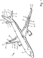
- FIG. 1 an aircraft 1 according to an embodiment of the present invention is shown.
- the aircraft 1 comprises a fuselage 3, wings 5, a horizontal tail plane 7 including a horizontal stabilizer 9 and an elevator 11, and a vertical tail plane 13 including a vertical stabilizer 15 and a rudder 17.
- flow guide bodies 19 are included in the aircraft 1 a) in the form of a wing section 20 with outlet openings 21 adjacent to a flap 23 and a slat 25, b) in the form of the vertical stabilizer 15 with the outlet openings 21 arranged adjacent to a rudder 17, c) in the form of the horizontal stabilizer 9 with the outlet openings 21 arranged adjacent to an elevator 11, and d) in the form of the wing 5 having winglets 27 at the distal end, wherein the outlet openings 21 are arranged at the leading edge of the winglet 27.
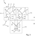
- the flow guide body 19 relates to a two-stage design.
- the flow guide body 19 comprises a main body 29 and a plurality of air flow control devices 31, in the present case three flow control devices 31, two first flow control devices 31a relating to a first stage A and one second flow control device 31b relating to a second stage B.
- the main body 29 has an outer aerodynamic surface 33 that is provided with the plurality of outlet openings 21.
- the flow control devices 31 are arranged in the main body 29.
- Each of the flow control devices 31 comprises an inlet 35, an interaction chamber 37, a first outlet 39 and a second outlet 41.
- the interaction chamber 37 extends from a first end 43 to a second end 45 along a straight chamber axis 47.
- the inlet 35 is connected with the interaction chamber 37 at the first end 43.
- the first outlet 39 is connected with the interaction chamber 37 at the second end 45 such that the first outlet 39 projects towards a first side 49 of the chamber axis 47.
- the second outlet 41 is connected with the interaction chamber 37 at the second end 45 such that the second outlet 41 projects towards a second side 51 of the chamber axis 47 opposite the first side 49.
- the interaction chamber 37 is provided with a first control inlet 53 connected to the interaction chamber 37 at the first side 49 of the chamber axis 47.
- the first flow control devices 31a are arranged such that their first and second outlets 39, 41 are each connected to outlet openings 21 in the aerodynamic surface 33. Additionally, the first outlet 39 of each first flow control device 31a is provided with a first control outlet 55 and the second outlet 41 of each first flow control device 31a is provided with a second control outlet 57.
- the first outlet 39 of the second flow control device 31b is connected with the inlet 35 of one of the two first flow control devices 31a.
- the second outlet 41 of the second flow control device 31b is connected with the inlet 35 of the other of the two first flow control devices 31a.
- the first control outlet 55 is connected with the first control inlet 53.
- the second control outlet 57 of that first flow control device 31a the inlet 35 of which is connected to the first outlet 39 of the second flow control device 31b, is connected to the first control inlet 53 of the second flow control device 31b.
- the interaction chamber 37 of the second flow control device 31b is provided with a second control inlet 59 connected to the interaction chamber 37 at the second side 51 of the chamber axis 47.
- the second control outlet 57 of that first flow control device 31a the inlet 35 of which is connected to the second outlet 41 of the second flow control device 31b, is connected to the second control inlet 59 of the second flow control device 31b.
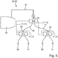
- the inlet 35 of the second flow control device 31b is connected to a feed line 61 connected to a supply 63 of compressed air, in the present case to a bleed air system 65 of an engine 67, as it is shown in Fig. 5 .
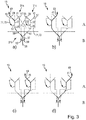
- pulsed blowing in the form of a wave can be generated, as shown in Fig. 3 .
- the wave is formed by four subsequent blowing pulses of air travelling from the first side 49 to the second side 51, in the present illustration from left to right.
- Each of the flow control devices 31 is configured such that when the inlet 35 is initially supplied with compressed air, an airflow 69 is guided from the inlet 35 to the first outlet 39. This is done by the interaction chamber 37 of the flow control devices 31 being formed with a preset asymmetry to urge the airflow 69 to the first side 49 and thus to the first outlet 39.
- the air flow 69 initially exits the flow guide body 19 at the first outlet 39 of the first one of the first flow control devices 31a, see Fig. 3 a) .
- a partial air flow 71 also exits the first control outlet 55 of the first one of the first flow control devices 31a and is passed to the first control inlet 53 of the first one of the first flow control devices 31a via a feedback channel 73.
- the partial air flow 71 through the first control inlet 53 of the first one of the first flow control devices 31a actuates the airflow 69 through the interaction chamber 37 to exit the flow guide body 19 through the second outlet 41 of the first one of the first flow control devices 31a, see Fig. 3 b) .
- a partial air flow 71 Simultaneously to the airflow 69 exiting the second outlet 41 of the first one of the first flow control devices 31a, a partial air flow 71 also exits the second control outlet 57 of the first one of the first flow control devices 31a and is passed to the first control inlet 53 of the second flow control device 31b via a feedback channel 73.
- the partial air flow 71 through the first control inlet 53 of the second flow control device 31b actuates the airflow 69 through the interaction chamber 37 of the second flow control device 31b to exit the second flow control device 31b through its second outlet 41 and enter the inlet 35 of the second one of the first flow control devices 31a, where the airflow 69 exits the flow guide body 19 through the first outlet 39 due to the presetting to the first side 49, see Fig. 3 c) .
- a partial air flow 71 also exits the first control outlet 55 of the second one of the first flow control devices 31a and is passed to the first control inlet 53 of the second one of the first flow control devices 31a via a feedback channel 73.
- the partial air flow 71 through the first control inlet 53 of the second one of the first flow control devices 31a actuates the airflow 69 through the interaction chamber 37 to exit the flow guide body 19 through the second outlet 41 of the second one of the first flow control devices 31a, see Fig. 3 d) .
- a partial air flow 71 Simultaneously to the airflow 69 exiting the second outlet 41 of the second one of the first flow control devices 31a, a partial air flow 71 also exits the second control outlet 57 of the second one of the first flow control devices 31a and is passed to the second control inlet 59 of the second flow control device 31b via a feedback channel 73.
- the partial air flow 71 through the second control inlet 59 of the second flow control device 31b actuates the airflow 69 through the interaction chamber 37 of the second flow control device 31b to switch to its initial path and exit the second flow control device 31b through its first outlet 39 and enter the inlet 35 of the first one of the first flow control devices 31a, so that a new wave begins.
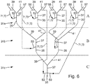
- Fig. 6 shows an embodiment of the flow guide body 19 relating to a three-stage design, comprising six flow control devices 31, four first flow control devices 31a relating to a first stage A, two second flow control devices 31b relating to a second stage A, and one third flow control device 31c relating to a third stage C.
- the three-stage design widely incorporates the two-stage design as described above, so that only the differences of the three stage design with respect to the two-stage design are described hereinafter.
- the third flow control device 31c is arranged such that the first outlet 39 of the third flow control device 31c is connected with the inlet 35 of the first one of the second flow control devices 31b.
- the first outlet 39 of a second one of the two second flow control devices 31b is connected with the inlet 35 of a third one of the four first flow control devices 31a.
- the second outlet 41 of the second one of the two second flow control devices 31b is connected with the inlet 35 of a fourth one of the four first flow control devices 31a.
- the second outlet 41 of the third flow control device 31c is connected with the inlet 35 of the second one of the two second flow control devices 31b.
- the first control outlet 55 is connected with the first control inlet 53.
- the second control outlet 57 of that first flow control device 31a the inlet 35 of which is connected to the first outlet 39 of the second one of the two second flow control devices 31b, is connected to the first control inlet 53 of the second one of the two second flow control devices 31b.
- the interaction chamber 37 of the third flow control device 31c is provided with a second control inlet 59 connected to the interaction chamber 37 at the second side 51 of the chamber axis 47.
- the second control outlet 57 of that first flow control device 31a the inlet 35 of which is connected to the second outlet 41 of the second one of the two second flow control devices 31b, is connected to the second control inlet 59 of the third flow control device 31c.
- the inlet 35 of the third flow control device 31c is connected to a feed line 61 connected to a supply 63 of compressed air, such as an engine bleed air system.
Landscapes
- Engineering & Computer Science (AREA)
- Aviation & Aerospace Engineering (AREA)
- Mechanical Engineering (AREA)
- Physics & Mathematics (AREA)
- Fluid Mechanics (AREA)
- General Engineering & Computer Science (AREA)
- Chemical & Material Sciences (AREA)
- Analytical Chemistry (AREA)
- Multiple-Way Valves (AREA)
- Air-Conditioning For Vehicles (AREA)
- Structures Of Non-Positive Displacement Pumps (AREA)
- Aerodynamic Tests, Hydrodynamic Tests, Wind Tunnels, And Water Tanks (AREA)
Abstract
Disclosed is a flow guide body (19) for an aircraft (1), comprising a main body (29) having an outer aerodynamic surface (33) provided with a plurality of outlet openings (21), and a plurality of flow control devices (31), each flow control device (31) comprising an inlet (35), an interaction chamber (37), a first outlet (39) and a second outlet (41), wherein a first control inlet (53) is connected to the interaction chamber (37) at the first side (49) of the chamber axis (47), wherein the first and second outlets (39, 41) are each connected to outlet openings (21) in the aerodynamic surface (33), wherein the first outlet (39) is provided with a first control outlet (55) and the second outlet (41) is provided with a second control outlet (57), wherein at least one second flow control device (31b) is arranged such that the first or second outlet (39, 41) is connected with the inlet (35) of the first flow control device (31a), wherein one of the first and second control outlets (55, 57) of the first flow control device (31a) is connected to the first control inlet (53) of the first flow control device (31a), and wherein the other of the first and second control outlets (55, 57) of the first flow control device (31a) is connected to the first control inlet (53, 59) of the second flow control device (31b).
Description
- The present invention relates to a flow guide body for an aircraft, in particular a flow guide body for active flow control by pulsed air jet blowing. A further aspect of the invention relates to an aircraft comprising such a flow guide body.
- Active flow control (AFC) is commonly applied on aerodynamic surfaces where the flow is prone to separation due to high aerodynamic loading or unsteady geometry, such as wing, vertical tail plane (VTP) or horizontal tail plane (HTP), and where other measures, such as slats, flaps or vortex generators, cannot be implemented or are not preferred. For AFC, steady or pulsed blowing actuators are distributed in the aerodynamic surface ejecting jets of air at the same time at different positions to delay of suppress flow separation. When AFC with steady blowing actuators is applied to control large aerodynamic areas the amount of air required by the flow control device is undesirably high, in particular when the air is drawn from the bleed air system. By using pulsed blowing actuators the amount of required air can be reduced.
- An example of a pulsed blowing actuator AFC system is known from
WO 2012/048853 A1 .WO 2012/048853 A1 describes an AFC system comprising a flow guide body with a plurality of flow control devices, wherein flow control devices of a first stage are fed by a common air supply line connected to their inlets, while the first and second outlets of a flow control device of a second stage are connected to the first and second control inlets of a flow control device of the first stage, so that the pulsed blowing of the flow control device of the first stage is controlled by the flow control device of the second stage. - The object of the present invention is to provide a flow guide body for active flow control, wherein a minimum amount of air is required without a significant loss in flow control efficiency.
- This object is achieved by a flow guide body for an aircraft, wherein the flow guide body comprises a main body and a plurality of air flow control devices. The main body has an outer aerodynamic surface that is provided with a plurality of outlet openings. The flow control devices are preferably arranged in the main body. Each of the plurality of air flow control devices comprises an inlet, an interaction chamber, a first outlet and a second outlet.
- The interaction chamber extends from a first end to a second end along a preferably straight chamber axis. The inlet is connected with the interaction chamber at the first end. The first outlet is connected with the interaction chamber at the second end such that the first outlet projects towards a first side of the chamber axis. The second outlet is connected with the interaction chamber at the second end such that the second outlet projects towards a second side of the chamber axis opposite the first side. The interaction chamber is provided with a first control inlet connected to the interaction chamber at the first side of the chamber axis and configured to deflect the flow to exit the interaction chamber at the second outlet. At least one first flow control device of the plurality of air flow control devices is arranged such that the first and second outlets of the first flow control device are each connected to an outlet opening in the aerodynamic surface. The first outlet of the at least one first flow control device is provided with a first control outlet and the second outlet of the at least one first flow control device is provided with a second control outlet. At least one second flow control device of the plurality of air flow control devices is arranged such that the first or second outlet of the at least one second flow control device is connected with the inlet of the at least one first flow control device. One of the first and second control outlets of the at least one first flow control device is connected to the first control inlet of the at least one first flow control device. The other of the first and second control outlets of the at least one first flow control device is connected to the first or second control inlet, preferably to the first control inlet, of the at least one second flow control device or of a third or further flow control device. This means, in contrast to the prior art where the control inlets are supplied by the outlets of the subsequent stage, in the present invention the control inlets of all stages are supplied by the control outlets of the first stage.
- By such a flow guide body, a pulsed blowing out of the outlet openings in the aerodynamic surface in the form of a wave is obtained, which relates to a pulsation form that requires only a minimum of air supply while at the same time flow control efficiency is not significantly affected.
- According to a preferred embodiment, at least two first flow control devices are provided. Preferably, the first outlet of the at least one second flow control device is connected with the inlet of one of the two first flow control devices. Preferably, the second outlet of the at least one second flow control device is connected with the inlet of the other of the two first flow control devices. Preferably, in each of the first flow control devices the first control outlet is connected with the first control inlet. Preferably, the second control outlet of that first flow control device the inlet of which is connected to the first outlet of the at least one second flow control device, is connected to the first control inlet of the at least one second flow control device. In such way, a two or more-stage system might be formed.
- In particular, it is preferred that the interaction chamber of the at least one second flow control device is provided with a second control inlet connected to the interaction chamber at the second side of the chamber axis and configured to deflect the flow to exit the interaction chamber at the first outlet. Preferably, the second control outlet of that first flow control device the inlet of which is connected to the second outlet of the at least one second flow control device, is connected to the second control inlet of the at least one second flow control device. In such a way, a two-stage system having four outlets is formed.
- It is further preferred that the inlet of the at least one second flow control device is connected to a feed line connected to a supply of compressed air. The second stage thus represents the inlet stage that is supplied with compressed air from the feed line.
- According to an alternative preferred embodiment, at least one third flow control device of the plurality of air flow control devices is arranged such that one of the first and second outlet of the at least one third flow control device is connected with the inlet of the at least one second flow control device. Preferably, the second control outlet of that first flow control device the inlet of which is connected to the second outlet of the at least one second flow control device, is connected to the first control inlet of the at least one third flow control device. It is further preferred that at least two second flow control devices and at least four first flow control devices are provided. Preferably, the first outlet of a second one of the at least two second flow control devices is connected with the inlet of a third one of the four first flow control devices. Preferably, the second outlet the second one of the at least two second flow control devices is connected with the inlet of a fourth one of the four first flow control devices. Preferably, the other of the first or second outlet of the at least one third flow control device is connected with the inlet of the second one of at least one second flow control device. Preferably, in each of the first flow control devices the first control outlet is connected with the first control inlet. Preferably, the second control outlet of that first flow control device the inlet of which is connected to the first outlet of the second one of the at least two second flow control devices, is connected to the first control inlet of the second one of the at least two second flow control devices. Preferably, the interaction chamber of the at least one third flow control device is provided with a second control inlet connected to the interaction chamber at the second side of the chamber axis and configured to deflect the flow to exit the interaction chamber at the first outlet. Preferably, the second control outlet of that first flow control device the inlet of which is connected to the second outlet of the second one of the at least two second flow control devices, is connected to the second control inlet of the at least one third flow control device. In such a way, a three-stage system having eight outlets is formed. It is understood that a flow guide body comprising four or more stages can be formed accordingly.
- In particular, it is preferred that the inlet of the at least one third flow control device is connected to a feed line connected to a supply of compressed air. In this case, the third second stage represents the inlet stage that is supplied with compressed air from the feed line.
- According to a preferred embodiment, each of the plurality of flow control devices are configured such that when the inlet is initially supplied with compressed air, an airflow is guided from the inlet to the first outlet. In particular, the form of the interaction chamber of each of the plurality of flow control devices is preset to the first direction, preferably by an asymmetric course, such that when their respective inlet is initially supplied with compressed air, an airflow is guided from the inlet to the first outlet. In such a way, the wave-formed pulsed blowing out of the outlet openings in the aerodynamic surface is generated. It is understood that the flow control devices might also be preset to the second direction, depending on the intended starting point and direction of movement of the wave.
- According to another preferred embodiment, the connections between the first and second control outlets and the first and second control inlets are formed by feedback channels. The feedback channels are preferably provided in the main body and adapted for a direct and minimum drag feedback.
- According to another preferred embodiment, the flow guide body is formed by a wing section with the outlet openings adjacent to a flap and/or a slat, e.g. along a main wing leading edge and/or along a main wing trailing edge. In such a way, flow separation in the area of a flap or a slat can be prevented.
- According to an alternative preferred embodiment, the flow guide body is formed by a vertical stabilizer with the outlet openings arranged adjacent to a rudder, e.g. along a rudder hinge line. In such a way, flow separation in the area of a rudder can be prevented.
- According to an alternative preferred embodiment, the flow guide body is formed by a horizontal stabilizer with the outlet openings arranged adjacent to an elevator, e.g. along an elevator hinge line. In such a way, flow separation in the area of an elevator can be prevented.
- According to an alternative preferred embodiment, the flow guide body is formed by a wing having winglets at the distal end, wherein the outlet openings are arranged at the leading edge of the winglet. In such a way, flow separation at the winglet can be prevented.
- A further aspect of the present invention relates to an aircraft comprising the flow guide body according to any of the embodiments described herein. The features and advantageous described in connection with the flow guide body apply vis-à-vis to the aircraft.
- Preferred embodiments of the present invention are described hereinafter in more detail by means of a drawing. The drawing shows in
- Fig. 1
- a perspective view of an aircraft according to the invention,
- Fig. 2
- a schematic illustration of a first embodiment of the flow guide body relating to a two-stage design,
- Fig. 3
- an operation diagram of the flow guide body shown in
Fig. 2 , - Fig. 4
- a cross-sectional view of the flow guide body shown in
Fig. 2 , - Fig. 5
- a schematic view of the flow guide body shown in
Fig. 2 as connected to a feed line of an aircraft bleed air system, and - Fig. 6
- a schematic view of a second embodiment of the flow guide body relating to a three-stage design.
- In
Fig. 1 an aircraft 1 according to an embodiment of the present invention is shown. The aircraft 1 comprises afuselage 3,wings 5, ahorizontal tail plane 7 including ahorizontal stabilizer 9 and anelevator 11, and a vertical tail plane 13 including avertical stabilizer 15 and arudder 17. Several flow guidebodies 19 according to an embodiment of the invention are included in the aircraft 1 a) in the form of a wing section 20 withoutlet openings 21 adjacent to aflap 23 and aslat 25, b) in the form of thevertical stabilizer 15 with theoutlet openings 21 arranged adjacent to arudder 17, c) in the form of thehorizontal stabilizer 9 with theoutlet openings 21 arranged adjacent to anelevator 11, and d) in the form of thewing 5 havingwinglets 27 at the distal end, wherein theoutlet openings 21 are arranged at the leading edge of thewinglet 27. - One of the
flow guide bodies 19 is shown in more detail inFigs. 2 to 5 . Thisflow guide body 19 relates to a two-stage design. Theflow guide body 19 comprises amain body 29 and a plurality of airflow control devices 31, in the present case threeflow control devices 31, two firstflow control devices 31a relating to a first stage A and one secondflow control device 31b relating to a second stage B. Themain body 29 has an outeraerodynamic surface 33 that is provided with the plurality ofoutlet openings 21. Theflow control devices 31 are arranged in themain body 29. Each of theflow control devices 31 comprises aninlet 35, aninteraction chamber 37, afirst outlet 39 and asecond outlet 41. Theinteraction chamber 37 extends from afirst end 43 to asecond end 45 along astraight chamber axis 47. Theinlet 35 is connected with theinteraction chamber 37 at thefirst end 43. Thefirst outlet 39 is connected with theinteraction chamber 37 at thesecond end 45 such that thefirst outlet 39 projects towards afirst side 49 of thechamber axis 47. Thesecond outlet 41 is connected with theinteraction chamber 37 at thesecond end 45 such that thesecond outlet 41 projects towards asecond side 51 of thechamber axis 47 opposite thefirst side 49. Theinteraction chamber 37 is provided with afirst control inlet 53 connected to theinteraction chamber 37 at thefirst side 49 of thechamber axis 47. The firstflow control devices 31a are arranged such that their first andsecond outlets outlet openings 21 in theaerodynamic surface 33. Additionally, thefirst outlet 39 of each firstflow control device 31a is provided with afirst control outlet 55 and thesecond outlet 41 of each firstflow control device 31a is provided with asecond control outlet 57. - As shown in
Figs. 2 and4 , thefirst outlet 39 of the secondflow control device 31b is connected with theinlet 35 of one of the two firstflow control devices 31a. Thesecond outlet 41 of the secondflow control device 31b is connected with theinlet 35 of the other of the two firstflow control devices 31a. In each of the firstflow control devices 31a thefirst control outlet 55 is connected with thefirst control inlet 53. Thesecond control outlet 57 of that firstflow control device 31a theinlet 35 of which is connected to thefirst outlet 39 of the secondflow control device 31b, is connected to thefirst control inlet 53 of the secondflow control device 31b. Theinteraction chamber 37 of the secondflow control device 31b is provided with asecond control inlet 59 connected to theinteraction chamber 37 at thesecond side 51 of thechamber axis 47. Thesecond control outlet 57 of that firstflow control device 31a theinlet 35 of which is connected to thesecond outlet 41 of the secondflow control device 31b, is connected to thesecond control inlet 59 of the secondflow control device 31b. Theinlet 35 of the secondflow control device 31b is connected to afeed line 61 connected to a supply 63 of compressed air, in the present case to a bleed air system 65 of anengine 67, as it is shown inFig. 5 . - By such a two-stage
flow guide body 19, pulsed blowing in the form of a wave can be generated, as shown inFig. 3 . The wave is formed by four subsequent blowing pulses of air travelling from thefirst side 49 to thesecond side 51, in the present illustration from left to right. Each of theflow control devices 31 is configured such that when theinlet 35 is initially supplied with compressed air, anairflow 69 is guided from theinlet 35 to thefirst outlet 39. This is done by theinteraction chamber 37 of theflow control devices 31 being formed with a preset asymmetry to urge theairflow 69 to thefirst side 49 and thus to thefirst outlet 39. - As the flow guide body is initially preset to the
first side 49, theair flow 69 initially exits theflow guide body 19 at thefirst outlet 39 of the first one of the firstflow control devices 31a, seeFig. 3 a) . Simultaneously to theair flow 69 exiting thefirst outlet 39 of the first one of the firstflow control devices 31a, a partial air flow 71 also exits thefirst control outlet 55 of the first one of the firstflow control devices 31a and is passed to thefirst control inlet 53 of the first one of the firstflow control devices 31a via a feedback channel 73. - The partial air flow 71 through the
first control inlet 53 of the first one of the firstflow control devices 31a actuates theairflow 69 through theinteraction chamber 37 to exit theflow guide body 19 through thesecond outlet 41 of the first one of the firstflow control devices 31a, seeFig. 3 b) . Simultaneously to theairflow 69 exiting thesecond outlet 41 of the first one of the firstflow control devices 31a, a partial air flow 71 also exits thesecond control outlet 57 of the first one of the firstflow control devices 31a and is passed to thefirst control inlet 53 of the secondflow control device 31b via a feedback channel 73. - The partial air flow 71 through the
first control inlet 53 of the secondflow control device 31b actuates theairflow 69 through theinteraction chamber 37 of the secondflow control device 31b to exit the secondflow control device 31b through itssecond outlet 41 and enter theinlet 35 of the second one of the firstflow control devices 31a, where theairflow 69 exits theflow guide body 19 through thefirst outlet 39 due to the presetting to thefirst side 49, seeFig. 3 c) . Simultaneously to theairflow 69 exiting thefirst outlet 39 of the second one of the firstflow control devices 31a, a partial air flow 71 also exits thefirst control outlet 55 of the second one of the firstflow control devices 31a and is passed to thefirst control inlet 53 of the second one of the firstflow control devices 31a via a feedback channel 73. - The partial air flow 71 through the
first control inlet 53 of the second one of the firstflow control devices 31a actuates theairflow 69 through theinteraction chamber 37 to exit theflow guide body 19 through thesecond outlet 41 of the second one of the firstflow control devices 31a, seeFig. 3 d) . Simultaneously to theairflow 69 exiting thesecond outlet 41 of the second one of the firstflow control devices 31a, a partial air flow 71 also exits thesecond control outlet 57 of the second one of the firstflow control devices 31a and is passed to thesecond control inlet 59 of the secondflow control device 31b via a feedback channel 73. - Finally, the partial air flow 71 through the
second control inlet 59 of the secondflow control device 31b actuates theairflow 69 through theinteraction chamber 37 of the secondflow control device 31b to switch to its initial path and exit the secondflow control device 31b through itsfirst outlet 39 and enter theinlet 35 of the first one of the firstflow control devices 31a, so that a new wave begins. -
Fig. 6 shows an embodiment of theflow guide body 19 relating to a three-stage design, comprising sixflow control devices 31, four firstflow control devices 31a relating to a first stage A, two secondflow control devices 31b relating to a second stage A, and one thirdflow control device 31c relating to a third stage C. The three-stage design widely incorporates the two-stage design as described above, so that only the differences of the three stage design with respect to the two-stage design are described hereinafter. - The third
flow control device 31c is arranged such that thefirst outlet 39 of the thirdflow control device 31c is connected with theinlet 35 of the first one of the secondflow control devices 31b. Thesecond control outlet 57 of that firstflow control device 31a theinlet 35 of which is connected to thesecond outlet 41 of the first one of the secondflow control devices 31b, instead of being connected to thesecond control inlet 59 of the first one of the secondflow control devices 31b, is connected to thefirst control inlet 53 of the thirdflow control device 31c. Thefirst outlet 39 of a second one of the two secondflow control devices 31b is connected with theinlet 35 of a third one of the four firstflow control devices 31a. Thesecond outlet 41 of the second one of the two secondflow control devices 31b is connected with theinlet 35 of a fourth one of the four firstflow control devices 31a. Thesecond outlet 41 of the thirdflow control device 31c is connected with theinlet 35 of the second one of the two secondflow control devices 31b. In each of the firstflow control devices 31a thefirst control outlet 55 is connected with thefirst control inlet 53. Thesecond control outlet 57 of that firstflow control device 31a theinlet 35 of which is connected to thefirst outlet 39 of the second one of the two secondflow control devices 31b, is connected to thefirst control inlet 53 of the second one of the two secondflow control devices 31b. Instead of theinteraction chamber 37 of the secondflow control device 31b, theinteraction chamber 37 of the thirdflow control device 31c is provided with asecond control inlet 59 connected to theinteraction chamber 37 at thesecond side 51 of thechamber axis 47. Thesecond control outlet 57 of that firstflow control device 31a theinlet 35 of which is connected to thesecond outlet 41 of the second one of the two secondflow control devices 31b, is connected to thesecond control inlet 59 of the thirdflow control device 31c. Theinlet 35 of the thirdflow control device 31c is connected to afeed line 61 connected to a supply 63 of compressed air, such as an engine bleed air system.
Claims (15)
- A flow guide body (19) for an aircraft (1), comprisinga main body (29) having an outer aerodynamic surface (33), the aerodynamic surface (33) being provided with a plurality of outlet openings (21), anda plurality of flow control devices (31), each flow control device (31) comprisingan inlet (35),an interaction chamber (37),a first outlet (39) anda second outlet (41),wherein the interaction chamber (37) extends from a first end (43) to a second end (45) along a chamber axis (47),wherein the inlet (35) is connected with the interaction chamber (37) at the first end (43),wherein the first outlet (39) is connected with the interaction chamber (37) at the second end (45) such that the first outlet (39) projects towards a first side (49) of the chamber axis (47),wherein the second outlet (41) is connected with the interaction chamber (37) at the second end (45) such that the second outlet (41) projects towards a second side (51) of the chamber axis (47) opposite the first side (49), andwherein the interaction chamber (37) is provided with a first control inlet (53) connected to the interaction chamber (37) at the first side (49) of the chamber axis (47),wherein at least one first flow control device (31a) of the plurality of flow control devices (31) is arranged such that the first and second outlets (39, 41) of the first flow control device (31a) are each connected to an outlet opening (21) in the aerodynamic surface (33),wherein the first outlet (39) of the at least one first flow control device (31a) is provided with a first control outlet (55) and the second outlet (41) of the at least one first flow control device (31a) is provided with a second control outlet (57),wherein at least one second flow control device (31b) of the plurality of flow control devices (31) is arranged such that the first or second outlet (39, 41) of the at least one second flow control device (31b) is connected with the inlet (35) of the at least one first flow control device (31a),wherein one of the first and second control outlets (55, 57) of the at least one first flow control device (31a) is connected to the first control inlet (53) of the at least one first flow control device (31a), andwherein the other of the first and second control outlets (55, 57) of the at least one first flow control device (31a) is connected to the first or second control inlet (53, 59) of the at least one second flow control device (31b) or of a third or further flow control device.
- The flow guide body according to Claim 1, wherein at least two first flow control devices (31a) are provided,wherein the first outlet (39) of the at least one second flow control device (31b) is connected with the inlet (35) of one of the two first flow control devices (31a),wherein the second outlet (41) of the at least one second flow control device (31b) is connected with the inlet (35) of the other of the two first flow control devices (31a),wherein in each of the first flow control devices (31a) the first control outlet (55) is connected with the first control inlet (53), andwherein the second control outlet (57) of that first flow control device (31a) the inlet (35) of which is connected to the first outlet (39) of the at least one second flow control device (31b), is connected to the first control inlet (53) of the at least one second flow control device (31b).
- The flow guide body according to Claim 2, wherein the interaction chamber (37) of the at least one second flow control device (31b) is provided with a second control inlet (59) connected to the interaction chamber (37) at the second side (51) of the chamber axis (47), and
wherein the second control outlet (57) of that first flow control device (31a) the inlet (35) of which is connected to the second outlet (41) of the at least one second flow control device (31b), is connected to the second control inlet (59) of the at least one second flow control device (31b). - The flow guide body according to any of Claims 1 to 3, wherein the inlet (35) of the at least one second flow control device (31b) is connected to a feed line (61) connected to a supply (63) of compressed air.
- The flow guide body according to Claim 2, wherein at least one third flow control device (31c) of the plurality of air flow control devices (31) is arranged such that one of the first and second outlet (39, 41) of the at least one third flow control device (31c) is connected with the inlet (35) of the at least one second flow control device (31b).
- The flow guide body according to Claim 5, wherein the second control outlet (57) of that first flow control device (31a) the inlet (35) of which is connected to the second outlet (41) of the at least one second flow control device (31b), is connected to the first control inlet (53) of the at least one third flow control device (31c).
- The flow guide body according to Claim 6, wherein at least two second flow control devices (31b) and at least four first flow control devices (31a) are provided,wherein the first outlet (39) of a second one of the at least two second flow control devices (31b) is connected with the inlet (35) of a third one of the four first flow control devices (31a),wherein the second outlet (41) of the second one of the at least two second flow control devices (31b) is connected with the inlet (35) of a fourth one of the four first flow control devices (31a),wherein the other of the first or second outlet (39, 41) of the at least one third flow control device (31c) is connected with the inlet (35) of the second one of at least one second flow control device (31b),wherein in each of the first flow control devices (31a) the first control outlet (55) is connected with the first control inlet (53),wherein the second control outlet (57) of that first flow control device (31a) the inlet (35) of which is connected to the first outlet (39) of the second one of the at least two second flow control devices (31b), is connected to the first control inlet (53) of the second one of the at least two second flow control devices (31b),wherein the interaction chamber (37) of the at least one third flow control device (31c) is provided with a second control inlet (59) connected to the interaction chamber (37) at the second side (51) of the chamber axis (47), andwherein the second control outlet (57) of that first flow control device (31a) the inlet (35) of which is connected to the second outlet (41) of the second one of the at least two second flow control devices (31b), is connected to the second control inlet (59) of the at least one third flow control device (31c).
- The flow guide body according to Claim 7, wherein the inlet (35) of the at least one third flow control device (31c) is connected to a feed line (61) connected to a supply (63) of compressed air.
- The flow guide body according to any of Claim 1 to 8, wherein each of the plurality of flow control devices (31) are configured such that when the inlet (35) is initially supplied with compressed air (63), an airflow (69) is guided from the inlet (35) to the first outlet (39).
- The flow guide body according to any of Claims 1 to 9, wherein the connections between the first and second control outlets (55, 57) and the first and second control inlets (53, 59) are formed by feedback channels (73).
- The flow guide body according to any of Claims 1 to 10, wherein the flow guide body (19) is formed by a wing section (20) with the outlet openings (21) adjacent to a flap (23) and/or a slat (25).
- The flow guide body according to any of Claims 1 to 10, wherein the flow guide body (19) is formed by a vertical stabilizer (15) with the outlet openings (21) arranged adjacent to a rudder (17).
- The flow guide body according to any of Claims 1 to 10, wherein the flow guide body (19) is formed by a horizontal stabilizer (9) with the outlet openings (21) arranged adjacent to an elevator (11).
- The flow guide body according to any of Claims 1 to 10, wherein the flow guide body (19) is formed by a wing (5) having winglets (27) at the distal end wherein the outlet openings (21) are arranged at the leading edge of the winglet (27).
- An aircraft (1) comprising the flow guide body (19) according to any of Claims 1 to 14.
Applications Claiming Priority (1)
| Application Number | Priority Date | Filing Date | Title |
|---|---|---|---|
| DE102018124137 | 2018-09-28 |
Publications (1)
| Publication Number | Publication Date |
|---|---|
| EP3628591A1 true EP3628591A1 (en) | 2020-04-01 |
Family
ID=67998289
Family Applications (1)
| Application Number | Title | Priority Date | Filing Date |
|---|---|---|---|
| EP19198594.4A Withdrawn EP3628591A1 (en) | 2018-09-28 | 2019-09-20 | Flow guide body with fluidic actuator for an aircraft |
Country Status (3)
| Country | Link |
|---|---|
| US (1) | US11358707B2 (en) |
| EP (1) | EP3628591A1 (en) |
| CN (1) | CN110963021B (en) |
Families Citing this family (3)
| Publication number | Priority date | Publication date | Assignee | Title |
|---|---|---|---|---|
| CN111623010B (en) * | 2020-06-04 | 2021-08-27 | 中国航空发动机研究院 | Pulse scanning type fluid oscillation exciter |
| CN111810454A (en) * | 2020-07-17 | 2020-10-23 | 中国航空发动机研究院 | A casing, compressor and stabilization method based on self-circulating oscillating jet |
| US12331767B2 (en) * | 2022-08-31 | 2025-06-17 | The Boeing Company | Adjustable flow control systems |
Citations (3)
| Publication number | Priority date | Publication date | Assignee | Title |
|---|---|---|---|---|
| US3117593A (en) * | 1962-04-23 | 1964-01-14 | Sperry Rand Corp | Multi-frequency fluid oscillator |
| DE102009034417A1 (en) * | 2009-07-23 | 2011-01-27 | Airbus Operations Gmbh | Fluid actuator for generating a pulsed outlet flow in the flow around an aerodynamic body, a blowout device with such a fluid actuator and such an aerodynamic body |
| US20130284294A1 (en) * | 2010-10-11 | 2013-10-31 | Airbus Operations Gmbh | Fluid actuator for influencing the flow along a flow surface, as well as blow-out device and flow body comprising a like fluid actuator |
Family Cites Families (10)
| Publication number | Priority date | Publication date | Assignee | Title |
|---|---|---|---|---|
| US4382569A (en) * | 1979-12-26 | 1983-05-10 | Grumman Aerospace Corporation | Wing tip flow control |
| US7255309B2 (en) * | 2004-07-14 | 2007-08-14 | The Boeing Company | Vernier active flow control effector |
| US7128082B1 (en) * | 2005-08-10 | 2006-10-31 | General Electric Company | Method and system for flow control with fluidic oscillators |
| DE102009049049A1 (en) * | 2009-10-12 | 2011-04-14 | Airbus Operations Gmbh | Flow body especially for aircraft |
| DE102010046667A1 (en) * | 2010-09-27 | 2012-03-29 | Airbus Operations Gmbh | Fluid actuator for influencing the flow along a flow surface and the blower and flow body with such a fluid actuator |
| US9718538B2 (en) * | 2011-10-27 | 2017-08-01 | Ramot At Tel-Aviv University Ltd. | Synchronization of fluidic actuators |
| EP2650213B1 (en) | 2012-04-12 | 2014-07-16 | Airbus Operations GmbH | Flow body having a leading edge, a surface and an active flow control system and vehicle comprising at least one such flow body and an air source |
| DE102015226471B4 (en) | 2015-12-22 | 2021-09-02 | Airbus Defence and Space GmbH | Fluidic oscillator device |
| EP3257748B1 (en) * | 2016-06-17 | 2019-10-09 | Airbus Operations GmbH | Active flow control devices for aircraft wings |
| DE102017001066A1 (en) | 2017-02-06 | 2018-08-09 | Wolfgang Merkel | Improvement of the aerodynamic properties of an aircraft wing 2 |
-
2019
- 2019-09-20 EP EP19198594.4A patent/EP3628591A1/en not_active Withdrawn
- 2019-09-24 US US16/580,029 patent/US11358707B2/en active Active
- 2019-09-25 CN CN201910910072.2A patent/CN110963021B/en active Active
Patent Citations (3)
| Publication number | Priority date | Publication date | Assignee | Title |
|---|---|---|---|---|
| US3117593A (en) * | 1962-04-23 | 1964-01-14 | Sperry Rand Corp | Multi-frequency fluid oscillator |
| DE102009034417A1 (en) * | 2009-07-23 | 2011-01-27 | Airbus Operations Gmbh | Fluid actuator for generating a pulsed outlet flow in the flow around an aerodynamic body, a blowout device with such a fluid actuator and such an aerodynamic body |
| US20130284294A1 (en) * | 2010-10-11 | 2013-10-31 | Airbus Operations Gmbh | Fluid actuator for influencing the flow along a flow surface, as well as blow-out device and flow body comprising a like fluid actuator |
Non-Patent Citations (1)
| Title |
|---|
| SCHUELLER M ET AL: "Fluidic actuators for active flow control on airframe", PROCEEDINGS OF SPIE; [PROCEEDINGS OF SPIE ISSN 0277-786X VOLUME 10524], SPIE, US, vol. 9801, 16 April 2016 (2016-04-16), pages 980103 - 980103, XP060070586, ISBN: 978-1-5106-1533-5, DOI: 10.1117/12.2219175 * |
Also Published As
| Publication number | Publication date |
|---|---|
| US11358707B2 (en) | 2022-06-14 |
| BR102019020115A2 (en) | 2020-06-16 |
| US20200102066A1 (en) | 2020-04-02 |
| CN110963021A (en) | 2020-04-07 |
| CN110963021B (en) | 2023-06-27 |
Similar Documents
| Publication | Publication Date | Title |
|---|---|---|
| US9371131B2 (en) | Flow body having a leading edge, a surface and an active flow control system and vehicle comprising at least one such flow body and an air source | |
| US2841344A (en) | Boundary layer control | |
| US8371104B2 (en) | System and apparatus for vectoring nozzle exhaust plume from a nozzle | |
| US10173768B2 (en) | High-lift flap, arrangement of a high-lift flap together with a device for influencing the flow on the same and aircraft comprising said arrangement | |
| US8087618B1 (en) | Propulsion system and method for efficient lift generation | |
| US11358707B2 (en) | Flow guide body for an aircraft | |
| CN102341305B (en) | Wing of an aircraft and wing assembly having means for influencing flow | |
| US5706650A (en) | Vectoring nozzle using injected high pressure air | |
| US10005544B2 (en) | System and method for enhancing the high-lift performance of an aircraft | |
| IL257810B (en) | Ejector and airfoil configurations | |
| EP3031713B1 (en) | Aircraft wing rib | |
| CA2446191A1 (en) | Anti-torque and yaw-control system for a rotary-wing aircraft | |
| EP3733504B1 (en) | Leading-edge device for an aircraft | |
| EP3040270B1 (en) | Fluid-vectoring system | |
| EP3666644B1 (en) | System to promote accelerated boundary layer ingestion | |
| US4050631A (en) | Jet engine nozzle for controlling the direction of thrust | |
| CN107690396B (en) | Air outflow and method for introducing air into a cabin | |
| US2523938A (en) | Reaction propulsion system for aircraft | |
| US11884381B2 (en) | High efficiency low power (HELP) active flow control methodology for simple-hinged flap high-lift systems | |
| US20200369380A1 (en) | Method For Active Flow Control, Flow Body, And Aircraft | |
| EP3707073B1 (en) | Flying vehicle's drive unit | |
| US20020189232A1 (en) | Outlet device for a jet engine | |
| EP3176081B1 (en) | A simplified fluidic oscillator for controlling aerodynamics of an aircraft | |
| US20180065732A1 (en) | Fluidic actuator having jet vector control and flow body | |
| BR102019020115B1 (en) | FLOW GUIDE BODY FOR AN AIRCRAFT |
Legal Events
| Date | Code | Title | Description |
|---|---|---|---|
| PUAI | Public reference made under article 153(3) epc to a published international application that has entered the european phase |
Free format text: ORIGINAL CODE: 0009012 |
|
| STAA | Information on the status of an ep patent application or granted ep patent |
Free format text: STATUS: THE APPLICATION HAS BEEN PUBLISHED |
|
| AK | Designated contracting states |
Kind code of ref document: A1 Designated state(s): AL AT BE BG CH CY CZ DE DK EE ES FI FR GB GR HR HU IE IS IT LI LT LU LV MC MK MT NL NO PL PT RO RS SE SI SK SM TR |
|
| AX | Request for extension of the european patent |
Extension state: BA ME |
|
| 18D | Application deemed to be withdrawn |
Effective date: 20201002 |