EP3628588A1 - Design and inspection method of aircraft drive shafts - Google Patents
Design and inspection method of aircraft drive shafts Download PDFInfo
- Publication number
- EP3628588A1 EP3628588A1 EP19196344.6A EP19196344A EP3628588A1 EP 3628588 A1 EP3628588 A1 EP 3628588A1 EP 19196344 A EP19196344 A EP 19196344A EP 3628588 A1 EP3628588 A1 EP 3628588A1
- Authority
- EP
- European Patent Office
- Prior art keywords
- shaft
- activatable layer
- optically activatable
- cover
- sleeve
- Prior art date
- Legal status (The legal status is an assumption and is not a legal conclusion. Google has not performed a legal analysis and makes no representation as to the accuracy of the status listed.)
- Granted
Links
Images



Classifications
-
- G—PHYSICS
- G01—MEASURING; TESTING
- G01N—INVESTIGATING OR ANALYSING MATERIALS BY DETERMINING THEIR CHEMICAL OR PHYSICAL PROPERTIES
- G01N21/00—Investigating or analysing materials by the use of optical means, i.e. using sub-millimetre waves, infrared, visible or ultraviolet light
- G01N21/84—Systems specially adapted for particular applications
- G01N21/88—Investigating the presence of flaws or contamination
- G01N21/8803—Visual inspection
-
- B—PERFORMING OPERATIONS; TRANSPORTING
- B64—AIRCRAFT; AVIATION; COSMONAUTICS
- B64C—AEROPLANES; HELICOPTERS
- B64C27/00—Rotorcraft; Rotors peculiar thereto
- B64C27/04—Helicopters
- B64C27/12—Rotor drives
-
- B—PERFORMING OPERATIONS; TRANSPORTING
- B64—AIRCRAFT; AVIATION; COSMONAUTICS
- B64D—EQUIPMENT FOR FITTING IN OR TO AIRCRAFT; FLIGHT SUITS; PARACHUTES; ARRANGEMENT OR MOUNTING OF POWER PLANTS OR PROPULSION TRANSMISSIONS IN AIRCRAFT
- B64D35/00—Transmitting power from power plants to propellers or rotors; Arrangements of transmissions
-
- B—PERFORMING OPERATIONS; TRANSPORTING
- B64—AIRCRAFT; AVIATION; COSMONAUTICS
- B64F—GROUND OR AIRCRAFT-CARRIER-DECK INSTALLATIONS SPECIALLY ADAPTED FOR USE IN CONNECTION WITH AIRCRAFT; DESIGNING, MANUFACTURING, ASSEMBLING, CLEANING, MAINTAINING OR REPAIRING AIRCRAFT, NOT OTHERWISE PROVIDED FOR; HANDLING, TRANSPORTING, TESTING OR INSPECTING AIRCRAFT COMPONENTS, NOT OTHERWISE PROVIDED FOR
- B64F5/00—Designing, manufacturing, assembling, cleaning, maintaining or repairing aircraft, not otherwise provided for; Handling, transporting, testing or inspecting aircraft components, not otherwise provided for
- B64F5/40—Maintaining or repairing aircraft
-
- B—PERFORMING OPERATIONS; TRANSPORTING
- B64—AIRCRAFT; AVIATION; COSMONAUTICS
- B64F—GROUND OR AIRCRAFT-CARRIER-DECK INSTALLATIONS SPECIALLY ADAPTED FOR USE IN CONNECTION WITH AIRCRAFT; DESIGNING, MANUFACTURING, ASSEMBLING, CLEANING, MAINTAINING OR REPAIRING AIRCRAFT, NOT OTHERWISE PROVIDED FOR; HANDLING, TRANSPORTING, TESTING OR INSPECTING AIRCRAFT COMPONENTS, NOT OTHERWISE PROVIDED FOR
- B64F5/00—Designing, manufacturing, assembling, cleaning, maintaining or repairing aircraft, not otherwise provided for; Handling, transporting, testing or inspecting aircraft components, not otherwise provided for
- B64F5/60—Testing or inspecting aircraft components or systems
-
- F—MECHANICAL ENGINEERING; LIGHTING; HEATING; WEAPONS; BLASTING
- F16—ENGINEERING ELEMENTS AND UNITS; GENERAL MEASURES FOR PRODUCING AND MAINTAINING EFFECTIVE FUNCTIONING OF MACHINES OR INSTALLATIONS; THERMAL INSULATION IN GENERAL
- F16C—SHAFTS; FLEXIBLE SHAFTS; ELEMENTS OR CRANKSHAFT MECHANISMS; ROTARY BODIES OTHER THAN GEARING ELEMENTS; BEARINGS
- F16C3/00—Shafts; Axles; Cranks; Eccentrics
- F16C3/02—Shafts; Axles
- F16C3/026—Shafts made of fibre reinforced resin
-
- F—MECHANICAL ENGINEERING; LIGHTING; HEATING; WEAPONS; BLASTING
- F16—ENGINEERING ELEMENTS AND UNITS; GENERAL MEASURES FOR PRODUCING AND MAINTAINING EFFECTIVE FUNCTIONING OF MACHINES OR INSTALLATIONS; THERMAL INSULATION IN GENERAL
- F16D—COUPLINGS FOR TRANSMITTING ROTATION; CLUTCHES; BRAKES
- F16D1/00—Couplings for rigidly connecting two coaxial shafts or other movable machine elements
- F16D1/06—Couplings for rigidly connecting two coaxial shafts or other movable machine elements for attachment of a member on a shaft or on a shaft-end
-
- G—PHYSICS
- G01—MEASURING; TESTING
- G01N—INVESTIGATING OR ANALYSING MATERIALS BY DETERMINING THEIR CHEMICAL OR PHYSICAL PROPERTIES
- G01N21/00—Investigating or analysing materials by the use of optical means, i.e. using sub-millimetre waves, infrared, visible or ultraviolet light
- G01N21/62—Systems in which the material investigated is excited whereby it emits light or causes a change in wavelength of the incident light
- G01N21/63—Systems in which the material investigated is excited whereby it emits light or causes a change in wavelength of the incident light optically excited
- G01N21/64—Fluorescence; Phosphorescence
- G01N21/6428—Measuring fluorescence of fluorescent products of reactions or of fluorochrome labelled reactive substances, e.g. measuring quenching effects, using measuring "optrodes"
- G01N21/643—Measuring fluorescence of fluorescent products of reactions or of fluorochrome labelled reactive substances, e.g. measuring quenching effects, using measuring "optrodes" non-biological material
-
- G—PHYSICS
- G01—MEASURING; TESTING
- G01N—INVESTIGATING OR ANALYSING MATERIALS BY DETERMINING THEIR CHEMICAL OR PHYSICAL PROPERTIES
- G01N21/00—Investigating or analysing materials by the use of optical means, i.e. using sub-millimetre waves, infrared, visible or ultraviolet light
- G01N21/62—Systems in which the material investigated is excited whereby it emits light or causes a change in wavelength of the incident light
- G01N21/63—Systems in which the material investigated is excited whereby it emits light or causes a change in wavelength of the incident light optically excited
- G01N21/64—Fluorescence; Phosphorescence
- G01N21/6447—Fluorescence; Phosphorescence by visual observation
-
- G—PHYSICS
- G01—MEASURING; TESTING
- G01N—INVESTIGATING OR ANALYSING MATERIALS BY DETERMINING THEIR CHEMICAL OR PHYSICAL PROPERTIES
- G01N21/00—Investigating or analysing materials by the use of optical means, i.e. using sub-millimetre waves, infrared, visible or ultraviolet light
- G01N21/84—Systems specially adapted for particular applications
- G01N21/88—Investigating the presence of flaws or contamination
- G01N21/91—Investigating the presence of flaws or contamination using penetration of dyes, e.g. fluorescent ink
-
- F—MECHANICAL ENGINEERING; LIGHTING; HEATING; WEAPONS; BLASTING
- F16—ENGINEERING ELEMENTS AND UNITS; GENERAL MEASURES FOR PRODUCING AND MAINTAINING EFFECTIVE FUNCTIONING OF MACHINES OR INSTALLATIONS; THERMAL INSULATION IN GENERAL
- F16C—SHAFTS; FLEXIBLE SHAFTS; ELEMENTS OR CRANKSHAFT MECHANISMS; ROTARY BODIES OTHER THAN GEARING ELEMENTS; BEARINGS
- F16C2326/00—Articles relating to transporting
- F16C2326/01—Parts of vehicles in general
- F16C2326/06—Drive shafts
-
- F—MECHANICAL ENGINEERING; LIGHTING; HEATING; WEAPONS; BLASTING
- F16—ENGINEERING ELEMENTS AND UNITS; GENERAL MEASURES FOR PRODUCING AND MAINTAINING EFFECTIVE FUNCTIONING OF MACHINES OR INSTALLATIONS; THERMAL INSULATION IN GENERAL
- F16D—COUPLINGS FOR TRANSMITTING ROTATION; CLUTCHES; BRAKES
- F16D2300/00—Special features for couplings or clutches
- F16D2300/18—Sensors; Details or arrangements thereof
-
- G—PHYSICS
- G01—MEASURING; TESTING
- G01N—INVESTIGATING OR ANALYSING MATERIALS BY DETERMINING THEIR CHEMICAL OR PHYSICAL PROPERTIES
- G01N21/00—Investigating or analysing materials by the use of optical means, i.e. using sub-millimetre waves, infrared, visible or ultraviolet light
- G01N21/84—Systems specially adapted for particular applications
- G01N2021/8472—Investigation of composite materials
Definitions
- the following description relates to aircraft drive shafts and, more specifically, to a design and inspection method for use with aircraft drive shafts.
- Aircraft drive shafts are provided in drive systems of various types of aircrafts, such as rotary-wing aircrafts (helicopters) or fixed-wing aircrafts (airplanes).
- rotary-wing aircrafts helicopters
- fixed-wing aircrafts airplanes
- an aircraft DS is disposed within a helicopter to transmit engine torque from the helicopter engine at or near the main rotor, along the length of the helicopter body and the tail and to the intermediate gearbox at the end of the tail.
- An additional DS transmits the engine torque from the intermediate gearbox to the tail gearbox where the engine torque is used to drive rotations of the tail rotor.
- At least the aircraft DS can include one or multiple sections that are connected in a linear arrangement by multiple joints and connections. At each joint and connection, a shaft segment of a section is received within a sleeve segment and the two are fastened together.
- This relative complexity can lead to a relatively high risk of damage, especially when lightweight but sensitive composite materials are used, and severe consequences in cases of failure.
- an easily inspected shaft assembly includes a shaft, a sleeve receptive of a portion of the shaft and an optically activatable layer including first and second sections disposed on respective exterior surfaces of the shaft and the sleeve, respectively, such that the first and second sections move relative to one another as the shaft and the sleeve move relative to one another.
- At least one of the shaft and the sleeve includes at least one of metallic materials and composite materials.
- the shaft is secured between the sleeve and an additional member.
- the optically activatable layer includes at least one of fluorescent, absorbent and reflective material, coating or paint.
- the optically activatable layer is provided in an array of one or more stripes of uniform and/or variable geometries arranged around the shaft and the sleeve and the one or more stripes are parallel with and/or angled relative to a central longitudinal axis of the shaft and the sleeve.
- one or more connections to secure the sleeve and the shaft together are provided.
- an aircraft in accordance with additional or alternative embodiments, includes an engine, a gearbox disposed remotely from the engine and a drive shaft (DS) configured to transmit torque produced by the engine to the gearbox.
- the assembly is provided as one or more assemblies disposed along a length of the DS.
- an easily inspected shaft assembly includes a housing including an extension, a shaft which is receptive of a portion of the extension, a cover and an optically activatable layer including first and second sections disposed on respective exterior surfaces of the shaft and the cover, respectively, such that the first and second sections move relative to one another as the shaft and the cover move relative to one another.
- At least one of the shaft, the cover and the housing includes at least one of metallic materials and composite materials.
- the optically activatable layer includes at least one of fluorescent, absorbent and reflective material, coating or paint.
- the optically activatable layer is provided in an array of one or more stripes of uniform and/or variable geometries arranged around the shaft and the cover and the one or more stripes are parallel with and/or angled relative to a central longitudinal axis of the shaft and the cover.
- the cover is formed to define one or more apertures.
- the optically activatable layer further includes an additional section disposed on a portion of the exterior surface of the shaft exposed by the one or more apertures.
- the cover is formed to define an array of one or more apertures around the shaft and the optically activatable layer is provided in an array of one or more stripes arranged around the shaft and the cover with each of the one or more stripes extending into a corresponding aperture.
- an aircraft in accordance with additional or alternative embodiments, includes an engine, a gearbox disposed remotely from the engine and a drive shaft (DS) configured to transmit torque produced by the engine to the gearbox.
- the assembly is provided as one or more assemblies disposed along a length of the DS.
- a method of inspecting a joint at which first and second members are at an initial relative position includes applying an optically activatable layer to the joint.
- the applying includes disposing first and second sections of the optically activatable layer on respective exterior surfaces of the first and second members, respectively, such that the first and second sections move relative to one another with relative first and second member movement.
- the method further includes activating the optically activatable layer to optically ascertain, from relative positions of the first and second sections, a secondary relative position of the first and second members, comparing the secondary and the initial relative positions and determining whether the joint of the DS exhibits a precursory damage indication in accordance with results of the comparing.
- the activating, the comparing and the determining are repeated periodically following a predefined delay subsequent to the applying.
- the optically activatable layer includes at least one of fluorescent, absorbent and reflective material, coating or paint and the activating of the optically activatable layer includes emitting light toward the optically activatable layer.
- the determining that the joint of the DS exhibits the precursory damage indication is in accordance with the results of the comparing indicating that the secondary and the initial relative positions are different by a threshold amount.
- a periodic inspection method is provided for drive shaft (DS) joints, especially those including advanced fiber-reinforced polymer-matrix composite materials, where a high risk of damage exists and severe consequences would be expected in cases of failure.
- the periodic inspection method is based on an application of at least one of fluorescent, absorbing and reflecting material at external surfaces of metallic parts of the joints (i.e., the sleeves) and at external composite surfaces (i.e., shafts) to monitor boundary gaps where the applied at least one of fluorescent, absorbing and reflecting material effectively serves as a precursor indicator of potential progressive damages.
- this material will provide for optical indications that can reveal gaps and/or misalignments which can be followed up by more systematic inspections.
- an aircraft 10 includes a power transmission system 11 (see FIG. 1B ), a main rotor assembly 12 supported by an airframe 14.
- the airframe 14 includes an extending tail 16 which mounts a tail rotor assembly 18.
- the main rotor assembly 12 includes a main rotor 20 driven about a first axis of rotation A through a main rotor gearbox 22 by a power plant system 24.
- the power plant system 24 generates power available for flight operations.
- the power plant system 24 includes one or more engine packages to drive a main rotor hub 25 of the main rotor 20 and a tail rotor 26 of the tail rotor assembly 18.
- the power plant system 24 can include at least one engine package ENGl.
- Each engine package ENGl can include a gas turbine engine.
- Gas turbine engines are known and include a combustor and one or more rotatable spools. Each spool can include a turbine driving a compressor and/or an output of the engine.
- the main rotor 20 includes a plurality of rotor blades 28 mounted or otherwise secured to the main rotor hub 25.
- the rotor blades 28 are rotatable about the first axis of rotation A to provide propulsion for the aircraft 10.
- the tail rotor 26 includes a plurality of rotor blades 30 mounted or otherwise secured to a tail rotor hub 32.
- the rotor blades 30 are rotatable about a second axis of rotation B to counteract torque generated by rotation of the rotor blades 28.
- the power transmission system 11 can include one or more drive assemblies to interconnect the power plant system 24 and the rotors 20, 26.
- the power transmission system 11 includes one or more drive assemblies 40, including drive assemblies 40-1 to 40-3.
- Each drive assembly 40 includes one or more DSs 42.
- DS 42 of drive assembly 40-1 couples the engine package ENGl to the main rotor gearbox 22.
- Drive assembly 40-2 interconnects the power plant system 24 and the tail rotor 26.
- Drive assembly 40-2 includes a plurality of DSs 42 that couple the main rotor gearbox 22 to an intermediate gearbox 44 and a tail gearbox 46 to drive the tail rotor 26.
- Gearboxes 44, 46 drive the respective rotor blades 30 in response to torque communicated by the engine package ENG1.
- Each DS 42 can include one more couplings 50.
- Each coupling 50 can be a portion of another aircraft component such as a bearing hanger or gearbox, for example.
- Each coupling 50 can be mechanically attached or otherwise secure the drive shaft 42 to other portions of the power transmission system 11, such as adjacent DSs 42, gearboxes 22, 44, 46 and engine package ENGl.
- Each gearbox 22, 44, 46 is operable to change a speed and torque of an input to the gearbox 22, 24, 46, and can include an epicyclic gear arrangement having a set of gears, for example.
- the DSs 42 can interconnect or otherwise couple other portions of the aircraft 10.
- the power transmission system 11 can include an accessory gearbox 45 that drives one or more aircraft components or accessories 47.
- Drive assembly 40-3 includes at least one DS 42 that serves as a power takeoff (PTO) shaft to interconnect the accessory gearbox 45 and power plant system 24.
- Example accessories include starters, generators, hydraulic and fuel pumps and environmental control systems.
- the DSs 42 can includes multiple shaft assemblies or end joints 150 that connect sequential DS sections 151 and are disposed and configured to transmit substantial amounts of torque. As such, the multiple shaft end joints 150 and the DS sections 151 often experience stresses that can damage the components of the multiple shaft end joints 150 and the DS sections 151. The location of the DSs 42 relative to the aircraft 10 and the outer skin of the airframe 14 can make inspection of the multiple shaft end joints 150 and the DS sections 151 difficult.
- shaft periodic segment 201 is received within sleeve segment 202 and connection 203, which can be provided as a radial fastener, a bolt, a pin or a rivet or as adhesive or glue, is used to secure the shaft periodic segment 201 to the sleeve segment 202.
- connection 203 which can be provided as a radial fastener, a bolt, a pin or a rivet or as adhesive or glue, is used to secure the shaft periodic segment 201 to the sleeve segment 202.
- FIG. 2B which is an example of axial tensile loading
- initial micro-damages due to stress concentrations 204 are formed proximate to the connection 203 but would be invisible to an inspection as they would be hidden by the sleeve segment 202.
- FIG. 2C which is a further example of continued axial tensile loading, increased stress concentrations have given way to a crack that resulted in the excessive deformation and the movement of the original boundary between the shaft periodic segment 201 and the sleeve segment 202.
- Damages in one or several locations around connections are usually not sufficient to be considered as limits of structural integrity of the entire shaft configurations. However, they can serve as a valuable precursor of their complete failure under increased load or expanded duration of the load, with clear indications of excessive deformation in at least one or some areas near the original shaft/sleeve boundary.
- shaft assemblies 301 see FIGS. 3-7
- 801 see FIGS. 8-11
- the shaft assembly 301 includes a shaft 310 that can be made of metallic or composite materials, an external sleeve 320 that is coupled to a housing 321 and is formed to be receptive of a portion of the shaft 310, a connection 330 and an optically activatable layer 340.
- the connection 330 is disposed to extend through at least the sleeve 320 to secure the sleeve 320 and the shaft 310 together or to secure the shaft 310 between the sleeve 320 and an insert 322 (see FIG. 3 ).
- the shaft 310 can be substantially straight (i.e., with constant diameter) or provided with a conically-shaped section 311 (see FIG. 4 ). In cases of joints with conical end-section shapes (shown in FIG. 4 as an example), joints can also be implemented without connections (i.e., radial fasteners), since such wedge-type joints are able to transfer axial load including tension.
- the optically activatable layer 340 can be provided as at least one of fluorescent, absorbing and reflecting material, coating or paint that glows or shows dark as a result of electromagnetic radiation being emitted toward it or another similar feature that can be optically activated by light of a corresponding spectrum (e.g., ultraviolet or simply visible).
- the optically activatable layer 340 includes a first section 341 and a second section 342.
- the first section 341 is disposed on an exterior surface 312 of the shaft 310 and the second section 342 is disposed on an exterior surface 323 of the sleeve 320.
- the first and second sections 341 and 342 move relative to one another as the shaft 310 and the sleeve 320 move relative to one another and thus provide optical indications as to an amount of stress and strain and/or internal damage the shaft assembly 301 has experienced.
- the optically activatable layer 340 can be provided in an array of stripes 501 that is arranged around the shaft 310 and the sleeve 320.
- These stripes 501 can be parallel with a central longitudinal axis A of the shaft 310 and the sleeve 320 (see FIG. 5 ) or angled relative to the central longitudinal axis A (see FIG. 6 ).
- the stripes can have uniform or variable geometries and may be placed with uniform or variable distances from one another.
- the shaft assembly 801 is similar to the shaft assembly 301 but includes a housing 810 including an extension 811, a portion of which is receivable within a shaft 820, which can be formed of metallic materials or composite materials and a cover 830, which includes a first end 831, a second end 832 and a transition section 833 between the first and second ends 831 and 832.
- the transition section 833 of the cover 830 may include different shapes, such as, for example, convex shapes (shown as example in FIG. 8 ), tapered shapes, concave shapes, etc.
- the shaft assembly 801 also includes a first connector 840, a second connector 850 and an optically activatable layer 860.
- the first and second connectors 840 and 850 can be implemented by different means (e.g., in form of fasteners such as bolts, pins, rivets, etc.) as shown in FIG. 8 or by an appropriate gluing, since no significant load transfer in this connection is expected.
- the extension 811 secures the shaft 820 and the housing 810 together via the second connector 850 which extends through the extension 811 and the shaft 820.
- the optically activatable layer 860 is similar to the optical activatable layer 340 and includes a first section 861 and a second section 862.
- the first section 861 is disposed on an exterior surface 821 of the shaft 820 and the second section 862 is disposed on the second end 832 of the cover 830.
- the first and second sections 861 and 862 move relative to one another as the shaft 820 and the second end 832 of the cover 830 move relative to one another.
- the optically activatable layer 860 can be provided in an array of stripes 901 that are arranged around the shaft 820 and the cover 830.
- the stripes 901 can be parallel with a central longitudinal axis A of the shaft 820 and the cover 830 or angled (see FIG. 6 ) relative to the central longitudinal axis A.
- the stripes 901 can have uniform or variable geometries and may be placed with uniform or variable distances from one another.
- the second end 832 of the cover 830 may be formed to define an aperture 1101 or an array of apertures 1101 around the shaft 820.
- the optically activatable layer 860 may further include an additional section 863 that is disposed on a portion of the exterior surface 821 of the shaft 820 that is exposed by each aperture 1101. This implementation can be especially helpful in case on potential damage primarily due to axial compression load or/and compressive stresses due to bending. In these cases, relative misalignment between sections 863 and 864 disposed on the optically activatable layer 860 can serve as indication of movement between the cover 830 and the shaft 820.
- a method of inspecting a joint of an aircraft DS at which first and second members are at an initial relative position includes applying an optically activatable layer to the joint (1201) by disposing first and second sections of the optically activatable layer on respective exterior surfaces of the first and second members, respectively, such that the first and second sections move relative to one another with relative first and second member movement.
- the method After a certain period of time (i.e., a predefined time-in-service), the method also includes repeatedly activating the optically activatable layer to optically ascertain, from relative positions of the first and second sections, a secondary relative position of the first and second members (1202), comparing the secondary and the initial relative positions (1203) and determining whether the joint of the DS exhibits a precursory damage indication in accordance with results of the comparing (1204).
- the optically activatable layer may include at least one of fluorescent, absorbent and reflective materials or coatings or paints and the activating of the optically activatable layer of 1202 may include emitting ultraviolet, visible, or other spectrum light toward these materials, coatings or paints.
- the determining of 1204 may include determining that the joint of the DS exhibits the precursory damage indication in accordance with the results of the comparing indicating that the secondary and the initial relative positions are different by a threshold amount.
Landscapes
- Engineering & Computer Science (AREA)
- Health & Medical Sciences (AREA)
- Chemical & Material Sciences (AREA)
- Immunology (AREA)
- Physics & Mathematics (AREA)
- Life Sciences & Earth Sciences (AREA)
- Pathology (AREA)
- Analytical Chemistry (AREA)
- Biochemistry (AREA)
- General Health & Medical Sciences (AREA)
- General Physics & Mathematics (AREA)
- General Engineering & Computer Science (AREA)
- Mechanical Engineering (AREA)
- Aviation & Aerospace Engineering (AREA)
- Nuclear Medicine, Radiotherapy & Molecular Imaging (AREA)
- Transportation (AREA)
- Manufacturing & Machinery (AREA)
- Ocean & Marine Engineering (AREA)
- Molecular Biology (AREA)
- Chemical Kinetics & Catalysis (AREA)
- Optics & Photonics (AREA)
- Investigating Materials By The Use Of Optical Means Adapted For Particular Applications (AREA)
- Testing Of Devices, Machine Parts, Or Other Structures Thereof (AREA)
- Shafts, Cranks, Connecting Bars, And Related Bearings (AREA)
Abstract
Description
- The following description relates to aircraft drive shafts and, more specifically, to a design and inspection method for use with aircraft drive shafts.
- Aircraft drive shafts (DS) are provided in drive systems of various types of aircrafts, such as rotary-wing aircrafts (helicopters) or fixed-wing aircrafts (airplanes). In a typical case of a rotary-wing aircraft, an aircraft DS is disposed within a helicopter to transmit engine torque from the helicopter engine at or near the main rotor, along the length of the helicopter body and the tail and to the intermediate gearbox at the end of the tail. An additional DS transmits the engine torque from the intermediate gearbox to the tail gearbox where the engine torque is used to drive rotations of the tail rotor.
- In the typical case described above, at least the aircraft DS can include one or multiple sections that are connected in a linear arrangement by multiple joints and connections. At each joint and connection, a shaft segment of a section is received within a sleeve segment and the two are fastened together. This relative complexity can lead to a relatively high risk of damage, especially when lightweight but sensitive composite materials are used, and severe consequences in cases of failure.
- As such, it is often necessary to inspect and sometimes necessary to repair or replace the joints and connections or the shafts themselves. However, since it is usually the case that an aircraft DS is located in a confined space within the helicopter, reliable and affordable inspections can be difficult to perform.
- According to an aspect of the disclosure, an easily inspected shaft assembly is provided and includes a shaft, a sleeve receptive of a portion of the shaft and an optically activatable layer including first and second sections disposed on respective exterior surfaces of the shaft and the sleeve, respectively, such that the first and second sections move relative to one another as the shaft and the sleeve move relative to one another.
- In accordance with additional or alternative embodiments, at least one of the shaft and the sleeve includes at least one of metallic materials and composite materials.
- In accordance with additional or alternative embodiments, the shaft is secured between the sleeve and an additional member.
- In accordance with additional or alternative embodiments, the optically activatable layer includes at least one of fluorescent, absorbent and reflective material, coating or paint.
- In accordance with additional or alternative embodiments, the optically activatable layer is provided in an array of one or more stripes of uniform and/or variable geometries arranged around the shaft and the sleeve and the one or more stripes are parallel with and/or angled relative to a central longitudinal axis of the shaft and the sleeve.
- In accordance with additional or alternative embodiments, one or more connections to secure the sleeve and the shaft together.
- In accordance with additional or alternative embodiments, an aircraft is provided and includes an engine, a gearbox disposed remotely from the engine and a drive shaft (DS) configured to transmit torque produced by the engine to the gearbox. The assembly is provided as one or more assemblies disposed along a length of the DS.
- According to an aspect of the disclosure, an easily inspected shaft assembly is provided and includes a housing including an extension, a shaft which is receptive of a portion of the extension, a cover and an optically activatable layer including first and second sections disposed on respective exterior surfaces of the shaft and the cover, respectively, such that the first and second sections move relative to one another as the shaft and the cover move relative to one another.
- In accordance with additional or alternative embodiments, at least one of the shaft, the cover and the housing includes at least one of metallic materials and composite materials.
- In accordance with additional or alternative embodiments, the optically activatable layer includes at least one of fluorescent, absorbent and reflective material, coating or paint.
- In accordance with additional or alternative embodiments, the optically activatable layer is provided in an array of one or more stripes of uniform and/or variable geometries arranged around the shaft and the cover and the one or more stripes are parallel with and/or angled relative to a central longitudinal axis of the shaft and the cover.
- In accordance with additional or alternative embodiments, the cover is formed to define one or more apertures.
- In accordance with additional or alternative embodiments, the optically activatable layer further includes an additional section disposed on a portion of the exterior surface of the shaft exposed by the one or more apertures.
- In accordance with additional or alternative embodiments, the cover is formed to define an array of one or more apertures around the shaft and the optically activatable layer is provided in an array of one or more stripes arranged around the shaft and the cover with each of the one or more stripes extending into a corresponding aperture.
- In accordance with additional or alternative embodiments, one or more first connections to secure the shaft and the extension together and one or more second connections to secure the housing and the cover together.
- In accordance with additional or alternative embodiments, an aircraft is provided and includes an engine, a gearbox disposed remotely from the engine and a drive shaft (DS) configured to transmit torque produced by the engine to the gearbox. The assembly is provided as one or more assemblies disposed along a length of the DS.
- According to another aspect of the disclosure, a method of inspecting a joint at which first and second members are at an initial relative position is provided. The method includes applying an optically activatable layer to the joint. The applying includes disposing first and second sections of the optically activatable layer on respective exterior surfaces of the first and second members, respectively, such that the first and second sections move relative to one another with relative first and second member movement. The method further includes activating the optically activatable layer to optically ascertain, from relative positions of the first and second sections, a secondary relative position of the first and second members, comparing the secondary and the initial relative positions and determining whether the joint of the DS exhibits a precursory damage indication in accordance with results of the comparing.
- In accordance with additional or alternative embodiments, the activating, the comparing and the determining are repeated periodically following a predefined delay subsequent to the applying.
- In accordance with additional or alternative embodiments, the optically activatable layer includes at least one of fluorescent, absorbent and reflective material, coating or paint and the activating of the optically activatable layer includes emitting light toward the optically activatable layer.
- In accordance with additional or alternative embodiments, the determining that the joint of the DS exhibits the precursory damage indication is in accordance with the results of the comparing indicating that the secondary and the initial relative positions are different by a threshold amount.
- These and other advantages and features will become more apparent from the following description taken in conjunction with the drawings.
- The subject matter, which is regarded as the disclosure, is particularly pointed out and distinctly claimed in the claims at the conclusion of the specification. The foregoing and other features and advantages of the disclosure are apparent from the following detailed description taken in conjunction with the accompanying drawings in which:
-
FIG. 1A is a side view of an aircraft in accordance with embodiments; -
FIG. 1B is a side view of a transmission system of the aircraft ofFIG. 1A in accordance with embodiments; -
FIG. 1C is a perspective view of a shaft end joint of the aircraft ofFIG. 1A ; -
FIG. 2A is a schematic side view of a periodic segment of a shaft end joint at a first time; -
FIG. 2B is a schematic side view of the periodic segment of the shaft end joint ofFIG. 2A at a later time; -
FIG. 2C is a schematic side view of the periodic segment of the shaft end joint ofFIG. 2B at a later time; -
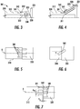
FIG. 3 is schematic axial cross-sectional view of a shaft end joint in accordance with embodiments; -
FIG. 4 is schematic axial cross-sectional view of a shaft end joint in accordance with embodiments; -
FIG. 5 is schematic side view of an array of stripes of a shaft end joint in accordance with embodiments; -
FIG. 6 is schematic side view of an angled stripe of a shaft end joint in accordance with embodiments; -
FIG. 7 is schematic side view of an array of stripes exhibiting axial tensile and torsional deformations of a shaft end joint in accordance with embodiments; -
FIG. 8 is schematic axial cross-sectional view of a shaft end joint in accordance with further embodiments; -
FIG. 9 is schematic side view of an array of stripes of a shaft end joint in accordance with embodiments; -
FIG. 10 is schematic side view of an array of stripes exhibiting axial tensile and torsional movements of a shaft end joint in accordance with embodiments; -
FIG. 11 is schematic side view of an array of stripes exhibiting axial and torsional deformations of a shaft end joint in accordance with embodiments; and -
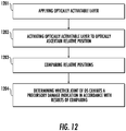
FIG. 12 is a flow diagram illustrating a method of inspecting a joint of an aircraft drive shaft (DS) in accordance with embodiments. - These and other advantages and features will become more apparent from the following description taken in conjunction with the drawings.
- As will be described below, a periodic inspection method is provided for drive shaft (DS) joints, especially those including advanced fiber-reinforced polymer-matrix composite materials, where a high risk of damage exists and severe consequences would be expected in cases of failure. The periodic inspection method is based on an application of at least one of fluorescent, absorbing and reflecting material at external surfaces of metallic parts of the joints (i.e., the sleeves) and at external composite surfaces (i.e., shafts) to monitor boundary gaps where the applied at least one of fluorescent, absorbing and reflecting material effectively serves as a precursor indicator of potential progressive damages. Upon the application of the at least one of the fluorescent, absorbing and reflecting material, this material will provide for optical indications that can reveal gaps and/or misalignments which can be followed up by more systematic inspections.
- With reference to
FIGS. 1A ,1B and 1C , anaircraft 10 includes a power transmission system 11 (seeFIG. 1B ), amain rotor assembly 12 supported by anairframe 14. Theairframe 14 includes an extendingtail 16 which mounts atail rotor assembly 18. Themain rotor assembly 12 includes amain rotor 20 driven about a first axis of rotation A through amain rotor gearbox 22 by apower plant system 24. - The
power plant system 24 generates power available for flight operations. Thepower plant system 24 includes one or more engine packages to drive amain rotor hub 25 of themain rotor 20 and atail rotor 26 of thetail rotor assembly 18. Thepower plant system 24 can include at least one engine package ENGl. Each engine package ENGl can include a gas turbine engine. Gas turbine engines are known and include a combustor and one or more rotatable spools. Each spool can include a turbine driving a compressor and/or an output of the engine. - The
main rotor 20 includes a plurality ofrotor blades 28 mounted or otherwise secured to themain rotor hub 25. Therotor blades 28 are rotatable about the first axis of rotation A to provide propulsion for theaircraft 10. Thetail rotor 26 includes a plurality ofrotor blades 30 mounted or otherwise secured to atail rotor hub 32. Therotor blades 30 are rotatable about a second axis of rotation B to counteract torque generated by rotation of therotor blades 28. - Although a particular rotary-wing aircraft configuration is illustrated and described herein, other configurations such as vertical-lift fan, turbo-prop, tilt-rotor, tilt-wing and fixed-wing aircraft and other systems including wind turbines, industrial power machinery and shipboard couplings can also benefit from the teachings herein.
- The
power transmission system 11 can include one or more drive assemblies to interconnect thepower plant system 24 and therotors power transmission system 11 includes one or more drive assemblies 40, including drive assemblies 40-1 to 40-3. Each drive assembly 40 includes one ormore DSs 42. In the illustrated example,DS 42 of drive assembly 40-1 couples the engine package ENGl to themain rotor gearbox 22. - Drive assembly 40-2 interconnects the
power plant system 24 and thetail rotor 26. Drive assembly 40-2 includes a plurality ofDSs 42 that couple themain rotor gearbox 22 to anintermediate gearbox 44 and atail gearbox 46 to drive thetail rotor 26.Gearboxes respective rotor blades 30 in response to torque communicated by the engine package ENG1. - Each
DS 42 can include onemore couplings 50. Eachcoupling 50 can be a portion of another aircraft component such as a bearing hanger or gearbox, for example. Eachcoupling 50 can be mechanically attached or otherwise secure thedrive shaft 42 to other portions of thepower transmission system 11, such asadjacent DSs 42,gearboxes gearbox gearbox - The
DSs 42 can interconnect or otherwise couple other portions of theaircraft 10. For example, thepower transmission system 11 can include anaccessory gearbox 45 that drives one or more aircraft components oraccessories 47. Drive assembly 40-3 includes at least oneDS 42 that serves as a power takeoff (PTO) shaft to interconnect theaccessory gearbox 45 andpower plant system 24. Example accessories include starters, generators, hydraulic and fuel pumps and environmental control systems. - The
DSs 42 can includes multiple shaft assemblies or endjoints 150 that connectsequential DS sections 151 and are disposed and configured to transmit substantial amounts of torque. As such, the multiple shaft end joints 150 and theDS sections 151 often experience stresses that can damage the components of the multiple shaft end joints 150 and theDS sections 151. The location of theDSs 42 relative to theaircraft 10 and the outer skin of theairframe 14 can make inspection of the multiple shaft end joints 150 and theDS sections 151 difficult. - With reference to
FIGS. 2A, 2B and 2C , the stress and damage that is potentially experienced by one of the multiple shaft end joints 150 (seeFIG. 1C ) is illustrated. As shown inFIG. 2A , shaftperiodic segment 201 is received withinsleeve segment 202 andconnection 203, which can be provided as a radial fastener, a bolt, a pin or a rivet or as adhesive or glue, is used to secure the shaftperiodic segment 201 to thesleeve segment 202. At a certain point in time, as shown inFIG. 2B which is an example of axial tensile loading, initial micro-damages due tostress concentrations 204 are formed proximate to theconnection 203 but would be invisible to an inspection as they would be hidden by thesleeve segment 202. At a next point in time, as shown inFIG. 2C which is a further example of continued axial tensile loading, increased stress concentrations have given way to a crack that resulted in the excessive deformation and the movement of the original boundary between the shaftperiodic segment 201 and thesleeve segment 202. - Damages in one or several locations around connections (i.e., radial fasteners) are usually not sufficient to be considered as limits of structural integrity of the entire shaft configurations. However, they can serve as a valuable precursor of their complete failure under increased load or expanded duration of the load, with clear indications of excessive deformation in at least one or some areas near the original shaft/sleeve boundary.
- Thus, with reference to
FIGS. 3-11 , easily inspected shaft assemblies or end joints (hereinafter referred to as "shaft assemblies") 301 (seeFIGS. 3-7 ) and 801 (seeFIGS. 8-11 ) are provided and allow for inspections that can identify issues well before the complete limit of structural integrity of the entire shaft is reached. - The
shaft assembly 301 includes ashaft 310 that can be made of metallic or composite materials, anexternal sleeve 320 that is coupled to ahousing 321 and is formed to be receptive of a portion of theshaft 310, aconnection 330 and an opticallyactivatable layer 340. Theconnection 330 is disposed to extend through at least thesleeve 320 to secure thesleeve 320 and theshaft 310 together or to secure theshaft 310 between thesleeve 320 and an insert 322 (seeFIG. 3 ). Theshaft 310 can be substantially straight (i.e., with constant diameter) or provided with a conically-shaped section 311 (seeFIG. 4 ). In cases of joints with conical end-section shapes (shown inFIG. 4 as an example), joints can also be implemented without connections (i.e., radial fasteners), since such wedge-type joints are able to transfer axial load including tension. - The optically
activatable layer 340 can be provided as at least one of fluorescent, absorbing and reflecting material, coating or paint that glows or shows dark as a result of electromagnetic radiation being emitted toward it or another similar feature that can be optically activated by light of a corresponding spectrum (e.g., ultraviolet or simply visible). The opticallyactivatable layer 340 includes afirst section 341 and asecond section 342. Thefirst section 341 is disposed on anexterior surface 312 of theshaft 310 and thesecond section 342 is disposed on anexterior surface 323 of thesleeve 320. The first andsecond sections shaft 310 and thesleeve 320 move relative to one another and thus provide optical indications as to an amount of stress and strain and/or internal damage theshaft assembly 301 has experienced. - As shown in
FIG. 5 and 6 , the opticallyactivatable layer 340 can be provided in an array ofstripes 501 that is arranged around theshaft 310 and thesleeve 320. Thesestripes 501 can be parallel with a central longitudinal axis A of theshaft 310 and the sleeve 320 (seeFIG. 5 ) or angled relative to the central longitudinal axis A (seeFIG. 6 ). The stripes can have uniform or variable geometries and may be placed with uniform or variable distances from one another. - As shown in
FIG. 7 , whether thestripes 501 are parallel or angled with respect to the central longitudinal axis A, relative movement between theshaft 310 and thesleeve 320 will result in a corresponding relative displacement of thefirst section 341 and the second section 342 (see the axial Δz and torsional ΔΘ movements ofFIG. 7 ). When the opticallyactivatable layer 340 is optically activated, this relative movement will be visible as a gap or misalignment and will serve as a precursor indication that excessive deformation or damage is experienced by theshaft assembly 301. - As shown in
FIGS. 8-11 , theshaft assembly 801 is similar to theshaft assembly 301 but includes ahousing 810 including anextension 811, a portion of which is receivable within ashaft 820, which can be formed of metallic materials or composite materials and acover 830, which includes afirst end 831, asecond end 832 and atransition section 833 between the first and second ends 831 and 832. In accordance with embodiments, thetransition section 833 of thecover 830 may include different shapes, such as, for example, convex shapes (shown as example inFIG. 8 ), tapered shapes, concave shapes, etc. - The
shaft assembly 801 also includes afirst connector 840, asecond connector 850 and an opticallyactivatable layer 860. The first andsecond connectors FIG. 8 or by an appropriate gluing, since no significant load transfer in this connection is expected. Theextension 811 secures theshaft 820 and thehousing 810 together via thesecond connector 850 which extends through theextension 811 and theshaft 820. The opticallyactivatable layer 860 is similar to theoptical activatable layer 340 and includes afirst section 861 and asecond section 862. Thefirst section 861 is disposed on anexterior surface 821 of theshaft 820 and thesecond section 862 is disposed on thesecond end 832 of thecover 830. The first andsecond sections shaft 820 and thesecond end 832 of thecover 830 move relative to one another. - The optically
activatable layer 860 can be provided in an array ofstripes 901 that are arranged around theshaft 820 and thecover 830. Thestripes 901 can be parallel with a central longitudinal axis A of theshaft 820 and thecover 830 or angled (seeFIG. 6 ) relative to the central longitudinal axis A. Thestripes 901 can have uniform or variable geometries and may be placed with uniform or variable distances from one another. - As shown in
FIG. 10 , whether thestripes 901 are parallel or angled with respect to the central longitudinal axis A, relative movement between theshaft 820 and thecover 830 will result in a corresponding relative movement of thefirst section 861 and the second section 862 (see the axial tensile Δz and torsional ΔΘ misalignments ofFIG. 10 ). When the opticallyactivatable layer 860 is optically activated, this relative movement will be visible and will serve as a precursor indication that internal damage is experienced by theshaft assembly 801. - With reference to
FIG. 11 and in accordance with further embodiments, thesecond end 832 of thecover 830 may be formed to define anaperture 1101 or an array ofapertures 1101 around theshaft 820. In such cases, the opticallyactivatable layer 860 may further include anadditional section 863 that is disposed on a portion of theexterior surface 821 of theshaft 820 that is exposed by eachaperture 1101. This implementation can be especially helpful in case on potential damage primarily due to axial compression load or/and compressive stresses due to bending. In these cases, relative misalignment betweensections 863 and 864 disposed on the opticallyactivatable layer 860 can serve as indication of movement between thecover 830 and theshaft 820. - With reference to
FIG. 12 , a method of inspecting a joint of an aircraft DS at which first and second members are at an initial relative position (i.e., their installation or undamaged position). The method includes applying an optically activatable layer to the joint (1201) by disposing first and second sections of the optically activatable layer on respective exterior surfaces of the first and second members, respectively, such that the first and second sections move relative to one another with relative first and second member movement. After a certain period of time (i.e., a predefined time-in-service), the method also includes repeatedly activating the optically activatable layer to optically ascertain, from relative positions of the first and second sections, a secondary relative position of the first and second members (1202), comparing the secondary and the initial relative positions (1203) and determining whether the joint of the DS exhibits a precursory damage indication in accordance with results of the comparing (1204). - In accordance with embodiments, the optically activatable layer may include at least one of fluorescent, absorbent and reflective materials or coatings or paints and the activating of the optically activatable layer of 1202 may include emitting ultraviolet, visible, or other spectrum light toward these materials, coatings or paints. In addition, the determining of 1204 may include determining that the joint of the DS exhibits the precursory damage indication in accordance with the results of the comparing indicating that the secondary and the initial relative positions are different by a threshold amount.
- Technical effects and benefits of the present disclosure are dramatic cost reductions of DS maintenance for designs with composite materials and the ability to have inspections performed by personnel without special training, without complex equipment and without service interruptions.
- While the disclosure is provided in detail in connection with only a limited number of embodiments, it should be readily understood that the disclosure is not limited to such disclosed embodiments. Rather, the disclosure can be modified to incorporate any number of variations, alterations, substitutions or equivalent arrangements not heretofore described, but which are commensurate with the spirit and scope of the disclosure. Additionally, while various embodiments of the disclosure have been described, it is to be understood that the exemplary embodiment(s) may include only some of the described exemplary aspects. Accordingly, the disclosure is not to be seen as limited by the foregoing description, but is only limited by the scope of the appended claims.
Claims (15)
- An easily inspected shaft assembly, comprising:a shaft (310);a sleeve (320) receptive of a portion of the shaft (310); andan optically activatable layer (340) comprising first and second sections (341, 342) disposed on respective exterior surfaces (312, 323) of the shaft and the sleeve (320), respectively, such that the first and second sections (341, 342) move relative to one another as the shaft (310) and the sleeve (320) move relative to one another.
- The assembly according to claim 1, wherein at least one of the shaft (310) and the sleeve (320) comprises at least one of metallic materials and composite materials; and/or wherein the shaft (310) is secured between the sleeve (320) and an additional member; and/or wherein the optically activatable layer (340) comprises at least one of fluorescent, absorbent and reflective material, coating or paint.
- The assembly according to claims 1 or 2, wherein:the optically activatable layer (340) is provided in an array of one or more stripes (501) of uniform and/or variable geometries arranged around the shaft (310) and the sleeve (320), andthe one or more stripes (501) are parallel with and/or angled relative to a central longitudinal axis of the shaft (310) and the sleeve (320).
- The assembly according to any preceding claim, further comprising one or more connections to secure the sleeve (320) and the shaft (310) together.
- An aircraft, comprising:an engine;a gearbox disposed remotely from the engine; anda drive shaft (DS) configured to transmit torque produced by the engine to the gearbox,wherein the assembly according to claim 1 is provided as one or more assemblies disposed along a length of the DS.
- An easily inspected shaft assembly, comprising:a housing (810) comprising an extension (811);a shaft (820) which is receptive of a portion of the extension (811);a cover (830); andan optically activatable layer (860) comprising first and second sections (861, 862) disposed on respective exterior surfaces (821, 832) of the shaft (820) and the cover (830), respectively, such that the first and second sections (861, 862) move relative to one another as the shaft (820) and the cover (830) move relative to one another.
- The assembly according to claim 6, wherein at least one of the shaft (820), the cover (830) and the housing (810) comprises at least one of metallic materials and composite materials; and/or wherein the optically activatable layer (860) comprises at least one of fluorescent, absorbent and reflective material, coating or paint.
- The assembly according to claims 6 or 7, wherein:the optically activatable layer (860) is provided in an array of one or more stripes (901)) of uniform and/or variable geometries arranged around the shaft (820) and the cover (830), andthe one or more stripes (901) are parallel with and/or angled relative to a central longitudinal axis of the shaft (820) and the cover (830).
- The assembly according to any of claims 6-8, wherein the cover (830) is formed to define one or more apertures, and preferably wherein the optically activatable layer (860) further comprises an additional section disposed on a portion of the exterior surface of the shaft exposed by the one or more apertures, and more preferably wherein:the cover (830) is formed to define an array of one or more apertures around the shaft, andthe optically activatable layer (860) is provided in an array of one or more stripes (901) arranged around the shaft (820) and the cover (830) with each of the one or more stripes extending into a corresponding aperture.
- The assembly according to any of claims 6-9, further comprising:one or more first connections to secure the shaft (820) and the extension (811) together; andone or more second connections to secure the housing (810) and the cover (830) together.
- An aircraft, comprising:an engine;a gearbox disposed remotely from the engine; anda drive shaft (DS) configured to transmit torque produced by the engine to the gearbox,wherein the assembly according to claim 6 is provided as one or more assemblies disposed along a length of the DS.
- A method of inspecting a joint at which first and second members are at an initial relative position, the method comprising:applying an optically activatable layer to the joint,the applying comprising disposing first and second sections of the optically activatable layer on respective exterior surfaces of the first and second members, respectively, such that the first and second sections move relative to one another with relative first and second member movement;activating the optically activatable layer to optically ascertain, from relative positions of the first and second sections, a secondary relative position of the first and second members;comparing the secondary and the initial relative positions; anddetermining whether the joint of the DS exhibits a precursory damage indication in accordance with results of the comparing.
- The method according to claim 12, wherein the activating, the comparing and the determining are repeated periodically following a predefined delay subsequent to the applying.
- The method according to claims 12 or 13, wherein the optically activatable layer comprises at least one of fluorescent, absorbent and reflective material, coating or paint and the activating of the optically activatable layer comprises emitting light toward the optically activatable layer.
- The method according to any of claims 12-14, wherein the determining that the joint of the DS exhibits the precursory damage indication is in accordance with the results of the comparing indicating that the secondary and the initial relative positions are different by a threshold amount.
Priority Applications (1)
| Application Number | Priority Date | Filing Date | Title |
|---|---|---|---|
| EP23185100.7A EP4249760B1 (en) | 2018-09-28 | 2019-09-10 | Design and inspection method of aircraft drive shafts |
Applications Claiming Priority (1)
| Application Number | Priority Date | Filing Date | Title |
|---|---|---|---|
| US16/146,526 US11480528B2 (en) | 2018-09-28 | 2018-09-28 | And inspection method of aircraft drive shafts |
Related Child Applications (1)
| Application Number | Title | Priority Date | Filing Date |
|---|---|---|---|
| EP23185100.7A Division EP4249760B1 (en) | 2018-09-28 | 2019-09-10 | Design and inspection method of aircraft drive shafts |
Publications (2)
| Publication Number | Publication Date |
|---|---|
| EP3628588A1 true EP3628588A1 (en) | 2020-04-01 |
| EP3628588B1 EP3628588B1 (en) | 2023-08-02 |
Family
ID=67909309
Family Applications (2)
| Application Number | Title | Priority Date | Filing Date |
|---|---|---|---|
| EP23185100.7A Active EP4249760B1 (en) | 2018-09-28 | 2019-09-10 | Design and inspection method of aircraft drive shafts |
| EP19196344.6A Active EP3628588B1 (en) | 2018-09-28 | 2019-09-10 | Design and inspection method of aircraft drive shafts |
Family Applications Before (1)
| Application Number | Title | Priority Date | Filing Date |
|---|---|---|---|
| EP23185100.7A Active EP4249760B1 (en) | 2018-09-28 | 2019-09-10 | Design and inspection method of aircraft drive shafts |
Country Status (2)
| Country | Link |
|---|---|
| US (1) | US11480528B2 (en) |
| EP (2) | EP4249760B1 (en) |
Cited By (1)
| Publication number | Priority date | Publication date | Assignee | Title |
|---|---|---|---|---|
| EP4112460A1 (en) * | 2021-07-02 | 2023-01-04 | Goodrich Corporation | Drive shaft with increased ballistic tolerance |
Families Citing this family (2)
| Publication number | Priority date | Publication date | Assignee | Title |
|---|---|---|---|---|
| US11554858B2 (en) * | 2019-06-09 | 2023-01-17 | Textron Innovations Inc. | Rotor mast with composite insert |
| US11892035B2 (en) | 2021-04-23 | 2024-02-06 | Hamilton Sundstrand Corporation | Composite/metal joints |
Family Cites Families (18)
| Publication number | Priority date | Publication date | Assignee | Title |
|---|---|---|---|---|
| US4899596A (en) * | 1988-05-04 | 1990-02-13 | Avco Corporation | Self-calibrating torque measuring system |
| US5456123A (en) * | 1994-01-26 | 1995-10-10 | Simmonds Precision Products, Inc. | Static torque measurement for rotatable shaft |
| US6057618A (en) * | 1998-04-01 | 2000-05-02 | Bell Helicopter Textron, Inc. | Support assembly for a rotating shaft |
| US6150656A (en) | 1998-12-10 | 2000-11-21 | United Technologies Corporation | Method of assembly and inspection for a gas turbine engine |
| US6364772B1 (en) * | 2000-08-22 | 2002-04-02 | Hamilton Sundstrand Corporation | Disconnect for high-speed rotating shafts |
| JP4846103B2 (en) | 2001-02-07 | 2011-12-28 | 三菱レイヨン株式会社 | Fiber reinforced resin pipe and power transmission shaft using the same |
| US7271894B2 (en) | 2003-10-01 | 2007-09-18 | General Electric Company | Imaging system for robotically inspecting gas turbine combustion components |
| US7037072B2 (en) * | 2004-03-03 | 2006-05-02 | Carson Franklin D | Rotor head for a rotary-wing aircraft |
| US7109619B2 (en) * | 2004-03-12 | 2006-09-19 | Bell Helicopter Textron Inc. | Damper support assembly for a supercritical drive shaft |
| US7510377B1 (en) * | 2004-11-16 | 2009-03-31 | Cartercopters, L.L.C. | Rotor aircraft tilting hub with reduced drag rotor head and mast |
| AU2008215172B2 (en) | 2007-02-14 | 2013-05-30 | The Commonwealth Of Australia | Monitoring the structural health of components |
| CA2727382C (en) * | 2008-06-11 | 2016-12-20 | Keith A. Bullin | Downhole motor |
| US9174731B2 (en) * | 2013-08-14 | 2015-11-03 | Bell Helicopter Textron Inc. | Fixed engine and rotating proprotor arrangement for a tiltrotor aircraft |
| CA2863272C (en) * | 2014-09-12 | 2016-10-18 | G.B.D. Corp. | Method of joining pipes and fittings |
| US9739316B2 (en) * | 2015-08-04 | 2017-08-22 | The Boeing Company | Torque tube assemblies for use with aircraft high lift devices |
| DE102016001465A1 (en) * | 2016-02-09 | 2017-08-10 | Giesecke & Devrient Gmbh | Verification of an item provided with a security element |
| US10753884B2 (en) | 2016-06-14 | 2020-08-25 | Rolls-Royce Corporation | Nondestructive inspection of composite materials |
| US10218232B2 (en) * | 2016-11-17 | 2019-02-26 | General Electric Company | High speed electric machine |
-
2018
- 2018-09-28 US US16/146,526 patent/US11480528B2/en active Active
-
2019
- 2019-09-10 EP EP23185100.7A patent/EP4249760B1/en active Active
- 2019-09-10 EP EP19196344.6A patent/EP3628588B1/en active Active
Non-Patent Citations (3)
| Title |
|---|
| ANONYMOUS: "Advanced Automotive Drive Train Troubleshooting and Overhaul", 25 July 2018 (2018-07-25), XP055666380, Retrieved from the Internet <URL:https://www.waybuilder.net/free-ed/SkilledTrades/Automotive/08AdvTroubleTrans/08AdvTroubleTrans.asp> [retrieved on 20200207] * |
| ANONYMOUS: "Schrauben markieren / sicherungsdraht / wie macht ihr es ? - racing4fun.de", 1 June 2016 (2016-06-01), pages 1 - 5, XP055665404, Retrieved from the Internet <URL:https://www.racing4fun.de/forum/viewtopic.php?t=41889> [retrieved on 20200205] * |
| ANONYMOUS: "So SAD -93 All Trac Front Axel preventing SAD shaft removal - Page 2", 5 April 2016 (2016-04-05), pages 8 - 15, XP055665486, Retrieved from the Internet <URL:http://www.toyotavantech.com/forum/showthread.php?436-So-SAD-93-All-Trac-Front-Axel-preventing-SAD-shaft-removal/page2> [retrieved on 20200205] * |
Cited By (2)
| Publication number | Priority date | Publication date | Assignee | Title |
|---|---|---|---|---|
| EP4112460A1 (en) * | 2021-07-02 | 2023-01-04 | Goodrich Corporation | Drive shaft with increased ballistic tolerance |
| US12258122B2 (en) | 2021-07-02 | 2025-03-25 | Goodrich Corporation | Drive shaft with ballistic tolerance |
Also Published As
| Publication number | Publication date |
|---|---|
| EP3628588B1 (en) | 2023-08-02 |
| EP4249760A3 (en) | 2023-11-22 |
| EP4249760B1 (en) | 2026-04-29 |
| EP4249760A2 (en) | 2023-09-27 |
| US20200103351A1 (en) | 2020-04-02 |
| US11480528B2 (en) | 2022-10-25 |
Similar Documents
| Publication | Publication Date | Title |
|---|---|---|
| EP3628588B1 (en) | Design and inspection method of aircraft drive shafts | |
| US6231012B1 (en) | No-back/offset gear box | |
| US5351913A (en) | Coaxial transmission/center hub subassembly for a rotor assembly having ducted, coaxial counter-rotating rotors | |
| US5364230A (en) | Rotor blade subassembly for a rotor assembly having ducted, coaxial counter-rotating rotors | |
| US5226350A (en) | Drive train assembly for a rotor assembly having ducted, coaxial counter-rotating rotors | |
| EP3617064B1 (en) | Ballistic resistant drive shaft | |
| EP0861778A1 (en) | A snubber assembly for an unmanned aerial vehicle | |
| US20100166546A1 (en) | Apparatuses, systems, and methods of gas turbine engine component interconnection | |
| US6279852B1 (en) | Drive system for a propeller driven transport aircraft | |
| US5281099A (en) | Integrated spline/cone seat subassembly for a rotor assembly having ducted, coaxial counter-rotating rotors | |
| US20160176521A1 (en) | Flexbeam rotor attachment to rotor blade | |
| CA2894905C (en) | Embedding fiber optic cables in rotorcraft composites | |
| EP3929553B1 (en) | Pylon engine mount health monitoring system | |
| US20190072106A1 (en) | Fan blade tip with frangible strip | |
| US3472321A (en) | Fan | |
| US20170203837A1 (en) | Drive shaft system hanger bearing | |
| EP2778445B1 (en) | shaft for gearbox systems to limit wear and corrosion | |
| US20190113049A1 (en) | Variable pitch fan for a gas turbine engine | |
| EP4328133B1 (en) | Rotary shaft for an aircraft | |
| US9212679B2 (en) | High shear capability interface | |
| US20200377204A1 (en) | Securing assembly for a rotor blade | |
| US10927899B2 (en) | Splined coupling | |
| US10605631B2 (en) | Structural pi joint with integrated fiber optic sensing | |
| Darmstadt et al. | Composites for advanced drive systems, a systems analysis-Revolutionary vertical lift technology (RVLT) | |
| US11708156B2 (en) | Friction welded raceways for use in rotorcraft propulsion assemblies |
Legal Events
| Date | Code | Title | Description |
|---|---|---|---|
| PUAI | Public reference made under article 153(3) epc to a published international application that has entered the european phase |
Free format text: ORIGINAL CODE: 0009012 |
|
| STAA | Information on the status of an ep patent application or granted ep patent |
Free format text: STATUS: THE APPLICATION HAS BEEN PUBLISHED |
|
| AK | Designated contracting states |
Kind code of ref document: A1 Designated state(s): AL AT BE BG CH CY CZ DE DK EE ES FI FR GB GR HR HU IE IS IT LI LT LU LV MC MK MT NL NO PL PT RO RS SE SI SK SM TR |
|
| AX | Request for extension of the european patent |
Extension state: BA ME |
|
| STAA | Information on the status of an ep patent application or granted ep patent |
Free format text: STATUS: REQUEST FOR EXAMINATION WAS MADE |
|
| 17P | Request for examination filed |
Effective date: 20200929 |
|
| RBV | Designated contracting states (corrected) |
Designated state(s): AL AT BE BG CH CY CZ DE DK EE ES FI FR GB GR HR HU IE IS IT LI LT LU LV MC MK MT NL NO PL PT RO RS SE SI SK SM TR |
|
| STAA | Information on the status of an ep patent application or granted ep patent |
Free format text: STATUS: EXAMINATION IS IN PROGRESS |
|
| 17Q | First examination report despatched |
Effective date: 20210120 |
|
| GRAP | Despatch of communication of intention to grant a patent |
Free format text: ORIGINAL CODE: EPIDOSNIGR1 |
|
| STAA | Information on the status of an ep patent application or granted ep patent |
Free format text: STATUS: GRANT OF PATENT IS INTENDED |
|
| RIC1 | Information provided on ipc code assigned before grant |
Ipc: B64D 35/00 20060101ALN20230201BHEP Ipc: F16D 1/06 20060101ALI20230201BHEP Ipc: B64D 45/08 20060101ALI20230201BHEP Ipc: B64C 27/12 20060101ALI20230201BHEP Ipc: B64C 13/28 20060101AFI20230201BHEP |
|
| RIC1 | Information provided on ipc code assigned before grant |
Ipc: B64D 35/00 20060101ALN20230215BHEP Ipc: F16D 1/06 20060101ALI20230215BHEP Ipc: B64D 45/08 20060101ALI20230215BHEP Ipc: B64C 27/12 20060101ALI20230215BHEP Ipc: B64C 13/28 20060101AFI20230215BHEP |
|
| INTG | Intention to grant announced |
Effective date: 20230227 |
|
| RIN1 | Information on inventor provided before grant (corrected) |
Inventor name: KING, MICHAEL Inventor name: SCHAEFER, JOYEL M. Inventor name: REED, BRAYTON Inventor name: ZAFIRIS, GEORGIOS S. Inventor name: GURVICH, MARK R. |
|
| GRAS | Grant fee paid |
Free format text: ORIGINAL CODE: EPIDOSNIGR3 |
|
| GRAA | (expected) grant |
Free format text: ORIGINAL CODE: 0009210 |
|
| STAA | Information on the status of an ep patent application or granted ep patent |
Free format text: STATUS: THE PATENT HAS BEEN GRANTED |
|
| AK | Designated contracting states |
Kind code of ref document: B1 Designated state(s): AL AT BE BG CH CY CZ DE DK EE ES FI FR GB GR HR HU IE IS IT LI LT LU LV MC MK MT NL NO PL PT RO RS SE SI SK SM TR |
|
| REG | Reference to a national code |
Ref country code: GB Ref legal event code: FG4D |
|
| REG | Reference to a national code |
Ref country code: CH Ref legal event code: EP |
|
| REG | Reference to a national code |
Ref country code: DE Ref legal event code: R096 Ref document number: 602019033915 Country of ref document: DE |
|
| REG | Reference to a national code |
Ref country code: IE Ref legal event code: FG4D |
|
| REG | Reference to a national code |
Ref country code: LT Ref legal event code: MG9D |
|
| REG | Reference to a national code |
Ref country code: NL Ref legal event code: MP Effective date: 20230802 |
|
| REG | Reference to a national code |
Ref country code: AT Ref legal event code: MK05 Ref document number: 1594459 Country of ref document: AT Kind code of ref document: T Effective date: 20230802 |
|
| PG25 | Lapsed in a contracting state [announced via postgrant information from national office to epo] |
Ref country code: GR Free format text: LAPSE BECAUSE OF FAILURE TO SUBMIT A TRANSLATION OF THE DESCRIPTION OR TO PAY THE FEE WITHIN THE PRESCRIBED TIME-LIMIT Effective date: 20231103 |
|
| PG25 | Lapsed in a contracting state [announced via postgrant information from national office to epo] |
Ref country code: IS Free format text: LAPSE BECAUSE OF FAILURE TO SUBMIT A TRANSLATION OF THE DESCRIPTION OR TO PAY THE FEE WITHIN THE PRESCRIBED TIME-LIMIT Effective date: 20231202 |
|
| PG25 | Lapsed in a contracting state [announced via postgrant information from national office to epo] |
Ref country code: SE Free format text: LAPSE BECAUSE OF FAILURE TO SUBMIT A TRANSLATION OF THE DESCRIPTION OR TO PAY THE FEE WITHIN THE PRESCRIBED TIME-LIMIT Effective date: 20230802 Ref country code: RS Free format text: LAPSE BECAUSE OF FAILURE TO SUBMIT A TRANSLATION OF THE DESCRIPTION OR TO PAY THE FEE WITHIN THE PRESCRIBED TIME-LIMIT Effective date: 20230802 Ref country code: PT Free format text: LAPSE BECAUSE OF FAILURE TO SUBMIT A TRANSLATION OF THE DESCRIPTION OR TO PAY THE FEE WITHIN THE PRESCRIBED TIME-LIMIT Effective date: 20231204 Ref country code: NO Free format text: LAPSE BECAUSE OF FAILURE TO SUBMIT A TRANSLATION OF THE DESCRIPTION OR TO PAY THE FEE WITHIN THE PRESCRIBED TIME-LIMIT Effective date: 20231102 Ref country code: NL Free format text: LAPSE BECAUSE OF FAILURE TO SUBMIT A TRANSLATION OF THE DESCRIPTION OR TO PAY THE FEE WITHIN THE PRESCRIBED TIME-LIMIT Effective date: 20230802 Ref country code: LV Free format text: LAPSE BECAUSE OF FAILURE TO SUBMIT A TRANSLATION OF THE DESCRIPTION OR TO PAY THE FEE WITHIN THE PRESCRIBED TIME-LIMIT Effective date: 20230802 Ref country code: LT Free format text: LAPSE BECAUSE OF FAILURE TO SUBMIT A TRANSLATION OF THE DESCRIPTION OR TO PAY THE FEE WITHIN THE PRESCRIBED TIME-LIMIT Effective date: 20230802 Ref country code: IS Free format text: LAPSE BECAUSE OF FAILURE TO SUBMIT A TRANSLATION OF THE DESCRIPTION OR TO PAY THE FEE WITHIN THE PRESCRIBED TIME-LIMIT Effective date: 20231202 Ref country code: HR Free format text: LAPSE BECAUSE OF FAILURE TO SUBMIT A TRANSLATION OF THE DESCRIPTION OR TO PAY THE FEE WITHIN THE PRESCRIBED TIME-LIMIT Effective date: 20230802 Ref country code: GR Free format text: LAPSE BECAUSE OF FAILURE TO SUBMIT A TRANSLATION OF THE DESCRIPTION OR TO PAY THE FEE WITHIN THE PRESCRIBED TIME-LIMIT Effective date: 20231103 Ref country code: FI Free format text: LAPSE BECAUSE OF FAILURE TO SUBMIT A TRANSLATION OF THE DESCRIPTION OR TO PAY THE FEE WITHIN THE PRESCRIBED TIME-LIMIT Effective date: 20230802 Ref country code: AT Free format text: LAPSE BECAUSE OF FAILURE TO SUBMIT A TRANSLATION OF THE DESCRIPTION OR TO PAY THE FEE WITHIN THE PRESCRIBED TIME-LIMIT Effective date: 20230802 |
|
| PG25 | Lapsed in a contracting state [announced via postgrant information from national office to epo] |
Ref country code: PL Free format text: LAPSE BECAUSE OF FAILURE TO SUBMIT A TRANSLATION OF THE DESCRIPTION OR TO PAY THE FEE WITHIN THE PRESCRIBED TIME-LIMIT Effective date: 20230802 |
|
| PG25 | Lapsed in a contracting state [announced via postgrant information from national office to epo] |
Ref country code: ES Free format text: LAPSE BECAUSE OF FAILURE TO SUBMIT A TRANSLATION OF THE DESCRIPTION OR TO PAY THE FEE WITHIN THE PRESCRIBED TIME-LIMIT Effective date: 20230802 |
|
| PG25 | Lapsed in a contracting state [announced via postgrant information from national office to epo] |
Ref country code: SM Free format text: LAPSE BECAUSE OF FAILURE TO SUBMIT A TRANSLATION OF THE DESCRIPTION OR TO PAY THE FEE WITHIN THE PRESCRIBED TIME-LIMIT Effective date: 20230802 Ref country code: RO Free format text: LAPSE BECAUSE OF FAILURE TO SUBMIT A TRANSLATION OF THE DESCRIPTION OR TO PAY THE FEE WITHIN THE PRESCRIBED TIME-LIMIT Effective date: 20230802 Ref country code: ES Free format text: LAPSE BECAUSE OF FAILURE TO SUBMIT A TRANSLATION OF THE DESCRIPTION OR TO PAY THE FEE WITHIN THE PRESCRIBED TIME-LIMIT Effective date: 20230802 Ref country code: EE Free format text: LAPSE BECAUSE OF FAILURE TO SUBMIT A TRANSLATION OF THE DESCRIPTION OR TO PAY THE FEE WITHIN THE PRESCRIBED TIME-LIMIT Effective date: 20230802 Ref country code: DK Free format text: LAPSE BECAUSE OF FAILURE TO SUBMIT A TRANSLATION OF THE DESCRIPTION OR TO PAY THE FEE WITHIN THE PRESCRIBED TIME-LIMIT Effective date: 20230802 Ref country code: CZ Free format text: LAPSE BECAUSE OF FAILURE TO SUBMIT A TRANSLATION OF THE DESCRIPTION OR TO PAY THE FEE WITHIN THE PRESCRIBED TIME-LIMIT Effective date: 20230802 Ref country code: SK Free format text: LAPSE BECAUSE OF FAILURE TO SUBMIT A TRANSLATION OF THE DESCRIPTION OR TO PAY THE FEE WITHIN THE PRESCRIBED TIME-LIMIT Effective date: 20230802 |
|
| REG | Reference to a national code |
Ref country code: CH Ref legal event code: PL |
|
| REG | Reference to a national code |
Ref country code: DE Ref legal event code: R097 Ref document number: 602019033915 Country of ref document: DE |
|
| PG25 | Lapsed in a contracting state [announced via postgrant information from national office to epo] |
Ref country code: LU Free format text: LAPSE BECAUSE OF NON-PAYMENT OF DUE FEES Effective date: 20230910 |
|
| REG | Reference to a national code |
Ref country code: BE Ref legal event code: MM Effective date: 20230930 |
|
| PG25 | Lapsed in a contracting state [announced via postgrant information from national office to epo] |
Ref country code: LU Free format text: LAPSE BECAUSE OF NON-PAYMENT OF DUE FEES Effective date: 20230910 Ref country code: IT Free format text: LAPSE BECAUSE OF FAILURE TO SUBMIT A TRANSLATION OF THE DESCRIPTION OR TO PAY THE FEE WITHIN THE PRESCRIBED TIME-LIMIT Effective date: 20230802 Ref country code: MC Free format text: LAPSE BECAUSE OF FAILURE TO SUBMIT A TRANSLATION OF THE DESCRIPTION OR TO PAY THE FEE WITHIN THE PRESCRIBED TIME-LIMIT Effective date: 20230802 |
|
| PLBE | No opposition filed within time limit |
Free format text: ORIGINAL CODE: 0009261 |
|
| STAA | Information on the status of an ep patent application or granted ep patent |
Free format text: STATUS: NO OPPOSITION FILED WITHIN TIME LIMIT |
|
| REG | Reference to a national code |
Ref country code: IE Ref legal event code: MM4A |
|
| PG25 | Lapsed in a contracting state [announced via postgrant information from national office to epo] |
Ref country code: IE Free format text: LAPSE BECAUSE OF NON-PAYMENT OF DUE FEES Effective date: 20230910 |
|
| 26N | No opposition filed |
Effective date: 20240503 |
|
| PG25 | Lapsed in a contracting state [announced via postgrant information from national office to epo] |
Ref country code: CH Free format text: LAPSE BECAUSE OF NON-PAYMENT OF DUE FEES Effective date: 20230930 |
|
| PG25 | Lapsed in a contracting state [announced via postgrant information from national office to epo] |
Ref country code: IE Free format text: LAPSE BECAUSE OF NON-PAYMENT OF DUE FEES Effective date: 20230910 Ref country code: CH Free format text: LAPSE BECAUSE OF NON-PAYMENT OF DUE FEES Effective date: 20230930 Ref country code: SI Free format text: LAPSE BECAUSE OF FAILURE TO SUBMIT A TRANSLATION OF THE DESCRIPTION OR TO PAY THE FEE WITHIN THE PRESCRIBED TIME-LIMIT Effective date: 20230802 |
|
| PG25 | Lapsed in a contracting state [announced via postgrant information from national office to epo] |
Ref country code: BE Free format text: LAPSE BECAUSE OF NON-PAYMENT OF DUE FEES Effective date: 20230930 |
|
| PG25 | Lapsed in a contracting state [announced via postgrant information from national office to epo] |
Ref country code: BG Free format text: LAPSE BECAUSE OF FAILURE TO SUBMIT A TRANSLATION OF THE DESCRIPTION OR TO PAY THE FEE WITHIN THE PRESCRIBED TIME-LIMIT Effective date: 20230802 |
|
| PG25 | Lapsed in a contracting state [announced via postgrant information from national office to epo] |
Ref country code: BG Free format text: LAPSE BECAUSE OF FAILURE TO SUBMIT A TRANSLATION OF THE DESCRIPTION OR TO PAY THE FEE WITHIN THE PRESCRIBED TIME-LIMIT Effective date: 20230802 |
|
| PG25 | Lapsed in a contracting state [announced via postgrant information from national office to epo] |
Ref country code: CY Free format text: LAPSE BECAUSE OF FAILURE TO SUBMIT A TRANSLATION OF THE DESCRIPTION OR TO PAY THE FEE WITHIN THE PRESCRIBED TIME-LIMIT; INVALID AB INITIO Effective date: 20190910 |
|
| PG25 | Lapsed in a contracting state [announced via postgrant information from national office to epo] |
Ref country code: HU Free format text: LAPSE BECAUSE OF FAILURE TO SUBMIT A TRANSLATION OF THE DESCRIPTION OR TO PAY THE FEE WITHIN THE PRESCRIBED TIME-LIMIT; INVALID AB INITIO Effective date: 20190910 |
|
| PGFP | Annual fee paid to national office [announced via postgrant information from national office to epo] |
Ref country code: DE Payment date: 20250820 Year of fee payment: 7 |
|
| PGFP | Annual fee paid to national office [announced via postgrant information from national office to epo] |
Ref country code: GB Payment date: 20250820 Year of fee payment: 7 |
|
| PGFP | Annual fee paid to national office [announced via postgrant information from national office to epo] |
Ref country code: FR Payment date: 20250820 Year of fee payment: 7 |
|
| PG25 | Lapsed in a contracting state [announced via postgrant information from national office to epo] |
Ref country code: TR Free format text: LAPSE BECAUSE OF FAILURE TO SUBMIT A TRANSLATION OF THE DESCRIPTION OR TO PAY THE FEE WITHIN THE PRESCRIBED TIME-LIMIT Effective date: 20230802 |
|
| P01 | Opt-out of the competence of the unified patent court (upc) registered |
Free format text: CASE NUMBER: UPC_APP_0018884_3628588/2025 Effective date: 20251222 |