EP3628585B1 - Cable retainer apparatus and method for retaining a cable - Google Patents
Cable retainer apparatus and method for retaining a cable Download PDFInfo
- Publication number
- EP3628585B1 EP3628585B1 EP19199432.6A EP19199432A EP3628585B1 EP 3628585 B1 EP3628585 B1 EP 3628585B1 EP 19199432 A EP19199432 A EP 19199432A EP 3628585 B1 EP3628585 B1 EP 3628585B1
- Authority
- EP
- European Patent Office
- Prior art keywords
- cable
- cable retainer
- wing
- aircraft
- retainer
- Prior art date
- Legal status (The legal status is an assumption and is not a legal conclusion. Google has not performed a legal analysis and makes no representation as to the accuracy of the status listed.)
- Active
Links
Images

Classifications
-
- B—PERFORMING OPERATIONS; TRANSPORTING
- B64—AIRCRAFT; AVIATION; COSMONAUTICS
- B64C—AEROPLANES; HELICOPTERS
- B64C7/00—Structures or fairings not otherwise provided for
-
- B—PERFORMING OPERATIONS; TRANSPORTING
- B64—AIRCRAFT; AVIATION; COSMONAUTICS
- B64D—EQUIPMENT FOR FITTING IN OR TO AIRCRAFT; FLIGHT SUITS; PARACHUTES; ARRANGEMENT OR MOUNTING OF POWER PLANTS OR PROPULSION TRANSMISSIONS IN AIRCRAFT
- B64D41/00—Power installations for auxiliary purposes
-
- B—PERFORMING OPERATIONS; TRANSPORTING
- B64—AIRCRAFT; AVIATION; COSMONAUTICS
- B64C—AEROPLANES; HELICOPTERS
- B64C1/00—Fuselages; Constructional features common to fuselages, wings, stabilising surfaces or the like
- B64C1/26—Attaching the wing or tail units or stabilising surfaces
-
- F—MECHANICAL ENGINEERING; LIGHTING; HEATING; WEAPONS; BLASTING
- F16—ENGINEERING ELEMENTS AND UNITS; GENERAL MEASURES FOR PRODUCING AND MAINTAINING EFFECTIVE FUNCTIONING OF MACHINES OR INSTALLATIONS; THERMAL INSULATION IN GENERAL
- F16L—PIPES; JOINTS OR FITTINGS FOR PIPES; SUPPORTS FOR PIPES, CABLES OR PROTECTIVE TUBING; MEANS FOR THERMAL INSULATION IN GENERAL
- F16L3/00—Supports for pipes, cables or protective tubing, e.g. hangers, holders, clamps, cleats, clips, brackets
- F16L3/08—Supports for pipes, cables or protective tubing, e.g. hangers, holders, clamps, cleats, clips, brackets substantially surrounding the pipe, cable or protective tubing
- F16L3/10—Supports for pipes, cables or protective tubing, e.g. hangers, holders, clamps, cleats, clips, brackets substantially surrounding the pipe, cable or protective tubing divided, i.e. with two members engaging the pipe, cable or protective tubing
- F16L3/1058—Supports for pipes, cables or protective tubing, e.g. hangers, holders, clamps, cleats, clips, brackets substantially surrounding the pipe, cable or protective tubing divided, i.e. with two members engaging the pipe, cable or protective tubing one member being flexible or elastic
-
- F—MECHANICAL ENGINEERING; LIGHTING; HEATING; WEAPONS; BLASTING
- F16—ENGINEERING ELEMENTS AND UNITS; GENERAL MEASURES FOR PRODUCING AND MAINTAINING EFFECTIVE FUNCTIONING OF MACHINES OR INSTALLATIONS; THERMAL INSULATION IN GENERAL
- F16L—PIPES; JOINTS OR FITTINGS FOR PIPES; SUPPORTS FOR PIPES, CABLES OR PROTECTIVE TUBING; MEANS FOR THERMAL INSULATION IN GENERAL
- F16L3/00—Supports for pipes, cables or protective tubing, e.g. hangers, holders, clamps, cleats, clips, brackets
- F16L3/26—Supports for pipes, cables or protective tubing, e.g. hangers, holders, clamps, cleats, clips, brackets specially adapted for supporting the pipes all along their length, e.g. pipe channels or ducts
-
- B—PERFORMING OPERATIONS; TRANSPORTING
- B64—AIRCRAFT; AVIATION; COSMONAUTICS
- B64C—AEROPLANES; HELICOPTERS
- B64C1/00—Fuselages; Constructional features common to fuselages, wings, stabilising surfaces or the like
- B64C1/36—Fuselages; Constructional features common to fuselages, wings, stabilising surfaces or the like adapted to receive antennas or radomes
-
- B—PERFORMING OPERATIONS; TRANSPORTING
- B64—AIRCRAFT; AVIATION; COSMONAUTICS
- B64C—AEROPLANES; HELICOPTERS
- B64C1/00—Fuselages; Constructional features common to fuselages, wings, stabilising surfaces or the like
- B64C1/38—Constructions adapted to reduce effects of aerodynamic or other external heating
-
- B—PERFORMING OPERATIONS; TRANSPORTING
- B64—AIRCRAFT; AVIATION; COSMONAUTICS
- B64C—AEROPLANES; HELICOPTERS
- B64C1/00—Fuselages; Constructional features common to fuselages, wings, stabilising surfaces or the like
- B64C1/40—Sound or heat insulation, e.g. using insulation blankets
- B64C1/403—Arrangement of fasteners specially adapted therefor, e.g. of clips
- B64C1/406—Arrangement of fasteners specially adapted therefor, e.g. of clips in combination with supports for lines, e.g. for pipes or cables
-
- B—PERFORMING OPERATIONS; TRANSPORTING
- B64—AIRCRAFT; AVIATION; COSMONAUTICS
- B64C—AEROPLANES; HELICOPTERS
- B64C3/00—Wings
- B64C3/26—Construction, shape, or attachment of separate skins, e.g. panels
-
- B—PERFORMING OPERATIONS; TRANSPORTING
- B64—AIRCRAFT; AVIATION; COSMONAUTICS
- B64D—EQUIPMENT FOR FITTING IN OR TO AIRCRAFT; FLIGHT SUITS; PARACHUTES; ARRANGEMENT OR MOUNTING OF POWER PLANTS OR PROPULSION TRANSMISSIONS IN AIRCRAFT
- B64D2221/00—Electric power distribution systems onboard aircraft
-
- H—ELECTRICITY
- H02—GENERATION; CONVERSION OR DISTRIBUTION OF ELECTRIC POWER
- H02G—INSTALLATION OF ELECTRIC CABLES OR LINES, OR OF COMBINED OPTICAL AND ELECTRIC CABLES OR LINES
- H02G3/00—Installations of electric cables or lines or protective tubing therefor in or on buildings, equivalent structures or vehicles
- H02G3/30—Installations of cables or lines on walls, floors or ceilings
- H02G3/32—Installations of cables or lines on walls, floors or ceilings using mounting clamps
Definitions
- the technical field relates generally to retaining a cable, and more particularly, relates to cable retainer apparatuses for retaining a cable, for example from an antenna mounted on a wing, of an aircraft, and aircraft and methods including such apparatuses.
- a cable e.g., coaxial cable
- a controller for communication between the corresponding antenna or other component and the controller.
- wet wings that include at least a portion of a fuel tank for fuel storage. Such aircraft wings are commonly referred to as "wet wings.”
- wet wings When an antenna or other component is mounted on a wet wing, for example to the mid-core section on the lower outer surface of the wing directly below the fuel tank, routing of a cable from the antenna or other component to inside the fuselage to the controller becomes more challenging.
- US 4258515 relates to trunking intended to receive and conceal one or more elongated cables, pipes, conduits or the like on exposed surfaces of walls, architraves, panels or other building or architectual fittings.
- US 2010308169 is concerned with an aircraft wire fairing having an electrical wire embedded therein.
- GB2540792 relates to a vehicle fairing including an electrical routing.
- US 6343954 relates to harness assemblies for electrically joining various sections of high performance missile systems.
- US 2012137653 relates to raceway harness assemblies suitable for use in multi-stage rockets and missiles.
- US 2005230547 relates to a drainmast assembly for ejecting potable waste water (i.e., gray water) from an onboard potable water system of an aircraft.
- US 5456199 relates to an apparatus for reducing aero/hydrodynamic drag on cylindrical objects.
- a cable retainer apparatus for retaining a cable proximate a surface of an aircraft, an aircraft including such a cable retainer apparatus, and a method for retaining a cable from an antenna or other component that is disposed on a wing of an aircraft, are provided herein.
- the cable retainer apparatus includes, but is not limited to, a cable retainer as above that retains the proximal section of the cable.
- the cable retainer apparatus further includes, but is not limited to, a fairing that is coupled to the aircraft and that is disposed about the cable retainer to support the cable retainer adjacent to the outer surface of the wing.
- the method includes, but is not limited to, disposing a cable retainer as above adjacent to the antenna or other component.
- the method further includes, but is not limited to, advancing the cable into the cable channel disposed in the cable retainer.
- the method further includes, but is not limited to, coupling a fairing to the wing about the cable retainer.
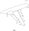
- FIG. 1 illustrates a perspective top view of a portion of an aircraft 10 in accordance with an exemplary embodiment.
- the aircraft 10 includes a fuselage 12 as the main body of the aircraft 10 that supports the wings 14 (only one wing shown) and tail (not shown).
- the wings 14 extend outwardly (outboard direction indicated by single headed arrow 15 shown in FIG. 2 ) from the fuselage 12.
- the engines 16 (only one shown) may be attached to the wings 14, or alternatively, to the fuselage 12.
- An antenna 36 is disposed on the wet wing portion 30 of the lower outer surface 22 of the wing 14 directly below the fuel tank 32.
- a cable 38 e.g., coaxial cable, that is coupled to the antenna 36 and extends therefrom. As illustrated, the cable has a proximal end section 40 disposed adjacent to the antenna 36 and extends to a distal end section 42 towards the fuselage 12.
- the cable retainer apparatus 18 is coupled to the lower outer surface 22 of the wing 14 adjacent to the antenna 36 and retains the proximal end section 40 of the cable 38. As illustrated, the cable retainer apparatus 18 extends between the antenna 36 and the leading edge portion 24, which extends forward (forward direction indicated by single headed arrow 44) of the wet wing portion 30 past the fuel boundary 34, to retain and guide the cable 38 from the antenna 36 past the fuel boundary 34.
- the cable retainer apparatus 18 functions as a fuel barrier (e.g., additional fuel boundary) and provides retention of the proximal end section 40 of the cable 38 and further separation between the cable 38, which is disposed on the exterior portion of the wing 14, and the fuel tank 32, which is disposed on the inside of the wing 14.
- the distal end section 42 of the cable 38 which is disposed past both the cable retainer apparatus 18 and the fuel boundary 34 and therefore is not near the fuel tank 32, may be routed through the interior structure 46 of the leading edge portion 24 of the wing 14 towards the fuselage 12.
- the cable retainer apparatus 18 is being described as retaining a cable 38 from an antenna 36 or other component to the leading edge portion 24 of the wing 14, other embodiments may use the cable retainer apparatus 18 as described herein for retaining a cable 38 from an antenna 36 or other component to the trailing edge portion 26.
- the cable retainer apparatus 38 includes a cable retainer 48 that retains the proximal section 40 of the cable 38, and a fairing 50 (e.g., relatively rigid material, for example plastic, composite, metal or aluminum or other rigid material sheet curved or otherwise formed to fit over the cable retainer 48) that is coupled to the aircraft 10 and disposed about the cable retainer 48 to support the cable retainer 48 adjacent to the lower outer surface 22 of the wing 14.
- the cable retainer 48 is formed of a relatively compliant or flexible material that is fuel resistant.
- the cable retainer 48 may be formed of an elastomeric material for example rubber, a polymeric material, and/or a composite material.
- Nitrile rubber is an example of an elastomeric material that has excellent fuel resistant.
- the cable retainer material has a hardness durometer of about or less than about 80 Shore A, such as from about 50 Shore A to about 80 Shore A, such as from about 50 Shore A to about 75 Shore A, for example from about 56 Shore A to about 72 Shore A.
- the cable retainer 48 has a relatively low profile aerodynamic shape so as to have minimal effect on airflow across the lower outer surface 22 of the wing 14.
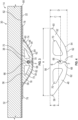
- the cable retainer 48 is an extruded or elongated body 52 having a cross-section with a substantially "D"-shaped outer profile 54 including a substantially linear section 56 coupled to opposing ends 58 and 60 of a substantially curved section 62.
- the substantially linear section 56 interfaces with the lower outer surface 22, e.g., outer skin surface, of the wing 14 of the aircraft 10 while the substantially curved section 62 interfaces with an inner surface 64 of the fairing 50.
- Other relatively low profile aerodynamic cross-sectional shapes for the cable retainer 48 may also be used.
- the cable retainer 48 has a length of from about 61cm to 183cm, for example, 91cm to 122cm, and may be continuous monolithic piece or may be formed in sections that are abutted end to end to form the elongated body 52.
- the cable retainer 48 encases the proximal end section 40 of the cable 14 to shield the cable 14 from exposure to a fuel component, e.g., fuel leakage component, or the like.
- the cable retainer 48 has a cable channel 66 that retains the proximal end section 40 of the cable 14 and that extends longitudinally through the cable retainer 48 to route the cable 14 from the antenna 36 past the fuel boundary 34 to the leading edge portion 24 of the wing 14.
- Opposing positive features 68 and 70 e.g., ribs, lips, nibs or the like
- a gap F is present between the opposing positive features 68 and 70 when in the nominal position.
- the gap F is from about 0,5mm to about 1,5mm, for example about 1mm.
- the cable retainer 48 has the following dimensions A of from about 89mm to about 102mm, for example about 94,5mm dimension B of greater than 12,7mm, for example about 12,9mm or greater, such as about 12,9mm to about 15,2mm to provide continuous positive separation between the cable 14 and the lower outer surface 22 of the wing 14 under the fuel tank 32, dimension C of about 22,9mm to 28mm, for example from about 24mm to about 25,4mm, such as about 24,6mm to provide a relatively low profile shape, and diameter E of about 3,8mm to about 6,35mm.
- the cable retainer 48 may have one or more holes 70 formed therein spaced apart from the cable channel 66, for example to facilitate manufacturing, and/or reducing weight of the cable retainer 48.
- the hole(s) 70 may be elongated in the longitudinal direction of the cable retainer 48, for example as formed during an extrusion process, and may have any variety of cross-sectional shapes including a triangular or substantially triangular shape, other polygonal or substantially polygonal shape, curved or substantially curved shape, or the like.
- the cable retainer 48 may not have any holes formed therein spaced apart from the cable channel 66.
- the cable retainer 48 and fairing 50 are cooperatively configured such that when the fairing 50 is coupled to the aircraft 10, there is an interference fit between the cable retainer 48 and the fairing 50, for example by having the volume formed between the inner surface 64 of the fairing 50 and the corresponding portion of the lower outer surface 22 of the wing 14 being slightly less than the volume defined by the outer profile 54 of the cable retainer 48.
- the cable retainer 48 is slightly oversized relative to the volume provided by the fairing 50, thereby applying a compressive force to the cable retainer 48 when the fairing 50 is coupled to the lower outer surface 22 of the wing 14 to close off the gap F between the opposing positive features 68 and 70 and forming a sealingly tight fit to prevent the cable 14 from being exposed to a fuel component, fuel leakage component, or the like.
- the interference fit between the cable 14 and the cable retainer 48 for example by having the diameter of the cable channel 66 slightly less than the diameter of the cable 14.
- the interference fit between the cable 14 and the cable retainer 48 prevents the cable 14 from vibrating within the cable retainer 48.
- the fairing 50 has a curved section 74 that interfaces with the cable retainer 48 and flange sections 76 and 78 that extend outwardly in opposite directions from the curved section 74 and that interface with the lower outer surface 22 of the wing 14.
- the wing 14 includes a skin 80 having the lower outer surface 22 and an inner surface 82 that is opposite the lower outer surface 22.
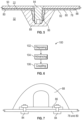
- a plurality of fasteners 84 extends through the flange sections 76 and 78 of the fairing 50 and the skin 80 into corresponding nut plates 86 to couple the fairing 50 to the wing 14.
- nut plates 86 are disposed on the inner surface 82 of the skin 80 and a fuel tank sealant 88 is disposed over each of the nut plates 86 to seal the cable retainer apparatus 38 from any fuel leakage from the attachment areas.
- Fig. 7 illustrates an alternative design for a nut plate 86.
- a method 100 for retaining a cable from an antenna that is disposed on a wing of an aircraft includes disposing (STEP 102) a cable retainer adjacent to the antenna.
- the cable from the antenna is advanced (STEP 104) into a cable channel that is disposed in the cable retainer.
- the cable is advanced into the cable channel by manually pressing the cable against opposing positive features that are disposed adjacent to the cable channel to move the opposing positive features from a nominal position away from each other for arranging the cable in the cable channel.
- a fairing is coupled (STEP 106) to the wing about the cable retainer.
Landscapes
- Engineering & Computer Science (AREA)
- General Engineering & Computer Science (AREA)
- Aviation & Aerospace Engineering (AREA)
- Mechanical Engineering (AREA)
- Details Of Aerials (AREA)
Description
- The technical field relates generally to retaining a cable, and more particularly, relates to cable retainer apparatuses for retaining a cable, for example from an antenna mounted on a wing, of an aircraft, and aircraft and methods including such apparatuses.
- In the aircraft industry, antennas and other components are often attached to the lower outer surfaces of aircraft wings. A cable, e.g., coaxial cable, is typically routed from each antenna or other component to inside the fuselage to a controller for communication between the corresponding antenna or other component and the controller.
- Many aircraft have wings that include at least a portion of a fuel tank for fuel storage. Such aircraft wings are commonly referred to as "wet wings." When an antenna or other component is mounted on a wet wing, for example to the mid-core section on the lower outer surface of the wing directly below the fuel tank, routing of a cable from the antenna or other component to inside the fuselage to the controller becomes more challenging.
- One way to route a cable from an antenna or other component mounted on a wet wing is through the interior structure portion of the wing adj acent to the fuel tank. However, FAA regulations, specifically CFR 25.981 entitled "Fuel Tank Ignition Prevention," require testing to confirm that any new designs to the aircraft structure or system do not induce a source of ignition that could ignite a fuel component (e.g., fuel vapor and/or liquid) in and/or around the fuel tank. As such, other approaches for routing a cable from an antenna or other component mounted on a wet wing that do not require additional testing per FAA regulations would be advantageous.
US 4258515 relates to trunking intended to receive and conceal one or more elongated cables, pipes, conduits or the like on exposed surfaces of walls, architraves, panels or other building or architectual fittings.
US 2010308169 is concerned with an aircraft wire fairing having an electrical wire embedded therein.
GB2540792
US 6343954 relates to harness assemblies for electrically joining various sections of high performance missile systems.
US 2012137653 relates to raceway harness assemblies suitable for use in multi-stage rockets and missiles.
US 2005230547 relates to a drainmast assembly for ejecting potable waste water (i.e., gray water) from an onboard potable water system of an aircraft.
US 5456199 relates to an apparatus for reducing aero/hydrodynamic drag on cylindrical objects. - Accordingly, it is desirable to provide apparatuses for retaining a cable, for example away from a fuel tank on a wing, of an aircraft, and aircraft and methods including such apparatuses. Furthermore, other desirable features and characteristics of the various embodiments described herein will become apparent from the subsequent detailed description and the appended claims, taken in conjunction with the accompanying drawings and this background.
- Various non-limiting embodiments of a cable retainer apparatus for retaining a cable proximate a surface of an aircraft, an aircraft including such a cable retainer apparatus, and a method for retaining a cable from an antenna or other component that is disposed on a wing of an aircraft, are provided herein.
- In a first non-limiting embodiment, the cable retainer apparatus includes, but is not limited to, a cable retainer having a cable channel that extends longitudinally through the cable retainer that is configured to receive and retain the cable. The cable retainer apparatus further includes, but is not limited to, a fairing that is disposed about the cable retainer. The fairing is configured to couple to the aircraft to support the cable retainer adjacent to the surface of the aircraft, and the cable retainer and fairing are cooperatively configured such that when the fairing is coupled to the aircraft, a first interference fit is defined between the cable retainer and the fairing, and a second interference fit is defined between the cable and the cable retainer.
- In another non-limiting embodiment, the aircraft includes, but is not limited to, a fuselage. The aircraft further includes, but is not limited to, a wing extending outward from the fuselage and having an outer surface. The aircraft further includes, but is not limited to, an antenna or other component disposed on the wing. The aircraft further includes, but is not limited to, a cable having a proximal section extending to a distal section. The proximal section is disposed adjacent to the antenna or other component and the distal section extends towards the fuselage. The aircraft further includes, but is not limited to, a cable retainer apparatus as above that is coupled to the outer surface of the wing adjacent to the antenna or other component. The cable retainer apparatus includes, but is not limited to, a cable retainer as above that retains the proximal section of the cable. The cable retainer apparatus further includes, but is not limited to, a fairing that is coupled to the aircraft and that is disposed about the cable retainer to support the cable retainer adjacent to the outer surface of the wing.
- In another non-limiting embodiment, the method includes, but is not limited to, disposing a cable retainer as above adjacent to the antenna or other component. The method further includes, but is not limited to, advancing the cable into the cable channel disposed in the cable retainer. The method further includes, but is not limited to, coupling a fairing to the wing about the cable retainer.
- The various embodiments will hereinafter be described in conjunction with the following drawing figures, wherein like numerals denote like elements, and wherein:
-
FIG. 1 illustrates a perspective top view of a portion of an aircraft in accordance with an exemplary embodiment; -
FIG. 2 illustrates a perspective bottom view of a portion of a wing including a cable retainer apparatus in accordance with an exemplary embodiment; -
FIG. 3 illustrates a cross-sectional view of the portion of the wing including the cable retainer apparatus depicted inFIG. 2 along line 3-3; -
FIG. 4 illustrates a cross-sectional view of a cable retainer of the cable retainer apparatus depicted inFIG. 3 ; -
FIG. 5 illustrates a cross-sectional view of the portion of the wing including the cable retainer apparatus depicted inFIG. 2 along line 5-5 including a nut plate; -
FIG. 6 illustrates a method for retaining a cable from an antenna that is disposed in a wing of an aircraft in aircraft in accordance with an exemplary embodiment; and -
FIG. 7 illustrates a cross-sectional view of the portion of the wing including the cable retainer apparatus depicted inFIG. 2 along line 5-5 with an alternate nut plate design. - The following Detailed Description is merely exemplary in nature and is not intended to limit the various embodiments or the application and uses thereof. Furthermore, there is no intention to be bound by any theory presented in the preceding background or the following detailed description.
-
FIG. 1 illustrates a perspective top view of a portion of anaircraft 10 in accordance with an exemplary embodiment. Theaircraft 10 includes afuselage 12 as the main body of theaircraft 10 that supports the wings 14 (only one wing shown) and tail (not shown). Thewings 14 extend outwardly (outboard direction indicated by singleheaded arrow 15 shown inFIG. 2 ) from thefuselage 12. Depending on the design of theaircraft 10, the engines 16 (only one shown) may be attached to thewings 14, or alternatively, to thefuselage 12. -
FIG. 2 illustrates a perspective bottom view of a portion of thewing 14 including acable retainer apparatus 18 in accordance with an exemplary embodiment. Referring toFIGS. 1-2 , thewing 14 has an upperouter surface 20 and a lowerouter surface 22 opposite the upperouter surface 20. The upper and lowerouter surfaces edge portion 24 and atrailing edge portion 26 of thewing 14. In an exemplary embodiment, thewing 14 is awet wing 28 that includes awet wing portion 30, which includes at least a portion of afuel tank 32 disposed therein between the lower and upperouter surfaces fuel tank 32 defining afuel boundary 34. Anantenna 36 is disposed on thewet wing portion 30 of the lowerouter surface 22 of thewing 14 directly below thefuel tank 32. Acable 38 , e.g., coaxial cable, that is coupled to theantenna 36 and extends therefrom. As illustrated, the cable has aproximal end section 40 disposed adjacent to theantenna 36 and extends to adistal end section 42 towards thefuselage 12. - In an exemplary embodiment, the
cable retainer apparatus 18 is coupled to the lowerouter surface 22 of thewing 14 adjacent to theantenna 36 and retains theproximal end section 40 of thecable 38. As illustrated, thecable retainer apparatus 18 extends between theantenna 36 and the leadingedge portion 24, which extends forward (forward direction indicated by single headed arrow 44) of thewet wing portion 30 past thefuel boundary 34, to retain and guide thecable 38 from theantenna 36 past thefuel boundary 34. In an exemplary embodiment, thecable retainer apparatus 18 functions as a fuel barrier (e.g., additional fuel boundary) and provides retention of theproximal end section 40 of thecable 38 and further separation between thecable 38, which is disposed on the exterior portion of thewing 14, and thefuel tank 32, which is disposed on the inside of thewing 14. Thedistal end section 42 of thecable 38 which is disposed past both thecable retainer apparatus 18 and thefuel boundary 34 and therefore is not near thefuel tank 32, may be routed through theinterior structure 46 of the leadingedge portion 24 of thewing 14 towards thefuselage 12. Note, it is to be understood that although thecable retainer apparatus 18 is being described as retaining acable 38 from anantenna 36 or other component to the leadingedge portion 24 of thewing 14, other embodiments may use thecable retainer apparatus 18 as described herein for retaining acable 38 from anantenna 36 or other component to thetrailing edge portion 26. - Referring to
FIGS. 1-4 , in an exemplary embodiment, thecable retainer apparatus 38 includes acable retainer 48 that retains theproximal section 40 of thecable 38, and a fairing 50 (e.g., relatively rigid material, for example plastic, composite, metal or aluminum or other rigid material sheet curved or otherwise formed to fit over the cable retainer 48) that is coupled to theaircraft 10 and disposed about thecable retainer 48 to support thecable retainer 48 adjacent to the lowerouter surface 22 of thewing 14. In an exemplary embodiment, thecable retainer 48 is formed of a relatively compliant or flexible material that is fuel resistant. For example, thecable retainer 48 may be formed of an elastomeric material for example rubber, a polymeric material, and/or a composite material. Nitrile rubber is an example of an elastomeric material that has excellent fuel resistant. In an exemplary embodiment, the cable retainer material has a hardness durometer of about or less than about 80 Shore A, such as from about 50 Shore A to about 80 Shore A, such as from about 50 Shore A to about 75 Shore A, for example from about 56 Shore A to about 72 Shore A. - In an exemplary embodiment, the
cable retainer 48 has a relatively low profile aerodynamic shape so as to have minimal effect on airflow across the lowerouter surface 22 of thewing 14. In one example, thecable retainer 48 is an extruded orelongated body 52 having a cross-section with a substantially "D"-shapedouter profile 54 including a substantiallylinear section 56 coupled to opposing ends 58 and 60 of a substantiallycurved section 62. As illustrated, the substantiallylinear section 56 interfaces with the lowerouter surface 22, e.g., outer skin surface, of thewing 14 of theaircraft 10 while the substantiallycurved section 62 interfaces with aninner surface 64 of thefairing 50. Other relatively low profile aerodynamic cross-sectional shapes for thecable retainer 48 may also be used. - In an exemplary embodiment, the
cable retainer 48 has a length of from about 61cm to 183cm, for example, 91cm to 122cm, and may be continuous monolithic piece or may be formed in sections that are abutted end to end to form theelongated body 52. In an exemplary embodiment, thecable retainer 48 encases theproximal end section 40 of thecable 14 to shield thecable 14 from exposure to a fuel component, e.g., fuel leakage component, or the like. - In an exemplary embodiment, the
cable retainer 48 has acable channel 66 that retains theproximal end section 40 of thecable 14 and that extends longitudinally through thecable retainer 48 to route thecable 14 from theantenna 36 past thefuel boundary 34 to theleading edge portion 24 of thewing 14. Opposingpositive features 68 and 70 (e.g., ribs, lips, nibs or the like) are disposed adjacent to thecable channel 66 and are substantially elastic or flexible such that the opposingpositive features cable 14 in thecable channel 66 and spring back or return to the nominal position to retain thecable 14 in thecable channel 66. - As illustrated in
FIG. 4 , to facilitate positioning thecable 14 into thecable channel 66 of thecable retainer 48, a gap F is present between the opposingpositive features - Further and as illustrated, in an exemplary embodiment, the
cable retainer 48 has the following dimensions A of from about 89mm to about 102mm, for example about 94,5mm dimension B of greater than 12,7mm, for example about 12,9mm or greater, such as about 12,9mm to about 15,2mm to provide continuous positive separation between thecable 14 and the lowerouter surface 22 of thewing 14 under thefuel tank 32, dimension C of about 22,9mm to 28mm, for example from about 24mm to about 25,4mm, such as about 24,6mm to provide a relatively low profile shape, and diameter E of about 3,8mm to about 6,35mm. - It is to be understood that the dimensions provided above are non-limiting, and other suitable dimensions (A-F) for the
cable retainer 48 may be used without departing from various embodiments described herein. - As illustrated in
FIGS. 3-4 , thecable retainer 48 may have one ormore holes 70 formed therein spaced apart from thecable channel 66, for example to facilitate manufacturing, and/or reducing weight of thecable retainer 48. The hole(s) 70 may be elongated in the longitudinal direction of thecable retainer 48, for example as formed during an extrusion process, and may have any variety of cross-sectional shapes including a triangular or substantially triangular shape, other polygonal or substantially polygonal shape, curved or substantially curved shape, or the like. Alternatively, thecable retainer 48 may not have any holes formed therein spaced apart from thecable channel 66. - Referring to
FIGS. 2-3 and5 , thecable retainer 48 and fairing 50 are cooperatively configured such that when the fairing 50 is coupled to theaircraft 10, there is an interference fit between thecable retainer 48 and the fairing 50, for example by having the volume formed between theinner surface 64 of the fairing 50 and the corresponding portion of the lowerouter surface 22 of thewing 14 being slightly less than the volume defined by theouter profile 54 of thecable retainer 48. As such, thecable retainer 48 is slightly oversized relative to the volume provided by the fairing 50, thereby applying a compressive force to thecable retainer 48 when the fairing 50 is coupled to the lowerouter surface 22 of thewing 14 to close off the gap F between the opposingpositive features cable 14 from being exposed to a fuel component, fuel leakage component, or the like. - Additionally, there is an interference fit between the
cable 14 and thecable retainer 48, for example by having the diameter of thecable channel 66 slightly less than the diameter of thecable 14. In an exemplary embodiment, advantageously the interference fit between thecable 14 and thecable retainer 48 prevents thecable 14 from vibrating within thecable retainer 48. - As illustrated, the fairing 50 has a
curved section 74 that interfaces with thecable retainer 48 andflange sections curved section 74 and that interface with the lowerouter surface 22 of thewing 14. In an exemplary embodiment, thewing 14 includes askin 80 having the lowerouter surface 22 and aninner surface 82 that is opposite the lowerouter surface 22. A plurality offasteners 84 extends through theflange sections skin 80 intocorresponding nut plates 86 to couple the fairing 50 to thewing 14. As illustrated, thenut plates 86 are disposed on theinner surface 82 of theskin 80 and afuel tank sealant 88 is disposed over each of thenut plates 86 to seal thecable retainer apparatus 38 from any fuel leakage from the attachment areas. Note,Fig. 7 illustrates an alternative design for anut plate 86. - Referring to
FIG. 6 , amethod 100 for retaining a cable from an antenna that is disposed on a wing of an aircraft is provided. The method includes disposing (STEP 102) a cable retainer adjacent to the antenna. The cable from the antenna is advanced (STEP 104) into a cable channel that is disposed in the cable retainer. In one example, the cable is advanced into the cable channel by manually pressing the cable against opposing positive features that are disposed adjacent to the cable channel to move the opposing positive features from a nominal position away from each other for arranging the cable in the cable channel. A fairing is coupled (STEP 106) to the wing about the cable retainer. - While at least one exemplary embodiment has been presented in the foregoing detailed description of the disclosure, it should be appreciated that a vast number of variations exist. It should also be appreciated that the exemplary embodiment or exemplary embodiments are only examples, and are not intended to limit the scope, applicability, or configuration of the disclosure in any way. Rather, the foregoing detailed description will provide those skilled in the art with a convenient road map for implementing an exemplary embodiment of the disclosure. It being understood that various changes may be made in the function and arrangement of elements described in an exemplary embodiment without departing from the scope of the disclosure as set forth in the appended claims.
Claims (14)
- A cable retainer apparatus (18) configured to be coupled to an outer surface of an aircraft wing (22)
and configured to retain a cable proximate said outer surface in an aerodynamic manner, the cable retainer apparatus (18) comprising:a cable retainer (48) having a cable channel (66) that extends longitudinally through the cable retainer (48) that is configured to receive and retain the cable (38); anda fairing (50) disposed about the cable retainer (48) and configured to couple to the outer surface of the aircraft wing (22) to support the cable retainer (48) adjacent to the surface of the aircraft (10),characterized in thatthe cable retainer (48) and fairing (50) are cooperatively configured such that, in use, when the fairing (50) is coupled to the outer surface of the aircraft wing (22), a first interference fit is defined between the cable retainer (48) and the fairing (50), and a second interference fit is defined between the cable (38) and the cable retainer (48). - The cable retainer apparatus of claim 1, wherein the cable retainer (48) comprises an elastomeric material, a polymeric material, a composite material, or a combination thereof.
- The cable retainer apparatus of claims 1 or 2, wherein the cable retainer (48) is formed of a material having a hardness durometer of about or less than about 80 Shore A, optionally from about 50 Shore A to about 80 Shore A.
- The cable retainer apparatus of any one of claims 1 to 3, wherein the cable retainer (48) has a cross-section with a "D"-shaped outer profile (54) including a linear section (56) coupled to opposing ends (58, 60) of a curved section (62).
- The cable retainer apparatus of claim 4, wherein the linear section (56) is configured to interface with the outer surface of the aircraft wing (22), and/or
wherein the curved section (62) is configured to interface with an inner surface of the fairing (50). - The cable retainer apparatus of claim 1, wherein the cable retainer (48) has opposing positive features (68, 70) that are disposed adjacent to the cable channel (66) and that are configured to be moved from a nominal position away from each other for arranging the cable (38) in the cable channel (66) and to return to the nominal position to retain the cable (38) in the cable channel (66).
- The cable retainer apparatus of claim 6, wherein a gap (F) is defined between the opposing positive features (68, 70) when in the nominal position, wherein the gap (F) is optionally from about 0.508mm to about 1.524mm (0.02 to about 0.06 inches).
- The cable retainer apparatus of claims 1 to 8, wherein the cable retainer (48) has a linear surface (56) for interfacing with the outer surface of the aircraft wing (22), and wherein the cable channel (66) is offset from the linear surface (56) a distance of greater than about 12.7mm (0.5 inches), and/or
wherein the cable retainer (48) has one or more holes (70) formed therein spaced apart from the cable channel (66). - An aircraft (10) comprising:a fuselage (12);a wing (14) extending outward from the fuselage (12) and having an outer surface (22);an antenna (36) or other component disposed on the wing;a cable (38) having a proximal section (40) extending to a distal section (42), wherein the proximal section (40) is disposed adjacent to the antenna (36) or other component and the distal section (42) extends towards the fuselage;a cable retainer apparatus (18) according to any one of claims 1 to 8 coupled to the outer surface (22) of the wing (14) adjacent to the antenna (36) or other component, wherein the cable retainer (48) retains the proximal section (40) of the cable (38); and
the fairing (50) is coupled to the aircraft (10) and disposed about the cable retainer (48) to support the cable retainer (48) adjacent to the outer surface (22) of the wing (14). - The aircraft of claim 9, wherein the wing (14) includes a skin (80) having the outer surface and an inner surface that is opposite the outer surface, wherein the fairing (50) has a flange section (76, 78) disposed adjacent to the outer surface (22) of the wing, and wherein the cable retainer apparatus (18) further comprises:a nut plate (86) disposed adjacent to the inner surface of the skin (80); anda fastener (84) extending through the flange section (76, 78) and the skin (80) into the nut plate (86) to couple the fairing (50) to the wing (14).
- The aircraft of claim 10, wherein the cable retainer apparatus (18) further comprises a fuel tank sealant (88) disposed about the nut plate (86).
- The aircraft of any one of claims 9 to 11, wherein the wing (14) includes:a wet wing portion (30) that includes at least a portion of a fuel tank (32) disposed therein with a perimeter defining a fuel boundary (34), and wherein the antenna (36) or other component is disposed on the wet wing portion (30); andan edge portion (24) extending past the wet wing portion (30) past the fuel boundary (34), and wherein the cable retainer apparatus (18) extends between the antenna (36) or other component and the edge portion (24) to guide the cable (38) from the antenna (36) past the fuel boundary (34).
- A method for retaining a cable (38) from an antenna (36) or other component that is disposed on a wing (14) of an aircraft (10), the method comprising the steps of:disposing a cable retainer (48) according to any one of claims 1 to 8 adjacent to the antenna (36) or other component;advancing the cable (38) into a cable channel (66) disposed in the cable retainer (48); andcoupling a fairing (50) to the outer surface (22) of the wing (14) about the cable retainer (48).
- The method of claim 13, wherein advancing the cable (38) comprises:
pressing the cable (38) against opposing positive features (68, 70) that are disposed adjacent to the cable channel (66) to move the opposing positive features (68, 70) from a nominal position away from each other for arranging the cable (38) in the cable channel (66).
Applications Claiming Priority (1)
| Application Number | Priority Date | Filing Date | Title |
|---|---|---|---|
| US201862738219P | 2018-09-28 | 2018-09-28 |
Publications (2)
| Publication Number | Publication Date |
|---|---|
| EP3628585A1 EP3628585A1 (en) | 2020-04-01 |
| EP3628585B1 true EP3628585B1 (en) | 2025-03-26 |
Family
ID=68069501
Family Applications (1)
| Application Number | Title | Priority Date | Filing Date |
|---|---|---|---|
| EP19199432.6A Active EP3628585B1 (en) | 2018-09-28 | 2019-09-25 | Cable retainer apparatus and method for retaining a cable |
Country Status (3)
| Country | Link |
|---|---|
| US (1) | US11427346B2 (en) |
| EP (1) | EP3628585B1 (en) |
| CN (1) | CN110963023A (en) |
Families Citing this family (3)
| Publication number | Priority date | Publication date | Assignee | Title |
|---|---|---|---|---|
| GB2575108A (en) * | 2018-06-29 | 2020-01-01 | Airbus Operations Ltd | Aircraft cable routing system and method of installation thereof |
| US11427346B2 (en) * | 2018-09-28 | 2022-08-30 | Gulfstream Aerospace Corporation | Cable retainer apparatus and method for retaining a cable |
| CN117818082A (en) * | 2024-01-08 | 2024-04-05 | 河南中机华远机械工程有限公司 | Packaging and molding process of cable fairing assembly |
Family Cites Families (16)
| Publication number | Priority date | Publication date | Assignee | Title |
|---|---|---|---|---|
| US4258515A (en) | 1977-09-13 | 1981-03-31 | Owen William J | Conduit trunking |
| US5456199A (en) | 1992-03-30 | 1995-10-10 | Kernkamp; Willem J. A. | Fluid drag reducing apparatus |
| US6343954B1 (en) | 2000-06-14 | 2002-02-05 | Raytheon Company | Integral missile harness-fairing assembly |
| US20050230547A1 (en) | 2004-01-26 | 2005-10-20 | Giamati Michael J | Aircraft drainmast assembly |
| DE102007011627A1 (en) * | 2007-01-23 | 2008-07-31 | Airbus Deutschland Gmbh | Interior lining for an aircraft |
| US8870132B2 (en) * | 2009-03-25 | 2014-10-28 | Franklin Fastener Company | Wrap bracket clamp assembly |
| GB0909605D0 (en) * | 2009-06-04 | 2009-07-15 | Airbus Uk Ltd | Aircraft wire fairing |
| US8424438B2 (en) | 2010-12-02 | 2013-04-23 | Raytheon Company | Multi-stage rocket, deployable raceway harness assembly and methods for controlling stages thereof |
| KR101290644B1 (en) * | 2011-09-06 | 2013-07-29 | 에너진(주) | a mold forming of FRP products |
| FR2993857B1 (en) * | 2012-07-26 | 2015-03-27 | Airbus Operations Sas | DEVICE FOR PROTECTING A LONGERON STRUCTURE BEFORE A CENTRAL AIRCRAFT WING BOX AND AT LEAST ONE EQUIPMENT LOCATED IN THE SAME |
| GB201214575D0 (en) * | 2012-08-15 | 2012-09-26 | Airbus Operations Ltd | Rib for an aircraft wing |
| US9199721B2 (en) * | 2013-01-29 | 2015-12-01 | Gulfstream Aerospace Corporation | Wing flaps for aircraft and methods for making the same |
| US9482370B2 (en) * | 2014-05-06 | 2016-11-01 | Image Industries, Inc. | Line clamp assembly and method of use |
| GB2540792A (en) | 2015-07-28 | 2017-02-01 | Airbus Operations Ltd | Vehicle fairing including an electrical routing |
| US10690267B2 (en) * | 2018-07-16 | 2020-06-23 | Raytheon Technologies Corporation | Adjustable holding assembly |
| US11427346B2 (en) * | 2018-09-28 | 2022-08-30 | Gulfstream Aerospace Corporation | Cable retainer apparatus and method for retaining a cable |
-
2019
- 2019-09-18 US US16/574,458 patent/US11427346B2/en active Active
- 2019-09-25 EP EP19199432.6A patent/EP3628585B1/en active Active
- 2019-09-29 CN CN201910934376.2A patent/CN110963023A/en active Pending
Also Published As
| Publication number | Publication date |
|---|---|
| US11427346B2 (en) | 2022-08-30 |
| EP3628585A1 (en) | 2020-04-01 |
| CN110963023A (en) | 2020-04-07 |
| US20200102088A1 (en) | 2020-04-02 |
Similar Documents
| Publication | Publication Date | Title |
|---|---|---|
| US11427346B2 (en) | Cable retainer apparatus and method for retaining a cable | |
| EP2768730B1 (en) | Electrostatic discharge protected structure pass-thru | |
| US9810251B2 (en) | Panel systems and methods of assembling panel systems | |
| US10196013B2 (en) | Device and method for securing a wire assembly | |
| US9618118B2 (en) | Air seal assembly for aircraft flap seal | |
| EP3599157A1 (en) | Wing assembly with fluid pipe | |
| EP3037649A1 (en) | Intake system of vehicle | |
| EP3225538A1 (en) | Methods and apparatus for forming and installing insulation blankets in a vehicle compartment | |
| US12117115B2 (en) | Electrical pass-through assembly for traversing a structure | |
| US8998143B2 (en) | Aerodynamic fairing device, aircraft component arrangement with an aerodynamic fairing device and method for installing such a fairing part | |
| CN111120654A (en) | Aircraft door sealing system and aircraft door assembly | |
| US9932106B1 (en) | Securing hydraulic lines in an aircraft | |
| EP3296214B1 (en) | Apparatus for improving the crashworthiness of aircraft fluid systems | |
| EP3719367B1 (en) | Support assembly for fuel line survivability | |
| US10415747B1 (en) | Brackets and assemblies for attaching objects to surfaces in vehicles | |
| US10279754B2 (en) | Seal for variable dynamic gaps | |
| US11402036B2 (en) | Aircraft cable routing system and method of installation thereof | |
| US11498692B2 (en) | Grommet assembly and method of installing a grommet assembly | |
| US20180335168A1 (en) | Grommet | |
| US4175812A (en) | Electrically conductive bonding strap for connecting movable parts | |
| US11807375B2 (en) | Aircraft nacelle comprising a seal system with a spring for a cap of said nacelle | |
| EP4541710A1 (en) | Improvements relating to fuel stringer duct bulkheads | |
| CN113613956B (en) | Device for the sealed passage of a cable sheath through an opening in a motor vehicle dash panel |
Legal Events
| Date | Code | Title | Description |
|---|---|---|---|
| PUAI | Public reference made under article 153(3) epc to a published international application that has entered the european phase |
Free format text: ORIGINAL CODE: 0009012 |
|
| STAA | Information on the status of an ep patent application or granted ep patent |
Free format text: STATUS: REQUEST FOR EXAMINATION WAS MADE |
|
| 17P | Request for examination filed |
Effective date: 20190925 |
|
| AK | Designated contracting states |
Kind code of ref document: A1 Designated state(s): AL AT BE BG CH CY CZ DE DK EE ES FI FR GB GR HR HU IE IS IT LI LT LU LV MC MK MT NL NO PL PT RO RS SE SI SK SM TR |
|
| AX | Request for extension of the european patent |
Extension state: BA ME |
|
| STAA | Information on the status of an ep patent application or granted ep patent |
Free format text: STATUS: EXAMINATION IS IN PROGRESS |
|
| 17Q | First examination report despatched |
Effective date: 20210222 |
|
| RIC1 | Information provided on ipc code assigned before grant |
Ipc: F16L 3/08 20060101ALN20221024BHEP Ipc: B64C 1/38 20060101ALN20221024BHEP Ipc: B64C 1/40 20060101ALN20221024BHEP Ipc: B64C 1/36 20060101ALI20221024BHEP Ipc: B64C 3/26 20060101ALI20221024BHEP Ipc: B64C 7/00 20060101AFI20221024BHEP |
|
| P01 | Opt-out of the competence of the unified patent court (upc) registered |
Effective date: 20230519 |
|
| GRAP | Despatch of communication of intention to grant a patent |
Free format text: ORIGINAL CODE: EPIDOSNIGR1 |
|
| STAA | Information on the status of an ep patent application or granted ep patent |
Free format text: STATUS: GRANT OF PATENT IS INTENDED |
|
| RIC1 | Information provided on ipc code assigned before grant |
Ipc: F16L 3/08 20060101ALN20241021BHEP Ipc: B64C 1/38 20060101ALN20241021BHEP Ipc: B64C 1/40 20060101ALN20241021BHEP Ipc: H02G 3/32 20060101ALI20241021BHEP Ipc: B64C 1/36 20060101ALI20241021BHEP Ipc: B64C 3/26 20060101ALI20241021BHEP Ipc: B64C 7/00 20060101AFI20241021BHEP |
|
| RIC1 | Information provided on ipc code assigned before grant |
Ipc: F16L 3/08 20060101ALN20241104BHEP Ipc: B64C 1/38 20060101ALN20241104BHEP Ipc: B64C 1/40 20060101ALN20241104BHEP Ipc: H02G 3/32 20060101ALI20241104BHEP Ipc: B64C 1/36 20060101ALI20241104BHEP Ipc: B64C 3/26 20060101ALI20241104BHEP Ipc: B64C 7/00 20060101AFI20241104BHEP |
|
| INTG | Intention to grant announced |
Effective date: 20241119 |
|
| GRAS | Grant fee paid |
Free format text: ORIGINAL CODE: EPIDOSNIGR3 |
|
| GRAA | (expected) grant |
Free format text: ORIGINAL CODE: 0009210 |
|
| STAA | Information on the status of an ep patent application or granted ep patent |
Free format text: STATUS: THE PATENT HAS BEEN GRANTED |
|
| AK | Designated contracting states |
Kind code of ref document: B1 Designated state(s): AL AT BE BG CH CY CZ DE DK EE ES FI FR GB GR HR HU IE IS IT LI LT LU LV MC MK MT NL NO PL PT RO RS SE SI SK SM TR |
|
| REG | Reference to a national code |
Ref country code: GB Ref legal event code: FG4D |
|
| REG | Reference to a national code |
Ref country code: CH Ref legal event code: EP |
|
| REG | Reference to a national code |
Ref country code: DE Ref legal event code: R096 Ref document number: 602019067697 Country of ref document: DE |
|
| REG | Reference to a national code |
Ref country code: IE Ref legal event code: FG4D |
|
| PG25 | Lapsed in a contracting state [announced via postgrant information from national office to epo] |
Ref country code: RS Free format text: LAPSE BECAUSE OF FAILURE TO SUBMIT A TRANSLATION OF THE DESCRIPTION OR TO PAY THE FEE WITHIN THE PRESCRIBED TIME-LIMIT Effective date: 20250626 |
|
| PG25 | Lapsed in a contracting state [announced via postgrant information from national office to epo] |
Ref country code: FI Free format text: LAPSE BECAUSE OF FAILURE TO SUBMIT A TRANSLATION OF THE DESCRIPTION OR TO PAY THE FEE WITHIN THE PRESCRIBED TIME-LIMIT Effective date: 20250326 |
|
| REG | Reference to a national code |
Ref country code: LT Ref legal event code: MG9D |
|
| PG25 | Lapsed in a contracting state [announced via postgrant information from national office to epo] |
Ref country code: NO Free format text: LAPSE BECAUSE OF FAILURE TO SUBMIT A TRANSLATION OF THE DESCRIPTION OR TO PAY THE FEE WITHIN THE PRESCRIBED TIME-LIMIT Effective date: 20250626 |
|
| PG25 | Lapsed in a contracting state [announced via postgrant information from national office to epo] |
Ref country code: HR Free format text: LAPSE BECAUSE OF FAILURE TO SUBMIT A TRANSLATION OF THE DESCRIPTION OR TO PAY THE FEE WITHIN THE PRESCRIBED TIME-LIMIT Effective date: 20250326 |
|
| PG25 | Lapsed in a contracting state [announced via postgrant information from national office to epo] |
Ref country code: LV Free format text: LAPSE BECAUSE OF FAILURE TO SUBMIT A TRANSLATION OF THE DESCRIPTION OR TO PAY THE FEE WITHIN THE PRESCRIBED TIME-LIMIT Effective date: 20250326 |
|
| PG25 | Lapsed in a contracting state [announced via postgrant information from national office to epo] |
Ref country code: GR Free format text: LAPSE BECAUSE OF FAILURE TO SUBMIT A TRANSLATION OF THE DESCRIPTION OR TO PAY THE FEE WITHIN THE PRESCRIBED TIME-LIMIT Effective date: 20250627 Ref country code: BG Free format text: LAPSE BECAUSE OF FAILURE TO SUBMIT A TRANSLATION OF THE DESCRIPTION OR TO PAY THE FEE WITHIN THE PRESCRIBED TIME-LIMIT Effective date: 20250326 |
|
| REG | Reference to a national code |
Ref country code: NL Ref legal event code: MP Effective date: 20250326 |
|
| PG25 | Lapsed in a contracting state [announced via postgrant information from national office to epo] |
Ref country code: NL Free format text: LAPSE BECAUSE OF FAILURE TO SUBMIT A TRANSLATION OF THE DESCRIPTION OR TO PAY THE FEE WITHIN THE PRESCRIBED TIME-LIMIT Effective date: 20250326 |
|
| PG25 | Lapsed in a contracting state [announced via postgrant information from national office to epo] |
Ref country code: SE Free format text: LAPSE BECAUSE OF FAILURE TO SUBMIT A TRANSLATION OF THE DESCRIPTION OR TO PAY THE FEE WITHIN THE PRESCRIBED TIME-LIMIT Effective date: 20250326 |
|
| REG | Reference to a national code |
Ref country code: AT Ref legal event code: MK05 Ref document number: 1778832 Country of ref document: AT Kind code of ref document: T Effective date: 20250326 |
|
| PG25 | Lapsed in a contracting state [announced via postgrant information from national office to epo] |
Ref country code: SM Free format text: LAPSE BECAUSE OF FAILURE TO SUBMIT A TRANSLATION OF THE DESCRIPTION OR TO PAY THE FEE WITHIN THE PRESCRIBED TIME-LIMIT Effective date: 20250326 |
|
| PG25 | Lapsed in a contracting state [announced via postgrant information from national office to epo] |
Ref country code: ES Free format text: LAPSE BECAUSE OF FAILURE TO SUBMIT A TRANSLATION OF THE DESCRIPTION OR TO PAY THE FEE WITHIN THE PRESCRIBED TIME-LIMIT Effective date: 20250326 Ref country code: PT Free format text: LAPSE BECAUSE OF FAILURE TO SUBMIT A TRANSLATION OF THE DESCRIPTION OR TO PAY THE FEE WITHIN THE PRESCRIBED TIME-LIMIT Effective date: 20250728 |
|
| PGFP | Annual fee paid to national office [announced via postgrant information from national office to epo] |
Ref country code: DE Payment date: 20250929 Year of fee payment: 7 |
|
| PG25 | Lapsed in a contracting state [announced via postgrant information from national office to epo] |
Ref country code: PL Free format text: LAPSE BECAUSE OF FAILURE TO SUBMIT A TRANSLATION OF THE DESCRIPTION OR TO PAY THE FEE WITHIN THE PRESCRIBED TIME-LIMIT Effective date: 20250326 Ref country code: IT Free format text: LAPSE BECAUSE OF FAILURE TO SUBMIT A TRANSLATION OF THE DESCRIPTION OR TO PAY THE FEE WITHIN THE PRESCRIBED TIME-LIMIT Effective date: 20250326 |
|
| PG25 | Lapsed in a contracting state [announced via postgrant information from national office to epo] |
Ref country code: AT Free format text: LAPSE BECAUSE OF FAILURE TO SUBMIT A TRANSLATION OF THE DESCRIPTION OR TO PAY THE FEE WITHIN THE PRESCRIBED TIME-LIMIT Effective date: 20250326 |
|
| PG25 | Lapsed in a contracting state [announced via postgrant information from national office to epo] |
Ref country code: EE Free format text: LAPSE BECAUSE OF FAILURE TO SUBMIT A TRANSLATION OF THE DESCRIPTION OR TO PAY THE FEE WITHIN THE PRESCRIBED TIME-LIMIT Effective date: 20250326 |
|
| PG25 | Lapsed in a contracting state [announced via postgrant information from national office to epo] |
Ref country code: RO Free format text: LAPSE BECAUSE OF FAILURE TO SUBMIT A TRANSLATION OF THE DESCRIPTION OR TO PAY THE FEE WITHIN THE PRESCRIBED TIME-LIMIT Effective date: 20250326 |
|
| PG25 | Lapsed in a contracting state [announced via postgrant information from national office to epo] |
Ref country code: SK Free format text: LAPSE BECAUSE OF FAILURE TO SUBMIT A TRANSLATION OF THE DESCRIPTION OR TO PAY THE FEE WITHIN THE PRESCRIBED TIME-LIMIT Effective date: 20250326 |
|
| PG25 | Lapsed in a contracting state [announced via postgrant information from national office to epo] |
Ref country code: IS Free format text: LAPSE BECAUSE OF FAILURE TO SUBMIT A TRANSLATION OF THE DESCRIPTION OR TO PAY THE FEE WITHIN THE PRESCRIBED TIME-LIMIT Effective date: 20250726 |
|
| REG | Reference to a national code |
Ref country code: DE Ref legal event code: R097 Ref document number: 602019067697 Country of ref document: DE |
|
| PG25 | Lapsed in a contracting state [announced via postgrant information from national office to epo] |
Ref country code: DK Free format text: LAPSE BECAUSE OF FAILURE TO SUBMIT A TRANSLATION OF THE DESCRIPTION OR TO PAY THE FEE WITHIN THE PRESCRIBED TIME-LIMIT Effective date: 20250326 |
|
| PG25 | Lapsed in a contracting state [announced via postgrant information from national office to epo] |
Ref country code: CZ Free format text: LAPSE BECAUSE OF FAILURE TO SUBMIT A TRANSLATION OF THE DESCRIPTION OR TO PAY THE FEE WITHIN THE PRESCRIBED TIME-LIMIT Effective date: 20250326 |
|
| PLBE | No opposition filed within time limit |
Free format text: ORIGINAL CODE: 0009261 |
|
| STAA | Information on the status of an ep patent application or granted ep patent |
Free format text: STATUS: NO OPPOSITION FILED WITHIN TIME LIMIT |
|
| REG | Reference to a national code |
Ref country code: CH Ref legal event code: L10 Free format text: ST27 STATUS EVENT CODE: U-0-0-L10-L00 (AS PROVIDED BY THE NATIONAL OFFICE) Effective date: 20260211 |
|
| 26N | No opposition filed |
Effective date: 20260105 |
|
| REG | Reference to a national code |
Ref country code: CH Ref legal event code: H13 Free format text: ST27 STATUS EVENT CODE: U-0-0-H10-H13 (AS PROVIDED BY THE NATIONAL OFFICE) Effective date: 20260425 |