EP3628561B1 - Train and train power supply control method - Google Patents
Train and train power supply control method Download PDFInfo
- Publication number
- EP3628561B1 EP3628561B1 EP18880760.6A EP18880760A EP3628561B1 EP 3628561 B1 EP3628561 B1 EP 3628561B1 EP 18880760 A EP18880760 A EP 18880760A EP 3628561 B1 EP3628561 B1 EP 3628561B1
- Authority
- EP
- European Patent Office
- Prior art keywords
- train
- power supply
- car
- wire
- auxiliary
- Prior art date
- Legal status (The legal status is an assumption and is not a legal conclusion. Google has not performed a legal analysis and makes no representation as to the accuracy of the status listed.)
- Active
Links
Images



Classifications
-
- B—PERFORMING OPERATIONS; TRANSPORTING
- B60—VEHICLES IN GENERAL
- B60L—PROPULSION OF ELECTRICALLY-PROPELLED VEHICLES; SUPPLYING ELECTRIC POWER FOR AUXILIARY EQUIPMENT OF ELECTRICALLY-PROPELLED VEHICLES; ELECTRODYNAMIC BRAKE SYSTEMS FOR VEHICLES IN GENERAL; MAGNETIC SUSPENSION OR LEVITATION FOR VEHICLES; MONITORING OPERATING VARIABLES OF ELECTRICALLY-PROPELLED VEHICLES; ELECTRIC SAFETY DEVICES FOR ELECTRICALLY-PROPELLED VEHICLES
- B60L1/00—Supplying electric power to auxiliary equipment of vehicles
- B60L1/003—Supplying electric power to auxiliary equipment of vehicles to auxiliary motors, e.g. for pumps, compressors
-
- B—PERFORMING OPERATIONS; TRANSPORTING
- B61—RAILWAYS
- B61G—COUPLINGS; DRAUGHT AND BUFFING APPLIANCES
- B61G5/00—Couplings for special purposes not otherwise provided for
- B61G5/06—Couplings for special purposes not otherwise provided for for, or combined with, couplings or connectors for fluid conduits or electric cables
- B61G5/10—Couplings for special purposes not otherwise provided for for, or combined with, couplings or connectors for fluid conduits or electric cables for electric cables
-
- B—PERFORMING OPERATIONS; TRANSPORTING
- B60—VEHICLES IN GENERAL
- B60L—PROPULSION OF ELECTRICALLY-PROPELLED VEHICLES; SUPPLYING ELECTRIC POWER FOR AUXILIARY EQUIPMENT OF ELECTRICALLY-PROPELLED VEHICLES; ELECTRODYNAMIC BRAKE SYSTEMS FOR VEHICLES IN GENERAL; MAGNETIC SUSPENSION OR LEVITATION FOR VEHICLES; MONITORING OPERATING VARIABLES OF ELECTRICALLY-PROPELLED VEHICLES; ELECTRIC SAFETY DEVICES FOR ELECTRICALLY-PROPELLED VEHICLES
- B60L1/00—Supplying electric power to auxiliary equipment of vehicles
-
- B—PERFORMING OPERATIONS; TRANSPORTING
- B60—VEHICLES IN GENERAL
- B60L—PROPULSION OF ELECTRICALLY-PROPELLED VEHICLES; SUPPLYING ELECTRIC POWER FOR AUXILIARY EQUIPMENT OF ELECTRICALLY-PROPELLED VEHICLES; ELECTRODYNAMIC BRAKE SYSTEMS FOR VEHICLES IN GENERAL; MAGNETIC SUSPENSION OR LEVITATION FOR VEHICLES; MONITORING OPERATING VARIABLES OF ELECTRICALLY-PROPELLED VEHICLES; ELECTRIC SAFETY DEVICES FOR ELECTRICALLY-PROPELLED VEHICLES
- B60L15/00—Methods, circuits, or devices for controlling the traction-motor speed of electrically-propelled vehicles
- B60L15/32—Control or regulation of multiple-unit electrically-propelled vehicles
-
- B—PERFORMING OPERATIONS; TRANSPORTING
- B61—RAILWAYS
- B61C—LOCOMOTIVES; MOTOR RAILCARS
- B61C17/00—Arrangement or disposition of parts; Details or accessories not otherwise provided for; Use of control gear and control systems
-
- B—PERFORMING OPERATIONS; TRANSPORTING
- B60—VEHICLES IN GENERAL
- B60L—PROPULSION OF ELECTRICALLY-PROPELLED VEHICLES; SUPPLYING ELECTRIC POWER FOR AUXILIARY EQUIPMENT OF ELECTRICALLY-PROPELLED VEHICLES; ELECTRODYNAMIC BRAKE SYSTEMS FOR VEHICLES IN GENERAL; MAGNETIC SUSPENSION OR LEVITATION FOR VEHICLES; MONITORING OPERATING VARIABLES OF ELECTRICALLY-PROPELLED VEHICLES; ELECTRIC SAFETY DEVICES FOR ELECTRICALLY-PROPELLED VEHICLES
- B60L2200/00—Type of vehicles
- B60L2200/26—Rail vehicles
-
- B—PERFORMING OPERATIONS; TRANSPORTING
- B60—VEHICLES IN GENERAL
- B60L—PROPULSION OF ELECTRICALLY-PROPELLED VEHICLES; SUPPLYING ELECTRIC POWER FOR AUXILIARY EQUIPMENT OF ELECTRICALLY-PROPELLED VEHICLES; ELECTRODYNAMIC BRAKE SYSTEMS FOR VEHICLES IN GENERAL; MAGNETIC SUSPENSION OR LEVITATION FOR VEHICLES; MONITORING OPERATING VARIABLES OF ELECTRICALLY-PROPELLED VEHICLES; ELECTRIC SAFETY DEVICES FOR ELECTRICALLY-PROPELLED VEHICLES
- B60L2210/00—Converter types
- B60L2210/40—DC to AC converters
-
- B—PERFORMING OPERATIONS; TRANSPORTING
- B60—VEHICLES IN GENERAL
- B60L—PROPULSION OF ELECTRICALLY-PROPELLED VEHICLES; SUPPLYING ELECTRIC POWER FOR AUXILIARY EQUIPMENT OF ELECTRICALLY-PROPELLED VEHICLES; ELECTRODYNAMIC BRAKE SYSTEMS FOR VEHICLES IN GENERAL; MAGNETIC SUSPENSION OR LEVITATION FOR VEHICLES; MONITORING OPERATING VARIABLES OF ELECTRICALLY-PROPELLED VEHICLES; ELECTRIC SAFETY DEVICES FOR ELECTRICALLY-PROPELLED VEHICLES
- B60L2240/00—Control parameters of input or output; Target parameters
- B60L2240/40—Drive Train control parameters
- B60L2240/54—Drive Train control parameters related to batteries
- B60L2240/547—Voltage
-
- Y—GENERAL TAGGING OF NEW TECHNOLOGICAL DEVELOPMENTS; GENERAL TAGGING OF CROSS-SECTIONAL TECHNOLOGIES SPANNING OVER SEVERAL SECTIONS OF THE IPC; TECHNICAL SUBJECTS COVERED BY FORMER USPC CROSS-REFERENCE ART COLLECTIONS [XRACs] AND DIGESTS
- Y02—TECHNOLOGIES OR APPLICATIONS FOR MITIGATION OR ADAPTATION AGAINST CLIMATE CHANGE
- Y02T—CLIMATE CHANGE MITIGATION TECHNOLOGIES RELATED TO TRANSPORTATION
- Y02T90/00—Enabling technologies or technologies with a potential or indirect contribution to GHG emissions mitigation
- Y02T90/10—Technologies relating to charging of electric vehicles
- Y02T90/16—Information or communication technologies improving the operation of electric vehicles
Definitions
- the present disclosure relates to the technology of rail transit, in particular to a train and a power supply control method for a train.
- the current Electrical Multiple Unit (EMU) in our country is mainly of 8-car formation, and runs in a coupled running mode of 8-car formation, 16-car formation and two 8-car formations.
- the current formation mode of the EMU is fixed, that is to say, the position and direction of each car in a whole train are prescriptive when the car is designed, the formation type cannot be changed, and the number of cars included in the train cannot be changed too.
- an auxiliary power supply system of the current EMU consists of an intermediate DC circuit of a traction converter, a single Auxiliary Converter Unit (ACU), a Double-Auxiliary Converter Unit (D-ACU), a charger, a battery, an assist and control electrical device, a ground power supply and on the like.
- the assist and control electrical device includes various AC and DC electrical devices.
- the single ACU is installed under a transformer car (TC07/TC02), and the D-ACU is installed under a first-class car (FC05) and a dining car (BC04).
- the charger and the battery are installed under the first-class car (FC05) and the dining car (BC04).
- a medium voltage of 3AC 440V output by the auxiliary converters of the cars 2, 4, 5 and 7 runs throughout the entirety of the train by means of a bus-bar.
- Equipment supply through a power socket needs to be converted (to DC 110V/230V 50 Hz) by means of a single-phase inverter of each car.
- a voltage system of medium-voltage bus-bar on the current EMU is 60 Hz
- power supply through a car power socket needs to be converted independently, which not only increases an electrical failure risk caused by the single-phase inverter, but also increases the costs of train and devices.
- Power supply through one wire is adopted on the current EMU, thus the requirement of arbitrary train formation cannot be satisfied; furthermore, when a power supply wire malfunctions, there is not an effective emergency measure.
- the present disclosure provides a train, which includes a train formation including a head car, a motor car, and an intermediate car.
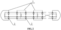
- Connectors 2 are symmetrically provided on end walls of the carriages 1 of the head car, the motor car and the intermediate car along a direction perpendicular to a direction of travel of the train, and each connector 2 on the end wall of the carriageis connected with other connectors on neighbouring carriages by means of wiring.
- the head car, the motor car and the intermediate car are connected to an electric wiring throughout an entirety of the train by means of the connectors 2 in any formation state.
- the train is provided with two parallel power supply wires running throughout the entirety of the train and multiple auxiliary power supply systems.
- An encoder is provided in the train, and the encoder is configured to encode a sequence number of a car and encode a type number of the car.
- the auxiliary power supply system an auxiliary converter 3, wherein the auxiliary converters 3 is set on all the cars, and on the basis of identifying the number and type of the carriage 1 by a train control and management system, the auxiliary converters 3 in the motor head car and the motor car are connected to the two parallel power supply wires.
- each of the connectors 2 includes: a coding wire interface and a power supply wire interface.
- One type of interface of each connector 2 is connected with a same type of interfaces of other connectors 2 by means of respective wires.
- the interfaces of the connectors 2 are axisymmetrically arranged on two sides of each of the end walls.
- a junction box is provided in the train, and connection wires of all connectors 2 are interconnected through wire sockets on the junction box.
- the encoder includes: four output ends for outputting the sequence number of the car and two output ends for outputting the type number of the car.
- relays are provided in the carriages 1 of the motor car and the intermediate car of the train; the relays are configured to control reversing when the car is reversed 180 degrees.
- the relays are connected to the auxiliary power supply system provided in the train.
- the auxiliary power supply system includes a car-mounted power box 4.
- the car-mounted power box 4 is connected with two power supply wires through a switching device provided in the car-mounted power box.
- a voltage introduced from outside the train is adjusted, by means of the auxiliary power supply system, to 50 Hz for use by devices in the train.
- the present disclosure further provides a power supply control method for the train.
- the method includes the following steps.
- Each carriage 1 is connected to a power supply wire according to a preset wire priority.
- the method further comprises: before each car is connected to the power supply wire according to the preset wire priority.
- a code of each carriage in a current arbitrarily-marshaled train is identified, and an auxiliary converter on a head car and a motor car is connected to two power supply wires, wherein the code of the carriage includes a sequence number of a car and a type number of the car.
- the connection of the current power supply wire is kept.
- the switching is automatic switching performed by means of a train control and management system or manual switching.
- the method before it is determined whether the current power supply wire connected malfunctions, the method includes: a state of a network of the train is determined, and if the state is good, the power supply of the train is controlled using the train control and management system.
- the power supply of the train is controlled manually.
- the technical solution of the present disclosure may ensure good connectivity of power supply wires in cases where a train is arbitrarily marshaled without being limited to the adjustment of car sequences or the reversal of cars.
- the solution may decrease the number of conversion devices in the EMU for converting between different voltage standards, thereby avoiding the electrical failure risk caused by using the single-phase inverter and reducing the costs of devices in the train.
- the solution realizes train formation a variable quantity of cars and arbitrary reversal of direction of an intermediate car, and may also ensure that when a single power supply wire malfunctions, emergency measures are taken timely to switch to another power supply wire without influence on auxiliary power supply of the train.
- the core concept of the solution lies in: a dual-redundancy design is applied to a power supply wire of a train running throughout the entirety of the train; an encoder and a relay for controlling reversal when the train is reversed 180 degrees are used to encode the train, so that a train control and management system may identify the number and type of the current car, and then control the train according to the information; and a power supply direction of the train is set through the relay, thereby assisting in setting a running direction of each train and assisting other subsystems, and finally realizing unlimited formation and power supply of the train.
- the present disclosure provides a train.
- the train at least includes two head cars and an intermediate car, and the head car is a motor head car.
- the head car is a motor head car.
- both the head car and the motor car may be motor type.
- the motor car and the intermediate car may be sequenced arbitrarily or reversed 180 degrees to form a free formation
- the connector 2 in order to ensure that all the wires of the train keep connected and performed correctly when the cars are sequenced arbitrarily or reversed 180 degrees to form the free formation, the connector 2 includes: a coding wire interface and a power supply wire interface.
- One type of interface of each connector 2 is connected with a same type of interfaces of other connectors 2 by means of respective wires.
- the interfaces on the left-side connector 2 and the interfaces on the right-side connector 2 on a same end wall are axisymmetrically arranged.
- the solution enables a train control and management system to learn the information about the number and type of the car connected.
- an encoder is set in each carriage 1, which is configured to encode a sequence number of the car and encode a type number of the car.
- the encoder is a six-digital encoder. Four output ends in the six-digital encoder are used for outputting the sequence number of the current car, and the other two output ends are used for outputting the type number of the current car.
- An output and display rule of the encoder adopts a binary mode. When the formation includes 16 cars, coding is as shown in the following table.
- the encoder of the train may be set manually, or automatically set by means of a program written and embedded in the train control and management system.
- a relay set in the carriage 1 in order to further realize the flexible formation after the car is reversed 180 degrees, there is a relay set in the carriage 1, and the relay is configured to control reversal when the train is reversed 180 degrees.
- the relay assists in setting the direction of travel of each car and changing power supply directions of other auxiliary systems.
- the auxiliary power supply system includes: an auxiliary converter 3 and a car-mounted power box 4.
- the auxiliary converter 3 is connected with two power supply wires.
- the car-mounted power box is connected with two power supply wires through a switching device provided in the car-mounted power box.
- a voltage introduced from outside the train is adjusted, by means of the auxiliary power supply system, to 50 Hz for use by devices in the train.
- the auxiliary converter 3 may be set on a carriage 1 where the powered device is placed or a carriage 1 which is the motor head car or the motor car.
- auxiliary converters 3 set on all the cars.
- the auxiliary converters 3 in the motor head car and the motor car are connected to two power supply wires.
- the embodiments of the present disclosure further provide a power supply control method for the train.
- the power supply control method may select the wiring of the carriage 1, and perform switching control on power supply according to the current state of the power supply wire and the network state of the train.
- the method includes the following specific steps.
- the train control and management system is used to identify the code of each carriage 1 in the current arbitrarily-marshaled train, and connect the auxiliary converter 3 on the head car and/or the motor car to two power supply wires. After the carriage 1 is incorporated in the whole train according to the required formation sequence, the code of the head car is fixed, and the train control and management system may be directly used to identify the code.
- the encoder is used to code the carriage 1, and the train control and management system identifies the code of the carriage 1 to determine its number and type. After the number and type of the carriage 1 are determined, functions such as power supply, baking and alarming of the carriage 1 may be managed and controlled.
- the train control and management system connects the car-mounted power box 4 of the carriage 1 to a power supply wire according to a preset wire priority of each carriage 1.
- the carriages 1 in all formations are connected to a same power supply wire, so that the train control and management system performs unified control conveniently.
- the connected wires of the carriages 1 may also be controlled separately under special circumstances.
- the train control and management system performs fault determination on the power supply wire that the carriage 1 is connected at present. If the currently connected power supply wire malfunctions, switch to another power supply wire; and if the current connected power supply wire does not malfunction, the current connected state of the power supply wire is kept. According to an embodiment of the disclosure, the switching is automatic switching performed by means of the train control and management system or manual switching.
- train control and management system also monitors the network state of the train; if the current network state of the train is good, the train control and management system is directly used to control the power supply of the train; and if the current network state of the train malfunctions, the power supply of the train is controlled manually.
- a high voltage is input in the auxiliary converter 3.
- a voltage DC 2800V is input in the auxiliary converter 3.
- a voltage AC 380V/50 Hz in a form of three-phase Four wire is output after inversion, filtering, voltage-drop and other processing are performed on the voltage DC 2800V.
- the auxiliary converter 3 has two capacities, namely 100 KVA and 230 KVA with a power factor of 0.85, which are respectively in the head cars (the cars 1 and 8, 100KVA turns out to be 85 KW) and the intermediate motor cars (the cars 2, 6 and 7, 230 KVA turns out to be 200 KW).
- the total capacity of the auxiliary converters 3 in the whole train is 890 KVA, and the power turns out to be 757 KW.
- Table 1 AC load calculation of variable formation Serial number MC M T AC load calculation Power Load Quantity Power Load Quantity Load Quantity Power of whole train Load of whole train 1 85 112 2 200 87 1 62 1 370 373 2 85 112 2 200 87 2 62 2 570 522 3 85 112 2 200 87 3 62 2 770 609 4 85 112 2 200 87 4 62 4 970 820 5 85 112 2 200 87 5 62 5 1170 969 6 85 112 2 200 87 6 62 8 1370 1242
- the maximum AC load of the motor head car namely the MC car
- the maximum AC load of the motor car namely the M car
- the maximum AC load of the intermediate car namely the T car
- the formation number may be adjusted arbitrarily according to the power and load of the auxiliary converter 3.
- the auxiliary converter 3 in each motor car forms a two three-phase four-wire bus-bars, namely the power supply wire 1 and the power supply wire 2, through an output contactor MK1, thereby realizing uninterrupted power supply to the three-phase bus-bars of the whole train.
- the train control and management system may directly control the output contactor MK1 to connect the auxiliary converter 3 to the power supply wire or disconnect the auxiliary converter 3 from the power supply wire.
- the output contactor MK1 may be controlled manually.
- the two three-phase AC bus-bars run in parallel to supply power for a three-phase load and a single-phase load through the contactor Q01 (which is closed during power supply through the power supply wire I) or the contactor Q02 (which is closed during power supply through the power supply wire II) in the car-mounted power box 4.
- the three-phase load adopts the U-phase power supply, the V-phase power supply and the W-phase power supply in the car-mounted power box 4 to provide the power supply of 3AC380V/50 Hz for a charger, a cooling fan, an air conditioner, an air compressor and other loads.
- the single-phase load adopts the power supply of each phase, namely the UN-phase power supply, the VN-phase power supply and the WN-phase power supply, in the car-mounted power box 4 to provide the power supply of AC220V/50 Hz for a sanding device, kitchen appliance, a socket and other loads.
- the on/off state of the switch in the car-mounted power box 4 may be controlled by the train control and management system, so as to implement selection of the power supply wire; furthermore, it is possible to manually select through a change-over switch to close the power supply contactor (Q01 or Q02) in the car-mounted power box 4, so as to implement selection of the power supply wire I or the power supply wire II.
- the redundancy connectors 2 Due to the setting of the redundancy connectors 2 on the end wall, arbitrary sequencing of cars and formation of cars reversed 180 degrees may be realized, and the number and type of the current carriage 1 are determined by receiving a signal from the train control and management system, so the connection of the dual-redundancy power supply wire when the train formation is variable may be satisfied, and the bus-bar required to provide power supply may be automatically selected according to the number of the current carriage 1. For example, in cases where the motor car No. 2 is in an original working condition, the power supply contactor Q01 is closed, and the power supply wire I is connected to provide supply power. When the motor car No.
- the state of the current car is determined by the train control and management system, the contactor Q02 is selected to be closed according to the connection priority of the power supply wire of the current carriage 1, and the power supply wire II is connected to provide supply power. If the power supply wire II that the motor car No. 2 is connected malfunctions, the power supply contactor Q01 is closed by the train control and management system or directly closed manually, the power supply contactor Q02 is disconnected, and the power supply wire I is connected to provide supply power.
- the whole AC load power supply system adopts two three-phase four-wire AC bus-bars running throughout the entirety of the train, so as to ensure the redundancy in power supply of the three-phase AC bus-bars and loads. Furthermore, controlling the contactor through an AC bus-bar change-over switch and the train control and management system satisfies the switching between the power supply wire I and the power supply wire II, thereby realizing train formation of a variable quantity of cars of EMU and arbitrary reversal of direction of an intermediate car.
- the solution may realize AC auxiliary power supply of the train based on the variable formation.
- An output voltage standard is 50 Hz, and a single-phase AC voltage 220V/50Hz may be formed with the wire N through each phase.
- One single-phase inverter of each car is reduced, that is to say, the technical risk caused by conversion between different voltage standards of the EMU is decreased and the cost of devices is reduced.
- the design of an auxiliary power supply control system of redundancy in power supply namely two three-phase four-wire AC bus-bars may realize the 180-degree reversal of any single car, which reduces the difficulty of operating and maintaining a formation operation.
- the formation of a variable quantity of cars in the whole train realizes the flexible formation according to a transport volume requirement.
Landscapes
- Engineering & Computer Science (AREA)
- Power Engineering (AREA)
- Mechanical Engineering (AREA)
- Transportation (AREA)
- Automation & Control Theory (AREA)
- Electric Propulsion And Braking For Vehicles (AREA)
Description
- The present disclosure relates to the technology of rail transit, in particular to a train and a power supply control method for a train.
- The current Electrical Multiple Unit (EMU) in our country is mainly of 8-car formation, and runs in a coupled running mode of 8-car formation, 16-car formation and two 8-car formations. However, the current formation mode of the EMU is fixed, that is to say, the position and direction of each car in a whole train are prescriptive when the car is designed, the formation type cannot be changed, and the number of cars included in the train cannot be changed too.
- In the process of designing a train, after an arrangement manner of cars is determined, the arrangement manner of each car cannot be changed during train formation at any time thereafter, that is to say, the positions of the first end and the second end of the car cannot be reversed during arrangement; if the sequence of each carriage is changed or the carriage is reversed 180 degrees, the car will be unable to be connected or will perform actions wrongly.
- As illustrated in
FIG. 1 , an auxiliary power supply system of the current EMU consists of an intermediate DC circuit of a traction converter, a single Auxiliary Converter Unit (ACU), a Double-Auxiliary Converter Unit (D-ACU), a charger, a battery, an assist and control electrical device, a ground power supply and on the like. The assist and control electrical device includes various AC and DC electrical devices. The single ACU is installed under a transformer car (TC07/TC02), and the D-ACU is installed under a first-class car (FC05) and a dining car (BC04). The charger and the battery are installed under the first-class car (FC05) and the dining car (BC04). In the figure, a medium voltage of3AC 440V output by the auxiliary converters of thecars DC 110V/230V 50 Hz) by means of a single-phase inverter of each car. It can be seen that a voltage system of medium-voltage bus-bar on the current EMU is 60 Hz, power supply through a car power socket needs to be converted independently, which not only increases an electrical failure risk caused by the single-phase inverter, but also increases the costs of train and devices. Power supply through one wire is adopted on the current EMU, thus the requirement of arbitrary train formation cannot be satisfied; furthermore, when a power supply wire malfunctions, there is not an effective emergency measure. - Related technologies are known from the document
CN103935246B . - To solve one of the above problems, the present disclosure provides a train, which includes a train formation including a head car, a motor car, and an intermediate car.
-
Connectors 2 are symmetrically provided on end walls of thecarriages 1 of the head car, the motor car and the intermediate car along a direction perpendicular to a direction of travel of the train, and eachconnector 2 on the end wall of the carriageis connected with other connectors on neighbouring carriages by means of wiring. - The head car, the motor car and the intermediate car are connected to an electric wiring throughout an entirety of the train by means of the
connectors 2 in any formation state. - The train is provided with two parallel power supply wires running throughout the entirety of the train and multiple auxiliary power supply systems.
- An encoder is provided in the train, and the encoder is configured to encode a sequence number of a car and encode a type number of the car.
- The auxiliary power supply system an
auxiliary converter 3, wherein theauxiliary converters 3 is set on all the cars, and on the basis of identifying the number and type of thecarriage 1 by a train control and management system, theauxiliary converters 3 in the motor head car and the motor car are connected to the two parallel power supply wires. - In some optional implementations, each of the
connectors 2 includes: a coding wire interface and a power supply wire interface. - One type of interface of each
connector 2 is connected with a same type of interfaces ofother connectors 2 by means of respective wires. - In some optional implementations, the interfaces of the
connectors 2 are axisymmetrically arranged on two sides of each of the end walls. - In some optional implementations, a junction box is provided in the train, and connection wires of all
connectors 2 are interconnected through wire sockets on the junction box. - In some optional implementations, the encoder includes: four output ends for outputting the sequence number of the car and two output ends for outputting the type number of the car.
- In some optional implementations, relays are provided in the
carriages 1 of the motor car and the intermediate car of the train; the relays are configured to control reversing when the car is reversed 180 degrees. - The relays are connected to the auxiliary power supply system provided in the train.
- In some optional implementations, the auxiliary power supply system includes a car-mounted
power box 4. - The car-mounted
power box 4 is connected with two power supply wires through a switching device provided in the car-mounted power box. - A voltage introduced from outside the train is adjusted, by means of the auxiliary power supply system, to 50 Hz for use by devices in the train.
- To solve one of the above technical problems, the present disclosure further provides a power supply control method for the train. The method includes the following steps.
- Each
carriage 1 is connected to a power supply wire according to a preset wire priority. - It is determined whether a current power supply wire connected malfunctions; and if the current power supply wire connected malfunctions, switching to another power supply wire is performed.
- The method further comprises: before each car is connected to the power supply wire according to the preset wire priority.
- a code of each carriage in a current arbitrarily-marshaled train is identified, and an auxiliary converter on a head car and a motor car is connected to two power supply wires, wherein the code of the carriage includes a sequence number of a car and a type number of the car.
- In some optional implementations, if the current power supply wire connected does not malfunction, the connection of the current power supply wire is kept.
- In some optional implementations, the switching is automatic switching performed by means of a train control and management system or manual switching.
- In some optional implementations, before it is determined whether the current power supply wire connected malfunctions, the method includes:
a state of a network of the train is determined, and if the state is good, the power supply of the train is controlled using the train control and management system. - In some optional implementations, if the network of the train malfunctions, the power supply of the train is controlled manually.
- The beneficial effects of the present disclosure are as follows.
- The technical solution of the present disclosure may ensure good connectivity of power supply wires in cases where a train is arbitrarily marshaled without being limited to the adjustment of car sequences or the reversal of cars. The solution may decrease the number of conversion devices in the EMU for converting between different voltage standards, thereby avoiding the electrical failure risk caused by using the single-phase inverter and reducing the costs of devices in the train. By designing an auxiliary power supply system topology having redundant power supply, the solution realizes train formation a variable quantity of cars and arbitrary reversal of direction of an intermediate car, and may also ensure that when a single power supply wire malfunctions, emergency measures are taken timely to switch to another power supply wire without influence on auxiliary power supply of the train.
- The accompanying drawings described here are used for providing further understanding of the present disclosure, and constitute a part of the present disclosure. Schematic embodiments of the present disclosure and description thereof are used for illustrating the present disclosure and not intended to form an improper limit to the present disclosure. In the accompanying drawings:
-
FIG. 1 is a schematic diagram of a power supply system of a train in the conventional art. -
FIG. 2 is a schematic diagram of an auxiliary power supply system of a variable formation according to an embodiment of the present disclosure. -
FIG. 3 is a schematic diagram of wire connection of a connector on an end wall of each carriage according to an embodiment of the present disclosure. -
FIG. 4 is a schematic diagram of a train formation according to an embodiment of the present disclosure. -
FIG. 5 is a schematic diagram of a power supply control method for a train according to an embodiment of the present disclosure. - 1. carriage; 2. connector; 3. auxiliary converter; 4. car-mounted power box.
- In order to make the technical solutions and advantages in embodiments of the present disclosure clearer, the exemplary embodiments in the present disclosure are further elaborated below in combination with the accompanying drawings. It is apparent that the described embodiments are only a part of the embodiments of the present disclosure but not all. It is to be noted that the embodiments in the present disclosure and the characteristics in the embodiments may be combined under the condition of no conflicts.
- The core concept of the solution lies in: a dual-redundancy design is applied to a power supply wire of a train running throughout the entirety of the train; an encoder and a relay for controlling reversal when the train is reversed 180 degrees are used to encode the train, so that a train control and management system may identify the number and type of the current car, and then control the train according to the information; and a power supply direction of the train is set through the relay, thereby assisting in setting a running direction of each train and assisting other subsystems, and finally realizing unlimited formation and power supply of the train.
- Specifically, the present disclosure provides a train. The train at least includes two head cars and an intermediate car, and the head car is a motor head car. When the train includes a head car, a motor car and an intermediate car, both the head car and the motor car may be motor type. In order to satisfy that the motor car and the intermediate car may be sequenced arbitrarily or reversed 180 degrees to form a free formation, there are
connectors 2 symmetrically provided on end walls ofcarriages 1 of the head car, the motor car and the intermediate car along a direction perpendicular to a direction of travel of the train, and allconnectors 2 on the end walls of the train are connected by means of wiring; at this point, the head car, the motor car and the intermediate car may be connected to an electric wiring throughout an entirety of the train by means of theconnectors 2 in any formation state. There are two parallel power supply wires running throughout the entirety of the train and a plurality of auxiliary power supply systems provided on the train. - According to an embodiment of the disclosure, in order to ensure that all the wires of the train keep connected and performed correctly when the cars are sequenced arbitrarily or reversed 180 degrees to form the free formation, the
connector 2 includes: a coding wire interface and a power supply wire interface. One type of interface of eachconnector 2 is connected with a same type of interfaces ofother connectors 2 by means of respective wires. As illustrated inFIG. 2 , in order to satisfy that any car of the train can be inserted in the formation and the car can be reversed 180 degrees in the formation, the interfaces on the left-side connector 2 and the interfaces on the right-side connector 2 on a same end wall are axisymmetrically arranged. - In order to realize a flexible train formation, the solution enables a train control and management system to learn the information about the number and type of the car connected. To do so, an encoder is set in each
carriage 1, which is configured to encode a sequence number of the car and encode a type number of the car. In some optional implementations, in the solution, the encoder is a six-digital encoder. Four output ends in the six-digital encoder are used for outputting the sequence number of the current car, and the other two output ends are used for outputting the type number of the current car. An output and display rule of the encoder adopts a binary mode. When the formation includes 16 cars, coding is as shown in the following table.Table 1 Coding Table of Train B0 B1 B2 B3 Sequence 0 0 0 1 1 0 0 1 0 2 0 0 1 1 3 0 1 0 0 4 0 1 0 1 5 0 1 1 0 6 0 1 1 1 7 1 0 0 0 8 1 0 0 1 9 1 0 1 0 10 1 0 1 1 11 1 1 0 0 12 1 1 0 1 13 1 1 1 0 14 1 1 1 1 15 0 0 0 0 16 - There are two types of cars, namely a motor car or a trailer car. When a code output of the motor car is 01, the code output of the trailer car is 10. The code outputs represent the current type of the car. The encoder of the train may be set manually, or automatically set by means of a program written and embedded in the train control and management system.
- According to an embodiment of the disclosure, in order to further realize the flexible formation after the car is reversed 180 degrees, there is a relay set in the
carriage 1, and the relay is configured to control reversal when the train is reversed 180 degrees. The relay assists in setting the direction of travel of each car and changing power supply directions of other auxiliary systems. - As illustrated in
FIG. 3 , according to an embodiment not being part of the invention, the auxiliary power supply system includes: anauxiliary converter 3 and a car-mountedpower box 4. Theauxiliary converter 3 is connected with two power supply wires. The car-mounted power box is connected with two power supply wires through a switching device provided in the car-mounted power box. A voltage introduced from outside the train is adjusted, by means of the auxiliary power supply system, to 50 Hz for use by devices in the train. In the present embodiment not being part of the invention, according to a position where a powered device of the train is placed and the determined type of thecarriage 1, theauxiliary converter 3 may be set on acarriage 1 where the powered device is placed or acarriage 1 which is the motor head car or the motor car. In another embodiment, there are theauxiliary converters 3 set on all the cars. On the basis of identifying the number and type of thecarriage 1 by the train control and management system, theauxiliary converters 3 in the motor head car and the motor car are connected to two power supply wires. - The embodiments of the present disclosure further provide a power supply control method for the train. The power supply control method may select the wiring of the
carriage 1, and perform switching control on power supply according to the current state of the power supply wire and the network state of the train. The method includes the following specific steps. - The train control and management system is used to identify the code of each
carriage 1 in the current arbitrarily-marshaled train, and connect theauxiliary converter 3 on the head car and/or the motor car to two power supply wires. After thecarriage 1 is incorporated in the whole train according to the required formation sequence, the code of the head car is fixed, and the train control and management system may be directly used to identify the code. For theintermediate carriage 1, the encoder is used to code thecarriage 1, and the train control and management system identifies the code of thecarriage 1 to determine its number and type. After the number and type of thecarriage 1 are determined, functions such as power supply, baking and alarming of thecarriage 1 may be managed and controlled. - After the specific code and type of the
carriage 1 are determined, the train control and management system connects the car-mountedpower box 4 of thecarriage 1 to a power supply wire according to a preset wire priority of eachcarriage 1. Preferably, thecarriages 1 in all formations are connected to a same power supply wire, so that the train control and management system performs unified control conveniently. The connected wires of thecarriages 1 may also be controlled separately under special circumstances. - The train control and management system performs fault determination on the power supply wire that the
carriage 1 is connected at present. If the currently connected power supply wire malfunctions, switch to another power supply wire; and if the current connected power supply wire does not malfunction, the current connected state of the power supply wire is kept. According to an embodiment of the disclosure, the switching is automatic switching performed by means of the train control and management system or manual switching. - According to an embodiment of the disclosure, train control and management system also monitors the network state of the train; if the current network state of the train is good, the train control and management system is directly used to control the power supply of the train; and if the current network state of the train malfunctions, the power supply of the train is controlled manually.
- The solution is further elaborated through a group of examples.
- According to an embodiment of the disclosure, a high voltage is input in the
auxiliary converter 3. In the present embodiment, a voltage DC 2800V is input in theauxiliary converter 3. Avoltage AC 380V/50 Hz in a form of three-phase Four wire is output after inversion, filtering, voltage-drop and other processing are performed on the voltage DC 2800V. In the embodiment, as illustrated inFIG. 3 , theauxiliary converter 3 has two capacities, namely 100 KVA and 230 KVA with a power factor of 0.85, which are respectively in the head cars (thecars cars 2, 6 and 7, 230 KVA turns out to be 200 KW). The total capacity of theauxiliary converters 3 in the whole train is 890 KVA, and the power turns out to be 757 KW.Table 1 AC load calculation of variable formation Serial number MC M T AC load calculation Power Load Quantity Power Load Quantity Load Quantity Power of whole train Load of whole train 1 85 112 2 200 87 1 62 1 370 373 2 85 112 2 200 87 2 62 2 570 522 3 85 112 2 200 87 3 62 2 770 609 4 85 112 2 200 87 4 62 4 970 820 5 85 112 2 200 87 5 62 5 1170 969 6 85 112 2 200 87 6 62 8 1370 1242 - According to statistical calculation of a load power, the maximum AC load of the motor head car, namely the MC car, is 112 KW; the maximum AC load of the motor car, namely the M car, is 87 KW; and the maximum AC load of the intermediate car, namely the T car, is 62 KW. Thus, the formation number may be adjusted arbitrarily according to the power and load of the
auxiliary converter 3. - As illustrated in
FIG. 3 , theauxiliary converter 3 in each motor car forms a two three-phase four-wire bus-bars, namely thepower supply wire 1 and thepower supply wire 2, through an output contactor MK1, thereby realizing uninterrupted power supply to the three-phase bus-bars of the whole train. When the network state is good, the train control and management system may directly control the output contactor MK1 to connect theauxiliary converter 3 to the power supply wire or disconnect theauxiliary converter 3 from the power supply wire. When the network malfunctions, the output contactor MK1 may be controlled manually. The two three-phase AC bus-bars run in parallel to supply power for a three-phase load and a single-phase load through the contactor Q01 (which is closed during power supply through the power supply wire I) or the contactor Q02 (which is closed during power supply through the power supply wire II) in the car-mountedpower box 4. - As illustrated in
FIG. 3 , the three-phase load adopts the U-phase power supply, the V-phase power supply and the W-phase power supply in the car-mountedpower box 4 to provide the power supply of 3AC380V/50 Hz for a charger, a cooling fan, an air conditioner, an air compressor and other loads. - The single-phase load adopts the power supply of each phase, namely the UN-phase power supply, the VN-phase power supply and the WN-phase power supply, in the car-mounted
power box 4 to provide the power supply of AC220V/50 Hz for a sanding device, kitchen appliance, a socket and other loads. - When a switch set in the car-mounted
power box 4 of eachcarriage 1 is at an automatic position, the on/off state of the switch in the car-mountedpower box 4 may be controlled by the train control and management system, so as to implement selection of the power supply wire; furthermore, it is possible to manually select through a change-over switch to close the power supply contactor (Q01 or Q02) in the car-mountedpower box 4, so as to implement selection of the power supply wire I or the power supply wire II. - Due to the setting of the
redundancy connectors 2 on the end wall, arbitrary sequencing of cars and formation of cars reversed 180 degrees may be realized, and the number and type of thecurrent carriage 1 are determined by receiving a signal from the train control and management system, so the connection of the dual-redundancy power supply wire when the train formation is variable may be satisfied, and the bus-bar required to provide power supply may be automatically selected according to the number of thecurrent carriage 1. For example, in cases where the motor car No. 2 is in an original working condition, the power supply contactor Q01 is closed, and the power supply wire I is connected to provide supply power. When the motor car No. 2 is reversed 180 degrees, the state of the current car is determined by the train control and management system, the contactor Q02 is selected to be closed according to the connection priority of the power supply wire of thecurrent carriage 1, and the power supply wire II is connected to provide supply power. If the power supply wire II that the motor car No. 2 is connected malfunctions, the power supply contactor Q01 is closed by the train control and management system or directly closed manually, the power supply contactor Q02 is disconnected, and the power supply wire I is connected to provide supply power. - The whole AC load power supply system adopts two three-phase four-wire AC bus-bars running throughout the entirety of the train, so as to ensure the redundancy in power supply of the three-phase AC bus-bars and loads. Furthermore, controlling the contactor through an AC bus-bar change-over switch and the train control and management system satisfies the switching between the power supply wire I and the power supply wire II, thereby realizing train formation of a variable quantity of cars of EMU and arbitrary reversal of direction of an intermediate car.
- The solution may realize AC auxiliary power supply of the train based on the variable formation. An output voltage standard is 50 Hz, and a single-phase AC voltage 220V/50Hz may be formed with the wire N through each phase. One single-phase inverter of each car is reduced, that is to say, the technical risk caused by conversion between different voltage standards of the EMU is decreased and the cost of devices is reduced. Moreover, the design of an auxiliary power supply control system of redundancy in power supply, namely two three-phase four-wire AC bus-bars may realize the 180-degree reversal of any single car, which reduces the difficulty of operating and maintaining a formation operation. The formation of a variable quantity of cars in the whole train realizes the flexible formation according to a transport volume requirement.
Claims (12)
- A train, comprising: a train formation including a head car, a motor car and an intermediate car,wherein connectors (2) are symmetrically provided on end walls of carriages (1) of the head car, the motor car and the intermediate car along a direction perpendicular to a direction of travel of the train, and each connector (2) on the end wall of the carriage is connected with other connectors on neighbouring carriages by means of wiring;the head car, the motor car and the intermediate car are connected to an electric wiring throughout an entirety of the train by means of the connectors (2) in any formation state; andthe train is provided with two parallel power supply wires running throughout the entirety of the train and a plurality of auxiliary power supply systems,wherein an encoder is provided in the train, and the encoder is configured to encode a sequence number of a car and encode a type number of the car,characterized in that: the auxiliary power supply system comprises an auxiliary converter (3), wherein the auxiliary converters (3) is set on all the cars, and on the basis of identifying the number and type of the carriage (1) by a train control and management system, the auxiliary converters (3) in the motor head car and the motor car are connected to the two parallel power supply wires.
- The train of claim 1, wherein each of the connectors (2) comprises: a coding wire interface and a power supply wire interface;
one type of interface of each connector (2) is connected with a same type of interfaces of other connectors (2) by means of respective wires. - The train of claim 2, wherein the interfaces of the connectors (2) are axisymmetrically arranged on two sides of each of the end walls.
- The train of claim 3, wherein a junction box is provided in the train, and connection wires of all connectors (2) are interconnected through wire sockets on the junction box.
- The train of claim 1, wherein the encoder comprises: four output ends for outputting the sequence number of the car and two output ends for outputting the type number of the car.
- The train of claim 1, wherein relays are provided in the carriages (1) of the motor car and the intermediate car of the train; the relays are configured to control reversing when the car is reversed 180 degrees;
the relays are connected to the auxiliary power supply system provided in the train. - The train of claim 1, wherein the auxiliary power supply system comprises a car-mounted power box (4);the car-mounted power box (4) is connected with two power supply wires through a switching device provided in the car-mounted power box (4);a voltage introduced from outside the train is adjusted, by means of the auxiliary power supply system, to 50 Hz for use by devices in the train.
- A power supply control method for a train of any one of claims 1 to 7, the method comprising:connecting each carriage to a power supply wire according to a preset wire priority (S1);determining whether a current power supply wire connected malfunctions, and if the current power supply wire connected malfunctions, switching to another power supply wire (S2),characterized in that: the method further comprises: before connecting each car to the power supply wire according to the preset wire priority,identifying a code of each carriage in a current arbitrarily-marshaled train, and connecting an auxiliary converter on a head car and a motor car to two power supply wires, wherein the code of the carriage comprises a sequence number of a car and a type number of the car.
- The power supply control method of claim 8, wherein if the current power supply wire connected does not malfunction, keeping the connection of the current power supply wire.
- The power supply control method of any one of claims 8 to 9, wherein the switching is automatic switching performed by means of a train control and management system or manual switching.
- The power supply control method of any one of claims 8 to 9, further comprising: before determining whether the current power supply wire connected malfunctions,
determining a state of a network of the train, and if the state is good, controlling power supply of the train using the train control and management system. - The power supply control method of claim 11, wherein if the network of the train malfunctions, controlling manually the power supply of the train.
Applications Claiming Priority (2)
| Application Number | Priority Date | Filing Date | Title |
|---|---|---|---|
| CN201711164097.XA CN109808617B (en) | 2017-11-21 | 2017-11-21 | Train and train power supply control method |
| PCT/CN2018/093650 WO2019100720A1 (en) | 2017-11-21 | 2018-06-29 | Train and train power supply control method |
Publications (3)
| Publication Number | Publication Date |
|---|---|
| EP3628561A1 EP3628561A1 (en) | 2020-04-01 |
| EP3628561A4 EP3628561A4 (en) | 2020-12-02 |
| EP3628561B1 true EP3628561B1 (en) | 2022-08-31 |
Family
ID=66599697
Family Applications (1)
| Application Number | Title | Priority Date | Filing Date |
|---|---|---|---|
| EP18880760.6A Active EP3628561B1 (en) | 2017-11-21 | 2018-06-29 | Train and train power supply control method |
Country Status (5)
| Country | Link |
|---|---|
| US (1) | US11535104B2 (en) |
| EP (1) | EP3628561B1 (en) |
| CN (1) | CN109808617B (en) |
| PT (1) | PT3628561T (en) |
| WO (1) | WO2019100720A1 (en) |
Families Citing this family (8)
| Publication number | Priority date | Publication date | Assignee | Title |
|---|---|---|---|---|
| US11511780B2 (en) * | 2017-11-21 | 2022-11-29 | Crrc Tangshan Co., Ltd. | Carriage, head carriage, middle carriage, and train |
| CN110806505B (en) * | 2019-12-03 | 2024-12-06 | 通号(西安)轨道交通工业集团有限公司北京分公司 | A signal output control device |
| CN112319317B (en) * | 2020-10-30 | 2022-04-15 | 中车大连电力牵引研发中心有限公司 | Topological structure of high-voltage system of air rail vehicle |
| CN112277985B (en) * | 2020-11-03 | 2021-11-09 | 中车青岛四方机车车辆股份有限公司 | Air conditioner load control system, air conditioner load shedding control method and device and motor train unit |
| CN115891757B (en) * | 2021-09-30 | 2024-09-10 | 比亚迪股份有限公司 | Vehicle power change control method and system and vehicle |
| CN114919604B (en) * | 2022-06-02 | 2024-07-09 | 北京轨道交通技术装备集团有限公司 | Rail vehicle grouping, rail vehicle reconnection grouping and rail system |
| CN116691740B (en) * | 2023-06-02 | 2025-11-14 | 中车青岛四方车辆研究所有限公司 | Intelligent power supply system, method, electronic equipment and storage medium for high-speed trains |
| CN118472900A (en) * | 2024-05-09 | 2024-08-09 | 中车长春轨道客车股份有限公司 | Medium-voltage power supply system, fault positioning method of medium-voltage power supply system and motor train unit |
Family Cites Families (16)
| Publication number | Priority date | Publication date | Assignee | Title |
|---|---|---|---|---|
| US2563571A (en) | 1951-08-07 | woods | ||
| DE4441396C1 (en) * | 1994-11-09 | 1996-02-22 | Siemens Ag | Goods train signal transmission coupling system |
| JP3078797B1 (en) | 1999-06-04 | 2000-08-21 | 川崎重工業株式会社 | Switchgear for coupler cover |
| RU2445223C1 (en) * | 2007-11-30 | 2012-03-20 | Мицубиси Электрик Корпорейшн | System and device for identification of railway train configuration |
| JP4685902B2 (en) * | 2008-05-28 | 2011-05-18 | 株式会社日立製作所 | Railway vehicle system |
| DE102010035302C5 (en) | 2010-08-16 | 2015-04-23 | Alstom Transport Technologies | Method and device for monitoring an operating state of a coupling device |
| JP5801999B2 (en) * | 2010-08-24 | 2015-10-28 | 株式会社日立製作所 | Train trains equipped with railway on-board electrical equipment |
| WO2012174382A1 (en) | 2011-06-17 | 2012-12-20 | General Electric Company | System and method for communicating data in a passenger vehicle or other vehicle consist |
| EP2605395A1 (en) * | 2011-12-13 | 2013-06-19 | Bombardier Transportation GmbH | A track-bound vehicle inverter |
| CN103318193B (en) | 2013-06-29 | 2015-12-16 | 南车南京浦镇车辆有限公司 | Motor train unit many Electrics reconnection control circuit and heavy linked method |
| CN103935246B (en) * | 2014-02-28 | 2015-12-02 | 青岛四方车辆研究所有限公司 | Motor train unit auxiliary power supply system and fault off-load method |
| CN203697972U (en) | 2014-02-28 | 2014-07-09 | 青岛四方车辆研究所有限公司 | Auxiliary power supply system of motor train unit |
| CN104554300B (en) | 2014-11-27 | 2017-06-23 | 中车青岛四方机车车辆股份有限公司 | It is a kind of to realize the change-over circuit that train arbitrary end joins again |
| CN105059310B (en) | 2015-08-10 | 2017-10-03 | 中车青岛四方机车车辆股份有限公司 | A kind of control system and control method for realizing that car arbitrarily joins again end to end |
| CN105438222A (en) * | 2015-12-01 | 2016-03-30 | 唐山轨道客车有限责任公司 | Train formation control system |
| US9796396B2 (en) * | 2016-02-18 | 2017-10-24 | Electro-Motive Diesel, Inc. | Train control system having remote configuration interface |
-
2017
- 2017-11-21 CN CN201711164097.XA patent/CN109808617B/en active Active
-
2018
- 2018-06-29 WO PCT/CN2018/093650 patent/WO2019100720A1/en not_active Ceased
- 2018-06-29 PT PT188807606T patent/PT3628561T/en unknown
- 2018-06-29 EP EP18880760.6A patent/EP3628561B1/en active Active
- 2018-06-29 US US16/627,323 patent/US11535104B2/en active Active
Also Published As
| Publication number | Publication date |
|---|---|
| WO2019100720A1 (en) | 2019-05-31 |
| US20210155095A1 (en) | 2021-05-27 |
| CN109808617B (en) | 2022-03-18 |
| EP3628561A4 (en) | 2020-12-02 |
| PT3628561T (en) | 2022-11-08 |
| EP3628561A1 (en) | 2020-04-01 |
| US11535104B2 (en) | 2022-12-27 |
| CN109808617A (en) | 2019-05-28 |
Similar Documents
| Publication | Publication Date | Title |
|---|---|---|
| US11535104B2 (en) | Train and train power supply control method | |
| CN103935246B (en) | Motor train unit auxiliary power supply system and fault off-load method | |
| CN109149625B (en) | Auxiliary inverter grid-connected system and method for subway vehicle | |
| CN102431469B (en) | Motor train unit subsidiary loop split-phase passing uninterruptible power supply device | |
| CN111969585B (en) | Traction substation power supply system with three-way power supply | |
| CN102170169A (en) | Power-supply system of vehicle-mounted auxiliary inverter power source | |
| AU2013231166B2 (en) | Systems and methods for distributing power in a vehicle | |
| CN202320318U (en) | Train power supply system | |
| EP3632770A1 (en) | Carriage, head carriage, middle carriage, and train | |
| CN203697972U (en) | Auxiliary power supply system of motor train unit | |
| CN106541828B (en) | Rail traffic vehicles AC power supply system redundant power supply circuit, vehicle and method | |
| CN205202756U (en) | Locomotive traction system | |
| CN202016401U (en) | Circuit structure unit for auxiliary system of magnetic suspension train | |
| CN108944578B (en) | Power supply device and power supply method for train and train | |
| CN111572414B (en) | Multi-power-supply-system power supply system and power supply method | |
| CN109687483B (en) | Electrified railway in-phase power supply system based on SCOTT wiring | |
| CN219801557U (en) | Van-type vehicle and multi-machine parallel operation grid-connection system thereof | |
| CN113452010B (en) | Rail transit power supply system and control method for rail transit power supply system | |
| CN205319966U (en) | Vehicle auxiliary electrical power source power supply system | |
| CN206217884U (en) | A kind of controller control box | |
| CN205911811U (en) | A multi-channel intelligent maintenance auxiliary power supply system for EMUs | |
| CN107769363A (en) | The apparatus and method that forced oil-circulation air-cooled transformer cooler is thrown by force | |
| CN213705185U (en) | A control circuit and system for extending power supply | |
| CN212572454U (en) | Frequency converter switching circuit | |
| CN207530608U (en) | The device that forced oil-circulation air-cooled transformer cooler is thrown by force |
Legal Events
| Date | Code | Title | Description |
|---|---|---|---|
| STAA | Information on the status of an ep patent application or granted ep patent |
Free format text: STATUS: THE INTERNATIONAL PUBLICATION HAS BEEN MADE |
|
| PUAI | Public reference made under article 153(3) epc to a published international application that has entered the european phase |
Free format text: ORIGINAL CODE: 0009012 |
|
| STAA | Information on the status of an ep patent application or granted ep patent |
Free format text: STATUS: REQUEST FOR EXAMINATION WAS MADE |
|
| 17P | Request for examination filed |
Effective date: 20191226 |
|
| AK | Designated contracting states |
Kind code of ref document: A1 Designated state(s): AL AT BE BG CH CY CZ DE DK EE ES FI FR GB GR HR HU IE IS IT LI LT LU LV MC MK MT NL NO PL PT RO RS SE SI SK SM TR |
|
| AX | Request for extension of the european patent |
Extension state: BA ME |
|
| A4 | Supplementary search report drawn up and despatched |
Effective date: 20201103 |
|
| RIC1 | Information provided on ipc code assigned before grant |
Ipc: B61C 17/00 20060101AFI20201028BHEP Ipc: B61G 5/10 20060101ALI20201028BHEP Ipc: B60L 15/32 20060101ALI20201028BHEP |
|
| DAV | Request for validation of the european patent (deleted) | ||
| DAX | Request for extension of the european patent (deleted) | ||
| STAA | Information on the status of an ep patent application or granted ep patent |
Free format text: STATUS: EXAMINATION IS IN PROGRESS |
|
| 17Q | First examination report despatched |
Effective date: 20211015 |
|
| REG | Reference to a national code |
Ref country code: DE Ref legal event code: R079 Ref document number: 602018040168 Country of ref document: DE Free format text: PREVIOUS MAIN CLASS: B61C0007000000 Ipc: B61C0017000000 |
|
| GRAP | Despatch of communication of intention to grant a patent |
Free format text: ORIGINAL CODE: EPIDOSNIGR1 |
|
| STAA | Information on the status of an ep patent application or granted ep patent |
Free format text: STATUS: GRANT OF PATENT IS INTENDED |
|
| RIC1 | Information provided on ipc code assigned before grant |
Ipc: B60L 1/00 20060101ALI20220404BHEP Ipc: B61G 5/10 20060101ALI20220404BHEP Ipc: B60L 15/32 20060101ALI20220404BHEP Ipc: B61C 17/00 20060101AFI20220404BHEP |
|
| INTG | Intention to grant announced |
Effective date: 20220502 |
|
| GRAS | Grant fee paid |
Free format text: ORIGINAL CODE: EPIDOSNIGR3 |
|
| GRAA | (expected) grant |
Free format text: ORIGINAL CODE: 0009210 |
|
| STAA | Information on the status of an ep patent application or granted ep patent |
Free format text: STATUS: THE PATENT HAS BEEN GRANTED |
|
| AK | Designated contracting states |
Kind code of ref document: B1 Designated state(s): AL AT BE BG CH CY CZ DE DK EE ES FI FR GB GR HR HU IE IS IT LI LT LU LV MC MK MT NL NO PL PT RO RS SE SI SK SM TR |
|
| REG | Reference to a national code |
Ref country code: CH Ref legal event code: EP Ref country code: GB Ref legal event code: FG4D |
|
| REG | Reference to a national code |
Ref country code: AT Ref legal event code: REF Ref document number: 1515095 Country of ref document: AT Kind code of ref document: T Effective date: 20220915 |
|
| REG | Reference to a national code |
Ref country code: DE Ref legal event code: R096 Ref document number: 602018040168 Country of ref document: DE |
|
| REG | Reference to a national code |
Ref country code: IE Ref legal event code: FG4D |
|
| REG | Reference to a national code |
Ref country code: PT Ref legal event code: SC4A Ref document number: 3628561 Country of ref document: PT Date of ref document: 20221108 Kind code of ref document: T Free format text: AVAILABILITY OF NATIONAL TRANSLATION Effective date: 20221031 |
|
| REG | Reference to a national code |
Ref country code: LT Ref legal event code: MG9D |
|
| REG | Reference to a national code |
Ref country code: NL Ref legal event code: MP Effective date: 20220831 |
|
| PG25 | Lapsed in a contracting state [announced via postgrant information from national office to epo] |
Ref country code: SE Free format text: LAPSE BECAUSE OF FAILURE TO SUBMIT A TRANSLATION OF THE DESCRIPTION OR TO PAY THE FEE WITHIN THE PRESCRIBED TIME-LIMIT Effective date: 20220831 Ref country code: RS Free format text: LAPSE BECAUSE OF FAILURE TO SUBMIT A TRANSLATION OF THE DESCRIPTION OR TO PAY THE FEE WITHIN THE PRESCRIBED TIME-LIMIT Effective date: 20220831 Ref country code: NO Free format text: LAPSE BECAUSE OF FAILURE TO SUBMIT A TRANSLATION OF THE DESCRIPTION OR TO PAY THE FEE WITHIN THE PRESCRIBED TIME-LIMIT Effective date: 20221130 Ref country code: LV Free format text: LAPSE BECAUSE OF FAILURE TO SUBMIT A TRANSLATION OF THE DESCRIPTION OR TO PAY THE FEE WITHIN THE PRESCRIBED TIME-LIMIT Effective date: 20220831 Ref country code: LT Free format text: LAPSE BECAUSE OF FAILURE TO SUBMIT A TRANSLATION OF THE DESCRIPTION OR TO PAY THE FEE WITHIN THE PRESCRIBED TIME-LIMIT Effective date: 20220831 Ref country code: FI Free format text: LAPSE BECAUSE OF FAILURE TO SUBMIT A TRANSLATION OF THE DESCRIPTION OR TO PAY THE FEE WITHIN THE PRESCRIBED TIME-LIMIT Effective date: 20220831 |
|
| REG | Reference to a national code |
Ref country code: AT Ref legal event code: MK05 Ref document number: 1515095 Country of ref document: AT Kind code of ref document: T Effective date: 20220831 |
|
| PG25 | Lapsed in a contracting state [announced via postgrant information from national office to epo] |
Ref country code: PL Free format text: LAPSE BECAUSE OF FAILURE TO SUBMIT A TRANSLATION OF THE DESCRIPTION OR TO PAY THE FEE WITHIN THE PRESCRIBED TIME-LIMIT Effective date: 20220831 Ref country code: IS Free format text: LAPSE BECAUSE OF FAILURE TO SUBMIT A TRANSLATION OF THE DESCRIPTION OR TO PAY THE FEE WITHIN THE PRESCRIBED TIME-LIMIT Effective date: 20221231 Ref country code: HR Free format text: LAPSE BECAUSE OF FAILURE TO SUBMIT A TRANSLATION OF THE DESCRIPTION OR TO PAY THE FEE WITHIN THE PRESCRIBED TIME-LIMIT Effective date: 20220831 Ref country code: GR Free format text: LAPSE BECAUSE OF FAILURE TO SUBMIT A TRANSLATION OF THE DESCRIPTION OR TO PAY THE FEE WITHIN THE PRESCRIBED TIME-LIMIT Effective date: 20221201 |
|
| PG25 | Lapsed in a contracting state [announced via postgrant information from national office to epo] |
Ref country code: SM Free format text: LAPSE BECAUSE OF FAILURE TO SUBMIT A TRANSLATION OF THE DESCRIPTION OR TO PAY THE FEE WITHIN THE PRESCRIBED TIME-LIMIT Effective date: 20220831 Ref country code: RO Free format text: LAPSE BECAUSE OF FAILURE TO SUBMIT A TRANSLATION OF THE DESCRIPTION OR TO PAY THE FEE WITHIN THE PRESCRIBED TIME-LIMIT Effective date: 20220831 Ref country code: ES Free format text: LAPSE BECAUSE OF FAILURE TO SUBMIT A TRANSLATION OF THE DESCRIPTION OR TO PAY THE FEE WITHIN THE PRESCRIBED TIME-LIMIT Effective date: 20220831 Ref country code: DK Free format text: LAPSE BECAUSE OF FAILURE TO SUBMIT A TRANSLATION OF THE DESCRIPTION OR TO PAY THE FEE WITHIN THE PRESCRIBED TIME-LIMIT Effective date: 20220831 Ref country code: CZ Free format text: LAPSE BECAUSE OF FAILURE TO SUBMIT A TRANSLATION OF THE DESCRIPTION OR TO PAY THE FEE WITHIN THE PRESCRIBED TIME-LIMIT Effective date: 20220831 Ref country code: AT Free format text: LAPSE BECAUSE OF FAILURE TO SUBMIT A TRANSLATION OF THE DESCRIPTION OR TO PAY THE FEE WITHIN THE PRESCRIBED TIME-LIMIT Effective date: 20220831 |
|
| PG25 | Lapsed in a contracting state [announced via postgrant information from national office to epo] |
Ref country code: SK Free format text: LAPSE BECAUSE OF FAILURE TO SUBMIT A TRANSLATION OF THE DESCRIPTION OR TO PAY THE FEE WITHIN THE PRESCRIBED TIME-LIMIT Effective date: 20220831 Ref country code: EE Free format text: LAPSE BECAUSE OF FAILURE TO SUBMIT A TRANSLATION OF THE DESCRIPTION OR TO PAY THE FEE WITHIN THE PRESCRIBED TIME-LIMIT Effective date: 20220831 |
|
| REG | Reference to a national code |
Ref country code: DE Ref legal event code: R097 Ref document number: 602018040168 Country of ref document: DE |
|
| PG25 | Lapsed in a contracting state [announced via postgrant information from national office to epo] |
Ref country code: NL Free format text: LAPSE BECAUSE OF FAILURE TO SUBMIT A TRANSLATION OF THE DESCRIPTION OR TO PAY THE FEE WITHIN THE PRESCRIBED TIME-LIMIT Effective date: 20220831 Ref country code: AL Free format text: LAPSE BECAUSE OF FAILURE TO SUBMIT A TRANSLATION OF THE DESCRIPTION OR TO PAY THE FEE WITHIN THE PRESCRIBED TIME-LIMIT Effective date: 20220831 |
|
| PLBE | No opposition filed within time limit |
Free format text: ORIGINAL CODE: 0009261 |
|
| STAA | Information on the status of an ep patent application or granted ep patent |
Free format text: STATUS: NO OPPOSITION FILED WITHIN TIME LIMIT |
|
| 26N | No opposition filed |
Effective date: 20230601 |
|
| PG25 | Lapsed in a contracting state [announced via postgrant information from national office to epo] |
Ref country code: SI Free format text: LAPSE BECAUSE OF FAILURE TO SUBMIT A TRANSLATION OF THE DESCRIPTION OR TO PAY THE FEE WITHIN THE PRESCRIBED TIME-LIMIT Effective date: 20220831 |
|
| PG25 | Lapsed in a contracting state [announced via postgrant information from national office to epo] |
Ref country code: MC Free format text: LAPSE BECAUSE OF FAILURE TO SUBMIT A TRANSLATION OF THE DESCRIPTION OR TO PAY THE FEE WITHIN THE PRESCRIBED TIME-LIMIT Effective date: 20220831 |
|
| PG25 | Lapsed in a contracting state [announced via postgrant information from national office to epo] |
Ref country code: MC Free format text: LAPSE BECAUSE OF FAILURE TO SUBMIT A TRANSLATION OF THE DESCRIPTION OR TO PAY THE FEE WITHIN THE PRESCRIBED TIME-LIMIT Effective date: 20220831 |
|
| REG | Reference to a national code |
Ref country code: CH Ref legal event code: PL |
|
| REG | Reference to a national code |
Ref country code: BE Ref legal event code: MM Effective date: 20230630 |
|
| GBPC | Gb: european patent ceased through non-payment of renewal fee |
Effective date: 20230629 |
|
| PG25 | Lapsed in a contracting state [announced via postgrant information from national office to epo] |
Ref country code: LU Free format text: LAPSE BECAUSE OF NON-PAYMENT OF DUE FEES Effective date: 20230629 |
|
| REG | Reference to a national code |
Ref country code: IE Ref legal event code: MM4A |
|
| PG25 | Lapsed in a contracting state [announced via postgrant information from national office to epo] |
Ref country code: LU Free format text: LAPSE BECAUSE OF NON-PAYMENT OF DUE FEES Effective date: 20230629 |
|
| PG25 | Lapsed in a contracting state [announced via postgrant information from national office to epo] |
Ref country code: IE Free format text: LAPSE BECAUSE OF NON-PAYMENT OF DUE FEES Effective date: 20230629 |
|
| PG25 | Lapsed in a contracting state [announced via postgrant information from national office to epo] |
Ref country code: IE Free format text: LAPSE BECAUSE OF NON-PAYMENT OF DUE FEES Effective date: 20230629 Ref country code: GB Free format text: LAPSE BECAUSE OF NON-PAYMENT OF DUE FEES Effective date: 20230629 Ref country code: CH Free format text: LAPSE BECAUSE OF NON-PAYMENT OF DUE FEES Effective date: 20230630 |
|
| PG25 | Lapsed in a contracting state [announced via postgrant information from national office to epo] |
Ref country code: FR Free format text: LAPSE BECAUSE OF NON-PAYMENT OF DUE FEES Effective date: 20230630 Ref country code: BE Free format text: LAPSE BECAUSE OF NON-PAYMENT OF DUE FEES Effective date: 20230630 |
|
| PG25 | Lapsed in a contracting state [announced via postgrant information from national office to epo] |
Ref country code: BG Free format text: LAPSE BECAUSE OF FAILURE TO SUBMIT A TRANSLATION OF THE DESCRIPTION OR TO PAY THE FEE WITHIN THE PRESCRIBED TIME-LIMIT Effective date: 20220831 |
|
| PG25 | Lapsed in a contracting state [announced via postgrant information from national office to epo] |
Ref country code: BG Free format text: LAPSE BECAUSE OF FAILURE TO SUBMIT A TRANSLATION OF THE DESCRIPTION OR TO PAY THE FEE WITHIN THE PRESCRIBED TIME-LIMIT Effective date: 20220831 |
|
| PGFP | Annual fee paid to national office [announced via postgrant information from national office to epo] |
Ref country code: DE Payment date: 20250617 Year of fee payment: 8 |
|
| PGFP | Annual fee paid to national office [announced via postgrant information from national office to epo] |
Ref country code: PT Payment date: 20250523 Year of fee payment: 8 |
|
| PG25 | Lapsed in a contracting state [announced via postgrant information from national office to epo] |
Ref country code: CY Free format text: LAPSE BECAUSE OF FAILURE TO SUBMIT A TRANSLATION OF THE DESCRIPTION OR TO PAY THE FEE WITHIN THE PRESCRIBED TIME-LIMIT; INVALID AB INITIO Effective date: 20180629 |
|
| PGFP | Annual fee paid to national office [announced via postgrant information from national office to epo] |
Ref country code: TR Payment date: 20250620 Year of fee payment: 8 |
|
| PG25 | Lapsed in a contracting state [announced via postgrant information from national office to epo] |
Ref country code: HU Free format text: LAPSE BECAUSE OF FAILURE TO SUBMIT A TRANSLATION OF THE DESCRIPTION OR TO PAY THE FEE WITHIN THE PRESCRIBED TIME-LIMIT; INVALID AB INITIO Effective date: 20180629 |
|
| PGFP | Annual fee paid to national office [announced via postgrant information from national office to epo] |
Ref country code: IT Payment date: 20250606 Year of fee payment: 8 |