EP3628523A1 - Four-wheel drive vehicle - Google Patents
Four-wheel drive vehicle Download PDFInfo
- Publication number
- EP3628523A1 EP3628523A1 EP19199495.3A EP19199495A EP3628523A1 EP 3628523 A1 EP3628523 A1 EP 3628523A1 EP 19199495 A EP19199495 A EP 19199495A EP 3628523 A1 EP3628523 A1 EP 3628523A1
- Authority
- EP
- European Patent Office
- Prior art keywords
- wheel drive
- state
- road surface
- coupling
- dog clutch
- Prior art date
- Legal status (The legal status is an assumption and is not a legal conclusion. Google has not performed a legal analysis and makes no representation as to the accuracy of the status listed.)
- Granted
Links
Images




Classifications
-
- B—PERFORMING OPERATIONS; TRANSPORTING
- B60—VEHICLES IN GENERAL
- B60W—CONJOINT CONTROL OF VEHICLE SUB-UNITS OF DIFFERENT TYPE OR DIFFERENT FUNCTION; CONTROL SYSTEMS SPECIALLY ADAPTED FOR HYBRID VEHICLES; ROAD VEHICLE DRIVE CONTROL SYSTEMS FOR PURPOSES NOT RELATED TO THE CONTROL OF A PARTICULAR SUB-UNIT
- B60W40/00—Estimation or calculation of non-directly measurable driving parameters for road vehicle drive control systems not related to the control of a particular sub unit, e.g. by using mathematical models
- B60W40/02—Estimation or calculation of non-directly measurable driving parameters for road vehicle drive control systems not related to the control of a particular sub unit, e.g. by using mathematical models related to ambient conditions
- B60W40/06—Road conditions
- B60W40/068—Road friction coefficient
-
- B—PERFORMING OPERATIONS; TRANSPORTING
- B60—VEHICLES IN GENERAL
- B60K—ARRANGEMENT OR MOUNTING OF PROPULSION UNITS OR OF TRANSMISSIONS IN VEHICLES; ARRANGEMENT OR MOUNTING OF PLURAL DIVERSE PRIME-MOVERS IN VEHICLES; AUXILIARY DRIVES FOR VEHICLES; INSTRUMENTATION OR DASHBOARDS FOR VEHICLES; ARRANGEMENTS IN CONNECTION WITH COOLING, AIR INTAKE, GAS EXHAUST OR FUEL SUPPLY OF PROPULSION UNITS IN VEHICLES
- B60K17/00—Arrangement or mounting of transmissions in vehicles
- B60K17/34—Arrangement or mounting of transmissions in vehicles for driving both front and rear wheels, e.g. four wheel drive vehicles
- B60K17/344—Arrangement or mounting of transmissions in vehicles for driving both front and rear wheels, e.g. four wheel drive vehicles having a transfer gear
-
- B—PERFORMING OPERATIONS; TRANSPORTING
- B60—VEHICLES IN GENERAL
- B60K—ARRANGEMENT OR MOUNTING OF PROPULSION UNITS OR OF TRANSMISSIONS IN VEHICLES; ARRANGEMENT OR MOUNTING OF PLURAL DIVERSE PRIME-MOVERS IN VEHICLES; AUXILIARY DRIVES FOR VEHICLES; INSTRUMENTATION OR DASHBOARDS FOR VEHICLES; ARRANGEMENTS IN CONNECTION WITH COOLING, AIR INTAKE, GAS EXHAUST OR FUEL SUPPLY OF PROPULSION UNITS IN VEHICLES
- B60K17/00—Arrangement or mounting of transmissions in vehicles
- B60K17/34—Arrangement or mounting of transmissions in vehicles for driving both front and rear wheels, e.g. four wheel drive vehicles
- B60K17/348—Arrangement or mounting of transmissions in vehicles for driving both front and rear wheels, e.g. four wheel drive vehicles having differential means for driving one set of wheels, e.g. the front, at one speed and the other set, e.g. the rear, at a different speed
-
- B—PERFORMING OPERATIONS; TRANSPORTING
- B60—VEHICLES IN GENERAL
- B60K—ARRANGEMENT OR MOUNTING OF PROPULSION UNITS OR OF TRANSMISSIONS IN VEHICLES; ARRANGEMENT OR MOUNTING OF PLURAL DIVERSE PRIME-MOVERS IN VEHICLES; AUXILIARY DRIVES FOR VEHICLES; INSTRUMENTATION OR DASHBOARDS FOR VEHICLES; ARRANGEMENTS IN CONNECTION WITH COOLING, AIR INTAKE, GAS EXHAUST OR FUEL SUPPLY OF PROPULSION UNITS IN VEHICLES
- B60K17/00—Arrangement or mounting of transmissions in vehicles
- B60K17/34—Arrangement or mounting of transmissions in vehicles for driving both front and rear wheels, e.g. four wheel drive vehicles
- B60K17/348—Arrangement or mounting of transmissions in vehicles for driving both front and rear wheels, e.g. four wheel drive vehicles having differential means for driving one set of wheels, e.g. the front, at one speed and the other set, e.g. the rear, at a different speed
- B60K17/35—Arrangement or mounting of transmissions in vehicles for driving both front and rear wheels, e.g. four wheel drive vehicles having differential means for driving one set of wheels, e.g. the front, at one speed and the other set, e.g. the rear, at a different speed including arrangements for suppressing or influencing the power transfer, e.g. viscous clutches
-
- B—PERFORMING OPERATIONS; TRANSPORTING
- B60—VEHICLES IN GENERAL
- B60K—ARRANGEMENT OR MOUNTING OF PROPULSION UNITS OR OF TRANSMISSIONS IN VEHICLES; ARRANGEMENT OR MOUNTING OF PLURAL DIVERSE PRIME-MOVERS IN VEHICLES; AUXILIARY DRIVES FOR VEHICLES; INSTRUMENTATION OR DASHBOARDS FOR VEHICLES; ARRANGEMENTS IN CONNECTION WITH COOLING, AIR INTAKE, GAS EXHAUST OR FUEL SUPPLY OF PROPULSION UNITS IN VEHICLES
- B60K17/00—Arrangement or mounting of transmissions in vehicles
- B60K17/34—Arrangement or mounting of transmissions in vehicles for driving both front and rear wheels, e.g. four wheel drive vehicles
- B60K17/348—Arrangement or mounting of transmissions in vehicles for driving both front and rear wheels, e.g. four wheel drive vehicles having differential means for driving one set of wheels, e.g. the front, at one speed and the other set, e.g. the rear, at a different speed
- B60K17/35—Arrangement or mounting of transmissions in vehicles for driving both front and rear wheels, e.g. four wheel drive vehicles having differential means for driving one set of wheels, e.g. the front, at one speed and the other set, e.g. the rear, at a different speed including arrangements for suppressing or influencing the power transfer, e.g. viscous clutches
- B60K17/3515—Arrangement or mounting of transmissions in vehicles for driving both front and rear wheels, e.g. four wheel drive vehicles having differential means for driving one set of wheels, e.g. the front, at one speed and the other set, e.g. the rear, at a different speed including arrangements for suppressing or influencing the power transfer, e.g. viscous clutches with a clutch adjacent to traction wheel, e.g. automatic wheel hub
-
- B—PERFORMING OPERATIONS; TRANSPORTING
- B60—VEHICLES IN GENERAL
- B60K—ARRANGEMENT OR MOUNTING OF PROPULSION UNITS OR OF TRANSMISSIONS IN VEHICLES; ARRANGEMENT OR MOUNTING OF PLURAL DIVERSE PRIME-MOVERS IN VEHICLES; AUXILIARY DRIVES FOR VEHICLES; INSTRUMENTATION OR DASHBOARDS FOR VEHICLES; ARRANGEMENTS IN CONNECTION WITH COOLING, AIR INTAKE, GAS EXHAUST OR FUEL SUPPLY OF PROPULSION UNITS IN VEHICLES
- B60K17/00—Arrangement or mounting of transmissions in vehicles
- B60K17/34—Arrangement or mounting of transmissions in vehicles for driving both front and rear wheels, e.g. four wheel drive vehicles
- B60K17/354—Arrangement or mounting of transmissions in vehicles for driving both front and rear wheels, e.g. four wheel drive vehicles having separate mechanical assemblies for transmitting drive to the front or to the rear wheels or set of wheels
-
- B—PERFORMING OPERATIONS; TRANSPORTING
- B60—VEHICLES IN GENERAL
- B60K—ARRANGEMENT OR MOUNTING OF PROPULSION UNITS OR OF TRANSMISSIONS IN VEHICLES; ARRANGEMENT OR MOUNTING OF PLURAL DIVERSE PRIME-MOVERS IN VEHICLES; AUXILIARY DRIVES FOR VEHICLES; INSTRUMENTATION OR DASHBOARDS FOR VEHICLES; ARRANGEMENTS IN CONNECTION WITH COOLING, AIR INTAKE, GAS EXHAUST OR FUEL SUPPLY OF PROPULSION UNITS IN VEHICLES
- B60K23/00—Arrangement or mounting of control devices for vehicle transmissions, or parts thereof, not otherwise provided for
- B60K23/08—Arrangement or mounting of control devices for vehicle transmissions, or parts thereof, not otherwise provided for for changing number of driven wheels, for switching from driving one axle to driving two or more axles
-
- B—PERFORMING OPERATIONS; TRANSPORTING
- B60—VEHICLES IN GENERAL
- B60K—ARRANGEMENT OR MOUNTING OF PROPULSION UNITS OR OF TRANSMISSIONS IN VEHICLES; ARRANGEMENT OR MOUNTING OF PLURAL DIVERSE PRIME-MOVERS IN VEHICLES; AUXILIARY DRIVES FOR VEHICLES; INSTRUMENTATION OR DASHBOARDS FOR VEHICLES; ARRANGEMENTS IN CONNECTION WITH COOLING, AIR INTAKE, GAS EXHAUST OR FUEL SUPPLY OF PROPULSION UNITS IN VEHICLES
- B60K23/00—Arrangement or mounting of control devices for vehicle transmissions, or parts thereof, not otherwise provided for
- B60K23/08—Arrangement or mounting of control devices for vehicle transmissions, or parts thereof, not otherwise provided for for changing number of driven wheels, for switching from driving one axle to driving two or more axles
- B60K23/0808—Arrangement or mounting of control devices for vehicle transmissions, or parts thereof, not otherwise provided for for changing number of driven wheels, for switching from driving one axle to driving two or more axles for varying torque distribution between driven axles, e.g. by transfer clutch
-
- B—PERFORMING OPERATIONS; TRANSPORTING
- B60—VEHICLES IN GENERAL
- B60W—CONJOINT CONTROL OF VEHICLE SUB-UNITS OF DIFFERENT TYPE OR DIFFERENT FUNCTION; CONTROL SYSTEMS SPECIALLY ADAPTED FOR HYBRID VEHICLES; ROAD VEHICLE DRIVE CONTROL SYSTEMS FOR PURPOSES NOT RELATED TO THE CONTROL OF A PARTICULAR SUB-UNIT
- B60W10/00—Conjoint control of vehicle sub-units of different type or different function
- B60W10/119—Conjoint control of vehicle sub-units of different type or different function including control of all-wheel-driveline means, e.g. transfer gears or clutches for dividing torque between front and rear axle
-
- F—MECHANICAL ENGINEERING; LIGHTING; HEATING; WEAPONS; BLASTING
- F16—ENGINEERING ELEMENTS AND UNITS; GENERAL MEASURES FOR PRODUCING AND MAINTAINING EFFECTIVE FUNCTIONING OF MACHINES OR INSTALLATIONS; THERMAL INSULATION IN GENERAL
- F16H—GEARING
- F16H59/00—Control inputs to control units of change-speed- or reversing-gearings for conveying rotary motion
- F16H59/60—Inputs being a function of ambient conditions
- F16H59/66—Road conditions, e.g. slope, slippery
-
- B—PERFORMING OPERATIONS; TRANSPORTING
- B60—VEHICLES IN GENERAL
- B60K—ARRANGEMENT OR MOUNTING OF PROPULSION UNITS OR OF TRANSMISSIONS IN VEHICLES; ARRANGEMENT OR MOUNTING OF PLURAL DIVERSE PRIME-MOVERS IN VEHICLES; AUXILIARY DRIVES FOR VEHICLES; INSTRUMENTATION OR DASHBOARDS FOR VEHICLES; ARRANGEMENTS IN CONNECTION WITH COOLING, AIR INTAKE, GAS EXHAUST OR FUEL SUPPLY OF PROPULSION UNITS IN VEHICLES
- B60K23/00—Arrangement or mounting of control devices for vehicle transmissions, or parts thereof, not otherwise provided for
- B60K23/08—Arrangement or mounting of control devices for vehicle transmissions, or parts thereof, not otherwise provided for for changing number of driven wheels, for switching from driving one axle to driving two or more axles
- B60K23/0808—Arrangement or mounting of control devices for vehicle transmissions, or parts thereof, not otherwise provided for for changing number of driven wheels, for switching from driving one axle to driving two or more axles for varying torque distribution between driven axles, e.g. by transfer clutch
- B60K2023/0816—Arrangement or mounting of control devices for vehicle transmissions, or parts thereof, not otherwise provided for for changing number of driven wheels, for switching from driving one axle to driving two or more axles for varying torque distribution between driven axles, e.g. by transfer clutch for varying front-rear torque distribution with a central differential
- B60K2023/0833—Arrangement or mounting of control devices for vehicle transmissions, or parts thereof, not otherwise provided for for changing number of driven wheels, for switching from driving one axle to driving two or more axles for varying torque distribution between driven axles, e.g. by transfer clutch for varying front-rear torque distribution with a central differential for adding torque to the rear wheels
-
- B—PERFORMING OPERATIONS; TRANSPORTING
- B60—VEHICLES IN GENERAL
- B60K—ARRANGEMENT OR MOUNTING OF PROPULSION UNITS OR OF TRANSMISSIONS IN VEHICLES; ARRANGEMENT OR MOUNTING OF PLURAL DIVERSE PRIME-MOVERS IN VEHICLES; AUXILIARY DRIVES FOR VEHICLES; INSTRUMENTATION OR DASHBOARDS FOR VEHICLES; ARRANGEMENTS IN CONNECTION WITH COOLING, AIR INTAKE, GAS EXHAUST OR FUEL SUPPLY OF PROPULSION UNITS IN VEHICLES
- B60K23/00—Arrangement or mounting of control devices for vehicle transmissions, or parts thereof, not otherwise provided for
- B60K23/08—Arrangement or mounting of control devices for vehicle transmissions, or parts thereof, not otherwise provided for for changing number of driven wheels, for switching from driving one axle to driving two or more axles
- B60K2023/085—Arrangement or mounting of control devices for vehicle transmissions, or parts thereof, not otherwise provided for for changing number of driven wheels, for switching from driving one axle to driving two or more axles automatically actuated
-
- B—PERFORMING OPERATIONS; TRANSPORTING
- B60—VEHICLES IN GENERAL
- B60W—CONJOINT CONTROL OF VEHICLE SUB-UNITS OF DIFFERENT TYPE OR DIFFERENT FUNCTION; CONTROL SYSTEMS SPECIALLY ADAPTED FOR HYBRID VEHICLES; ROAD VEHICLE DRIVE CONTROL SYSTEMS FOR PURPOSES NOT RELATED TO THE CONTROL OF A PARTICULAR SUB-UNIT
- B60W2300/00—Indexing codes relating to the type of vehicle
- B60W2300/18—Four-wheel drive vehicles
-
- B—PERFORMING OPERATIONS; TRANSPORTING
- B60—VEHICLES IN GENERAL
- B60W—CONJOINT CONTROL OF VEHICLE SUB-UNITS OF DIFFERENT TYPE OR DIFFERENT FUNCTION; CONTROL SYSTEMS SPECIALLY ADAPTED FOR HYBRID VEHICLES; ROAD VEHICLE DRIVE CONTROL SYSTEMS FOR PURPOSES NOT RELATED TO THE CONTROL OF A PARTICULAR SUB-UNIT
- B60W2552/00—Input parameters relating to infrastructure
- B60W2552/40—Coefficient of friction
-
- B—PERFORMING OPERATIONS; TRANSPORTING
- B60—VEHICLES IN GENERAL
- B60Y—INDEXING SCHEME RELATING TO ASPECTS CROSS-CUTTING VEHICLE TECHNOLOGY
- B60Y2400/00—Special features of vehicle units
- B60Y2400/42—Clutches or brakes
- B60Y2400/421—Dog type clutches or brakes
-
- B—PERFORMING OPERATIONS; TRANSPORTING
- B60—VEHICLES IN GENERAL
- B60Y—INDEXING SCHEME RELATING TO ASPECTS CROSS-CUTTING VEHICLE TECHNOLOGY
- B60Y2400/00—Special features of vehicle units
- B60Y2400/42—Clutches or brakes
- B60Y2400/424—Friction clutches
- B60Y2400/4244—Friction clutches of wet type, e.g. using multiple lamellae
-
- F—MECHANICAL ENGINEERING; LIGHTING; HEATING; WEAPONS; BLASTING
- F16—ENGINEERING ELEMENTS AND UNITS; GENERAL MEASURES FOR PRODUCING AND MAINTAINING EFFECTIVE FUNCTIONING OF MACHINES OR INSTALLATIONS; THERMAL INSULATION IN GENERAL
- F16H—GEARING
- F16H63/00—Control outputs from the control unit to change-speed- or reversing-gearings for conveying rotary motion or to other devices than the final output mechanism
- F16H63/02—Final output mechanisms therefor; Actuating means for the final output mechanisms
- F16H63/30—Constructional features of the final output mechanisms
- F16H2063/3093—Final output elements, i.e. the final elements to establish gear ratio, e.g. coupling sleeves or other means establishing coupling to shaft
Definitions
- the present invention relates to a technique for appropriately controlling the dog clutch in a case where a running road surface is a low friction load, in a four-wheel drive vehicle switching to a four-wheel drive state in which a dog clutch and an electronically controlled coupling are each brought into an engaged state when it is determined that the running road surface is the low friction road and switching to a two-wheel drive state in which the dog clutch is brought into a released state when it is determined that the running road surface is a high friction road.
- a four-wheel drive vehicle comprising: (a) a dog clutch selectively disconnecting or connecting a power transmission path between an input rotating member to which a portion of a drive power from a drive power source toward main drive wheels is input and an output rotating member coupled to sub-drive wheels in a power transmittable manner; (b) an electronically controlled coupling disposed on a power transmission path between the drive power source and the sub-drive wheels and adjusting the drive power transmitted from the drive power source to the sub-drive wheels; and (c) a control device providing a switching control between a four-wheel drive state in which the dog clutch is brought into an engaged state while the electronically controlled coupling is brought into an engaged state and a two-wheel drive state in which the dog clutch is brought into a released state.
- this corresponds to a four-wheel drive vehicle described in Patent Document 1.
- the four-wheel drive vehicle as described in Patent Document 1 determines whether a running road surface is a low friction road or a high friction road so as to switch a drive state between the two-wheel drive state and the four-wheel drive state depending on the determination of the running road surface.
- the four-wheel drive vehicle switches the drive state to the four-wheel drive state when the control device determines that the running road surface is the low friction road and switches the drive state to the two-wheel drive state when the control device determines that the running road surface is the high friction road.
- Patent Document 1 Japanese Laid-Open Patent Publication No. 2015-224005
- the four-wheel drive vehicle determines whether the running road surface is the low friction road or the high friction road, for example, based on a slip of a wheel during vehicle running. In such a four-wheel drive vehicle, it is determined whether the running road surface is the low friction road or the high friction road when a drive power is transmitted from the wheels to the running road surface.
- the four-wheel drive vehicle as described above may not accurately determine whether the running road surface is the low friction road or the high friction road, for example, when the drive power is not transmitted from the wheels to the running road surface, and may determine that the running road surface is the high friction road even though the running road surface is actually the low friction road. If it is determined that the running road surface is the high friction road even though the running road surface is actually the low friction road in this way, the dog clutch and the electronically controlled coupling are each released for switching to the two-wheel drive state, and the dog clutch and the electronically controlled coupling are then each engaged for switching the drive state to the four-wheel drive state.
- the present invention was conceived in view of the situations and it is therefore an object of the present invention to provide a four-wheel drive vehicle suitably suppressing inappropriate release of a dog clutch when a running road surface is a low friction road.
- a first aspect of the present invention provides a four-wheel drive vehicle comprising: (a) a dog clutch selectively disconnecting or connecting a power transmission path between an input rotating member to which a portion of a drive power from a drive power source toward main drive wheels is input and an output rotating member coupled to sub-drive wheels in a power transmittable manner; an electronically controlled coupling disposed on a power transmission path between the drive power source and the sub-drive wheels and adjusting the drive power transmitted from the drive power source to the sub-drive wheels; and a control device providing a switching control between a four-wheel drive state in which the dog clutch is brought into an engaged state while the electronically controlled coupling is brought into an engaged state and a two-wheel drive state in which the dog clutch is brought into a released state, the control device switching a drive state to the four-wheel drive state when the control device determines that a running road surface is a low friction road and switching the drive state to the two-wheel drive state when the control device determines that the running road surface is a high friction
- the electrically controlled coupling in the case of switching the drive state from the four-wheel drive state to the two-wheel drive state, is temporarily released to redetermine whether the running road surface is the low friction road or the high friction road before releasing the dog clutch, and when it is redetermined that the running road surface is the low friction road, switching from the four-wheel drive state to the two-wheel drive state is prohibited.
- the electrically controlled coupling switched between the engaged state and the released state faster than the dog clutch is temporarily released to redetermine whether the running road surface is the low friction road or the high friction road in the two-wheel drive state in which the drive power from the drive power source is distributed only to the main drive wheels, and when it is redetermined that the running road surface is the low friction road, switching from the four-wheel drive state to the two-wheel drive state is prohibited, so that inappropriate release of the dog clutch is suitably prevented when the running road surface is the low friction road.
- a second aspect of the present invention provides the four-wheel drive vehicle recited in the first aspect of the invention, wherein the dog clutch includes (a) a first dog clutch selectively disconnecting or connecting a power transmission path between a first input rotating member to which a portion of the drive power from the drive power source toward the main drive wheels is input and a first output rotating member coupled via a power transmitting member to the sub-drive wheels and (b) a second dog clutch selectively disconnecting or connecting a power transmission path between a second input rotating member coupled to the power transmitting member and a second output rotating member coupled to the sub-drive wheels, wherein (c) the electronically controlled coupling is disposed on a power transmission path between the first output rotating member and the sub-drive wheels, and wherein (d) the control device provides the switching control between a four-wheel drive state in which the first dog clutch and the second dog clutch are each brought into the engaged state while the electronically controlled coupling is brought into the engaged state and a two-wheel drive state in which the first dog clutch and the second dog clutch are each brought into
- a third aspect of the present invention provides the four-wheel drive vehicle recited in the first aspect of the invention, wherein the control device redetermines that the running road surface is the low friction road when a slip ratio of at least one of the main drive wheels and the sub-drive wheels exceeds a first threshold value set in advance or when the slip ratio exceeds a second threshold value set smaller than the first threshold value and the slip ratio exceeds the second threshold value for a time longer than a predetermined time set in advance. Therefore, for example, even if a spike-shaped slip occurs and causes the slip ratio temporarily exceeding the second threshold value when the running road surface is the high friction road and the vehicle passes through unevenness, an errorneous redetermination can be avoided that the running road surface is the low friction road.
- the running road surface is redetermined as the low friction road even though the predetermined time has not elapsed, so that the time required for redetermining the running road surface as the low friction road can suitably be shortened.
- a fourth aspect of the present invention provides the four-wheel drive vehicle recited in the third aspect of the invention, wherein the first threshold value is determined based on the slip ratio before the electronically controlled coupling is temporarily released. Therefore, whether the running road surface is the low friction road can accurately be redetermined in a short time.
- a fifth aspect of the present invention provides the four-wheel drive vehicle recited in any one of the first to fourth aspects of the invention, wherein the control device redetermines that the running road surface is the low friction road when a change amount exceeds a predetermined determination value set in advance between a yaw rate deviation before temporarily releasing the electronically controlled coupling and a yaw rate deviation when the electronically controlled coupling is temporarily released. Therefore, it can suitably be redetermined whether the running road surface is the low friction road or the high friction road.
- a sixth aspect of the present invention provides the four-wheel drive vehicle recited in any one of the first to fifth aspects of the invention, wherein the electronically controlled coupling is a pair of control couplings respectively coupled to the left and right sub-drive wheels. Therefore, the present invention can suitably be applied to the four-wheel drive vehicle including the left-and-right pair of couplings for the sub-drive wheels.
- a seventh aspect of the present invention provides the four-wheel drive vehicle recited in any one of the first to sixth aspects of the invention, wherein the main drive wheels are front wheels, and wherein the sub-drive wheels are rear wheels. Therefore, the present invention can suitably be applied to an FF (front-engine front-wheel drive) type four-wheel drive vehicle.
- FF front-engine front-wheel drive
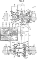
- Fig. 1 is a schematic for schematically explaining a configuration of a four-wheel drive vehicle 10 to which the present invention is preferably applied.
- the four-wheel drive vehicle 10 has an FF-based four-wheel drive device.
- the four-wheel drive device includes a first power transmission path transmitting a drive power from an engine (drive power source) 12 to a left-and-right pair of front wheels (main drive wheels) 14L, 14R, and a second power transmission path transmitting a portion of the drive power of the engine 12 to a left-and-right pair of rear wheels (sub-drive wheels) 16L, 16R in a four-wheel drive state.
- the drive power transmitted from the engine 12 through an automatic transmission 18 is transmitted through a front-wheel drive power distributing device 20 and a left-and-right pair of front wheel axles 22L, 22R to the front wheels 14L, 14R.
- a first dog clutch (dog clutch) 26 of a first connecting/disconnecting device 24 is released, and the drive power is not transmitted from the engine 12 to a transfer 28, a propeller shaft (power transmitting member) 30, a rear-wheel drive power distributing device 32, and the rear wheels 16L, 16R.
- the first dog clutch 26 and a second dog clutch 36 of a second connecting/disconnecting device 34 are both engaged and a left control coupling (electronically controlled coupling) 38L and a right control coupling (electronically controlled coupling) 38R are both engaged, so that the drive power is transmitted from the engine 12 to the transfer 28, the propeller shaft 30, the rear-wheel drive power distributing device 32, and the rear wheels 16L, 16R.
- the front-wheel drive power distributing device 20 includes a first differential device 40 disposed rotatably around a first rotation axis C1.
- the first differential device 40 includes a ring gear 40r meshed with an output gear 18a of the automatic transmission 18, a differential casing 40c integrally fixed to the ring gear 40r and having a pair of side gears 40s assembled therein, etc.
- the first differential device 40 configured as described above transmits the drive power to the front wheels 14L, 14R while allowing a differential rotation of the left and right front wheel axles 22L, 22R.
- the differential casing 40c is provided with inner circumferential meshing teeth 40a fitted to first outer circumferential spline teeth 42a formed on an axial end portion on the front wheel 14L side of an input shaft 42 (first input rotating member) disposed in the transfer 28.
- first outer circumferential spline teeth 42a formed on an axial end portion on the front wheel 14L side of an input shaft 42 (first input rotating member) disposed in the transfer 28.
- the transfer 28 includes the cylindrical input shaft 42, a cylindrical first ring gear 46 (first output rotating member), and the first connecting/disconnecting device 24.
- the first ring gear 46 is meshed with a driven pinion 44 (see Fig. 1 ) coupled to an end portion of the propeller shaft 30 on the side of the front wheels 14L, 14R.
- the first connecting/disconnecting device 24 selectively disconnects or connects a power transmission path between the input shaft 42 and the first ring gear 46, i.e., a power transmission path between the engine 12 and the propeller shaft 30.
- the transfer 28 outputs to the propeller shaft 30 a portion of the drive power transmitted from the engine 12 to the differential casing 40c.
- the cylindrical first ring gear 46 is a bevel gear having helical teeth or a hypoid gear formed thereon, for example.
- the first ring gear 46 is provided with a shaft portion 46a projected in a substantially cylindrical shape from an inner circumferential portion of the first ring gear 46 toward the front wheel 14R.
- the cylindrical first ring gear 46 has the shaft portion 46a supported by a first casing 48 via a bearing 50 disposed in the first casing 48 housing the first connecting/disconnecting device 24 etc. and is thereby supported rotatably around the first rotation axis C1 in a cantilevered manner.
- the second dog clutch 36, the left control coupling 38L, and the right control coupling 38R are each engaged, the first ring gear 46 is coupled to the rear wheels 16L, 16R in a power transmittable manner via the propeller shaft 30 etc.
- the cylindrical input shaft 42 penetrates through the cylindrical first ring gear 46, and a portion of the input shaft 42 is disposed inside the first ring gear 46.
- the cylindrical input shaft 42 has both end portions supported by the first casing 48 via a pair of bearings 52a, 52b disposed in the first casing 48, so that the input shaft 42 is supported pivotally around the first rotation axis C1.
- the input shaft 42 is rotatably supported concentrically with the first ring gear 46.
- the cylindrical input shaft 42 is provided with the first outer circumferential spline teeth 42a formed on an outer circumferential surface of the axial end portion of the input shaft 42 on the front wheel 14L side, second outer circumferential spline teeth 42b formed on an outer circumferential surface of a central portion of the input shaft 42, and third outer circumferential spline teeth 42c formed on an outer circumferential surface of the end portion of the input shaft 42 on the front wheel 14R side.
- the first dog clutch 26 includes a plurality of first meshing teeth 46c and a cylindrical first movable sleeve 54.
- the first meshing teeth 46c are formed on a side surface 46b of the shaft portion 46a of the first ring gear 46 on the front wheel 14L side.
- the first movable sleeve 54 is provided with a plurality of first meshing teeth 54a that can mesh with the first meshing teeth 46c.
- the first movable sleeve 54 is provided with inner circumferential meshing teeth 54b meshed with the second outer circumferential spline teeth 42b formed on the input shaft 42 relatively non-rotatably around the first rotation axis C1 with respect to the input shaft 42 and relatively movably in a first rotation axis C1 direction with respect to the input shaft 42.
- the first movable sleeve 54 is configured such that when the first movable sleeve 54 is moved in the first rotation axis C1 direction by a first moving device 56 disposed in the first connecting/disconnecting device 24, the first meshing teeth 54a of the first movable sleeve 54 selectively mesh with the first meshing teeth 46c of the first ring gear 46.
- the first moving device 56 selectively moves the first movable sleeve 54 in the first rotation axis C1 direction to a first meshing position and a first non-meshing position to selectively engage the first dog clutch 26.
- the first meshing position is a position at which the first meshing teeth 54a of the first movable sleeve 54 are meshed with the first meshing teeth 46c of the first ring gear 46. At the first meshing position, the first ring gear 46 and the first movable sleeve 54 cannot relatively rotate, and the first dog clutch 26 is engaged.
- the first non-meshing position is a position at which the first meshing teeth 54a of the first movable sleeve 54 are not meshed with the first meshing teeth 46c of the first ring gear 46.
- the first ring gear 46 and the first movable sleeve 54 can relatively rotate, and the first dog clutch 26 is released. Therefore, the first dog clutch 26 connects the power transmission path between the first ring gear 46 and the input shaft 42 when the first movable sleeve 54 is moved to the first meshing position by the first moving device 56, and disconnects the power transmission path between the first ring gear 46 and the input shaft 42 when the first movable sleeve 54 is moved to the first non-meshing position by the first moving device 56.
- the input shaft 42 is an input rotating member to which a portion of the drive power from the engine 12 toward the front wheels 14L, 14R is input
- the first ring gear 46 is an output rotating member coupled to the rear wheels 16L, 16R in a power transmittable manner.
- the first moving device 56 includes a first electromagnetic actuator 58 and a first ratchet mechanism 60.
- the first electromagnetic actuator 58 includes, for example, a first ball cam 62, a first electromagnetic coil 64, a first auxiliary clutch 66, etc.
- a first movable piece 68 is attracted by the first electromagnetic coil 64 and a rotation braking torque is generated in an annular second cam member 72 via a first auxiliary clutch 66 while the input shaft 42 is rotating, i.e., during vehicle running, the annular second cam member 72 and an annular first cam member 70 are relatively rotated to move the first cam member 70 in the first rotation axis C1 direction.
- the first ball cam 62 includes the first and second cam members 70 and 72, as described below.
- the first ratchet mechanism 60 retains a movement position of the first movable sleeve 54 moved in the first rotation axis C1 direction due to the movement of the first cam member 70.
- the first moving device 56 includes a first spring 74 constantly urging the first movable sleeve 54 from the first non-meshing position toward the first meshing position, i.e., constantly urging the first movable sleeve 54 toward the front wheel 14R in the first rotation axis C1 direction.
- the first ratchet mechanism 60 includes an annular first piston 70a, an annular second piston 76, and an annular holder 78 having a plurality of latching teeth, i.e., first latching teeth 78a and second latching teeth 78b, in a circumferential direction.
- the first ratchet mechanism 60 includes a coil spring 80 disposed in a compressed state between the second piston 76 and the first cam member 70 so as to constantly urge the first cam member 70 toward the second cam member 72.
- the first piston 70a is reciprocated in the first rotation axis C1 direction with a predetermined stroke by the first ball cam 62 due to the first electromagnetic coil 64 attracting the first movable piece 68 and not attracting the first movable piece 68. Therefore, the first piston 70a is reciprocated in the first rotation axis C1 direction with the predetermined stroke by the operation of the first electromagnetic actuator 58.
- the second piston 76 moves the first movable sleeve 54 to the first non-meshing position against urging force of the first spring 74 due to the reciprocation of the first piston 70a in the first rotation axis C1 direction.
- the holder 78 latches the second piston 76 moved by the first piston 70a with one of the first latching teeth 78a and the second latching teeth 78b.
- the first piston 70a is disposed on the input shaft 42 relatively non-rotatably with respect to the input shaft 42 and movably in the first rotation axis C1 direction with respect to the input shaft 42.
- the second piston 76 is disposed on the input shaft 42 relatively rotatably with respect to the input shaft 42 and movably in the first rotation axis C1 direction with respect to the input shaft 42.
- the holder 78 is disposed on the input shaft 42 relatively non-rotatably with respect to the input shaft 42 and immovably in the first rotation axis C1 direction with respect to the input shaft 42.
- the first ball cam 62 includes an annular pair of the first cam member 70 and the second cam member 72, and a plurality of spherical rolling elements 82.
- the first cam member 70 and the second cam member 72 are inserted in an overlapping manner in the first rotation axis C1 direction between the second piston 76 of the first ratchet mechanism 60 and the bearing 52b.
- the spherical rolling elements 82 are sandwiched between a cam surface 70b formed on the first cam member 70 and a cam surface 72a formed on the second cam member 72.
- the first cam member 70 and the second cam member 72 are relatively rotated in the first ball cam 62 configured as described above, the first cam member 70 is separated from the second cam member 72 in the first rotation axis C1 direction.
- the first cam member 70 is provided with inner circumferential teeth 70c meshed with the third outer circumferential spline teeth 42c.
- the inner circumferential teeth 70c make the first cam member 70 relatively non-rotatable around the first rotation axis C1 with respect to the input shaft 42 and relatively movable in the first rotation axis C1 direction with respect to the input shaft 42.
- the first auxiliary clutch 66 includes the first movable piece 68 described above, a pair of disk-shaped first friction plates 84, 86 disposed between the first movable piece 68 and the first electromagnetic coil 64, and a disk-shaped second friction plate 88 disposed between the pair of first friction plates 84, 86.
- Outer circumferential portions of the pair of first friction plates 84, 86 are provided with outer circumferential teeth 84a, 86a respectively, meshed with inner circumferential spline teeth 48a formed on the first casing 48.
- the outer circumferential teeth 84a, 86a make the first friction plates 84, 86 relatively non-rotatable around the first rotation axis C1 with respect to the first casing 48 and relatively movable in the first rotation axis C1 direction with respect to the first casing 48.
- An inner circumferential portion of the second friction plate 88 is provided with inner circumferential teeth 88a meshed with outer circumferential spline teeth 72b formed on an outer circumferential portion of the second cam member 72.
- the inner circumferential teeth 88a make the second friction plate 88 relatively non-rotatable around the first rotation axis C1 with respect to the second cam member 72 and relatively movable in the first rotation axis C1 direction with respect to the second cam member 72.
- first electromagnetic actuator 58 configured as described above, for example, when a first clutch drive current Ia1 (A) (see Fig. 1 ) is supplied to the first electromagnetic coil 64 from an electronic control device (control device) 100 described later and the first movable piece 68 is attracted by the first electromagnetic coil 64 while the input shaft 42 is rotating i.e. during vehicle running, the first friction plates 84, 86 and the second friction plate 88 of the first auxiliary clutch 66 are clamped due to the first movable piece 68 between the first movable piece 68 and the first electromagnetic coil 64, so that a rotation braking torque is transmitted to the second friction plate 88, i.e., to the second cam member 72.
- Ia1 A
- first cam member 70 and the second cam member 72 are relatively rotated by the rotation braking torque, and the first piston 70a formed integrally with the first cam member 70 moves toward the front wheel 14L against the urging forces of the first spring 74 and the coil spring 80 in the first rotation axis C1 direction with respect to the second cam member 72 via the spherical rolling elements 82.
- the first piston 70a is reciprocated once in the first rotation axis C1 direction toward the front wheel 14L and the front wheel 14R by the first electromagnetic actuator 58 in the first connecting/disconnecting device 24, as shown in Fig. 2 , the first movable sleeve 54 is moved via the first ratchet mechanism 60 to the first non-meshing position against the urging force of the first spring 74, and the second piston 76 is latched on the first latching teeth 78a of the holder 78.
- the first piston 70a when the first piston 70a is reciprocated twice by the first electromagnetic actuator 58, i.e., when the first piston 70a is further reciprocated once while the first movable sleeve 54 is disposed at the first non-meshing position in the first connecting/disconnecting device 24, the second piston 76 is unlatched from the first latching teeth 78a of the holder 78, and when the second piston 76 is latched on the second latching teeth 78b of the holder 78, the first movable sleeve 54 is moved to the first meshing position by the urging force of the first spring 74.
- the first connecting/disconnecting device 24 includes a synchronizing device 90.
- the synchronizing device 90 includes, for example, a first friction engagement member 92 meshed with outer circumferential spline teeth 54c formed on the first movable sleeve 54 such that the first friction engagement member 92 is relatively non-rotatable with respect to the first movable sleeve 54 and is movable in the first rotation axis C1 direction with respect to the first movable sleeve 54, a second friction engagement member 94 meshed with inner circumferential spline teeth 46d formed on the first ring gear 46 such that the second friction engagement member 94 is relatively non-rotatable with respect to the first ring gear 46 and is movable in the first rotation axis C1 direction with respect to the first ring gear 46, etc.
- the first friction engagement member 92 coupled to the first movable sleeve 54 in a power transmittable manner is frictionally engaged with the second friction engagement member 94 coupled to the first ring gear 46 in a power transmittable manner, and rotation speed of the first movable sleeve 54 is synchronized with rotation speed of the first ring gear 46.
- the first movable sleeve 54 indicated by a dashed-dotted line in Fig. 2 is the first movable sleeve 54 when the first movable sleeve 54 is moved against the urging force of the first spring 74 beyond the first non-meshing position toward the front wheel 14L.
- the rear-wheel drive power distributing device 32 includes: a second ring gear (second input rotating member) 98 meshed with a drive pinion 96 disposed integrally with an end portion of the propeller shaft 30 on the side of the rear wheels 16L, 16R in a power transmission path from the propeller shaft 30 to the rear wheels 16L, 16R; a cylindrical center axle (second output rotating member) 106 supported by a second casing 104 of the rear-wheel drive power distributing device 32 via bearings 102a, 102b rotatably around a second rotation axis C2; the left control coupling 38L (see Fig.
- the center axle 106 is connected to the rear wheels 16L, 16R in a power transmittable manner via the left control coupling 38L and the right control coupling 38R.
- the left control coupling 38L transmits the transmission torque corresponding to the left coupling drive current (torque command value) Icpl (A), and the left control coupling 38L couples the rear wheel 16L to the center axle 106 in a power transmittable manner when the left coupling drive current Icpl (A) is supplied from the electronic control device 100 to the electromagnetic coil.
- the right control coupling 38R transmits the transmission torque corresponding to the right coupling drive current (torque command value) Icpr (A), and the right control coupling 38R couples the rear wheel 16R to the center axle 106 in a power transmittable manner when the right coupling drive current Icpr (A) is supplied from the electronic control device 100 to the electromagnetic coil.
- the left control coupling 38L and the right control coupling 38R adjust the drive power transmitted from the engine 12 to the rear wheels 16L, 16R in accordance with the left coupling drive current Icpl and the right coupling drive current Icpr respectively.
- the right control coupling 38R is coupled to the rear wheel 16R via the rear wheel axle 108R
- the left control coupling 38L is coupled to the rear wheel 16L via the rear wheel axle 108L.
- the center axle 106 is disposed between the right control coupling 38R and the left control coupling 38L, i.e., between the rear wheel 16R and the rear wheel 16L
- the center axle 106 is coupled to a coupling cover 38Ra (see Fig. 1 ) disposed on the right control coupling 38R and a coupling cover 38La (see Fig. 1 ) disposed on the left control coupling 38L.
- the cylindrical second ring gear 98 is a bevel gear having helical teeth or a hypoid gear formed thereon, for example.
- the second ring gear 98 is provided with a shaft portion 98a projected in a substantially cylindrical shape from an inner circumferential portion of the second ring gear 98 toward the rear wheel 16L.
- the second ring gear 98 has the shaft portion 98a supported by the second casing 104 via a bearing 109 disposed in the second casing 104 and is thereby supported rotatably around the second rotation axis C2 in a cantilevered manner.
- the cylindrical center axle 106 penetrates through the cylindrical second ring gear 98 so that a portion of the center axle 106 is disposed inside the second ring gear 98.
- the cylindrical center axle 106 has both end portions supported by a pair of the bearings 102a, 102b disposed in the second casing 104, and the center axle 106 is thereby pivotally supported around the second rotation axis C2, i.e., rotatably supported concentrically with the second ring gear 98.
- the second dog clutch 36 includes a plurality of second meshing teeth 98b and a cylindrical second movable sleeve 110.
- the second meshing teeth 98b are formed on the second ring gear 98.
- the second movable sleeve 110 is provided with a plurality of second meshing teeth 110a that can mesh with the second meshing teeth 98b.
- the second movable sleeve 110 is provided with inner circumferential meshing teeth 110b meshed with outer circumferential spline teeth 106a formed on the center axle 106.
- the inner circumferential meshing teeth 110b make the second movable sleeve 110 relatively non-rotatable around the second rotation axis C2 with respect to the center axle 106 and relatively movable in the second rotation axis C2 direction with respect to the center axle 106.
- the second movable sleeve 110 is configured such that when the second movable sleeve 110 is moved in the second rotation axis C2 direction by a second moving device 112 disposed in the second connecting/disconnecting device 34, the second meshing teeth 110a of the second movable sleeve 110 selectively mesh with the second meshing teeth 98b of the second ring gear 98.
- the second moving device 112 selectively moves the second movable sleeve 110 in the second rotation axis C2 direction to a second meshing position and a second non-meshing position to selectively engage the second dog clutch 36.
- the second meshing position is a position at which the second meshing teeth 110a of the second movable sleeve 110 are meshed with the second meshing teeth 98b of the second ring gear 98.
- the second ring gear 98 and the second movable sleeve 110 cannot relatively rotate, and the second dog clutch 36 is engaged.
- the second non-meshing position is a position at which the second meshing teeth 110a of the second movable sleeve 110 are not meshed with the second meshing teeth 98b of the second ring gear 98.
- the second ring gear 98 and the second movable sleeve 110 can relatively rotate, and the second dog clutch 36 is released.
- the second dog clutch 36 connects the power transmission path between the second ring gear 98 and the center axle 106 when the second movable sleeve 110 is moved to the second meshing position by the second moving device 112, and disconnects the power transmission path between the second ring gear 98 and the center axle 106 when the second movable sleeve 110 is moved to the second non-meshing position by the second moving device 112.
- the second ring gear 98 is an input rotating member to which a portion of the drive power from the engine 12 toward the front wheels 14L, 14R is input
- the center axle 106 is an output rotating member coupled to the rear wheels 16L, 16R in a power transmittable manner.
- the second moving device 112 includes a second electromagnetic actuator 114 and a second ratchet mechanism 116.
- the second electromagnetic actuator 114 includes, for example, a second ball cam 118, a second electromagnetic coil 120, a second auxiliary clutch 122, etc.
- a second movable piece 124 is attracted by the second electromagnetic coil 120 and a rotation braking torque is generated in an annular second cam member 128 via the second auxiliary clutch 122 while the center axle 106 is rotating
- the annular second cam member 128 and an annular first cam member 126 are relatively rotated to move the first cam member 126 in the second rotation axis C2 direction.
- the second ball cam 118 includes the first cam member 126 and the second cam member 128, as described below.
- the second ratchet mechanism 116 retains a movement position of the second movable sleeve 110 moved in the second rotation axis C2 direction due to the movement of the first cam member 126.
- the second moving device 112 includes a second spring 130 constantly urging the second movable sleeve 110 from the second non-meshing position toward the second meshing position, i.e., constantly urging the second movable sleeve 110 toward the rear wheel 16L in the second rotation axis C2 direction.
- the second ratchet mechanism 116 includes an annular first piston 126a, an annular second piston 132, and an annular holder 134 having a plurality of latching teeth, i.e., first meshing teeth 134a and second meshing teeth 134b, in a circumferential direction.
- the second ratchet mechanism 116 includes a coil spring 136 disposed in a compressed state between the holder 134 and the first cam member 126 so as to constantly urge the first cam member 126 in the direction toward the second cam member 128.
- the first piston 126a is reciprocated in the second rotation axis C2 direction with a predetermined stroke by the second ball cam 118 due to the second electromagnetic coil 120 attracting the second movable piece 124 and not attracting the second movable piece 124. Therefore, the first piston 126a is reciprocated in the second rotation axis C2 direction with a predetermined stroke by the operation of the second electromagnetic actuator 114.
- the second piston 132 moves the second movable sleeve 110 to the second non-meshing position against the urging force of the second spring 130 due to the reciprocation of the first piston 126a in the second rotation axis C2 direction.
- the holder 134 latches the second piston 132 moved by the first piston 126a with any one of the first latching teeth 134a and the second latching teeth 134b.
- the first piston 126a is disposed on the center axle 106 relatively non-rotatably with respect to the center axle 106, and movably in the second rotation axis C2 direction with respect to the center axle 106.
- the second piston 132 is disposed on the center axle 106 relatively rotatably with respect to the center axle 106 and movably in the second rotation axis C2 direction with respect to the center axle 106.
- the holder 134 is disposed on the center axle 106 relatively non-rotatably with respect to the center axle 106 and immovably in the second rotation axis C2 direction with respect to the center axle 106.
- the second ball cam 118 includes an annular pair of the first cam member 126 and the second cam member 128, and a plurality of spherical rolling elements 138.
- the first cam member 126 and the second cam member 128 are inserted in an overlapping manner in the second rotation axis C2 direction between the second piston 132 of the second ratchet mechanism 116 and the bearing 102b.
- the spherical rolling elements 138 are sandwiched between a cam surface 126b formed on the first cam member 126 and a cam surface 128a formed on the second cam member 128.
- the first cam member 126 is provided with inner circumferential teeth (not shown) meshed with the outer circumferential spline teeth (not shown) formed on the center axle 106.
- the above-described inner circumferential teeth make the first cam member 126 relatively non-rotatable around the second rotation axis C2 with respect to the center axle 106 and relatively movable in the second rotation axis C2 direction with respect to the center axle 106.
- the second auxiliary clutch 122 includes the second movable piece 124 described above, and a friction plate 140 disposed between the second movable piece 124 and the second electromagnetic coil 120.
- the second movable piece 124 is disposed on the second cam member 128 relatively non-rotatably around the second rotation axis C2 with respect to the second cam member 128 and relatively movably in the second rotation axis C2 direction with respect to the second cam member 128.
- the second electromagnetic actuator 114 configured as described above, for example, when a second clutch drive current Ia2 (A) is supplied to the second electromagnetic coil 120 from the electronic control device 100 and the second movable piece 124 is attracted via the friction plate 140 by the second electromagnetic coil 120 while the center axle 106 is rotating, a rotation braking torque is transmitted from the second movable piece 124 to the second cam member 128.
- a second clutch drive current Ia2 (A) is supplied to the second electromagnetic coil 120 from the electronic control device 100 and the second movable piece 124 is attracted via the friction plate 140 by the second electromagnetic coil 120 while the center axle 106 is rotating
- first cam member 126 and the second cam member 128 are relatively rotated by the rotation braking torque, and the first piston 126a formed integrally with the first cam member 126 moves toward the rear wheel 16L against the urging forces of the second spring 130 and the coil spring 136 in the second rotation axis C2 direction with respect to the second cam member 128 via the spherical rolling elements 138.
- the second piston 132 is unlatched from the first latching teeth 134a of the holder 134, and when the second piston 132 is latched on the second latching teeth 134b of the holder 134, the second movable sleeve 110 is moved to the second meshing position by the urging force of the second spring 130.
- the first dog clutch 26 and the second dog clutch 36 are each brought into a released state to form a two-wheel drive state in which the drive power is transmitted from the engine 12 via the front-wheel drive power distributing device 20 to the front wheels 14L, 14R.
- the first dog clutch 26 and the second dog clutch 36 are each released to form a disconnect state in which the propeller shaft 30 interrupts the power transmission from the engine 12 and the rear wheels 16L, 16R.
- the electronic control device 100 determines that a 4WD switching request is made, the first dog clutch 26 and the second dog clutch 36 are each brought into an engaged state, and the left control coupling 38L and the right control coupling 38R are each brought into an engaged state to form a four-wheel drive state in which the drive power is transmitted from the engine 12 via the front-wheel drive power distributing device 20 to the front wheels 14L, 14R and the drive power is also transmitted from the engine 12 via the propeller shaft 30 etc. to the rear wheels 16L, 16R.
- the electronic control device 100 is configured to include a so-called microcomputer including a CPU, a RAM, a ROM, and an I/O interface, for example, and the CPU executes signal processes in accordance with a program stored in advance in the ROM, while utilizing a temporary storage function of the RAM, to provide various controls of the four-wheel drive vehicle 10.
- the electronic control device 100 is supplied with various input signals detected by sensors disposed on the four-wheel drive vehicle 10.
- the signals input to the electronic control device 100 include: signals indicative of wheel speeds W (rpm), i.e., wheel speeds Wfl, Wfr, Wrl, Wrr (rpm) of the front wheels 14L, 14R and the rear wheels 16L, 16R, detected by a wheel speed sensor 150; a signal indicative of a vehicle speed V (km/h) detected by a vehicle speed sensor 152; a signal indicative of an accelerator opening degree ⁇ acc detected by an accelerator opening degree sensor 154; a signal indicative of a yaw rate Ryaw that is a rotation angular speed around a vertical axis of the vehicle 10 detected by a yaw rate sensor 156; and a signal indicative of a steering angle ⁇ sw of a steering wheel detected by a steering sensor 158.
- the signals supplied from the electronic control device 100 to the portions include: the first clutch drive current Ia1 (A) supplied to the first electromagnetic coil 64 of the first electromagnetic actuator 58 for controlling the first dog clutch 26, i.e., for switching the first dog clutch 26 to the engaged state or a released state; the second clutch drive current Ia2 (A) supplied to the second electromagnetic coil 120 of the second electromagnetic actuator 114 for controlling the second dog clutch 36, i.e., for switching the second dog clutch 36 to the engaged state or a released state; the left coupling drive current Icpl (A) supplied to the electromagnetic coil (not shown) of the left control coupling 38L for controlling the transmission torque transmitted between the rear wheel 16L and the center axle 106; and the right coupling drive current Icpr (A) supplied to the electromagnetic coil (not shown) of the right control coupling 38R for controlling the transmission torque transmitted between the rear wheel 16R and the center axle 106.
- the electronic control device 100 includes a drive state switching portion 160, and the drive state switching portion 160 includes, for example, a road surface state determining portion 162, a switching request output portion 164, and a road surface state redetermining portion 166, a coupling control portion 168, and a clutch control portion 170.
- the drive state switching portion 160 includes, for example, a road surface state determining portion 162, a switching request output portion 164, and a road surface state redetermining portion 166, a coupling control portion 168, and a clutch control portion 170.
- the road surface state determining portion 162 determines whether a running road surface is a relatively low friction road, i.e., a low ⁇ road, or a high friction road, i.e., a high ⁇ road, during vehicle running. For example, when a difference between a vehicle body speed Ws (rpm) and the wheel speed W (rpm) becomes larger than a preset slip determination value where the wheel speed W is one of the wheel speeds WF1, Wfr, Wrl, Wrr whose difference from the vehicle body speed Ws (rpm) is the largest, the road surface state determining portion 162 determines that the road surface state is the low ⁇ road.
- the vehicle body speed Ws (rpm) is calculated by using a preset equation from the wheel speeds Wfl, Wfr, Wrl, Wrr (rpm) detected by the wheel speed sensor 150.
- the road surface state determining portion 162 can relatively accurately determine whether the running road surface is the low ⁇ road or the high ⁇ road when the drive power is transmitted from the wheels 14, 16 to the running road surface during vehicle running; however, for example, if the drive power is not transmitted from the wheels 14, 16 to the running road surface during coasting or deceleration running of the vehicle 10, the road surface state determining portion 162 may determine the running road surface as the high ⁇ road even though the running road surface is actually the low ⁇ road.
- the switching request output portion 164 outputs a request for switching to the two-wheel drive state, i.e., the 2WD switching request, or a request for switching to the four-wheel drive state, i.e., the 4WD switching request.
- the switching request output portion 164 outputs the 4WD switching request based on the determination.
- the road surface state determining portion 162 determines that the running road surface is the high ⁇ road and the vehicle is in a steady running state in which a drive power change of the vehicle 10 calculated from the accelerator opening degree ⁇ acc, vehicle speed V, etc.
- the switching request output portion 164 outputs the 2WD switching request. Therefore, the switching request output portion 164 outputs the 4WD switching request or the 2WD switching request depending on a determination whether the running road surface is the low ⁇ road or the high ⁇ road according to the road surface state determining portion 162.
- the drive state switching portion 160 switches the drive state of the four-wheel drive vehicle 10 from the four-wheel drive state to the two-wheel drive state.
- the drive state switching portion 160 maintains the drive state.
- the drive state switching portion 160 switches the drive state of the four-wheel drive vehicle 10 from the two-wheel drive state to the four-wheel drive state.
- the drive state switching portion 160 maintains the drive state.
- the road surface state redetermining portion 166 includes a storage portion 166a.
- the storage portion 166a calculates a slip ratio S and a yaw rate deviation ⁇ Ryaw and stores the calculated slip ratio S and yaw rate deviation ⁇ Ryaw as a slip ratio Sp and a yaw rate deviation ⁇ Ryawp, respectively. Therefore, the storage portion 166a calculates each of the slip ratio S and the yaw rate deviation ⁇ Ryaw when the drive state is the four-wheel drive state, and stores each of the calculated slip ratio S and yaw rate deviation ⁇ Ryaw.
- Ws is the vehicle body speed Ws described above, and “W” is the wheel speed W having a largest difference from the vehicle body speed Ws among the wheel speeds Wfl, Wfr, Wrl, Wrr.
- “Ryawtgt” described in the Eq. (2) is a target yaw rate calculated based on the vehicle speed V, the steering angle ⁇ sw, etc.
- the coupling control portion 168 stops the supply of the left coupling drive current Icpl supplied to the electromagnetic coil of the left control coupling 38L and stops the supply of the right coupling drive current Icpr supplied to the electromagnetic coil of the right control coupling 38R, i.e., cuts off the energization to the left control coupling 38L and the right control coupling 38R, so as to temporarily release the left control coupling 38L and the right control coupling 38R, respectively, to bring the drive state into the two-wheel drive state in which the drive power from the engine 12 is distributed only to the front wheels 14L, 14R.
- the road surface state redetermining portion 166 calculates each of the slip ratio S and the yaw rate deviation ⁇ Ryaw to redetermine whether the running road surface is the low ⁇ road or the high ⁇ road for reconfirmation based on the calculated slip ratio S and yaw rate deviation ⁇ Ryaw as well as the slip ratio Sp and the yaw rate deviation ⁇ Ryawp stored in the storage portion 166a while the energization to the left control coupling 38L and the right control coupling 38R is temporarily cut off by the coupling control portion 168.
- the road surface state redetermining portion 166 calculates the slip ratio S when the left control coupling 38L and the right control coupling 38R are released, i.e., during the two-wheel drive state, and redetermines that the running road surface is the low ⁇ road if the calculated slip ratio S becomes equal to or greater than a threshold value Sa or redetermines that the running road surface is the high ⁇ road if the calculated slip ratio S is smaller than the threshold value Sa during a preset first time tc1.
- the threshold value Sa is a slip ratio determination value for determining whether the running road surface is the low ⁇ road or the high ⁇ road, and the threshold value Sa is calculated by using, for example, a map stored in advance from the slip ratio Sp stored in the storage portion 166a.
- the road surface state redetermining portion 166 calculates the yaw rate deviation ⁇ Ryaw while the left control coupling 38L and the right control coupling 38R are released, i.e., during the two-wheel drive state, and redetermines that the running road surface is the low ⁇ road if a change amount H ( ⁇ Ryaw- ⁇ Ryawp) between the calculated yaw rate deviation ⁇ Ryaw and the yaw rate deviation ⁇ Ryawp stored in the storage portion 166a becomes equal to or greater than a predetermined change amount (determination value) H1 set in advance, or redetermines that the running road surface is the high ⁇ road if the change amount H is smaller than the predetermined change amount HI during a preset second time tc2.
- the predetermined change amount H1 is a yaw rate deviation determination value for determining whether the running road surface is the low ⁇ road or the high ⁇ road.
- the road surface redetermining portion 166 redetermines that the running road surface is the low ⁇ road when at least one redetermination result that the running road surface is the low ⁇ road is obtained by redeterminations using the slip ratio S and the yaw rate deviation ⁇ Ryaw.
- the drive state switching portion 160 prohibits switching the four-wheel drive vehicle 10 from the four-wheel drive state to the two-wheel drive state.
- the coupling control portion 168 supplies the left coupling drive current Icpl to the electromagnetic coil of the left control coupling 38L and supplies the right coupling drive current Icpr to the electromagnetic coil of the right control coupling 38R so as to engage the left control coupling 38L and the right control coupling 38R, respectively, to bring the drive state into the four-wheel drive state.
- the road surface state determining portion 162 corrects the running road surface once determined by the road surface state determining portion 162 from the high ⁇ road to the low ⁇ road.
- the switching request output portion 164 outputs the 4WD switching request.
- the clutch control portion 170 controls the first clutch drive current Ia1 (A) supplied to the first electromagnetic coil 64 of the first electromagnetic actuator 58 and the second clutch drive current Ia2 (A) supplied to the second electromagnetic coil 120 of the second electromagnetic actuator 114 so that the first dog clutch 26 and the second dog clutch 36 are each switched from the engaged state to the released state.
- Fig. 4 is a flowchart of the electronic control device 100 for explaining an example of a control operation of a switching control i.e. switching the drive state of the vehicle 10 from the four-wheel drive state to the two-wheel drive state during running in the four-wheel drive state when it is determined that the running road surface is the high ⁇ road.
- Fig. 6 is a time chart in the case of performing the control operation along the flowchart of Fig. 4 , i.e., the control operation of the switching control from the four-wheel drive state to the two-wheel drive state while the vehicle 10 is making a turn in the four-wheel drive state when it is determined that the running road surface is the high ⁇ road even though the running road surface is actually the low ⁇ road as shown in Fig. 5 .
- S5 corresponding to the function of the road surface state redetermining portion 166, it is redetermined whether the running road surface is the low ⁇ road based on the slip ratio S and the yaw rate deviation ⁇ Ryaw calculated at S4 and the slip ratio S and the yaw rate deviation ⁇ Ryaw stored at S2. If the determination of S5 is negative, i.e., if the running road surface is the high ⁇ road, S6 corresponding to the function of the clutch control portion 170 is executed, and if the determination of S5 is affirmative (at time t2 of Fig. 6 ), S7 corresponding to the function of the drive state switching portion 160 is executed. At S6, the first dog clutch 26 and the second dog clutch 36 are each switched from the engaged state to the released state for switching from the four-wheel drive state to the two-wheel drive state.
- the left coupling drive current Icpl is supplied to the electromagnetic coil of the left control coupling 38L and the right coupling drive current Icpr is supplied to the electromagnetic coil of the right control coupling 38R so as to engage the left control coupling 38L and the right control coupling 38R, respectively.
- the left control coupling 38L and the right control coupling 38R are respectively engaged so that the drive state is switched to the four-wheel drive state.
- the determined running road surface is corrected from the high ⁇ road to the low ⁇ road.
- the left control coupling 38L and the right control coupling 38R are temporarily released to redetermine whether the running road surface is the low ⁇ road or the high ⁇ road before releasing the first dog clutch 26 and the second dog clutch 36, and when it is redetermined that the running road surface is the low ⁇ road, switching from the four-wheel drive state to the two-wheel drive state is prohibited.
- the left control coupling 38L and the right control coupling 38R are switched quicker than the first dog clutch 26 and the second dog clutch 36 between the engaged state and the released state, the left control coupling 38L and the right control coupling 38R are temporarily released to establish the two-wheel drive state in which the drive power from the engine 12 is distributed only to the front wheels 14L, 14R and to redetermine whether the running road surface is the low ⁇ road or the high ⁇ road, and when it is redetermined that the running road surface is the low ⁇ road, switching from the four-wheel drive state to the two-wheel drive state is prohibited, so that inappropriate release of the first dog clutch 26 and the second dog clutch 36 is suitably prevented when the running road surface is the low ⁇ road.
- the vehicle 10 includes the first dog clutch 26 selectively disconnecting or connecting the power transmission path between the input shaft 42 to which a portion of the drive power from the engine 12 toward the front wheels 14L, 14R is input and the first ring gear 46 coupled via the propeller shaft 30 to the rear wheels 16L, 16R, and the second dog clutch 36 selectively disconnecting or connecting the power transmission path between the second ring gear 98 coupled to the propeller shaft 30 and the center axle 106 coupled to the rear wheels 16L, 16R, with the left control coupling 38L and the right control coupling 38R disposed on the power transmission path between the center axle 106 and the rear wheels 16L, 16R, and the electronic control device 100 provides the switching control between the four-wheel drive state in which the first dog clutch 26 and the second dog clutch 36 are each brought into the engaged state while the left control coupling 38L and the right control coupling 38R are each brought into the engaged state and the two-wheel drive state in which the first dog clutch 26 and the second dog clutch 36 are each brought
- the electronic control device 100 redetermines that the running road surface is the low ⁇ road when the change amount H exceeds the predetermined change amount HI set in advance between the yaw rate deviation ⁇ Ryawp before temporarily releasing the left control coupling 38L and the right control coupling 38R and the yaw rate deviation ⁇ Ryaw when the left control coupling 38L and the right control coupling 38R are temporarily released. Therefore, it can suitably be redetermined whether the running road surface is the low ⁇ road or the high ⁇ road.
- the left control coupling 38L and the right control coupling 38R are respectively coupled to the rear wheels 16L, 16R. Therefore, the present invention can suitably be applied to the four-wheel drive vehicle including the left-and-right pair of the left control coupling 38L and the right control coupling 38R for the rear wheels 16L, 16R.
- the main drive wheels are the front wheels 14L, 14R
- the sub-drive wheels are the rear wheels 16L, 16R. Therefore, the present invention can suitably be applied to an FF (front-engine front-wheel drive) type four-wheel drive vehicle.
- Fig. 7 is a time chart in a case of performing another example of control operation of switching control from the four-wheel drive state to the two-wheel drive state when it is determined that the running road surface is a high ⁇ road even though the running road surface is actually the low ⁇ road, and the vehicle 10 is making a turn in the four-wheel drive state.
- the four-wheel drive vehicle of this example is substantially the same as the four-wheel drive vehicle 10 of the first example except that the method of redetermining whether the running road surface is the high ⁇ road or the low ⁇ road by using the slip ratio S is different from that in the road surface state redetermining portion 166 included in the electronic control device 100 of the first example.
- the road surface state redetermining portion 166 calculates the slip ratio S while the left control coupling 38L and the right control coupling 38R are released, and redetermines that the running road surface is the low ⁇ road when the calculated slip ratio S becomes equal to or larger than a first threshold value Sa1 as shown in Fig. 7 .
- the road surface state redetermining portion 166 calculates the slip ratio S while the left control coupling 38L and the right control coupling 38R are released, and redetermines that the running road surface is the low ⁇ road when the calculated slip ratio S exceeds a second threshold value Sa2 set smaller than the first threshold value Sa1 and the slip ratio S exceeds the second threshold value Sa2 for a time longer than a predetermined time tc set in advance.
- the predetermined time tc is a time (sec) obtained in advance by an experiment etc. to prevent an errorneous redetermination that the running road surface is the low ⁇ road even if a spike-shaped slip occurs and causes the slip ratio S temporarily exceeding the second threshold value Sa2 during the vehicle 10 running on the high ⁇ road and passing through unevenness, for example.
- the spike-shaped slip is indicated by a dashed-dotted line L.
- the first threshold value Sa1 is a magnitude of the slip ratio S set sufficiently larger than the slip ratio S of the spike-shaped slip, for example.
- the first threshold value Sa1 is decided by using, for example, a map stored in the storage portion 166a in advance and the slip ratio Sp before the left control coupling 38L and the right control coupling 38R are temporarily released, for example.
- the road surface state redetermining portion 166 calculates the slip ratio S while the left control coupling 38L and the right control coupling 38R are released, and redetermines that the running road surface is the high ⁇ road when the calculated slip ratio S is smaller than the second threshold value Sa2 during the preset first time tc1.
- the slip ratio S only temporarily exceeds the second threshold value Sa2, so that an errorneous redetermination can be avoided that the running road surface is the low ⁇ road even when the running road surface is the high ⁇ road and the vehicle passes through unevenness. If the slip ratio S exceeds the first threshold value Sa1 sufficiently larger than the slip ratio S of the spike-shaped slip, the running road surface is redetermined as the low ⁇ road even though the predetermined time tc has not elapsed. Time t1d shown in Fig.
- time t2d shown in Fig. 7 is a time point when the slip ratio S exceeds the second threshold value Sa2
- time t3d shown in Fig. 7 is a time point when the slip ratio S exceeds the first threshold value Sa1.
- the electronic control device 100 redetermines that the running road surface is the low ⁇ road when the slip ratio S exceeds the preset first threshold value Sa1 or when the slip ratio S exceeds the second threshold value Sa2 set smaller than the first threshold value Sa1 and the slip ratio S exceeds the second threshold value Sa2 for a time longer than the predetermined time tc.
- the running road surface is the low ⁇ road. If the slip ratio S exceeds the first threshold value Sa1 and it can be determined that the running road surface is the low ⁇ road, the running road surface is redetermined as the low ⁇ road even though the predetermined time tc has not elapsed, so that the time required for redetermining the running road surface as the low ⁇ road can suitably be shortened.
- the first threshold value Sa1 is decided based on the slip ratio S before each of the right control coupling 38R and the left control coupling 38L is temporarily released. Therefore, whether the running road surface is the low ⁇ road can accurately be redetermined in a short time.
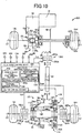
- Fig. 8 is a diagram for explaining a four-wheel drive vehicle 200 according to another example of the present invention.
- the four-wheel drive vehicle 200 of this example is substantially the same as the four-wheel drive vehicle 10 of the first example except that the left control coupling 38L and the right control coupling 38R are not provided, that an electronically controlled coupling 202 is disposed on a power transmission path between the propeller shaft 30 and the drive pinion 96, that a differential device 204 is disposed on the power transmission path between the center axle 106 and the rear wheels 16L, 16R, and that the function of the coupling control portion 168 included in the electronic control device 100 is changed.
- the electronic control device 100 determines that the 2WD switching request is made, for example, the first dog clutch 26 and the second dog clutch 36 are each brought into the released state to form the two-wheel drive state.
- the electronic control device 100 determines that the 4WD switching request is made, the first dog clutch 26 and the second dog clutch 36 are each brought into the engaged state and the electronically controlled coupling 202 is brought into an engaged state to form the four-wheel drive state.
- the electronically controlled coupling 202 includes a clutch drum 202a coupled to the propeller shaft 30 in a power transmittable manner and a clutch hub 202b coupled to the drive pinion 96 in a power transmittable manner so that the electronically controlled coupling 202 adjusts a drive torque from the propeller shaft 30 to the second ring gear 98, i.e., the torque transmitted from the engine 12 to the rear wheels 16L, 16R with the first dog clutch 26 and the second dog clutch 36 each engaged.
- the electronically controlled coupling 202 is, for example, an electromagnetic coupling including both an electrically controllable actuator that includes an electromagnetic coil and a ball cam and a wet multiplate clutch whose friction force, i.e., fastening force, between an input-side friction member (not shown) disposed on the clutch drum 202a and an output-side friction member (not shown) disposed on the clutch hub 202b is adjusted by the actuator, so that a magnetic force generated by a coupling drive current Icp supplied from the electronic control device 100 to the electromagnetic coil increases the fastening force between the input-side friction member and the output-side friction member, i.e., increases the engagement torque of the electronically controlled coupling 202, so as to adjust the drive power transmitted to the rear wheels 16L, 16R.
- an electrically controllable actuator that includes an electromagnetic coil and a ball cam and a wet multiplate clutch whose friction force, i.e., fastening force, between an input-side friction member (not shown) disposed on the clutch drum 202a
- the coupling control portion 168 stops the supply of the coupling drive current Icp supplied to the electromagnetic coil of the electronically controlled coupling 202, i.e., cuts off the energization to the electronically controlled coupling 202, so as to temporarily release the electronically controlled coupling 202 to bring the drive state into the two-wheel drive state in which the drive power from the engine 12 is distributed only to the front wheels 14L, 14R.
- the coupling control portion 168 supplies the coupling drive current Icp to the electromagnetic coil of the electronically controlled coupling 202 so as to engage the electronically controlled coupling 202 to bring the drive state into the four-wheel drive state.
- the electronically controlled coupling 202 is temporarily released to redetermine whether the running road surface is the low ⁇ road or the high ⁇ road before releasing the first dog clutch 26 and the second dog clutch 36, and when it is redetermined that the running road surface is the low ⁇ road, switching from the four-wheel drive state to the two-wheel drive state is prohibited. Therefore, in the four-wheel drive vehicle 200, the same effects as the four-wheel drive vehicle 10 of the first example can be obtained. Specifically, in the four-wheel drive vehicle 200, inappropriate release of the first dog clutch 26 and the second dog clutch 36 is suitably prevented when the running road surface is actually the low ⁇ road.
- Fig. 9 is a diagram for explaining a four-wheel drive vehicle 210 according to another example of the present invention.
- the four-wheel drive vehicle 210 of this example is substantially the same as the four-wheel drive vehicle 10 of the first example except that the first differential device 40 is removed, that a left control coupling 212L is disposed on a power transmission path between the input shaft 42 and the front wheel 14L, and that a right control coupling 212R is disposed on a power transmission path between the input shaft 42 and the front wheel 14R.
- the left control coupling 38L and the right control coupling 38R are temporarily released to redetermine whether the running road surface is the low ⁇ road or the high ⁇ road before releasing the first dog clutch 26 and the second dog clutch 36, and when it is redetermined that the running road surface is the low ⁇ road, switching from the four-wheel drive state to the two-wheel drive state is prohibited. Therefore, in the four-wheel drive vehicle 210, the same effects as the four-wheel drive vehicle 10 of the first example can be obtained. Specifically, in the four-wheel drive vehicle 210, inappropriate release of the first dog clutch 26 and the second dog clutch 36 is suitably prevented when the running road surface is actually the low ⁇ road.
- Fig. 10 is a diagram for explaining a four-wheel drive vehicle 220 according to another example of the present invention.
- the four-wheel drive vehicle 220 of this example is substantially the same as the four-wheel drive vehicle 10 of the first example except that the first dog clutch 26, i.e., the first connecting/disconnecting device 24, is removed to couple the input shaft 42 and the first ring gear 46 in a power transmittable manner, that the electronically controlled coupling 202 described above is disposed on a power transmission path between the driven pinion 44 and the propeller shaft 30, and that the functions of the coupling control portion 168 and the clutch control portion 170 included in the electronic control device 100 are partially changed.
- the first dog clutch 26, i.e., the first connecting/disconnecting device 24 is removed to couple the input shaft 42 and the first ring gear 46 in a power transmittable manner
- the electronically controlled coupling 202 described above is disposed on a power transmission path between the driven pinion 44 and the propeller shaft 30, and that the functions of the coupling control portion 168 and
- the electronically controlled coupling 202 and the second dog clutch 36 are each brought into the released state to form the two-wheel drive state.
- the electronically controlled coupling 202 and the second dog clutch 36 are each brought into the engaged state and the left control coupling 38L and the right control coupling 38R are each brought into the engaged state to form the four-wheel drive state.
- the clutch control portion 170 controls the second clutch drive current Ia2 (A) supplied to the second electromagnetic coil 120 of the second electromagnetic actuator 114 so that the second dog clutch 36 is switched from the engaged state to the released state.
- the coupling control portion 168 stops the supply of the coupling drive current Icp to the electromagnetic coil of the electronically controlled coupling 202, i.e., cuts off the energization to the electronically controlled coupling 202, so as to release the electronically controlled coupling 202.
- the left control coupling 38L and the right control coupling 38R are temporarily released to redetermine whether the running road surface is the low ⁇ road or the high ⁇ road before releasing the second dog clutch 36 and the electronically controlled coupling 202, and when it is redetermined that the running road surface is the low ⁇ road, switching from the four-wheel drive state to the two-wheel drive state is prohibited. Therefore, in the four-wheel drive vehicle 220, the same effects as the four-wheel drive vehicle 10 of the first example can be obtained. Specifically, in the four-wheel drive vehicle 220, inappropriate release of the second dog clutch 36 is suitably prevented when the running road surface is actually the low ⁇ road.
- Fig. 11 is a diagram for explaining a four-wheel drive vehicle 230 according to another example of the present invention.
- the four-wheel drive vehicle 230 of this example is substantially the same as the four-wheel drive vehicle 10 of the first example except that the second dog clutch 36, i.e., the second connecting/disconnecting device 34, is removed to couple the center axle 106 and the second ring gear 98 in a power transmittable manner, that the left control coupling 38L and the right control coupling 38R are removed, that a differential device 232 is disposed on the power transmission path between the center axle 106 and the rear wheels 16L, 16R, that the electronically controlled coupling 202 described above is disposed on the power transmission path between the propeller shaft 30 and the drive pinion 96, and that the functions of the coupling control portion 168 and the clutch control portion 170 included in the electronic control device 100 are partially changed.
- the second dog clutch 36 i.e., the second connecting/disconnecting device 34
- the electronic control device 100 determines that the 2WD switching request is made, for example, the first dog clutch 26 and the electronically controlled coupling 202 are each brought into the released state to form the two-wheel drive state.
- the electronic control device 100 determines that the 4WD switching request is made, the first dog clutch 26 and the electronically controlled coupling 202 are each brought into the engaged state to form the four-wheel drive state.
- the coupling control portion 168 stops the supply of the coupling drive current Icp supplied to the electromagnetic coil of the electronically controlled coupling 202, i.e., cuts off the energization to the electronically controlled coupling 202, so as to temporarily release the electronically controlled coupling 202 to bring the drive state into the two-wheel drive state in which the drive power from the engine 12 is distributed only to the front wheels 14L, 14R.
- the coupling control portion 168 supplies the coupling drive current Icp to the electromagnetic coil of the electronically controlled coupling 202 so as to engage the electronically controlled coupling 202 to bring the drive state into the four-wheel drive state.
- the clutch control portion 170 controls the first clutch drive current Ia1 (A) supplied to the first electromagnetic coil 64 of the first electromagnetic actuator 58 so that the first dog clutch 26 is switched from the engaged state to the released state.
- the coupling control portion 168 stops the supply of the coupling drive current Icp to the electromagnetic coil of the electronically controlled coupling 202, i.e., cuts off the energization to the electronically controlled coupling 202, so as to release the electronically controlled coupling 202.
- the electronically controlled coupling 202 is temporarily released to redetermine whether the running road surface is the low ⁇ road or the high ⁇ road before releasing the first dog clutch 26, and when it is redetermined that the running road surface is the low ⁇ road, switching from the four-wheel drive state to the two-wheel drive state is prohibited. Therefore, in the four-wheel drive vehicle 230, the same effects as the four-wheel drive vehicle 10 of the first example can be obtained. Specifically, in the four-wheel drive vehicle 230, inappropriate release of the first dog clutch 26 is suitably prevented when the running road surface is actually the low ⁇ road.
- Fig. 12 is a diagram for explaining a four-wheel drive vehicle 240 according to another example of the present invention.
- the four-wheel drive vehicle 240 of this example is substantially the same as the four-wheel drive vehicle 10 of the first example except that the first dog clutch 26, i.e., the first connecting/disconnecting device 24, is removed to couple the input shaft 42 and the first ring gear 46 in a power transmittable manner, that the left control coupling 38L and the right control coupling 38R are removed, that a differential device 242 is disposed on the power transmission path between the center axle 106 and the rear wheels 16L, 16R, that the electronically controlled coupling 202 described above is disposed on the power transmission path between the driven pinion 44 and the propeller shaft 30, that the second connecting/disconnecting device 34 is provided with a synchronizing device 244 synchronizing rotation speed of the second ring gear 98 and rotation speed of the center axle 106 when the second dog clutch 36 is switched from the released state to the
- the electronic control device 100 determines that the 2WD switching request is made, for example, the second dog clutch 36 and the electronically controlled coupling 202 are each brought into the released state to form the two-wheel drive state.
- the electronic control device 100 determines that the 4WD switching request is made, the second dog clutch 36 and the electronically controlled coupling 202 are each brought into the engaged state to form the four-wheel drive state.
- the coupling control portion 168 stops the supply of the coupling drive current Icp supplied to the electromagnetic coil of the electronically controlled coupling 202, i.e., cuts off the energization to the electronically controlled coupling 202, so as to temporarily release the electronically controlled coupling 202 to bring the drive state into the two-wheel drive state in which the drive power from the engine 12 is distributed only to the front wheels 14L, 14R.
- the coupling control portion 168 supplies the coupling drive current Icp to the electromagnetic coil of the electronically controlled coupling 202 so as to engage the electronically controlled coupling 202 to bring the drive state into the four-wheel drive state.
- the clutch control portion 170 controls the second clutch drive current Ia2 (A) supplied to the second electromagnetic coil 120 of the second electromagnetic actuator 114 so that the second dog clutch 36 is switched from the engaged state to the released state.
- the coupling control portion 168 stops the supply of the coupling drive current Icp to the electromagnetic coil of the electronically controlled coupling 202, i.e., cuts off the energization to the electronically controlled coupling 202, so as to release the electronically controlled coupling 202.
- the electronically controlled coupling 202 is temporarily released to redetermine whether the running road surface is the low ⁇ road or the high ⁇ road before releasing the second dog clutch 36, and when it is redetermined that the running road surface is the low ⁇ road, switching from the four-wheel drive state to the two-wheel drive state is prohibited. Therefore, in the four-wheel drive vehicle 240, the same effects as the four-wheel drive vehicle 10 of the first example can be obtained. Specifically, in the four-wheel drive vehicle 240, inappropriate release of the second dog clutch 36 is suitably prevented when the running road surface is actually the low ⁇ road.
- the first dog clutch 26 and the second dog clutch 36 are both disposed; however, for example, only one of the first dog clutch 26 and the second dog clutch 36 may be disposed.
- the four-wheel drive vehicle 10 of the first example described above is an FF-based (front-engine/front-drive-based) four-wheel drive vehicle
- the vehicle 10 may be an FR (front-engine rear-wheel drive) type four-wheel drive vehicle, for example.
- the electronically controlled coupling 202 is disposed on the power transmission path between the drive pinion 96 and the propeller shaft 30; however, an electronically controlled coupling having the same structure as the electronically controlled coupling 202 may further be disposed on the power transmission path between the driven pinion 44 and the propeller shaft 30.
- the four-wheel drive vehicle 200 of the third example described above includes the differential device 204; however, for example, the differential device 204 may be removed to dispose a left control coupling on the power transmission path between the center axle 106 and the rear wheel 16L and to dispose a right control coupling on the power transmission path between the center axle 106 and the rear wheel 16R, and additionally, the electronically controlled coupling 202 may be removed to dispose an electronically controlled coupling having the same structure as the electronically controlled coupling 202 on the power transmission path between the driven pinion 44 and the propeller shaft 30.
- the four-wheel drive vehicle 200 of the third example described above includes the first differential device 40; however, for example, the first differential device 40 may be removed to dispose a left control coupling on the power transmission path between the input shaft 42 and the front wheel 14L and to dispose a right control coupling on the power transmission path between the input shaft 42 and the front wheel 14R.
- the electronically controlled coupling 202 is disposed on the power transmission path between the drive pinion 96 and the propeller shaft 30; however, an electronically controlled coupling having the same structure as the electronically controlled coupling 202 may further be disposed on the power transmission path between the driven pinion 44 and the propeller shaft 30.
- the four-wheel drive vehicle 230 of the sixth example described above includes the first differential device 40; however, for example, the first differential device 40 may be removed to dispose a left control coupling on the power transmission path between the input shaft 42 and the front wheel 14L and to dispose a right control coupling on the power transmission path between the input shaft 42 and the front wheel 14R.
- the four-wheel drive vehicle 230 of the sixth example described above includes the differential device 232; however, for example, the differential device 232 may be removed to dispose a left control coupling on the power transmission path between the center axle 106 and the rear wheel 16L and to dispose a right control coupling on the power transmission path between the center axle 106 and the rear wheel 16R, and additionally, the electronically controlled coupling 202 disposed on the power transmission path between the drive pinion 96 and the propeller shaft 30 may be removed to dispose an electronically controlled coupling having the same structure as the electronically controlled coupling 202 on the power transmission path between the driven pinion 44 and the propeller shaft 30.
- the four-wheel drive vehicle 230 of the sixth example described above includes the differential device 232; however, for example, the differential device 232 may be removed to dispose a left control coupling on the power transmission path between the center axle 106 and the rear wheel 16L and to dispose a right control coupling on the power transmission path between the center axle 106 and the rear wheel 16R, and additionally, the first differential device 40 and the electronically controlled coupling 202 may be removed to dispose a left control coupling on the power transmission path between the input shaft 42 and the front wheel 14L and to dispose a right control coupling on the power transmission path between the input shaft 42 and the front wheel 14R.
- the electronically controlled coupling 202 is disposed on the power transmission path between the driven pinion 44 and the propeller shaft 30; however, an electronically controlled coupling having the same structure as the electronically controlled coupling 202 may further be disposed on the power transmission path between the drive pinion 96 and the propeller shaft 30.
- the four-wheel drive vehicle 240 of the seventh example described above includes the first differential device 40; however, for example, the first differential device 40 may be removed to dispose a left control coupling on the power transmission path between the input shaft 42 and the front wheel 14L and to dispose a right control coupling on the power transmission path between the input shaft 42 and the front wheel 14R, and additionally, the electronically controlled coupling 202 may be removed to dispose an electronically controlled coupling having the same structure as the electronically controlled coupling 202 on the power transmission path between the propeller shaft 30 and the drive pinion 96.
- the four-wheel drive vehicle 240 of the seventh example described above includes the first differential device 40; however, for example, the first differential device 40 may be removed to dispose a left control coupling on the power transmission path between the input shaft 42 and the front wheel 14L and to dispose a right control coupling on the power transmission path between the input shaft 42 and the front wheel 14R, and additionally, the electronically controlled coupling 202 and the differential device 242 may be removed to dispose a left control coupling on the power transmission path between the center axle 106 and the rear wheel 16L and to dispose a right control coupling on the power transmission path between the center axle 106 and the rear wheel 16R.
- the road surface redetermining portion 166 redetermines that the running road surface is the low ⁇ road when at least one of the redetermining results each based on the slip ratio S and the yaw rate deviation ⁇ Ryaw indicates that the running road surface is the low ⁇ road.
- the road surface redetermining portion 166 may determine that the running road surface is the low ⁇ road when both of the redetermining results indicate that the running road surface is the low ⁇ road. Otherwise, the road surface redetermining portion 166 may redetermine based on only either of the slip ratio S or the yaw rate deviation ⁇ Ryaw.
Landscapes
- Engineering & Computer Science (AREA)
- Mechanical Engineering (AREA)
- Transportation (AREA)
- Chemical & Material Sciences (AREA)
- Combustion & Propulsion (AREA)
- General Engineering & Computer Science (AREA)
- Physics & Mathematics (AREA)
- Automation & Control Theory (AREA)
- Mathematical Physics (AREA)
- Arrangement And Mounting Of Devices That Control Transmission Of Motive Force (AREA)
- Arrangement And Driving Of Transmission Devices (AREA)
Abstract
Description
- The present invention relates to a technique for appropriately controlling the dog clutch in a case where a running road surface is a low friction load, in a four-wheel drive vehicle switching to a four-wheel drive state in which a dog clutch and an electronically controlled coupling are each brought into an engaged state when it is determined that the running road surface is the low friction road and switching to a two-wheel drive state in which the dog clutch is brought into a released state when it is determined that the running road surface is a high friction road.
- There is known a four-wheel drive vehicle comprising: (a) a dog clutch selectively disconnecting or connecting a power transmission path between an input rotating member to which a portion of a drive power from a drive power source toward main drive wheels is input and an output rotating member coupled to sub-drive wheels in a power transmittable manner; (b) an electronically controlled coupling disposed on a power transmission path between the drive power source and the sub-drive wheels and adjusting the drive power transmitted from the drive power source to the sub-drive wheels; and (c) a control device providing a switching control between a four-wheel drive state in which the dog clutch is brought into an engaged state while the electronically controlled coupling is brought into an engaged state and a two-wheel drive state in which the dog clutch is brought into a released state. For example, this corresponds to a four-wheel drive vehicle described in
Patent Document 1. It is conceivable that the four-wheel drive vehicle as described inPatent Document 1 determines whether a running road surface is a low friction road or a high friction road so as to switch a drive state between the two-wheel drive state and the four-wheel drive state depending on the determination of the running road surface. Specifically, it is conceivable that the four-wheel drive vehicle switches the drive state to the four-wheel drive state when the control device determines that the running road surface is the low friction road and switches the drive state to the two-wheel drive state when the control device determines that the running road surface is the high friction road. - Patent Document 1: Japanese Laid-Open Patent Publication No.
2015-224005 - It is conceivable that the four-wheel drive vehicle as described above determines whether the running road surface is the low friction road or the high friction road, for example, based on a slip of a wheel during vehicle running. In such a four-wheel drive vehicle, it is determined whether the running road surface is the low friction road or the high friction road when a drive power is transmitted from the wheels to the running road surface.
- In this regard, the four-wheel drive vehicle as described above may not accurately determine whether the running road surface is the low friction road or the high friction road, for example, when the drive power is not transmitted from the wheels to the running road surface, and may determine that the running road surface is the high friction road even though the running road surface is actually the low friction road. If it is determined that the running road surface is the high friction road even though the running road surface is actually the low friction road in this way, the dog clutch and the electronically controlled coupling are each released for switching to the two-wheel drive state, and the dog clutch and the electronically controlled coupling are then each engaged for switching the drive state to the four-wheel drive state. Therefore, a relatively long time is required for bringing the dog clutch, which is switched at a slower switching speed between the engaged state and the released state as compared to the electronically controlled coupling, into the engaged state again, and thus, the vehicle has a problem that the drive power cannot properly be distributed to the main drive wheels and the sub-drive wheels on the low friction road during the relatively long time until the dog clutch is brought into the engaged state again.
- The present invention was conceived in view of the situations and it is therefore an object of the present invention to provide a four-wheel drive vehicle suitably suppressing inappropriate release of a dog clutch when a running road surface is a low friction road.
- To achieve the above object, a first aspect of the present invention provides a four-wheel drive vehicle comprising: (a) a dog clutch selectively disconnecting or connecting a power transmission path between an input rotating member to which a portion of a drive power from a drive power source toward main drive wheels is input and an output rotating member coupled to sub-drive wheels in a power transmittable manner; an electronically controlled coupling disposed on a power transmission path between the drive power source and the sub-drive wheels and adjusting the drive power transmitted from the drive power source to the sub-drive wheels; and a control device providing a switching control between a four-wheel drive state in which the dog clutch is brought into an engaged state while the electronically controlled coupling is brought into an engaged state and a two-wheel drive state in which the dog clutch is brought into a released state, the control device switching a drive state to the four-wheel drive state when the control device determines that a running road surface is a low friction road and switching the drive state to the two-wheel drive state when the control device determines that the running road surface is a high friction road, wherein (b) in the case of switching the drive state from the four-wheel drive state to the two-wheel drive state, the control device temporarily releases the electronically controlled coupling to redetermine whether the running road surface is the low friction road or the high friction road before releasing the dog clutch and prohibits switching from the four-wheel drive state to the two-wheel drive state when it is redetermined that the running road surface is the low friction road. Advantageous Effects of Invention
- According to the four-wheel drive vehicle recited in the first aspect of the invention, in the case of switching the drive state from the four-wheel drive state to the two-wheel drive state, the electrically controlled coupling is temporarily released to redetermine whether the running road surface is the low friction road or the high friction road before releasing the dog clutch, and when it is redetermined that the running road surface is the low friction road, switching from the four-wheel drive state to the two-wheel drive state is prohibited. Therefore, the electrically controlled coupling switched between the engaged state and the released state faster than the dog clutch is temporarily released to redetermine whether the running road surface is the low friction road or the high friction road in the two-wheel drive state in which the drive power from the drive power source is distributed only to the main drive wheels, and when it is redetermined that the running road surface is the low friction road, switching from the four-wheel drive state to the two-wheel drive state is prohibited, so that inappropriate release of the dog clutch is suitably prevented when the running road surface is the low friction road.
-
-
Fig. 1 is a schematic for schematically explaining a configuration of a four-wheel drive vehicle to which the present invention is preferably applied. -
Fig. 2 is a cross-sectional view for explaining a configuration of a first connecting/disconnecting device disposed on the four-wheel drive vehicle ofFig. 1 . -
Fig. 3 is a cross-sectional view for explaining a configuration of a second connecting/disconnecting device disposed on the four-wheel drive vehicle ofFig. 1 . -
Fig. 4 is a flowchart of an electronic control device ofFig. 1 for explaining an example of a control operation of a switching control i.e. switching a drive state of the vehicle from a four-wheel drive state to a two-wheel drive state during running in the four-wheel drive state when it is determined that a running road surface is a high µ road. -
Fig. 5 is a view showing a four-wheel drive vehicle making a turn in the four-wheel drive state when it is determined the running road surface is a high µ road even though the running road surface is actually a low µ road. -
Fig. 6 is a time chart in the case of performing the control operation along the flowchart ofFig. 4 , i.e., the control operation of the switching control from the four-wheel drive state to the two-wheel drive state while the vehicle is making a turn in the four-wheel drive state when it is determined that the running road surface is the high µ road even though the running road surface is actually the low µ road as shown inFig. 5 . -
Fig. 7 is a time chart in a case of performing another example of control operation different from that ofFig. 6 when it is determined that the running road surface is a high µ road even though the running road surface is actually a low µ road. -
Fig. 8 is a diagram for explaining a control device of a four-wheel drive vehicle of still another example, i.e., a third example, of the present invention. -
Fig. 9 is a diagram for explaining a control device of a four-wheel drive vehicle of still another example, i.e., a fourth example, of the present invention. -
Fig. 10 is a diagram for explaining a control device of a four-wheel drive vehicle of still another example, i.e., a fifth example, of the present invention. -
Fig. 11 is a diagram for explaining a control device of a four-wheel drive vehicle of still another example, i.e., a sixth example, of the present invention. -
Fig. 12 is a diagram for explaining a control device of a four-wheel drive vehicle of still another example, i.e., a seventh example, of the present invention. - A second aspect of the present invention provides the four-wheel drive vehicle recited in the first aspect of the invention, wherein the dog clutch includes (a) a first dog clutch selectively disconnecting or connecting a power transmission path between a first input rotating member to which a portion of the drive power from the drive power source toward the main drive wheels is input and a first output rotating member coupled via a power transmitting member to the sub-drive wheels and (b) a second dog clutch selectively disconnecting or connecting a power transmission path between a second input rotating member coupled to the power transmitting member and a second output rotating member coupled to the sub-drive wheels, wherein (c) the electronically controlled coupling is disposed on a power transmission path between the first output rotating member and the sub-drive wheels, and wherein (d) the control device provides the switching control between a four-wheel drive state in which the first dog clutch and the second dog clutch are each brought into the engaged state while the electronically controlled coupling is brought into the engaged state and a two-wheel drive state in which the first dog clutch and the second dog clutch are each brought into the released state. Therefore, during the two-wheel drive state, the first dog clutch and the second dog clutch are each released, and the power transmitting member interrupts the power transmission from the drive power source and the power transmission from the sub-drive wheels.
- A third aspect of the present invention provides the four-wheel drive vehicle recited in the first aspect of the invention, wherein the control device redetermines that the running road surface is the low friction road when a slip ratio of at least one of the main drive wheels and the sub-drive wheels exceeds a first threshold value set in advance or when the slip ratio exceeds a second threshold value set smaller than the first threshold value and the slip ratio exceeds the second threshold value for a time longer than a predetermined time set in advance. Therefore, for example, even if a spike-shaped slip occurs and causes the slip ratio temporarily exceeding the second threshold value when the running road surface is the high friction road and the vehicle passes through unevenness, an errorneous redetermination can be avoided that the running road surface is the low friction road. If the slip ratio exceeds the first threshold value and it can be determined that the running road surface is the low friction road, the running road surface is redetermined as the low friction road even though the predetermined time has not elapsed, so that the time required for redetermining the running road surface as the low friction road can suitably be shortened.
- A fourth aspect of the present invention provides the four-wheel drive vehicle recited in the third aspect of the invention, wherein the first threshold value is determined based on the slip ratio before the electronically controlled coupling is temporarily released. Therefore, whether the running road surface is the low friction road can accurately be redetermined in a short time.
- A fifth aspect of the present invention provides the four-wheel drive vehicle recited in any one of the first to fourth aspects of the invention, wherein the control device redetermines that the running road surface is the low friction road when a change amount exceeds a predetermined determination value set in advance between a yaw rate deviation before temporarily releasing the electronically controlled coupling and a yaw rate deviation when the electronically controlled coupling is temporarily released. Therefore, it can suitably be redetermined whether the running road surface is the low friction road or the high friction road.
- A sixth aspect of the present invention provides the four-wheel drive vehicle recited in any one of the first to fifth aspects of the invention, wherein the electronically controlled coupling is a pair of control couplings respectively coupled to the left and right sub-drive wheels. Therefore, the present invention can suitably be applied to the four-wheel drive vehicle including the left-and-right pair of couplings for the sub-drive wheels.
- A seventh aspect of the present invention provides the four-wheel drive vehicle recited in any one of the first to sixth aspects of the invention, wherein the main drive wheels are front wheels, and wherein the sub-drive wheels are rear wheels. Therefore, the present invention can suitably be applied to an FF (front-engine front-wheel drive) type four-wheel drive vehicle.
- An example of the present invention will now be described in detail with reference to the drawings. In the following example, the figures are simplified or deformed as needed and portions are not necessarily precisely drawn in terms of dimension ratio, shape, etc.
-
Fig. 1 is a schematic for schematically explaining a configuration of a four-wheel drive vehicle 10 to which the present invention is preferably applied. InFig. 1 , the four-wheel drive vehicle 10 has an FF-based four-wheel drive device. The four-wheel drive device includes a first power transmission path transmitting a drive power from an engine (drive power source) 12 to a left-and-right pair of front wheels (main drive wheels) 14L, 14R, and a second power transmission path transmitting a portion of the drive power of theengine 12 to a left-and-right pair of rear wheels (sub-drive wheels) 16L, 16R in a four-wheel drive state. - When the four-
wheel drive vehicle 10 is in a two-wheel drive state, the drive power transmitted from theengine 12 through anautomatic transmission 18 is transmitted through a front-wheel drivepower distributing device 20 and a left-and-right pair offront wheel axles front wheels device 24 is released, and the drive power is not transmitted from theengine 12 to atransfer 28, a propeller shaft (power transmitting member) 30, a rear-wheel drivepower distributing device 32, and therear wheels wheel drive vehicle 10 is in the four-wheel drive state, thefirst dog clutch 26 and asecond dog clutch 36 of a second connecting/disconnectingdevice 34 are both engaged and a left control coupling (electronically controlled coupling) 38L and a right control coupling (electronically controlled coupling) 38R are both engaged, so that the drive power is transmitted from theengine 12 to thetransfer 28, thepropeller shaft 30, the rear-wheel drivepower distributing device 32, and therear wheels - As shown in
Fig. 1 , the front-wheel drivepower distributing device 20 includes a firstdifferential device 40 disposed rotatably around a first rotation axis C1. For example, the firstdifferential device 40 includes aring gear 40r meshed with anoutput gear 18a of theautomatic transmission 18, adifferential casing 40c integrally fixed to thering gear 40r and having a pair ofside gears 40s assembled therein, etc. When the drive power is transmitted from theengine 12 to thering gear 40r, the firstdifferential device 40 configured as described above transmits the drive power to thefront wheels front wheel axles differential casing 40c is provided with innercircumferential meshing teeth 40a fitted to first outercircumferential spline teeth 42a formed on an axial end portion on thefront wheel 14L side of an input shaft 42 (first input rotating member) disposed in thetransfer 28. As a result, a portion of the drive power transmitted from theengine 12 to thedifferential casing 40c is input to thetransfer 28 via theinput shaft 42. Therefore, a portion of the drive power transmitted from theengine 12 to thedifferential casing 40c, i.e., a portion of the drive power from theengine 12 toward thefront wheels input shaft 42. - As shown in
Figs. 1 and2 , thetransfer 28 includes thecylindrical input shaft 42, a cylindrical first ring gear 46 (first output rotating member), and the first connecting/disconnectingdevice 24. Thefirst ring gear 46 is meshed with a driven pinion 44 (seeFig. 1 ) coupled to an end portion of thepropeller shaft 30 on the side of thefront wheels device 24 selectively disconnects or connects a power transmission path between theinput shaft 42 and thefirst ring gear 46, i.e., a power transmission path between theengine 12 and thepropeller shaft 30. When the first connecting/disconnectingdevice 24 connects the power transmission path between theinput shaft 42 and thefirst ring gear 46, thetransfer 28 outputs to the propeller shaft 30 a portion of the drive power transmitted from theengine 12 to thedifferential casing 40c. - As shown in
Fig. 2 , the cylindricalfirst ring gear 46 is a bevel gear having helical teeth or a hypoid gear formed thereon, for example. Thefirst ring gear 46 is provided with ashaft portion 46a projected in a substantially cylindrical shape from an inner circumferential portion of thefirst ring gear 46 toward thefront wheel 14R. For example, the cylindricalfirst ring gear 46 has theshaft portion 46a supported by afirst casing 48 via abearing 50 disposed in thefirst casing 48 housing the first connecting/disconnectingdevice 24 etc. and is thereby supported rotatably around the first rotation axis C1 in a cantilevered manner. While thesecond dog clutch 36, theleft control coupling 38L, and theright control coupling 38R are each engaged, thefirst ring gear 46 is coupled to therear wheels propeller shaft 30 etc. - As shown in
Fig. 2 , thecylindrical input shaft 42 penetrates through the cylindricalfirst ring gear 46, and a portion of theinput shaft 42 is disposed inside thefirst ring gear 46. Thecylindrical input shaft 42 has both end portions supported by thefirst casing 48 via a pair ofbearings first casing 48, so that theinput shaft 42 is supported pivotally around the first rotation axis C1. In other words, theinput shaft 42 is rotatably supported concentrically with thefirst ring gear 46. Thecylindrical input shaft 42 is provided with the first outercircumferential spline teeth 42a formed on an outer circumferential surface of the axial end portion of theinput shaft 42 on thefront wheel 14L side, second outercircumferential spline teeth 42b formed on an outer circumferential surface of a central portion of theinput shaft 42, and third outercircumferential spline teeth 42c formed on an outer circumferential surface of the end portion of theinput shaft 42 on thefront wheel 14R side. - As shown in
Fig. 2 , thefirst dog clutch 26 includes a plurality offirst meshing teeth 46c and a cylindrical firstmovable sleeve 54. Thefirst meshing teeth 46c are formed on aside surface 46b of theshaft portion 46a of thefirst ring gear 46 on thefront wheel 14L side. The firstmovable sleeve 54 is provided with a plurality offirst meshing teeth 54a that can mesh with thefirst meshing teeth 46c. The firstmovable sleeve 54 is provided with innercircumferential meshing teeth 54b meshed with the second outercircumferential spline teeth 42b formed on theinput shaft 42 relatively non-rotatably around the first rotation axis C1 with respect to theinput shaft 42 and relatively movably in a first rotation axis C1 direction with respect to theinput shaft 42. The firstmovable sleeve 54 is configured such that when the firstmovable sleeve 54 is moved in the first rotation axis C1 direction by a first movingdevice 56 disposed in the first connecting/disconnectingdevice 24, thefirst meshing teeth 54a of the firstmovable sleeve 54 selectively mesh with thefirst meshing teeth 46c of thefirst ring gear 46. - As shown in
Fig. 2 , the first movingdevice 56 selectively moves the firstmovable sleeve 54 in the first rotation axis C1 direction to a first meshing position and a first non-meshing position to selectively engage thefirst dog clutch 26. The first meshing position is a position at which thefirst meshing teeth 54a of the firstmovable sleeve 54 are meshed with thefirst meshing teeth 46c of thefirst ring gear 46. At the first meshing position, thefirst ring gear 46 and the firstmovable sleeve 54 cannot relatively rotate, and thefirst dog clutch 26 is engaged. The first non-meshing position is a position at which thefirst meshing teeth 54a of the firstmovable sleeve 54 are not meshed with thefirst meshing teeth 46c of thefirst ring gear 46. At the first non-meshing position, thefirst ring gear 46 and the firstmovable sleeve 54 can relatively rotate, and thefirst dog clutch 26 is released. Therefore, thefirst dog clutch 26 connects the power transmission path between thefirst ring gear 46 and theinput shaft 42 when the firstmovable sleeve 54 is moved to the first meshing position by the first movingdevice 56, and disconnects the power transmission path between thefirst ring gear 46 and theinput shaft 42 when the firstmovable sleeve 54 is moved to the first non-meshing position by the first movingdevice 56. While thesecond dog clutch 36, theleft control coupling 38L, and theright control coupling 38R are each engaged, theinput shaft 42 is an input rotating member to which a portion of the drive power from theengine 12 toward thefront wheels first ring gear 46 is an output rotating member coupled to therear wheels - As shown in
Fig. 2 , the first movingdevice 56 includes a firstelectromagnetic actuator 58 and afirst ratchet mechanism 60. The firstelectromagnetic actuator 58 includes, for example, afirst ball cam 62, a firstelectromagnetic coil 64, a firstauxiliary clutch 66, etc. In the firstelectromagnetic actuator 58, when a firstmovable piece 68 is attracted by the firstelectromagnetic coil 64 and a rotation braking torque is generated in an annularsecond cam member 72 via a first auxiliary clutch 66 while theinput shaft 42 is rotating, i.e., during vehicle running, the annularsecond cam member 72 and an annularfirst cam member 70 are relatively rotated to move thefirst cam member 70 in the first rotation axis C1 direction. Thefirst ball cam 62 includes the first andsecond cam members first cam member 70 is moved in the first rotation axis C1 direction by the firstelectromagnetic actuator 58, thefirst ratchet mechanism 60 retains a movement position of the firstmovable sleeve 54 moved in the first rotation axis C1 direction due to the movement of thefirst cam member 70. The first movingdevice 56 includes afirst spring 74 constantly urging the firstmovable sleeve 54 from the first non-meshing position toward the first meshing position, i.e., constantly urging the firstmovable sleeve 54 toward thefront wheel 14R in the first rotation axis C1 direction. - As shown in
Fig. 2 , thefirst ratchet mechanism 60 includes an annularfirst piston 70a, an annularsecond piston 76, and anannular holder 78 having a plurality of latching teeth, i.e., first latchingteeth 78a and second latchingteeth 78b, in a circumferential direction. Thefirst ratchet mechanism 60 includes acoil spring 80 disposed in a compressed state between thesecond piston 76 and thefirst cam member 70 so as to constantly urge thefirst cam member 70 toward thesecond cam member 72. Thefirst piston 70a is reciprocated in the first rotation axis C1 direction with a predetermined stroke by thefirst ball cam 62 due to the firstelectromagnetic coil 64 attracting the firstmovable piece 68 and not attracting the firstmovable piece 68. Therefore, thefirst piston 70a is reciprocated in the first rotation axis C1 direction with the predetermined stroke by the operation of the firstelectromagnetic actuator 58. Thesecond piston 76 moves the firstmovable sleeve 54 to the first non-meshing position against urging force of thefirst spring 74 due to the reciprocation of thefirst piston 70a in the first rotation axis C1 direction. Theholder 78 latches thesecond piston 76 moved by thefirst piston 70a with one of thefirst latching teeth 78a and thesecond latching teeth 78b. Thefirst piston 70a is disposed on theinput shaft 42 relatively non-rotatably with respect to theinput shaft 42 and movably in the first rotation axis C1 direction with respect to theinput shaft 42. Thesecond piston 76 is disposed on theinput shaft 42 relatively rotatably with respect to theinput shaft 42 and movably in the first rotation axis C1 direction with respect to theinput shaft 42. Theholder 78 is disposed on theinput shaft 42 relatively non-rotatably with respect to theinput shaft 42 and immovably in the first rotation axis C1 direction with respect to theinput shaft 42. - As shown in
Fig. 2 , thefirst ball cam 62 includes an annular pair of thefirst cam member 70 and thesecond cam member 72, and a plurality of sphericalrolling elements 82. Thefirst cam member 70 and thesecond cam member 72 are inserted in an overlapping manner in the first rotation axis C1 direction between thesecond piston 76 of thefirst ratchet mechanism 60 and thebearing 52b. Thespherical rolling elements 82 are sandwiched between acam surface 70b formed on thefirst cam member 70 and acam surface 72a formed on thesecond cam member 72. When thefirst cam member 70 and thesecond cam member 72 are relatively rotated in thefirst ball cam 62 configured as described above, thefirst cam member 70 is separated from thesecond cam member 72 in the first rotation axis C1 direction. Thefirst cam member 70 is provided with innercircumferential teeth 70c meshed with the third outercircumferential spline teeth 42c. The innercircumferential teeth 70c make thefirst cam member 70 relatively non-rotatable around the first rotation axis C1 with respect to theinput shaft 42 and relatively movable in the first rotation axis C1 direction with respect to theinput shaft 42. - As shown in
Fig. 2 , the firstauxiliary clutch 66 includes the firstmovable piece 68 described above, a pair of disk-shapedfirst friction plates movable piece 68 and the firstelectromagnetic coil 64, and a disk-shapedsecond friction plate 88 disposed between the pair offirst friction plates first friction plates circumferential teeth 84a, 86a respectively, meshed with innercircumferential spline teeth 48a formed on thefirst casing 48. The outercircumferential teeth 84a, 86a make thefirst friction plates first casing 48 and relatively movable in the first rotation axis C1 direction with respect to thefirst casing 48. An inner circumferential portion of thesecond friction plate 88 is provided with innercircumferential teeth 88a meshed with outer circumferential spline teeth 72b formed on an outer circumferential portion of thesecond cam member 72. The innercircumferential teeth 88a make thesecond friction plate 88 relatively non-rotatable around the first rotation axis C1 with respect to thesecond cam member 72 and relatively movable in the first rotation axis C1 direction with respect to thesecond cam member 72. - In the first
electromagnetic actuator 58 configured as described above, for example, when a first clutch drive current Ia1 (A) (seeFig. 1 ) is supplied to the firstelectromagnetic coil 64 from an electronic control device (control device) 100 described later and the firstmovable piece 68 is attracted by the firstelectromagnetic coil 64 while theinput shaft 42 is rotating i.e. during vehicle running, thefirst friction plates second friction plate 88 of the first auxiliary clutch 66 are clamped due to the firstmovable piece 68 between the firstmovable piece 68 and the firstelectromagnetic coil 64, so that a rotation braking torque is transmitted to thesecond friction plate 88, i.e., to thesecond cam member 72. Therefore, thefirst cam member 70 and thesecond cam member 72 are relatively rotated by the rotation braking torque, and thefirst piston 70a formed integrally with thefirst cam member 70 moves toward thefront wheel 14L against the urging forces of thefirst spring 74 and thecoil spring 80 in the first rotation axis C1 direction with respect to thesecond cam member 72 via thespherical rolling elements 82. When the first clutch drive current Ia1 (A) is reduced and the firstmovable piece 68 is no longer attracted by the firstelectromagnetic coil 64, the rotation braking torque is not transmitted to thesecond cam member 72, and therefore, thesecond cam member 72 is rotated together with thefirst cam member 70 via thespherical rolling elements 82 so that thefirst piston 70a is moved toward thefront wheel 14R by the urging forces of thefirst spring 74 and thecoil spring 80. - For example, when the
first piston 70a is reciprocated once in the first rotation axis C1 direction toward thefront wheel 14L and thefront wheel 14R by the firstelectromagnetic actuator 58 in the first connecting/disconnectingdevice 24, as shown inFig. 2 , the firstmovable sleeve 54 is moved via thefirst ratchet mechanism 60 to the first non-meshing position against the urging force of thefirst spring 74, and thesecond piston 76 is latched on thefirst latching teeth 78a of theholder 78. For example, when thefirst piston 70a is reciprocated twice by the firstelectromagnetic actuator 58, i.e., when thefirst piston 70a is further reciprocated once while the firstmovable sleeve 54 is disposed at the first non-meshing position in the first connecting/disconnectingdevice 24, thesecond piston 76 is unlatched from thefirst latching teeth 78a of theholder 78, and when thesecond piston 76 is latched on thesecond latching teeth 78b of theholder 78, the firstmovable sleeve 54 is moved to the first meshing position by the urging force of thefirst spring 74. - The first connecting/disconnecting
device 24 includes a synchronizingdevice 90. As shown inFig. 2 , the synchronizingdevice 90 includes, for example, a firstfriction engagement member 92 meshed with outercircumferential spline teeth 54c formed on the firstmovable sleeve 54 such that the firstfriction engagement member 92 is relatively non-rotatable with respect to the firstmovable sleeve 54 and is movable in the first rotation axis C1 direction with respect to the firstmovable sleeve 54, a secondfriction engagement member 94 meshed with innercircumferential spline teeth 46d formed on thefirst ring gear 46 such that the secondfriction engagement member 94 is relatively non-rotatable with respect to thefirst ring gear 46 and is movable in the first rotation axis C1 direction with respect to thefirst ring gear 46, etc. In the synchronizingdevice 90 configured as described above, in a case where the firstmovable sleeve 54 is at the first non-meshing position while theinput shaft 42 is rotating, when the first clutch drive current Ia1 (A) is supplied to the firstelectromagnetic coil 64 from theelectronic control device 100 and the firstmovable sleeve 54 is moved against the urging force of thefirst spring 74 beyond the first non-meshing position toward thefront wheel 14L, the firstfriction engagement member 92 coupled to the firstmovable sleeve 54 in a power transmittable manner is frictionally engaged with the secondfriction engagement member 94 coupled to thefirst ring gear 46 in a power transmittable manner, and rotation speed of the firstmovable sleeve 54 is synchronized with rotation speed of thefirst ring gear 46. The firstmovable sleeve 54 indicated by a dashed-dotted line inFig. 2 is the firstmovable sleeve 54 when the firstmovable sleeve 54 is moved against the urging force of thefirst spring 74 beyond the first non-meshing position toward thefront wheel 14L. - As shown in
Figs. 1 and3 , the rear-wheel drivepower distributing device 32 includes: a second ring gear (second input rotating member) 98 meshed with adrive pinion 96 disposed integrally with an end portion of thepropeller shaft 30 on the side of therear wheels propeller shaft 30 to therear wheels second casing 104 of the rear-wheel drivepower distributing device 32 viabearings left control coupling 38L (seeFig. 1 ) controlling a transmission torque transmitted from thecenter axle 106 to arear wheel axle 108L; theright control coupling 38R (seeFig. 1 ) controlling a transmission torque transmitted from thecenter axle 106 to arear wheel axle 108R; and the second connecting/disconnectingdevice 34 selectively disconnecting or connecting a power transmission path between thesecond ring gear 98 and thecenter axle 106. Thecenter axle 106 is connected to therear wheels left control coupling 38L and theright control coupling 38R. - For example, when a left coupling drive current Icpl (A) is supplied from the
electronic control device 100 to an electromagnetic coil not shown, theleft control coupling 38L transmits the transmission torque corresponding to the left coupling drive current (torque command value) Icpl (A), and theleft control coupling 38L couples therear wheel 16L to thecenter axle 106 in a power transmittable manner when the left coupling drive current Icpl (A) is supplied from theelectronic control device 100 to the electromagnetic coil. Similarly, for example, when a right coupling drive current Icpr (A) is supplied from theelectronic control device 100 to an electromagnetic coil not shown, theright control coupling 38R transmits the transmission torque corresponding to the right coupling drive current (torque command value) Icpr (A), and theright control coupling 38R couples therear wheel 16R to thecenter axle 106 in a power transmittable manner when the right coupling drive current Icpr (A) is supplied from theelectronic control device 100 to the electromagnetic coil. Therefore, while thefirst dog clutch 26 and thesecond dog clutch 36 are engaged, theleft control coupling 38L and theright control coupling 38R adjust the drive power transmitted from theengine 12 to therear wheels right control coupling 38R is coupled to therear wheel 16R via therear wheel axle 108R, and theleft control coupling 38L is coupled to therear wheel 16L via therear wheel axle 108L. Thecenter axle 106 is disposed between theright control coupling 38R and theleft control coupling 38L, i.e., between therear wheel 16R and therear wheel 16L, and thecenter axle 106 is coupled to a coupling cover 38Ra (seeFig. 1 ) disposed on theright control coupling 38R and a coupling cover 38La (seeFig. 1 ) disposed on theleft control coupling 38L. - As shown in
Fig. 3 , the cylindricalsecond ring gear 98 is a bevel gear having helical teeth or a hypoid gear formed thereon, for example. Thesecond ring gear 98 is provided with ashaft portion 98a projected in a substantially cylindrical shape from an inner circumferential portion of thesecond ring gear 98 toward therear wheel 16L. For example, thesecond ring gear 98 has theshaft portion 98a supported by thesecond casing 104 via abearing 109 disposed in thesecond casing 104 and is thereby supported rotatably around the second rotation axis C2 in a cantilevered manner. - As shown in
Fig. 3 , thecylindrical center axle 106 penetrates through the cylindricalsecond ring gear 98 so that a portion of thecenter axle 106 is disposed inside thesecond ring gear 98. Thecylindrical center axle 106 has both end portions supported by a pair of thebearings second casing 104, and thecenter axle 106 is thereby pivotally supported around the second rotation axis C2, i.e., rotatably supported concentrically with thesecond ring gear 98. - As shown in
Fig. 3 , thesecond dog clutch 36 includes a plurality ofsecond meshing teeth 98b and a cylindrical secondmovable sleeve 110. Thesecond meshing teeth 98b are formed on thesecond ring gear 98. The secondmovable sleeve 110 is provided with a plurality ofsecond meshing teeth 110a that can mesh with thesecond meshing teeth 98b. The secondmovable sleeve 110 is provided with innercircumferential meshing teeth 110b meshed with outercircumferential spline teeth 106a formed on thecenter axle 106. The innercircumferential meshing teeth 110b make the secondmovable sleeve 110 relatively non-rotatable around the second rotation axis C2 with respect to thecenter axle 106 and relatively movable in the second rotation axis C2 direction with respect to thecenter axle 106. The secondmovable sleeve 110 is configured such that when the secondmovable sleeve 110 is moved in the second rotation axis C2 direction by a second movingdevice 112 disposed in the second connecting/disconnectingdevice 34, thesecond meshing teeth 110a of the secondmovable sleeve 110 selectively mesh with thesecond meshing teeth 98b of thesecond ring gear 98. - As shown in
Fig. 3 , the second movingdevice 112 selectively moves the secondmovable sleeve 110 in the second rotation axis C2 direction to a second meshing position and a second non-meshing position to selectively engage thesecond dog clutch 36. The second meshing position is a position at which thesecond meshing teeth 110a of the secondmovable sleeve 110 are meshed with thesecond meshing teeth 98b of thesecond ring gear 98. At the second meshing position, thesecond ring gear 98 and the secondmovable sleeve 110 cannot relatively rotate, and thesecond dog clutch 36 is engaged. The second non-meshing position is a position at which thesecond meshing teeth 110a of the secondmovable sleeve 110 are not meshed with thesecond meshing teeth 98b of thesecond ring gear 98. At the second non-meshing position, thesecond ring gear 98 and the secondmovable sleeve 110 can relatively rotate, and thesecond dog clutch 36 is released. Therefore, thesecond dog clutch 36 connects the power transmission path between thesecond ring gear 98 and thecenter axle 106 when the secondmovable sleeve 110 is moved to the second meshing position by the second movingdevice 112, and disconnects the power transmission path between thesecond ring gear 98 and thecenter axle 106 when the secondmovable sleeve 110 is moved to the second non-meshing position by the second movingdevice 112. While thefirst dog clutch 26, theleft control coupling 38L, and theright control coupling 38R are each engaged, thesecond ring gear 98 is an input rotating member to which a portion of the drive power from theengine 12 toward thefront wheels center axle 106 is an output rotating member coupled to therear wheels - As shown in
Fig. 3 , the second movingdevice 112 includes a secondelectromagnetic actuator 114 and asecond ratchet mechanism 116. The secondelectromagnetic actuator 114 includes, for example, asecond ball cam 118, a secondelectromagnetic coil 120, a secondauxiliary clutch 122, etc. In the secondelectromagnetic actuator 114, when a secondmovable piece 124 is attracted by the secondelectromagnetic coil 120 and a rotation braking torque is generated in an annularsecond cam member 128 via the secondauxiliary clutch 122 while thecenter axle 106 is rotating, the annularsecond cam member 128 and an annularfirst cam member 126 are relatively rotated to move thefirst cam member 126 in the second rotation axis C2 direction. Thesecond ball cam 118 includes thefirst cam member 126 and thesecond cam member 128, as described below. When thefirst cam member 126 is moved in the second rotation axis C2 direction by the secondelectromagnetic actuator 114, thesecond ratchet mechanism 116 retains a movement position of the secondmovable sleeve 110 moved in the second rotation axis C2 direction due to the movement of thefirst cam member 126. The second movingdevice 112 includes asecond spring 130 constantly urging the secondmovable sleeve 110 from the second non-meshing position toward the second meshing position, i.e., constantly urging the secondmovable sleeve 110 toward therear wheel 16L in the second rotation axis C2 direction. - As shown in
Fig. 3 , thesecond ratchet mechanism 116 includes an annularfirst piston 126a, an annularsecond piston 132, and anannular holder 134 having a plurality of latching teeth, i.e., first meshingteeth 134a andsecond meshing teeth 134b, in a circumferential direction. Thesecond ratchet mechanism 116 includes acoil spring 136 disposed in a compressed state between theholder 134 and thefirst cam member 126 so as to constantly urge thefirst cam member 126 in the direction toward thesecond cam member 128. Thefirst piston 126a is reciprocated in the second rotation axis C2 direction with a predetermined stroke by thesecond ball cam 118 due to the secondelectromagnetic coil 120 attracting the secondmovable piece 124 and not attracting the secondmovable piece 124. Therefore, thefirst piston 126a is reciprocated in the second rotation axis C2 direction with a predetermined stroke by the operation of the secondelectromagnetic actuator 114. Thesecond piston 132 moves the secondmovable sleeve 110 to the second non-meshing position against the urging force of thesecond spring 130 due to the reciprocation of thefirst piston 126a in the second rotation axis C2 direction. Theholder 134 latches thesecond piston 132 moved by thefirst piston 126a with any one of thefirst latching teeth 134a and thesecond latching teeth 134b. Thefirst piston 126a is disposed on thecenter axle 106 relatively non-rotatably with respect to thecenter axle 106, and movably in the second rotation axis C2 direction with respect to thecenter axle 106. Thesecond piston 132 is disposed on thecenter axle 106 relatively rotatably with respect to thecenter axle 106 and movably in the second rotation axis C2 direction with respect to thecenter axle 106. Theholder 134 is disposed on thecenter axle 106 relatively non-rotatably with respect to thecenter axle 106 and immovably in the second rotation axis C2 direction with respect to thecenter axle 106. - As shown in
Fig. 3 , thesecond ball cam 118 includes an annular pair of thefirst cam member 126 and thesecond cam member 128, and a plurality of sphericalrolling elements 138. Thefirst cam member 126 and thesecond cam member 128 are inserted in an overlapping manner in the second rotation axis C2 direction between thesecond piston 132 of thesecond ratchet mechanism 116 and thebearing 102b. The sphericalrolling elements 138 are sandwiched between acam surface 126b formed on thefirst cam member 126 and acam surface 128a formed on thesecond cam member 128. When thefirst cam member 126 and thesecond cam member 128 are relatively rotated in thesecond ball cam 118 configured as described above, thefirst cam member 126 is separated from thesecond cam member 128 in the second rotation axis C2 direction. Thefirst cam member 126 is provided with inner circumferential teeth (not shown) meshed with the outer circumferential spline teeth (not shown) formed on thecenter axle 106. The above-described inner circumferential teeth make thefirst cam member 126 relatively non-rotatable around the second rotation axis C2 with respect to thecenter axle 106 and relatively movable in the second rotation axis C2 direction with respect to thecenter axle 106. - As shown in
Fig. 3 , the secondauxiliary clutch 122 includes the secondmovable piece 124 described above, and a friction plate 140 disposed between the secondmovable piece 124 and the secondelectromagnetic coil 120. The secondmovable piece 124 is disposed on thesecond cam member 128 relatively non-rotatably around the second rotation axis C2 with respect to thesecond cam member 128 and relatively movably in the second rotation axis C2 direction with respect to thesecond cam member 128. - In the second
electromagnetic actuator 114 configured as described above, for example, when a second clutch drive current Ia2 (A) is supplied to the secondelectromagnetic coil 120 from theelectronic control device 100 and the secondmovable piece 124 is attracted via the friction plate 140 by the secondelectromagnetic coil 120 while thecenter axle 106 is rotating, a rotation braking torque is transmitted from the secondmovable piece 124 to thesecond cam member 128. Therefore, thefirst cam member 126 and thesecond cam member 128 are relatively rotated by the rotation braking torque, and thefirst piston 126a formed integrally with thefirst cam member 126 moves toward therear wheel 16L against the urging forces of thesecond spring 130 and thecoil spring 136 in the second rotation axis C2 direction with respect to thesecond cam member 128 via the sphericalrolling elements 138. When the second clutch drive current Ia2 (A) supplied from theelectronic control device 100 to the secondelectromagnetic coil 120 is reduced and the secondmovable piece 124 is no longer attracted by the secondelectromagnetic coil 120, the rotation braking torque is not transmitted to thesecond cam member 128, and therefore, thesecond cam member 128 is rotated together with thefirst cam member 126 via the sphericalrolling elements 138 so that thefirst piston 126a is moved toward therear wheel 16R by the urging forces of thesecond spring 130 and thecoil spring 136. - When the
first piston 126a is reciprocated once in the second rotation axis C2 direction toward therear wheel 16R and therear wheel 16L by the secondelectromagnetic actuator 114 in the second connecting/disconnectingdevice 34, as shown inFig. 3 , the secondmovable sleeve 110 is moved via thesecond ratchet mechanism 116 to the second non-meshing position against the urging force of thesecond spring 130, and thesecond piston 132 is latched on thefirst latching teeth 134a of theholder 134. For example, when thefirst piston 126a is reciprocated twice by the secondelectromagnetic actuator 114, i.e., when thefirst piston 126a is further reciprocated once while the secondmovable sleeve 110 is at the second non-meshing position in the second connecting/disconnectingdevice 34, thesecond piston 132 is unlatched from thefirst latching teeth 134a of theholder 134, and when thesecond piston 132 is latched on thesecond latching teeth 134b of theholder 134, the secondmovable sleeve 110 is moved to the second meshing position by the urging force of thesecond spring 130. - In the four-
wheel drive vehicle 10 configured as described above, when theelectronic control device 100 determines that a 2WD switching request is made, for example, thefirst dog clutch 26 and thesecond dog clutch 36 are each brought into a released state to form a two-wheel drive state in which the drive power is transmitted from theengine 12 via the front-wheel drivepower distributing device 20 to thefront wheels first dog clutch 26 and thesecond dog clutch 36 are each released to form a disconnect state in which thepropeller shaft 30 interrupts the power transmission from theengine 12 and therear wheels wheel drive vehicle 10, when theelectronic control device 100 determines that a 4WD switching request is made, thefirst dog clutch 26 and thesecond dog clutch 36 are each brought into an engaged state, and theleft control coupling 38L and theright control coupling 38R are each brought into an engaged state to form a four-wheel drive state in which the drive power is transmitted from theengine 12 via the front-wheel drivepower distributing device 20 to thefront wheels engine 12 via thepropeller shaft 30 etc. to therear wheels - As shown in
Fig. 1 , theelectronic control device 100 is configured to include a so-called microcomputer including a CPU, a RAM, a ROM, and an I/O interface, for example, and the CPU executes signal processes in accordance with a program stored in advance in the ROM, while utilizing a temporary storage function of the RAM, to provide various controls of the four-wheel drive vehicle 10. Theelectronic control device 100 is supplied with various input signals detected by sensors disposed on the four-wheel drive vehicle 10. For example, the signals input to theelectronic control device 100 include: signals indicative of wheel speeds W (rpm), i.e., wheel speeds Wfl, Wfr, Wrl, Wrr (rpm) of thefront wheels rear wheels wheel speed sensor 150; a signal indicative of a vehicle speed V (km/h) detected by avehicle speed sensor 152; a signal indicative of an accelerator opening degree θacc detected by an acceleratoropening degree sensor 154; a signal indicative of a yaw rate Ryaw that is a rotation angular speed around a vertical axis of thevehicle 10 detected by ayaw rate sensor 156; and a signal indicative of a steering angle θsw of a steering wheel detected by asteering sensor 158. - Various output signals are supplied from the
electronic control device 100 to devices disposed on the four-wheel drive vehicle 10. For example, the signals supplied from theelectronic control device 100 to the portions include: the first clutch drive current Ia1 (A) supplied to the firstelectromagnetic coil 64 of the firstelectromagnetic actuator 58 for controlling thefirst dog clutch 26, i.e., for switching thefirst dog clutch 26 to the engaged state or a released state; the second clutch drive current Ia2 (A) supplied to the secondelectromagnetic coil 120 of the secondelectromagnetic actuator 114 for controlling thesecond dog clutch 36, i.e., for switching thesecond dog clutch 36 to the engaged state or a released state; the left coupling drive current Icpl (A) supplied to the electromagnetic coil (not shown) of theleft control coupling 38L for controlling the transmission torque transmitted between therear wheel 16L and thecenter axle 106; and the right coupling drive current Icpr (A) supplied to the electromagnetic coil (not shown) of theright control coupling 38R for controlling the transmission torque transmitted between therear wheel 16R and thecenter axle 106. - As shown in
Fig. 1 , theelectronic control device 100 includes a drivestate switching portion 160, and the drivestate switching portion 160 includes, for example, a road surfacestate determining portion 162, a switchingrequest output portion 164, and a road surfacestate redetermining portion 166, acoupling control portion 168, and aclutch control portion 170. - The road surface
state determining portion 162 determines whether a running road surface is a relatively low friction road, i.e., a low µ road, or a high friction road, i.e., a high µ road, during vehicle running. For example, when a difference between a vehicle body speed Ws (rpm) and the wheel speed W (rpm) becomes larger than a preset slip determination value where the wheel speed W is one of the wheel speeds WF1, Wfr, Wrl, Wrr whose difference from the vehicle body speed Ws (rpm) is the largest, the road surfacestate determining portion 162 determines that the road surface state is the low µ road. The vehicle body speed Ws (rpm) is calculated by using a preset equation from the wheel speeds Wfl, Wfr, Wrl, Wrr (rpm) detected by thewheel speed sensor 150. The road surfacestate determining portion 162 can relatively accurately determine whether the running road surface is the low µ road or the high µ road when the drive power is transmitted from the wheels 14, 16 to the running road surface during vehicle running; however, for example, if the drive power is not transmitted from the wheels 14, 16 to the running road surface during coasting or deceleration running of thevehicle 10, the road surfacestate determining portion 162 may determine the running road surface as the high µ road even though the running road surface is actually the low µ road. - The switching
request output portion 164 outputs a request for switching to the two-wheel drive state, i.e., the 2WD switching request, or a request for switching to the four-wheel drive state, i.e., the 4WD switching request. For example, when the road surfacestate determining portion 162 determines that the running road surface is the low µ road, the switchingrequest output portion 164 outputs the 4WD switching request based on the determination. When the road surfacestate determining portion 162 determines that the running road surface is the high µ road and the vehicle is in a steady running state in which a drive power change of thevehicle 10 calculated from the accelerator opening degree θacc, vehicle speed V, etc. is smaller than a preset drive power change threshold value, the switchingrequest output portion 164 outputs the 2WD switching request. Therefore, the switchingrequest output portion 164 outputs the 4WD switching request or the 2WD switching request depending on a determination whether the running road surface is the low µ road or the high µ road according to the road surfacestate determining portion 162. - When the switching
request output portion 164 outputs the 2WD switching request, the drivestate switching portion 160 switches the drive state of the four-wheel drive vehicle 10 from the four-wheel drive state to the two-wheel drive state. When the drive state is the two-wheel drive state and the switchingrequest output portion 164 outputs the 2WD switching request, the drivestate switching portion 160 maintains the drive state. When the switchingrequest output portion 164 outputs the 4WD switching request, the drivestate switching portion 160 switches the drive state of the four-wheel drive vehicle 10 from the two-wheel drive state to the four-wheel drive state. When the drive state is the four-wheel drive state and the switchingrequest output portion 164 outputs the 4WD switching request, the drivestate switching portion 160 maintains the drive state. - The road surface
state redetermining portion 166 includes astorage portion 166a. - When the switching
request output portion 164 outputs the 2WD switching request, thestorage portion 166a calculates a slip ratio S and a yaw rate deviation ΔRyaw and stores the calculated slip ratio S and yaw rate deviation ΔRyaw as a slip ratio Sp and a yaw rate deviation ΔRyawp, respectively. Therefore, thestorage portion 166a calculates each of the slip ratio S and the yaw rate deviation ΔRyaw when the drive state is the four-wheel drive state, and stores each of the calculated slip ratio S and yaw rate deviation ΔRyaw. - The slip ratio S is calculated by using the wheel speeds Wfl, Wfr, Wrl, Wrr detected by the
wheel speed sensor 150 when the switchingrequest output portion 164 outputs the 2WD switching request, for example, from Eq. (1):
- In Eq. (1), "Ws" is the vehicle body speed Ws described above, and "W" is the wheel speed W having a largest difference from the vehicle body speed Ws among the wheel speeds Wfl, Wfr, Wrl, Wrr.
- The yaw rate deviation ΔRyaw is calculated by using the yaw rate Ryaw detected from the
yaw rate sensor 156, the vehicle speed V detected from thevehicle speed sensor 152, and steering angle θsw detected from thesteering sensor 158 when the switchingrequest output portion 164 outputs the 2WD switching request, for example, from Eq. (2):
- "Ryawtgt" described in the Eq. (2) is a target yaw rate calculated based on the vehicle speed V, the steering angle θsw, etc.
- When the switching
request output portion 164 outputs the 2WD switching request and thestorage portion 166a stores each of the slip ratio Sp and the yaw rate deviation ΔRyawp, thecoupling control portion 168 stops the supply of the left coupling drive current Icpl supplied to the electromagnetic coil of theleft control coupling 38L and stops the supply of the right coupling drive current Icpr supplied to the electromagnetic coil of theright control coupling 38R, i.e., cuts off the energization to theleft control coupling 38L and theright control coupling 38R, so as to temporarily release theleft control coupling 38L and theright control coupling 38R, respectively, to bring the drive state into the two-wheel drive state in which the drive power from theengine 12 is distributed only to thefront wheels - When the switching
request output portion 164 outputs the 2WD switching request, the road surfacestate redetermining portion 166 calculates each of the slip ratio S and the yaw rate deviation ΔRyaw to redetermine whether the running road surface is the low µ road or the high µ road for reconfirmation based on the calculated slip ratio S and yaw rate deviation ΔRyaw as well as the slip ratio Sp and the yaw rate deviation ΔRyawp stored in thestorage portion 166a while the energization to theleft control coupling 38L and theright control coupling 38R is temporarily cut off by thecoupling control portion 168. For example, the road surfacestate redetermining portion 166 calculates the slip ratio S when theleft control coupling 38L and theright control coupling 38R are released, i.e., during the two-wheel drive state, and redetermines that the running road surface is the low µ road if the calculated slip ratio S becomes equal to or greater than a threshold value Sa or redetermines that the running road surface is the high µ road if the calculated slip ratio S is smaller than the threshold value Sa during a preset first time tc1. The threshold value Sa is a slip ratio determination value for determining whether the running road surface is the low µ road or the high µ road, and the threshold value Sa is calculated by using, for example, a map stored in advance from the slip ratio Sp stored in thestorage portion 166a. For example, the road surfacestate redetermining portion 166 calculates the yaw rate deviation ΔRyaw while theleft control coupling 38L and theright control coupling 38R are released, i.e., during the two-wheel drive state, and redetermines that the running road surface is the low µ road if a change amount H (ΔRyaw-ΔRyawp) between the calculated yaw rate deviation ΔRyaw and the yaw rate deviation ΔRyawp stored in thestorage portion 166a becomes equal to or greater than a predetermined change amount (determination value) H1 set in advance, or redetermines that the running road surface is the high µ road if the change amount H is smaller than the predetermined change amount HI during a preset second time tc2. The predetermined change amount H1 is a yaw rate deviation determination value for determining whether the running road surface is the low µ road or the high µ road. Concretely, the roadsurface redetermining portion 166 redetermines that the running road surface is the low µ road when at least one redetermination result that the running road surface is the low µ road is obtained by redeterminations using the slip ratio S and the yaw rate deviation ΔRyaw. - When the road
state redetermining portion 166 redetermines that the running road surface is the low µ road, the drivestate switching portion 160 prohibits switching the four-wheel drive vehicle 10 from the four-wheel drive state to the two-wheel drive state. - When the road surface
state redetermining portion 166 redetermines that the running road surface is the low µ road, thecoupling control portion 168 supplies the left coupling drive current Icpl to the electromagnetic coil of theleft control coupling 38L and supplies the right coupling drive current Icpr to the electromagnetic coil of theright control coupling 38R so as to engage theleft control coupling 38L and theright control coupling 38R, respectively, to bring the drive state into the four-wheel drive state. - When the road surface
state redetermining portion 166 redetermines that the running road surface is the low µ road, the road surfacestate determining portion 162 corrects the running road surface once determined by the road surfacestate determining portion 162 from the high µ road to the low µ road. When the running road surface once determined by the road surfacestate determining portion 162 is corrected from the high µ road to the low µ road, the switchingrequest output portion 164 outputs the 4WD switching request. - When the road surface
state redetermining portion 166 redetermines that the running road surface is the high µ road, theclutch control portion 170 controls the first clutch drive current Ia1 (A) supplied to the firstelectromagnetic coil 64 of the firstelectromagnetic actuator 58 and the second clutch drive current Ia2 (A) supplied to the secondelectromagnetic coil 120 of the secondelectromagnetic actuator 114 so that thefirst dog clutch 26 and thesecond dog clutch 36 are each switched from the engaged state to the released state. -
Fig. 4 is a flowchart of theelectronic control device 100 for explaining an example of a control operation of a switching control i.e. switching the drive state of thevehicle 10 from the four-wheel drive state to the two-wheel drive state during running in the four-wheel drive state when it is determined that the running road surface is the high µ road.Fig. 6 is a time chart in the case of performing the control operation along the flowchart ofFig. 4 , i.e., the control operation of the switching control from the four-wheel drive state to the two-wheel drive state while thevehicle 10 is making a turn in the four-wheel drive state when it is determined that the running road surface is the high µ road even though the running road surface is actually the low µ road as shown inFig. 5 . - First, at step (hereinafter, step will be omitted) S1 corresponding to the function of the switching
request output portion 164, it is determined whether the 2WD switching request is output. If the determination of S1 is negative, i.e., if the 4WD switching request is output, S1 is executed again, and if the determination of S1 is affirmative (at time t1 ofFig. 6 ), S2 corresponding to the function of thestorage portion 166a is executed. At S2, the slip ratio S and the yaw rate deviation ΔRyaw are each calculated, and the calculated slip ratio S and yaw rate deviation ΔRyaw are stored as the slip ratio Sp and the yaw rate deviation ΔRyawp, respectively. - At S3 corresponding to the function of the
coupling control portion 168, the energization to each of theleft control coupling 38L and theright control coupling 38R is cut off so as to temporarily release theleft control coupling 38L and theright control coupling 38R, respectively. At S4 corresponding to the function of the road surfacestate redetermining portion 166, the slip ratio S and the yaw rate deviation ΔRyaw are each calculated. - At S5 corresponding to the function of the road surface
state redetermining portion 166, it is redetermined whether the running road surface is the low µ road based on the slip ratio S and the yaw rate deviation ΔRyaw calculated at S4 and the slip ratio S and the yaw rate deviation ΔRyaw stored at S2. If the determination of S5 is negative, i.e., if the running road surface is the high µ road, S6 corresponding to the function of theclutch control portion 170 is executed, and if the determination of S5 is affirmative (at time t2 ofFig. 6 ), S7 corresponding to the function of the drivestate switching portion 160 is executed. At S6, thefirst dog clutch 26 and thesecond dog clutch 36 are each switched from the engaged state to the released state for switching from the four-wheel drive state to the two-wheel drive state. - At S7, switching from the four-wheel drive state to the two-wheel drive state is prohibited. Subsequently, at S8 corresponding to the function of the
coupling control portion 168, the left coupling drive current Icpl is supplied to the electromagnetic coil of theleft control coupling 38L and the right coupling drive current Icpr is supplied to the electromagnetic coil of theright control coupling 38R so as to engage theleft control coupling 38L and theright control coupling 38R, respectively. Theleft control coupling 38L and theright control coupling 38R are respectively engaged so that the drive state is switched to the four-wheel drive state. Subsequently, at S9 corresponding to the function of the road surfacestate determining portion 162, the determined running road surface is corrected from the high µ road to the low µ road. - As described above, according to the four-
wheel drive vehicle 10 of this example, in the case of switching the drive state from the four-wheel drive state to the two-wheel drive state, theleft control coupling 38L and theright control coupling 38R are temporarily released to redetermine whether the running road surface is the low µ road or the high µ road before releasing thefirst dog clutch 26 and thesecond dog clutch 36, and when it is redetermined that the running road surface is the low µ road, switching from the four-wheel drive state to the two-wheel drive state is prohibited. Since, theleft control coupling 38L and theright control coupling 38R are switched quicker than thefirst dog clutch 26 and thesecond dog clutch 36 between the engaged state and the released state, theleft control coupling 38L and theright control coupling 38R are temporarily released to establish the two-wheel drive state in which the drive power from theengine 12 is distributed only to thefront wheels first dog clutch 26 and thesecond dog clutch 36 is suitably prevented when the running road surface is the low µ road. - According to the four-
wheel drive vehicle 10 of this example, thevehicle 10 includes thefirst dog clutch 26 selectively disconnecting or connecting the power transmission path between theinput shaft 42 to which a portion of the drive power from theengine 12 toward thefront wheels first ring gear 46 coupled via thepropeller shaft 30 to therear wheels second dog clutch 36 selectively disconnecting or connecting the power transmission path between thesecond ring gear 98 coupled to thepropeller shaft 30 and thecenter axle 106 coupled to therear wheels left control coupling 38L and theright control coupling 38R disposed on the power transmission path between thecenter axle 106 and therear wheels electronic control device 100 provides the switching control between the four-wheel drive state in which thefirst dog clutch 26 and thesecond dog clutch 36 are each brought into the engaged state while theleft control coupling 38L and theright control coupling 38R are each brought into the engaged state and the two-wheel drive state in which thefirst dog clutch 26 and thesecond dog clutch 36 are each brought into the released state. Therefore, during the two-wheel drive state, thefirst dog clutch 26 and thesecond dog clutch 36 are each released, and thepropeller shaft 30 interrupts the power transmission from theengine 12 and the power transmission from therear wheels - According to the four-
wheel drive vehicle 10 of this example, in the case of redetermining whether the running road surface is the low µ road or the high µ road, theelectronic control device 100 redetermines that the running road surface is the low µ road when the change amount H exceeds the predetermined change amount HI set in advance between the yaw rate deviation ΔRyawp before temporarily releasing theleft control coupling 38L and theright control coupling 38R and the yaw rate deviation ΔRyaw when theleft control coupling 38L and theright control coupling 38R are temporarily released. Therefore, it can suitably be redetermined whether the running road surface is the low µ road or the high µ road. - According to the four-
wheel drive vehicle 10 of this example, theleft control coupling 38L and theright control coupling 38R are respectively coupled to therear wheels left control coupling 38L and theright control coupling 38R for therear wheels - According to the four-
wheel drive vehicle 10 of this example, the main drive wheels are thefront wheels rear wheels - Other examples of the present invention will be described in detail with reference to the drawings. In the following description, the portions common to the examples are denoted by the same reference numerals and will not be described.
-
Fig. 7 is a time chart in a case of performing another example of control operation of switching control from the four-wheel drive state to the two-wheel drive state when it is determined that the running road surface is a high µ road even though the running road surface is actually the low µ road, and thevehicle 10 is making a turn in the four-wheel drive state. As compared to the four-wheel drive vehicle 10 of the first example, the four-wheel drive vehicle of this example is substantially the same as the four-wheel drive vehicle 10 of the first example except that the method of redetermining whether the running road surface is the high µ road or the low µ road by using the slip ratio S is different from that in the road surfacestate redetermining portion 166 included in theelectronic control device 100 of the first example. - Specifically, the road surface
state redetermining portion 166 calculates the slip ratio S while theleft control coupling 38L and theright control coupling 38R are released, and redetermines that the running road surface is the low µ road when the calculated slip ratio S becomes equal to or larger than a first threshold value Sa1 as shown inFig. 7 . The road surfacestate redetermining portion 166 calculates the slip ratio S while theleft control coupling 38L and theright control coupling 38R are released, and redetermines that the running road surface is the low µ road when the calculated slip ratio S exceeds a second threshold value Sa2 set smaller than the first threshold value Sa1 and the slip ratio S exceeds the second threshold value Sa2 for a time longer than a predetermined time tc set in advance. The predetermined time tc is a time (sec) obtained in advance by an experiment etc. to prevent an errorneous redetermination that the running road surface is the low µ road even if a spike-shaped slip occurs and causes the slip ratio S temporarily exceeding the second threshold value Sa2 during thevehicle 10 running on the high µ road and passing through unevenness, for example. InFig. 7 , the spike-shaped slip is indicated by a dashed-dotted line L. The first threshold value Sa1 is a magnitude of the slip ratio S set sufficiently larger than the slip ratio S of the spike-shaped slip, for example. The first threshold value Sa1 is decided by using, for example, a map stored in thestorage portion 166a in advance and the slip ratio Sp before theleft control coupling 38L and theright control coupling 38R are temporarily released, for example. The road surfacestate redetermining portion 166 calculates the slip ratio S while theleft control coupling 38L and theright control coupling 38R are released, and redetermines that the running road surface is the high µ road when the calculated slip ratio S is smaller than the second threshold value Sa2 during the preset first time tc1. - As shown in
Fig. 7 , even if the spike-shaped slip indicated by the dashed-dotted line L occurs, the slip ratio S only temporarily exceeds the second threshold value Sa2, so that an errorneous redetermination can be avoided that the running road surface is the low µ road even when the running road surface is the high µ road and the vehicle passes through unevenness. If the slip ratio S exceeds the first threshold value Sa1 sufficiently larger than the slip ratio S of the spike-shaped slip, the running road surface is redetermined as the low µ road even though the predetermined time tc has not elapsed. Time t1d shown inFig. 7 is a time point when a request for switching to the two-wheel drive state, i.e., the 2WD switching request, is output, time t2d shown inFig. 7 is a time point when the slip ratio S exceeds the second threshold value Sa2, and time t3d shown inFig. 7 is a time point when the slip ratio S exceeds the first threshold value Sa1. - As described above, according to the four-wheel drive vehicle of this example, in the case of redetermining whether the running road surface is the low µ road or the high µ road, the
electronic control device 100 redetermines that the running road surface is the low µ road when the slip ratio S exceeds the preset first threshold value Sa1 or when the slip ratio S exceeds the second threshold value Sa2 set smaller than the first threshold value Sa1 and the slip ratio S exceeds the second threshold value Sa2 for a time longer than the predetermined time tc. Therefore, for example, even if a spike-shaped slip occurs and causes the slip ratio S temporarily exceeding the second threshold value Sa2 when the running road surface is the high µ road and the vehicle passes through unevenness, an errorneous redetermination can be avoided that the running road surface is the low µ road. If the slip ratio S exceeds the first threshold value Sa1 and it can be determined that the running road surface is the low µ road, the running road surface is redetermined as the low µ road even though the predetermined time tc has not elapsed, so that the time required for redetermining the running road surface as the low µ road can suitably be shortened. - According to the four-wheel drive vehicle of this example, the first threshold value Sa1 is decided based on the slip ratio S before each of the
right control coupling 38R and theleft control coupling 38L is temporarily released. Therefore, whether the running road surface is the low µ road can accurately be redetermined in a short time. Third Example -
Fig. 8 is a diagram for explaining a four-wheel drive vehicle 200 according to another example of the present invention. As compared to the four-wheel drive vehicle 10 of the first example, the four-wheel drive vehicle 200 of this example is substantially the same as the four-wheel drive vehicle 10 of the first example except that theleft control coupling 38L and theright control coupling 38R are not provided, that an electronically controlledcoupling 202 is disposed on a power transmission path between thepropeller shaft 30 and thedrive pinion 96, that adifferential device 204 is disposed on the power transmission path between thecenter axle 106 and therear wheels coupling control portion 168 included in theelectronic control device 100 is changed. In the four-wheel drive vehicle 200, when theelectronic control device 100 determines that the 2WD switching request is made, for example, thefirst dog clutch 26 and thesecond dog clutch 36 are each brought into the released state to form the two-wheel drive state. In the four-wheel drive vehicle 200, when theelectronic control device 100 determines that the 4WD switching request is made, thefirst dog clutch 26 and thesecond dog clutch 36 are each brought into the engaged state and the electronically controlledcoupling 202 is brought into an engaged state to form the four-wheel drive state. - The electronically controlled
coupling 202 includes aclutch drum 202a coupled to thepropeller shaft 30 in a power transmittable manner and aclutch hub 202b coupled to thedrive pinion 96 in a power transmittable manner so that the electronically controlledcoupling 202 adjusts a drive torque from thepropeller shaft 30 to thesecond ring gear 98, i.e., the torque transmitted from theengine 12 to therear wheels first dog clutch 26 and thesecond dog clutch 36 each engaged. Although not shown, the electronically controlledcoupling 202 is, for example, an electromagnetic coupling including both an electrically controllable actuator that includes an electromagnetic coil and a ball cam and a wet multiplate clutch whose friction force, i.e., fastening force, between an input-side friction member (not shown) disposed on theclutch drum 202a and an output-side friction member (not shown) disposed on theclutch hub 202b is adjusted by the actuator, so that a magnetic force generated by a coupling drive current Icp supplied from theelectronic control device 100 to the electromagnetic coil increases the fastening force between the input-side friction member and the output-side friction member, i.e., increases the engagement torque of the electronically controlledcoupling 202, so as to adjust the drive power transmitted to therear wheels - When the switching
request output portion 164 outputs the 2WD switching request and thestorage portion 166a stores each of the slip ratio Sp and the yaw rate deviation ΔRyawp, thecoupling control portion 168 stops the supply of the coupling drive current Icp supplied to the electromagnetic coil of the electronically controlledcoupling 202, i.e., cuts off the energization to the electronically controlledcoupling 202, so as to temporarily release the electronically controlledcoupling 202 to bring the drive state into the two-wheel drive state in which the drive power from theengine 12 is distributed only to thefront wheels - When the road surface
state redetermining portion 166 redetermines that the running road surface is the low µ road, thecoupling control portion 168 supplies the coupling drive current Icp to the electromagnetic coil of the electronically controlledcoupling 202 so as to engage the electronically controlledcoupling 202 to bring the drive state into the four-wheel drive state. - According to the above-described four-
wheel drive vehicle 200, in the case of switching the drive state from the four-wheel drive state to the two-wheel drive state, the electronically controlledcoupling 202 is temporarily released to redetermine whether the running road surface is the low µ road or the high µ road before releasing thefirst dog clutch 26 and thesecond dog clutch 36, and when it is redetermined that the running road surface is the low µ road, switching from the four-wheel drive state to the two-wheel drive state is prohibited. Therefore, in the four-wheel drive vehicle 200, the same effects as the four-wheel drive vehicle 10 of the first example can be obtained. Specifically, in the four-wheel drive vehicle 200, inappropriate release of thefirst dog clutch 26 and thesecond dog clutch 36 is suitably prevented when the running road surface is actually the low µ road. -
Fig. 9 is a diagram for explaining a four-wheel drive vehicle 210 according to another example of the present invention. As compared to the four-wheel drive vehicle 10 of the first example, the four-wheel drive vehicle 210 of this example is substantially the same as the four-wheel drive vehicle 10 of the first example except that the firstdifferential device 40 is removed, that aleft control coupling 212L is disposed on a power transmission path between theinput shaft 42 and thefront wheel 14L, and that aright control coupling 212R is disposed on a power transmission path between theinput shaft 42 and thefront wheel 14R. - According to the above-described four-
wheel drive vehicle 210, in the case of switching the drive state from the four-wheel drive state to the two-wheel drive state, theleft control coupling 38L and theright control coupling 38R are temporarily released to redetermine whether the running road surface is the low µ road or the high µ road before releasing thefirst dog clutch 26 and thesecond dog clutch 36, and when it is redetermined that the running road surface is the low µ road, switching from the four-wheel drive state to the two-wheel drive state is prohibited. Therefore, in the four-wheel drive vehicle 210, the same effects as the four-wheel drive vehicle 10 of the first example can be obtained. Specifically, in the four-wheel drive vehicle 210, inappropriate release of thefirst dog clutch 26 and thesecond dog clutch 36 is suitably prevented when the running road surface is actually the low µ road. -
Fig. 10 is a diagram for explaining a four-wheel drive vehicle 220 according to another example of the present invention. As compared to the four-wheel drive vehicle 10 of the first example, the four-wheel drive vehicle 220 of this example is substantially the same as the four-wheel drive vehicle 10 of the first example except that thefirst dog clutch 26, i.e., the first connecting/disconnectingdevice 24, is removed to couple theinput shaft 42 and thefirst ring gear 46 in a power transmittable manner, that the electronically controlledcoupling 202 described above is disposed on a power transmission path between the drivenpinion 44 and thepropeller shaft 30, and that the functions of thecoupling control portion 168 and theclutch control portion 170 included in theelectronic control device 100 are partially changed. In the four-wheel drive vehicle 220, when theelectronic control device 100 determines that the 2WD switching request is made, for example, the electronically controlledcoupling 202 and thesecond dog clutch 36 are each brought into the released state to form the two-wheel drive state. In the four-wheel drive vehicle 220, when theelectronic control device 100 determines that the 4WD switching request is made, the electronically controlledcoupling 202 and thesecond dog clutch 36 are each brought into the engaged state and theleft control coupling 38L and theright control coupling 38R are each brought into the engaged state to form the four-wheel drive state. - When the road surface
state redetermining portion 166 redetermines that the running road surface is the high µ road, theclutch control portion 170 controls the second clutch drive current Ia2 (A) supplied to the secondelectromagnetic coil 120 of the secondelectromagnetic actuator 114 so that thesecond dog clutch 36 is switched from the engaged state to the released state. - When the road surface
state redetermining portion 166 redetermines that the running road surface is the high µ road, thecoupling control portion 168 stops the supply of the coupling drive current Icp to the electromagnetic coil of the electronically controlledcoupling 202, i.e., cuts off the energization to the electronically controlledcoupling 202, so as to release the electronically controlledcoupling 202. - According to the above-described four-
wheel drive vehicle 220, in the case of switching the drive state from the four-wheel drive state to the two-wheel drive state, theleft control coupling 38L and theright control coupling 38R are temporarily released to redetermine whether the running road surface is the low µ road or the high µ road before releasing thesecond dog clutch 36 and the electronically controlledcoupling 202, and when it is redetermined that the running road surface is the low µ road, switching from the four-wheel drive state to the two-wheel drive state is prohibited. Therefore, in the four-wheel drive vehicle 220, the same effects as the four-wheel drive vehicle 10 of the first example can be obtained. Specifically, in the four-wheel drive vehicle 220, inappropriate release of thesecond dog clutch 36 is suitably prevented when the running road surface is actually the low µ road. -
Fig. 11 is a diagram for explaining a four-wheel drive vehicle 230 according to another example of the present invention. As compared to the four-wheel drive vehicle 10 of the first example, the four-wheel drive vehicle 230 of this example is substantially the same as the four-wheel drive vehicle 10 of the first example except that thesecond dog clutch 36, i.e., the second connecting/disconnectingdevice 34, is removed to couple thecenter axle 106 and thesecond ring gear 98 in a power transmittable manner, that theleft control coupling 38L and theright control coupling 38R are removed, that adifferential device 232 is disposed on the power transmission path between thecenter axle 106 and therear wheels coupling 202 described above is disposed on the power transmission path between thepropeller shaft 30 and thedrive pinion 96, and that the functions of thecoupling control portion 168 and theclutch control portion 170 included in theelectronic control device 100 are partially changed. In the four-wheel drive vehicle 230, when theelectronic control device 100 determines that the 2WD switching request is made, for example, thefirst dog clutch 26 and the electronically controlledcoupling 202 are each brought into the released state to form the two-wheel drive state. In the four-wheel drive vehicle 230, when theelectronic control device 100 determines that the 4WD switching request is made, thefirst dog clutch 26 and the electronically controlledcoupling 202 are each brought into the engaged state to form the four-wheel drive state. - When the switching
request output portion 164 outputs the 2WD switching request and thestorage portion 166a stores each of the slip ratio Sp and the yaw rate deviation ΔRyawp, thecoupling control portion 168 stops the supply of the coupling drive current Icp supplied to the electromagnetic coil of the electronically controlledcoupling 202, i.e., cuts off the energization to the electronically controlledcoupling 202, so as to temporarily release the electronically controlledcoupling 202 to bring the drive state into the two-wheel drive state in which the drive power from theengine 12 is distributed only to thefront wheels - When the road surface
state redetermining portion 166 redetermines that the running road surface is the low µ road, thecoupling control portion 168 supplies the coupling drive current Icp to the electromagnetic coil of the electronically controlledcoupling 202 so as to engage the electronically controlledcoupling 202 to bring the drive state into the four-wheel drive state. - When the road surface
state redetermining portion 166 redetermines that the running road surface is the high µ road, theclutch control portion 170 controls the first clutch drive current Ia1 (A) supplied to the firstelectromagnetic coil 64 of the firstelectromagnetic actuator 58 so that thefirst dog clutch 26 is switched from the engaged state to the released state. - When the road surface
state redetermining portion 166 redetermines that the running road surface is the high µ road, thecoupling control portion 168 stops the supply of the coupling drive current Icp to the electromagnetic coil of the electronically controlledcoupling 202, i.e., cuts off the energization to the electronically controlledcoupling 202, so as to release the electronically controlledcoupling 202. - According to the above-described four-
wheel drive vehicle 230, in the case of switching the drive state from the four-wheel drive state to the two-wheel drive state, the electronically controlledcoupling 202 is temporarily released to redetermine whether the running road surface is the low µ road or the high µ road before releasing thefirst dog clutch 26, and when it is redetermined that the running road surface is the low µ road, switching from the four-wheel drive state to the two-wheel drive state is prohibited. Therefore, in the four-wheel drive vehicle 230, the same effects as the four-wheel drive vehicle 10 of the first example can be obtained. Specifically, in the four-wheel drive vehicle 230, inappropriate release of thefirst dog clutch 26 is suitably prevented when the running road surface is actually the low µ road. -
Fig. 12 is a diagram for explaining a four-wheel drive vehicle 240 according to another example of the present invention. As compared to the four-wheel drive vehicle 10 of the first example, the four-wheel drive vehicle 240 of this example is substantially the same as the four-wheel drive vehicle 10 of the first example except that thefirst dog clutch 26, i.e., the first connecting/disconnectingdevice 24, is removed to couple theinput shaft 42 and thefirst ring gear 46 in a power transmittable manner, that theleft control coupling 38L and theright control coupling 38R are removed, that adifferential device 242 is disposed on the power transmission path between thecenter axle 106 and therear wheels coupling 202 described above is disposed on the power transmission path between the drivenpinion 44 and thepropeller shaft 30, that the second connecting/disconnectingdevice 34 is provided with a synchronizing device 244 synchronizing rotation speed of thesecond ring gear 98 and rotation speed of thecenter axle 106 when thesecond dog clutch 36 is switched from the released state to the engaged state, and that the functions of thecoupling control portion 168 and theclutch control portion 170 included in theelectronic control device 100 are partially changed. In the four-wheel drive vehicle 240, when theelectronic control device 100 determines that the 2WD switching request is made, for example, thesecond dog clutch 36 and the electronically controlledcoupling 202 are each brought into the released state to form the two-wheel drive state. In the four-wheel drive vehicle 240, when theelectronic control device 100 determines that the 4WD switching request is made, thesecond dog clutch 36 and the electronically controlledcoupling 202 are each brought into the engaged state to form the four-wheel drive state. - When the switching
request output portion 164 outputs the 2WD switching request and thestorage portion 166a stores each of the slip ratio Sp and the yaw rate deviation ΔRyawp, thecoupling control portion 168 stops the supply of the coupling drive current Icp supplied to the electromagnetic coil of the electronically controlledcoupling 202, i.e., cuts off the energization to the electronically controlledcoupling 202, so as to temporarily release the electronically controlledcoupling 202 to bring the drive state into the two-wheel drive state in which the drive power from theengine 12 is distributed only to thefront wheels - When the road surface
state redetermining portion 166 redetermines that the running road surface is the low µ road, thecoupling control portion 168 supplies the coupling drive current Icp to the electromagnetic coil of the electronically controlledcoupling 202 so as to engage the electronically controlledcoupling 202 to bring the drive state into the four-wheel drive state. - When the road surface
state redetermining portion 166 redetermines that the running road surface is the high µ road, theclutch control portion 170 controls the second clutch drive current Ia2 (A) supplied to the secondelectromagnetic coil 120 of the secondelectromagnetic actuator 114 so that thesecond dog clutch 36 is switched from the engaged state to the released state. - When the road surface
state redetermining portion 166 redetermines that the running road surface is the high µ road, thecoupling control portion 168 stops the supply of the coupling drive current Icp to the electromagnetic coil of the electronically controlledcoupling 202, i.e., cuts off the energization to the electronically controlledcoupling 202, so as to release the electronically controlledcoupling 202. - According to the above-described four-
wheel drive vehicle 240, in the case of switching the drive state from the four-wheel drive state to the two-wheel drive state, the electronically controlledcoupling 202 is temporarily released to redetermine whether the running road surface is the low µ road or the high µ road before releasing thesecond dog clutch 36, and when it is redetermined that the running road surface is the low µ road, switching from the four-wheel drive state to the two-wheel drive state is prohibited. Therefore, in the four-wheel drive vehicle 240, the same effects as the four-wheel drive vehicle 10 of the first example can be obtained. Specifically, in the four-wheel drive vehicle 240, inappropriate release of thesecond dog clutch 36 is suitably prevented when the running road surface is actually the low µ road. - Although the examples of the present invention have been described in detail with reference to the drawings, the present invention is also applicable in other forms.
- In the four-
wheel drive vehicle 10 of the first example described above, thefirst dog clutch 26 and thesecond dog clutch 36 are both disposed; however, for example, only one of thefirst dog clutch 26 and thesecond dog clutch 36 may be disposed. Although the four-wheel drive vehicle 10 of the first example described above is an FF-based (front-engine/front-drive-based) four-wheel drive vehicle, thevehicle 10 may be an FR (front-engine rear-wheel drive) type four-wheel drive vehicle, for example. - In the four-
wheel drive vehicle 200 of the third example described above, the electronically controlledcoupling 202 is disposed on the power transmission path between thedrive pinion 96 and thepropeller shaft 30; however, an electronically controlled coupling having the same structure as the electronically controlledcoupling 202 may further be disposed on the power transmission path between the drivenpinion 44 and thepropeller shaft 30. - The four-
wheel drive vehicle 200 of the third example described above includes thedifferential device 204; however, for example, thedifferential device 204 may be removed to dispose a left control coupling on the power transmission path between thecenter axle 106 and therear wheel 16L and to dispose a right control coupling on the power transmission path between thecenter axle 106 and therear wheel 16R, and additionally, the electronically controlledcoupling 202 may be removed to dispose an electronically controlled coupling having the same structure as the electronically controlledcoupling 202 on the power transmission path between the drivenpinion 44 and thepropeller shaft 30. - The four-
wheel drive vehicle 200 of the third example described above includes the firstdifferential device 40; however, for example, the firstdifferential device 40 may be removed to dispose a left control coupling on the power transmission path between theinput shaft 42 and thefront wheel 14L and to dispose a right control coupling on the power transmission path between theinput shaft 42 and thefront wheel 14R. - In the four-
wheel drive vehicle 230 of the sixth example described above, the electronically controlledcoupling 202 is disposed on the power transmission path between thedrive pinion 96 and thepropeller shaft 30; however, an electronically controlled coupling having the same structure as the electronically controlledcoupling 202 may further be disposed on the power transmission path between the drivenpinion 44 and thepropeller shaft 30. - The four-
wheel drive vehicle 230 of the sixth example described above includes the firstdifferential device 40; however, for example, the firstdifferential device 40 may be removed to dispose a left control coupling on the power transmission path between theinput shaft 42 and thefront wheel 14L and to dispose a right control coupling on the power transmission path between theinput shaft 42 and thefront wheel 14R. - The four-
wheel drive vehicle 230 of the sixth example described above includes thedifferential device 232; however, for example, thedifferential device 232 may be removed to dispose a left control coupling on the power transmission path between thecenter axle 106 and therear wheel 16L and to dispose a right control coupling on the power transmission path between thecenter axle 106 and therear wheel 16R, and additionally, the electronically controlledcoupling 202 disposed on the power transmission path between thedrive pinion 96 and thepropeller shaft 30 may be removed to dispose an electronically controlled coupling having the same structure as the electronically controlledcoupling 202 on the power transmission path between the drivenpinion 44 and thepropeller shaft 30. - The four-
wheel drive vehicle 230 of the sixth example described above includes thedifferential device 232; however, for example, thedifferential device 232 may be removed to dispose a left control coupling on the power transmission path between thecenter axle 106 and therear wheel 16L and to dispose a right control coupling on the power transmission path between thecenter axle 106 and therear wheel 16R, and additionally, the firstdifferential device 40 and the electronically controlledcoupling 202 may be removed to dispose a left control coupling on the power transmission path between theinput shaft 42 and thefront wheel 14L and to dispose a right control coupling on the power transmission path between theinput shaft 42 and thefront wheel 14R. - In the four-
wheel drive vehicle 240 of the seventh example described above, the electronically controlledcoupling 202 is disposed on the power transmission path between the drivenpinion 44 and thepropeller shaft 30; however, an electronically controlled coupling having the same structure as the electronically controlledcoupling 202 may further be disposed on the power transmission path between thedrive pinion 96 and thepropeller shaft 30. - The four-
wheel drive vehicle 240 of the seventh example described above includes the firstdifferential device 40; however, for example, the firstdifferential device 40 may be removed to dispose a left control coupling on the power transmission path between theinput shaft 42 and thefront wheel 14L and to dispose a right control coupling on the power transmission path between theinput shaft 42 and thefront wheel 14R, and additionally, the electronically controlledcoupling 202 may be removed to dispose an electronically controlled coupling having the same structure as the electronically controlledcoupling 202 on the power transmission path between thepropeller shaft 30 and thedrive pinion 96. - The four-
wheel drive vehicle 240 of the seventh example described above includes the firstdifferential device 40; however, for example, the firstdifferential device 40 may be removed to dispose a left control coupling on the power transmission path between theinput shaft 42 and thefront wheel 14L and to dispose a right control coupling on the power transmission path between theinput shaft 42 and thefront wheel 14R, and additionally, the electronically controlledcoupling 202 and thedifferential device 242 may be removed to dispose a left control coupling on the power transmission path between thecenter axle 106 and therear wheel 16L and to dispose a right control coupling on the power transmission path between thecenter axle 106 and therear wheel 16R. - According to the first example described above, the road
surface redetermining portion 166 redetermines that the running road surface is the low µ road when at least one of the redetermining results each based on the slip ratio S and the yaw rate deviation ΔRyaw indicates that the running road surface is the low µ road. However, the roadsurface redetermining portion 166 may determine that the running road surface is the low µ road when both of the redetermining results indicate that the running road surface is the low µ road. Otherwise, the roadsurface redetermining portion 166 may redetermine based on only either of the slip ratio S or the yaw rate deviation Δ Ryaw. - The above description is merely an embodiment and the present invention can be implemented in variously modified and improved forms based on the knowledge of those skilled in the art.
-
- 10, 200, 210, 220, 230, 240: four-wheel drive vehicle
- 12: engine (drive power source)
- 14L, 14R: front wheel (main drive wheel)
- 16L, 16R: rear wheel (sub-drive wheel)
- 26: first dog clutch (dog clutch)
- 30: propeller shaft (power transmitting member)
- 36: second dog clutch (dog clutch)
- 38L: left control coupling (electronically controlled coupling)
- 38R: right control coupling (electronically controlled coupling)
- 42: input shaft (first input rotating member, input rotating member)
- 46: first ring gear (first output rotating member, output rotating member)
- 98: second ring gear (second input rotating member, input rotating member)
- 100: electronic control device (control device)
- 106: center axle (second output rotating member, output rotating member)
- 160: drive state switching portion
- 162: road surface state determining portion
- 164: switching request output portion
- 166: road surface state redetermining portion
- 168: coupling control portion
- 202: electronically controlled coupling
- H: change amount
- HI: predetermined change amount (determination value)
- tc: predetermined time
- S: slip ratio
- Sa1: first threshold value
- Sa2: second threshold value
- ΔRyaw: yaw rate deviation when an electrically controlled coupling is temporarily released
- ΔRyawp: yaw rate deviation before an electrically controlled coupling is temporarily released
Claims (7)
- A four-wheel drive vehicle (10; 10; 200; 210; 220; 230; 240) comprising: a dog clutch (26, 36) selectively disconnecting or connecting a power transmission path between an input rotating member (42, 98) to which a portion of a drive power from a drive power source (12) toward main drive wheels (14L, 14R) is input and an output rotating member (46, 106) coupled to sub-drive wheels (16L, 16R) in a power transmittable manner; an electronically controlled coupling (38L, 38R, 202) disposed on a power transmission path between the drive power source and the sub-drive wheels and adjusting the drive power transmitted from the drive power source to the sub-drive wheels; and a control device (100) providing a switching control between a four-wheel drive state in which the dog clutch is brought into an engaged state while the electronically controlled coupling is brought into an engaged state and a two-wheel drive state in which the dog clutch is brought into a released state, the control device switching a drive state to the four-wheel drive state when the control device determines that a running road surface is a low friction road and switching the drive state to the two-wheel drive state when the control device determines that the running road surface is a high friction road, wherein
in the case of switching the drive state from the four-wheel drive state to the two-wheel drive state, the control device temporarily releases the electronically controlled coupling to redetermine whether the running road surface is the low friction road or the high friction road before releasing the dog clutch and prohibits switching from the four-wheel drive state to the two-wheel drive state when it is redetermined that the running road surface is the low friction road. - The four-wheel drive vehicle (10; 10; 200; 210) according to claim 1, wherein
the dog clutch includes
a first dog clutch (26) selectively disconnecting or connecting a power transmission path between a first input rotating member (42) to which a portion of the drive power from the drive power source toward the main drive wheels is input and a first output rotating member (46) coupled via a power transmitting member (30) to the sub-drive wheels and
a second dog clutch (36) selectively disconnecting or connecting a power transmission path between a second input rotating member (98) coupled to the power transmitting member and a second output rotating member (106) coupled to the sub-drive wheels, wherein
the electronically controlled coupling is disposed on a power transmission path between the first output rotating member and the sub-drive wheels, and wherein
the control device provides the switching control between a four-wheel drive state in which the first dog clutch and the second dog clutch are each brought into the engaged state while the electronically controlled coupling is brought into the engaged state and a two-wheel drive state in which the first dog clutch and the second dog clutch are each brought into the released state. - The four-wheel drive vehicle (10) according to claim 1 or 2, wherein
the control device redetermines that the running road surface is the low friction road when a slip ratio (S) of at least one of the main drive wheels and the sub-drive wheels exceeds a first threshold value (Sal) set in advance or when the slip ratio exceeds a second threshold value (Sa2) set smaller than the first threshold value and the slip ratio exceeds the second threshold value for a time longer than a predetermined time (tc) set in advance. - The four-wheel drive vehicle (10) according to claim 3, wherein
the first threshold value is determined based on the slip ratio before the electronically controlled coupling is temporarily released. - The four-wheel drive vehicle (10; 10; 200; 210; 220; 230; 240) according to any one of claims 1 to 4, wherein
the control device redetermines that the running road surface is the low friction road when a change amount (H) exceeds a predetermined determination value (HI) set in advance between a yaw rate deviation (ΔRyawp) before temporarily releasing the electronically controlled coupling and a yaw rate deviation (ΔRyaw) when the electronically controlled coupling is temporarily released. - The four-wheel drive vehicle (10; 10; 210; 220) according to any one of claims 1 to 5, wherein
the electronically controlled coupling is a pair of control couplings (38L, 38R) respectively coupled to the left and right sub-drive wheels. - The four-wheel drive vehicle (10; 10; 200; 210; 220; 230; 240) according to any one of claims 1 to 6, wherein the main drive wheels are front wheels (14L, 14R), and wherein the sub-drive wheels are rear wheels (16L, 16R).
Applications Claiming Priority (1)
| Application Number | Priority Date | Filing Date | Title |
|---|---|---|---|
| JP2018179487A JP7040383B2 (en) | 2018-09-25 | 2018-09-25 | Four-wheel drive vehicle |
Publications (2)
| Publication Number | Publication Date |
|---|---|
| EP3628523A1 true EP3628523A1 (en) | 2020-04-01 |
| EP3628523B1 EP3628523B1 (en) | 2021-08-18 |
Family
ID=68069510
Family Applications (1)
| Application Number | Title | Priority Date | Filing Date |
|---|---|---|---|
| EP19199495.3A Active EP3628523B1 (en) | 2018-09-25 | 2019-09-25 | Four-wheel drive vehicle |
Country Status (4)
| Country | Link |
|---|---|
| US (1) | US11097740B2 (en) |
| EP (1) | EP3628523B1 (en) |
| JP (1) | JP7040383B2 (en) |
| CN (1) | CN110936812B (en) |
Cited By (1)
| Publication number | Priority date | Publication date | Assignee | Title |
|---|---|---|---|---|
| US11285809B2 (en) * | 2018-10-09 | 2022-03-29 | Toyota Jidosha Kabushiki Kaisha | Travel control apparatus for four-wheel drive vehicle |
Families Citing this family (8)
| Publication number | Priority date | Publication date | Assignee | Title |
|---|---|---|---|---|
| US10502574B2 (en) * | 2016-09-20 | 2019-12-10 | Waymo Llc | Devices and methods for a sensor platform of a vehicle |
| US10277084B1 (en) | 2016-10-19 | 2019-04-30 | Waymo Llc | Planar rotary transformer |
| DE102018133648B4 (en) * | 2018-12-28 | 2021-06-17 | Volkswagen Aktiengesellschaft | Method for operating a drive train of a motor vehicle and a drive train for a motor vehicle |
| CA3175561A1 (en) | 2020-04-17 | 2021-10-21 | Polaris Industries Inc. | Torque vectoring for utility vehicles |
| DE102020131494A1 (en) * | 2020-11-27 | 2022-06-02 | Claas Selbstfahrende Erntemaschinen Gmbh | Method for operating a self-propelled harvesting machine |
| KR102935115B1 (en) * | 2021-02-10 | 2026-03-05 | 현대자동차주식회사 | Control system and method for switching to four-wheel drive of electric vehicle |
| WO2023047585A1 (en) * | 2021-09-27 | 2023-03-30 | 三菱自動車工業株式会社 | Travel driving control device for four-wheel drive vehicle |
| CN115199740B (en) * | 2022-05-20 | 2023-06-16 | 北京博格华纳汽车传动器有限公司 | Automatic switching method, device, equipment and medium for driving mode |
Citations (5)
| Publication number | Priority date | Publication date | Assignee | Title |
|---|---|---|---|---|
| EP1538017A2 (en) * | 2003-12-04 | 2005-06-08 | Mitsubishi Jidosha Kogyo Kabushiki Kaisha | Power transmission system for four-wheel drive vehicle |
| US20130226421A1 (en) * | 2010-09-15 | 2013-08-29 | Jtekt Corporation | Four-wheel-drive vehicle and control unit |
| US20140067218A1 (en) * | 2011-02-18 | 2014-03-06 | Pete Stares | Vehicle and method of controlling a vehicle |
| JP2015224005A (en) | 2014-05-29 | 2015-12-14 | トヨタ自動車株式会社 | Control device for four-wheel drive vehicle |
| US9598068B2 (en) * | 2013-10-22 | 2017-03-21 | Toyota Jidosha Kabushiki Kaisha | Control system for four-wheel-drive vehicle |
Family Cites Families (13)
| Publication number | Priority date | Publication date | Assignee | Title |
|---|---|---|---|---|
| JPH0794209B2 (en) * | 1986-06-30 | 1995-10-11 | アイシン精機株式会社 | Control device for four-wheel drive vehicle |
| JP5523869B2 (en) * | 2010-02-26 | 2014-06-18 | アイシン・エーアイ株式会社 | Vehicle driving state control device |
| JP5942946B2 (en) * | 2013-09-02 | 2016-06-29 | トヨタ自動車株式会社 | Control device for four-wheel drive vehicle |
| JP5904185B2 (en) * | 2013-10-07 | 2016-04-13 | トヨタ自動車株式会社 | Control device for four-wheel drive vehicle |
| GB2523323B (en) * | 2014-02-19 | 2016-06-01 | Jaguar Land Rover Ltd | Motor vehicle controller and method |
| CN106232411B (en) | 2014-04-11 | 2018-09-28 | 日产自动车株式会社 | The clutch controller of four-wheel drive vehicle |
| JP6311513B2 (en) * | 2014-07-28 | 2018-04-18 | 株式会社ジェイテクト | Four-wheel drive vehicle and control method for four-wheel drive vehicle |
| JP6064972B2 (en) * | 2014-10-16 | 2017-01-25 | トヨタ自動車株式会社 | Control device for four-wheel drive device for vehicle |
| JP6380055B2 (en) * | 2014-11-28 | 2018-08-29 | 株式会社ジェイテクト | Four-wheel drive vehicle control system |
| JP6946630B2 (en) * | 2016-10-04 | 2021-10-06 | 株式会社ジェイテクト | Control device for driving force transmission device and road surface condition judgment device |
| JP2018069937A (en) * | 2016-10-28 | 2018-05-10 | トヨタ自動車株式会社 | Control device for four-wheel drive vehicle |
| JP6809599B2 (en) * | 2017-04-04 | 2021-01-06 | 日産自動車株式会社 | Clutch control method and clutch control device for four-wheel drive vehicles |
| JP6470372B2 (en) | 2017-09-26 | 2019-02-13 | 株式会社Subaru | Vehicle driving force distribution control device |
-
2018
- 2018-09-25 JP JP2018179487A patent/JP7040383B2/en active Active
-
2019
- 2019-09-23 CN CN201910899261.4A patent/CN110936812B/en active Active
- 2019-09-25 US US16/582,148 patent/US11097740B2/en active Active
- 2019-09-25 EP EP19199495.3A patent/EP3628523B1/en active Active
Patent Citations (5)
| Publication number | Priority date | Publication date | Assignee | Title |
|---|---|---|---|---|
| EP1538017A2 (en) * | 2003-12-04 | 2005-06-08 | Mitsubishi Jidosha Kogyo Kabushiki Kaisha | Power transmission system for four-wheel drive vehicle |
| US20130226421A1 (en) * | 2010-09-15 | 2013-08-29 | Jtekt Corporation | Four-wheel-drive vehicle and control unit |
| US20140067218A1 (en) * | 2011-02-18 | 2014-03-06 | Pete Stares | Vehicle and method of controlling a vehicle |
| US9598068B2 (en) * | 2013-10-22 | 2017-03-21 | Toyota Jidosha Kabushiki Kaisha | Control system for four-wheel-drive vehicle |
| JP2015224005A (en) | 2014-05-29 | 2015-12-14 | トヨタ自動車株式会社 | Control device for four-wheel drive vehicle |
Cited By (1)
| Publication number | Priority date | Publication date | Assignee | Title |
|---|---|---|---|---|
| US11285809B2 (en) * | 2018-10-09 | 2022-03-29 | Toyota Jidosha Kabushiki Kaisha | Travel control apparatus for four-wheel drive vehicle |
Also Published As
| Publication number | Publication date |
|---|---|
| JP2020050051A (en) | 2020-04-02 |
| US11097740B2 (en) | 2021-08-24 |
| EP3628523B1 (en) | 2021-08-18 |
| CN110936812A (en) | 2020-03-31 |
| JP7040383B2 (en) | 2022-03-23 |
| CN110936812B (en) | 2023-03-14 |
| US20200122730A1 (en) | 2020-04-23 |
Similar Documents
| Publication | Publication Date | Title |
|---|---|---|
| EP3628523B1 (en) | Four-wheel drive vehicle | |
| EP3922500B1 (en) | A method for limiting clutch torque to reduce high friction coefficient wheel slip | |
| US5993354A (en) | Transfer case shift control system using automatic shutdown relay circuit | |
| CN108698511B (en) | Four-wheel drive vehicle control system and method | |
| KR101262601B1 (en) | Electromagnetic locking differential assembly | |
| KR101260532B1 (en) | Power-operated clutch actuator for torque transfer mechanisms | |
| EP2617596B1 (en) | Four-wheel-drive vehicle and control device for same | |
| CN105644361B (en) | Control device for four-wheel drive vehicle | |
| EP3321118B1 (en) | Control device of vehicular four-wheel drive system | |
| US9701196B2 (en) | Four-wheel-drive vehicle | |
| US10683010B2 (en) | Drive mode switching device of four-wheel-drive vehicle | |
| EP3112201B1 (en) | Clutch control device for 4-wheel drive vehicle | |
| US10906529B2 (en) | Control apparatus for four-wheel-drive vehicle | |
| US11072238B2 (en) | Four-wheel drive vehicle | |
| US10518638B2 (en) | Control device of four-wheel-drive vehicle | |
| US11047429B2 (en) | Four-wheel drive vehicle | |
| US11007870B2 (en) | Four-wheel drive vehicle | |
| CN109969166A (en) | The control device of four-wheel drive vehicle | |
| CN114040855A (en) | Driving force distribution method and driving force distribution device for front-and-rear-wheel-drive vehicle | |
| US11491997B2 (en) | Sensor abnormality determination device for four-wheel drive vehicle | |
| US7290636B2 (en) | Device and method for controlling distribution of drive force of four-wheel drive car | |
| JP7518488B2 (en) | Drive control device for four-wheel drive vehicle | |
| JP2025022210A (en) | Four-wheel drive vehicle control device | |
| JP2019211044A (en) | Control device of four-wheel drive vehicle |
Legal Events
| Date | Code | Title | Description |
|---|---|---|---|
| PUAI | Public reference made under article 153(3) epc to a published international application that has entered the european phase |
Free format text: ORIGINAL CODE: 0009012 |
|
| STAA | Information on the status of an ep patent application or granted ep patent |
Free format text: STATUS: REQUEST FOR EXAMINATION WAS MADE |
|
| 17P | Request for examination filed |
Effective date: 20191007 |
|
| AK | Designated contracting states |
Kind code of ref document: A1 Designated state(s): AL AT BE BG CH CY CZ DE DK EE ES FI FR GB GR HR HU IE IS IT LI LT LU LV MC MK MT NL NO PL PT RO RS SE SI SK SM TR |
|
| AX | Request for extension of the european patent |
Extension state: BA ME |
|
| GRAP | Despatch of communication of intention to grant a patent |
Free format text: ORIGINAL CODE: EPIDOSNIGR1 |
|
| STAA | Information on the status of an ep patent application or granted ep patent |
Free format text: STATUS: GRANT OF PATENT IS INTENDED |
|
| INTG | Intention to grant announced |
Effective date: 20210317 |
|
| GRAS | Grant fee paid |
Free format text: ORIGINAL CODE: EPIDOSNIGR3 |
|
| GRAA | (expected) grant |
Free format text: ORIGINAL CODE: 0009210 |
|
| STAA | Information on the status of an ep patent application or granted ep patent |
Free format text: STATUS: THE PATENT HAS BEEN GRANTED |
|
| AK | Designated contracting states |
Kind code of ref document: B1 Designated state(s): AL AT BE BG CH CY CZ DE DK EE ES FI FR GB GR HR HU IE IS IT LI LT LU LV MC MK MT NL NO PL PT RO RS SE SI SK SM TR |
|
| REG | Reference to a national code |
Ref country code: GB Ref legal event code: FG4D |
|
| REG | Reference to a national code |
Ref country code: CH Ref legal event code: EP |
|
| REG | Reference to a national code |
Ref country code: DE Ref legal event code: R096 Ref document number: 602019006944 Country of ref document: DE |
|
| REG | Reference to a national code |
Ref country code: IE Ref legal event code: FG4D Ref country code: AT Ref legal event code: REF Ref document number: 1421338 Country of ref document: AT Kind code of ref document: T Effective date: 20210915 |
|
| PGFP | Annual fee paid to national office [announced via postgrant information from national office to epo] |
Ref country code: FR Payment date: 20210913 Year of fee payment: 3 |
|
| REG | Reference to a national code |
Ref country code: LT Ref legal event code: MG9D |
|
| REG | Reference to a national code |
Ref country code: NL Ref legal event code: MP Effective date: 20210818 |
|
| REG | Reference to a national code |
Ref country code: AT Ref legal event code: MK05 Ref document number: 1421338 Country of ref document: AT Kind code of ref document: T Effective date: 20210818 |
|
| PG25 | Lapsed in a contracting state [announced via postgrant information from national office to epo] |
Ref country code: FI Free format text: LAPSE BECAUSE OF FAILURE TO SUBMIT A TRANSLATION OF THE DESCRIPTION OR TO PAY THE FEE WITHIN THE PRESCRIBED TIME-LIMIT Effective date: 20210818 Ref country code: ES Free format text: LAPSE BECAUSE OF FAILURE TO SUBMIT A TRANSLATION OF THE DESCRIPTION OR TO PAY THE FEE WITHIN THE PRESCRIBED TIME-LIMIT Effective date: 20210818 Ref country code: SE Free format text: LAPSE BECAUSE OF FAILURE TO SUBMIT A TRANSLATION OF THE DESCRIPTION OR TO PAY THE FEE WITHIN THE PRESCRIBED TIME-LIMIT Effective date: 20210818 Ref country code: RS Free format text: LAPSE BECAUSE OF FAILURE TO SUBMIT A TRANSLATION OF THE DESCRIPTION OR TO PAY THE FEE WITHIN THE PRESCRIBED TIME-LIMIT Effective date: 20210818 Ref country code: LT Free format text: LAPSE BECAUSE OF FAILURE TO SUBMIT A TRANSLATION OF THE DESCRIPTION OR TO PAY THE FEE WITHIN THE PRESCRIBED TIME-LIMIT Effective date: 20210818 Ref country code: AT Free format text: LAPSE BECAUSE OF FAILURE TO SUBMIT A TRANSLATION OF THE DESCRIPTION OR TO PAY THE FEE WITHIN THE PRESCRIBED TIME-LIMIT Effective date: 20210818 Ref country code: BG Free format text: LAPSE BECAUSE OF FAILURE TO SUBMIT A TRANSLATION OF THE DESCRIPTION OR TO PAY THE FEE WITHIN THE PRESCRIBED TIME-LIMIT Effective date: 20211118 Ref country code: HR Free format text: LAPSE BECAUSE OF FAILURE TO SUBMIT A TRANSLATION OF THE DESCRIPTION OR TO PAY THE FEE WITHIN THE PRESCRIBED TIME-LIMIT Effective date: 20210818 Ref country code: NO Free format text: LAPSE BECAUSE OF FAILURE TO SUBMIT A TRANSLATION OF THE DESCRIPTION OR TO PAY THE FEE WITHIN THE PRESCRIBED TIME-LIMIT Effective date: 20211118 Ref country code: PT Free format text: LAPSE BECAUSE OF FAILURE TO SUBMIT A TRANSLATION OF THE DESCRIPTION OR TO PAY THE FEE WITHIN THE PRESCRIBED TIME-LIMIT Effective date: 20211220 |
|
| PG25 | Lapsed in a contracting state [announced via postgrant information from national office to epo] |
Ref country code: PL Free format text: LAPSE BECAUSE OF FAILURE TO SUBMIT A TRANSLATION OF THE DESCRIPTION OR TO PAY THE FEE WITHIN THE PRESCRIBED TIME-LIMIT Effective date: 20210818 Ref country code: LV Free format text: LAPSE BECAUSE OF FAILURE TO SUBMIT A TRANSLATION OF THE DESCRIPTION OR TO PAY THE FEE WITHIN THE PRESCRIBED TIME-LIMIT Effective date: 20210818 Ref country code: GR Free format text: LAPSE BECAUSE OF FAILURE TO SUBMIT A TRANSLATION OF THE DESCRIPTION OR TO PAY THE FEE WITHIN THE PRESCRIBED TIME-LIMIT Effective date: 20211119 |
|
| PG25 | Lapsed in a contracting state [announced via postgrant information from national office to epo] |
Ref country code: NL Free format text: LAPSE BECAUSE OF FAILURE TO SUBMIT A TRANSLATION OF THE DESCRIPTION OR TO PAY THE FEE WITHIN THE PRESCRIBED TIME-LIMIT Effective date: 20210818 |
|
| PG25 | Lapsed in a contracting state [announced via postgrant information from national office to epo] |
Ref country code: DK Free format text: LAPSE BECAUSE OF FAILURE TO SUBMIT A TRANSLATION OF THE DESCRIPTION OR TO PAY THE FEE WITHIN THE PRESCRIBED TIME-LIMIT Effective date: 20210818 |
|
| REG | Reference to a national code |
Ref country code: DE Ref legal event code: R097 Ref document number: 602019006944 Country of ref document: DE |
|
| REG | Reference to a national code |
Ref country code: BE Ref legal event code: MM Effective date: 20210930 |
|
| PG25 | Lapsed in a contracting state [announced via postgrant information from national office to epo] |
Ref country code: SM Free format text: LAPSE BECAUSE OF FAILURE TO SUBMIT A TRANSLATION OF THE DESCRIPTION OR TO PAY THE FEE WITHIN THE PRESCRIBED TIME-LIMIT Effective date: 20210818 Ref country code: SK Free format text: LAPSE BECAUSE OF FAILURE TO SUBMIT A TRANSLATION OF THE DESCRIPTION OR TO PAY THE FEE WITHIN THE PRESCRIBED TIME-LIMIT Effective date: 20210818 Ref country code: RO Free format text: LAPSE BECAUSE OF FAILURE TO SUBMIT A TRANSLATION OF THE DESCRIPTION OR TO PAY THE FEE WITHIN THE PRESCRIBED TIME-LIMIT Effective date: 20210818 Ref country code: MC Free format text: LAPSE BECAUSE OF FAILURE TO SUBMIT A TRANSLATION OF THE DESCRIPTION OR TO PAY THE FEE WITHIN THE PRESCRIBED TIME-LIMIT Effective date: 20210818 Ref country code: EE Free format text: LAPSE BECAUSE OF FAILURE TO SUBMIT A TRANSLATION OF THE DESCRIPTION OR TO PAY THE FEE WITHIN THE PRESCRIBED TIME-LIMIT Effective date: 20210818 Ref country code: CZ Free format text: LAPSE BECAUSE OF FAILURE TO SUBMIT A TRANSLATION OF THE DESCRIPTION OR TO PAY THE FEE WITHIN THE PRESCRIBED TIME-LIMIT Effective date: 20210818 Ref country code: AL Free format text: LAPSE BECAUSE OF FAILURE TO SUBMIT A TRANSLATION OF THE DESCRIPTION OR TO PAY THE FEE WITHIN THE PRESCRIBED TIME-LIMIT Effective date: 20210818 |
|
| PLBE | No opposition filed within time limit |
Free format text: ORIGINAL CODE: 0009261 |
|
| STAA | Information on the status of an ep patent application or granted ep patent |
Free format text: STATUS: NO OPPOSITION FILED WITHIN TIME LIMIT |
|
| 26N | No opposition filed |
Effective date: 20220519 |
|
| PG25 | Lapsed in a contracting state [announced via postgrant information from national office to epo] |
Ref country code: LU Free format text: LAPSE BECAUSE OF NON-PAYMENT OF DUE FEES Effective date: 20210925 Ref country code: IT Free format text: LAPSE BECAUSE OF FAILURE TO SUBMIT A TRANSLATION OF THE DESCRIPTION OR TO PAY THE FEE WITHIN THE PRESCRIBED TIME-LIMIT Effective date: 20210818 Ref country code: IE Free format text: LAPSE BECAUSE OF NON-PAYMENT OF DUE FEES Effective date: 20210925 Ref country code: BE Free format text: LAPSE BECAUSE OF NON-PAYMENT OF DUE FEES Effective date: 20210930 |
|
| PG25 | Lapsed in a contracting state [announced via postgrant information from national office to epo] |
Ref country code: SI Free format text: LAPSE BECAUSE OF FAILURE TO SUBMIT A TRANSLATION OF THE DESCRIPTION OR TO PAY THE FEE WITHIN THE PRESCRIBED TIME-LIMIT Effective date: 20210818 |
|
| REG | Reference to a national code |
Ref country code: CH Ref legal event code: PL |
|
| P01 | Opt-out of the competence of the unified patent court (upc) registered |
Effective date: 20230427 |
|
| REG | Reference to a national code |
Ref country code: DE Ref legal event code: R084 Ref document number: 602019006944 Country of ref document: DE |
|
| PG25 | Lapsed in a contracting state [announced via postgrant information from national office to epo] |
Ref country code: CY Free format text: LAPSE BECAUSE OF FAILURE TO SUBMIT A TRANSLATION OF THE DESCRIPTION OR TO PAY THE FEE WITHIN THE PRESCRIBED TIME-LIMIT Effective date: 20210818 |
|
| PG25 | Lapsed in a contracting state [announced via postgrant information from national office to epo] |
Ref country code: LI Free format text: LAPSE BECAUSE OF NON-PAYMENT OF DUE FEES Effective date: 20220930 Ref country code: HU Free format text: LAPSE BECAUSE OF FAILURE TO SUBMIT A TRANSLATION OF THE DESCRIPTION OR TO PAY THE FEE WITHIN THE PRESCRIBED TIME-LIMIT; INVALID AB INITIO Effective date: 20190925 Ref country code: FR Free format text: LAPSE BECAUSE OF NON-PAYMENT OF DUE FEES Effective date: 20220930 Ref country code: CH Free format text: LAPSE BECAUSE OF NON-PAYMENT OF DUE FEES Effective date: 20220930 |
|
| PG25 | Lapsed in a contracting state [announced via postgrant information from national office to epo] |
Ref country code: MK Free format text: LAPSE BECAUSE OF FAILURE TO SUBMIT A TRANSLATION OF THE DESCRIPTION OR TO PAY THE FEE WITHIN THE PRESCRIBED TIME-LIMIT Effective date: 20210818 |
|
| GBPC | Gb: european patent ceased through non-payment of renewal fee |
Effective date: 20230925 |
|
| PG25 | Lapsed in a contracting state [announced via postgrant information from national office to epo] |
Ref country code: TR Free format text: LAPSE BECAUSE OF FAILURE TO SUBMIT A TRANSLATION OF THE DESCRIPTION OR TO PAY THE FEE WITHIN THE PRESCRIBED TIME-LIMIT Effective date: 20210818 |
|
| PG25 | Lapsed in a contracting state [announced via postgrant information from national office to epo] |
Ref country code: GB Free format text: LAPSE BECAUSE OF NON-PAYMENT OF DUE FEES Effective date: 20230925 |
|
| PG25 | Lapsed in a contracting state [announced via postgrant information from national office to epo] |
Ref country code: GB Free format text: LAPSE BECAUSE OF NON-PAYMENT OF DUE FEES Effective date: 20230925 |
|
| PG25 | Lapsed in a contracting state [announced via postgrant information from national office to epo] |
Ref country code: MT Free format text: LAPSE BECAUSE OF FAILURE TO SUBMIT A TRANSLATION OF THE DESCRIPTION OR TO PAY THE FEE WITHIN THE PRESCRIBED TIME-LIMIT Effective date: 20210818 |
|
| PGFP | Annual fee paid to national office [announced via postgrant information from national office to epo] |
Ref country code: DE Payment date: 20250730 Year of fee payment: 7 |