EP3628472A1 - Reconfigurable manufacturing system and method for manufacturing composite laminates - Google Patents
Reconfigurable manufacturing system and method for manufacturing composite laminates Download PDFInfo
- Publication number
- EP3628472A1 EP3628472A1 EP19198297.4A EP19198297A EP3628472A1 EP 3628472 A1 EP3628472 A1 EP 3628472A1 EP 19198297 A EP19198297 A EP 19198297A EP 3628472 A1 EP3628472 A1 EP 3628472A1
- Authority
- EP
- European Patent Office
- Prior art keywords
- mandrel
- composite laminate
- station
- mandrel surface
- forming
- Prior art date
- Legal status (The legal status is an assumption and is not a legal conclusion. Google has not performed a legal analysis and makes no representation as to the accuracy of the status listed.)
- Granted
Links
- 239000002131 composite material Substances 0.000 title claims abstract description 671
- 238000004519 manufacturing process Methods 0.000 title claims abstract description 186
- 238000000034 method Methods 0.000 title claims description 77
- 230000007246 mechanism Effects 0.000 claims abstract description 223
- 238000009966 trimming Methods 0.000 claims abstract description 208
- 238000012546 transfer Methods 0.000 claims description 46
- 238000013519 translation Methods 0.000 claims description 27
- 238000003475 lamination Methods 0.000 description 55
- 239000000463 material Substances 0.000 description 26
- 230000008878 coupling Effects 0.000 description 16
- 238000010168 coupling process Methods 0.000 description 16
- 238000005859 coupling reaction Methods 0.000 description 16
- 230000008569 process Effects 0.000 description 14
- 238000012545 processing Methods 0.000 description 6
- 230000000295 complement effect Effects 0.000 description 5
- 230000006835 compression Effects 0.000 description 5
- 238000007906 compression Methods 0.000 description 5
- 230000002452 interceptive effect Effects 0.000 description 5
- 238000002360 preparation method Methods 0.000 description 5
- 238000005056 compaction Methods 0.000 description 4
- 239000012530 fluid Substances 0.000 description 4
- 239000002783 friction material Substances 0.000 description 4
- 230000006870 function Effects 0.000 description 3
- 230000000977 initiatory effect Effects 0.000 description 3
- 230000037303 wrinkles Effects 0.000 description 3
- 230000004913 activation Effects 0.000 description 2
- 238000007599 discharging Methods 0.000 description 2
- 238000000926 separation method Methods 0.000 description 2
- 238000006467 substitution reaction Methods 0.000 description 2
- 229920000049 Carbon (fiber) Polymers 0.000 description 1
- 238000013459 approach Methods 0.000 description 1
- 230000004888 barrier function Effects 0.000 description 1
- 230000008901 benefit Effects 0.000 description 1
- 230000015572 biosynthetic process Effects 0.000 description 1
- 239000004917 carbon fiber Substances 0.000 description 1
- 238000006243 chemical reaction Methods 0.000 description 1
- 230000007797 corrosion Effects 0.000 description 1
- 238000005260 corrosion Methods 0.000 description 1
- 238000005520 cutting process Methods 0.000 description 1
- 230000009849 deactivation Effects 0.000 description 1
- 238000013461 design Methods 0.000 description 1
- 230000002349 favourable effect Effects 0.000 description 1
- 239000002657 fibrous material Substances 0.000 description 1
- 239000006260 foam Substances 0.000 description 1
- 230000006872 improvement Effects 0.000 description 1
- 239000002648 laminated material Substances 0.000 description 1
- 238000010030 laminating Methods 0.000 description 1
- 239000007769 metal material Substances 0.000 description 1
- VNWKTOKETHGBQD-UHFFFAOYSA-N methane Chemical compound C VNWKTOKETHGBQD-UHFFFAOYSA-N 0.000 description 1
- 238000012986 modification Methods 0.000 description 1
- 230000004048 modification Effects 0.000 description 1
- 238000009740 moulding (composite fabrication) Methods 0.000 description 1
- 230000009467 reduction Effects 0.000 description 1
- 239000011347 resin Substances 0.000 description 1
- 229920005989 resin Polymers 0.000 description 1
- 230000003068 static effect Effects 0.000 description 1
- 230000007704 transition Effects 0.000 description 1
Images


Classifications
-
- B—PERFORMING OPERATIONS; TRANSPORTING
- B29—WORKING OF PLASTICS; WORKING OF SUBSTANCES IN A PLASTIC STATE IN GENERAL
- B29C—SHAPING OR JOINING OF PLASTICS; SHAPING OF MATERIAL IN A PLASTIC STATE, NOT OTHERWISE PROVIDED FOR; AFTER-TREATMENT OF THE SHAPED PRODUCTS, e.g. REPAIRING
- B29C31/00—Handling, e.g. feeding of the material to be shaped, storage of plastics material before moulding; Automation, i.e. automated handling lines in plastics processing plants, e.g. using manipulators or robots
- B29C31/04—Feeding of the material to be moulded, e.g. into a mould cavity
- B29C31/08—Feeding of the material to be moulded, e.g. into a mould cavity of preforms to be moulded, e.g. tablets, fibre reinforced preforms, extruded ribbons, tubes or profiles; Manipulating means specially adapted for feeding preforms, e.g. supports conveyors
-
- B—PERFORMING OPERATIONS; TRANSPORTING
- B29—WORKING OF PLASTICS; WORKING OF SUBSTANCES IN A PLASTIC STATE IN GENERAL
- B29C—SHAPING OR JOINING OF PLASTICS; SHAPING OF MATERIAL IN A PLASTIC STATE, NOT OTHERWISE PROVIDED FOR; AFTER-TREATMENT OF THE SHAPED PRODUCTS, e.g. REPAIRING
- B29C65/00—Joining or sealing of preformed parts, e.g. welding of plastics materials; Apparatus therefor
- B29C65/56—Joining or sealing of preformed parts, e.g. welding of plastics materials; Apparatus therefor using mechanical means or mechanical connections, e.g. form-fits
- B29C65/562—Joining or sealing of preformed parts, e.g. welding of plastics materials; Apparatus therefor using mechanical means or mechanical connections, e.g. form-fits using extra joining elements, i.e. which are not integral with the parts to be joined
-
- B—PERFORMING OPERATIONS; TRANSPORTING
- B29—WORKING OF PLASTICS; WORKING OF SUBSTANCES IN A PLASTIC STATE IN GENERAL
- B29C—SHAPING OR JOINING OF PLASTICS; SHAPING OF MATERIAL IN A PLASTIC STATE, NOT OTHERWISE PROVIDED FOR; AFTER-TREATMENT OF THE SHAPED PRODUCTS, e.g. REPAIRING
- B29C66/00—General aspects of processes or apparatus for joining preformed parts
- B29C66/01—General aspects dealing with the joint area or with the area to be joined
- B29C66/02—Preparation of the material, in the area to be joined, prior to joining or welding
- B29C66/022—Mechanical pre-treatments, e.g. reshaping
- B29C66/0224—Mechanical pre-treatments, e.g. reshaping with removal of material
- B29C66/02241—Cutting, e.g. by using waterjets, or sawing
- B29C66/02242—Perforating or boring
-
- B—PERFORMING OPERATIONS; TRANSPORTING
- B29—WORKING OF PLASTICS; WORKING OF SUBSTANCES IN A PLASTIC STATE IN GENERAL
- B29C—SHAPING OR JOINING OF PLASTICS; SHAPING OF MATERIAL IN A PLASTIC STATE, NOT OTHERWISE PROVIDED FOR; AFTER-TREATMENT OF THE SHAPED PRODUCTS, e.g. REPAIRING
- B29C66/00—General aspects of processes or apparatus for joining preformed parts
- B29C66/01—General aspects dealing with the joint area or with the area to be joined
- B29C66/03—After-treatments in the joint area
- B29C66/032—Mechanical after-treatments
- B29C66/0326—Cutting, e.g. by using waterjets, or perforating
-
- B—PERFORMING OPERATIONS; TRANSPORTING
- B29—WORKING OF PLASTICS; WORKING OF SUBSTANCES IN A PLASTIC STATE IN GENERAL
- B29C—SHAPING OR JOINING OF PLASTICS; SHAPING OF MATERIAL IN A PLASTIC STATE, NOT OTHERWISE PROVIDED FOR; AFTER-TREATMENT OF THE SHAPED PRODUCTS, e.g. REPAIRING
- B29C70/00—Shaping composites, i.e. plastics material comprising reinforcements, fillers or preformed parts, e.g. inserts
- B29C70/04—Shaping composites, i.e. plastics material comprising reinforcements, fillers or preformed parts, e.g. inserts comprising reinforcements only, e.g. self-reinforcing plastics
- B29C70/28—Shaping operations therefor
- B29C70/30—Shaping by lay-up, i.e. applying fibres, tape or broadsheet on a mould, former or core; Shaping by spray-up, i.e. spraying of fibres on a mould, former or core
- B29C70/34—Shaping by lay-up, i.e. applying fibres, tape or broadsheet on a mould, former or core; Shaping by spray-up, i.e. spraying of fibres on a mould, former or core and shaping or impregnating by compression, i.e. combined with compressing after the lay-up operation
- B29C70/345—Shaping by lay-up, i.e. applying fibres, tape or broadsheet on a mould, former or core; Shaping by spray-up, i.e. spraying of fibres on a mould, former or core and shaping or impregnating by compression, i.e. combined with compressing after the lay-up operation using matched moulds
-
- B—PERFORMING OPERATIONS; TRANSPORTING
- B29—WORKING OF PLASTICS; WORKING OF SUBSTANCES IN A PLASTIC STATE IN GENERAL
- B29C—SHAPING OR JOINING OF PLASTICS; SHAPING OF MATERIAL IN A PLASTIC STATE, NOT OTHERWISE PROVIDED FOR; AFTER-TREATMENT OF THE SHAPED PRODUCTS, e.g. REPAIRING
- B29C70/00—Shaping composites, i.e. plastics material comprising reinforcements, fillers or preformed parts, e.g. inserts
- B29C70/04—Shaping composites, i.e. plastics material comprising reinforcements, fillers or preformed parts, e.g. inserts comprising reinforcements only, e.g. self-reinforcing plastics
- B29C70/28—Shaping operations therefor
- B29C70/30—Shaping by lay-up, i.e. applying fibres, tape or broadsheet on a mould, former or core; Shaping by spray-up, i.e. spraying of fibres on a mould, former or core
- B29C70/38—Automated lay-up, e.g. using robots, laying filaments according to predetermined patterns
- B29C70/382—Automated fiber placement [AFP]
-
- B—PERFORMING OPERATIONS; TRANSPORTING
- B29—WORKING OF PLASTICS; WORKING OF SUBSTANCES IN A PLASTIC STATE IN GENERAL
- B29C—SHAPING OR JOINING OF PLASTICS; SHAPING OF MATERIAL IN A PLASTIC STATE, NOT OTHERWISE PROVIDED FOR; AFTER-TREATMENT OF THE SHAPED PRODUCTS, e.g. REPAIRING
- B29C70/00—Shaping composites, i.e. plastics material comprising reinforcements, fillers or preformed parts, e.g. inserts
- B29C70/04—Shaping composites, i.e. plastics material comprising reinforcements, fillers or preformed parts, e.g. inserts comprising reinforcements only, e.g. self-reinforcing plastics
- B29C70/28—Shaping operations therefor
- B29C70/54—Component parts, details or accessories; Auxiliary operations, e.g. feeding or storage of prepregs or SMC after impregnation or during ageing
- B29C70/541—Positioning reinforcements in a mould, e.g. using clamping means for the reinforcement
-
- B—PERFORMING OPERATIONS; TRANSPORTING
- B29—WORKING OF PLASTICS; WORKING OF SUBSTANCES IN A PLASTIC STATE IN GENERAL
- B29C—SHAPING OR JOINING OF PLASTICS; SHAPING OF MATERIAL IN A PLASTIC STATE, NOT OTHERWISE PROVIDED FOR; AFTER-TREATMENT OF THE SHAPED PRODUCTS, e.g. REPAIRING
- B29C70/00—Shaping composites, i.e. plastics material comprising reinforcements, fillers or preformed parts, e.g. inserts
- B29C70/04—Shaping composites, i.e. plastics material comprising reinforcements, fillers or preformed parts, e.g. inserts comprising reinforcements only, e.g. self-reinforcing plastics
- B29C70/28—Shaping operations therefor
- B29C70/54—Component parts, details or accessories; Auxiliary operations, e.g. feeding or storage of prepregs or SMC after impregnation or during ageing
- B29C70/545—Perforating, cutting or machining during or after moulding
-
- B—PERFORMING OPERATIONS; TRANSPORTING
- B29—WORKING OF PLASTICS; WORKING OF SUBSTANCES IN A PLASTIC STATE IN GENERAL
- B29D—PRODUCING PARTICULAR ARTICLES FROM PLASTICS OR FROM SUBSTANCES IN A PLASTIC STATE
- B29D99/00—Subject matter not provided for in other groups of this subclass
- B29D99/0003—Producing profiled members, e.g. beams
- B29D99/0007—Producing profiled members, e.g. beams having a variable cross-section
-
- B—PERFORMING OPERATIONS; TRANSPORTING
- B32—LAYERED PRODUCTS
- B32B—LAYERED PRODUCTS, i.e. PRODUCTS BUILT-UP OF STRATA OF FLAT OR NON-FLAT, e.g. CELLULAR OR HONEYCOMB, FORM
- B32B38/00—Ancillary operations in connection with laminating processes
- B32B38/0004—Cutting, tearing or severing, e.g. bursting; Cutter details
-
- B—PERFORMING OPERATIONS; TRANSPORTING
- B32—LAYERED PRODUCTS
- B32B—LAYERED PRODUCTS, i.e. PRODUCTS BUILT-UP OF STRATA OF FLAT OR NON-FLAT, e.g. CELLULAR OR HONEYCOMB, FORM
- B32B38/00—Ancillary operations in connection with laminating processes
- B32B38/18—Handling of layers or the laminate
- B32B38/1808—Handling of layers or the laminate characterised by the laying up of the layers
-
- B—PERFORMING OPERATIONS; TRANSPORTING
- B29—WORKING OF PLASTICS; WORKING OF SUBSTANCES IN A PLASTIC STATE IN GENERAL
- B29C—SHAPING OR JOINING OF PLASTICS; SHAPING OF MATERIAL IN A PLASTIC STATE, NOT OTHERWISE PROVIDED FOR; AFTER-TREATMENT OF THE SHAPED PRODUCTS, e.g. REPAIRING
- B29C2793/00—Shaping techniques involving a cutting or machining operation
- B29C2793/0009—Cutting out
-
- B—PERFORMING OPERATIONS; TRANSPORTING
- B29—WORKING OF PLASTICS; WORKING OF SUBSTANCES IN A PLASTIC STATE IN GENERAL
- B29C—SHAPING OR JOINING OF PLASTICS; SHAPING OF MATERIAL IN A PLASTIC STATE, NOT OTHERWISE PROVIDED FOR; AFTER-TREATMENT OF THE SHAPED PRODUCTS, e.g. REPAIRING
- B29C2793/00—Shaping techniques involving a cutting or machining operation
- B29C2793/0081—Shaping techniques involving a cutting or machining operation before shaping
Definitions
- the present disclosure relates generally to manufacturing systems and, more particularly, to a reconfigurable system and method for laminating, trimming, and forming a composite laminate.
- Composite materials are used in a wide variety of applications due to their favorable properties such as high specific strength, high specific stiffness, and high corrosion resistance.
- the manufacturing of a composite structure typically involves the layup of multiple plies of composite laminate material onto a mandrel to form a composite laminate.
- the layup material is typically a fibrous material that is pre-impregnated with resin (e.g., prepreg).
- the layup material may be epoxy-impregnated carbon fiber prepreg.
- the composite laminate is typically laid up and then formed into its final shape prior to curing.
- the composite laminate is typically trimmed.
- One manufacturing method involves trimming the composite laminate on a trimming surface, and then transferring the trimmed composite laminate to a forming surface for forming prior to curing.
- a pick-and-place method is typically used to transfer the composite laminate from the trimming surface to the forming surface.
- pick-and-place systems require a significant capital investment to provide a machine that is capable of lifting the composite laminate, for example through the use of vacuum pressure, and which has adequate stiffness to support the composite laminate during the transfer process. Any factor that impacts reliability of such pick-and-place systems could, in turn, impact the production rate. For example, possible disruption of vacuum pressure may affect the accuracy with which the composite laminate is positioned on the forming surface.
- the above-noted needs associated with manufacturing composite laminates are specifically addressed and alleviated by the present disclosure which provides a manufacturing system having a first mandrel, a second mandrel, and one or more laminate securing mechanisms.
- the first mandrel has a first mandrel surface and a first mandrel surface edge.
- the second mandrel has a second mandrel surface and a second mandrel surface edge and is positionable in a closed position in which the first mandrel surface edge and the second mandrel surface edge are in side-by-side abutting contact to form a continuous mandrel surface collectively defined by the first mandrel surface and the second mandrel surface at least for trimming of a composite laminate.
- the second mandrel is configured to translate along a direction perpendicular to the first mandrel surface edge to an open position defining a gap between the first mandrel surface edge and the second mandrel surface edge for receiving a forming die for forming the composite laminate.
- the laminate securing mechanisms are configured to secure the composite laminate to at least one of the first mandrel and the second mandrel at least during trimming and forming of the composite laminate, and secure the composite laminate in fixed position on the first mandrel during translation of the second mandrel to the open position.
- a manufacturing system having a first mandrel and a second mandrel as described above.
- the manufacturing system includes a plurality of apertures formed in the first mandrel surface and in the second mandrel surface.
- the manufacturing system includes a vacuum pressure source and a positive air pressure source.
- the vacuum pressure source is fluidly coupled at least to the apertures in the first mandrel surface and is configured to generate vacuum pressure securing the composite laminate on the first mandrel during layup, trimming, and/or forming of the composite laminate, and non-movably secure the composite laminate in fixed position on the first mandrel during translation of the second mandrel to the open position.
- the positive air pressure source is fluidly coupled to the apertures in the second mandrel surface and is configured to generate positive air pressure urging the composite laminate away from the second mandrel surface during translation of the second mandrel to the open position.
- Also disclosed is a method of manufacturing a composite laminate including the step of positioning a second mandrel surface edge of a second mandrel in a closed position in side-by-side abutting contact with a first mandrel surface edge of a first mandrel to form a continuous mandrel surface collectively defined by a first mandrel surface and a second mandrel surface.
- the method additionally includes providing a composite laminate on the continuous mandrel surface while securing the composite laminate in fixed position to the continuous mandrel surface.
- the method also includes trimming the composite laminate on the continuous mandrel surface, and releasing the composite laminate from the second mandrel surface after trimming the composite laminate.
- the method further includes translating the second mandrel along a direction perpendicular to the first mandrel surface edge to an open position defining a gap between the first mandrel surface edge and the second mandrel surface edge while continuing to secure the composite laminate to the first mandrel surface. Additionally, the method includes forming the composite laminate by urging the composite laminate into the gap.
- Figure 1 is an end view of an example of a manufacturing system 100 for manufacturing a composite laminate 400 ( Figure 27 ).
- Figure 2 is a side view of the manufacturing system 100 and Figure 3 a top view of the manufacturing system 100 of Figure 1 .
- the manufacturing system 100 includes a first mandrel 130 and a second mandrel 150 which, in combination with one or more laminate securing mechanisms 190 (e.g. Figures 5-6 , 16-25 ), enable the composite laminate 400 to be laid up, trimmed, and formed using a single tool (i.e., the manufacturing system 100).
- laminate securing mechanisms 190 e.g. Figures 5-6 , 16-25
- the manufacturing system 100 includes an upper forming die 352 for forming the composite laminate 400 when the first mandrel 130 and second mandrel 150 are in an open position 164 ( Figure 17 ).
- the ability to lay up, trim, and form the composite laminate 400 on a single tool avoids the costs and complexity associated with prior art methods that require specialized equipment (e.g., a pick-and-place system) for transferring the composite laminate 400 from a trimming surface (not shown) to a forming surface (not shown).
- specialized equipment e.g., a pick-and-place system
- the manufacturing system 100 enables the ability to trim the composite laminate 400 prior to forming.
- the composite laminate 400 may be trimmed while fully supported on a continuous mandrel surface 162 defined by the first mandrel 130 and second mandrel 150, and which results in an increase in dimensional accuracy of the composite laminate 400 relative to the accuracy achievable using prior art methods in which the composite laminate 400 is either partially unsupported during trimming after forming, or the composite laminate 400 is transferred (e.g., via a pick-and-place system) from a trimming surface to a forming surface .
- the manufacturing system 100 may include one or more elongated base members 102 supported on a surface such as a factory floor.
- the first mandrel 130 and the second mandrel 150 may each extend along a lengthwise direction of the manufacturing system 100.
- the first mandrel 130 has a first mandrel surface 132 and a first mandrel surface edge 134.
- the second mandrel 150 has a second mandrel surface 152 and a second mandrel surface edge 154.
- the first mandrel 130 may be coupled to one of the base members 102 by one or more mandrel supports 118.
- the second mandrel 150 may be coupled to one of the base members 102 by one or more mandrel supports 118. Although shown the first mandrel 130 and the second mandrel 150 are each configured as a single unitary structure, the first mandrel 130 and/or the second mandrel 150 may be configured as a series of end-to-end mandrel segments (not shown).
- the manufacturing system 100 may further include a set of lateral rails 172 interposed between the first mandrel 130 and the mandrel supports 118 to facilitate lateral movement of the first mandrel 130 during forming of the composite laminate 400 as described in greater detail below.
- a set of lateral rails 172 may be interposed between the second mandrel 150 and the mandrel supports 118 to facilitate movement of the second mandrel 150 between a closed position 160 ( Figure 1 ) and an open position 164 ( Figure 17 ) as described in greater detail below.
- the lateral rails 172 may function as an alignment mechanism 170 configured to maintain the first mandrel surface 132 and the second mandrel surface 152 at the same height when the first mandrel 130 and the second mandrel 150 are in the closed position 160 and/or when the first mandrel 130 and the second mandrel 150 are in the open position 164.
- the manufacturing system 100 may include alternative or additional alignment mechanisms 170 for maintaining the first mandrel 130 and second mandrel 150 in vertical alignment with each other.
- Mandrel actuators 174 may be mounted to the mandrel supports 118 extending from one of the base members 102.
- the mandrel actuators 174 of the second mandrel 150 may similarly be mounted to the mandrel supports 118 extending from an opposite one of the base members.
- the mandrel actuators 174 may be provided in any one of a variety of different configurations including as actively-control devices or passive devices.
- the mandrel actuators 174 for the first mandrel 130 may be passive devices such as compression springs configured to bias the first mandrel 130 toward the second mandrel 150 as the first mandrel 130 and second mandrel 150 are urged laterally outwardly during plunging of the upper forming die 352 into the gap between the first mandrel 130 and second mandrel 150 during forming operations as described below.
- the mandrel actuators 174 of the first mandrel 130 and/or of the second mandrel 150 may be configured as linear actuation mechanisms.
- the mandrel actuators 174 may be configured as electro-mechanical actuators having a drive screw (not shown) coupled to the second mandrel 150 and rotatable by a servo motor (not shown). Alternatively or additionally, the mandrel actuators 174 may be configured as pneumatic actuators and/or hydraulic actuators. However, the mandrel actuators 174 may be provided in any one of a variety of different examples and may be coupled to the manufacturing system 100 in any one of a variety of different arrangements, and are not limited to the configuration shown in the figures and/or described herein.
- the first mandrel surface edge 134 and the second mandrel surface edge 154 are in side-by-side abutting contact with each other such that the first mandrel surface 132 and the second mandrel surface 152 form the continuous mandrel surface 162.
- the continuous mandrel surface 162 is devoid of steps, gaps, breaks, interruptions, or discontinuities such that an entirety of the composite laminate 400 is supported by the continuous mandrel surface 162 during operations such as layup, trimming and forming.
- Such steps, gaps, breaks, interruptions and discontinuities in the continuous mandrel surface 162 may be separate from normal wear and tear of the first mandrel surface 132 and second mandrel surface 152 that may occur during trimming operations.
- the composite laminate 400 Prior to trimming, the composite laminate 400 may be positioned on the continuous mandrel surface 162. For example, the composite laminate 400 may be laid up at a remote location (not shown) and then transferred to the continuous mandrel surface 162 for trimming. In other examples described below and illustrated in Figures 4-6 , the composite laminate 400 may be laid up on the continuous mandrel surface 162 such as by using a lamination head 300, after which the composite laminate 400 may be trimmed on the continuous mandrel surface 162 using a trimming device 330 as described below.
- the manufacturing system 100 may include at least one lamination head 300 that is movable over the first mandrel 130 and the second mandrel 150 and configured to apply layup material 310 onto the continuous mandrel surface 162 defined by the first mandrel 130 and the second mandrel 150 in the closed position 160.
- the lamination head 300 is supported by a gantry 104.
- the gantry 104 may include a generally horizontally-oriented gantry crossbeam 106 having opposing ends respectively coupled to a pair of generally vertically-oriented beam supports 114.
- Each one of the beam supports 114 may be supported on one of the base members 102 via a gantry track 116 that extends along a lengthwise direction of the base members 102.
- the beam supports 114 are movable along the gantry track 116 via a linear actuation mechanism (not shown) for positioning the lamination head 300 along a lengthwise direction of the first mandrel 130 and second mandrel 150.
- the lamination head 300 may be movable via a linear actuation mechanism (not shown) along a horizontal track 112 incorporated into the gantry crossbeam 106 for positioning the lamination head 300 along a transverse direction of the first mandrel 130 and second mandrel 150.
- the gantry crossbeam 106 may be vertically movable.
- the opposing ends of the gantry crossbeam 106 may be movable along vertical tracks 110 (not shown) via linear actuation mechanisms (not shown) that may be incorporated into the beam supports 114.
- the lamination head 300 may include a mounting frame 302 configured to support the components of the lamination head 300.
- the mounting frame 302 is shown coupled to the gantry crossbeam 106.
- the lamination head 300 may include a material supply drum 306 which may support a material roll 308 of layup material 310.
- the layup material 310 may be backed by a backing layer 312.
- the layup material 310 may be a prepreg composite material backed by a backing layer 312.
- the lamination head 300 may further include one or more redirect rollers 314 for guiding the layup material 310 from the material supply drum 306 to downstream lamination head components such as toward a cutter assembly 318 having one or more cutter blades (not shown) for cutting the layup material 310 during layup of a composite laminate 400.
- the lamination head 300 may include a backing layer separation assembly 316 configured to separate the backing layer 312 from the layup material 310. After separation from the layup material 310, the backing layer 312 may be wound on a backing layer collection drum 320 as the layup material 310 is applied to the continuous lamination surface.
- the lamination head 300 may additionally include a compaction device 322 such as a compaction roller or a compaction shoe for applying compaction pressure to the layup material 310 during the laying up of the composite laminate 400.
- a compaction device 322 such as a compaction roller or a compaction shoe for applying compaction pressure to the layup material 310 during the laying up of the composite laminate 400.
- a layer of low-friction material (not shown) may be applied to the continuous mandrel surface 162 prior to the layup of a composite laminate 400. After layup, a layer of low-friction material may also be applied on top of the composite laminate 400 to facilitate forming of the composite laminate 400 as described below.
- the manufacturing system 100 includes one or more of the above-mentioned laminate securing mechanisms 190 configured to non-movably secure the composite laminate 400 in fixed position at least on the first mandrel 130 at least during trimming of the composite laminate 400.
- one or more of the laminate securing mechanisms 190 are configured to non-movably secure the composite laminate 400 in fixed position on the first mandrel 130 during translation of the second mandrel 150 to the open position 164 ( Figure 17 ).
- one or more laminate securing mechanisms 190 may clamp the composite laminate 400 to the first mandrel 130 and/or the second mandrel 150 during any operation that may be performed on the composite laminate 400 including forming of the composite laminate 400, as described below.
- the laminate securing mechanisms 190 may be configured to mechanically clamp the composite laminate 400 to the first mandrel surface 132 and/or the second mandrel surface 152.
- Mechanical clamping may be performed using any one of a variety of different configurations of clamping devices such as one or more pinch mechanisms described below, or any one of a variety of other mechanical clamping configuration such as ratchet straps (not shown), pivoting clamps (not shown) pivotably coupled to the base members, or any one of a variety of other clamping configurations.
- the laminate securing mechanism 190 may be provided as a plurality of apertures 192 ( Figure 6 ) formed in the first mandrel surface 132 and/or in the second mandrel surface 152.
- the apertures 192 may be fluidly coupled to a vacuum source 196 via a plurality or network of fluid conduits 194 that may be formed in the first mandrel 130 and the second mandrel 150.
- One or both of the opposing ends of the first mandrel 130 and/or one or both of the opposing ends of the second mandrel 150 may include a manifold (not shown) coupling the fluid conduits 194 to one or more vacuum sources 196 such as one or more vacuum pumps.
- one or more vacuum sources 196 may generate vacuum pressure 198 at the apertures 192 for drawing or urging the composite laminate 400 against the first mandrel 130 and/or the second mandrel 150.
- one or more vacuum sources 196 may be activated for generating vacuum pressure 198 between the composite laminate 400 and the first mandrel surface 132 and/or between the composite laminate 400 and the second mandrel surface 152 for securing the composite laminate 400 respectively on the first mandrel 130 and the second mandrel 150.
- the vacuum source(s) 196 for the second mandrel 150 may be deactivated to prevent vacuum pressure 198 of the composite laminate 400 against the second mandrel surface 152 to allow the second mandrel 150 to translate away from the first mandrel 130.
- the manufacturing system 100 may include an internal mechanism such as a valve (not shown) to block the vacuum otherwise applied to the apertures 192 by the vacuum source 196.
- the internal mechanism e.g., a valve
- the vacuum sources 196 may be activated for generating vacuum pressure 198 between the composite laminate 400 and the first mandrel surface 132 to maintain the composite laminate 400 in fixed position relative to the first mandrel 130 while allowing the composite laminate 400 to slip or slide relative to the second mandrel 150.
- the laminate securing mechanisms 190 maintain the position of the composite laminate 400 relative to the upper forming die 352 and optional lower forming die 362.
- the laminate securing mechanisms 190 maintain the laminate centerline 402 of the composite laminate 400 in alignment with the die centerline 358 of the upper forming die 352 and lower forming die 362 during layup (e.g., Figure 5 ) and trimming (e.g., Figure 12 ) of the composite laminate 400.
- the composite laminate 400 is clamped between the upper die web portion 353 and the lower die web portion 363 as shown in the Figures 21 and 23 which maintains the laminate centerline 402 in alignment with the die centerline 358 of the upper forming die 352 and the lower forming die 362 such that after forming, the final dimensions of the formed composite laminate 400 are within design tolerances and/or manufacturing tolerances.
- FIG 7-8 shown is a portion of the first mandrel 130 and second mandrel 150 in the open position 164 ( Figure 7 ) and in the closed position 160 ( Figure 8 ). Also shown is a further example of an alignment mechanism 170 that may be included with the manufacturing system 100 for interconnecting and maintaining vertical alignment between the first mandrel 130 and the second mandrel 150 in the closed position 160.
- the alignment mechanism 170 comprises a socket 178 included formed in one of the mandrels and configured to receive a pin 176 included with the adjacent mandrel.
- the pin 176 may be linearly actuated by a linear actuator (not shown).
- the socket 178 is formed in the first mandrel 130 and the pin 176 is included with the second mandrel 150.
- one or more sockets 178 may be formed in the second mandrel 150 and a corresponding number of pins 176 may be included with the first mandrel 130.
- Each socket 178 and pin 176 may be sized to provide a relatively close tolerance fit between the pin 176 and socket 178 as a means to minimize the amount of vertical movement of the second mandrel surface 152 relative to the first mandrel surface 132.
- the alignment mechanisms 170 may be provided in any number of alternative structural configurations for maintaining vertical alignment between the second mandrel surface 152 relative to the first mandrel surface 132.
- the manufacturing system 100 may include a plurality of the alignment mechanisms 170 arranged at spaced intervals along the length of the first mandrel 130 and the second mandrel 150. Although the alignment mechanism 170 in Figures 8 is illustrated as maintaining alignment of the first mandrel 130 and second mandrel 150 in the closed position 160, the manufacturing system 100 may include one or more alignment mechanisms 170 configured to maintain vertical alignment of the first mandrel 130 relative to the second mandrel 150 at one or more points during the manufacturing of the composite laminate 400.
- one or more of the alignment mechanisms may be engaged to maintain vertical alignment between the first mandrel 130 and the second mandrel 150 in the open position 164 and/or when at least one of the forming dies (e.g., the lower forming die 362) is positioned within the gap 166 between the first mandrel 130 and the second mandrel 150, as described below and shown in Figure 19 .
- the forming dies e.g., the lower forming die 362
- the gantry 104 may be configured to support one or more different types of devices.
- the gantry crossbeam 106 may include a gantry coupling mechanism 108 ( Figure 5 ) configured to be releasably coupled to a device coupling mechanism 304 ( Figure 5 ) of a device.
- the gantry coupling mechanism 108 and the device coupling mechanism 304 may collectively define a quick-disconnect assembly allowing for rapid substitution of one type of device (e.g., a lamination head 300) with another type of device (e.g., a trimming device 330) without manual intervention.
- the manufacturing system 100 may include a staging area 380 at one or both ends of the manufacturing system 100.
- the staging area 380 may include one or more device stands 382 each configured to support one or more devices that may be releasably coupled (e.g., via the gantry coupling mechanism 108 and the device coupling mechanism 304) to the gantry 104 for performing an operation associated with the manufacturing of the composite laminate 400.
- the staging area 380 of Figure 9 includes one device stand 382 for supporting a lamination head 300 and another device stand 382 for supporting a trimming device 330.
- Substitution of one type of device on the gantry 104 with another type of device may involve moving the gantry 104 into position over an empty one of the device stands 382 (e.g., see Figures 10-11 ), releasing a currently-mounted device (e.g., a lamination head) from the gantry 104 onto the empty device stand 382 by disengaging the device coupling mechanism 304 from the gantry coupling mechanism 108, laterally translating the gantry coupling mechanism 108 along the gantry crossbeam 106 until aligned with a device stand 382 occupied by a different type of device (e.g., a trimming device 330), and engaging the gantry coupling mechanism 108 with the device coupling mechanism 304 of the different type of device.
- a currently-mounted device e.g., a lamination head
- a trimming device 330 supported by the gantry 104.
- the trimming device 330 is movable by the gantry 104 along a lengthwise direction and transverse direction of the first mandrel 130 and second mandrel 150.
- the trimming device 330 is configured to trim the composite laminate 400 while supported on the continuous mandrel surface 162.
- the composite laminate 400 may be trimmed prior to translation of the second mandrel 150 to the open position 164 for forming the composite laminate 400.
- the trimming device 330 may be an ultrasonic cutter.
- the trimming device 330 may be provided in alternative configurations such as a laser cutter (not shown) or a mechanical blade (not shown).
- the composite laminate 400 of Figure 6 after being trimmed while supported on the continuous mandrel surface 162.
- the composite laminate 400 is configured to be formed into the above-mentioned composite stringer (e.g., Figure 23 ) and therefore has opposing flange portions 404 on the laterally outboard sides of the composite laminate 400, a pair of web portions 406 located respectively inboard of the web portions 406, and a cap portion 408 located between the web portions 406.
- the trimming device 330 may accurately trim the composite laminate 400 into a symmetric or asymmetric shape (e.g., about the laminate centerline 402) and which may include any number of a variety of different types of geometric features.
- the trimming device 330 has trimmed the perimeter of the composite laminate 400 to create tabs 410 on each of opposing ends of each of the flange portions 404.
- Other geometric features may be formed by the trimming devices 330 such as tab outs, cutouts, holes, notches, and other geometric shapes.
- trimming the composite laminate 400 while supported on the continuous mandrel surface 162 results in a level of trimming accuracy that may be unobtainable if portions of the composite laminate 400 were unsupported during trimming.
- trimming the composite laminate 400 while the web portions 406 are unsupported may result in a reduction in the accuracy with which the web portions 406 are trimmed due to the inability to prevent movement of the unsupported portions during trimming.
- the first mandrel surface 132 and/or the second mandrel surface 152 may be formed of metallic material or a polymeric material.
- the first mandrel surface 132 and/or the second mandrel surface 152 may be formed of a polymeric material (VyonTM) configured to withstand slices, cuts, or other surface interruptions and/or minimize topographical damage that may be generated (up to a specific number of cuts) during trimming of the composite laminate 400 without affecting the quality of the trimmed composite laminate 400.
- VyonTM polymeric material
- the material of the first mandrel surface 132 and/or the second mandrel surface 152 may have a porosity that avoids damage to cutter blades that would otherwise occur if the first mandrel surface 132 and/or the second mandrel surface 152 were metallic.
- the material of the first mandrel surface 132 and/or the second mandrel surface 152 may be resistant to chemical reaction with the composite layup material 310.
- a barrier film or release film may be placed between the composite laminate 400 and the first mandrel surface 132 and/or the second mandrel surface 152.
- the first mandrel surface 132 and/or the second mandrel surface 152 may include a plurality of apertures 192 fluidly coupled to the vacuum source 196 for generating vacuum pressure 198 ( Figure 12 ) to secure the composite laminate 400 in fixed position such as during layup and/or trimming.
- the manufacturing system 100 may also include the capability to couple the apertures 192 in the second mandrel 150 to a positive air pressure source 222 for generating positive pressure 224 ( Figure 16 ) to urge the composite laminate 400 away from the second mandrel surface 152 to allow the second mandrel 150 to translate from the closed position 160 ( Figures 12-13 ) to the open position 164 ( Figure 17 ).
- the manufacturing system 100 may include one or more valves that allow for selectively fluidly coupling the apertures 192 of the first mandrel surface 132 and/or the second mandrel surface 152 to either a vacuum source 196 or to a positive air pressure source 222 to allow for the selection of either vacuum pressure 198 or positive air pressure 224 on the composite laminate 400.
- the combination of the air pressure source 222 and the apertures 192 define a laminate releasing mechanism 220.
- the combination of the vacuum source 196 and the apertures 192 define a laminate securing mechanism 190.
- trimming of the composite laminate 400 is preferably performed prior to forming such that during trimming, an entirety of the composite laminate 400 is supported on the continuous laminate surface which is defined by the first mandrel 130 and the second mandrel 150 in the closed position 160 ( Figures 12-13 ).
- the manufacturing system 100 may be operated in a manner in which the composite laminate 400 is trimmed after forming.
- the composite laminate 400 may be trimmed while supported by the first mandrel 130 and the second mandrel 150 in the open position 164, and optionally additionally supported by the lower forming die 362 when positioned within the gap 166 ( Figure 17 ) between the first mandrel 130 and the second mandrel 150.
- FIG. 14-15 shown is a side view ( Figure 14 ) and a top view ( Figure 15 ) of the manufacturing system 100 showing the gantry 104 positioned adjacent to the staging area 380 and out from underneath the upper forming die 352. Positioning the gantry 104 out from underneath the upper forming die 352 allows for unimpeded vertical movement of the upper forming die 352 as required during the below-described process of forming the composite laminate 400.
- the upper forming die 352 may be formed as a unitary structure and may include an opposing pair of upper die web portions 353 and an upper die cap portion 355. Alternatively, the upper forming die 352 may be provided as a series of end-to-end upper die segments (not shown). As described below and shown in Figures 17-25 , the upper forming die 352 is configured to urge the composite laminate 400 into the gap 166 between the first mandrel 130 and the second mandrel 150 to thereby form the composite laminate 400 into the contour of the upper forming die 352.
- the upper forming die 352 may be supported by a plurality of upper die crossbeams 360 arranged at spaced intervals along a lengthwise direction of the manufacturing system 100.
- Each one of the upper die crossbeams 360 may be coupled to a pair of posts 350 located on laterally opposite sides of the manufacturing system 100 and extending upwardly from the base member 102.
- Each one of the upper die crossbeams 360 is vertically movable along vertical tracks 110 via a linear actuation mechanism (not shown) such as a drive screw coupled to a servo motor and which may be incorporated into the posts 350.
- the plurality of upper die crossbeams 360 are movable in unison for vertically moving the upper forming die 352.
- the upper forming die 352 may include a die flange 356 extending from opposite sides of the upper forming die 352.
- the die flange 356 may have a lateral width that may span or approximately span the distance between a first clamping bar 201 of the first pinch mechanisms and a second clamping bar 203 of the second pinch mechanisms.
- the die flange 356 may increase the stiffness of the upper forming die 352 at locations between the upper die crossbeams 360 such that the pressure applied by the upper forming die 352 onto the composite laminate 400 is constant or approximately constant along the length of the upper forming die 352.
- the die flange 356 may stop downward movement of the upper forming die 352 upon contact of the die flange 356 with the upper surface of the composite laminate 400.
- the manufacturing system 100 may further include laminate securing mechanisms 190 configured as pinch mechanisms 200, 202 configured to mechanically clamp the composite laminate 400 against the first mandrel surface 132 and/or against the second mandrel surface 152.
- the pinch mechanisms 200, 202 are configured as passive devices that apply clamping pressure to the composite laminate 400 against the first mandrel 130 and the second mandrel 150 as the upper forming die 352 is lowered, as described in greater detail below.
- Each one of the pinch mechanisms 200, 202 may include a pinch rod 208 extending downwardly from a housing 204 containing a compression spring 206 or a pneumatically-controlled piston (not shown) for delivering stable pressure.
- each pinch mechanism is captured between the upper end of the pinch rod 208 and the upper end of the housing 204.
- Each one of the upper die crossbeams 360 may include a first pinch mechanism 200 and a second pinch mechanism 202 respectively mounted on opposite sides of the upper forming die 352.
- the free ends of the pinch rods 208 of the first pinch mechanisms 200 may be coupled to the first clamping bar 201 that may extend continuously along a lengthwise direction of the first mandrel 130 for applying a clamping force that is constant along the length of the composite laminate 400 against the first mandrel surface 132.
- the free ends of the pinch rods 208 of the second pinch mechanisms 202 may be coupled to the second clamping bar 203 that may extend continuously along the lengthwise direction of the second mandrel 150 for applying a clamping force that is constant along the length of the composite laminate 400 against the second mandrel surface 152.
- first pinch mechanism 200 and the second pinch mechanism 202 may be positioned on the upper die crossbeam 360 at locations such that the first clamping bar 201 of the first pinch mechanisms 200 and the second clamping bar 203 of the second pinch mechanisms 202 contact the flange portions 404 ( Figure 13 ) of the composite laminate 400 when the upper die crossbeam 360 is sufficiently lowered.
- a sacrificial layer of low-friction material (not shown) may be positioned on the first mandrel surface 132 and the second mandrel surface 152 to facilitate sliding motion of the composite during forming of the composite laminate 400.
- a sacrificial layer of low-friction material may be positioned on top of the composite laminate 400 to facilitate sliding motion of the composite laminate 400 relative to the first clamping bar 201 and second clamping bar 203 during forming of the composite laminate 400.
- the pinch rod 208 of each one of the first pinch mechanisms 200 extends further downwardly than the pinch rod 208 of each one of the second pinch mechanisms 202 resulting in the first clamping bar 201 of the first pinch mechanisms 200 contacting and clamping the composite laminate 400 against the first mandrel surface 132 prior to the second clamping bar 203 of the second pinch mechanisms 202 clamping the composite laminate 400 against the second mandrel surface 152, thereby allowing the second mandrel 150 to move from the closed position 160 ( Figure 12 ) toward the open position 164 ( Figure 17 ) while the first clamping bar 201 clamps the composite laminate 400 in position on the first mandrel surface 132.
- the first pinch mechanisms 200 and the second pinch mechanisms 202 may be similar or substantially similar to each other with the primary difference being the length of the pinch rod 208.
- the compression spring 206 of the second pinch mechanism 202 may optionally be provided with a higher spring constant than the compression spring 206 of the first pinch mechanism 200 so that when the pinch rods 208 of the first pinch mechanisms 200 and the second pinch mechanisms 202 are in contact with the composite laminate 400 and the upper forming die 352 is positioned within the gap 166 between the first mandrel 130 and second mandrel 150, the clamping force exerted by the first clamping bar 201 on the composite laminate 400 against the first mandrel surface 132 is equal or approximately equal to the clamping force exerted by the second clamping bar 203 on the composite laminate 400 against the second mandrel surface 152.
- the manufacturing system 100 may further include a lower forming die 362 that is positionable within the gap 166 ( Figure 17 ) between the first mandrel 130 and the second mandrel 150 in the open position 164.
- the lower forming die 362 may be positioned below the first mandrel 130 and the second mandrel 150 in the open position 164 and is upwardly translatable into the gap 166 between the first mandrel 130 and the second mandrel 150 as shown in Figure 17 and described below.
- the manufacturing system 100 may be configured such that the lower forming die 362 is vertically static, and the first mandrel 130 and second mandrel 150 are vertically lowered into position on opposite sides of the lower forming die 362.
- the lower forming die 362 may include an opposing pair of lower die web portions 363.
- the lower forming die 362 may optionally include a lower die cap potion that may be independently vertically moveable relative to the lower die web portions 363 as described below.
- each one of the lower die web portions 363 is shown as a unitary structure, each lower die web portion 363 may optionally be provided as a series of end-to-end lower die web portion segments (not shown) to allow the segments to accommodate variations in thickness of the composite laminate 400 along the length of the composite laminate 400.
- the lower die web portions 363 of the lower forming die 362 are configured to support the composite laminate 400 against forming pressure applied by the upper die web portions 353 of the upper forming die 352.
- the lower forming die 362 may be supported by a plurality of lower die crossbeams 368 arranged at spaced intervals along the lengthwise direction of the manufacturing system 100. Each one of the lower die crossbeams 368 may extend between and may be movably coupled to the base members 102 located on laterally opposite sides of the manufacturing system 100.
- each one of the lower die crossbeams 368 may be engaged to vertical tracks 110 for movement via a linear actuation mechanism (not shown) such as a drive screw coupled to a servo motor and which may be incorporated into the base members 102 at the location of each one of the lower die crossbeams 368.
- the plurality of lower die crossbeams 368 are movable in unison for vertically moving the lower forming die 362.
- the upper forming die 352 is shown lowered into a vertical position in which the first clamping bar 201 of the first pinch mechanism 200 contacts the composite laminate 400 and at least partially clamps the composite laminate 400 against the first mandrel surface 132. Also shown is the second mandrel 150 being translated by the mandrel actuators 174 from the closed position 160 toward the open position 164. As mentioned above, the open position 164 defines a gap 166 between the first mandrel surface edge 134 and the second mandrel surface edge 154. The second mandrel 150 is movable to a lateral location such that the gap 166 is wide enough to receive the lower forming die 362.
- the second mandrel 150 may be moved to a lateral location forming a gap that is wide enough to receive the lower die web portions 363 when in side-by-side contact with each other (not shown).
- the second mandrel 150 is moved to a lateral location that is complementary to the width of the lower die web portions 363 when spaced apart at a distance that results in the composite laminate 400 being clamped between the upper die web portion 353 and the lower die web portion 363 on each of opposite sides of the laminate centerline 402.
- the manufacturing system 100 may include one or more one or more laminate releasing mechanisms 220 configured to release the composite laminate 400 from the second mandrel surface 152 and allow relative motion between the composite laminate 400 and the second mandrel surface 152 during translation of the second mandrel 150, which may otherwise be hindered by tack or adhesion between the second mandrel surface 152 and the layup material 310 of the composite laminate 400.
- the laminate releasing mechanism 220 may be provided as a plurality of apertures 192 ( Figure 6 ) formed in the second mandrel surface 152, and which may be the same apertures 192 that may be coupled (e.g., via a switch or valve - not shown) to a vacuum source 196 as described above for generating vacuum pressure 198 for securing the composite laminate 400 to the second mandrel surface 152 during layup and trimming.
- the apertures 192 of the second mandrel surface 152 may be coupled to a positive air pressure source 222 via a plurality of fluid conduits 194. Activation of the positive air pressure source 222 may generate positive air pressure 224 in the form of air discharged from the plurality of apertures 192.
- the discharging air may urge the composite laminate 400 away from the second mandrel surface 152 to allow unhindered translation of the second mandrel 150.
- the vacuum source 196 may be activated for generating vacuum pressure 198 at the apertures 192 in the first mandrel 130 for securing the composite laminate 400 to the first mandrel surface 132.
- the first clamping bar 201 may also apply clamping pressure on the composite laminate 400 against the first mandrel surface 132 during translation of the second mandrel 150.
- the positive air pressure source 222 may be deactivated once the second mandrel 150 is moved to an open position 164 in which the gap 166 is wide enough to receive the lower die web portions 363 of the lower forming die 362.
- the vacuum source 196 may be activated to generate vacuum pressure 198 between the composite laminate 400 and the first mandrel surface 132 and/or to generate vacuum pressure 198 between the composite laminate 400 and the second mandrel surface 152 to maintain the composite laminate 400 in fixed position relative to the first mandrel surface 132 and the second mandrel surface 152.
- Figure 18 shows the lower forming die 362 vertically raised into position within the gap 166 between the first mandrel 130 and the second mandrel 150.
- the first pinch mechanism 200 continues to clamp the composite laminate 400 against the first mandrel surface 132.
- the upper forming die 352 is also lowered to a position in which the second clamping bar 203 applies clamping pressure on the composite laminate 400 against the second mandrel surface 152.
- the vacuum source 196 may be deactivated.
- the manufacturing system 100 may include one or more alignment mechanisms 170 configured to maintain vertical alignment of the second mandrel surface 152 with the first mandrel surface 132.
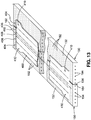
- first mandrel 130 shown is a portion of the first mandrel 130, the pair of lower die web portions 363, and the second mandrel 150 interconnected and aligned with one another via alignment mechanisms 170.
- a portion of the composite laminate 400 made up of a plurality of composite plies 401 and supported by the first mandrel surface 132, the lower die web portions 363, and the second mandrel surface 152.
- the first mandrel surface edge 134 may be in abutting contact with one of the lower die web portions 363.
- the second mandrel surface edge 154 may be in abutting contact with in opposing one of the lower die web portions 363.
- the lower die web portions 363 of the lower forming die 362 may be provided with a lower forming die contour 364 configured complementary to upper forming die contour 354 defined by the upper die web portions 353 of the upper forming die 352. Furthermore, the lower edge of each of the upper die web portions 353 and the upper edge of each of the lower die web portions 363 may optionally be radiused to avoid sharp corners in the composite laminate 400 during forming. However, in some examples, the upper forming die 352 and the lower forming die 362 may be provided with sharp corners.
- the manufacturing system 100 may include a plurality of alignment mechanisms 170 for maintaining alignment between the first mandrel surface 132 and the second mandrel surface 152.
- the first mandrel 130 and second mandrel 150 each include a pin 176 that may be linearly actuated by a linear actuator (not shown).
- Each one of the lower die web portions 363 may include a socket 178 sized and configured to receive the pin 176 of the first mandrel 130 and the second mandrel 150, similar to the arrangement shown in Figures 7-8 and described above.
- the alignment mechanisms 170 may maintain vertical alignment between the first mandrel 130 and the second mandrel 150 in addition to maintaining alignment with the lower die web portions 363 of the lower forming die 362.
- Figure 20 is an end view of the manufacturing system 100 showing the upper forming die 352 vertically lowered into engagement with the composite laminate 400 while the first clamping bar 201 and second clamping bar 203 clamp the composite laminate 400 respectively to the first mandrel surface 132 and the second mandrel surface 152.
- the vacuum source 196 may be deactivated to prevent the application of vacuum pressure 198 between the composite laminate 400 and the first mandrel surface 132 and between the composite laminate 400 and the second mandrel surface 152
- Figure 21 is a magnified view of a portion of the upper forming die 352, the composite laminate 400, the first mandrel 130, the second mandrel 150, and the lower die web portions 363.
- the second mandrel 150 is moved to the open position 164 in which the spacing between the lower die web portions 363 is complementary to the width of the upper die cap portion 355.
- the spacing between the lower die web portions 363 results in the application of laminate clamping pressure 418 on the composite laminate on each of opposing sides of the laminate centerline 402.
- the laminate centerline 402 is laterally aligned with the die centerline 358 of the upper forming die 352 and the lower forming die 362.
- the upper die crossbeam 360 further vertically lowered relative to the position of the upper die crossbeam 360 shown in Figure 20 .
- the downward urging of the composite laminate 400 into the recess 366 between the lower die web portions 363 simultaneously causes the one of the lower die web portions 363 to move laterally outwardly with the first mandrel 130, and causes the opposing one of the lower die web portions 363 to move laterally outwardly with the second mandrel 150.
- the first clamping bar 201 and the second clamping bar 203 continue to clamp the composite laminate 400 respectively against the first mandrel surface 132 and the second mandrel surface 152 while the upper forming die 352 urges the composite laminate 400 downwardly between the opposing pair of lower die web portions 363, and resulting in the generation of lateral tension 416 within the composite laminate 400 on each side of the laminate centerline 402.
- the lateral tension 416 in the composite laminate 400 reduces or prevents the formation of wrinkles or buckles within the composite plies 401 of the composite laminate 400 during forming.
- Figure 23 is a magnified view of a portion of the upper forming die 352, the first mandrel 130, the second mandrel 150, and the lower die web portions 363 showing the composite laminate 400 being urged into the recess between the lower die web portions 363. Also shown is a relatively narrow slipping zone 414 on each side of the laminate centerline 402 within which the composite plies 401 interlaminarly slip relative to one another as the upper forming die 352 is vertically urged downwardly between the lower die web portions 363.
- the slipping zone 414 on each side of the laminate centerline 402 occurs at the intersection or transition (e.g., the radius) of the upper surface of the lower die web portion 363 with the laterally inward-facing surface of the lower die web portion 363.
- the slipping zone 414 on each side of the laminate centerline 402 moves along the web portion 406 on each side of the composite laminate 400 as the upper forming die 352 is gradually urged downwardly between the lower die web portions 363, and which advantageously results in lash forming of the composite laminate 400 in a manner which minimizes wrinkles or buckles that would otherwise occur in the composite laminate 400 if the composite laminate 400 were formed to its final contour all at one time.
- the manufacturing system 100 is configured such that during forming of the composite laminate 400, the die centerline 358 of the upper forming die 352 is maintained in lateral alignment with the die centerline 358 of the lower forming die 362 such that the laminate clamping pressure 418 is equivalent on each side of the laminate centerline 402.
- the laminate clamping pressure 418 on each side of the laminate centerline 402 provides a mechanism for maintaining the composite laminate 400 in fixed position relative to the upper forming die 352 and lower forming die 362 during forming.
- the clamping force provided by the first clamping bar 201 and the second clamping bar 203 allows for sliding movement of the flange portions 404 ( Figure 13 ) of the composite laminate 400 respectively relative to the first mandrel surface 132 and second mandrel surface 152 and respectively relative to the first clamping bar 201 and the second clamping bar 203 as the first mandrel 130 and the second mandrel 150 move laterally outwardly, and which advantageously results in lateral tension 416 in each of laterally opposing sides (e.g., in the flange portions 404) of the composite laminate 400.
- the upper forming die 352 further vertically lowered relative to the position of the upper forming die 352 in Figure 22 and resulting in further laterally outward movement of the first mandrel 130 and second mandrel 150.
- the die flange 356 is in contact with the upper surface of the composite laminate 400 which thereby prevents further downward movement of the upper forming die 352.
- laterally outward movement of the first mandrel 130 and the second mandrel 150 may be passively resisted in order to generate the lateral clamping pressure between the upper forming die 352 and the lower die web portions 363.
- mandrel actuators 174 may be operated in a coordinated manner to generate resistance to laterally outward movement of the first mandrel 130 and second mandrel 150 as a means to generate lateral clamping pressure between the upper forming die 352 and the lower die web portions 363.
- first clamping bar 201 and second clamping bar 203 may apply clamping pressure of the composite laminate 400 against the first mandrel surface 132 and second mandrel surface 152 while the upper forming die 352 urges the web portions 406 ( Figure 22 ) and cap portion 408 ( Figure 22 ) of the composite laminate 400 into the gap 166 between the first mandrel 130 and the second mandrel 150 or into the recess 366 between the lower die web portions 363 during forming of the composite laminate 400, and resulting in lateral tension 416 ( Figure 22 ) being maintained in the flange portions 404 ( Figure 13 ) of the composite laminate 400 on each side of the laminate centerline 402 which thereby reduces or prevents wrinkles or buckles from forming in the composite laminate 400, as mentioned above.
- the first clamping bar 201 and second clamping bar 203 apply clamping pressure at a magnitude that allows the flange portions 404 to slip laterally between the first clamping bar 201 and first mandrel 130 and between the second clamping bar 203 and second mandrel 150 as the first mandrel 130 and second mandrel 150 move laterally outwardly as the upper forming die 352 progressively plunges the web portions 406 and cap portion 408 of the composite laminate 400 into the gap 166 or into the recess 366 between the lower die web portions 363.
- the relative position of the first clamping bar 201 and second clamping bar 203 with respect to the flange portions 404 changes from Figure 20 to Figure 22 to Figure 24 .
- Figure 25 is an end view of the manufacturing system 100 showing the lower die cap portion 365 raised into contact with the cap portion 408 of the composite laminate 400.
- the lower die cap portion 365 may be vertically raised by linear actuator mechanisms (not shown) at each one of the lower die crossbeam 368.
- the lower die cap portion 365 may provide support against clamping pressure applied to the composite laminate 400 by the upper die cap portion 355 of the upper forming die 352.
- the first clamping bar 201 and the second clamping bar 203 may maintain clamping pressure on the composite laminate 400 against the first mandrel surface 132 and the second mandrel surface 152 to generate lateral tension 416 ( Figure 22 ) in the laterally opposite sides of the composite laminate 400.
- FIG. 26 shown is the manufacturing system 100 with the upper forming die 352 moved back to its original position (e.g., Figure 1 ) via vertical movement of the upper die crossbeam 360 using one or more linear actuation mechanisms (not shown).
- the lower forming die 362 may be maintained in position between the first mandrel 130 and the second mandrel 150 to provide support for the composite laminate 400 formed into the final contour.
- Figure 27 shows the composite laminate 400 in the formed condition after removal from the manufacturing system 100.
- the composite laminate 400 in the formed condition may optionally be transferred to additional processing stations (not shown) for further processing such as further debulking and final curing of the composite laminate 400 into a composite stringer.
- additional processing stations not shown
- further processing such as further debulking and final curing of the composite laminate 400 into a composite stringer.
- the manufacturing system is described in the context of manufacturing a composite laminate having a hat-shaped or omega-shaped cross section as shown in Figure 27 , the manufacturing system may be operated in a manner to manufacturing composite laminates having alternative cross-sectional shapes.
- the manufacturing system 100 may be operated in a manner to form a composite laminate having a blade-shaped cross section (not shown) by lowering the lower forming die 362 out of the gap 166 between the first mandrel 130 and the second mandrel 150 in Figure 26 with the upper forming die 352 already removed from the gap 166, and then bringing the first mandrel 130 and the second mandrel 150 back toward each other to pinch together the composite laminate 400 web portions 406 ( Figure 13 ) and cap portion 408 ( Figure 13 ) between the opposing end faces of the first mandrel 130 and the second mandrel 150.
- the manufacturing system 100 may be operated in a manner to form a composite laminate having a I-shaped cross section (not shown) by pinching together only the web portions 406 ( Figure 13 ) and allowing the cap portion 408 of the composite laminate to form into the lower horizontal flange (not shown) of the I-shaped cross section and allowing the flange portions 404 of the composite laminate to form into the upper horizontal flange (not shown) of the I-shaped cross section.
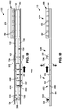
- Figure 28 is a top view of an example of a manufacturing system 100 in which the trimming, laying up, and forming of the composite laminate 400 are respectively and sequentially performed in a layup station 424, a trimming station 426, and a forming station 428.
- Figure 29 is a side view of the manufacturing system 100 of Figure 28 .
- the composite laminate 400 is maintained in fixed position on the first mandrel 130 and/or the second mandrel 150 during the sequential transfer of the first mandrel 130 and second mandrel 150 from the layup station 424 to the trimming station 426 to the forming station 428.
- the manufacturing system 100 of Figures 28-29 may include an interstation transfer mechanism 430 configured to facilitate the transfer of the first mandrel 130 and the second mandrel 150 from the layup station 424 to the trimming station 426 to the forming station 428.
- the interstation transfer mechanism 430 may include a plurality of longitudinal rails 432 extending lengthwise along the first mandrel 130 and the second mandrel 150, as described in greater detail below.
- the manufacturing system 100 of Figures 28-29 may include one or more linear actuation mechanisms (not shown) for transferring the first mandrel 130 and second mandrel 150 between the layup station 424, the trimming station 426, and the forming station 428 while supported on the longitudinal rails 432.
- the manufacturing system 100 may include any one of a variety of alternative arrangements for supporting and transferring the first mandrel 130 and second mandrel 150 between the layup station 424, the trimming station 426, and the forming station 428.
- the above-described laminate securing mechanisms 190 may maintain the composite laminate 400 in fixed position on the first mandrel 130 and/or the second mandrel 150 during the transfer of the first mandrel 130 and the second mandrel 150 from the layup station 424 to the trimming station 426 and from the trimming station 426 to the forming station 428.
- the manufacturing system 100 may include one or more of the above-described vacuum sources 196 fluidly coupled to apertures ( Figure 6 ) formed in the first mandrel surface 132 and the second mandrel surface 152 for fixing the composite laminate 400 to the first mandrel 130 or second mandrel 150 via vacuum pressure 198 (e.g., Figures 5 and 12 ) during the transfer of the first mandrel 130 and second mandrel 150 from the layup station 424 to the trimming station 426, and from the trimming station 426 to the forming station 428.
- vacuum pressure 198 e.g., Figures 5 and 12
- Figure 30 is a top view of an example of the layup station 424 of the manufacturing system 100 of Figures 28-29 .
- Figure 31 is a side view of the layup station 424 and
- Figure 32 is an end view of the layup station 424.
- the layup station 424 of Figures 30-32 may be configured similar to the above-described arrangement shown in Figures 1-8 with the exception that the upper forming die 352, the upper die crossbeam 360, the vertical posts, the lower forming die 362, the lower die crossbeam and the staging area 380 may be omitted, and the interstation transfer mechanism 430 may be included with the first mandrel 130 and the second mandrel 150.
- Figure 32 illustrates a parallel set of longitudinal rails 432 supporting the first mandrel 130 and a parallel set of longitudinal rails 432 supporting the second mandrel 150.
- the layup station 424 may be configured for laying up the composite laminate 400 on the first mandrel 130 and the second mandrel 150 in the closed position 160 defining the continuous mandrel surface 162.
- the lamination head 300 may be supported by any one of a variety of arrangements including, but not limited to, a robotic device, a cantilevered support system, or other arrangements.
- the trimming station 426 of Figures 28-29 may be configured similar or substantially similar to the layup station 424 of Figures 30-32 with the exception that in the trimming station 426, the lamination head 300 may be replaced with a trimming device 330 (e.g., Figure 12 ) such as an ultrasonic cutter or other trimming device 330. As described above, the trimming station 426 may perform the above-described process of trimming the composite laminate 400 on the continuous mandrel surface 162 which is defined by the first mandrel 130 and second mandrel 150 in the closed position 160.
- a trimming device 330 e.g., Figure 12
- the trimming station 426 may perform the above-described process of trimming the composite laminate 400 on the continuous mandrel surface 162 which is defined by the first mandrel 130 and second mandrel 150 in the closed position 160.
- the trimming of the composite laminate 400 may be performed while the composite laminate 400 is maintained in fixed relation to the first mandrel surface 132 and/or the second mandrel surface 152 such as by using vacuum pressure 198 exerted through the apertures 192 formed in the first mandrel surface 132 an/or the second mandrel surface 152.
- Figure 33 is a top view of an example of the forming station 428 of the manufacturing system 100 of Figure 28-29 .
- Figure 34 is a side view of the forming station 428 and
- Figure 35 is an end view of the forming station 428 of Figure 33 showing the longitudinal rails 432 for supporting the first mandrel 130 and the second mandrel 150 on the respective mandrel supports 118.
- the forming station 428 of Figures 33-35 may be configured similar to the above-described arrangement shown in Figures 1-8 and 16-26 with the exception of the addition of the interstation transfer mechanism 430 (e.g., longitudinal rails 432) and the omission of the gantry 104 and the staging area 380.
- the interstation transfer mechanism 430 e.g., longitudinal rails 432
- the forming station 428 includes the upper forming die 352 and the lower forming die 362 for forming the composite laminate 400 when supported on the first mandrel 130 and the second mandrel 150 in the open position 164 after the composite laminate 400 has been trimmed on the continuous mandrel surface 162 defined by the first mandrel 130 and the second mandrel 150 in the closed position 160.
- the manufacturing system 100 may be provided in any one of a variety of alternative sizes, shapes and configurations for supporting any one or more of the above-described components including, but not limited to, the first mandrel 130, the second mandrel 150, the lamination head 300, the trimming device 330, the upper forming die 352, the lower forming die 362, the laminate releasing mechanisms 220, the alignment mechanisms 170, and the laminate securing mechanisms 190 including the pinch mechanisms 200, 202.
- the manufacturing system 100 may include one or more lamination heads 300 supported by one or more robotic devices (not shown) configured to position the lamination head 300 during layup of the composite laminate 400.
- the manufacturing system 100 may include a plurality of trimming devices 330 (not shown) that are fixedly supported by a corresponding series of support members (not shown) arranged at spaced intervals along the lengthwise direction of the first mandrel 130 and second mandrel 150.
- the upper forming die 352 may be vertically movable by a series of forming die actuators (not shown) supported by a corresponding series of cantilevered beams (not shown) coupled to the base member 102 and arranged at spaced intervals along a lengthwise direction of the upper forming die 352.
- the lower forming die 362 may be vertically raised into the gap 166 between the first mandrel 130 and the second mandrel 150, the lower forming die 362 may be horizontally translated into the gap 166 along a direction parallel to the lengthwise direction of the first mandrel 130 and second mandrel 150.
- the pinch mechanisms 200, 202 may be passive mechanisms coupled to the vertically movable upper die crossbeam 360
- the pinch mechanisms 200, 202 may be actively controlled electro-mechanical clamping actuators (not shown) fixedly mounted to the manufacturing system 100.
- the manufacturing system 100 may be configured for laying up, trimming, and forming any one of a variety of different sizes, shapes, and configurations of composite laminates, and is not limited to the laying up, trimming and forming a composite laminate into a composite stringer.
- Step 502 of the method 500 includes positioning the second mandrel surface edge 154 of a second mandrel 150 in the closed position 160 in side-by-side abutting contact with the first mandrel surface edge 134 of a first mandrel 130 to form a continuous mandrel surface 162 collectively defined by the first mandrel surface 132 and the second mandrel surface 152.
- a plurality of mandrel actuators 174 may move the second mandrel 150 toward the first mandrel 130 until the second mandrel 150 edge is in abutting contact with the first mandrel 130 edge to thereby form the continuous mandrel surface 162.
- the method may further include maintaining alignment between the first mandrel 130 and the second mandrel 150 during the layup, trimming, and/or forming of the composite laminate 400. Vertical alignment may be maintained between the first mandrel surface 132 and the second mandrel surface 152 via a plurality of alignment mechanisms 170 such as the pin 176 and socket 178 arrangement shown in Figures 7-8 and/or Figure 19 and described above.
- Step 504 of the method 500 includes providing a composite laminate 400 on the continuous mandrel surface 162 while securing the composite laminate 400 in fixed position to the first mandrel surface 132 and/or the second mandrel surface 152.
- the composite laminate 400 may be laid up at a remote location (not shown) and then transferred onto the continuous mandrel surface 162.
- the step of providing the composite laminate 400 may include laying up or applying layup material 310 over the continuous mandrel surface 162 using a lamination head 300 as shown in Figures 4-6 and described above.
- Step 504 may further include securing the composite laminate 400 to the first mandrel surface 132 and/or the second mandrel surface 152 while forming the composite laminate 400.
- the method may include securing the composite laminate 400 to the first mandrel surface 132 and/or the second mandrel surface 152 after the composite laminate 400 has been provided on the continuous mandrel surface 162.
- the method may include using vacuum pressure 198 to secure the composite laminate 400 to the first mandrel surface 132 and/or the second mandrel surface 152.
- the vacuum pressure 198 may be applied to the composite laminate 400 through a plurality of apertures 192 ( Figure 6 ) that may be formed in the first mandrel surface 132 and/or the second mandrel surface 152.
- a vacuum source 196 such as a vacuum pump may be activated for generating the vacuum pressure 198 at the apertures 192 for securing the composite laminate 400 to the first mandrel 130 and/or the second mandrel 150.
- the method may include mechanically clamping the composite laminate 400 to the first mandrel surface 132 and/or the second mandrel surface 152.
- Mechanical clamping may be performed using any one of a variety of different configurations of clamping devices. For example, mechanical clamping may be performed using the pinch mechanisms 200, 202 described above and/or illustrated in Figures 17-18 and 20-21 .
- Step 506 of the method 500 includes trimming the composite laminate 400 on the continuous mandrel surface 162 as shown in Figure 12 .
- Trimming of the composite laminate 400 may be performed using a trimming device 330 such as an ultrasonic cutter, a laser cutter, a mechanical blade, and/or other trimming devices 330.
- trimming the composite laminate 400 on the continuous mandrel surface 162 may improve the accuracy of trimming due to the entirety of the composite laminate 400 being supported during the trimming operation. Trimming may be performed prior to movement of the second mandrel 150 from the closed position 160 ( Figure 12 ) to the open position 164 ( Figure 16-18 , 20 , 22 , and 24-26 ), as described below.
- the trimming of the composite laminate 400 may be performed after forming such as when the composite laminate 400 is supported by the first mandrel 130 and second mandrel 150 and optionally additionally supported by the lower die web portions 363 as shown in Figure 26 .
- Step 508 of the method 500 includes releasing, using one or more laminate releasing mechanisms 220, the composite laminate 400 from the second mandrel surface 152 after trimming the composite laminate 400 and prior to moving the second mandrel 150 from the closed position 160 to the open position 164.
- releasing the composite laminate 400 from the second mandrel surface 152 may be achieved by discharging air from a plurality of apertures 192 ( Figure 6 ) formed in the second mandrel surface 152.
- the apertures 192 may be fluidly coupled to a positive air pressure source 222 via a plurality of fluid conduits 194 that may be incorporated into the second mandrel 150. Activation of the positive air pressure source 222 results in positive air pressure 224 ( Figure 16 ) at the apertures 192 which forces the composite laminate 400 away from the second mandrel surface 152 to allow movement of the second mandrel 150.
- the composite laminate 400 may continue to be secured to the first mandrel surface 132 via the laminate securing mechanisms 190.
- a plurality of first pinch mechanisms 200 may at least partially clamp, via a first clamping bar 201, the composite laminate 400 to the first mandrel surface 132 prior to and during movement of the second mandrel 150 to thereby maintain the composite laminate 400 in fixed position on the first mandrel surface 132 while the second mandrel 150 moves relative to the portion of the composite laminate 400 overlying the transiting mandrel surface.
- the first clamping bar 201 of the first pinch mechanisms 200 may clamp the composite laminate 400 to the first mandrel surface 132 as a result of lowering the upper die crossbeam 360 as shown in Figure 16 .
- the composite laminate 400 may be secured to the first mandrel surface 132 as a result of the continued application of vacuum pressure 198 to the apertures 192 in the first mandrel surface 132.
- Step 510 of the method 500 includes translating the second mandrel 150 along a direction transverse to or perpendicular to the first mandrel surface edge 134 from the closed position 160 ( Figure 12 ) toward the open position 164 to define a gap 166 ( Figure 17 ) between the first mandrel surface edge 134 and the second mandrel surface edge 154 while continuing to secure the composite laminate 400 to the first mandrel surface 132 via the laminate securing mechanisms 190 (e.g., vacuum pressure 198, pinch mechanisms 202) and while continuing to discharge positive air pressure 224 from apertures 192 in the second mandrel surface 152. Movement of the second mandrel 150 may be effectuated by the mandrel actuators 174.
- the second mandrel 150 may be supported on the above-described lateral rails 172 ( Figures 16-17 ) which may facilitate sliding movement of the second mandrel 150. Once the second mandrel 150 is moved into an open position 164 in which the width of the gap 166 ( Figure 17 ) is complementary to the width of the upper forming die 352 and/or the lower die web portions 363, a plurality of laminate securing mechanisms 190 may be activated for securing the composite laminate 400 to the second mandrel surface 152.
- the upper die crossbeam 360 may be lowered into a position in which the second clamping bar 203 of the second pinch mechanisms 202 at least partially clamp the composite laminate 400 to the second mandrel surface 152 while the first clamping bar 201 of the first pinch mechanisms 200 continue to at least partially clamp the composite laminate 400 to the first mandrel surface 132.
- vacuum pressure 198 may assist in securing the composite laminate 400 to first mandrel surface 132 and the second mandrel surface 152.
- Step 512 of the method 500 includes forming the composite laminate 400 into a laminate contour 412 ( Figures 26-27 ) by urging the composite laminate 400 into the gap 166.
- the method may include translating the upper forming die 352 downwardly into contact with the composite laminate 400 and forcing the composite laminate 400 into the gap 166 between the first mandrel 130 and second mandrel 150 while the laminate securing mechanisms 190 (e.g., the first clamping bar 201 and the second clamping bar 203) clamp the composite laminate 400 to the first mandrel surface 132 and the second mandrel surface 152.
- the laminate securing mechanisms 190 e.g., the first clamping bar 201 and the second clamping bar 203
- the method may include translating the lower die web portions 363 upwardly into the gap 166 between the first mandrel 130 and the second mandrel 150.
- the lower forming die 362 may support the composite laminate 400 against forming pressure applied by the upper forming die 352. If the manufacturing system 100 includes the lower forming die 362, the method may include translating the upper forming die 352 to urge the composite laminate 400 into the recess 366 between the lower die web portions 363 while the laminate securing mechanisms 190 continue to clamp the composite laminate 400 to the first mandrel surface 132 and the second mandrel surface 152.
- vertical movement of the upper forming die 352 may be facilitated by vertically lowering the upper die crossbeam 360 via linear actuators (not shown).
- Vertical movement of the lower forming die 362 may be facilitated by vertically raising the lower die crossbeam 360 via linear actuators (not shown).
- the method may additionally include maintaining alignment between the first mandrel surface 132 and the second mandrel surface 152 using one or more alignment mechanisms 170 during the process of forming the composite laminate 400.
- the method may include linearly actuating the pins 176 of the first mandrel 130 and second mandrel 150 into engagement with corresponding sockets 178 formed in the laterally opposite sides of the lower die web portions 363 ( Figure 19 ) as a means to maintain vertical alignment between the first mandrel surface 132, the lower die web portions 363, and the second mandrel surface 152.
- the laminate securing mechanisms 190 may continue to at least partially clamp the laterally opposing sides (e.g., the flange portions 404) of the composite laminate 400 respectively to the first mandrel surface 132 and the second mandrel surface 152.
- the spacing between the lower die web portions 363 is complementary to the width of the upper die cap portion 355 which results in the application of laminate clamping pressure 418 on the composite laminate 400 on each of opposing sides of the laminate centerline 402.
- the laminate centerline 402 is laterally aligned with the die centerline 358 of the upper forming die 352 and the lower forming die 362 such that the laminate clamping pressure 418 is simultaneously applied in equal magnitude on each of opposing sides of the laminate centerline 402.
- the laminate clamping pressure 418 maintains the laminate centerline 402 in alignment with the die centerline 358 during forming of the composite laminate 400.
- FIG. 22-23 shown is the further progression of the plunging of the upper forming die 352 into the recess 366 between the lower die web portions 363 which causes laterally outward movement of the pair of lower die web portions 363 and the first mandrel 130 and the second mandrel.
- Clamping pressure may be continuously applied by the first clamping bar 201 and the second clamping bar 203 while the upper forming die 352 urges the composite laminate 400 into the recess 366 between the lower die web portions 363, and resulting in the flange portions 404 slipping between the first clamping bar 201 and first mandrel 130 and between the second clamping bar 203 and second mandrel 150 as the first mandrel 130 and second mandrel 150 move laterally outwardly.
- the combination of laminate clamping pressure 418 between the upper forming die 352 and lower die web portions 363 in combination with the clamping force applied by the first clamping bar 201 and the second clamping bar 203 results in lateral tension 416 on the composite laminate 400 on each of opposing sides of the laminate centerline 402. As mentioned above, the lateral tension 416 in the composite laminate 400 reduces or prevents wrinkling or buckling of the composite plies 401 during forming of the composite laminate 400.
- the upper forming die 352 lowered into its final position in which the die flange 356 is in contact with the upper surface of the composite laminate 400.
- the lower forming die 362 may include a lower die cap portion 365 which may be raised into contact with the cap portion 408 of the composite laminate 400 to provide support against clamping pressure applied on the composite laminate 400 by the upper die cap portion 355 of the upper forming die 352.
- the method may include vertically translating the upper forming die 352 back to its original position (e.g., Figure 1 ).
- the method may include removing the formed composite laminate 400 from the manufacturing system 100 for optional further processing such as debulking and/or final curing.
- the method of manufacturing the composite laminate 400 may be performed on a manufacturing system 100 having a layup station 424, a trimming station 426, and a forming station 428 described above.
- the method may include transferring the first mandrel 130 and the second mandrel from the layup station 424 to the trimming station 426 after laying up the composite laminate 400, and transferring the composite laminate 400 from the trimming station 426 to the forming station 428 after trimming of the composite laminate 400.
- the transfer of the first mandrel 130 and second mandrel 150 between the layup station 424, the trimming station 426 and the forming station 428 may be performed using an interstation transfer mechanism 430 such as the above-described longitudinal rails 432 and one or more linear actuation mechanisms (not shown).
- the method may include maintaining the composite laminate 400 in fixed position on the first mandrel 130 and/or the second mandrel 150.
- Maintaining the composite laminate 400 in fixed position on the first mandrel 130 and/or the second mandrel 150 may be performed using the above-described laminate securing mechanisms 190 for applying vacuum pressure 198 to the composite laminate 400 via apertures 192 formed in the first mandrel surface 132 and/or the second mandrel surface 152.
- the composite laminate 400 may be secured on the first mandrel 130 and/or the second mandrel 150 by using one or more mechanical clamping devices (not shown).
- Step 504 of providing a composite laminate 400 on the continuous mandrel surface 162 may include laying up the composite laminate 400 at the layup station 424.
- the layup of the composite laminate 400 may be performed on the continuous mandrel surface 162 collectively defined by the first mandrel 130 and the second mandrel 150 in the closed position 160.
- the layup station 424 may be configured similar to the arrangement shown in Figures 30-32 and may include a lamination head 300 supported on a gantry 104 as described above with regard to Figures 4-5 , although the lamination head 300 may be supported by any number of devices including a robotic device, a cantilevered support, or other structural arrangements.
- Step 506 of trimming the composite laminate 400 may be performed on the continuous mandrel surface 162 at the trimming station 426 after laying up the composite laminate 400 on the same continuous mandrel surface 162 at the layup station 424 and then transferring the composite laminate 400 from the layup station 424 to the trimming station 426 via the interstation transfer mechanism 430 such as the above-described longitudinal rails 432 using one or more linear actuation mechanisms (not shown).
- the composite laminate 400 may be trimmed after forming such as when supported by the first mandrel 130 and second mandrel 150 and by the lower die web portions 363 as shown in Figure 26 .
- Trimming of the composite laminate 400 may be performed using a trimming device 330 such as the ultrasonic cutter illustrated in Figure 12 .
- the method may include transferring the first mandrel 130 and second mandrel 150 from the trimming station 426 to the forming station 428 via the above-described interstation transfer mechanism 430 (e.g., longitudinal rails 432 and linear actuation mechanisms).
- Step 512 of forming the composite laminate 400 may be performed at the forming station 428 with the first mandrel 130 and the second mandrel 150 in the open position 164 as described above and illustrated in Figures 16-26 .
- the composite laminate 400 may be removed from the first mandrel 130 and second mandrel 150 and transferred to another location (not shown) such as to a holding station (not shown) or to a subsequent manufacturing (station) for further processing such as debulking and/or final curing.
- the composite laminate 400 may be manually lifted off of the first mandrel 130 and the second mandrel 150, or a vacuum lifting device (not shown) and overhead crane or gantry (not shown) may be used to lift the composite laminate 400 off of the first mandrel 130 and the second mandrel 150 and transfer the composite laminate 400 to another location (not shown).
- a vacuum lifting device not shown
- overhead crane or gantry not shown
- the first mandrel 130 and the second mandrel 150 may be recirculated back to the layup station 424 for layup of another composite laminate 400 on the continuous mandrel surface 162 defined by the first mandrel 130 and second mandrel 150 in the closed position 160.
- Recirculation of the first mandrel 130 and second mandrel 150 from the forming station 428 back to the layup station 424 may be performed using a mandrel recirculation system 434.
- the first mandrel 130 and second mandrel 150 may be transferred from the forming station 428 back to the layup station 424 using a conveyor system 436 which may include a pair of laterally-oriented conveyor belts (not shown) respectively positioned at opposing ends of the forming station 428 and configured to transfer the first mandrel 130 and second mandrel 150 from the forming station 428 onto a longitudinally-oriented conveyor belt (not shown) extending from the forming station 428 to the layup station 424.
- the manufacturing system 100 may include another pair of laterally-oriented conveyor belts respectively located at opposing ends of the layup station 424 for transferring the first mandrel 130 and second mandrel 150 from the longitudinally-oriented conveyor belt to the layup station 424.
- the mandrel recirculation system 434 may include additional hardware such as one or more robotic devices for picking up and placing the first mandrel 130 on and off the conveyor system 436.
- FIG. 37 and 38 shown in Figures 37 and 38 is a top view and a side view respectively of a further example of a manufacturing system 100 in which the layup, trimming, and forming of the composite laminate 400 ( Figure 39 ) are respectively and sequentially performed in a layup station 424, a trimming station 426, and a forming station 428.
- the layup station 424 has a layup mandrel set 425 including a first mandrel 130 and a second mandrel 150 configured for supporting the composite laminate 400 during the laying up of the composite laminate 400 via one or more lamination heads 300.
- the trimming station 426 has a trimming mandrel set 427 including a first mandrel 130 and a second mandrel 150 configured for supporting the composite laminate 400 during trimming of the composite laminate 400 via a trimming device 330.
- the forming station 428 has a forming mandrel set 429 including a first mandrel 130 and a second mandrel 150 configured for supporting the composite laminate 400 during forming via an upper forming die 352 and a lower forming die 362 at the forming station 428.
- the interstation transfer mechanism 430 is comprised of an upper clamping mechanism 450 and a lower clamping mechanism 480 configured to clamp onto the composite laminate 400 and transfer the composite laminate 400 between the stations while the first mandrel 130 and the second mandrel 150 at each station remain stationary.
- the upper forming die 352 and the lower forming die 362 may function respectively as the upper clamping mechanism 450 and the lower clamping mechanism 480 for engaging (e.g., clamping onto) and transferring the composite laminate 400 between the stations.
- the upper forming die 352 and/or the lower forming die 362 may maintain the composite laminate 400 in alignment with the stations during the transfer.
- the upper clamping mechanism 450 e.g., the upper forming die 352 and/or the lower clamping mechanism 480 (e.g., the lower forming die 362) are configured to engage the composite laminate 400.
- the upper clamping mechanism 450 and the lower clamping mechanism 480 may be configured to clamp onto the cap portion 408 (e.g., Figures 44 and 58 ) of the composite laminate 400 which spans the gap 166 (e.g., Figures 43 and 57 ) between the first mandrel 130 and second mandrel 150 when in the open position 164 ( Figure 43 ).
- the lower clamping mechanism 480 may be configured to engage the cap portion 408 via the application of vacuum pressure 198 drawn through apertures 192 formed in the lower clamping mechanism 480.
- the lower clamping mechanism 480 e.g., the lower die cap portion 365 of the lower forming die 362 may move within and along a lengthwise direction of the gap 166.
- positive air pressure 224 may be discharged from a plurality of apertures 192 ( Figure 6 ) formed in the first mandrel 130 and/or second mandrel 150 to float the composite laminate 400 over the first mandrel 130 and second mandrel 150 at each station during the transferring of the composite laminate 400.
- the ability to use the upper forming die 352 and/or the lower forming die 362 for transferring the composite laminate 400 between stations eliminates the need for external equipment such as a separate pick-and-place system (not shown) for transferring the composite laminate 400.
- the layup station 424 may include a gantry 104 supporting one or more lamination heads 300.
- the gantry 104 may be configured similar to the above-described arrangement shown in Figures 4-5 .
- the gantry 104 may be movable along the gantry tracks 116 ( Figure 39 ) that may be included with the base members 102 of the manufacturing system 100.
- the gantry tracks 116 may extend continuously along the layup station 424, the trimming station 426 and the forming station 428 to allow the gantry 104 to be temporarily positioned at the trimming station 426 and/or at the forming station 428 (e.g., Figures 40-41 , 45 ) to avoid interfering with the movement of the upper forming die 352 and lower forming die 362 when transferring the composite laminate 400 between the stations.
- the trimming station 426 may also include a gantry 104 which may support a trimming device 330 for trimming the composite laminate 400 after being transferred from the layup station 424. Similar to the above-described arrangement of the gantry 104 supporting the lamination head 300, the gantry 104 supporting the trimming device 330 may also be movable along the above-described gantry tracks 116 to allow the trimming device 330 to be temporarily positioned at the layup station 424 and/or forming station 428 to avoid interfering with the movement of the upper clamping mechanism 450 and lower clamping mechanism 480 when transferring the composite laminate 400 between stations.
- Figure 39 is a sectional view of the layup station 424 showing an example of a lamination head 300 laying up the composite laminate 400 on the first mandrel 130 and the second mandrel 150 in the closed position 160.
- the first mandrel 130 and/or the second mandrel 150 may include the above-mentioned apertures 192 for drawing a vacuum pressure 198 on the composite laminate 400 to secure the composite laminate 400 in position in the same manner as described above with regard to Figures 5-6 .
- positive air pressure 224 ( Figure 43 ) may be discharged from the apertures 192 for releasing the composite laminate 400 from the first mandrel surface 132 ( Figure 43 ) and/or the second mandrel surface 152 ( Figure 43 ) in the same manner described above with regard to Figure 16 .
- the lamination head 300 and the supporting hardware may be configured similar to the above-described arrangement shown in Figures 5-8 .
- the lamination head 300 may be supported on a gantry crossbeam 106 of a gantry 104.
- the opposing ends of the gantry crossbeam 106 may be coupled to a pair of beam supports 114 which may be movable along a pair of gantry tracks 116 respectively mounted on the pair of base members 102.
- the base members 102 may include additional gantry tracks 116 to facilitate movement of the upper forming die 352 ( Figures 37-38 ) and lower forming die 362 ( Figures 37-38 ) between stations, as described below.
- Figure 40 is a side view of the manufacturing system 100 showing the upper forming die 352 and the lower forming die 362 moving from the forming station 428 toward the layup station 424.
- the upper forming die 352 may be supported by a plurality of upper die crossbeams 360 ( Figure 42 ) arranged at spaced intervals along a lengthwise direction of the manufacturing system 100.
- Each one of the upper die crossbeams 360 may be coupled to a pair of posts 350 ( Figure 42 ) extending upwardly respectively from the base members 102 on laterally opposite sides of the manufacturing system 100.
- the plurality of posts 350 are movable in unison along the gantry tracks 116 via one or more linear actuation mechanisms (not shown).
- Figure 40 the gantry 104 of the trimming device 330 and the gantry 104 of the lamination head 300 are shown temporarily placed in the forming station 428 to avoid interfering with the movement of the upper forming die 352 and lower forming die 362 in transferring the composite laminate 400 ( Figure 39 ) from the layup station 424 to the trimming station 426.
- Figure 41 shows the upper forming die 352 and lower forming die 362 at the layup station 424 in preparation for clamping onto the composite laminate 400.
- Figure 42 is a sectional view of the layup station 424 showing the initial position of the upper forming die 352 and lower die web portions 363 of the lower forming die 362 prior to the upper forming die 352 and the lower die cap portion 365 ( Figure 44 ) engaging or clamping onto the composite laminate 400.
- the upper forming die 352 and the lower forming die 362 may be configured similar or substantially similar to the arrangement shown in Figure 5 with the exception that in Figure 42 , the posts 350 of the upper forming die 352 are supported on the gantry tracks 116.
- the gantry tracks 116 for the upper forming die 352, the lower forming die 362, and the gantries 104 may be continuous from the layup station 424 to the forming station 428.
- Figure 43 shows the upper forming die 352 and the lower forming die 362 at the layup station 424.
- the upper forming die 352 is shown being lowered by the gantry crossbeam 106 toward the composite laminate 400.
- the pair of lower die web portions 363 are shown translating away from each other.
- the second mandrel 150 being translated away from the first mandrel 130 into the open position 164 to define the gap 166.
- the first mandrel 130 and the second mandrel 150 may be configured similar or substantially similar to the above-described arrangement shown in Figures 1-3 .
- first mandrel 130 and the second mandrel 150 may each be laterally translated along lateral rails 172 ( Figure 43 ) coupling the first mandrel 130 and second mandrel 150 respectively to the base members 102.
- Translation of the first mandrel 130 and second mandrel 150 may be facilitated by one or more mandrel actuators 174 located at spaced intervals along the lengthwise direction of each mandrel.
- positive air pressure 224 may be discharged from the apertures 192 in the second mandrel surface 152 to urge the composite laminate 400 away from the second mandrel surface 152 in the same manner described above with regard to Figure 16 .
- Vacuum pressure 198 may be drawn on the first mandrel surface 132 to fixedly secure the position of the composite laminate 400 on the first mandrel 130.
- the application of vacuum pressure 198 between the composite laminate 400 and the first mandrel 130 and/or second mandrel 150 may maintain the laminate centerline 402 in lateral alignment with the die centerline 358 of the upper forming die 352 and the die centerline 358 of the lower forming die 362 which may improve the accuracy with which the composite laminate 400 is trimmed and/or formed.
- Figure 44 shows the upper forming die 352 in contact with a top side of the cap portion 408 of the composite laminate 400.
- the upper forming die 352 may be configured as a unitary structure such as a bar member having a length at least as long as the composite laminate 400.
- the upper forming die 352 may be provided as a series of end-to-end bar segments.
- the lower die cap portion 365 of the lower forming die 362 is shown extended vertically upwardly through the gap 166 and into contact with a bottom side of the cap portion 408 of the composite laminate 400.
- the lower die cap portion 365 may be configured as a unitary bar member or as a series of end-to-end bar segments having a total length that is at least as long as the composite laminate 400.
- the upper forming die 352 and lower die cap portion 365 (of the lower forming die 362) may apply light clamping pressure on the composite laminate 400 to allow transferring of the composite laminate 400 without locally indenting the composite laminate 400.
- vacuum pressure 198 may be applied to apertures 192 (not shown) formed in the upper forming die 352 and/or in the lower die cap portion 365 to fixedly secure the composite laminate 400 to the upper forming die 352 and/or lower die cap portion 365 during transferring of the composite laminate 400 between stations.
- vacuum pressure 198 may be applied to apertures 192 and the lower die cap portion 365 to secure (without the upper forming die 352) the composite laminate 400 to the lower die cap portion 365 for transferring the composite laminate 400 between stations.
- Vacuum pressure 198 ( Figure 42 ) on the first mandrel 130 or second mandrel 150 may be deactivated prior to initiating the transfer of the composite laminate 400 from the layup station 424.
- Figure 45 is a side view of the manufacturing system 100 showing the upper forming die 352 and the lower forming die 362 moving the composite laminate 400 from the layup station 424 toward the trimming station 426.
- the posts 350 ( Figure 43 ) of the upper forming die 352 and the lower die crossbeam 368 ( Figure 43 ) each move along the gantry tracks 116 ( Figure 43 ) which may extend continuously from the layup station 424 to forming station 428.
- positive air pressure 224 (e.g., 43) may be discharged from the apertures 192 in the first mandrel 130 and second mandrel 150 at each station to allow the composite laminate 400 to float on a thin cushion of air over the first mandrel 130 and second mandrel at each station.
- Figure 46 shows the upper forming die 352 and the lower forming die 362 at the trimming station 426.
- the gantry 104 for the lamination head 300 is shown moved from the forming station 428 back to the layup station 424.
- the gantry 104 for the trimming device 330 is shown temporarily positioned in the forming station 428.
- Figure 47 is a sectional view of the trimming station 426 showing the upper forming die 352 and the lower forming die 362 retracted away from the composite laminate 400 and showing the trimming device 330 moved back into the trimming station 426 for trimming the composite laminate 400 on the continuous mandrel surface 162 defined by the first mandrel 130 and second mandrel 150.
- vacuum pressure 198 may be applied to the first mandrel 130 and/or the second mandrel 150 as shown in Figure 47 to fixedly secure the composite laminate 400 in position on the continuous mandrel surface 162 during trimming operations.
- another composite laminate (not shown) may be laid up at the layup station 424 and/or another composite laminate (not shown) may be formed at the forming station 428.
- the trimming device 330 may be moved to the layup station 424, and the upper forming die 352 and lower die cap portion 365 may be moved into contact with the composite laminate 400 in the same manner as described above with regard to Figures 42-44 .
- Figure 48 is a side view of the manufacturing system 100 showing the gantry 104 for the trimming device 330 temporarily positioned in the layup station 424. Also shown is the upper forming die 352 and lower forming die 362 transferring the composite laminate 400 from the trimming station 426 toward the forming station 428. Figure 49 shows the upper forming die 352 and lower forming die 362 at the forming station 428 in preparation for forming the composite laminate 400. During forming of the composite laminate 400 at the forming station 428, another composite laminate (not shown) may be laid up at the layup station 424 and/or another composite laminate (not shown) may be trimmed at the trimming station 426.
- Figure 50 is a sectional view of the forming station 428 showing the upper forming die 352 and the lower die cap portion 365 retracted away from the composite laminate 400.
- Vacuum pressure 198 may be applied to the first mandrel surface 132 for securing the composite laminate 400 in position on the first mandrel 130 prior to retracting the upper forming die 352 and lower die cap portion 365 away from the composite laminate 400.
- the first clamping bar 201 may clamp the composite laminate 400 to the first mandrel surface 132 while the second mandrel 150 translates laterally away from the first mandrel 130.
- Positive air pressure 224 may be discharged from the apertures 192 in the second mandrel surface 152 to urge the composite laminate 400 away from the second mandrel surface 152 to facilitate lateral translation of the second mandrel 150 away from the first mandrel 130 toward the open position 164 ( Figure 51 ).
- Figure 51 is a sectional view of the forming station 428 showing the upper forming die 352 after forming the composite laminate 400 against the lower die web portions 363 and the lower die cap portion 365 positioned within the gap 166 between the first mandrel 130 and the second mandrel 150 during a forming process similar to the process described above and shown in Figures 17-26 .
- the first clamping bar 201 and the second clamping bar 203 may respectively clamp the opposing flange portions 404 of the composite laminate 400 respectively to the first mandrel 130 and the second mandrel 150 to generate lateral tension 416 ( Figures 20 and 22 ) in the composite laminate 400 as the upper forming die 352 urges the composite laminate 400 against the lower forming die 352 during the forming process.
- vacuum pressure 198 may be applied to the apertures 192 in the first mandrel 130 and second mandrel 150 to prevent the composite laminate 400 from lifting off of the first mandrel 130 and second mandrel 150 as the upper forming die 352 is vertically retracted.
- the composite laminate 400 may be formed as shown in Figure 27 or in any one a variety of alternative cross-sectional shapes dictated by the shape and configuration of the upper forming die 352 and the lower forming die 362.
- the upper forming die 352 and/or the lower forming die 362 may be configured to transfer the composite laminate 400 from the forming station 428 to a holding station (not shown) or to any one of a variety of subsequent manufacturing stations (not shown) such as for consolidating and/or curing the composite laminate 400.
- the method may include transferring the composite laminate 400 between stations such as between the layup station 424, the trimming station 426, and the forming station 428 shown in Figures 37-38 .
- transferring the composite laminate 400 between stations may include engaging, using the upper clamping mechanism 450 and/or the lower clamping mechanism 480, a portion of the composite laminate 400 spanning the gap 166 between the first mandrel 130 and the second mandrel 150 in the open position 164.
- the upper clamping mechanism 450 may be the upper forming die 352, and the lower clamping mechanism 480 may be the lower die cap portion 365 of the lower forming die 362 as described above.
- the upper clamping mechanism (upper forming die 352) and the lower clamping mechanism 480 (lower die cap portion 365) may clamp onto the composite laminate 400 prior to transferring between stations.
- the method may include applying or drawing vacuum pressure 198 on apertures 192 in the lower die cap portion 365 for securing (e.g., without the use of the upper clamping mechanism 450) the composite laminate 400 to the lower clamping mechanism 480 for transferring the composite laminate 400 between stations.
- the method may include forcing air through the apertures 192 in the first mandrel surface 132 and second mandrel surface 152 at each station for floating the composite laminate 400 over the first mandrel 130 and second mandrel 150 at each station during the transferring of the composite laminate 400.
- the method may include maintaining the composite laminate 400 in alignment with the stations during the transfer while the first mandrel 130 and the second mandrel 150 at each station are stationary.
- the alignment of the composite laminate 400 may be maintained by the use of vacuum pressure 198 on the first mandrel 130, second mandrel 150, upper forming die 352, and/or lower die cap portion 365 during the release and clamping of the composite laminate 400 at one or more of the stations.
- the method 500 may optionally include using the upper forming die 352 and lower die cap portion 365 of the lower forming die 362 to transfer the composite laminate 400 from the forming station 428 to a dismount station (not shown) or a holding station (not shown) or to a subsequent manufacturing station (not shown) as mentioned above.
- the upper forming die 352 and lower die cap portion 365 may clamp onto the cap portion 408 of the composite laminate 400 in a manner similar to the clamping process shown in Figure 44 .
- the first and second clamping bar 201, 203 Prior to moving the composite laminate 400 to a holding station (not shown) or subsequent manufacturing station (not shown), the first and second clamping bar 201, 203 ( Figure 51 ) may be upwardly retracted away from the composite laminate 400, and the lower die web portions 363 ( Figure 51 ) may be downwardly retracted away from the composite laminate 400.
- FIG. 52 and 53 shown in Figures 52 and 53 is a top view and a side view respectively of a further example of a manufacturing system 100 in which the layup, trimming, and forming of the composite laminate 400 ( Figure 54 ) are respectively and sequentially performed in a layup station 424, a trimming station, and a forming station 428.
- the layup station 424 has a layup mandrel set 425 including a first mandrel 130 and a second mandrel 150 configured for supporting the composite laminate 400 during the laying up of the composite laminate 400.
- the trimming station 426 includes a trimming mandrel set 427 having a first mandrel 130 and a second mandrel 150 configured to receive the composite laminate 400 from the layup station 424, and supporting the composite laminate 400 during trimming.
- the forming station 428 has a forming mandrel set 429 including a first mandrel 130 and a second mandrel 150 configured to receive the composite laminate 400 from the trimming station 426.
- the forming station 428 is configured to laterally translate the first mandrel 130 and second mandrel 150 into a forming stand 490 having a plurality of forming heads 492 for forming the composite laminate 400.
- the manufacturing system 100 of Figures 52-69 includes a dedicated upper clamping mechanism 450 and a dedicated lower clamping mechanism 480, as distinguished from the manufacturing system 100 shown in Figure 37-51 in which the upper forming die 352 and the lower die cap portion 365 of the lower forming die 362 are respectively used as the upper clamping mechanism 450 and lower clamping mechanism 480 for transferring the composite laminate 400 between stations.
- the upper clamping mechanism 450 is configured as a plurality of upper clamp modules 452.
- the lower clamping mechanism 480 is configured as a lower clamp member 484 supported on one or more lower crossmembers 482.
- the upper clamping mechanism 450 and/or the lower clamping mechanism 480 are configured to engage the composite laminate 400, and transfer the composite laminate 400 from the layup station 424 to the trimming station 426 and from the trimming station 426 to the forming station 428.
- the manufacturing system 100 may include a pair of base members 102 extending along and between the layup station 424, the trimming station 426, and the forming station 428.
- the layup station 424 may include at least one lamination head 300 for laying up the composite laminate 400 on the layup mandrel set 425.
- the lamination head 300 may be supported on a gantry 104 configured to move along the length of the layup station 424.
- the layup station 424 may include a staging area 380 for temporarily storing the lamination head 300 during the engagement of the upper clamping mechanism 450 and lower clamping mechanism 480 to the composite laminate 400 for transferring to the trimming station 426.
- the trimming station 426 may include a trimming device 330 provided in any one of the above-described configurations.
- the trimming device 330 may be supported on a gantry 104 configured to move along the length of the trimming station 426 similar to the movement of the gantry 1044 for moving the lamination head 300 along the layup station 424.
- the forming station 428 may include the above-mentioned forming stand 490 which may support a plurality of forming heads 492 located at spaced intervals along the length of the forming station 428. As described below, the forming heads 492 may be movable in unison for vertically actuating an upper forming die 352 for forming the composite laminate 400 against the lower forming die 362 which may also be supported in the forming stand 490.
- FIG. 54 shown is a sectional view of the layup station 424 illustrating the first mandrel 130 and the second mandrel 150 in the closed position 160. Also shown is an example of a lamination head 300 laying up a composite laminate 400. Vacuum pressure 198 may be applied to the first mandrel surface 132 and second mandrel surface 152 for non-movably securing the composite laminate 400 to the first mandrel 130 and second mandrel 150 during layup by the lamination head 300. As indicated above, the lamination head 300 may be configured similar to the above-described arrangement of the lamination head 300 shown in Figures 4-5 . In the example shown, the lamination head 300 may be supported on an upper beam 113 of a gantry 104.
- the upper beam 113 may be cantilevered outwardly from generally vertically oriented beam support 114 that may be movably mounted on one or more longitudinal tracks 464 extending along a lengthwise direction of the layup station 424.
- the lamination head 300 may be supported by any one a variety of different arrangements (e.g., a robotic arm, etc.), and is not limited to being supported by a gantry 104 as shown in Figure 54 .
- Figure 55 is a top view of the layup station 424.
- Figure 56 is a side view of the layup station 424.
- Figure 57 is a sectional view of the layup station 424 showing an example of an upper clamp module 452.
- the upper clamping mechanism 450 may include a plurality of the upper clamp modules 452, each of which may be mounted to a side of the layup station 424.
- the upper clamp modules 452 may be located at spaced intervals along the length of the layup station 424.
- each upper clamp module 452 may include a clamping arm 454 pivotably coupled to a generally vertically-oriented arm support 460.
- Each one of the arm supports 460 may be movably coupled to one or more longitudinal tracks 464 located on a side of the manufacturing system 100.
- the longitudinal tracks 464 may extend continuously along the lengthwise direction of the manufacturing system 100 from the layup station 424 to the forming station 428.
- each clamping arm 454 may be pivotable (e.g., approximately 90 degrees or 90 degrees) between a clamping position 466 (e.g., Figure 55 - shown in solid lines) and a retracted position 468 (e.g., Figure 55 - shown in phantom lines).
- the clamping arm 454 may be pivoted about a vertical axis 462 ( Figure 54 ) by a rotary actuation mechanism (not shown) driven by electromechanical, pneumatic, and/or hydraulic means.
- each clamping arm 454 may extend laterally over the top of the composite laminate 400.
- each clamping arm 454 may be oriented parallel to a side of the layup station 424 or may be otherwise oriented in a manner to prevent interfering with the movement of the lamination head 300 during the laying up of the composite laminate 400.
- Figure 57 shows a clamping arm 454 oriented in the clamping position 466.
- the terminal end of the clamping arm 454 may include a vertically-actuatable cap portion clamp 456 located between a pair of vertically-actuatable flange portion clamps 458.
- the flange portion clamps 458 may optionally be included with each clamping arm 454.
- the cap portion clamp 456 may be actuatable independent of the actuation of the flange portion clamps 458.
- the pair of flange portion clamps 458 may be actuatable independent of each other.
- the cap portion clamp 456 and the flange portion clamps 458 may be actuatable by one or more linear actuation mechanisms (not shown) driven by electromechanical, pneumatic, and/or hydraulic means.
- the terminal end (e.g., bottom) of the cap portion clamp 456 and the flange portion clamps 458 may each include an elastomeric (e.g., rubber, foam) pad to prevent damage to the composite
- the lower clamping mechanism 480 may be located below the first mandrel 130 and second mandrel 150.
- the lower clamping mechanism 480 may include at least one lower clamp member 484 and at least one lower crossmember 482.
- the lower clamping mechanism 480 may include a plurality of lower crossmembers 482 located at spaced intervals along the length of the lower clamp member 484.
- the lower clamp member 484 may be configured as a single elongate bar or the lower clamp member 484 may be configured as a series of end-to-end bar segments. Regardless of configuration, the lower clamp member 484 may have a total length that is at least as long as the composite laminate 400.
- the lower crossmember 482 may have ends coupled respectively to a pair of gantry tracks 116 extending continuously along a lengthwise direction of the manufacturing system 100 from the layup station 424 to the forming station 428.
- Each one of the lower crossmembers 482 may include an actuator (not shown) for vertically actuating the lower clamp member 484.
- the upper clamp modules 452 and/or the lower clamp member 484 are configured to engage with the composite laminate 400 for transferring the composite laminate 400 between stations.
- the upper clamp modules 452 and the lower clamp member 484 may be configured to clamp onto the cap portion 408 of the composite laminate 400 spanning the gap 166.
- the lower clamp member 484 is shown upwardly actuated through the gap 166 and into contact with the bottom side of the composite laminate 400.
- the cap portion clamp 456 of the upper clamp module 452 is shown downwardly actuated into contact with the top side of the composite laminate 400.
- Vacuum pressure 198 may optionally be drawn on apertures 192 formed in the lower clamp member 484 and/or the cap portion clamp 456 for securing the composite laminate 400 to the upper clamping mechanism 450 and lower clamping mechanism 480 during the transfer process.
- vacuum pressure 198 may be drawn on apertures 192 in the lower clamp member 484 for securing the composite laminate to the lower clamp member 484 prior to transferring, using the lower clamp member 484, the composite laminate 400 between stations.
- the vacuum pressure 198 on the first mandrel 130 and second mandrel 150 may be deactivated prior to initiating the transfer of the composite laminate 400 from the layup station 424 to the trimming station 426.
- Positive air pressure 224 may be discharged through the apertures 192 in the first mandrel surface 132 and second mandrel surface 152 at each station for floating the composite laminate 400 over the first mandrel 130 and second mandrel 150 at each station as the composite laminate 400 is transferred between stations.
- Figure 59 is a top view of the manufacturing system 100 showing the upper clamping mechanism 450 and the lower clamping mechanism 480 ( Figure 58 ) transferring the composite laminate 400 from the layup station 424 to the trimming station 426.
- Figure 60 is a side view of the manufacturing system 100.
- the plurality of upper clamp modules 452 may move along the longitudinal tracks 464 extending along the length of the manufacturing system 100.
- the lower crossmembers 482 ( Figure 58 ) may move along the gantry tracks 116 also extending along the length of the manufacturing system 100.
- FIG 61 shown is a sectional view of the trimming station 426 illustrating the composite laminate 400 supported on the first mandrel 130 and second mandrel 150 of the trimming mandrel set 427 ( Figure 52 ) while clamped between the cap portion clamp 456 and the lower clamp member 484.
- the trimming device 330 is shown temporarily located to one side of the trimming mandrel set 427 to avoid interfering with the movement of the upper clamp module 452.
- Vacuum pressure 198 may optionally be drawn on the apertures 192 ( Figure 54 ) in the first mandrel 130 and second mandrel 150 of the trimming mandrel set 427 for securing the composite laminate 400 in position on the first mandrel 130 and second mandrel 150 prior to retraction of the cap portion clamp 456 and the lower clamp member 484 away from the composite laminate 400.
- Figure 62 is a sectional view of the trimming station 426 showing the lower clamp member 484 retracted away from the composite laminate 400. Also shown are the clamping arms 454 pivoted from the clamping position 466 ( Figure 61 ) to the retracted position 468 along a side of the first mandrel 130 to prevent interference with the movement of the trimming device 330. The second mandrel 150 is shown moved into the closed position 160 against the first mandrel 130 for supporting the composite laminate 400 during trimming by the trimming device 330.
- positive air pressure 224 may be discharged through the apertures 192 ( Figure 54 ) in the second mandrel 150 to urge the composite laminate 400 away from the second mandrel 150 to facilitate lateral translation of the second mandrel 150 into the closed position 160 adjacent the first mandrel 130.
- the first mandrel 130 and the second mandrel 150 provide a continuous mandrel surface 162 ( Figure 12 ) for supporting the composite laminate 400 during trimming by the trimming device 330.
- the second mandrel 150 may be translated back into the open position 164 (e.g., Figure 57 ), and the lower clamp member 484 may be extended into the gap 166 (e.g., Figures 57-58 ) between the first mandrel 130 and the second mandrel 150.
- the clamping arms 454 may be pivoted back into the clamping position 466 ( Figure 57 ), and the cap portion clamp 456 may be downwardly actuated for clamping the cap portion 408 of the composite laminate 400 between the cap portion clamp 456 and the lower clamp member 484 similar to the above-described process shown in Figures 57-58 .
- Figure 63 is a top view of the manufacturing system showing the upper clamping mechanism 450 (e.g., the upper clamp modules 452) and the lower clamping mechanism 480 (hidden) transferring the composite laminate 400 from the trimming station 426 to the forming station 428.
- Figure 64 is a side view of the manufacturing system of Figure 63 . Similar to the above-described process shown in Figures 59-60 , the upper clamp modules 452 may move along the longitudinal tracks 464 ( Figure 62 ), and the lower crossmembers 42 may move along the gantry tracks 116 ( Figure 62 ). However, in an alternative example mentioned above, the upper clamp modules 452 may be omitted, and the composite laminate 400 may be secured via vacuum pressure 198 to the lower clamping mechanism 480 (lower clamp member 484) for transferring the composite laminate 400 between stations.
- the upper clamping mechanism 450 e.g., the upper clamp modules 452
- the lower clamping mechanism 480 hidden
- Figure 65 is a sectional view of the forming station 428 showing the composite laminate 400 supported on the first mandrel 130 and second mandrel 150 of the forming mandrel set 429. Also shown is the composite laminate 400 clamped between the cap portion clamp 456 of the upper clamping mechanism 450 and the lower clamp member 484 of the lower clamping mechanism 480.
- Vacuum pressure 198 may optionally be drawn on the apertures 192 in the first mandrel 130 and second mandrel 150 of the forming mandrel set 429 as a means to secure the composite laminate 400 in position prior to deactivation of the vacuum pressure 198 on the cap portion clamp 456 and lower clamp member 484 to secure the composite laminate 400 in position on the first mandrel 130 and second mandrel 150 prior to retraction of the cap portion clamp 456 and lower clamp member 484 away from the composite laminate 400.
- the forming stand 490 which may include a plurality of forming heads 492 that may be vertically movable for moving the upper forming die 352.
- the forming stand 490 may also include a lower forming die 362 having a pair of lower die web portions 363 and a lower die cap portion 365.
- Figure 66 shows the lower clamp member 484 retracted away from the bottom side of the composite laminate 400 and into the lower crossmember 482.
- the cap portion clamp 456 is shown retracted away from the top side of the composite laminate 400.
- the pair of flange portion clamps 458 which may optionally clamp the composite laminate 400 against the first mandrel 130 and the second mandrel 150.
- the flange portion clamps 458 may prevent movement of the composite laminate 400 during translating movement of such lower clamp member.
- vacuum pressure 198 may be continuously drawn on the composite laminate 400 for preventing movement of the composite laminate 400 relative to the first mandrel 130 and second mandrel 150.
- the first mandrel 130 and the second mandrel 150 may be maintained in the open position 164 to define a gap 166 sized for receiving the lower forming die 352.
- the first mandrel 130 and/or the second mandrel 150 may be laterally translated to the closed position 160 via one or more mandrel actuators 174 (e.g., Figure 1 ) that may be included at the layup station 424, the trimming station 426, and the forming station 428.
- Figures 67 shows the first mandrel 130 and second mandrel 150 in the open position 164 and laterally translating the composite laminate 400 into the forming stand 490.
- the first mandrel 130 and the second mandrel 150 may be laterally translatable along the lateral rails 172 of the forming station 428.
- the forming stand 490 may be configured to support a plurality of forming heads 492 located at spaced intervals along the lengthwise direction of the forming station 428.
- the forming stand 490 may include the lower forming die 362 which may include a pair of lower die web portions 363 and a lower die cap portion 365.
- Figure 68 shows the first mandrel 130 and the second mandrel 150 supporting the composite laminate 400 between the upper forming die 352 and the lower forming die 362 in the forming stand 490.
- the upper forming die 352 and the lower forming die 362 may be configured and operated in a manner similar to the above-described arrangement shown in Figures 16-26 .
- vacuum pressure 198 may optionally be applied to the apertures 192 of the first mandrel surface 132 and second mandrel surface 152 to secure the composite laminate 400 to the first mandrel 130 and second mandrel 150.
- the lower die web portions 363 may be vertically translated into the gap 166 between the first mandrel 130 and the second mandrel 150.
- the upper forming die 352 may progressively urge the composite laminate 400 into the gap 166 (e.g., Figures 20-24 ) for forming the composite laminate 400 against the pair of lower die web portions 363.
- the first clamping bar 201 and second clamping bar 203 may apply clamping pressure onto the flange portions 404 of the composite laminate 400 for generating lateral tension 416 (e.g., Figure 22 ) in the composite laminate 400 as the upper forming die 352 urges the composite laminate 400 against the pair of lower die web portions 363.
- the lower die cap portion 365 may be vertically translated between the lower die web portions 363 when the die flanges 356 of the upper forming die 352 approach the composite laminate 400 ( Figure 25 ).
- Figure 69 shows the upper forming die 352 forming the composite laminate 400 against the lower die web portions 363 and lower die cap portion 365 and against the first mandrel surface 132 and second mandrel surface 152.
- the first clamping bar 201 and second clamping bar 203 may be vertically retracted away from the composite laminate 400, and vacuum pressure 198 may be applied to the apertures 192 in the first mandrel surface 132 and second mandrel surface 152 to prevent the composite laminate 400 from lifting off the first mandrel 130 and second mandrel 150 as the upper forming die 352 is vertically retracted.
- the composite laminate 400 may be transferred to another manufacturing station (not shown) for further processing such as for debulking and/or final curing.
- the method may include transferring the composite laminate 400 between stations such as between the layup station 424 and the trimming station 426 as shown in Figures 59-60 , and between the trimming station 426 and the forming station 428 as shown in Figures 63-64 . Transferring the composite laminate 400 between stations may include engaging a portion of the composite laminate 400 with an upper clamping mechanism 450 and/or a lower clamping mechanism 480.
- the method may include clamping the composite laminate 400 between the cap portion clamp 456 of a plurality of clamping arms 454 located above the composite laminate 400 and a lower clamp member 484 located below the first mandrel 130 and second mandrel 150 as shown in Figures 58 and 61 , and using the upper clamping mechanism 450 (e.g., the clamping arms 454) and lower clamping mechanism 480 (e.g., the lower clamp member 484) to transfer the composite laminate 400 between stations.
- the method may include applying vacuum pressure 198 to the lower clamping mechanism 480 (e.g., lower clamp member 484) to secure the composite laminate 400 to the lower clamping mechanism 480 for transferring the composite laminate 400 between stations.
- the method may include maintaining the composite laminate 400 in alignment with the layup station 424 and forming station 428 when transferring the composite laminate 400 from the layup station 424 to the forming station 428.
- the composite laminate 400 may be maintained in alignment as a result of the clamping between the upper clamping mechanism 450 and the lower clamping mechanism 480 or through the use of vacuum coupling (e.g., via vacuum pressure 198) of the lower clamping mechanism 480 to the composite laminate 400.
- Alignment may also may be maintained through the use of vacuum pressure 198 to secure the composite laminate 400 to the first mandrel 130 and/or the second mandrel 150 at each of the stations prior to the retraction of the cap portion clamp 456 and/or the lower clamp member 484 away from the composite laminate 400 (e.g., Figure 61 ).
- the composite laminate 400 may be removed from the first mandrel 130 and second mandrel 150 at the forming station 428, and transferred by a transfer mechanism (not shown) from the forming station 428 to a dismount station (not shown) or to a subsequent manufacturing station (not shown) for further processing.
- the first mandrel 130 and second mandrel 150 may be laterally translated along the lateral rails ( Figure 67 ) from the forming stand 490 back to the left-hand side of the forming station in preparation for receiving another composite laminate 400 for forming in the forming stand 490.
Abstract
Description
- The present disclosure relates generally to manufacturing systems and, more particularly, to a reconfigurable system and method for laminating, trimming, and forming a composite laminate.
- Composite materials are used in a wide variety of applications due to their favorable properties such as high specific strength, high specific stiffness, and high corrosion resistance. The manufacturing of a composite structure typically involves the layup of multiple plies of composite laminate material onto a mandrel to form a composite laminate. The layup material is typically a fibrous material that is pre-impregnated with resin (e.g., prepreg). For example, the layup material may be epoxy-impregnated carbon fiber prepreg.
- To manufacture a complex composite structure having a non-planar shape, the composite laminate is typically laid up and then formed into its final shape prior to curing. In addition, the composite laminate is typically trimmed. One manufacturing method involves trimming the composite laminate on a trimming surface, and then transferring the trimmed composite laminate to a forming surface for forming prior to curing.
- A pick-and-place method is typically used to transfer the composite laminate from the trimming surface to the forming surface. However, pick-and-place systems require a significant capital investment to provide a machine that is capable of lifting the composite laminate, for example through the use of vacuum pressure, and which has adequate stiffness to support the composite laminate during the transfer process. Any factor that impacts reliability of such pick-and-place systems could, in turn, impact the production rate. For example, possible disruption of vacuum pressure may affect the accuracy with which the composite laminate is positioned on the forming surface.
- As can be seen, there exists a need in the art for a system and method for manufacturing a complex composite laminate that avoids the above-noted challenges associated with conventional manufacturing methods.
- The above-noted needs associated with manufacturing composite laminates are specifically addressed and alleviated by the present disclosure which provides a manufacturing system having a first mandrel, a second mandrel, and one or more laminate securing mechanisms. The first mandrel has a first mandrel surface and a first mandrel surface edge. The second mandrel has a second mandrel surface and a second mandrel surface edge and is positionable in a closed position in which the first mandrel surface edge and the second mandrel surface edge are in side-by-side abutting contact to form a continuous mandrel surface collectively defined by the first mandrel surface and the second mandrel surface at least for trimming of a composite laminate. The second mandrel is configured to translate along a direction perpendicular to the first mandrel surface edge to an open position defining a gap between the first mandrel surface edge and the second mandrel surface edge for receiving a forming die for forming the composite laminate. The laminate securing mechanisms are configured to secure the composite laminate to at least one of the first mandrel and the second mandrel at least during trimming and forming of the composite laminate, and secure the composite laminate in fixed position on the first mandrel during translation of the second mandrel to the open position.
- In a further example, disclosed is a manufacturing system having a first mandrel and a second mandrel as described above. In addition, the manufacturing system includes a plurality of apertures formed in the first mandrel surface and in the second mandrel surface. Furthermore, the manufacturing system includes a vacuum pressure source and a positive air pressure source. The vacuum pressure source is fluidly coupled at least to the apertures in the first mandrel surface and is configured to generate vacuum pressure securing the composite laminate on the first mandrel during layup, trimming, and/or forming of the composite laminate, and non-movably secure the composite laminate in fixed position on the first mandrel during translation of the second mandrel to the open position. The positive air pressure source is fluidly coupled to the apertures in the second mandrel surface and is configured to generate positive air pressure urging the composite laminate away from the second mandrel surface during translation of the second mandrel to the open position.
- Also disclosed is a method of manufacturing a composite laminate including the step of positioning a second mandrel surface edge of a second mandrel in a closed position in side-by-side abutting contact with a first mandrel surface edge of a first mandrel to form a continuous mandrel surface collectively defined by a first mandrel surface and a second mandrel surface. The method additionally includes providing a composite laminate on the continuous mandrel surface while securing the composite laminate in fixed position to the continuous mandrel surface. The method also includes trimming the composite laminate on the continuous mandrel surface, and releasing the composite laminate from the second mandrel surface after trimming the composite laminate. The method further includes translating the second mandrel along a direction perpendicular to the first mandrel surface edge to an open position defining a gap between the first mandrel surface edge and the second mandrel surface edge while continuing to secure the composite laminate to the first mandrel surface. Additionally, the method includes forming the composite laminate by urging the composite laminate into the gap.
- The features, functions and advantages that have been discussed can be achieved independently in various examples of the present disclosure or may be combined in yet other examples, further details of which can be seen with reference to the following description and drawings below.
- These and other features of the present disclosure will become more apparent upon reference to the drawings wherein like numbers refer to like parts throughout and wherein:
-
Figure 1 is an end view of an example of a manufacturing system as disclosed herein; -
Figure 2 is a side view of the manufacturing system ofFigure 1 ; -
Figure 3 is a top view of the manufacturing system ofFigure 1 ; -
Figure 4 is a side view of a portion of the manufacturing system taken along line 4-4 ofFigure 3 and illustrating an example of a lamination head supported on a gantry of the manufacturing system; -
Figure 5 is a view of the manufacturing system taken along line 5-5 ofFigure 3 and illustrating the lamination head laying up a composite laminate on a continuous mandrel surface collectively defined by a first mandrel and a second mandrel in a closed position; -
Figure 6 is a perspective view of an example of the continuous mandrel surface having a plurality of apertures formed in the first mandrel surface and the second mandrel surface and showing a composite laminate supported on the continuous mandrel surface; -
Figure 7 is a magnified view of a portion of the first mandrel and second mandrel in an open position and illustrating an example of an alignment mechanism for aligning the first mandrel with the second mandrel; -
Figure 8 is a view of the encircled region identified byreference numeral 8 ofFigure 5 and illustrating the first mandrel and second mandrel in the closed position and maintained in alignment via the alignment mechanism; -
Figure 9 is an end view of an example of a staging area of the manufacturing system shown supporting a trimming device and a lamination head for selective coupling to the gantry; -
Figure 10 is a side view of the manufacturing system illustrating the gantry positioned in the staging area for exchanging the lamination head for the trimming device; -
Figure 11 is a top view of the manufacturing system ofFigure 10 ; -
Figure 12 is an end view of the manufacturing system showing the trimming device during trimming of the composite laminate; -
Figure 13 is a perspective view of the continuous mandrel surface supporting the composite laminate after trimming by the trimming device; -
Figure 14 is a side view of the manufacturing system showing the gantry moved out from underneath the upper forming die which is supported over the first mandrel and second mandrel; -
Figure 15 is a top view of the manufacturing system ofFigure 14 ; -
Figure 16 is an end view of the manufacturing system showing the upper forming die vertically lowered and showing a first clamping bar clamping the composite laminate to the first mandrel surface during the application of vacuum pressure to the apertures of the first mandrel surface while the second mandrel is translated away from the first mandrel during the discharge of positive air pressure from the apertures in the second mandrel surface; -
Figure 17 is an end view of the manufacturing system showing the second mandrel in the open position forming a gap between the first mandrel and the second mandrel and illustrating the upper forming die further vertically lowered and showing the first clamping bar clamping the composite laminate to the first mandrel surface; -
Figure 18 is an end view of the manufacturing system showing the first clamping bar and a second clamping bar clamping the composite laminate respectively to the first mandrel surface and the second mandrel surface and further illustrating an opposing pair of lower die web portions of a lower forming die vertically raised into position within the gap between the first mandrel and the second mandrel; -
Figure 19 is a view of the encircled region identified byreference numeral 19 ofFigure 18 and illustrating the first mandrel, the lower die web portions, and the second mandrel interconnected and aligned with each other via alignment mechanisms; -
Figure 20 is an end view of the manufacturing system showing the upper forming die further vertically lowered into engagement with the composite laminate while the first clamping bar and second clamping bar clamp the composite laminate respectively to the first mandrel surface and the second mandrel surface; -
Figure 21 is a view of the encircled region identified byreference number 21 ofFigure 20 and illustrating laminate clamping pressure applied between the upper forming die and the opposing pair of lower die web portions on opposite sides of the laminate centerline; -
Figure 22 is an end view of the manufacturing system showing the upper forming die urging the composite laminate into the gap between the opposing pair of lower die web portions and causing simultaneous laterally outward movement of the first mandrel and the second mandrel while the first clamping bar and the second clamping bar maintain clamping pressure on the composite laminate and resulting in lateral tension in the composite laminate on opposite sides of the laminate centerline; -
Figure 23 is a view of the encircled region identified byreference number 23 ofFigure 22 and illustrating the laminate clamping pressure applied between the upper forming die and the opposing pair of lower die web portions during forming of the composite laminate; -
Figure 24 is an end view of the manufacturing system showing the upper forming die further vertically lowered such that the die flange of the upper forming die is in contact with the composite laminate; -
Figure 25 is an end view of the manufacturing system showing a lower die cap portion of the lower forming die vertically translated into contact with the composite laminate; -
Figure 26 is an end view of the manufacturing system showing the upper forming die moved back to its original positions; -
Figure 27 is a perspective view of an example of a composite laminate after layup, trimming, and forming using the manufacturing system; -
Figure 28 is a top view of an example of a manufacturing system in which the laying up, trimming, and forming of the composite laminate are respectively performed in a layup station, a trimming station, and a forming station and in which the composite laminate is maintained in fixed position on the first mandrel and/or the second mandrel during the sequential transfer of the first mandrel and second mandrel from the layup station to the trimming station and from the trimming station to the forming station; -
Figure 29 is a side view of the manufacturing system ofFigure 28 ; -
Figure 30 is a top view of an example of the layup station having a gantry supporting a lamination head during the layup of the composite laminate on the first mandrel and second mandrel in the closed position; -
Figure 31 is a side view of the layup station ofFigure 30 ; -
Figure 32 is an end view of the layup station ofFigure 30 ; -
Figure 33 is a top view of an example of a forming station having an upper forming die and lower forming die for forming the composite laminate while supported on the first mandrel and the second mandrel in the open position; -
Figure 34 is a side view of the forming station ofFigure 32 ; -
Figure 35 is an end view of the forming station ofFigure 33 ; -
Figure 36 is a flowchart of operations included in a method of manufacturing a composite laminate; -
Figure 37 is a top view of an example of a manufacturing system having a layup station, a trimming station, and a forming station respectively having a layup mandrel set, a trimming mandrel set, and a forming mandrel set each including a first mandrel and a second mandrel, and further illustrating an interstation transfer mechanism comprised of an upper clamping mechanism and a lower clamping mechanism configured to clamp onto the composite laminate and transfer the composite laminate between the stations while the first mandrel and the second mandrel at each station remain stationary; -
Figure 38 is a side view of the example of the manufacturing system shown inFigure 37 ; -
Figure 39 is a sectional view of the layup station taken along line 39-39 ofFigure 38 and illustrating the lamination head laying up the composite laminate on the first mandrel and the second mandrel in the closed position; -
Figure 40 is a side view of the manufacturing system illustrating the upper forming die and the lower forming die moving from the forming station to the layup station; -
Figure 41 is a side view of the manufacturing system showing the upper forming die and lower forming die at the layup station in preparation for clamping onto the composite laminate; -
Figure 42 is a sectional view of the layup station taken along line 42-42 ofFigure 41 and showing the initial position of the upper forming die and lower forming die prior to clamping onto the composite laminate; -
Figure 43 is a sectional view of the layup station showing the upper forming die lowering toward the composite laminate, and further showing the second mandrel translated away from the first mandrel into the mandrel open position defining a gap, and also showing the pair of lower die web portions moving away from each other; -
Figure 44 is a sectional view of the layup station showing the upper forming die and the lower die cap portion clamping onto the composite laminate; -
Figure 45 is a side view of the manufacturing system showing the upper forming die and lower forming die transferring the composite laminate from the layup station to the trimming station; -
Figure 46 is a side view of the manufacturing system showing the upper forming die and lower forming die at the trimming station; -
Figure 47 is a sectional view of the trimming station taken along line 47-47 ofFigure 46 and showing the upper forming die and the lower forming die retracted away from the composite laminate and showing a trimming device trimming the composite laminate on the continuous mandrel surface; -
Figure 48 is a side view of the manufacturing system showing the upper forming die and lower forming die transferring the composite laminate from the trimming station to the forming station; -
Figure 49 is a side view of the manufacturing system showing the upper forming die and lower forming die at the forming station in preparation for forming the composite laminate; -
Figure 50 is a sectional view of the forming station taken along line 50-50 ofFigure 49 and showing the upper forming die and lower die cap portion retracted away from the composite laminate and showing the second mandrel translating away from the first mandrel; -
Figure 51 is a sectional of the forming station view showing the lower die cap portion moved upwardly between the lower die web portions and further showing the upper forming die forming the composite laminate against the lower die web portions and the lower die cap portion; -
Figure 52 is a top view of a further example of a manufacturing system having a layup station, a trimming station, and a forming station respectively including a layup mandrel set, a trimming mandrel set, and a forming mandrel set each having a first mandrel and a second mandrel, and further illustrating an upper clamping mechanism configured as a plurality of pivotable clamping arms, and a lower clamping mechanism configured as a lower clamp member for transferring the composite laminate between the layup station, the trimming station, and the forming station; -
Figure 53 is a side view of the manufacturing system ofFigure 52 ; -
Figure 54 is a sectional view taken of the layup station taken along line 54-54 ofFigure 53 and showing an example of a lamination head laying up a composite laminate on the first mandrel and the second mandrel of the layup mandrel set; -
Figure 55 is a top view of the layup station showing the clamping arms of the upper clamp modules pivoted into a clamping position in which each clamping arm extends over the top of the composite laminate; -
Figure 56 is a side view of the layup station shown inFigure 55 ; -
Figure 57 is a sectional view of the layup station taken along line 57-57 ofFigure 56 and showing a clamping arm having a cap portion clamp and a pair of flange portion clamps, and further showing the lower clamping mechanism having a lower clamp member configured to extend upwardly into the gap between the first mandrel and the second mandrel of the layup mandrel set; -
Figure 58 is a sectional view of the layup station showing the composite laminate clamped between the cap portion clamp and the lower clamp member; -
Figure 59 is a top view of the manufacturing system showing the plurality of upper clamp modules and the lower clamping mechanism (hidden) transferring the composite laminate from the layup station to the trimming station; -
Figure 60 is a side view of the manufacturing system ofFigure 60 ; -
Figure 61 is a sectional view of the trimming station taken along line 61-61 ofFigure 60 and showing the composite laminate supported on the first mandrel and second mandrel of the trimming mandrel set while clamped between the cap portion clamp and the lower clamp member; -
Figure 62 is a sectional view of the trimming station showing the lower clamp member retracted away from the composite laminate and the clamping arms pivoted into the retracted position and further illustrating the second mandrel moved into the closed position against the first mandrel for supporting the composite laminate during trimming by the trimming device; -
Figure 63 is a top view of the manufacturing system showing the plurality of upper clamp modules and the lower clamp mechanism (hidden) transferring the composite laminate from the trimming station to the forming station; -
Figure 64 is a side view of the manufacturing system ofFigure 63 ; -
Figure 65 is a sectional view of the forming station taken along line 65-65 ofFigure 64 and showing the composite laminate supported on the first mandrel and second mandrel of the forming mandrel set while clamped between the cap portion clamp and the lower clamp member; -
Figure 66 is a sectional view of the forming station showing the lower clamp member and the cap portion clamp retracted away from the composite laminate and further showing the flange portion clamps clamping the composite laminate against the first mandrel and the second mandrel; -
Figure 67 is a sectional view of the forming station showing the first mandrel and second mandrel laterally translating the composite laminate into a forming stand at the forming station; -
Figure 68 is a sectional view of the forming station showing the first mandrel and second mandrel supporting the composite laminate prior to forming; -
Figure 69 is a sectional view of the forming station showing the upper forming die after forming the composite laminate against the lower die web portions and lower die cap portion of the lower forming die. - Referring now to the drawings which illustrate preferred and various examples of the disclosure, shown in
Figure 1 is an end view of an example of amanufacturing system 100 for manufacturing a composite laminate 400 (Figure 27 ).Figure 2 is a side view of themanufacturing system 100 andFigure 3 a top view of themanufacturing system 100 ofFigure 1 . As described in greater detail below, themanufacturing system 100 includes afirst mandrel 130 and asecond mandrel 150 which, in combination with one or more laminate securing mechanisms 190 (e.g.Figures 5-6 ,16-25 ), enable thecomposite laminate 400 to be laid up, trimmed, and formed using a single tool (i.e., the manufacturing system 100). Themanufacturing system 100 includes an upper forming die 352 for forming thecomposite laminate 400 when thefirst mandrel 130 andsecond mandrel 150 are in an open position 164 (Figure 17 ). The ability to lay up, trim, and form thecomposite laminate 400 on a single tool avoids the costs and complexity associated with prior art methods that require specialized equipment (e.g., a pick-and-place system) for transferring thecomposite laminate 400 from a trimming surface (not shown) to a forming surface (not shown). In addition, themanufacturing system 100 enables the ability to trim thecomposite laminate 400 prior to forming. In this regard, thecomposite laminate 400 may be trimmed while fully supported on acontinuous mandrel surface 162 defined by thefirst mandrel 130 andsecond mandrel 150, and which results in an increase in dimensional accuracy of thecomposite laminate 400 relative to the accuracy achievable using prior art methods in which thecomposite laminate 400 is either partially unsupported during trimming after forming, or thecomposite laminate 400 is transferred (e.g., via a pick-and-place system) from a trimming surface to a forming surface . - Referring to
Figures 1-3 , themanufacturing system 100 may include one or moreelongated base members 102 supported on a surface such as a factory floor. Thefirst mandrel 130 and thesecond mandrel 150 may each extend along a lengthwise direction of themanufacturing system 100. Thefirst mandrel 130 has afirst mandrel surface 132 and a firstmandrel surface edge 134. Thesecond mandrel 150 has asecond mandrel surface 152 and a secondmandrel surface edge 154. Thefirst mandrel 130 may be coupled to one of thebase members 102 by one or more mandrel supports 118. Similarly, thesecond mandrel 150 may be coupled to one of thebase members 102 by one or more mandrel supports 118. Although shown thefirst mandrel 130 and thesecond mandrel 150 are each configured as a single unitary structure, thefirst mandrel 130 and/or thesecond mandrel 150 may be configured as a series of end-to-end mandrel segments (not shown). - The
manufacturing system 100 may further include a set oflateral rails 172 interposed between thefirst mandrel 130 and the mandrel supports 118 to facilitate lateral movement of thefirst mandrel 130 during forming of thecomposite laminate 400 as described in greater detail below. Similarly, a set oflateral rails 172 may be interposed between thesecond mandrel 150 and the mandrel supports 118 to facilitate movement of thesecond mandrel 150 between a closed position 160 (Figure 1 ) and an open position 164 (Figure 17 ) as described in greater detail below.. In some examples, thelateral rails 172 may function as analignment mechanism 170 configured to maintain thefirst mandrel surface 132 and thesecond mandrel surface 152 at the same height when thefirst mandrel 130 and thesecond mandrel 150 are in theclosed position 160 and/or when thefirst mandrel 130 and thesecond mandrel 150 are in theopen position 164. As described below, themanufacturing system 100 may include alternative oradditional alignment mechanisms 170 for maintaining thefirst mandrel 130 andsecond mandrel 150 in vertical alignment with each other. - Translation of the
first mandrel 130 during forming operations may be facilitated by one ormore mandrel actuators 174. Translation of thesecond mandrel 150 prior to the initiation of forming operations may similarly be facilitated by one ormore mandrel actuators 174. In the example shown, themandrel actuators 174 of thefirst mandrel 130 may be mounted to the mandrel supports 118 extending from one of thebase members 102. The mandrel actuators 174 of thesecond mandrel 150 may similarly be mounted to the mandrel supports 118 extending from an opposite one of the base members. The mandrel actuators 174 may be provided in any one of a variety of different configurations including as actively-control devices or passive devices. In one example, themandrel actuators 174 for thefirst mandrel 130 may be passive devices such as compression springs configured to bias thefirst mandrel 130 toward thesecond mandrel 150 as thefirst mandrel 130 andsecond mandrel 150 are urged laterally outwardly during plunging of the upper forming die 352 into the gap between thefirst mandrel 130 andsecond mandrel 150 during forming operations as described below. In some examples, themandrel actuators 174 of thefirst mandrel 130 and/or of thesecond mandrel 150 may be configured as linear actuation mechanisms. For example, themandrel actuators 174 may be configured as electro-mechanical actuators having a drive screw (not shown) coupled to thesecond mandrel 150 and rotatable by a servo motor (not shown). Alternatively or additionally, themandrel actuators 174 may be configured as pneumatic actuators and/or hydraulic actuators. However, themandrel actuators 174 may be provided in any one of a variety of different examples and may be coupled to themanufacturing system 100 in any one of a variety of different arrangements, and are not limited to the configuration shown in the figures and/or described herein. - Referring briefly to
Figures 1 ,5 , and6 , when thesecond mandrel 150 is in theclosed position 160, the firstmandrel surface edge 134 and the secondmandrel surface edge 154 are in side-by-side abutting contact with each other such that thefirst mandrel surface 132 and thesecond mandrel surface 152 form thecontinuous mandrel surface 162. Thecontinuous mandrel surface 162 is devoid of steps, gaps, breaks, interruptions, or discontinuities such that an entirety of thecomposite laminate 400 is supported by thecontinuous mandrel surface 162 during operations such as layup, trimming and forming. Such steps, gaps, breaks, interruptions and discontinuities in thecontinuous mandrel surface 162 may be separate from normal wear and tear of thefirst mandrel surface 132 andsecond mandrel surface 152 that may occur during trimming operations. Prior to trimming, thecomposite laminate 400 may be positioned on thecontinuous mandrel surface 162. For example, thecomposite laminate 400 may be laid up at a remote location (not shown) and then transferred to thecontinuous mandrel surface 162 for trimming. In other examples described below and illustrated inFigures 4-6 , thecomposite laminate 400 may be laid up on thecontinuous mandrel surface 162 such as by using alamination head 300, after which thecomposite laminate 400 may be trimmed on thecontinuous mandrel surface 162 using atrimming device 330 as described below. - Referring to
Figures 1-5 , themanufacturing system 100 may include at least onelamination head 300 that is movable over thefirst mandrel 130 and thesecond mandrel 150 and configured to applylayup material 310 onto thecontinuous mandrel surface 162 defined by thefirst mandrel 130 and thesecond mandrel 150 in theclosed position 160. In the example shown, thelamination head 300 is supported by agantry 104. Thegantry 104 may include a generally horizontally-orientedgantry crossbeam 106 having opposing ends respectively coupled to a pair of generally vertically-oriented beam supports 114. Each one of the beam supports 114 may be supported on one of thebase members 102 via agantry track 116 that extends along a lengthwise direction of thebase members 102. The beam supports 114 are movable along thegantry track 116 via a linear actuation mechanism (not shown) for positioning thelamination head 300 along a lengthwise direction of thefirst mandrel 130 andsecond mandrel 150. In addition, thelamination head 300 may be movable via a linear actuation mechanism (not shown) along ahorizontal track 112 incorporated into thegantry crossbeam 106 for positioning thelamination head 300 along a transverse direction of thefirst mandrel 130 andsecond mandrel 150. Furthermore, thegantry crossbeam 106 may be vertically movable. For example, the opposing ends of thegantry crossbeam 106 may be movable along vertical tracks 110 (not shown) via linear actuation mechanisms (not shown) that may be incorporated into the beam supports 114. - Referring to
Figures 4-5 , shown is an example of alamination head 300 for applyinglayup material 310 to the continuous mandrel surface 162 (Figure 5 ) collectively defined by the first mandrel 130 (Figure 5 ) and second mandrel 150 (Figure 5 ). Thelamination head 300 may include a mountingframe 302 configured to support the components of thelamination head 300. The mountingframe 302 is shown coupled to thegantry crossbeam 106. Thelamination head 300 may include amaterial supply drum 306 which may support amaterial roll 308 oflayup material 310. In some examples, thelayup material 310 may be backed by abacking layer 312. For example, thelayup material 310 may be a prepreg composite material backed by abacking layer 312. - The
lamination head 300 may further include one ormore redirect rollers 314 for guiding thelayup material 310 from thematerial supply drum 306 to downstream lamination head components such as toward acutter assembly 318 having one or more cutter blades (not shown) for cutting thelayup material 310 during layup of acomposite laminate 400. In addition, thelamination head 300 may include a backinglayer separation assembly 316 configured to separate thebacking layer 312 from thelayup material 310. After separation from thelayup material 310, thebacking layer 312 may be wound on a backinglayer collection drum 320 as thelayup material 310 is applied to the continuous lamination surface. Thelamination head 300 may additionally include acompaction device 322 such as a compaction roller or a compaction shoe for applying compaction pressure to thelayup material 310 during the laying up of thecomposite laminate 400. Although not shown, a layer of low-friction material (not shown) may be applied to thecontinuous mandrel surface 162 prior to the layup of acomposite laminate 400. After layup, a layer of low-friction material may also be applied on top of thecomposite laminate 400 to facilitate forming of thecomposite laminate 400 as described below. - Referring to
Figures 1 ,5 , and6 , themanufacturing system 100 includes one or more of the above-mentionedlaminate securing mechanisms 190 configured to non-movably secure thecomposite laminate 400 in fixed position at least on thefirst mandrel 130 at least during trimming of thecomposite laminate 400. In addition, one or more of the laminate securingmechanisms 190 are configured to non-movably secure thecomposite laminate 400 in fixed position on thefirst mandrel 130 during translation of thesecond mandrel 150 to the open position 164 (Figure 17 ). Furthermore, one or more laminate securingmechanisms 190 may clamp thecomposite laminate 400 to thefirst mandrel 130 and/or thesecond mandrel 150 during any operation that may be performed on thecomposite laminate 400 including forming of thecomposite laminate 400, as described below. In one example, thelaminate securing mechanisms 190 may be configured to mechanically clamp thecomposite laminate 400 to thefirst mandrel surface 132 and/or thesecond mandrel surface 152. Mechanical clamping may be performed using any one of a variety of different configurations of clamping devices such as one or more pinch mechanisms described below, or any one of a variety of other mechanical clamping configuration such as ratchet straps (not shown), pivoting clamps (not shown) pivotably coupled to the base members, or any one of a variety of other clamping configurations. - In one example, the
laminate securing mechanism 190 may be provided as a plurality of apertures 192 (Figure 6 ) formed in thefirst mandrel surface 132 and/or in thesecond mandrel surface 152. Theapertures 192 may be fluidly coupled to avacuum source 196 via a plurality or network offluid conduits 194 that may be formed in thefirst mandrel 130 and thesecond mandrel 150. One or both of the opposing ends of thefirst mandrel 130 and/or one or both of the opposing ends of thesecond mandrel 150 may include a manifold (not shown) coupling thefluid conduits 194 to one ormore vacuum sources 196 such as one or more vacuum pumps. When activated, one ormore vacuum sources 196 may generatevacuum pressure 198 at theapertures 192 for drawing or urging thecomposite laminate 400 against thefirst mandrel 130 and/or thesecond mandrel 150. For example, during layup (Figure 5 ) and/or trimming (Figure 12 ) of thecomposite laminate 400, one ormore vacuum sources 196 may be activated for generatingvacuum pressure 198 between thecomposite laminate 400 and thefirst mandrel surface 132 and/or between thecomposite laminate 400 and thesecond mandrel surface 152 for securing thecomposite laminate 400 respectively on thefirst mandrel 130 and thesecond mandrel 150. During translation of thesecond mandrel 150 from theclosed position 160 to the open position 164 (Figure 17 ), the vacuum source(s) 196 for thesecond mandrel 150 may be deactivated to preventvacuum pressure 198 of thecomposite laminate 400 against thesecond mandrel surface 152 to allow thesecond mandrel 150 to translate away from thefirst mandrel 130. Alternatively, themanufacturing system 100 may include an internal mechanism such as a valve (not shown) to block the vacuum otherwise applied to theapertures 192 by thevacuum source 196. For thefirst mandrel 130, the internal mechanism (e.g., a valve) may be adjusted or one or thevacuum sources 196 may be activated for generatingvacuum pressure 198 between thecomposite laminate 400 and thefirst mandrel surface 132 to maintain thecomposite laminate 400 in fixed position relative to thefirst mandrel 130 while allowing thecomposite laminate 400 to slip or slide relative to thesecond mandrel 150. - Advantageously, by securing the
composite laminate 400 in fixed position on thefirst mandrel 130 and/or thesecond mandrel 150, thelaminate securing mechanisms 190 maintain the position of thecomposite laminate 400 relative to the upper forming die 352 and optional lower formingdie 362. For example, thelaminate securing mechanisms 190 maintain thelaminate centerline 402 of thecomposite laminate 400 in alignment with thedie centerline 358 of the upper forming die 352 and lower formingdie 362 during layup (e.g.,Figure 5 ) and trimming (e.g.,Figure 12 ) of thecomposite laminate 400. During forming of the composite laminate 400 (e.g.,Figures 16-25 ), thecomposite laminate 400 is clamped between the upperdie web portion 353 and the lowerdie web portion 363 as shown in theFigures 21 and23 which maintains thelaminate centerline 402 in alignment with thedie centerline 358 of the upper forming die 352 and the lower forming die 362 such that after forming, the final dimensions of the formedcomposite laminate 400 are within design tolerances and/or manufacturing tolerances. For the example of acomposite laminate 400 formed into a composite stringer as shown inFigure 23 , maintaining thelaminate centerline 402 in alignment with thedie centerline 358 of the upper forming die 352 and lower formingdie 362 during layup, trimming, and forming results in a composite stringer that has the appropriate lateral width of material on both sides of thelaminate centerline 402 along an entire length of the composite stringer. - Referring to
Figure 7-8 , shown is a portion of thefirst mandrel 130 andsecond mandrel 150 in the open position 164 (Figure 7 ) and in the closed position 160 (Figure 8 ). Also shown is a further example of analignment mechanism 170 that may be included with themanufacturing system 100 for interconnecting and maintaining vertical alignment between thefirst mandrel 130 and thesecond mandrel 150 in theclosed position 160. In the example shown, thealignment mechanism 170 comprises asocket 178 included formed in one of the mandrels and configured to receive apin 176 included with the adjacent mandrel. Thepin 176 may be linearly actuated by a linear actuator (not shown). - In the example shown, the
socket 178 is formed in thefirst mandrel 130 and thepin 176 is included with thesecond mandrel 150. However, one ormore sockets 178 may be formed in thesecond mandrel 150 and a corresponding number ofpins 176 may be included with thefirst mandrel 130. Eachsocket 178 and pin 176 may be sized to provide a relatively close tolerance fit between thepin 176 andsocket 178 as a means to minimize the amount of vertical movement of thesecond mandrel surface 152 relative to thefirst mandrel surface 132. Although illustrated as apin 176 andsocket 178 arrangement, thealignment mechanisms 170 may be provided in any number of alternative structural configurations for maintaining vertical alignment between thesecond mandrel surface 152 relative to thefirst mandrel surface 132. - The
manufacturing system 100 may include a plurality of thealignment mechanisms 170 arranged at spaced intervals along the length of thefirst mandrel 130 and thesecond mandrel 150. Although thealignment mechanism 170 inFigures 8 is illustrated as maintaining alignment of thefirst mandrel 130 andsecond mandrel 150 in theclosed position 160, themanufacturing system 100 may include one ormore alignment mechanisms 170 configured to maintain vertical alignment of thefirst mandrel 130 relative to thesecond mandrel 150 at one or more points during the manufacturing of thecomposite laminate 400. For example, one or more of the alignment mechanisms may be engaged to maintain vertical alignment between thefirst mandrel 130 and thesecond mandrel 150 in theopen position 164 and/or when at least one of the forming dies (e.g., the lower forming die 362) is positioned within thegap 166 between thefirst mandrel 130 and thesecond mandrel 150, as described below and shown inFigure 19 . - Referring to
Figures 9-11 , the gantry 104 (Figures 1-5 ) may be configured to support one or more different types of devices. In this regard, thegantry crossbeam 106 may include a gantry coupling mechanism 108 (Figure 5 ) configured to be releasably coupled to a device coupling mechanism 304 (Figure 5 ) of a device. Thegantry coupling mechanism 108 and thedevice coupling mechanism 304 may collectively define a quick-disconnect assembly allowing for rapid substitution of one type of device (e.g., a lamination head 300) with another type of device (e.g., a trimming device 330) without manual intervention. - In some examples, the
manufacturing system 100 may include astaging area 380 at one or both ends of themanufacturing system 100. Thestaging area 380 may include one or more device stands 382 each configured to support one or more devices that may be releasably coupled (e.g., via thegantry coupling mechanism 108 and the device coupling mechanism 304) to thegantry 104 for performing an operation associated with the manufacturing of thecomposite laminate 400. For example, thestaging area 380 ofFigure 9 includes onedevice stand 382 for supporting alamination head 300 and another device stand 382 for supporting atrimming device 330. Substitution of one type of device on thegantry 104 with another type of device may involve moving thegantry 104 into position over an empty one of the device stands 382 (e.g., seeFigures 10-11 ), releasing a currently-mounted device (e.g., a lamination head) from thegantry 104 onto the empty device stand 382 by disengaging thedevice coupling mechanism 304 from thegantry coupling mechanism 108, laterally translating thegantry coupling mechanism 108 along thegantry crossbeam 106 until aligned with adevice stand 382 occupied by a different type of device (e.g., a trimming device 330), and engaging thegantry coupling mechanism 108 with thedevice coupling mechanism 304 of the different type of device. - Referring to
Figure 12 , shown is atrimming device 330 supported by thegantry 104. Thetrimming device 330 is movable by thegantry 104 along a lengthwise direction and transverse direction of thefirst mandrel 130 andsecond mandrel 150. Thetrimming device 330 is configured to trim thecomposite laminate 400 while supported on thecontinuous mandrel surface 162. As mentioned above, thecomposite laminate 400 may be trimmed prior to translation of thesecond mandrel 150 to theopen position 164 for forming thecomposite laminate 400. In one example, thetrimming device 330 may be an ultrasonic cutter. However, thetrimming device 330 may be provided in alternative configurations such as a laser cutter (not shown) or a mechanical blade (not shown). - Referring to
Figure 13 , shown is thecomposite laminate 400 ofFigure 6 after being trimmed while supported on thecontinuous mandrel surface 162. In the example shown, thecomposite laminate 400 is configured to be formed into the above-mentioned composite stringer (e.g.,Figure 23 ) and therefore has opposingflange portions 404 on the laterally outboard sides of thecomposite laminate 400, a pair ofweb portions 406 located respectively inboard of theweb portions 406, and acap portion 408 located between theweb portions 406. Thetrimming device 330 may accurately trim thecomposite laminate 400 into a symmetric or asymmetric shape (e.g., about the laminate centerline 402) and which may include any number of a variety of different types of geometric features. For example, inFigure 13 thetrimming device 330 has trimmed the perimeter of thecomposite laminate 400 to createtabs 410 on each of opposing ends of each of theflange portions 404. Other geometric features may be formed by the trimmingdevices 330 such as tab outs, cutouts, holes, notches, and other geometric shapes. Advantageously, trimming thecomposite laminate 400 while supported on thecontinuous mandrel surface 162 results in a level of trimming accuracy that may be unobtainable if portions of thecomposite laminate 400 were unsupported during trimming. For example, trimming thecomposite laminate 400 while theweb portions 406 are unsupported may result in a reduction in the accuracy with which theweb portions 406 are trimmed due to the inability to prevent movement of the unsupported portions during trimming. - The
first mandrel surface 132 and/or thesecond mandrel surface 152 may be formed of metallic material or a polymeric material. For example, thefirst mandrel surface 132 and/or thesecond mandrel surface 152 may be formed of a polymeric material (Vyon™) configured to withstand slices, cuts, or other surface interruptions and/or minimize topographical damage that may be generated (up to a specific number of cuts) during trimming of thecomposite laminate 400 without affecting the quality of the trimmedcomposite laminate 400. In addition, the material of thefirst mandrel surface 132 and/or thesecond mandrel surface 152 may have a porosity that avoids damage to cutter blades that would otherwise occur if thefirst mandrel surface 132 and/or thesecond mandrel surface 152 were metallic. In some examples, the material of thefirst mandrel surface 132 and/or thesecond mandrel surface 152 may be resistant to chemical reaction with thecomposite layup material 310. Alternatively, a barrier film or release film may be placed between thecomposite laminate 400 and thefirst mandrel surface 132 and/or thesecond mandrel surface 152. - As mentioned above, the
first mandrel surface 132 and/or thesecond mandrel surface 152 may include a plurality ofapertures 192 fluidly coupled to thevacuum source 196 for generating vacuum pressure 198 (Figure 12 ) to secure thecomposite laminate 400 in fixed position such as during layup and/or trimming. As mentioned above, themanufacturing system 100 may also include the capability to couple theapertures 192 in thesecond mandrel 150 to a positiveair pressure source 222 for generating positive pressure 224 (Figure 16 ) to urge thecomposite laminate 400 away from thesecond mandrel surface 152 to allow thesecond mandrel 150 to translate from the closed position 160 (Figures 12-13 ) to the open position 164 (Figure 17 ). For example, themanufacturing system 100 may include one or more valves that allow for selectively fluidly coupling theapertures 192 of thefirst mandrel surface 132 and/or thesecond mandrel surface 152 to either avacuum source 196 or to a positiveair pressure source 222 to allow for the selection of eithervacuum pressure 198 orpositive air pressure 224 on thecomposite laminate 400. The combination of theair pressure source 222 and theapertures 192 define a laminate releasingmechanism 220. The combination of thevacuum source 196 and theapertures 192 define alaminate securing mechanism 190. It should be noted that trimming of thecomposite laminate 400 is preferably performed prior to forming such that during trimming, an entirety of thecomposite laminate 400 is supported on the continuous laminate surface which is defined by thefirst mandrel 130 and thesecond mandrel 150 in the closed position 160 (Figures 12-13 ). However, in an alternative example, themanufacturing system 100 may be operated in a manner in which thecomposite laminate 400 is trimmed after forming. For example, thecomposite laminate 400 may be trimmed while supported by thefirst mandrel 130 and thesecond mandrel 150 in theopen position 164, and optionally additionally supported by the lower formingdie 362 when positioned within the gap 166 (Figure 17 ) between thefirst mandrel 130 and thesecond mandrel 150. - Referring to
Figures 14-15 , shown is a side view (Figure 14 ) and a top view (Figure 15 ) of themanufacturing system 100 showing thegantry 104 positioned adjacent to thestaging area 380 and out from underneath the upper formingdie 352. Positioning thegantry 104 out from underneath the upper forming die 352 allows for unimpeded vertical movement of the upper forming die 352 as required during the below-described process of forming thecomposite laminate 400. - Referring to
Figure 16 , shown is an end view of themanufacturing system 100 in which thegantry 104 has been omitted for clarity. The upper forming die 352 may be formed as a unitary structure and may include an opposing pair of upperdie web portions 353 and an upperdie cap portion 355. Alternatively, the upper forming die 352 may be provided as a series of end-to-end upper die segments (not shown). As described below and shown inFigures 17-25 , the upper forming die 352 is configured to urge thecomposite laminate 400 into thegap 166 between thefirst mandrel 130 and thesecond mandrel 150 to thereby form thecomposite laminate 400 into the contour of the upper formingdie 352. The upper forming die 352 may be supported by a plurality ofupper die crossbeams 360 arranged at spaced intervals along a lengthwise direction of themanufacturing system 100. Each one of theupper die crossbeams 360 may be coupled to a pair ofposts 350 located on laterally opposite sides of themanufacturing system 100 and extending upwardly from thebase member 102. Each one of theupper die crossbeams 360 is vertically movable alongvertical tracks 110 via a linear actuation mechanism (not shown) such as a drive screw coupled to a servo motor and which may be incorporated into theposts 350. The plurality ofupper die crossbeams 360 are movable in unison for vertically moving the upper formingdie 352. - The upper forming die 352 may include a
die flange 356 extending from opposite sides of the upper formingdie 352. Thedie flange 356 may have a lateral width that may span or approximately span the distance between afirst clamping bar 201 of the first pinch mechanisms and asecond clamping bar 203 of the second pinch mechanisms. Thedie flange 356 may increase the stiffness of the upper forming die 352 at locations between theupper die crossbeams 360 such that the pressure applied by the upper forming die 352 onto thecomposite laminate 400 is constant or approximately constant along the length of the upper formingdie 352. In addition, thedie flange 356 may stop downward movement of the upper forming die 352 upon contact of thedie flange 356 with the upper surface of thecomposite laminate 400. - Referring again to
Figures 14-16 , themanufacturing system 100 may further include laminate securingmechanisms 190 configured aspinch mechanisms composite laminate 400 against thefirst mandrel surface 132 and/or against thesecond mandrel surface 152. In the example shown, thepinch mechanisms composite laminate 400 against thefirst mandrel 130 and thesecond mandrel 150 as the upper forming die 352 is lowered, as described in greater detail below. Each one of thepinch mechanisms pinch rod 208 extending downwardly from ahousing 204 containing acompression spring 206 or a pneumatically-controlled piston (not shown) for delivering stable pressure. In the example shown, thecompression spring 206 of each pinch mechanism is captured between the upper end of thepinch rod 208 and the upper end of thehousing 204. Each one of theupper die crossbeams 360 may include afirst pinch mechanism 200 and asecond pinch mechanism 202 respectively mounted on opposite sides of the upper formingdie 352. - The free ends of the
pinch rods 208 of thefirst pinch mechanisms 200 may be coupled to thefirst clamping bar 201 that may extend continuously along a lengthwise direction of thefirst mandrel 130 for applying a clamping force that is constant along the length of thecomposite laminate 400 against thefirst mandrel surface 132. Likewise, the free ends of thepinch rods 208 of thesecond pinch mechanisms 202 may be coupled to thesecond clamping bar 203 that may extend continuously along the lengthwise direction of thesecond mandrel 150 for applying a clamping force that is constant along the length of thecomposite laminate 400 against thesecond mandrel surface 152. In one example, thefirst pinch mechanism 200 and thesecond pinch mechanism 202 may be positioned on theupper die crossbeam 360 at locations such that thefirst clamping bar 201 of thefirst pinch mechanisms 200 and thesecond clamping bar 203 of thesecond pinch mechanisms 202 contact the flange portions 404 (Figure 13 ) of thecomposite laminate 400 when theupper die crossbeam 360 is sufficiently lowered. As mentioned above, prior to laying up thecomposite laminate 400, a sacrificial layer of low-friction material (not shown) may be positioned on thefirst mandrel surface 132 and thesecond mandrel surface 152 to facilitate sliding motion of the composite during forming of thecomposite laminate 400. Similarly, after thecomposite laminate 400 is laid up, a sacrificial layer of low-friction material may be positioned on top of thecomposite laminate 400 to facilitate sliding motion of thecomposite laminate 400 relative to thefirst clamping bar 201 andsecond clamping bar 203 during forming of thecomposite laminate 400. - As shown in
Figure 16 , thepinch rod 208 of each one of thefirst pinch mechanisms 200 extends further downwardly than thepinch rod 208 of each one of thesecond pinch mechanisms 202 resulting in thefirst clamping bar 201 of thefirst pinch mechanisms 200 contacting and clamping thecomposite laminate 400 against thefirst mandrel surface 132 prior to thesecond clamping bar 203 of thesecond pinch mechanisms 202 clamping thecomposite laminate 400 against thesecond mandrel surface 152, thereby allowing thesecond mandrel 150 to move from the closed position 160 (Figure 12 ) toward the open position 164 (Figure 17 ) while thefirst clamping bar 201 clamps thecomposite laminate 400 in position on thefirst mandrel surface 132. Thefirst pinch mechanisms 200 and thesecond pinch mechanisms 202 may be similar or substantially similar to each other with the primary difference being the length of thepinch rod 208. In addition, thecompression spring 206 of thesecond pinch mechanism 202 may optionally be provided with a higher spring constant than thecompression spring 206 of thefirst pinch mechanism 200 so that when thepinch rods 208 of thefirst pinch mechanisms 200 and thesecond pinch mechanisms 202 are in contact with thecomposite laminate 400 and the upper forming die 352 is positioned within thegap 166 between thefirst mandrel 130 andsecond mandrel 150, the clamping force exerted by thefirst clamping bar 201 on thecomposite laminate 400 against thefirst mandrel surface 132 is equal or approximately equal to the clamping force exerted by thesecond clamping bar 203 on thecomposite laminate 400 against thesecond mandrel surface 152. - As shown in
Figure 16 , themanufacturing system 100 may further include a lower forming die 362 that is positionable within the gap 166 (Figure 17 ) between thefirst mandrel 130 and thesecond mandrel 150 in theopen position 164. In one example, the lower formingdie 362 may be positioned below thefirst mandrel 130 and thesecond mandrel 150 in theopen position 164 and is upwardly translatable into thegap 166 between thefirst mandrel 130 and thesecond mandrel 150 as shown inFigure 17 and described below. In an alternative example, themanufacturing system 100 may be configured such that the lower formingdie 362 is vertically static, and thefirst mandrel 130 andsecond mandrel 150 are vertically lowered into position on opposite sides of the lower formingdie 362. The lower formingdie 362 may include an opposing pair of lowerdie web portions 363. The lower formingdie 362 may optionally include a lower die cap potion that may be independently vertically moveable relative to the lowerdie web portions 363 as described below. Although each one of the lowerdie web portions 363 is shown as a unitary structure, each lowerdie web portion 363 may optionally be provided as a series of end-to-end lower die web portion segments (not shown) to allow the segments to accommodate variations in thickness of thecomposite laminate 400 along the length of thecomposite laminate 400. - The lower
die web portions 363 of the lower formingdie 362 are configured to support thecomposite laminate 400 against forming pressure applied by the upperdie web portions 353 of the upper formingdie 352. The lower formingdie 362 may be supported by a plurality oflower die crossbeams 368 arranged at spaced intervals along the lengthwise direction of themanufacturing system 100. Each one of thelower die crossbeams 368 may extend between and may be movably coupled to thebase members 102 located on laterally opposite sides of themanufacturing system 100. For example, the opposing ends of each one of thelower die crossbeams 368 may be engaged tovertical tracks 110 for movement via a linear actuation mechanism (not shown) such as a drive screw coupled to a servo motor and which may be incorporated into thebase members 102 at the location of each one of thelower die crossbeams 368. The plurality oflower die crossbeams 368 are movable in unison for vertically moving the lower formingdie 362. - Referring still to
Figure 16 , the upper forming die 352 is shown lowered into a vertical position in which thefirst clamping bar 201 of thefirst pinch mechanism 200 contacts thecomposite laminate 400 and at least partially clamps thecomposite laminate 400 against thefirst mandrel surface 132. Also shown is thesecond mandrel 150 being translated by themandrel actuators 174 from theclosed position 160 toward theopen position 164. As mentioned above, theopen position 164 defines agap 166 between the firstmandrel surface edge 134 and the secondmandrel surface edge 154. Thesecond mandrel 150 is movable to a lateral location such that thegap 166 is wide enough to receive the lower formingdie 362. For example, thesecond mandrel 150 may be moved to a lateral location forming a gap that is wide enough to receive the lowerdie web portions 363 when in side-by-side contact with each other (not shown). In the example shown inFigures 20-21 and described in greater detail below, thesecond mandrel 150 is moved to a lateral location that is complementary to the width of the lowerdie web portions 363 when spaced apart at a distance that results in thecomposite laminate 400 being clamped between the upperdie web portion 353 and the lowerdie web portion 363 on each of opposite sides of thelaminate centerline 402. - In
Figure 16 , themanufacturing system 100 may include one or more one or more laminate releasingmechanisms 220 configured to release thecomposite laminate 400 from thesecond mandrel surface 152 and allow relative motion between thecomposite laminate 400 and thesecond mandrel surface 152 during translation of thesecond mandrel 150, which may otherwise be hindered by tack or adhesion between thesecond mandrel surface 152 and thelayup material 310 of thecomposite laminate 400. In one example, the laminate releasingmechanism 220 may be provided as a plurality of apertures 192 (Figure 6 ) formed in thesecond mandrel surface 152, and which may be thesame apertures 192 that may be coupled (e.g., via a switch or valve - not shown) to avacuum source 196 as described above for generatingvacuum pressure 198 for securing thecomposite laminate 400 to thesecond mandrel surface 152 during layup and trimming. InFigure 16 , theapertures 192 of thesecond mandrel surface 152 may be coupled to a positiveair pressure source 222 via a plurality offluid conduits 194. Activation of the positiveair pressure source 222 may generatepositive air pressure 224 in the form of air discharged from the plurality ofapertures 192. The discharging air may urge thecomposite laminate 400 away from thesecond mandrel surface 152 to allow unhindered translation of thesecond mandrel 150. Prior to and during translation of thesecond mandrel 150, thevacuum source 196 may be activated for generatingvacuum pressure 198 at theapertures 192 in thefirst mandrel 130 for securing thecomposite laminate 400 to thefirst mandrel surface 132. As mentioned above, thefirst clamping bar 201 may also apply clamping pressure on thecomposite laminate 400 against thefirst mandrel surface 132 during translation of thesecond mandrel 150. - Referring to
Figure 17 , shown is thesecond mandrel 150 in theopen position 164 and resulting in thegap 166 between thefirst mandrel 130 and thesecond mandrel 150. The positiveair pressure source 222 may be deactivated once thesecond mandrel 150 is moved to anopen position 164 in which thegap 166 is wide enough to receive the lowerdie web portions 363 of the lower formingdie 362. Thevacuum source 196 may be activated to generatevacuum pressure 198 between thecomposite laminate 400 and thefirst mandrel surface 132 and/or to generatevacuum pressure 198 between thecomposite laminate 400 and thesecond mandrel surface 152 to maintain thecomposite laminate 400 in fixed position relative to thefirst mandrel surface 132 and thesecond mandrel surface 152. -
Figure 18 shows the lower forming die 362 vertically raised into position within thegap 166 between thefirst mandrel 130 and thesecond mandrel 150. Thefirst pinch mechanism 200 continues to clamp thecomposite laminate 400 against thefirst mandrel surface 132. Also shown inFigure 18 is the upper forming die 352 further lowered to a position in which thesecond clamping bar 203 applies clamping pressure on thecomposite laminate 400 against thesecond mandrel surface 152. Once thefirst clamping bar 201 and thesecond clamping bar 203 are applying clamping force of thecomposite laminate 400 respectively to thefirst mandrel surface 132 andsecond mandrel surface 152, thevacuum source 196 may be deactivated. As mentioned above, themanufacturing system 100 may include one ormore alignment mechanisms 170 configured to maintain vertical alignment of thesecond mandrel surface 152 with thefirst mandrel surface 132. - Referring to
Figure 19 , shown is a portion of thefirst mandrel 130, the pair of lowerdie web portions 363, and thesecond mandrel 150 interconnected and aligned with one another viaalignment mechanisms 170. Also shown is a portion of thecomposite laminate 400 made up of a plurality ofcomposite plies 401 and supported by thefirst mandrel surface 132, the lowerdie web portions 363, and thesecond mandrel surface 152. The firstmandrel surface edge 134 may be in abutting contact with one of the lowerdie web portions 363. Similarly, the secondmandrel surface edge 154 may be in abutting contact with in opposing one of the lowerdie web portions 363. As mentioned above, the lowerdie web portions 363 of the lower formingdie 362 may be provided with a lower forming die contour 364 configured complementary to upper forming die contour 354 defined by the upperdie web portions 353 of the upper formingdie 352. Furthermore, the lower edge of each of the upperdie web portions 353 and the upper edge of each of the lowerdie web portions 363 may optionally be radiused to avoid sharp corners in thecomposite laminate 400 during forming. However, in some examples, the upper forming die 352 and the lower formingdie 362 may be provided with sharp corners. - As mentioned above, the
manufacturing system 100 may include a plurality ofalignment mechanisms 170 for maintaining alignment between thefirst mandrel surface 132 and thesecond mandrel surface 152. In the example shown, thefirst mandrel 130 andsecond mandrel 150 each include apin 176 that may be linearly actuated by a linear actuator (not shown). Each one of the lowerdie web portions 363 may include asocket 178 sized and configured to receive thepin 176 of thefirst mandrel 130 and thesecond mandrel 150, similar to the arrangement shown inFigures 7-8 and described above. Thealignment mechanisms 170 may maintain vertical alignment between thefirst mandrel 130 and thesecond mandrel 150 in addition to maintaining alignment with the lowerdie web portions 363 of the lower formingdie 362. -
Figure 20 is an end view of themanufacturing system 100 showing the upper forming die 352 vertically lowered into engagement with thecomposite laminate 400 while thefirst clamping bar 201 andsecond clamping bar 203 clamp thecomposite laminate 400 respectively to thefirst mandrel surface 132 and thesecond mandrel surface 152. Thevacuum source 196 may be deactivated to prevent the application ofvacuum pressure 198 between thecomposite laminate 400 and thefirst mandrel surface 132 and between thecomposite laminate 400 and thesecond mandrel surface 152 -
Figure 21 is a magnified view of a portion of the upper formingdie 352, thecomposite laminate 400, thefirst mandrel 130, thesecond mandrel 150, and the lowerdie web portions 363. As mentioned above, thesecond mandrel 150 is moved to theopen position 164 in which the spacing between the lowerdie web portions 363 is complementary to the width of the upperdie cap portion 355. The spacing between the lowerdie web portions 363 results in the application oflaminate clamping pressure 418 on the composite laminate on each of opposing sides of thelaminate centerline 402. Notably, thelaminate centerline 402 is laterally aligned with thedie centerline 358 of the upper forming die 352 and the lower formingdie 362. - Referring to
Figure 22 , shown is theupper die crossbeam 360 further vertically lowered relative to the position of theupper die crossbeam 360 shown inFigure 20 . The downward urging of thecomposite laminate 400 into therecess 366 between the lowerdie web portions 363 simultaneously causes the one of the lowerdie web portions 363 to move laterally outwardly with thefirst mandrel 130, and causes the opposing one of the lowerdie web portions 363 to move laterally outwardly with thesecond mandrel 150. Thefirst clamping bar 201 and thesecond clamping bar 203 continue to clamp thecomposite laminate 400 respectively against thefirst mandrel surface 132 and thesecond mandrel surface 152 while the upper forming die 352 urges thecomposite laminate 400 downwardly between the opposing pair of lowerdie web portions 363, and resulting in the generation oflateral tension 416 within thecomposite laminate 400 on each side of thelaminate centerline 402. Advantageously, thelateral tension 416 in thecomposite laminate 400 reduces or prevents the formation of wrinkles or buckles within the composite plies 401 of thecomposite laminate 400 during forming. -
Figure 23 is a magnified view of a portion of the upper formingdie 352, thefirst mandrel 130, thesecond mandrel 150, and the lowerdie web portions 363 showing thecomposite laminate 400 being urged into the recess between the lowerdie web portions 363. Also shown is a relatively narrow slippingzone 414 on each side of thelaminate centerline 402 within which the composite plies 401 interlaminarly slip relative to one another as the upper forming die 352 is vertically urged downwardly between the lowerdie web portions 363. The slippingzone 414 on each side of thelaminate centerline 402 occurs at the intersection or transition (e.g., the radius) of the upper surface of the lowerdie web portion 363 with the laterally inward-facing surface of the lowerdie web portion 363. The slippingzone 414 on each side of thelaminate centerline 402 moves along theweb portion 406 on each side of thecomposite laminate 400 as the upper forming die 352 is gradually urged downwardly between the lowerdie web portions 363, and which advantageously results in lash forming of thecomposite laminate 400 in a manner which minimizes wrinkles or buckles that would otherwise occur in thecomposite laminate 400 if thecomposite laminate 400 were formed to its final contour all at one time. - Also shown in
Figure 23 is thelaminate clamping pressure 418 generated on each side of thelaminate centerline 402 between the upperdie web portion 353 and the lowerdie web portion 363 during forming of thecomposite laminate 400. Advantageously, themanufacturing system 100 is configured such that during forming of thecomposite laminate 400, thedie centerline 358 of the upper forming die 352 is maintained in lateral alignment with thedie centerline 358 of the lower forming die 362 such that thelaminate clamping pressure 418 is equivalent on each side of thelaminate centerline 402. Thelaminate clamping pressure 418 on each side of thelaminate centerline 402 provides a mechanism for maintaining thecomposite laminate 400 in fixed position relative to the upper forming die 352 and lower formingdie 362 during forming. The clamping force provided by thefirst clamping bar 201 and thesecond clamping bar 203 allows for sliding movement of the flange portions 404 (Figure 13 ) of thecomposite laminate 400 respectively relative to thefirst mandrel surface 132 andsecond mandrel surface 152 and respectively relative to thefirst clamping bar 201 and thesecond clamping bar 203 as thefirst mandrel 130 and thesecond mandrel 150 move laterally outwardly, and which advantageously results inlateral tension 416 in each of laterally opposing sides (e.g., in the flange portions 404) of thecomposite laminate 400. - Referring to
Figure 24 , shown is the upper forming die 352 further vertically lowered relative to the position of the upper formingdie 352 inFigure 22 and resulting in further laterally outward movement of thefirst mandrel 130 andsecond mandrel 150. InFigure 24 , thedie flange 356 is in contact with the upper surface of thecomposite laminate 400 which thereby prevents further downward movement of the upper formingdie 352. In some examples, laterally outward movement of thefirst mandrel 130 and thesecond mandrel 150 may be passively resisted in order to generate the lateral clamping pressure between the upper forming die 352 and the lowerdie web portions 363. Alternatively, themandrel actuators 174 may be operated in a coordinated manner to generate resistance to laterally outward movement of thefirst mandrel 130 andsecond mandrel 150 as a means to generate lateral clamping pressure between the upper forming die 352 and the lowerdie web portions 363. As mentioned above, thefirst clamping bar 201 andsecond clamping bar 203 may apply clamping pressure of thecomposite laminate 400 against thefirst mandrel surface 132 andsecond mandrel surface 152 while the upper forming die 352 urges the web portions 406 (Figure 22 ) and cap portion 408 (Figure 22 ) of thecomposite laminate 400 into thegap 166 between thefirst mandrel 130 and thesecond mandrel 150 or into therecess 366 between the lowerdie web portions 363 during forming of thecomposite laminate 400, and resulting in lateral tension 416 (Figure 22 ) being maintained in the flange portions 404 (Figure 13 ) of thecomposite laminate 400 on each side of thelaminate centerline 402 which thereby reduces or prevents wrinkles or buckles from forming in thecomposite laminate 400, as mentioned above. Thefirst clamping bar 201 andsecond clamping bar 203 apply clamping pressure at a magnitude that allows theflange portions 404 to slip laterally between thefirst clamping bar 201 andfirst mandrel 130 and between thesecond clamping bar 203 andsecond mandrel 150 as thefirst mandrel 130 andsecond mandrel 150 move laterally outwardly as the upper forming die 352 progressively plunges theweb portions 406 andcap portion 408 of thecomposite laminate 400 into thegap 166 or into therecess 366 between the lowerdie web portions 363. In this regard, the relative position of thefirst clamping bar 201 andsecond clamping bar 203 with respect to theflange portions 404 changes fromFigure 20 to Figure 22 toFigure 24 . -
Figure 25 is an end view of themanufacturing system 100 showing the lowerdie cap portion 365 raised into contact with thecap portion 408 of thecomposite laminate 400. The lowerdie cap portion 365 may be vertically raised by linear actuator mechanisms (not shown) at each one of thelower die crossbeam 368. The lowerdie cap portion 365 may provide support against clamping pressure applied to thecomposite laminate 400 by the upperdie cap portion 355 of the upper formingdie 352. During the forming process, thefirst clamping bar 201 and thesecond clamping bar 203 may maintain clamping pressure on thecomposite laminate 400 against thefirst mandrel surface 132 and thesecond mandrel surface 152 to generate lateral tension 416 (Figure 22 ) in the laterally opposite sides of thecomposite laminate 400. - Referring to
Figure 26 , shown is themanufacturing system 100 with the upper forming die 352 moved back to its original position (e.g.,Figure 1 ) via vertical movement of theupper die crossbeam 360 using one or more linear actuation mechanisms (not shown). The lower formingdie 362 may be maintained in position between thefirst mandrel 130 and thesecond mandrel 150 to provide support for thecomposite laminate 400 formed into the final contour. -
Figure 27 shows thecomposite laminate 400 in the formed condition after removal from themanufacturing system 100. Thecomposite laminate 400 in the formed condition may optionally be transferred to additional processing stations (not shown) for further processing such as further debulking and final curing of thecomposite laminate 400 into a composite stringer. Although the manufacturing system is described in the context of manufacturing a composite laminate having a hat-shaped or omega-shaped cross section as shown inFigure 27 , the manufacturing system may be operated in a manner to manufacturing composite laminates having alternative cross-sectional shapes. For example, themanufacturing system 100 may be operated in a manner to form a composite laminate having a blade-shaped cross section (not shown) by lowering the lower formingdie 362 out of thegap 166 between thefirst mandrel 130 and thesecond mandrel 150 inFigure 26 with the upper forming die 352 already removed from thegap 166, and then bringing thefirst mandrel 130 and thesecond mandrel 150 back toward each other to pinch together thecomposite laminate 400 web portions 406 (Figure 13 ) and cap portion 408 (Figure 13 ) between the opposing end faces of thefirst mandrel 130 and thesecond mandrel 150. In a still further alternative example, themanufacturing system 100 may be operated in a manner to form a composite laminate having a I-shaped cross section (not shown) by pinching together only the web portions 406 (Figure 13 ) and allowing thecap portion 408 of the composite laminate to form into the lower horizontal flange (not shown) of the I-shaped cross section and allowing theflange portions 404 of the composite laminate to form into the upper horizontal flange (not shown) of the I-shaped cross section. -
Figure 28 is a top view of an example of amanufacturing system 100 in which the trimming, laying up, and forming of thecomposite laminate 400 are respectively and sequentially performed in alayup station 424, a trimmingstation 426, and a formingstation 428.Figure 29 is a side view of themanufacturing system 100 ofFigure 28 . In themanufacturing system 100 ofFigures 28-29 , thecomposite laminate 400 is maintained in fixed position on thefirst mandrel 130 and/or thesecond mandrel 150 during the sequential transfer of thefirst mandrel 130 andsecond mandrel 150 from thelayup station 424 to the trimmingstation 426 to the formingstation 428. Themanufacturing system 100 ofFigures 28-29 may include aninterstation transfer mechanism 430 configured to facilitate the transfer of thefirst mandrel 130 and thesecond mandrel 150 from thelayup station 424 to the trimmingstation 426 to the formingstation 428. In one example, theinterstation transfer mechanism 430 may include a plurality oflongitudinal rails 432 extending lengthwise along thefirst mandrel 130 and thesecond mandrel 150, as described in greater detail below. Themanufacturing system 100 ofFigures 28-29 may include one or more linear actuation mechanisms (not shown) for transferring thefirst mandrel 130 andsecond mandrel 150 between thelayup station 424, the trimmingstation 426, and the formingstation 428 while supported on thelongitudinal rails 432. However, themanufacturing system 100 may include any one of a variety of alternative arrangements for supporting and transferring thefirst mandrel 130 andsecond mandrel 150 between thelayup station 424, the trimmingstation 426, and the formingstation 428. - The above-described
laminate securing mechanisms 190 may maintain thecomposite laminate 400 in fixed position on thefirst mandrel 130 and/or thesecond mandrel 150 during the transfer of thefirst mandrel 130 and thesecond mandrel 150 from thelayup station 424 to the trimmingstation 426 and from the trimmingstation 426 to the formingstation 428. For example, themanufacturing system 100 may include one or more of the above-describedvacuum sources 196 fluidly coupled to apertures (Figure 6 ) formed in thefirst mandrel surface 132 and thesecond mandrel surface 152 for fixing thecomposite laminate 400 to thefirst mandrel 130 orsecond mandrel 150 via vacuum pressure 198 (e.g.,Figures 5 and12 ) during the transfer of thefirst mandrel 130 andsecond mandrel 150 from thelayup station 424 to the trimmingstation 426, and from the trimmingstation 426 to the formingstation 428. -
Figure 30 is a top view of an example of thelayup station 424 of themanufacturing system 100 ofFigures 28-29 .Figure 31 is a side view of thelayup station 424 andFigure 32 is an end view of thelayup station 424. Thelayup station 424 ofFigures 30-32 may be configured similar to the above-described arrangement shown inFigures 1-8 with the exception that the upper formingdie 352, theupper die crossbeam 360, the vertical posts, the lower formingdie 362, the lower die crossbeam and thestaging area 380 may be omitted, and theinterstation transfer mechanism 430 may be included with thefirst mandrel 130 and thesecond mandrel 150. For example,Figure 32 illustrates a parallel set oflongitudinal rails 432 supporting thefirst mandrel 130 and a parallel set oflongitudinal rails 432 supporting thesecond mandrel 150. As described above, thelayup station 424 may be configured for laying up thecomposite laminate 400 on thefirst mandrel 130 and thesecond mandrel 150 in theclosed position 160 defining thecontinuous mandrel surface 162. Although shown having agantry 104, thelamination head 300 may be supported by any one of a variety of arrangements including, but not limited to, a robotic device, a cantilevered support system, or other arrangements. - Although not shown, the trimming
station 426 ofFigures 28-29 may be configured similar or substantially similar to thelayup station 424 ofFigures 30-32 with the exception that in the trimmingstation 426, thelamination head 300 may be replaced with a trimming device 330 (e.g.,Figure 12 ) such as an ultrasonic cutter orother trimming device 330. As described above, the trimmingstation 426 may perform the above-described process of trimming thecomposite laminate 400 on thecontinuous mandrel surface 162 which is defined by thefirst mandrel 130 andsecond mandrel 150 in theclosed position 160. As mentioned above, the trimming of thecomposite laminate 400 may be performed while thecomposite laminate 400 is maintained in fixed relation to thefirst mandrel surface 132 and/or thesecond mandrel surface 152 such as by usingvacuum pressure 198 exerted through theapertures 192 formed in thefirst mandrel surface 132 an/or thesecond mandrel surface 152. -
Figure 33 is a top view of an example of the formingstation 428 of themanufacturing system 100 ofFigure 28-29 .Figure 34 is a side view of the formingstation 428 andFigure 35 is an end view of the formingstation 428 ofFigure 33 showing thelongitudinal rails 432 for supporting thefirst mandrel 130 and thesecond mandrel 150 on the respective mandrel supports 118. The formingstation 428 ofFigures 33-35 may be configured similar to the above-described arrangement shown inFigures 1-8 and16-26 with the exception of the addition of the interstation transfer mechanism 430 (e.g., longitudinal rails 432) and the omission of thegantry 104 and thestaging area 380. As described above and illustrated inFigures 16-26 , the formingstation 428 includes the upper forming die 352 and the lower forming die 362 for forming thecomposite laminate 400 when supported on thefirst mandrel 130 and thesecond mandrel 150 in theopen position 164 after thecomposite laminate 400 has been trimmed on thecontinuous mandrel surface 162 defined by thefirst mandrel 130 and thesecond mandrel 150 in theclosed position 160. - It should be noted that the examples of the
manufacturing system 100 and associated components are not limited to the arrangement shown in the figures and described above. In this regard, themanufacturing system 100 may be provided in any one of a variety of alternative sizes, shapes and configurations for supporting any one or more of the above-described components including, but not limited to, thefirst mandrel 130, thesecond mandrel 150, thelamination head 300, thetrimming device 330, the upper formingdie 352, the lower formingdie 362, thelaminate releasing mechanisms 220, thealignment mechanisms 170, and the laminate securingmechanisms 190 including thepinch mechanisms gantry 104 for positioning alamination head 300 during layup of acomposite laminate 400 on the continuous panel surface, themanufacturing system 100 may include one or more lamination heads 300 supported by one or more robotic devices (not shown) configured to position thelamination head 300 during layup of thecomposite laminate 400. In another example, as an alternative to using thegantry 104 for positioning asingle trimming device 330, themanufacturing system 100 may include a plurality of trimming devices 330 (not shown) that are fixedly supported by a corresponding series of support members (not shown) arranged at spaced intervals along the lengthwise direction of thefirst mandrel 130 andsecond mandrel 150. - In yet another example, as an alternative to the upper forming die 352 being fixedly coupled to the vertically-movable
upper die crossbeam 360, the upper forming die 352 may be vertically movable by a series of forming die actuators (not shown) supported by a corresponding series of cantilevered beams (not shown) coupled to thebase member 102 and arranged at spaced intervals along a lengthwise direction of the upper formingdie 352. As an alternative to the lower forming die 362 being vertically raised into thegap 166 between thefirst mandrel 130 and thesecond mandrel 150, the lower formingdie 362 may be horizontally translated into thegap 166 along a direction parallel to the lengthwise direction of thefirst mandrel 130 andsecond mandrel 150. As an alternative to thepinch mechanisms upper die crossbeam 360, thepinch mechanisms manufacturing system 100. It should also be noted that themanufacturing system 100 may be configured for laying up, trimming, and forming any one of a variety of different sizes, shapes, and configurations of composite laminates, and is not limited to the laying up, trimming and forming a composite laminate into a composite stringer. - Referring to
Figure 36 , shown is a flowchart of operations included in amethod 500 of manufacturing acomposite laminate 400. Step 502 of themethod 500 includes positioning the secondmandrel surface edge 154 of asecond mandrel 150 in theclosed position 160 in side-by-side abutting contact with the firstmandrel surface edge 134 of afirst mandrel 130 to form acontinuous mandrel surface 162 collectively defined by thefirst mandrel surface 132 and thesecond mandrel surface 152. As shown inFigure 1 and described above, a plurality ofmandrel actuators 174 may move thesecond mandrel 150 toward thefirst mandrel 130 until thesecond mandrel 150 edge is in abutting contact with thefirst mandrel 130 edge to thereby form thecontinuous mandrel surface 162. The method may further include maintaining alignment between thefirst mandrel 130 and thesecond mandrel 150 during the layup, trimming, and/or forming of thecomposite laminate 400. Vertical alignment may be maintained between thefirst mandrel surface 132 and thesecond mandrel surface 152 via a plurality ofalignment mechanisms 170 such as thepin 176 andsocket 178 arrangement shown inFigures 7-8 and/orFigure 19 and described above. - Step 504 of the
method 500 includes providing acomposite laminate 400 on thecontinuous mandrel surface 162 while securing thecomposite laminate 400 in fixed position to thefirst mandrel surface 132 and/or thesecond mandrel surface 152. As mentioned above, in some examples, thecomposite laminate 400 may be laid up at a remote location (not shown) and then transferred onto thecontinuous mandrel surface 162. Alternatively, the step of providing thecomposite laminate 400 may include laying up or applyinglayup material 310 over thecontinuous mandrel surface 162 using alamination head 300 as shown inFigures 4-6 and described above. Step 504 may further include securing thecomposite laminate 400 to thefirst mandrel surface 132 and/or thesecond mandrel surface 152 while forming thecomposite laminate 400. The method may include securing thecomposite laminate 400 to thefirst mandrel surface 132 and/or thesecond mandrel surface 152 after thecomposite laminate 400 has been provided on thecontinuous mandrel surface 162. For example, as shown inFigures 5-6 and described above, the method may include usingvacuum pressure 198 to secure thecomposite laminate 400 to thefirst mandrel surface 132 and/or thesecond mandrel surface 152. Thevacuum pressure 198 may be applied to thecomposite laminate 400 through a plurality of apertures 192 (Figure 6 ) that may be formed in thefirst mandrel surface 132 and/or thesecond mandrel surface 152. Avacuum source 196 such as a vacuum pump may be activated for generating thevacuum pressure 198 at theapertures 192 for securing thecomposite laminate 400 to thefirst mandrel 130 and/or thesecond mandrel 150. In an alternative example not shown, the method may include mechanically clamping thecomposite laminate 400 to thefirst mandrel surface 132 and/or thesecond mandrel surface 152. Mechanical clamping may be performed using any one of a variety of different configurations of clamping devices. For example, mechanical clamping may be performed using thepinch mechanisms Figures 17-18 and20-21 . - Step 506 of the
method 500 includes trimming thecomposite laminate 400 on thecontinuous mandrel surface 162 as shown inFigure 12 . Trimming of thecomposite laminate 400 may be performed using atrimming device 330 such as an ultrasonic cutter, a laser cutter, a mechanical blade, and/orother trimming devices 330. Advantageously, trimming thecomposite laminate 400 on thecontinuous mandrel surface 162 may improve the accuracy of trimming due to the entirety of thecomposite laminate 400 being supported during the trimming operation. Trimming may be performed prior to movement of thesecond mandrel 150 from the closed position 160 (Figure 12 ) to the open position 164 (Figure 16-18 ,20 ,22 , and24-26 ), as described below. Alternatively, the trimming of thecomposite laminate 400 may be performed after forming such as when thecomposite laminate 400 is supported by thefirst mandrel 130 andsecond mandrel 150 and optionally additionally supported by the lowerdie web portions 363 as shown inFigure 26 . - Step 508 of the
method 500 includes releasing, using one or more laminate releasingmechanisms 220, thecomposite laminate 400 from thesecond mandrel surface 152 after trimming thecomposite laminate 400 and prior to moving thesecond mandrel 150 from theclosed position 160 to theopen position 164. In one example shown inFigure 16 , releasing thecomposite laminate 400 from thesecond mandrel surface 152 may be achieved by discharging air from a plurality of apertures 192 (Figure 6 ) formed in thesecond mandrel surface 152. As mentioned above and shown inFigure 16 , theapertures 192 may be fluidly coupled to a positiveair pressure source 222 via a plurality offluid conduits 194 that may be incorporated into thesecond mandrel 150. Activation of the positiveair pressure source 222 results in positive air pressure 224 (Figure 16 ) at theapertures 192 which forces thecomposite laminate 400 away from thesecond mandrel surface 152 to allow movement of thesecond mandrel 150. - During movement of the
second mandrel 150, thecomposite laminate 400 may continue to be secured to thefirst mandrel surface 132 via thelaminate securing mechanisms 190. For example, a plurality of first pinch mechanisms 200 (Figure 16 ) may at least partially clamp, via afirst clamping bar 201, thecomposite laminate 400 to thefirst mandrel surface 132 prior to and during movement of thesecond mandrel 150 to thereby maintain thecomposite laminate 400 in fixed position on thefirst mandrel surface 132 while thesecond mandrel 150 moves relative to the portion of thecomposite laminate 400 overlying the transiting mandrel surface. As described above, thefirst clamping bar 201 of thefirst pinch mechanisms 200 may clamp thecomposite laminate 400 to thefirst mandrel surface 132 as a result of lowering theupper die crossbeam 360 as shown inFigure 16 . Alternatively or additionally, thecomposite laminate 400 may be secured to thefirst mandrel surface 132 as a result of the continued application ofvacuum pressure 198 to theapertures 192 in thefirst mandrel surface 132. - Step 510 of the
method 500 includes translating thesecond mandrel 150 along a direction transverse to or perpendicular to the firstmandrel surface edge 134 from the closed position 160 (Figure 12 ) toward theopen position 164 to define a gap 166 (Figure 17 ) between the firstmandrel surface edge 134 and the secondmandrel surface edge 154 while continuing to secure thecomposite laminate 400 to thefirst mandrel surface 132 via the laminate securing mechanisms 190 (e.g.,vacuum pressure 198, pinch mechanisms 202) and while continuing to dischargepositive air pressure 224 fromapertures 192 in thesecond mandrel surface 152. Movement of thesecond mandrel 150 may be effectuated by themandrel actuators 174. Thesecond mandrel 150 may be supported on the above-described lateral rails 172 (Figures 16-17 ) which may facilitate sliding movement of thesecond mandrel 150. Once thesecond mandrel 150 is moved into anopen position 164 in which the width of the gap 166 (Figure 17 ) is complementary to the width of the upper forming die 352 and/or the lowerdie web portions 363, a plurality of laminate securingmechanisms 190 may be activated for securing thecomposite laminate 400 to thesecond mandrel surface 152. For example, as shown inFigure 18 , theupper die crossbeam 360 may be lowered into a position in which thesecond clamping bar 203 of thesecond pinch mechanisms 202 at least partially clamp thecomposite laminate 400 to thesecond mandrel surface 152 while thefirst clamping bar 201 of thefirst pinch mechanisms 200 continue to at least partially clamp thecomposite laminate 400 to thefirst mandrel surface 132. In addition,vacuum pressure 198 may assist in securing thecomposite laminate 400 tofirst mandrel surface 132 and thesecond mandrel surface 152. - Step 512 of the
method 500 includes forming thecomposite laminate 400 into a laminate contour 412 (Figures 26-27 ) by urging thecomposite laminate 400 into thegap 166. In this regard, the method may include translating the upper forming die 352 downwardly into contact with thecomposite laminate 400 and forcing thecomposite laminate 400 into thegap 166 between thefirst mandrel 130 andsecond mandrel 150 while the laminate securing mechanisms 190 (e.g., thefirst clamping bar 201 and the second clamping bar 203) clamp thecomposite laminate 400 to thefirst mandrel surface 132 and thesecond mandrel surface 152. In some examples, prior to vertically lowering the upper forming die 352 into contact with thecomposite laminate 400, the method may include translating the lowerdie web portions 363 upwardly into thegap 166 between thefirst mandrel 130 and thesecond mandrel 150. The lower formingdie 362 may support thecomposite laminate 400 against forming pressure applied by the upper formingdie 352. If themanufacturing system 100 includes the lower formingdie 362, the method may include translating the upper forming die 352 to urge thecomposite laminate 400 into therecess 366 between the lowerdie web portions 363 while the laminate securingmechanisms 190 continue to clamp thecomposite laminate 400 to thefirst mandrel surface 132 and thesecond mandrel surface 152. As mentioned above, vertical movement of the upper forming die 352 may be facilitated by vertically lowering theupper die crossbeam 360 via linear actuators (not shown). Vertical movement of the lower formingdie 362 may be facilitated by vertically raising thelower die crossbeam 360 via linear actuators (not shown). - The method may additionally include maintaining alignment between the
first mandrel surface 132 and thesecond mandrel surface 152 using one ormore alignment mechanisms 170 during the process of forming thecomposite laminate 400. For example, as shown inFigures 18-19 , prior to the upper forming die 352 making contact with thecomposite laminate 400, the method may include linearly actuating thepins 176 of thefirst mandrel 130 andsecond mandrel 150 into engagement withcorresponding sockets 178 formed in the laterally opposite sides of the lower die web portions 363 (Figure 19 ) as a means to maintain vertical alignment between thefirst mandrel surface 132, the lowerdie web portions 363, and thesecond mandrel surface 152. - Referring to
Figures 20-21 , as the upper forming die 352 contacts thecomposite laminate 400, the laminate securing mechanisms 190 (e.g., thefirst clamping bar 201 and the second clamping bar 203) may continue to at least partially clamp the laterally opposing sides (e.g., the flange portions 404) of thecomposite laminate 400 respectively to thefirst mandrel surface 132 and thesecond mandrel surface 152. As shown inFigure 21 , the spacing between the lowerdie web portions 363 is complementary to the width of the upperdie cap portion 355 which results in the application oflaminate clamping pressure 418 on thecomposite laminate 400 on each of opposing sides of thelaminate centerline 402. As mentioned above, thelaminate centerline 402 is laterally aligned with thedie centerline 358 of the upper forming die 352 and the lower forming die 362 such that thelaminate clamping pressure 418 is simultaneously applied in equal magnitude on each of opposing sides of thelaminate centerline 402. Thelaminate clamping pressure 418 maintains thelaminate centerline 402 in alignment with thedie centerline 358 during forming of thecomposite laminate 400. - Referring to
Figures 22-23 , shown is the further progression of the plunging of the upper forming die 352 into therecess 366 between the lowerdie web portions 363 which causes laterally outward movement of the pair of lowerdie web portions 363 and thefirst mandrel 130 and the second mandrel. Clamping pressure may be continuously applied by thefirst clamping bar 201 and thesecond clamping bar 203 while the upper forming die 352 urges thecomposite laminate 400 into therecess 366 between the lowerdie web portions 363, and resulting in theflange portions 404 slipping between thefirst clamping bar 201 andfirst mandrel 130 and between thesecond clamping bar 203 andsecond mandrel 150 as thefirst mandrel 130 andsecond mandrel 150 move laterally outwardly. The combination oflaminate clamping pressure 418 between the upper forming die 352 and lowerdie web portions 363 in combination with the clamping force applied by thefirst clamping bar 201 and thesecond clamping bar 203 results inlateral tension 416 on thecomposite laminate 400 on each of opposing sides of thelaminate centerline 402. As mentioned above, thelateral tension 416 in thecomposite laminate 400 reduces or prevents wrinkling or buckling of the composite plies 401 during forming of thecomposite laminate 400. - Referring to
Figures 24-25 , shown is the upper forming die 352 lowered into its final position in which thedie flange 356 is in contact with the upper surface of thecomposite laminate 400. In an optional configuration, the lower formingdie 362 may include a lowerdie cap portion 365 which may be raised into contact with thecap portion 408 of thecomposite laminate 400 to provide support against clamping pressure applied on thecomposite laminate 400 by the upperdie cap portion 355 of the upper formingdie 352. - Referring to
Figure 26 , after thecomposite laminate 400 is formed into the laminate contour 412, the method may include vertically translating the upper forming die 352 back to its original position (e.g.,Figure 1 ). Referring toFigure 27 , the method may include removing the formedcomposite laminate 400 from themanufacturing system 100 for optional further processing such as debulking and/or final curing. - Referring to
Figures 28-35 , the method of manufacturing thecomposite laminate 400 may be performed on amanufacturing system 100 having alayup station 424, a trimmingstation 426, and a formingstation 428 described above. In such a configuration of themanufacturing system 100, the method may include transferring thefirst mandrel 130 and the second mandrel from thelayup station 424 to the trimmingstation 426 after laying up thecomposite laminate 400, and transferring thecomposite laminate 400 from the trimmingstation 426 to the formingstation 428 after trimming of thecomposite laminate 400. The transfer of thefirst mandrel 130 andsecond mandrel 150 between thelayup station 424, the trimmingstation 426 and the formingstation 428 may be performed using aninterstation transfer mechanism 430 such as the above-describedlongitudinal rails 432 and one or more linear actuation mechanisms (not shown). During the transfer of thefirst mandrel 130 andsecond mandrel 150 between thelayup station 424, the trimmingstation 426, and the formingstation 428, the method may include maintaining thecomposite laminate 400 in fixed position on thefirst mandrel 130 and/or thesecond mandrel 150. Maintaining thecomposite laminate 400 in fixed position on thefirst mandrel 130 and/or thesecond mandrel 150 may be performed using the above-describedlaminate securing mechanisms 190 for applyingvacuum pressure 198 to thecomposite laminate 400 viaapertures 192 formed in thefirst mandrel surface 132 and/or thesecond mandrel surface 152. Alternatively or additionally, thecomposite laminate 400 may be secured on thefirst mandrel 130 and/or thesecond mandrel 150 by using one or more mechanical clamping devices (not shown). - For a
manufacturing system 100 configured as shown inFigures 28-35 , Step 504 of providing acomposite laminate 400 on thecontinuous mandrel surface 162 may include laying up thecomposite laminate 400 at thelayup station 424. The layup of thecomposite laminate 400 may be performed on thecontinuous mandrel surface 162 collectively defined by thefirst mandrel 130 and thesecond mandrel 150 in theclosed position 160. As described above, thelayup station 424 may be configured similar to the arrangement shown inFigures 30-32 and may include alamination head 300 supported on agantry 104 as described above with regard toFigures 4-5 , although thelamination head 300 may be supported by any number of devices including a robotic device, a cantilevered support, or other structural arrangements. - For the
manufacturing system 100 ofFigures 28-35 ,Step 506 of trimming thecomposite laminate 400 may be performed on thecontinuous mandrel surface 162 at the trimmingstation 426 after laying up thecomposite laminate 400 on the samecontinuous mandrel surface 162 at thelayup station 424 and then transferring thecomposite laminate 400 from thelayup station 424 to the trimmingstation 426 via theinterstation transfer mechanism 430 such as the above-describedlongitudinal rails 432 using one or more linear actuation mechanisms (not shown). Alternatively, thecomposite laminate 400 may be trimmed after forming such as when supported by thefirst mandrel 130 andsecond mandrel 150 and by the lowerdie web portions 363 as shown inFigure 26 . Trimming of thecomposite laminate 400 may be performed using atrimming device 330 such as the ultrasonic cutter illustrated inFigure 12 . After trimming of thecomposite laminate 400 is complete, the method may include transferring thefirst mandrel 130 andsecond mandrel 150 from the trimmingstation 426 to the formingstation 428 via the above-described interstation transfer mechanism 430 (e.g.,longitudinal rails 432 and linear actuation mechanisms). - Step 512 of forming the
composite laminate 400 may be performed at the formingstation 428 with thefirst mandrel 130 and thesecond mandrel 150 in theopen position 164 as described above and illustrated inFigures 16-26 . After forming of thecomposite laminate 400 is complete, thecomposite laminate 400 may be removed from thefirst mandrel 130 andsecond mandrel 150 and transferred to another location (not shown) such as to a holding station (not shown) or to a subsequent manufacturing (station) for further processing such as debulking and/or final curing. Thecomposite laminate 400 may be manually lifted off of thefirst mandrel 130 and thesecond mandrel 150, or a vacuum lifting device (not shown) and overhead crane or gantry (not shown) may be used to lift thecomposite laminate 400 off of thefirst mandrel 130 and thesecond mandrel 150 and transfer thecomposite laminate 400 to another location (not shown). After removal of thecomposite laminate 400, thefirst mandrel 130 and thesecond mandrel 150 may be recirculated back to thelayup station 424 for layup of anothercomposite laminate 400 on thecontinuous mandrel surface 162 defined by thefirst mandrel 130 andsecond mandrel 150 in theclosed position 160. Recirculation of thefirst mandrel 130 andsecond mandrel 150 from the formingstation 428 back to thelayup station 424 may be performed using a mandrel recirculation system 434. For example, thefirst mandrel 130 andsecond mandrel 150 may be transferred from the formingstation 428 back to thelayup station 424 using aconveyor system 436 which may include a pair of laterally-oriented conveyor belts (not shown) respectively positioned at opposing ends of the formingstation 428 and configured to transfer thefirst mandrel 130 andsecond mandrel 150 from the formingstation 428 onto a longitudinally-oriented conveyor belt (not shown) extending from the formingstation 428 to thelayup station 424. Themanufacturing system 100 may include another pair of laterally-oriented conveyor belts respectively located at opposing ends of thelayup station 424 for transferring thefirst mandrel 130 andsecond mandrel 150 from the longitudinally-oriented conveyor belt to thelayup station 424. The mandrel recirculation system 434 may include additional hardware such as one or more robotic devices for picking up and placing thefirst mandrel 130 on and off theconveyor system 436. - Referring to
Figures 37-51 , shown inFigures 37 and 38 is a top view and a side view respectively of a further example of amanufacturing system 100 in which the layup, trimming, and forming of the composite laminate 400 (Figure 39 ) are respectively and sequentially performed in alayup station 424, a trimmingstation 426, and a formingstation 428. Thelayup station 424 has a layup mandrel set 425 including afirst mandrel 130 and asecond mandrel 150 configured for supporting thecomposite laminate 400 during the laying up of thecomposite laminate 400 via one or more lamination heads 300. The trimmingstation 426 has a trimming mandrel set 427 including afirst mandrel 130 and asecond mandrel 150 configured for supporting thecomposite laminate 400 during trimming of thecomposite laminate 400 via atrimming device 330. The formingstation 428 has a forming mandrel set 429 including afirst mandrel 130 and asecond mandrel 150 configured for supporting thecomposite laminate 400 during forming via an upper forming die 352 and a lower forming die 362 at the formingstation 428. - In
Figures 37-51 , theinterstation transfer mechanism 430 is comprised of anupper clamping mechanism 450 and alower clamping mechanism 480 configured to clamp onto thecomposite laminate 400 and transfer thecomposite laminate 400 between the stations while thefirst mandrel 130 and thesecond mandrel 150 at each station remain stationary. InFigures 37-51 , the upper forming die 352 and the lower formingdie 362 may function respectively as theupper clamping mechanism 450 and thelower clamping mechanism 480 for engaging (e.g., clamping onto) and transferring thecomposite laminate 400 between the stations. Advantageously, the upper forming die 352 and/or the lower formingdie 362 may maintain thecomposite laminate 400 in alignment with the stations during the transfer. As described below, in one example, the upper clamping mechanism 450 (e.g., the upper forming die 352) and/or the lower clamping mechanism 480 (e.g., the lower forming die 362) are configured to engage thecomposite laminate 400. For example, theupper clamping mechanism 450 and thelower clamping mechanism 480 may be configured to clamp onto the cap portion 408 (e.g.,Figures 44 and58 ) of thecomposite laminate 400 which spans the gap 166 (e.g.,Figures 43 and57 ) between thefirst mandrel 130 andsecond mandrel 150 when in the open position 164 (Figure 43 ). In another example described below, thelower clamping mechanism 480 may be configured to engage thecap portion 408 via the application ofvacuum pressure 198 drawn throughapertures 192 formed in thelower clamping mechanism 480. During the transferring of thecomposite laminate 400 between stations and/or to subsequent manufacturing stations (not shown), the lower clamping mechanism 480 (e.g., the lowerdie cap portion 365 of the lower forming die 362) may move within and along a lengthwise direction of thegap 166. In some examples, positive air pressure 224 (Figure 43 ) may be discharged from a plurality of apertures 192 (Figure 6 ) formed in thefirst mandrel 130 and/orsecond mandrel 150 to float thecomposite laminate 400 over thefirst mandrel 130 andsecond mandrel 150 at each station during the transferring of thecomposite laminate 400. Advantageously, the ability to use the upper forming die 352 and/or the lower forming die 362 for transferring thecomposite laminate 400 between stations eliminates the need for external equipment such as a separate pick-and-place system (not shown) for transferring thecomposite laminate 400. - Referring to
Figures 37-38 , thelayup station 424 may include agantry 104 supporting one or more lamination heads 300. Thegantry 104 may be configured similar to the above-described arrangement shown inFigures 4-5 . In this regard, thegantry 104 may be movable along the gantry tracks 116 (Figure 39 ) that may be included with thebase members 102 of themanufacturing system 100. The gantry tracks 116 may extend continuously along thelayup station 424, the trimmingstation 426 and the formingstation 428 to allow thegantry 104 to be temporarily positioned at the trimmingstation 426 and/or at the forming station 428 (e.g.,Figures 40-41 ,45 ) to avoid interfering with the movement of the upper forming die 352 and lower formingdie 362 when transferring thecomposite laminate 400 between the stations. - In
Figures 37-38 , the trimmingstation 426 may also include agantry 104 which may support atrimming device 330 for trimming thecomposite laminate 400 after being transferred from thelayup station 424. Similar to the above-described arrangement of thegantry 104 supporting thelamination head 300, thegantry 104 supporting thetrimming device 330 may also be movable along the above-describedgantry tracks 116 to allow thetrimming device 330 to be temporarily positioned at thelayup station 424 and/or formingstation 428 to avoid interfering with the movement of theupper clamping mechanism 450 andlower clamping mechanism 480 when transferring thecomposite laminate 400 between stations. -
Figure 39 is a sectional view of thelayup station 424 showing an example of alamination head 300 laying up thecomposite laminate 400 on thefirst mandrel 130 and thesecond mandrel 150 in theclosed position 160. Thefirst mandrel 130 and/or thesecond mandrel 150 may include the above-mentionedapertures 192 for drawing avacuum pressure 198 on thecomposite laminate 400 to secure thecomposite laminate 400 in position in the same manner as described above with regard toFigures 5-6 . Alternatively or additionally, positive air pressure 224 (Figure 43 ) may be discharged from theapertures 192 for releasing thecomposite laminate 400 from the first mandrel surface 132 (Figure 43 ) and/or the second mandrel surface 152 (Figure 43 ) in the same manner described above with regard toFigure 16 . Thelamination head 300 and the supporting hardware may be configured similar to the above-described arrangement shown inFigures 5-8 . For example, thelamination head 300 may be supported on agantry crossbeam 106 of agantry 104. The opposing ends of thegantry crossbeam 106 may be coupled to a pair of beam supports 114 which may be movable along a pair of gantry tracks 116 respectively mounted on the pair ofbase members 102. Thebase members 102 may includeadditional gantry tracks 116 to facilitate movement of the upper forming die 352 (Figures 37-38 ) and lower forming die 362 (Figures 37-38 ) between stations, as described below. -
Figure 40 is a side view of themanufacturing system 100 showing the upper forming die 352 and the lower forming die 362 moving from the formingstation 428 toward thelayup station 424. As described above with regard toFigure 16 , the upper forming die 352 may be supported by a plurality of upper die crossbeams 360 (Figure 42 ) arranged at spaced intervals along a lengthwise direction of themanufacturing system 100. Each one of theupper die crossbeams 360 may be coupled to a pair of posts 350 (Figure 42 ) extending upwardly respectively from thebase members 102 on laterally opposite sides of themanufacturing system 100. The plurality ofposts 350 are movable in unison along the gantry tracks 116 via one or more linear actuation mechanisms (not shown). InFigure 40 , thegantry 104 of thetrimming device 330 and thegantry 104 of thelamination head 300 are shown temporarily placed in the formingstation 428 to avoid interfering with the movement of the upper forming die 352 and lower formingdie 362 in transferring the composite laminate 400 (Figure 39 ) from thelayup station 424 to the trimmingstation 426.Figure 41 shows the upper forming die 352 and lower forming die 362 at thelayup station 424 in preparation for clamping onto thecomposite laminate 400. -
Figure 42 is a sectional view of thelayup station 424 showing the initial position of the upper forming die 352 and lowerdie web portions 363 of the lower formingdie 362 prior to the upper forming die 352 and the lower die cap portion 365 (Figure 44 ) engaging or clamping onto thecomposite laminate 400. The upper forming die 352 and the lower formingdie 362 may be configured similar or substantially similar to the arrangement shown inFigure 5 with the exception that inFigure 42 , theposts 350 of the upper forming die 352 are supported on the gantry tracks 116. As mentioned above, the gantry tracks 116 for the upper formingdie 352, the lower formingdie 362, and thegantries 104 may be continuous from thelayup station 424 to the formingstation 428. -
Figure 43 shows the upper forming die 352 and the lower forming die 362 at thelayup station 424. The upper forming die 352 is shown being lowered by thegantry crossbeam 106 toward thecomposite laminate 400. The pair of lowerdie web portions 363 are shown translating away from each other. Also shown is thesecond mandrel 150 being translated away from thefirst mandrel 130 into theopen position 164 to define thegap 166. In thelayup station 424, the trimming station 426 (Figures 37-38 ), and in the forming station 428 (Figures 37-38 ), thefirst mandrel 130 and thesecond mandrel 150 may be configured similar or substantially similar to the above-described arrangement shown inFigures 1-3 . For example, at each station, thefirst mandrel 130 and thesecond mandrel 150 may each be laterally translated along lateral rails 172 (Figure 43 ) coupling thefirst mandrel 130 andsecond mandrel 150 respectively to thebase members 102. Translation of thefirst mandrel 130 andsecond mandrel 150 may be facilitated by one ormore mandrel actuators 174 located at spaced intervals along the lengthwise direction of each mandrel. - To facilitate lateral translation of the
second mandrel 150 away from thefirst mandrel 130,positive air pressure 224 may be discharged from theapertures 192 in thesecond mandrel surface 152 to urge thecomposite laminate 400 away from thesecond mandrel surface 152 in the same manner described above with regard toFigure 16 .Vacuum pressure 198 may be drawn on thefirst mandrel surface 132 to fixedly secure the position of thecomposite laminate 400 on thefirst mandrel 130. In this regard, during the clamping and release of thecomposite laminate 400 at any one of the stations, the application ofvacuum pressure 198 between thecomposite laminate 400 and thefirst mandrel 130 and/orsecond mandrel 150 may maintain thelaminate centerline 402 in lateral alignment with thedie centerline 358 of the upper forming die 352 and thedie centerline 358 of the lower forming die 362 which may improve the accuracy with which thecomposite laminate 400 is trimmed and/or formed. -
Figure 44 shows the upper formingdie 352 in contact with a top side of thecap portion 408 of thecomposite laminate 400. As described above with regard toFigure 16 , the upper forming die 352 may be configured as a unitary structure such as a bar member having a length at least as long as thecomposite laminate 400. Alternatively, the upper forming die 352 may be provided as a series of end-to-end bar segments. The lowerdie cap portion 365 of the lower formingdie 362 is shown extended vertically upwardly through thegap 166 and into contact with a bottom side of thecap portion 408 of thecomposite laminate 400. The lowerdie cap portion 365 may be configured as a unitary bar member or as a series of end-to-end bar segments having a total length that is at least as long as thecomposite laminate 400. The upper forming die 352 and lower die cap portion 365 (of the lower forming die 362) may apply light clamping pressure on thecomposite laminate 400 to allow transferring of thecomposite laminate 400 without locally indenting thecomposite laminate 400. Alternatively or additionally,vacuum pressure 198 may be applied to apertures 192 (not shown) formed in the upper forming die 352 and/or in the lowerdie cap portion 365 to fixedly secure thecomposite laminate 400 to the upper forming die 352 and/or lowerdie cap portion 365 during transferring of thecomposite laminate 400 between stations. In a still further example,vacuum pressure 198 may be applied toapertures 192 and the lowerdie cap portion 365 to secure (without the upper forming die 352) thecomposite laminate 400 to the lowerdie cap portion 365 for transferring thecomposite laminate 400 between stations. Vacuum pressure 198 (Figure 42 ) on thefirst mandrel 130 orsecond mandrel 150 may be deactivated prior to initiating the transfer of thecomposite laminate 400 from thelayup station 424. -
Figure 45 is a side view of themanufacturing system 100 showing the upper forming die 352 and the lower forming die 362 moving thecomposite laminate 400 from thelayup station 424 toward the trimmingstation 426. As mentioned above, the posts 350 (Figure 43 ) of the upper forming die 352 and the lower die crossbeam 368 (Figure 43 ) each move along the gantry tracks 116 (Figure 43 ) which may extend continuously from thelayup station 424 to formingstation 428. During the transferring of thecomposite laminate 400 between stations, positive air pressure 224 (e.g., 43) may be discharged from theapertures 192 in thefirst mandrel 130 andsecond mandrel 150 at each station to allow thecomposite laminate 400 to float on a thin cushion of air over thefirst mandrel 130 and second mandrel at each station.Figure 46 shows the upper forming die 352 and the lower forming die 362 at the trimmingstation 426. Thegantry 104 for thelamination head 300 is shown moved from the formingstation 428 back to thelayup station 424. Thegantry 104 for thetrimming device 330 is shown temporarily positioned in the formingstation 428. -
Figure 47 is a sectional view of the trimmingstation 426 showing the upper forming die 352 and the lower forming die 362 retracted away from thecomposite laminate 400 and showing thetrimming device 330 moved back into the trimmingstation 426 for trimming thecomposite laminate 400 on thecontinuous mandrel surface 162 defined by thefirst mandrel 130 andsecond mandrel 150. As mentioned above with regard toFigure 12 ,vacuum pressure 198 may be applied to thefirst mandrel 130 and/or thesecond mandrel 150 as shown inFigure 47 to fixedly secure thecomposite laminate 400 in position on thecontinuous mandrel surface 162 during trimming operations. During trimming of thecomposite laminate 400 at the trimmingstation 426, another composite laminate (not shown) may be laid up at thelayup station 424 and/or another composite laminate (not shown) may be formed at the formingstation 428. At the completion of trimming of thecomposite laminate 400 at the trimmingstation 426, thetrimming device 330 may be moved to thelayup station 424, and the upper forming die 352 and lowerdie cap portion 365 may be moved into contact with thecomposite laminate 400 in the same manner as described above with regard toFigures 42-44 . -
Figure 48 is a side view of themanufacturing system 100 showing thegantry 104 for thetrimming device 330 temporarily positioned in thelayup station 424. Also shown is the upper forming die 352 and lower forming die 362 transferring thecomposite laminate 400 from the trimmingstation 426 toward the formingstation 428.Figure 49 shows the upper forming die 352 and lower forming die 362 at the formingstation 428 in preparation for forming thecomposite laminate 400. During forming of thecomposite laminate 400 at the formingstation 428, another composite laminate (not shown) may be laid up at thelayup station 424 and/or another composite laminate (not shown) may be trimmed at the trimmingstation 426. -
Figure 50 is a sectional view of the formingstation 428 showing the upper forming die 352 and the lowerdie cap portion 365 retracted away from thecomposite laminate 400.Vacuum pressure 198 may be applied to thefirst mandrel surface 132 for securing thecomposite laminate 400 in position on thefirst mandrel 130 prior to retracting the upper forming die 352 and lowerdie cap portion 365 away from thecomposite laminate 400. To further secure thecomposite laminate 400 in position on thefirst mandrel 130, thefirst clamping bar 201 may clamp thecomposite laminate 400 to thefirst mandrel surface 132 while thesecond mandrel 150 translates laterally away from thefirst mandrel 130.Positive air pressure 224 may be discharged from theapertures 192 in thesecond mandrel surface 152 to urge thecomposite laminate 400 away from thesecond mandrel surface 152 to facilitate lateral translation of thesecond mandrel 150 away from thefirst mandrel 130 toward the open position 164 (Figure 51 ). -
Figure 51 is a sectional view of the formingstation 428 showing the upper forming die 352 after forming thecomposite laminate 400 against the lowerdie web portions 363 and the lowerdie cap portion 365 positioned within thegap 166 between thefirst mandrel 130 and thesecond mandrel 150 during a forming process similar to the process described above and shown inFigures 17-26 . Thefirst clamping bar 201 and thesecond clamping bar 203 may respectively clamp the opposingflange portions 404 of thecomposite laminate 400 respectively to thefirst mandrel 130 and thesecond mandrel 150 to generate lateral tension 416 (Figures 20 and22 ) in thecomposite laminate 400 as the upper forming die 352 urges thecomposite laminate 400 against the lower formingdie 352 during the forming process. InFigure 51 , at the completion of the forming process,vacuum pressure 198 may be applied to theapertures 192 in thefirst mandrel 130 andsecond mandrel 150 to prevent thecomposite laminate 400 from lifting off of thefirst mandrel 130 andsecond mandrel 150 as the upper forming die 352 is vertically retracted. Thecomposite laminate 400 may be formed as shown inFigure 27 or in any one a variety of alternative cross-sectional shapes dictated by the shape and configuration of the upper forming die 352 and the lower formingdie 362. Although not shown, after completion of the forming of thecomposite laminate 400, the upper forming die 352 and/or the lower formingdie 362 may be configured to transfer thecomposite laminate 400 from the formingstation 428 to a holding station (not shown) or to any one of a variety of subsequent manufacturing stations (not shown) such as for consolidating and/or curing thecomposite laminate 400. - In an example of the above-described method 500 (
Figure 36 ) of manufacturing thecomposite laminate 400 using themanufacturing system 100 shown inFigures 37-51 , the method may include transferring thecomposite laminate 400 between stations such as between thelayup station 424, the trimmingstation 426, and the formingstation 428 shown inFigures 37-38 . As described above, transferring thecomposite laminate 400 between stations may include engaging, using theupper clamping mechanism 450 and/or thelower clamping mechanism 480, a portion of thecomposite laminate 400 spanning thegap 166 between thefirst mandrel 130 and thesecond mandrel 150 in theopen position 164. Theupper clamping mechanism 450 may be the upper formingdie 352, and thelower clamping mechanism 480 may be the lowerdie cap portion 365 of the lower forming die 362 as described above. The upper clamping mechanism (upper forming die 352) and the lower clamping mechanism 480 (lower die cap portion 365) may clamp onto thecomposite laminate 400 prior to transferring between stations. As an alternative to clamping thecomposite laminate 400 between theupper clamping mechanism 450 andlower clamping mechanism 480, the method may include applying or drawingvacuum pressure 198 onapertures 192 in the lowerdie cap portion 365 for securing (e.g., without the use of the upper clamping mechanism 450) thecomposite laminate 400 to thelower clamping mechanism 480 for transferring thecomposite laminate 400 between stations. The method may include forcing air through theapertures 192 in thefirst mandrel surface 132 andsecond mandrel surface 152 at each station for floating thecomposite laminate 400 over thefirst mandrel 130 andsecond mandrel 150 at each station during the transferring of thecomposite laminate 400. - The method may include maintaining the
composite laminate 400 in alignment with the stations during the transfer while thefirst mandrel 130 and thesecond mandrel 150 at each station are stationary. As mentioned above, the alignment of thecomposite laminate 400 may be maintained by the use ofvacuum pressure 198 on thefirst mandrel 130,second mandrel 150, upper formingdie 352, and/or lowerdie cap portion 365 during the release and clamping of thecomposite laminate 400 at one or more of the stations. After forming of thecomposite laminate 400 is complete (e.g.,Figure 51 ), themethod 500 may optionally include using the upper forming die 352 and lowerdie cap portion 365 of the lower formingdie 362 to transfer thecomposite laminate 400 from the formingstation 428 to a dismount station (not shown) or a holding station (not shown) or to a subsequent manufacturing station (not shown) as mentioned above. The upper forming die 352 and lowerdie cap portion 365 may clamp onto thecap portion 408 of thecomposite laminate 400 in a manner similar to the clamping process shown inFigure 44 . Prior to moving thecomposite laminate 400 to a holding station (not shown) or subsequent manufacturing station (not shown), the first andsecond clamping bar 201, 203 (Figure 51 ) may be upwardly retracted away from thecomposite laminate 400, and the lower die web portions 363 (Figure 51 ) may be downwardly retracted away from thecomposite laminate 400. - Referring to
Figures 52-69 , shown inFigures 52 and 53 is a top view and a side view respectively of a further example of amanufacturing system 100 in which the layup, trimming, and forming of the composite laminate 400 (Figure 54 ) are respectively and sequentially performed in alayup station 424, a trimming station, and a formingstation 428. Thelayup station 424 has a layup mandrel set 425 including afirst mandrel 130 and asecond mandrel 150 configured for supporting thecomposite laminate 400 during the laying up of thecomposite laminate 400. The trimmingstation 426 includes a trimming mandrel set 427 having afirst mandrel 130 and asecond mandrel 150 configured to receive thecomposite laminate 400 from thelayup station 424, and supporting thecomposite laminate 400 during trimming. The formingstation 428 has a forming mandrel set 429 including afirst mandrel 130 and asecond mandrel 150 configured to receive thecomposite laminate 400 from the trimmingstation 426. The formingstation 428 is configured to laterally translate thefirst mandrel 130 andsecond mandrel 150 into a formingstand 490 having a plurality of formingheads 492 for forming thecomposite laminate 400. - The
manufacturing system 100 ofFigures 52-69 includes a dedicatedupper clamping mechanism 450 and a dedicatedlower clamping mechanism 480, as distinguished from themanufacturing system 100 shown inFigure 37-51 in which the upper forming die 352 and the lowerdie cap portion 365 of the lower formingdie 362 are respectively used as theupper clamping mechanism 450 andlower clamping mechanism 480 for transferring thecomposite laminate 400 between stations. As described below, inFigures 52-69 , theupper clamping mechanism 450 is configured as a plurality ofupper clamp modules 452. Thelower clamping mechanism 480 is configured as alower clamp member 484 supported on one or morelower crossmembers 482. Theupper clamping mechanism 450 and/or thelower clamping mechanism 480 are configured to engage thecomposite laminate 400, and transfer thecomposite laminate 400 from thelayup station 424 to the trimmingstation 426 and from the trimmingstation 426 to the formingstation 428. Themanufacturing system 100 may include a pair ofbase members 102 extending along and between thelayup station 424, the trimmingstation 426, and the formingstation 428. - In
Figures 52-53 , thelayup station 424 may include at least onelamination head 300 for laying up thecomposite laminate 400 on the layup mandrel set 425. In the example shown, thelamination head 300 may be supported on agantry 104 configured to move along the length of thelayup station 424. As described below, thelayup station 424 may include astaging area 380 for temporarily storing thelamination head 300 during the engagement of theupper clamping mechanism 450 andlower clamping mechanism 480 to thecomposite laminate 400 for transferring to the trimmingstation 426. The trimmingstation 426 may include atrimming device 330 provided in any one of the above-described configurations. Thetrimming device 330 may be supported on agantry 104 configured to move along the length of the trimmingstation 426 similar to the movement of the gantry 1044 for moving thelamination head 300 along thelayup station 424. The formingstation 428 may include the above-mentioned formingstand 490 which may support a plurality of formingheads 492 located at spaced intervals along the length of the formingstation 428. As described below, the formingheads 492 may be movable in unison for vertically actuating an upper forming die 352 for forming thecomposite laminate 400 against the lower forming die 362 which may also be supported in the formingstand 490. - Referring to
Figure 54 , shown is a sectional view of thelayup station 424 illustrating thefirst mandrel 130 and thesecond mandrel 150 in theclosed position 160. Also shown is an example of alamination head 300 laying up acomposite laminate 400.Vacuum pressure 198 may be applied to thefirst mandrel surface 132 andsecond mandrel surface 152 for non-movably securing thecomposite laminate 400 to thefirst mandrel 130 andsecond mandrel 150 during layup by thelamination head 300. As indicated above, thelamination head 300 may be configured similar to the above-described arrangement of thelamination head 300 shown inFigures 4-5 . In the example shown, thelamination head 300 may be supported on anupper beam 113 of agantry 104. Theupper beam 113 may be cantilevered outwardly from generally vertically orientedbeam support 114 that may be movably mounted on one or morelongitudinal tracks 464 extending along a lengthwise direction of thelayup station 424. However, thelamination head 300 may be supported by any one a variety of different arrangements (e.g., a robotic arm, etc.), and is not limited to being supported by agantry 104 as shown inFigure 54 . - Referring to
Figures 54-57 , shown is an example of theupper clamping mechanism 450.Figure 55 is a top view of thelayup station 424.Figure 56 is a side view of thelayup station 424.Figure 57 is a sectional view of thelayup station 424 showing an example of anupper clamp module 452. As mentioned above, theupper clamping mechanism 450 may include a plurality of theupper clamp modules 452, each of which may be mounted to a side of thelayup station 424. As shown inFigures 55-56 , theupper clamp modules 452 may be located at spaced intervals along the length of thelayup station 424. As shown inFigure 57 , eachupper clamp module 452 may include aclamping arm 454 pivotably coupled to a generally vertically-orientedarm support 460. Each one of the arm supports 460 may be movably coupled to one or morelongitudinal tracks 464 located on a side of themanufacturing system 100. Thelongitudinal tracks 464 may extend continuously along the lengthwise direction of themanufacturing system 100 from thelayup station 424 to the formingstation 428. - As shown in
Figures 54 ,55 , and57 , each clampingarm 454 may be pivotable (e.g., approximately 90 degrees or 90 degrees) between a clamping position 466 (e.g.,Figure 55 - shown in solid lines) and a retracted position 468 (e.g.,Figure 55 - shown in phantom lines). The clampingarm 454 may be pivoted about a vertical axis 462 (Figure 54 ) by a rotary actuation mechanism (not shown) driven by electromechanical, pneumatic, and/or hydraulic means. In the clamping position 466 (Figure 57 ), each clampingarm 454 may extend laterally over the top of thecomposite laminate 400. In the retracted position 468 (Figures 54 ), each clampingarm 454 may be oriented parallel to a side of thelayup station 424 or may be otherwise oriented in a manner to prevent interfering with the movement of thelamination head 300 during the laying up of thecomposite laminate 400. -
Figure 57 shows aclamping arm 454 oriented in theclamping position 466. The terminal end of theclamping arm 454 may include a vertically-actuatablecap portion clamp 456 located between a pair of vertically-actuatable flange portion clamps 458. The flange portion clamps 458 may optionally be included with each clampingarm 454. Thecap portion clamp 456 may be actuatable independent of the actuation of the flange portion clamps 458. The pair of flange portion clamps 458 may be actuatable independent of each other. Thecap portion clamp 456 and the flange portion clamps 458 may be actuatable by one or more linear actuation mechanisms (not shown) driven by electromechanical, pneumatic, and/or hydraulic means. The terminal end (e.g., bottom) of thecap portion clamp 456 and the flange portion clamps 458 may each include an elastomeric (e.g., rubber, foam) pad to prevent damage to thecomposite laminate 400. - Referring still to
Figure 57 , thelower clamping mechanism 480 may be located below thefirst mandrel 130 andsecond mandrel 150. Thelower clamping mechanism 480 may include at least onelower clamp member 484 and at least onelower crossmember 482. For example, thelower clamping mechanism 480 may include a plurality oflower crossmembers 482 located at spaced intervals along the length of thelower clamp member 484. Thelower clamp member 484 may be configured as a single elongate bar or thelower clamp member 484 may be configured as a series of end-to-end bar segments. Regardless of configuration, thelower clamp member 484 may have a total length that is at least as long as thecomposite laminate 400. Thelower crossmember 482 may have ends coupled respectively to a pair of gantry tracks 116 extending continuously along a lengthwise direction of themanufacturing system 100 from thelayup station 424 to the formingstation 428. Each one of thelower crossmembers 482 may include an actuator (not shown) for vertically actuating thelower clamp member 484. - Referring to
Figure 58 , shown is thesecond mandrel 150 laterally translated to theopen position 164 to form thegap 166 between thefirst mandrel 130 andsecond mandrel 150. Theupper clamp modules 452 and/or thelower clamp member 484 are configured to engage with thecomposite laminate 400 for transferring thecomposite laminate 400 between stations. In one example, theupper clamp modules 452 and thelower clamp member 484 may be configured to clamp onto thecap portion 408 of thecomposite laminate 400 spanning thegap 166. Thelower clamp member 484 is shown upwardly actuated through thegap 166 and into contact with the bottom side of thecomposite laminate 400. Thecap portion clamp 456 of theupper clamp module 452 is shown downwardly actuated into contact with the top side of thecomposite laminate 400.Vacuum pressure 198 may optionally be drawn onapertures 192 formed in thelower clamp member 484 and/or thecap portion clamp 456 for securing thecomposite laminate 400 to theupper clamping mechanism 450 andlower clamping mechanism 480 during the transfer process. In a further example of themanufacturing system 100 in which theupper clamping mechanism 450 may be omitted,vacuum pressure 198 may be drawn onapertures 192 in thelower clamp member 484 for securing the composite laminate to thelower clamp member 484 prior to transferring, using thelower clamp member 484, thecomposite laminate 400 between stations. Thevacuum pressure 198 on thefirst mandrel 130 andsecond mandrel 150 may be deactivated prior to initiating the transfer of thecomposite laminate 400 from thelayup station 424 to the trimmingstation 426.Positive air pressure 224 may be discharged through theapertures 192 in thefirst mandrel surface 132 andsecond mandrel surface 152 at each station for floating thecomposite laminate 400 over thefirst mandrel 130 andsecond mandrel 150 at each station as thecomposite laminate 400 is transferred between stations. -
Figure 59 is a top view of themanufacturing system 100 showing theupper clamping mechanism 450 and the lower clamping mechanism 480 (Figure 58 ) transferring thecomposite laminate 400 from thelayup station 424 to the trimmingstation 426.Figure 60 is a side view of themanufacturing system 100. As mentioned above, the plurality ofupper clamp modules 452 may move along thelongitudinal tracks 464 extending along the length of themanufacturing system 100. The lower crossmembers 482 (Figure 58 ) may move along the gantry tracks 116 also extending along the length of themanufacturing system 100. - Referring to
Figure 61 , shown is a sectional view of the trimmingstation 426 illustrating thecomposite laminate 400 supported on thefirst mandrel 130 andsecond mandrel 150 of the trimming mandrel set 427 (Figure 52 ) while clamped between thecap portion clamp 456 and thelower clamp member 484. Thetrimming device 330 is shown temporarily located to one side of the trimming mandrel set 427 to avoid interfering with the movement of theupper clamp module 452.Vacuum pressure 198 may optionally be drawn on the apertures 192 (Figure 54 ) in thefirst mandrel 130 andsecond mandrel 150 of the trimming mandrel set 427 for securing thecomposite laminate 400 in position on thefirst mandrel 130 andsecond mandrel 150 prior to retraction of thecap portion clamp 456 and thelower clamp member 484 away from thecomposite laminate 400. -
Figure 62 is a sectional view of the trimmingstation 426 showing thelower clamp member 484 retracted away from thecomposite laminate 400. Also shown are the clampingarms 454 pivoted from the clamping position 466 (Figure 61 ) to the retractedposition 468 along a side of thefirst mandrel 130 to prevent interference with the movement of thetrimming device 330. Thesecond mandrel 150 is shown moved into theclosed position 160 against thefirst mandrel 130 for supporting thecomposite laminate 400 during trimming by thetrimming device 330. Although not shown, positive air pressure 224 (e.g.,Figure 16 ) may be discharged through the apertures 192 (Figure 54 ) in thesecond mandrel 150 to urge thecomposite laminate 400 away from thesecond mandrel 150 to facilitate lateral translation of thesecond mandrel 150 into theclosed position 160 adjacent thefirst mandrel 130. In theclosed position 160, thefirst mandrel 130 and thesecond mandrel 150 provide a continuous mandrel surface 162 (Figure 12 ) for supporting thecomposite laminate 400 during trimming by thetrimming device 330. After completion of the trimming process, thesecond mandrel 150 may be translated back into the open position 164 (e.g.,Figure 57 ), and thelower clamp member 484 may be extended into the gap 166 (e.g.,Figures 57-58 ) between thefirst mandrel 130 and thesecond mandrel 150. The clampingarms 454 may be pivoted back into the clamping position 466 (Figure 57 ), and thecap portion clamp 456 may be downwardly actuated for clamping thecap portion 408 of thecomposite laminate 400 between thecap portion clamp 456 and thelower clamp member 484 similar to the above-described process shown inFigures 57-58 . -
Figure 63 is a top view of the manufacturing system showing the upper clamping mechanism 450 (e.g., the upper clamp modules 452) and the lower clamping mechanism 480 (hidden) transferring thecomposite laminate 400 from the trimmingstation 426 to the formingstation 428.Figure 64 is a side view of the manufacturing system ofFigure 63 . Similar to the above-described process shown inFigures 59-60 , theupper clamp modules 452 may move along the longitudinal tracks 464 (Figure 62 ), and thelower crossmembers 42 may move along the gantry tracks 116 (Figure 62 ). However, in an alternative example mentioned above, theupper clamp modules 452 may be omitted, and thecomposite laminate 400 may be secured viavacuum pressure 198 to the lower clamping mechanism 480 (lower clamp member 484) for transferring thecomposite laminate 400 between stations. -
Figure 65 is a sectional view of the formingstation 428 showing thecomposite laminate 400 supported on thefirst mandrel 130 andsecond mandrel 150 of the formingmandrel set 429. Also shown is thecomposite laminate 400 clamped between thecap portion clamp 456 of theupper clamping mechanism 450 and thelower clamp member 484 of thelower clamping mechanism 480.Vacuum pressure 198 may optionally be drawn on theapertures 192 in thefirst mandrel 130 andsecond mandrel 150 of the forming mandrel set 429 as a means to secure thecomposite laminate 400 in position prior to deactivation of thevacuum pressure 198 on thecap portion clamp 456 andlower clamp member 484 to secure thecomposite laminate 400 in position on thefirst mandrel 130 andsecond mandrel 150 prior to retraction of thecap portion clamp 456 andlower clamp member 484 away from thecomposite laminate 400. Also shown inFigure 65 is the formingstand 490 which may include a plurality of formingheads 492 that may be vertically movable for moving the upper formingdie 352. The formingstand 490 may also include a lower forming die 362 having a pair of lowerdie web portions 363 and a lowerdie cap portion 365. -
Figure 66 shows thelower clamp member 484 retracted away from the bottom side of thecomposite laminate 400 and into thelower crossmember 482. Thecap portion clamp 456 is shown retracted away from the top side of thecomposite laminate 400. Also shown is the pair of flange portion clamps 458 which may optionally clamp thecomposite laminate 400 against thefirst mandrel 130 and thesecond mandrel 150. For examples of the lower clamp member (not shown) that are translatable along a direction parallel to the surface of the composite laminate 400 (e.g., in an out of the plane ofFigure 66 ) and not vertically movable (Figure 66 ) in the example shown, the flange portion clamps 458 may prevent movement of thecomposite laminate 400 during translating movement of such lower clamp member. As mentioned above,vacuum pressure 198 may be continuously drawn on thecomposite laminate 400 for preventing movement of thecomposite laminate 400 relative to thefirst mandrel 130 andsecond mandrel 150. Thefirst mandrel 130 and thesecond mandrel 150 may be maintained in theopen position 164 to define agap 166 sized for receiving the lower formingdie 352. In an optional example not shown, thefirst mandrel 130 and/or thesecond mandrel 150 may be laterally translated to theclosed position 160 via one or more mandrel actuators 174 (e.g.,Figure 1 ) that may be included at thelayup station 424, the trimmingstation 426, and the formingstation 428. -
Figures 67 shows thefirst mandrel 130 andsecond mandrel 150 in theopen position 164 and laterally translating thecomposite laminate 400 into the formingstand 490. Thefirst mandrel 130 and thesecond mandrel 150 may be laterally translatable along thelateral rails 172 of the formingstation 428. As mentioned above, the formingstand 490 may be configured to support a plurality of formingheads 492 located at spaced intervals along the lengthwise direction of the formingstation 428. In addition, the formingstand 490 may include the lower forming die 362 which may include a pair of lowerdie web portions 363 and a lowerdie cap portion 365. -
Figure 68 shows thefirst mandrel 130 and thesecond mandrel 150 supporting thecomposite laminate 400 between the upper forming die 352 and the lower formingdie 362 in the formingstand 490. The upper forming die 352 and the lower formingdie 362 may be configured and operated in a manner similar to the above-described arrangement shown inFigures 16-26 . For example,vacuum pressure 198 may optionally be applied to theapertures 192 of thefirst mandrel surface 132 andsecond mandrel surface 152 to secure thecomposite laminate 400 to thefirst mandrel 130 andsecond mandrel 150. As described above and shown inFigures 16-26 , the lowerdie web portions 363 may be vertically translated into thegap 166 between thefirst mandrel 130 and thesecond mandrel 150. The upper forming die 352 may progressively urge thecomposite laminate 400 into the gap 166 (e.g.,Figures 20-24 ) for forming thecomposite laminate 400 against the pair of lowerdie web portions 363. Prior to the upper forming die 352 urging thecomposite laminate 400 into thegap 166, thefirst clamping bar 201 andsecond clamping bar 203 may apply clamping pressure onto theflange portions 404 of thecomposite laminate 400 for generating lateral tension 416 (e.g.,Figure 22 ) in thecomposite laminate 400 as the upper forming die 352 urges thecomposite laminate 400 against the pair of lowerdie web portions 363. The lowerdie cap portion 365 may be vertically translated between the lowerdie web portions 363 when thedie flanges 356 of the upper forming die 352 approach the composite laminate 400 (Figure 25 ). -
Figure 69 shows the upper forming die 352 forming thecomposite laminate 400 against the lowerdie web portions 363 and lowerdie cap portion 365 and against thefirst mandrel surface 132 andsecond mandrel surface 152. At the completion of forming, thefirst clamping bar 201 andsecond clamping bar 203 may be vertically retracted away from thecomposite laminate 400, andvacuum pressure 198 may be applied to theapertures 192 in thefirst mandrel surface 132 andsecond mandrel surface 152 to prevent thecomposite laminate 400 from lifting off thefirst mandrel 130 andsecond mandrel 150 as the upper forming die 352 is vertically retracted. After forming of thecomposite laminate 400 is complete, thecomposite laminate 400 may be transferred to another manufacturing station (not shown) for further processing such as for debulking and/or final curing. - In an example of the above-described method 500 (
Figure 36 ) of manufacturing thecomposite laminate 400 using themanufacturing system 100 shown inFigures 52-69 , the method may include transferring thecomposite laminate 400 between stations such as between thelayup station 424 and the trimmingstation 426 as shown inFigures 59-60 , and between the trimmingstation 426 and the formingstation 428 as shown inFigures 63-64 . Transferring thecomposite laminate 400 between stations may include engaging a portion of thecomposite laminate 400 with anupper clamping mechanism 450 and/or alower clamping mechanism 480. For example, the method may include clamping thecomposite laminate 400 between thecap portion clamp 456 of a plurality of clampingarms 454 located above thecomposite laminate 400 and alower clamp member 484 located below thefirst mandrel 130 andsecond mandrel 150 as shown inFigures 58 and61 , and using the upper clamping mechanism 450 (e.g., the clamping arms 454) and lower clamping mechanism 480 (e.g., the lower clamp member 484) to transfer thecomposite laminate 400 between stations. Alternatively, the method may include applyingvacuum pressure 198 to the lower clamping mechanism 480 (e.g., lower clamp member 484) to secure thecomposite laminate 400 to thelower clamping mechanism 480 for transferring thecomposite laminate 400 between stations. The method may include maintaining thecomposite laminate 400 in alignment with thelayup station 424 and formingstation 428 when transferring thecomposite laminate 400 from thelayup station 424 to the formingstation 428. Thecomposite laminate 400 may be maintained in alignment as a result of the clamping between theupper clamping mechanism 450 and thelower clamping mechanism 480 or through the use of vacuum coupling (e.g., via vacuum pressure 198) of thelower clamping mechanism 480 to thecomposite laminate 400. Alignment may also may be maintained through the use ofvacuum pressure 198 to secure thecomposite laminate 400 to thefirst mandrel 130 and/or thesecond mandrel 150 at each of the stations prior to the retraction of thecap portion clamp 456 and/or thelower clamp member 484 away from the composite laminate 400 (e.g.,Figure 61 ). - After forming of the
composite laminate 400 is complete (e.g.,Figure 69 ), thecomposite laminate 400 may be removed from thefirst mandrel 130 andsecond mandrel 150 at the formingstation 428, and transferred by a transfer mechanism (not shown) from the formingstation 428 to a dismount station (not shown) or to a subsequent manufacturing station (not shown) for further processing. Thefirst mandrel 130 andsecond mandrel 150 may be laterally translated along the lateral rails (Figure 67 ) from the formingstand 490 back to the left-hand side of the forming station in preparation for receiving anothercomposite laminate 400 for forming in the formingstand 490. - Further, the disclosure comprises examples as described in the following enumerated paragraphs:
- A1.A manufacturing system (100), comprising: a first mandrel (130) having a first mandrel surface (132) and a first mandrel surface edge (134); a second mandrel (150) having a second mandrel surface (152) and a second mandrel surface edge (154) and positionable in a closed position (160) in which the first mandrel surface edge (134) and the second mandrel surface edge (154) are in side-by-side abutting contact to form a continuous mandrel surface (162) collectively defined by the first mandrel surface (132) and the second mandrel surface (152) at least for trimming of a composite laminate (400), the second mandrel (150) configured to translate along a direction perpendicular to the first mandrel surface edge (134) to an open position (164) defining a gap (166) between the first mandrel surface edge (134) and the second mandrel surface edge (154) for receiving a forming die (352, 362) for forming the composite laminate (400); and one or more laminate securing mechanisms (190) configured to secure the composite laminate (400) to at least one of the first mandrel (130) and the second mandrel (150) at least during trimming and forming of the composite laminate (400), and non-movably secure the composite laminate (400) in fixed position on the first mandrel (130) during translation of the second mandrel (150) to the open position (164).
- A2.The manufacturing system (100) of A1, wherein the laminate securing mechanisms (190) comprise at least one of: a plurality of apertures (192) formed in at least one of the first mandrel surface (132) and the second mandrel surface (152) and fluidly coupled to a vacuum pressure source (196) for generating vacuum pressure (198) securing the composite laminate (400) to the first mandrel (130) and the second mandrel (150); and one or more pinch mechanisms (200, 202) configured to mechanically clamp the composite laminate (400) to at least one of the first mandrel surface (132) and the second mandrel surface (152).
- A3.The manufacturing system (100) of A1 or A2, further comprising: one or more laminate releasing mechanisms (220) configured to release the composite laminate (400) from the second mandrel surface (152) and allow relative motion between the composite laminate (400) and the second mandrel surface (152) during translation of the second mandrel (150).
- A4.The manufacturing system (100) of A3, wherein the laminate releasing mechanisms (220) comprise: a plurality of apertures (192) formed in the second mandrel surface (152) and fluidly coupled to a positive air pressure source (222) for generating positive air pressure (224) forcing the composite laminate (400) away from the second mandrel surface (152) to allow translation of the second mandrel (150).
- A5.The manufacturing system (100) of any one of A1 to A4, further comprising: an upper forming die (352) downwardly translatable into contact with a portion of the composite laminate (400) spanning the gap (166) between the first mandrel (130) and the second mandrel (150) in the open position (164); and the upper forming die (352) configured to urge the composite laminate (400) into the gap (166) to form the composite laminate (400).
- A6.The manufacturing system (100) of A5, further comprising: a lower forming die (362) movable into the gap (166) between the first mandrel (130) and the second mandrel (150) in the open position (164); and the lower forming die (362) configured to support the composite laminate (400) against forming pressure applied by the upper forming die (352).
- A7.The manufacturing system (100) of any one of A1 to A6, comprising one or more stations including: a forming station (428) configured for forming the composite laminate (400) on the first mandrel (130) and the second mandrel (150) in the open position (164); at least one of a layup station (424) and a trimming station (426), the layup station (424) configured for laying up the composite laminate (400) on the first mandrel (130) and the second mandrel (150) in the closed position (160), the trimming station (426) configured for trimming the composite laminate (400) on the first mandrel (130) and the second mandrel (150) in the closed position (160); an interstation transfer mechanism (430) configured to transfer the composite laminate (400) from at least one of the layup station (424) or the trimming station (426) to the forming station (428); and the laminate securing mechanisms (190) configured to maintain the composite laminate (400) in alignment with the stations during the transfer of the composite laminate (400).
- A8.The manufacturing system (100) of A7, wherein the interstation transfer mechanism (430) comprises: a plurality of longitudinal rails (432) interconnecting and extending along the stations; the first mandrel (130) and the second mandrel (150) configured to be supported on the longitudinal rails (432) and translate along the longitudinal rails (432) while supporting the composite laminate (400); and the laminate securing mechanisms (190) configured to maintain the composite laminate (400) in fixed position on at least one of the first mandrel (130) and the second mandrel (150) during translation of the first mandrel (130) and the second mandrel (150) between the stations.
- A9.The manufacturing system (100) of A7 or A8, wherein the interstation transfer mechanism (430) comprises: an upper clamping mechanism (450) and a lower clamping mechanism (480) configured to clamp onto a portion of the composite laminate (400) spanning the gap (166) between the first mandrel (130) and the second mandrel (150) in the open position (164); the upper clamping mechanism (450) and the lower clamping mechanism (480) configured to transfer the composite laminate (400) between the stations while the first mandrel (130) and the second mandrel (150) at each station are stationary; and the lower clamping mechanism (480) configured to move within the gap (166) at the layup station (424) and at the forming station (428) during the transfer of the composite laminate (400).
- A10. The manufacturing system (100) of A9, wherein: the upper clamping mechanism (450) comprises an upper forming die (352) configured to urge the composite laminate (400) into the gap (166) at the forming station (428) for forming the composite laminate (400); and the lower clamping mechanism (480) comprises a lower forming die (362) configured to support the composite laminate (400) against forming pressure applied by the upper forming die (352) at the forming station (428).
- A11. The manufacturing system (100) of any one of A1 to A10, further comprising: one or more alignment mechanisms (170) configured to interconnect and maintain alignment between the first mandrel (130) and the second mandrel (150) during at least one of layup, trimming, and forming of the composite laminate (400).
- A12. The manufacturing system (100) of any one of A1 to A11, further comprising: a lamination head (300) supportable over the first mandrel (130) and the second mandrel (150) and configured to apply layup material (310) onto the continuous mandrel surface (162) defined by the first mandrel (130) and the second mandrel (150) in the closed position (160).
- A13. The manufacturing system (100) of any one of A1 to A12, further comprising: a trimming device (330) configured to trim the composite laminate (400) on the continuous mandrel surface (162) prior to translation of the second mandrel (150) to the open position (164) for forming the composite laminate (400).
- A14. The combination of a composite laminate (400) and the manufacturing system of any one of A1 to A13.
- B1.A manufacturing system (100), comprising: a first mandrel (130) having a first mandrel surface (132) and a first mandrel surface edge (134), the first mandrel surface (132) having a plurality of apertures (192); a second mandrel (150) having a second mandrel surface (152) and a second mandrel surface edge (154), the second mandrel surface (152) having a plurality of apertures (192), the second mandrel (150) positionable in a closed position (160) in which the first mandrel surface edge (134) and the second mandrel surface edge (154) are in side-by-side abutting contact to form a continuous mandrel surface (162) collectively defined by the first mandrel surface (132) and the second mandrel surface (152) at least for trimming of a composite laminate (400), the second mandrel (150) configured to translate along a direction perpendicular to the first mandrel surface edge (134) to an open position (164) defining a gap (166) between the first mandrel surface edge (134) and the second mandrel surface edge (154) for receiving a forming die (352, 362) for forming the composite laminate (400); a vacuum pressure source (196) fluidly coupled at least to the apertures (192) in the first mandrel surface (132) and configured to generate vacuum pressure (198) securing the composite laminate (400) on the first mandrel (130) during at least one of layup, trimming, and forming of the composite laminate (400), and non-movably secure the composite laminate (400) in fixed position on the first mandrel (130) during translation of the second mandrel (150) to the open position (164); and a positive air pressure source (222) fluidly coupled to the apertures (192) in the second mandrel surface (152) and configured to generate positive air pressure (224) urging the composite laminate (400) away from the second mandrel surface (152) during translation of the second mandrel (150) to the open position (164).
- B2. The combination of a composite laminate (400) and the manufacturing system of B1.
- C1.A method of manufacturing a composite laminate (400), comprising: positioning a second mandrel surface edge (154) of a second mandrel (150) in a closed position (160) in side-by-side abutting contact with a first mandrel surface edge (134) of a first mandrel (130) to form a continuous mandrel surface (162) collectively defined by a first mandrel surface (132) and a second mandrel surface (152); providing a composite laminate (400) on the continuous mandrel surface (162) while securing the composite laminate (400) to the continuous mandrel surface (162); trimming the composite laminate (400) on the continuous mandrel surface (162); releasing the composite laminate (400) from the second mandrel surface (152) after trimming the composite laminate (400); translating the second mandrel (150) along a direction perpendicular to the first mandrel surface edge (134) to an open position (164) defining a gap (166) between the first mandrel surface edge (134) and the second mandrel surface edge (154) while continuing to secure the composite laminate (400) to the first mandrel surface (132); and forming the composite laminate (400) by urging the composite laminate (400) into the gap (166).
- C2. The method of C1, wherein the step of forming the composite laminate (400) includes: clamping the composite laminate (400) to at least one of the first mandrel surface (132) and the second mandrel surface (152) while forming the composite laminate (400).
- C3. The method of C2, wherein securing the composite laminate (400) to the continuous mandrel surface (162) includes at least one of: applying vacuum pressure (198) to the composite laminate (400) through a plurality of apertures (192) formed in the first mandrel surface (132) and the second mandrel surface (152); and mechanically clamping the composite laminate (400) to the first mandrel surface (132) and/or to the second mandrel surface (152) using one or more pinch mechanisms (200, 202).
- C4. The method of C1, C2, or C3, wherein the step of releasing the composite laminate (400) from the second mandrel surface (152) comprises: forcing air through a plurality of apertures (192) formed in the second mandrel surface (152) and fluidly coupled to a positive air pressure source (222).
- C5. The method of any one of C1 to C4, wherein the step of forming the composite laminate (400) comprises: translating an upper forming die (352) downwardly into contact with the composite laminate (400) and forcing the composite laminate (400) into the gap (166).
- C6. The method of C5, wherein the step of forming the composite laminate (400) further comprises: moving a lower forming die (362) into the gap (166) between the first mandrel (130) and the second mandrel (150) prior to translating the upper forming die (352) onto the composite laminate (400); and supporting, using the lower forming die (362), the composite laminate (400) against forming pressure applied by the upper forming die (352).
- C7. The method of any one of C1 to C6, further comprising: transferring the composite laminate (400) between stations including a forming station (428) and at least one of a layup station (424) and a trimming station (426); and maintaining the composite laminate (400) in alignment with the stations during the transfer of the composite laminate (400).
- C8. The method of C7, wherein the step of transferring the composite laminate (400) between stations and the step of maintaining the composite laminate (400) in alignment with the stations respectively comprise: translating the first mandrel (130) and the second mandrel (150) between the stations while supporting the first mandrel (130) and the second mandrel (150) on longitudinal rails (432) interconnecting and extending along the stations; and maintaining the composite laminate (400) in fixed position on at least one of the first mandrel (130) and the second mandrel (150) when translating the first mandrel (130) and the second mandrel (150) between the stations.
- C9. The method of C7 or C8, wherein the step of transferring the composite laminate (400) between stations and the step of maintaining the composite laminate (400) in alignment with the stations respectively comprise: engaging, using at least one of an upper clamping mechanism (450) and a lower clamping mechanism (480), a portion of the composite laminate (400) spanning the gap (166) between the first mandrel (130) and the second mandrel (150) in the open position (164); and maintaining the composite laminate (400) in alignment with the stations during the transfer while the first mandrel (130) and the second mandrel (150) at each station (426, 428) are stationary.
- C10. The method of C9 further comprising: urging, using the upper clamping mechanism (450) configured as an upper forming die (352), the composite laminate (400) into the gap (166) at the forming station (428) for forming the composite laminate (400); and supporting, using the lower clamping mechanism (480) configured as a lower forming die (362), the composite laminate (400) against forming pressure applied by the upper forming die (352) at the forming station (428).
- C11. The method of C9 or C10, wherein engaging the composite laminate (400) and maintaining the composite laminate (400) in alignment with the stations comprises: clamping the composite laminate (400) between a plurality of upper clamp modules (452) pivotably positionable over a top side of the composite laminate (400), and a lower clamp member (484) located below the first mandrel (130) and second mandrel (150).
- C12. The method of C9, C10, or C11, wherein the step of transferring the composite laminate (400) between stations further includes: forcing air through a plurality of apertures (192) in the first mandrel (130) and second mandrel surface (152) at each station for floating the composite laminate (400) over the first mandrel (130) and second mandrel (150) at each station during the transferring of the composite laminate (400).
- C13. The method of any one of C1 to C12, wherein engaging the composite laminate (400) and maintaining the composite laminate (400) in alignment with the stations comprises: applying vacuum pressure (198) to a plurality of apertures (192) in the lower clamping mechanism (480) to secure the composite laminate (400) to the lower clamping mechanism (480) for transferring the composite laminate (400) between stations.
- C14. The method of any one of C1 to C13, further comprising: maintaining, using one or more alignment mechanisms (170), alignment between the first mandrel (130) and the second mandrel (150) during at least one of layup, trimming, and forming of the composite laminate (400).
- C15. The method of any one of C1 to C14, wherein the step of providing the composite laminate (400) comprises: applying layup material (310) over the continuous mandrel surface (162) using a lamination head (300).
- C16. The method of any one of C1 to C15, wherein the step of trimming the composite laminate (400) comprises: trimming the composite laminate (400) using at least one of an ultrasonic cutter, a laser cutter, and a mechanical blade.
- Additional modifications and improvements of the present disclosure may be apparent to those of ordinary skill in the art. Thus, the particular combination of parts described and illustrated herein is intended to represent only certain examples of the present disclosure and is not intended to serve as limitations of alternative examples or devices within the spirit and scope of the disclosure.
Claims (15)
- A manufacturing system (100), comprising:a first mandrel (130) having a first mandrel surface (132) and a first mandrel surface edge (134);a second mandrel (150) having a second mandrel surface (152) and a second mandrel surface edge (154) and positionable in a closed position (160) in which the first mandrel surface edge (134) and the second mandrel surface edge (154) are in side-by-side abutting contact to form a continuous mandrel surface (162) collectively defined by the first mandrel surface (132) and the second mandrel surface (152) at least for trimming of a composite laminate (400), the second mandrel (150) configured to translate along a direction perpendicular to the first mandrel surface edge (134) to an open position (164) defining a gap (166) between the first mandrel surface edge (134) and the second mandrel surface edge (154) for receiving a forming die (352, 362) for forming the composite laminate (400); andone or more laminate securing mechanisms (190) configured to secure the composite laminate (400) to at least one of the first mandrel (130) and the second mandrel (150) at least during trimming and forming of the composite laminate (400), and non-movably secure the composite laminate (400) in fixed position on the first mandrel (130) during translation of the second mandrel (150) to the open position (164).
- The manufacturing system (100) of Claim 1, wherein the laminate securing mechanisms (190) comprise at least one of:a plurality of apertures (192) formed in at least one of the first mandrel surface (132) and the second mandrel surface (152) and fluidly coupled to a vacuum pressure source (196) for generating vacuum pressure (198) securing the composite laminate (400) to the first mandrel (130) and the second mandrel (150); andone or more pinch mechanisms (200, 202) configured to mechanically clamp the composite laminate (400) to at least one of the first mandrel surface (132) and the second mandrel surface (152).
- The manufacturing system (100) of Claim 1 or 2, further comprising:
one or more laminate releasing mechanisms (220) configured to release the composite laminate (400) from the second mandrel surface (152) and allow relative motion between the composite laminate (400) and the second mandrel surface (152) during translation of the second mandrel (150). - The manufacturing system (100) of Claim 3, wherein the laminate releasing mechanisms (220) comprise:
a plurality of apertures (192) formed in the second mandrel surface (152) and fluidly coupled to a positive air pressure source (222) for generating positive air pressure (224) forcing the composite laminate (400) away from the second mandrel surface (152) to allow translation of the second mandrel (150). - The manufacturing system (100) of any one of Claims 1 to 4, further comprising:an upper forming die (352) downwardly translatable into contact with a portion of the composite laminate (400) spanning the gap (166) between the first mandrel (130) and the second mandrel (150) in the open position (164); andthe upper forming die (352) configured to urge the composite laminate (400) into the gap (166) to form the composite laminate (400).
- The manufacturing system (100) of any one of Claims 1 to 5, further comprising:a lower forming die (362) movable into the gap (166) between the first mandrel (130) and the second mandrel (150) in the open position (164); andthe lower forming die (362) configured to support the composite laminate (400) against forming pressure applied by the upper forming die (352).
- The manufacturing system (100) of any one of Claims 1 to 6, comprising any of the following stations and any combination of the following stations:a forming station (428) configured for forming the composite laminate (400) on the first mandrel (130) and the second mandrel (150) in the open position (164);at least one of a layup station (424) and a trimming station (426), the layup station (424) configured for laying up the composite laminate (400) on the first mandrel (130) and the second mandrel (150) in the closed position (160), the trimming station (426) configured for trimming the composite laminate (400) on the first mandrel (130) and the second mandrel (150) in the closed position (160); andthe laminate securing mechanisms (190) configured to maintain the composite laminate (400) in alignment with the stations during the transfer of the composite laminate (400).
- The manufacturing system (100) of any one of Claims 1 to 7, further comprising an interstation transfer mechanism (430) configured to transfer the composite laminate (400) from at least one of the layup station (424) or the trimming station (426) to the forming station (428), wherein the interstation transfer mechanism (430) comprises:a plurality of longitudinal rails (432) interconnecting and extending along the stations;the first mandrel (130) and the second mandrel (150) configured to be supported on the longitudinal rails (432) and translate along the longitudinal rails (432) while supporting the composite laminate (400); andthe laminate securing mechanisms (190) configured to maintain the composite laminate (400) in fixed position on at least one of the first mandrel (130) and the second mandrel (150) during translation of the first mandrel (130) and the second mandrel (150) between the stations.
- A method of manufacturing a composite laminate (400), comprising:positioning a second mandrel surface edge (154) of a second mandrel (150) in a closed position (160) in side-by-side abutting contact with a first mandrel surface edge (134) of a first mandrel (130) to form a continuous mandrel surface (162) collectively defined by a first mandrel surface (132) and a second mandrel surface (152);providing a composite laminate (400) on the continuous mandrel surface (162) while securing the composite laminate (400) to the continuous mandrel surface (162);trimming the composite laminate (400) on the continuous mandrel surface (162);releasing the composite laminate (400) from the second mandrel surface (152) after trimming the composite laminate (400);translating the second mandrel (150) along a direction perpendicular to the first mandrel surface edge (134) to an open position (164) defining a gap (166) between the first mandrel surface edge (134) and the second mandrel surface edge (154) while continuing to secure the composite laminate (400) to the first mandrel surface (132); andforming the composite laminate (400) by urging the composite laminate (400) into the gap (166).
- The method of Claim 9, wherein the step of forming the composite laminate (400) includes:
clamping the composite laminate (400) to at least one of the first mandrel surface (132) and the second mandrel surface (152) while forming the composite laminate (400). - The method of Claim 10, wherein securing the composite laminate (400) to the continuous mandrel surface (162) includes at least one of:applying vacuum pressure (198) to the composite laminate (400) through a plurality of apertures (192) formed in the first mandrel surface (132) and the second mandrel surface (152); andmechanically clamping the composite laminate (400) to the first mandrel surface (132) and/or to the second mandrel surface (152) using one or more pinch mechanisms (200, 202).
- The method of Claim 9, 10, or 11, wherein the step of releasing the composite laminate (400) from the second mandrel surface (152) comprises:
forcing air through a plurality of apertures (192) formed in the second mandrel surface (152) and fluidly coupled to a positive air pressure source (222). - The method of any one of Claims 9 to 12, wherein the step of forming the composite laminate (400) comprises:
translating an upper forming die (352) downwardly into contact with the composite laminate (400) and forcing the composite laminate (400) into the gap (166). - The method of any one of Claim 9 to 13, wherein the step of forming the composite laminate (400) further comprises:moving a lower forming die (362) into the gap (166) between the first mandrel (130) and the second mandrel (150) prior to translating the upper forming die (352) onto the composite laminate (400); andsupporting, using the lower forming die (362), the composite laminate (400) against forming pressure applied by the upper forming die (352).
- The method of any one of Claims 9 to 14, further comprising:transferring the composite laminate (400) between stations including a forming station (428) and at least one of a layup station (424) and a trimming station (426); andmaintaining the composite laminate (400) in alignment with the stations during the transfer of the composite laminate (400).
Applications Claiming Priority (2)
| Application Number | Priority Date | Filing Date | Title |
|---|---|---|---|
| US201816146760A | 2018-09-28 | 2018-09-28 | |
| US16/449,215 US11059235B2 (en) | 2018-09-28 | 2019-06-21 | Reconfigurable manufacturing system and method for manufacturing composite laminates |
Publications (2)
| Publication Number | Publication Date |
|---|---|
| EP3628472A1 true EP3628472A1 (en) | 2020-04-01 |
| EP3628472B1 EP3628472B1 (en) | 2022-11-02 |
Family
ID=67998108
Family Applications (1)
| Application Number | Title | Priority Date | Filing Date |
|---|---|---|---|
| EP19198297.4A Active EP3628472B1 (en) | 2018-09-28 | 2019-09-19 | Reconfigurable manufacturing system and method for manufacturing composite laminates |
Country Status (4)
| Country | Link |
|---|---|
| US (1) | US11059235B2 (en) |
| EP (1) | EP3628472B1 (en) |
| JP (1) | JP7441622B2 (en) |
| AU (1) | AU2019236616A1 (en) |
Cited By (3)
| Publication number | Priority date | Publication date | Assignee | Title |
|---|---|---|---|---|
| CN111497291A (en) * | 2020-04-26 | 2020-08-07 | 常州市新创智能科技有限公司 | Hat-shaped stringer transfer device |
| EP3970939A1 (en) * | 2020-09-17 | 2022-03-23 | The Boeing Company | Constrained forming of contoured composite hat stringers |
| US11760040B2 (en) | 2020-09-17 | 2023-09-19 | The Boeing Company | Tool and method for forming contoured composite stringers having reduced wrinkling |
Families Citing this family (4)
| Publication number | Priority date | Publication date | Assignee | Title |
|---|---|---|---|---|
| EP4035877A1 (en) | 2021-01-29 | 2022-08-03 | The Boeing Company | Forming system and method for forming a contoured composite structure |
| US11931975B2 (en) * | 2021-02-19 | 2024-03-19 | The Boeing Company | Forming systems and methods for forming an elongate charge of composite material |
| US11794376B2 (en) * | 2021-03-31 | 2023-10-24 | The Boeing Company | Application of gap fillers during layup of charges of composite material |
| US11787133B2 (en) * | 2022-01-25 | 2023-10-17 | The Boeing Company | Conveyor forming composite stringers |
Citations (2)
| Publication number | Priority date | Publication date | Assignee | Title |
|---|---|---|---|---|
| US20060231981A1 (en) * | 2005-04-13 | 2006-10-19 | The Boeing Company | Method and apparatus for forming structural members |
| EP2889127A1 (en) * | 2013-12-27 | 2015-07-01 | Airbus Operations S.L. | Stiffener element and manufacturing method thereof |
Family Cites Families (14)
| Publication number | Priority date | Publication date | Assignee | Title |
|---|---|---|---|---|
| US7137182B2 (en) | 2002-11-22 | 2006-11-21 | The Boeing Company | Parallel configuration composite material fabricator |
| US8336596B2 (en) | 2002-11-22 | 2012-12-25 | The Boeing Company | Composite lamination using array of parallel material dispensing heads |
| US20050238892A1 (en) | 2004-04-22 | 2005-10-27 | The Boeing Company | Backing film and method for ply materials |
| US7655168B2 (en) | 2006-01-31 | 2010-02-02 | The Boeing Company | Tools for manufacturing composite parts and methods for using such tools |
| EP1995040A1 (en) | 2006-03-08 | 2008-11-26 | Toray Industries, Inc. | Process, and apparatus, for producing reinforcing fiber molding |
| US7879177B2 (en) | 2006-11-20 | 2011-02-01 | The Boeing Company | Apparatus and method for composite material trim-on-the-fly |
| US8012291B2 (en) | 2006-12-11 | 2011-09-06 | The Boeing Company | Backing film removal system and method for fiber placement machine |
| US7922856B2 (en) | 2008-01-02 | 2011-04-12 | The Boeing Company | Graphite tape supply and backing paper take-up apparatus |
| US8465613B2 (en) | 2011-08-24 | 2013-06-18 | The Boeing Company | Method and apparatus for fabricating variable gauge, contoured composite stiffeners |
| US8758538B2 (en) | 2010-05-12 | 2014-06-24 | Fives Machining Systems, Inc. | Robotic based fiber placement cell with stationary dispensing head and creel |
| US8808490B2 (en) | 2011-08-04 | 2014-08-19 | The Boeing Company | Methods for laminating composites |
| US9399338B1 (en) | 2014-03-11 | 2016-07-26 | The Boeing Company | Systems and methods for constructing complex composite structures |
| JP6137056B2 (en) | 2014-06-04 | 2017-05-31 | トヨタ自動車株式会社 | Manufacturing method of resin parts for automobile and manufacturing apparatus of resin parts for automobile |
| US11072157B2 (en) | 2015-06-23 | 2021-07-27 | The Boeing Company | Method and apparatus for forming contoured stiffeners |
-
2019
- 2019-06-21 US US16/449,215 patent/US11059235B2/en active Active
- 2019-09-18 JP JP2019169060A patent/JP7441622B2/en active Active
- 2019-09-19 EP EP19198297.4A patent/EP3628472B1/en active Active
- 2019-09-24 AU AU2019236616A patent/AU2019236616A1/en active Pending
Patent Citations (2)
| Publication number | Priority date | Publication date | Assignee | Title |
|---|---|---|---|---|
| US20060231981A1 (en) * | 2005-04-13 | 2006-10-19 | The Boeing Company | Method and apparatus for forming structural members |
| EP2889127A1 (en) * | 2013-12-27 | 2015-07-01 | Airbus Operations S.L. | Stiffener element and manufacturing method thereof |
Cited By (4)
| Publication number | Priority date | Publication date | Assignee | Title |
|---|---|---|---|---|
| CN111497291A (en) * | 2020-04-26 | 2020-08-07 | 常州市新创智能科技有限公司 | Hat-shaped stringer transfer device |
| CN111497291B (en) * | 2020-04-26 | 2021-09-03 | 常州市新创智能科技有限公司 | Hat-shaped stringer transfer device |
| EP3970939A1 (en) * | 2020-09-17 | 2022-03-23 | The Boeing Company | Constrained forming of contoured composite hat stringers |
| US11760040B2 (en) | 2020-09-17 | 2023-09-19 | The Boeing Company | Tool and method for forming contoured composite stringers having reduced wrinkling |
Also Published As
| Publication number | Publication date |
|---|---|
| EP3628472B1 (en) | 2022-11-02 |
| JP2020062876A (en) | 2020-04-23 |
| JP7441622B2 (en) | 2024-03-01 |
| AU2019236616A1 (en) | 2020-04-16 |
| US20200101677A1 (en) | 2020-04-02 |
| US11059235B2 (en) | 2021-07-13 |
Similar Documents
| Publication | Publication Date | Title |
|---|---|---|
| US11059235B2 (en) | Reconfigurable manufacturing system and method for manufacturing composite laminates | |
| US9421744B2 (en) | Methods and systems for automated ply layup for composites | |
| US7814644B2 (en) | Positioning assembly for composite structure | |
| US7788784B2 (en) | Method of assembling composite structure | |
| US20030010757A1 (en) | Seam welding apparatus and seam welding method | |
| US7644491B2 (en) | Device for assembling composite structure incorporating flipper assemblies | |
| EP3753699A1 (en) | System and method for manufacturing a composite assembly | |
| US5502886A (en) | Composite stringer disassembly machine | |
| US7694412B2 (en) | Moving a pair of mandrel cradles | |
| JPH0825158B2 (en) | Equipment for feeding stacked plate-like articles to machining stations, especially cutting stations | |
| US10507634B2 (en) | Application device and application method | |
| EP4241972A1 (en) | Stringer forming apparatus and method | |
| JPH0129677B2 (en) | ||
| CN111136996B (en) | System and method for simultaneously laminating and finishing composite laminates | |
| US4863552A (en) | Horizontal multistage press | |
| JPH025487B2 (en) | ||
| CN113997559B (en) | Surface laminating device for plastic profile processing | |
| GB2262713A (en) | Adjusting the blades of a format cutter | |
| CN115609326A (en) | Steel structure machining equipment and machining process thereof | |
| CN115178603A (en) | Metal plate strip roller type straightening machine and straightening method | |
| JPS6322890B2 (en) |
Legal Events
| Date | Code | Title | Description |
|---|---|---|---|
| PUAI | Public reference made under article 153(3) epc to a published international application that has entered the european phase |
Free format text: ORIGINAL CODE: 0009012 |
|
| STAA | Information on the status of an ep patent application or granted ep patent |
Free format text: STATUS: THE APPLICATION HAS BEEN PUBLISHED |
|
| AK | Designated contracting states |
Kind code of ref document: A1 Designated state(s): AL AT BE BG CH CY CZ DE DK EE ES FI FR GB GR HR HU IE IS IT LI LT LU LV MC MK MT NL NO PL PT RO RS SE SI SK SM TR |
|
| AX | Request for extension of the european patent |
Extension state: BA ME |
|
| STAA | Information on the status of an ep patent application or granted ep patent |
Free format text: STATUS: REQUEST FOR EXAMINATION WAS MADE |
|
| 17P | Request for examination filed |
Effective date: 20200928 |
|
| RBV | Designated contracting states (corrected) |
Designated state(s): AL AT BE BG CH CY CZ DE DK EE ES FI FR GB GR HR HU IE IS IT LI LT LU LV MC MK MT NL NO PL PT RO RS SE SI SK SM TR |
|
| RIC1 | Information provided on ipc code assigned before grant |
Ipc: B29C 70/38 20060101ALI20220407BHEP Ipc: B29C 70/34 20060101ALI20220407BHEP Ipc: B29C 53/04 20060101ALI20220407BHEP Ipc: B29C 31/08 20060101ALI20220407BHEP Ipc: B29B 11/16 20060101ALI20220407BHEP Ipc: B29C 70/54 20060101ALI20220407BHEP Ipc: B29D 99/00 20100101ALI20220407BHEP Ipc: B29C 70/30 20060101ALI20220407BHEP Ipc: B29C 70/22 20060101AFI20220407BHEP |
|
| GRAP | Despatch of communication of intention to grant a patent |
Free format text: ORIGINAL CODE: EPIDOSNIGR1 |
|
| STAA | Information on the status of an ep patent application or granted ep patent |
Free format text: STATUS: GRANT OF PATENT IS INTENDED |
|
| INTG | Intention to grant announced |
Effective date: 20220517 |
|
| GRAS | Grant fee paid |
Free format text: ORIGINAL CODE: EPIDOSNIGR3 |
|
| GRAA | (expected) grant |
Free format text: ORIGINAL CODE: 0009210 |
|
| STAA | Information on the status of an ep patent application or granted ep patent |
Free format text: STATUS: THE PATENT HAS BEEN GRANTED |
|
| AK | Designated contracting states |
Kind code of ref document: B1 Designated state(s): AL AT BE BG CH CY CZ DE DK EE ES FI FR GB GR HR HU IE IS IT LI LT LU LV MC MK MT NL NO PL PT RO RS SE SI SK SM TR |
|
| REG | Reference to a national code |
Ref country code: GB Ref legal event code: FG4D |
|
| REG | Reference to a national code |
Ref country code: CH Ref legal event code: EP Ref country code: AT Ref legal event code: REF Ref document number: 1528461 Country of ref document: AT Kind code of ref document: T Effective date: 20221115 |
|
| REG | Reference to a national code |
Ref country code: DE Ref legal event code: R096 Ref document number: 602019021366 Country of ref document: DE |
|
| REG | Reference to a national code |
Ref country code: IE Ref legal event code: FG4D |
|
| REG | Reference to a national code |
Ref country code: LT Ref legal event code: MG9D |
|
| REG | Reference to a national code |
Ref country code: NL Ref legal event code: MP Effective date: 20221102 |
|
| RAP4 | Party data changed (patent owner data changed or rights of a patent transferred) |
Owner name: THE BOEING COMPANY |
|
| REG | Reference to a national code |
Ref country code: AT Ref legal event code: MK05 Ref document number: 1528461 Country of ref document: AT Kind code of ref document: T Effective date: 20221102 |
|
| PG25 | Lapsed in a contracting state [announced via postgrant information from national office to epo] |
Ref country code: SE Free format text: LAPSE BECAUSE OF FAILURE TO SUBMIT A TRANSLATION OF THE DESCRIPTION OR TO PAY THE FEE WITHIN THE PRESCRIBED TIME-LIMIT Effective date: 20221102 Ref country code: PT Free format text: LAPSE BECAUSE OF FAILURE TO SUBMIT A TRANSLATION OF THE DESCRIPTION OR TO PAY THE FEE WITHIN THE PRESCRIBED TIME-LIMIT Effective date: 20230302 Ref country code: NO Free format text: LAPSE BECAUSE OF FAILURE TO SUBMIT A TRANSLATION OF THE DESCRIPTION OR TO PAY THE FEE WITHIN THE PRESCRIBED TIME-LIMIT Effective date: 20230202 Ref country code: LT Free format text: LAPSE BECAUSE OF FAILURE TO SUBMIT A TRANSLATION OF THE DESCRIPTION OR TO PAY THE FEE WITHIN THE PRESCRIBED TIME-LIMIT Effective date: 20221102 Ref country code: FI Free format text: LAPSE BECAUSE OF FAILURE TO SUBMIT A TRANSLATION OF THE DESCRIPTION OR TO PAY THE FEE WITHIN THE PRESCRIBED TIME-LIMIT Effective date: 20221102 Ref country code: ES Free format text: LAPSE BECAUSE OF FAILURE TO SUBMIT A TRANSLATION OF THE DESCRIPTION OR TO PAY THE FEE WITHIN THE PRESCRIBED TIME-LIMIT Effective date: 20221102 Ref country code: AT Free format text: LAPSE BECAUSE OF FAILURE TO SUBMIT A TRANSLATION OF THE DESCRIPTION OR TO PAY THE FEE WITHIN THE PRESCRIBED TIME-LIMIT Effective date: 20221102 |
|
| PG25 | Lapsed in a contracting state [announced via postgrant information from national office to epo] |
Ref country code: RS Free format text: LAPSE BECAUSE OF FAILURE TO SUBMIT A TRANSLATION OF THE DESCRIPTION OR TO PAY THE FEE WITHIN THE PRESCRIBED TIME-LIMIT Effective date: 20221102 Ref country code: PL Free format text: LAPSE BECAUSE OF FAILURE TO SUBMIT A TRANSLATION OF THE DESCRIPTION OR TO PAY THE FEE WITHIN THE PRESCRIBED TIME-LIMIT Effective date: 20221102 Ref country code: LV Free format text: LAPSE BECAUSE OF FAILURE TO SUBMIT A TRANSLATION OF THE DESCRIPTION OR TO PAY THE FEE WITHIN THE PRESCRIBED TIME-LIMIT Effective date: 20221102 Ref country code: IS Free format text: LAPSE BECAUSE OF FAILURE TO SUBMIT A TRANSLATION OF THE DESCRIPTION OR TO PAY THE FEE WITHIN THE PRESCRIBED TIME-LIMIT Effective date: 20230302 Ref country code: HR Free format text: LAPSE BECAUSE OF FAILURE TO SUBMIT A TRANSLATION OF THE DESCRIPTION OR TO PAY THE FEE WITHIN THE PRESCRIBED TIME-LIMIT Effective date: 20221102 Ref country code: GR Free format text: LAPSE BECAUSE OF FAILURE TO SUBMIT A TRANSLATION OF THE DESCRIPTION OR TO PAY THE FEE WITHIN THE PRESCRIBED TIME-LIMIT Effective date: 20230203 |
|
| P01 | Opt-out of the competence of the unified patent court (upc) registered |
Effective date: 20230516 |
|
| PG25 | Lapsed in a contracting state [announced via postgrant information from national office to epo] |
Ref country code: NL Free format text: LAPSE BECAUSE OF FAILURE TO SUBMIT A TRANSLATION OF THE DESCRIPTION OR TO PAY THE FEE WITHIN THE PRESCRIBED TIME-LIMIT Effective date: 20221102 |
|
| PG25 | Lapsed in a contracting state [announced via postgrant information from national office to epo] |
Ref country code: SM Free format text: LAPSE BECAUSE OF FAILURE TO SUBMIT A TRANSLATION OF THE DESCRIPTION OR TO PAY THE FEE WITHIN THE PRESCRIBED TIME-LIMIT Effective date: 20221102 Ref country code: RO Free format text: LAPSE BECAUSE OF FAILURE TO SUBMIT A TRANSLATION OF THE DESCRIPTION OR TO PAY THE FEE WITHIN THE PRESCRIBED TIME-LIMIT Effective date: 20221102 Ref country code: EE Free format text: LAPSE BECAUSE OF FAILURE TO SUBMIT A TRANSLATION OF THE DESCRIPTION OR TO PAY THE FEE WITHIN THE PRESCRIBED TIME-LIMIT Effective date: 20221102 Ref country code: DK Free format text: LAPSE BECAUSE OF FAILURE TO SUBMIT A TRANSLATION OF THE DESCRIPTION OR TO PAY THE FEE WITHIN THE PRESCRIBED TIME-LIMIT Effective date: 20221102 Ref country code: CZ Free format text: LAPSE BECAUSE OF FAILURE TO SUBMIT A TRANSLATION OF THE DESCRIPTION OR TO PAY THE FEE WITHIN THE PRESCRIBED TIME-LIMIT Effective date: 20221102 |
|
| REG | Reference to a national code |
Ref country code: DE Ref legal event code: R097 Ref document number: 602019021366 Country of ref document: DE |
|
| PG25 | Lapsed in a contracting state [announced via postgrant information from national office to epo] |
Ref country code: SK Free format text: LAPSE BECAUSE OF FAILURE TO SUBMIT A TRANSLATION OF THE DESCRIPTION OR TO PAY THE FEE WITHIN THE PRESCRIBED TIME-LIMIT Effective date: 20221102 Ref country code: AL Free format text: LAPSE BECAUSE OF FAILURE TO SUBMIT A TRANSLATION OF THE DESCRIPTION OR TO PAY THE FEE WITHIN THE PRESCRIBED TIME-LIMIT Effective date: 20221102 |
|
| PLBE | No opposition filed within time limit |
Free format text: ORIGINAL CODE: 0009261 |
|
| STAA | Information on the status of an ep patent application or granted ep patent |
Free format text: STATUS: NO OPPOSITION FILED WITHIN TIME LIMIT |
|
| 26N | No opposition filed |
Effective date: 20230803 |
|
| PGFP | Annual fee paid to national office [announced via postgrant information from national office to epo] |
Ref country code: GB Payment date: 20230927 Year of fee payment: 5 |
|
| PG25 | Lapsed in a contracting state [announced via postgrant information from national office to epo] |
Ref country code: SI Free format text: LAPSE BECAUSE OF FAILURE TO SUBMIT A TRANSLATION OF THE DESCRIPTION OR TO PAY THE FEE WITHIN THE PRESCRIBED TIME-LIMIT Effective date: 20221102 |
|
| PGFP | Annual fee paid to national office [announced via postgrant information from national office to epo] |
Ref country code: FR Payment date: 20230925 Year of fee payment: 5 Ref country code: DE Payment date: 20230927 Year of fee payment: 5 |