EP3628440A1 - Positioniervorrichtung - Google Patents
Positioniervorrichtung Download PDFInfo
- Publication number
- EP3628440A1 EP3628440A1 EP18197206.8A EP18197206A EP3628440A1 EP 3628440 A1 EP3628440 A1 EP 3628440A1 EP 18197206 A EP18197206 A EP 18197206A EP 3628440 A1 EP3628440 A1 EP 3628440A1
- Authority
- EP
- European Patent Office
- Prior art keywords
- positioning device
- pin
- retaining ring
- locating
- base body
- Prior art date
- Legal status (The legal status is an assumption and is not a legal conclusion. Google has not performed a legal analysis and makes no representation as to the accuracy of the status listed.)
- Granted
Links
Images




Classifications
-
- B—PERFORMING OPERATIONS; TRANSPORTING
- B23—MACHINE TOOLS; METAL-WORKING NOT OTHERWISE PROVIDED FOR
- B23Q—DETAILS, COMPONENTS, OR ACCESSORIES FOR MACHINE TOOLS, e.g. ARRANGEMENTS FOR COPYING OR CONTROLLING; MACHINE TOOLS IN GENERAL CHARACTERISED BY THE CONSTRUCTION OF PARTICULAR DETAILS OR COMPONENTS; COMBINATIONS OR ASSOCIATIONS OF METAL-WORKING MACHINES, NOT DIRECTED TO A PARTICULAR RESULT
- B23Q3/00—Devices holding, supporting, or positioning work or tools, of a kind normally removable from the machine
- B23Q3/18—Devices holding, supporting, or positioning work or tools, of a kind normally removable from the machine for positioning only
-
- B—PERFORMING OPERATIONS; TRANSPORTING
- B23—MACHINE TOOLS; METAL-WORKING NOT OTHERWISE PROVIDED FOR
- B23Q—DETAILS, COMPONENTS, OR ACCESSORIES FOR MACHINE TOOLS, e.g. ARRANGEMENTS FOR COPYING OR CONTROLLING; MACHINE TOOLS IN GENERAL CHARACTERISED BY THE CONSTRUCTION OF PARTICULAR DETAILS OR COMPONENTS; COMBINATIONS OR ASSOCIATIONS OF METAL-WORKING MACHINES, NOT DIRECTED TO A PARTICULAR RESULT
- B23Q3/00—Devices holding, supporting, or positioning work or tools, of a kind normally removable from the machine
- B23Q3/18—Devices holding, supporting, or positioning work or tools, of a kind normally removable from the machine for positioning only
- B23Q3/183—Centering devices
-
- B—PERFORMING OPERATIONS; TRANSPORTING
- B23—MACHINE TOOLS; METAL-WORKING NOT OTHERWISE PROVIDED FOR
- B23Q—DETAILS, COMPONENTS, OR ACCESSORIES FOR MACHINE TOOLS, e.g. ARRANGEMENTS FOR COPYING OR CONTROLLING; MACHINE TOOLS IN GENERAL CHARACTERISED BY THE CONSTRUCTION OF PARTICULAR DETAILS OR COMPONENTS; COMBINATIONS OR ASSOCIATIONS OF METAL-WORKING MACHINES, NOT DIRECTED TO A PARTICULAR RESULT
- B23Q3/00—Devices holding, supporting, or positioning work or tools, of a kind normally removable from the machine
- B23Q3/005—Guides for workpieces
-
- B—PERFORMING OPERATIONS; TRANSPORTING
- B62—LAND VEHICLES FOR TRAVELLING OTHERWISE THAN ON RAILS
- B62D—MOTOR VEHICLES; TRAILERS
- B62D65/00—Designing, manufacturing, e.g. assembling, facilitating disassembly, or structurally modifying motor vehicles or trailers, not otherwise provided for
- B62D65/02—Joining sub-units or components to, or positioning sub-units or components with respect to, body shell or other sub-units or components
- B62D65/024—Positioning of sub-units or components with respect to body shell or other sub-units or components
- B62D65/026—Positioning of sub-units or components with respect to body shell or other sub-units or components by using a jig or the like; Positioning of the jig
Definitions
- the present invention relates to a positioning device for positioning a body component with at least one mounting hole in vehicle construction.
- thin-walled components In automotive engineering, especially in the course of body construction, thin-walled components, mostly sheet metal parts, often have to be positioned exactly, in particular in order to be welded or otherwise joined to other body components or body groups.
- the thin-walled components have at least one, but usually at least two receiving bores. Locating bolts on a positioning device are used to reach through these bores in the body parts and to position the components to be connected to one another.
- the locating bolts often have a conical end in order to get into the bores more easily and to center the components when the locating bolts pass through, therefore such locating bolts are also called “centering bolts”.
- the DE 39 19 077 C1 discloses, for example, a device for position-defined clamping of a workpiece on a processing table with a workpiece holder on which the workpiece can be detached is attached and which is provided with centering holes which cooperate with correspondingly arranged on the machining table, above this protruding centering pin, a first group of centering holes and centering pin is provided which determine the position of the workpiece holder in the X and Y directions.
- the EP 0 911 112 A1 discloses a pressure-actuated combined centering and tensioning device, in particular for use in the bodywork of the motor vehicle industry, with a bolt-shaped centering part and a tensioning part, the centering part and the tensioning part alternately in two directions - exciting and centering or releasing - being driven in succession by pressure medium pressure and that Clamping part is mounted in and on the bolt-shaped centering part.
- the mounting holes in the body parts are sometimes later, at least after the positioning of the components, provided with sealing plugs to close these openings.
- an improved positioning device for positioning a body component with at least one receiving bore in vehicle construction, to be specified, which in particular prevents damage to the body components in the area of the receiving bores during the positioning.
- a positioning device for positioning a body component with at least one mounting hole in vehicle construction comprising a mounting bolt with a conical end which is designed to be guided axially through the mounting hole of the body component in order to center and position the body component.
- the locating pin being mounted in a radially floating manner.
- a locating pin with a conical end for centering and positioning a component is supported in a radially floating manner. It has been shown that the mounting bores of the positioned components are more severely damaged by a rigid design of a mounting bolt. Particularly when the components are received several times in the course of vehicle assembly, the mounting holes are increasingly widened and / or damaged when rigid mounting bolts are used. The result is greater dimensional inaccuracies or leaks in the body components. Due to the radially floating mounting of the locating bolts, the body components can be positioned exactly, if necessary also positioned several times, and are damaged less or not at all.
- the word “bore” does not determine the method of manufacture of the corresponding opening and is therefore to be understood in the sense of an opening leading through the component with a usually round cross section.
- the locating pin preferably has a cylindrical pin section and is mounted in a retaining ring in a radially floating manner.
- the retaining ring has a slightly larger inner diameter than the outer diameter of the cylindrical bolt section. There is therefore a "play" between the retaining ring and the locating bolt or the cylindrical bolt section of the locating bolt.
- the locating bolt is of two-stage design and has a cylindrical collar in addition to the cylindrical bolt section, the cylindrical collar having a larger diameter than the cylindrical bolt section.
- the retaining ring is also formed in two stages and the locating pin is radially floating in two stages in this retaining ring.
- a first step of the retaining ring has a larger inside diameter than the outside diameter of the cylindrical bolt section and a second step of the retaining ring has a larger inside diameter than the outside diameter of the cylindrical collar. So there is a "play" between the first stage of the retaining ring and locating pin and also between the second stage of the retaining ring and the outer diameter of the cylindrical collar.
- the positioning device preferably comprises a base body, the retaining ring being fastened to the base body or being formed in one piece with the base body, the locating bolt being fixed axially by the base body and / or by the retaining ring.
- the locating pin can essentially, at least axially, but preferably also radially apart from the degrees of freedom due to the floating bearing, be moved and positioned together with the base body.
- the receiving bolt preferably has a recess in the form of an inner cone at its end opposite the conical end.
- the inner cone extends axially at this end of the locating pin into the interior of the locating pin and preferably coaxially with the locating pin, about a central axis common to the locating pin.
- the positioning device preferably comprises a locking pin, the locking pin having a conical end, the locking pin being axially displaceable relative to the locating pin.
- the locking pin can therefore be moved towards the mounting pin, in particular so that the locking pin comes into contact with the mounting pin.
- the diameters of the inner cone of the locating bolt and the conical end of the locking bolt preferably match one another, so that the conical end can be accommodated in the inner cone by a fit.
- This geometry of the two cones essentially also determines the possible "play” or the floating mounting between the locating pin and the attached collar on the one hand and the inside diameter of the retaining ring on the other hand and can therefore be used to provide a desired play. If, for example, the diameter of the inner cone of the locating pin is smaller, the "play" is also smaller or the radially floating movement of the locating pin is smaller.
- the locking pin can be guided through a bore in the base body and the locking pin can be axially displaceable relative to the base body, thus being displaced in the bore of the base body.
- the locking pin is preferably mounted radially in the base body by means of two bearing bushes, in particular in the bore of the base body.
- the locking pin can preferably be displaced axially with respect to the locating pin and with respect to the base body by means of a pneumatic cylinder.
- the pneumatic cylinder can be attached to the base body.
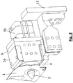
- Fig. 1-6 is a positioning device according to the invention for positioning a body component 1 with a receiving bore (see Figs. 3 - 5 ), which comprises a locating pin 2 with a conical end 3, which is designed to be guided axially through the locating bore of the body component 1 in order to center and position the body component 1.
- the locating pin 2 is supported in a radially floating manner in a retaining ring 4.
- the locating pin 2 has a cylindrical pin section which has a smaller outside diameter than the inside diameter of the retaining ring 4.
- the locating pin 2 is of at least two stages and, in addition to the cylindrical pin section, has a cylindrical collar 5, the cylindrical collar 5 having a larger diameter than the cylindrical pin section.
- the retaining ring 4 is also formed in two stages and the locating pin 2 is mounted in the retaining ring 4 in a radially floating manner in two stages.
- a first step of the retaining ring 4 has a larger inner diameter than the outer diameter of the cylindrical bolt section and a second step of the holding ring 4 has a larger inner diameter than the outer diameter of the cylindrical collar 5. So there is, as in Fig. 2 clearly visible, a game 18 between the first stage of the retaining ring 4 and the locating pin 2 and also between the second stage of the retaining ring 4 and the outer diameter of the cylindrical collar 5.
- the positioning device comprises a base body 6, the retaining ring 4 being fastened to the base body 6.
- the locating pin 2 is axially supported by the base body 6 and by the retaining ring 4, as in FIG Fig. 2 well visible.
- the receiving bolt 2 has at its end opposite the conical end 3 an axial recess in the form of an inner cone 7.
- the positioning device comprises a locking pin 8, the locking pin 8 having a conical end 9.
- the locking pin 8 is axially displaceable relative to the locating pin 2.
- the diameters of the inner cone 7 of the locating bolt 2 and of the conical end 9 of the locking bolt 8 match each other, so that the conical end 9 can be received in the inner cone 7 in contact.
- the locking pin 8 is guided through a bore in the base body 6 and axially displaceable relative to the base body 6.
- the locking pin 8 is mounted radially in the base body 6 by means of two bearing bushes 10.
- the bearing bushes 10 are arranged in the bore of the base body 6.
- the locking pin 8 can be moved axially relative to the locating pin 2 and relative to the base body 6.
- the pneumatic cylinder 11 is laterally attached to the base body 6 or a connection plate connected to the base body 6.
- the mounting bolt 2 with the corresponding diameter for the component 1 to be accommodated or its mounting bore is thus placed on the front of the base body 6 in a floating manner.
- the locating pin 2 has an attached collar 5 at the rear end and additionally an inner cone 7 at this end.
- the locating pin 2 is fastened in a radially floating manner with a retaining ring 4 screwed on at the front.
- the stepped bore of the front retaining ring 4 is larger in diameter to the locating pin 2 and to the attached collar 5 of the locating pin 2, as required.
- the width of the collar 5 from the mounting bolt 2 is minimally smaller than the inner width of the retaining ring 4.
- the mounting pin 2 can move freely radially in all directions.
- a locking pin 8 with a cone 9 attached at the front is installed in the base body 6, which is guided via bearing bushes 10.
- the cone angle corresponds to the inner cone 7 of the locating bolt 2.
- This locking pin 8 is pushed forwards or backwards by means of the pneumatic cylinder 11 placed on the back (in the direction of the in FIG Fig. 1 arrows).
- the picked-up component 1 is also brought into the correct position via the mounting pin 2. This is followed by further clamping steps for component 1.
- the positioning device can use the two inductive proximity switches, sensors 15 attached at the top of the base body 6, to sense the position of the metal indicator 14 and thus the locking pin 8 and the mounting pin 2 in order to provide a system control process with feedback about the position to be able to give the locating pin 2 (so-called INI query).
- the sensors 15 are protected by a cover 16 as a dirt cover cap and can be integrated into the control of the system in various systems.
- a dirt cover cap 13 with a sealing ring 12 is pressed on to the front of the mounting pin 2 to prevent the positioning device from becoming dirty.
- the dirt cover cap 13 therefore moves with the locating pin 2 and covers the "play" between the locating pin 2 and the retaining ring 4 - as protection against contamination. Therefore also in Fig. 6 no "game” visible.
- the dirt cap 13 thus moves with the locating pin 2 relative to the retaining ring 4 - for example, the dirt cap 13 slides on the (front) surface of the retaining ring 4 or a seal or a sliding ring is arranged in between.
- the stepped bore of the front retaining ring 4 is larger in diameter to the locating pin 2 and to the collar 5 of the locating pin 2, as required, in diameter.
- threaded bores and fitting bores for fastening in a device are made on the side and at the bottom (see Fig. 3 ).
- a positioning device can be used, for example, on so-called framer gates for side frames with mounting holes in body construction, or on robot-guided gripper frames for components with mounting holes in body construction and for a wide variety of thin-walled components with mounting holes that should not be damaged, and whose mounting holes are particularly provided with sealing plugs .
Landscapes
- Engineering & Computer Science (AREA)
- Mechanical Engineering (AREA)
- Insertion Pins And Rivets (AREA)
- Jigs For Machine Tools (AREA)
Abstract
Description
- Die vorliegende Erfindung betrifft eine Positioniervorrichtung, zum Positionieren eines Karosseriebauteils mit mindestens einer Aufnahmebohrung im Fahrzeugbau.
- Vielfach müssen im Automobilbau, insbesondere im Zuge des Karosseriebaus, dünnwandige Bauteile, meist Blechteile, exakt positioniert werden, insbesondere um an andere Karosseriebauteile oder Karosseriegruppen angeschweißt oder auf sonstige Weise gefügt zu werden. Die dünnwandigen Bauteile weisen dazu zumindest eine, üblicherweise aber zumindest zwei Aufnahmebohrungen auf. Aufnahmebolzen an einer Positioniervorrichtung werden dazu verwendet, durch diese Bohrungen der Karosserieteile hindurchzugreifen und die miteinander zu verbindenden Bauteile zu positionieren. Die Aufnahmebolzen weisen oft ein konisches Ende auf um einfacher in die Bohrungen zu gelangen und die Bauteile beim Durchtritt der Aufnahmebolzen zu zentrieren, daher werden solche Aufnahmebolzen auch "Zentrierbolzen" genannt. Nach einer solchen Positionierung der Bauteile folgen im Zuge der weiteren Montage oft Schritte des Fixierens oder Spannens der Bauteile und Schritte zum Fügen mit anderen Karosseriebauteilen.
- Die
DE 39 19 077 C1 offenbart beispielsweise eine Vorrichtung zum positionsdefinierten Aufspannen eines Werkstücks auf einem Bearbeitungstisch mit einer Werkstückaufnahme, auf welcher das Werkstück lösbar befestigt wird und welche mit Zentrieröffnungen versehen ist, die mit korrespondierend auf dem Bearbeitungstisch angeordneten, über diesen vorstehenden Zentrierzapfen zusammenwirken, wobei eine erste Gruppe von Zentrieröffnungen und Zentrierzapfen vorgesehen ist, die die Lage der Werkstückaufnahme in X- und Y-Richtung festlegen. - Die
EP 0 911 112 A1 offenbart eine druckmittelbetätigbare kombinierte Zentrier- und Spannvorrichtung, insbesondere zur Verwendung im Karosseriebau der Kfz-Industrie, mit einem bolzenförmigen Zentrierteil und einem Spannteil, wobei das Zentrierteil und das Spannteil abwechselnd in beiden Richtungen - spannend und zentrierend oder lösend - nacheinander durch Druckmitteldruck antreibbar und das Spannteil in und an dem bolzenförmigen Zentrierteil gelagert ist. - Die Aufnahmebohrungen in den Karosseriebauteilen werden teilweise später, jedenfalls nach der Positionierung der Bauteile, mit Dichtstopfen versehen um diese Öffnungen zu schließen.
- Problematisch ist, dass beim Durchtritt von Aufnahmebolzen durch die Bohrungen der dünnwandigen Bauteile, im Zuge der Positionierung, die Bohrungen bzw. die Karosseriebauteile im Bereich der Bohrungen manchmal beschädigt werden. An derartigen beschädigten Aufnahmebohrungen von Karosseriebauteilen kann es später, auch nach dem Anbringen von Dichtstopfen, zu einem unerwünschten Wassereintritt in die Karosserie kommen.
- Es ist eine Aufgabe der Erfindung, eine verbesserte Positioniervorrichtung, zum Positionieren eines Karosseriebauteils mit mindestens einer Aufnahmebohrung im Fahrzeugbau, anzugeben, die insbesondere Beschädigungen der Karosseriebauteile im Bereich der Aufnahmebohrungen während der Positionierung vermeidet.
- Die Lösung der Aufgabe erfolgt durch eine Positioniervorrichtung, zum Positionieren eines Karosseriebauteils mit mindestens einer Aufnahmebohrung im Fahrzeugbau, umfassend einen Aufnahmebolzen mit einem konischen Ende der dazu ausgebildet ist, axial durch die Aufnahmebohrung des Karosseriebauteils geführt zu werden um das Karosseriebauteil zu zentrieren und zu positionieren, wobei der Aufnahmebolzen radial schwimmend gelagert ist.
- Erfindungsgemäß ist ein Aufnahmebolzen mit konischem Ende zum Zentrieren und Positionieren eines Bauteils radial schwimmend gelagert. Es hat sich gezeigt, dass durch eine starre Ausbildung eines Aufnahmebolzens die Aufnahmebohrungen der positionierten Bauteile stärker beschädigt werden. Insbesondere bei mehrmaliger Aufnahme der Bauteile im Zuge der Fahrzeugmontage werden die Aufnahmebohrungen bei Verwendung starrer Aufnahmebolzen immer stärker aufgeweitet und/oder beschädigt. Die Folge sind höhere Maßungenauigkeiten oder Undichtheit der Karosseriebauteile. Durch die radial schwimmende Lagerung der Aufnahmebolzen können die Karosseriebauteile genau positioniert werden, erforderlichenfalls auch mehrmals positioniert, und werden dabei weniger oder gar nicht beschädigt.
- Das Wort "Bohrung" legt erfindungsgemäß nicht die Herstellungsweise der entsprechenden Öffnung fest und ist daher im Sinn einer durch das Bauteil führenden Öffnung mit einem üblicherweise runden Querschnitt zu verstehen.
- Bevorzugt weist der Aufnahmebolzen einen zylindrischen Bolzenabschnitt auf und ist in einem Haltering radial schwimmend gelagert. Der Haltering weist einen etwas größeren Innendurchmesser auf als der Außendurchmesser des zylindrischen Bolzenabschnitts. Es gibt also ein "Spiel" zwischen dem Haltering und dem Aufnahmebolzen bzw. dem zylindrischen Bolzenabschnitt des Aufnahmebolzens.
- Besonders bevorzugt ist der Aufnahmebolzen zweistufig ausgebildet und weist zusätzlich zum zylindrischen Bolzenabschnitt einen zylindrischen Bund auf, wobei der zylindrische Bund einen größeren Durchmesser aufweist als der zylindrische Bolzenabschnitt. Der Haltering ist ebenfalls zweistufig ausgebildet und der Aufnahmebolzen zweistufig radial schwimmend in diesem Haltering radial gelagert. Eine erste Stufe des Halterings weist dazu einen größeren Innendurchmesser auf als der Außendurchmesser des zylindrischen Bolzenabschnitts und eine zweite Stufe des Halterings weist einen größeren Innendurchmesser auf als der Außendurchmesser des zylindrischen Bundes. Es gibt also ein "Spiel" zwischen erster Stufe des Halteringes und Aufnahmebolzen sowie auch zwischen zweiter Stufe des Halteringes und Außendurchmesser des zylindrischen Bundes.
- Vorzugsweise umfasst die Positioniervorrichtung einen Grundkörper, wobei der Haltering am Grundkörper befestigt ist oder einstückig mit dem Grundkörper ausgebildet ist, wobei der Aufnahmebolzen axial durch den Grundkörper und/oder durch den Haltering festgelegt ist. Der Aufnahmebolzen kann im Wesentlichen, zumindest axial, bevorzugt aber auch radial abgesehen von den Freiheitsgraden aufgrund der schwimmenden Lagerung, zusammen mit dem Grundkörper bewegt und positioniert werden.
- Bevorzugt weist der Aufnahmebolzen an seinem dem konischen Ende gegenüberliegenden Ende eine Ausnehmung in Form eines Innenkegels auf. Der Innenkegel verläuft axial an diesem Ende des Aufnahmebolzens in das Innere des Aufnahmebolzens und bevorzugt koaxial mit dem Aufnahmebolzen, um eine mit dem Aufnahmebolzen gemeinsame Mittelachse.
- Die Positioniervorrichtung umfasst bevorzugt einen Sperrbolzen, wobei der Sperrbolzen ein konisches Ende aufweist, wobei der Sperrbolzen axial gegenüber dem Aufnahmebolzen verschieblich ist. Der Sperrbolzen kann daher zum Aufnahmebolzen hin verschoben werden, insbesondere so dass der Sperrbolzen in Kontakt mit dem Aufnahmebolzen tritt.
- Die Durchmesser des Innenkegels des Aufnahmebolzens und des konischen Endes des Sperrbolzens passen bevorzugt zueinander, so dass das konische Ende durch Passung in den Innenkegel aufgenommen werden kann. Diese Geometrie der beiden Kegel bestimmt im Wesentlichen auch das mögliche "Spiel" bzw. die schwimmende Lagerung zwischen dem Aufnahmebolzen und dem angesetzten Bund einerseits und dem Innendurchmesser des Halteringes andererseits und kann daher zur Bereitstellung eines gewünschten Spiels verwendet werden. Ist beispielsweise der Durchmesser des Innenkegels des Aufnahmebolzens kleiner, so ist auch das "Spiel" kleiner bzw. die radial schwimmende Bewegung des Aufnahmebolzens kleiner.
- Der Sperrbolzen kann durch eine Bohrung des Grundkörpers geführt sein und der Sperrbolzen kann axial gegenüber dem Grundkörper verschieblich sein, somit in der Bohrung des Grundkörpers verschoben werden.
- Bevorzugt ist der Sperrbolzen mittels zweier Lagerbuchsen im Grundkörper radial gelagert, insbesondere in der Bohrung des Grundkörpers.
- Vorzugsweise kann der Sperrbolzen mittels eines Pneumatikzylinders axial gegenüber dem Aufnahmebolzen und gegenüber dem Grundkörper verschoben werden. Der Pneumatikzylinder kann am Grundkörper befestigt sein.
- Die Erfindung wird im Folgenden beispielhaft unter Bezugnahme auf die Zeichnungen beschrieben.
- Fig. 1
- ist eine Explosionsdarstellung, welche eine erfindungsgemäße Positioniervorrichtung zeigt.
- Fig. 2
- ist eine seitliche Schnittansicht einer erfindungsgemäßen Positioniervorrichtung gemäß
Fig. 1 . - Fig. 3
- ist eine dreidimensionale Darstellung einer erfindungsgemäßen Positioniervorrichtung gemäß
Fig. 2 mit zu positionierendem Karosseriebauteil. - Fig. 4
- ist eine dreidimensionale und teilweise geschnittene Darstellung einer erfindungsgemäßen Positioniervorrichtung gemäß
Fig. 3 in einem ersten Zustand. - Fig. 5
- ist eine dreidimensionale und teilweise geschnittene Darstellung einer erfindungsgemäßen Positioniervorrichtung gemäß
Fig. 3 in einem zweiten Zustand. - Fig. 6
- ist eine dreidimensionale Darstellung einer erfindungsgemäßen Positioniervorrichtung gemäß
Fig. 2 aus einer weiteren Perspektive. - In den
Fig. 1-6 ist eine erfindungsgemäße Positioniervorrichtung zum Positionieren eines Karosseriebauteils 1 mit einer Aufnahmebohrung (sieheFigs. 3 - 5 ) dargestellt, welche einen Aufnahmebolzen 2 mit einem konischen Ende 3 umfasst, der dazu ausgebildet ist, axial durch die Aufnahmebohrung des Karosseriebauteils 1 geführt zu werden um das Karosseriebauteil 1 zu zentrieren und zu positionieren. - Der Aufnahmebolzen 2 ist radial schwimmend gelagert in einem Haltering 4.
- Der Aufnahmebolzen 2 weist einen zylindrischen Bolzenabschnitt auf, der einen geringeren Außendurchmesser aufweist, als der Innendurchmesser des Halterings 4.
- Genauer ist der Aufnahmebolzen 2 zumindest zweistufig ausgebildet und weist zusätzlich zum zylindrischen Bolzenabschnitt einen zylindrischen Bund 5 auf, wobei der zylindrische Bund 5 einen größeren Durchmesser aufweist, als der zylindrische Bolzenabschnitt.
- Der Haltering 4 ist ebenfalls zweistufig ausgebildet und der Aufnahmebolzen 2 ist zweistufig radial schwimmend im Haltering 4 gelagert. Eine erste Stufe des Halterings 4 weist einen größeren Innendurchmesser auf, als der Außendurchmesser des zylindrischen Bolzenabschnitts und eine zweite Stufe des Halterings 4 weist einen größeren Innendurchmesser auf als der Außendurchmesser des zylindrischen Bundes 5. Es gibt also, wie in
Fig. 2 gut ersichtlich, ein Spiel 18 zwischen erster Stufe des Halteringes 4 und Aufnahmebolzen 2 sowie auch zwischen zweiter Stufe des Halteringes 4 und Außendurchmesser des zylindrischen Bundes 5. - Die Positioniervorrichtung umfasst einen Grundkörper 6, wobei der Haltering 4 am Grundkörper 6 befestigt ist. Der Aufnahmebolzen 2 ist axial durch den Grundkörper 6 und durch den Haltering 4 gelagert, wie in
Fig. 2 gut ersichtlich. - Der Aufnahmebolzen 2 weist an seinem dem konischen Ende 3 gegenüberliegenden Ende eine axiale Ausnehmung in Form eines Innenkegels 7 auf.
- Die Positioniervorrichtung umfasst einen Sperrbolzen 8, wobei der Sperrbolzen 8 ein konisches Ende 9 aufweist. Der Sperrbolzen 8 ist axial gegenüber dem Aufnahmebolzen 2 verschieblich.
- Die Durchmesser des Innenkegels 7 des Aufnahmebolzens 2 und des konischen Endes 9 des Sperrbolzens 8 passen zueinander, so dass das konische Ende 9 anliegend in den Innenkegel 7 aufgenommen werden kann.
- Der Sperrbolzen 8 ist durch eine Bohrung des Grundkörpers 6 geführt und axial gegenüber dem Grundkörper 6 verschieblich.
- Der Sperrbolzen 8 ist mittels zweier Lagerbuchsen 10 im Grundkörper 6 radial gelagert. Die Lagerbuchsen 10 sind in der Bohrung des Grundkörpers 6 angeordnet.
- Mittels eines Pneumatikzylinders 11 kann der Sperrbolzen 8 axial gegenüber dem Aufnahmebolzen 2 und gegenüber dem Grundkörper 6 verschoben werden. Der Pneumatikzylinder 11 ist seitlich am Grundkörper 6 oder einer mit dem Grundkörper 6 verbundenen Anschlussplatte befestigt.
- Zusammengefasst ist somit an dem Grundkörper 6 stirnseitig der Aufnahmebolzen 2, mit dem für das aufzunehmende Bauteil 1 bzw. dessen Aufnahmebohrung entsprechendem Durchmesser, schwimmend aufgesetzt. Der Aufnahmebolzen 2 hat am hinteren Ende einen angesetzten Bund 5 und zusätzlich an diesem Ende einen Innenkegel 7. Der Aufnahmebolzen 2 wird mit einem vorne angeschraubten Haltering 4 radial schwimmend befestigt. Die abgestufte Bohrung des vorderen Halteringes 4 ist im Durchmesser zum Aufnahmebolzen 2 sowie zum angesetzten Bund 5 des Aufnahmebolzens 2 je nach Bedarf im Durchmesser größer. Die Breite des angesetzten Bundes 5 vom Aufnahmebolzen 2 ist zur inneren Breite des Halteringes 4 minimal geringer. Somit kann sich der Aufnahmebolzen 2 radial in alle Richtungen frei bewegen.
- Weiters ist im Grundkörper 6 ein über Lagerbuchsen 10 geführter Sperrstift 8 mit vorne angesetztem Kegel 9 eingebaut. Der Kegelwinkel entspricht dem Innenkegel 7 des Aufnahmebolzens 2. Dieser Sperrstift 8 wird mittels hinten aufgesetztem Pneumatikzylinder 11 nach vorne bzw. nach hinten geschoben (in Richtung der in
Fig. 1 eingezeichneten Pfeile). - Ist der eingebaute Sperrstift 8 mit dem vorne angesetztem Kegel 9 nach hinten gezogen, wie in
Fig. 5 dargestellt, kann sich der vordere Aufnahmebolzen 2 radial frei bewegen. - Wird der eingebaute Sperrstift 8 mit der Kraft des hinten angebauten Pneumatikzylinders 11 nach vorne gedrückt, wie in
Fig. 4 dargestellt, wird der Aufnahmebolzen 2 durch die beiden Kegel 9 und 7 in die zentrische Position gebracht und verriegelt. - Über den Aufnahmebolzen 2 wird ebenso das aufgenommene Bauteil 1 in die richtige Position gebracht. Danach folgen weitere Spannschritte für das Bauteil 1.
- Mittels eines eingeschraubten Metallstiftes als Metallindikator 14 im Sperrbolzen 8 kann die Positioniervorrichtung über die beiden oben am Grundkörper 6 angebrachten induktiven Näherungsschalter, Sensoren 15, die Position des Metallindikators 14 und somit des Sperrbolzens 8 und des Aufnahmebolzens 2 sensieren um einem Anlagensteuerungsprozess eine Rückmeldung über die Position des Aufnahmebolzens 2 geben zu können (sogenannte INI-Abfrage). Die Sensoren 15 sind mittels einer Abdeckung 16 als Schmutzabdeckkappe geschützt und können in verschiedenen Anlagen in die Steuerung der Anlage eingebunden werden.
- Gegen Verschmutzung der Positioniervorrichtung ist vorne am Aufnahmebolzen 2 eine Schmutzabdeckkappe 13 mit Dichtring 12 aufgepresst.
Die Schmutzabdeckkappe 13 bewegt sich daher mit dem Aufnahmebolzen 2 und deckt das zwischen Aufnahmebolzen 2 und Haltering 4 vorhandene "Spiel" ab - als Schutz vor Verschmutzung. Daher ist auch inFig. 6 kein "Spiel" ersichtlich. Die Schmutzabdeckkappe 13 bewegt sich also mit dem Aufnahmebolzen 2 relativ zum Haltering 4 - beispielsweise gleitet die Schmutzabdeckkappe 13 an der (vorderen) Oberfläche des Halteringes 4 oder es ist dazwischen eine Dichtung oder ein Gleitring angeordnet.
Wie oben erwähnt, ist die abgestufte Bohrung des vorderen Halteringes 4 im Durchmesser zum Aufnahmebolzen 2 sowie zum angesetzten Bund 5 des Aufnahmebolzens 2 je nach Bedarf im Durchmesser größer. Bei einer Ausführung mit Schmutzabdeckkappe 13 wie inFig. 2 dargestellt, kann dies folgendermaßen ausgebildet sein: Da die Schmutzabdeckkappe 13 hier auf den Aufnahmebolzen 2 aufgepresst ist und aus Stabilitätsgründen in den Innendurchmesser des vorderen Halteringes 4 ragt, muss die Bohrung hier um die Wandstärke des den Aufnahmebolzen 2 umschließenden "Schaftes" der Schmutzabdeckkappe 13 größer gebohrt werden, damit das "Spiel" auch im Bereich des vorderen Halteringes 4 für das Bauteil 2, 5 gegeben ist. Dass der Schaft der Schmutzabdeckkappe 13 in den Innendurchmesser des Halteringes 4 ragt, ist nur ein Ausführungsbeispiel. Eine Schmutzabdeckkappe könnte auch nur im Bereich vor dem Haltering 4 auf den Aufnahmebolzen 2 aufgebracht bzw. befestigt, insbesondere aufgepresst sein. - Seitlich, sowie unten, sind am Grundkörper 6 Gewindebohrungen und Passbohrungen zur Befestigung in einer Vorrichtung, beispielsweise an einem Greifer 17 bzw. Greiferrahmen, eingebracht (siehe
Fig. 3 ). - Eine erfindungsgemäße Positioniervorrichtung kann beispielsweise an sogenannten Framer-Gates für Seitenrahmen mit Aufnahmelöchern im Karosseriebau eingesetzt werden, oder an robotergeführten Greiferrahmen für Bauteile mit Aufnahmelöchern im Karosseriebau und für verschiedenste dünnwandige Bauteile mit Aufnahmelöchern die nicht beschädigt werden sollen, und deren Aufnahmelöcher insbesondere mit Dichtstopfen versehen werden.
-
- 1
- Karosseriebauteil
- 2
- Aufnahmebolzen
- 3
- konisches Ende
- 4
- Haltering
- 5
- zylindrischer Bund
- 6
- Grundkörper
- 7
- Innenkegel
- 8
- Sperrbolzen
- 9
- konisches Ende
- 10
- Lagerbuchse
- 11
- Pneumatikzylinder
- 12
- Dichtring
- 13
- Abdeckkappe
- 14
- Metallindikator
- 15
- Sensor
- 16
- Abdeckung
- 17
- Greifer
- 18
- Spiel
Claims (10)
- Positioniervorrichtung, zum Positionieren eines Karosseriebauteils (1) mit mindestens einer Aufnahmebohrung im Fahrzeugbau, umfassend einen Aufnahmebolzen (2) mit einem konischen Ende (3), der dazu ausgebildet ist, axial durch die Aufnahmebohrung des Karosseriebauteils (1) geführt zu werden um das Karosseriebauteil (1) zu zentrieren und zu positionieren,
dadurch gekennzeichnet, dass der Aufnahmebolzen (2) radial schwimmend gelagert ist. - Positioniervorrichtung nach Anspruch 1,
dadurch gekennzeichnet, dass der Aufnahmebolzen (2) einen zylindrischen Bolzenabschnitt aufweist und in einem Haltering (4) radial schwimmend gelagert ist, wobei der Haltering (4) einen größeren Innendurchmesser aufweist als der Außendurchmesser des zylindrischen Bolzenabschnitts. - Positioniervorrichtung nach Anspruch 2,
dadurch gekennzeichnet, dass der Aufnahmebolzen (2) zweistufig ausgebildet ist und zusätzlich zum zylindrischen Bolzenabschnitt einen zylindrischen Bund (5) aufweist, wobei der zylindrische Bund (5) einen größeren Durchmesser aufweist als der zylindrische Bolzenabschnitt, wobei der Haltering (4) zweistufig ausgebildet ist und der Aufnahmebolzen (2) zweistufig radial schwimmend im Haltering (4) radial gelagert ist, wobei eine erste Stufe des Halterings (4) einen größeren Innendurchmesser aufweist als der Außendurchmesser des zylindrischen Bolzenabschnitts und eine zweite Stufe des Halterings (4) einen größeren Innendurchmesser aufweist als der Außendurchmesser des zylindrischen Bundes (5). - Positioniervorrichtung nach zumindest einem der Ansprüche 2 oder 3,
dadurch gekennzeichnet, dass die Positioniervorrichtung einen Grundkörper (6) umfasst, wobei der Haltering (4) am Grundkörper (6) befestigt ist oder einstückig mit dem Grundkörper (6) ausgebildet ist, wobei der Aufnahmebolzen (2) axial durch den Grundkörper (6) und/oder durch den Haltering (4) festgelegt ist. - Positioniervorrichtung nach zumindest einem der vorhergehenden Ansprüche,
dadurch gekennzeichnet, dass der Aufnahmebolzen (2) an seinem dem konischen Ende (3) gegenüberliegenden Ende eine axiale Ausnehmung in Form eines Innenkegels (7) aufweist. - Positioniervorrichtung nach zumindest einem der vorhergehenden Ansprüche,
dadurch gekennzeichnet, dass die Positioniervorrichtung einen Sperrbolzen (8) umfasst, wobei der Sperrbolzen (8) ein konisches Ende (9) aufweist, wobei der Sperrbolzen (8) axial gegenüber dem Aufnahmebolzen (2) verschieblich ist. - Positioniervorrichtung nach Anspruch 5 und 6,
dadurch gekennzeichnet, dass die Durchmesser des Innenkegels (7) des Aufnahmebolzens (2) und des konischen Endes (9) des Sperrbolzens (8) zueinander passen, so dass das konische Ende (9) durch Passung in den Innenkegel (7) aufgenommen werden kann. - Positioniervorrichtung nach Anspruch 4 und 6,
dadurch gekennzeichnet, dass der Sperrbolzen (8) durch eine Bohrung des Grundkörpers (6) geführt ist und der Sperrbolzen (8) axial gegenüber dem Grundkörper (6) verschieblich ist. - Positioniervorrichtung nach Anspruch 8,
dadurch gekennzeichnet, dass der Sperrbolzen (8) mittels zweier Lagerbuchsen (10) im Grundkörper (6) radial gelagert ist. - Positioniervorrichtung nach zumindest einem der Ansprüche 6 bis 9,
dadurch gekennzeichnet, dass der Sperrbolzen (8) mittels eines Pneumatikzylinders (11) axial gegenüber dem Aufnahmebolzen (2) verschoben werden kann.
Priority Applications (2)
| Application Number | Priority Date | Filing Date | Title |
|---|---|---|---|
| EP18197206.8A EP3628440B1 (de) | 2018-09-27 | 2018-09-27 | Positioniervorrichtung |
| US16/560,038 US11198201B2 (en) | 2018-09-27 | 2019-09-04 | Positioning device |
Applications Claiming Priority (1)
| Application Number | Priority Date | Filing Date | Title |
|---|---|---|---|
| EP18197206.8A EP3628440B1 (de) | 2018-09-27 | 2018-09-27 | Positioniervorrichtung |
Publications (2)
| Publication Number | Publication Date |
|---|---|
| EP3628440A1 true EP3628440A1 (de) | 2020-04-01 |
| EP3628440B1 EP3628440B1 (de) | 2022-03-16 |
Family
ID=63708103
Family Applications (1)
| Application Number | Title | Priority Date | Filing Date |
|---|---|---|---|
| EP18197206.8A Active EP3628440B1 (de) | 2018-09-27 | 2018-09-27 | Positioniervorrichtung |
Country Status (2)
| Country | Link |
|---|---|
| US (1) | US11198201B2 (de) |
| EP (1) | EP3628440B1 (de) |
Families Citing this family (4)
| Publication number | Priority date | Publication date | Assignee | Title |
|---|---|---|---|---|
| US12023773B1 (en) * | 2020-08-13 | 2024-07-02 | E&E Custom Products, Llc | Floating shot pin assembly and method |
| CN113001435B (zh) * | 2021-02-22 | 2022-09-23 | 航天科工空间工程发展有限公司 | 一种定位系统、承载装置及定位装置 |
| EP4206011B1 (de) * | 2022-01-04 | 2025-09-17 | Ningbo Geely Automobile Research & Development Co., Ltd. | Türeinstellwerkzeug |
| CN115008230A (zh) * | 2022-06-24 | 2022-09-06 | 上汽通用五菱汽车股份有限公司 | 一种浮动定位夹紧机构 |
Citations (5)
| Publication number | Priority date | Publication date | Assignee | Title |
|---|---|---|---|---|
| DE3919077C1 (de) | 1989-06-10 | 1990-07-26 | Erowa Ag, Reinach, Ch | |
| EP0911112A1 (de) | 1997-10-21 | 1999-04-28 | TÜNKERS MASCHINENBAU GmbH | Druckmittelbetätigbare kombinierte Zentrier- und Spannvorrichtung, insbesondere zur Verwendung im Karrosseriebau der Kfz-Industrie |
| WO2004004977A2 (en) * | 2002-07-10 | 2004-01-15 | Welker Bearing Company | Locating assembly having an extendable clamping finger |
| DE202016101411U1 (de) * | 2016-03-14 | 2017-06-19 | Schunk Gmbh & Co. Kg Spann- Und Greiftechnik | Einzugsspannelement, insbesondere Einzugsspannbolzen oder Einzugsspannring, und zugehöriges Spannsystem |
| DE102016122090A1 (de) * | 2016-11-17 | 2018-05-17 | Frank Nickl | Spannsystem |
Family Cites Families (1)
| Publication number | Priority date | Publication date | Assignee | Title |
|---|---|---|---|---|
| US7156385B2 (en) * | 2003-06-03 | 2007-01-02 | Norgren Automotive, Inc. | Linearly adjustable apparatus for locating a workpiece |
-
2018
- 2018-09-27 EP EP18197206.8A patent/EP3628440B1/de active Active
-
2019
- 2019-09-04 US US16/560,038 patent/US11198201B2/en active Active
Patent Citations (5)
| Publication number | Priority date | Publication date | Assignee | Title |
|---|---|---|---|---|
| DE3919077C1 (de) | 1989-06-10 | 1990-07-26 | Erowa Ag, Reinach, Ch | |
| EP0911112A1 (de) | 1997-10-21 | 1999-04-28 | TÜNKERS MASCHINENBAU GmbH | Druckmittelbetätigbare kombinierte Zentrier- und Spannvorrichtung, insbesondere zur Verwendung im Karrosseriebau der Kfz-Industrie |
| WO2004004977A2 (en) * | 2002-07-10 | 2004-01-15 | Welker Bearing Company | Locating assembly having an extendable clamping finger |
| DE202016101411U1 (de) * | 2016-03-14 | 2017-06-19 | Schunk Gmbh & Co. Kg Spann- Und Greiftechnik | Einzugsspannelement, insbesondere Einzugsspannbolzen oder Einzugsspannring, und zugehöriges Spannsystem |
| DE102016122090A1 (de) * | 2016-11-17 | 2018-05-17 | Frank Nickl | Spannsystem |
Also Published As
| Publication number | Publication date |
|---|---|
| EP3628440B1 (de) | 2022-03-16 |
| US11198201B2 (en) | 2021-12-14 |
| US20200101572A1 (en) | 2020-04-02 |
Similar Documents
| Publication | Publication Date | Title |
|---|---|---|
| EP2720907B1 (de) | Befestigungselement mit toleranzausgleichsfunktion | |
| EP1869334B1 (de) | Gleitlager, gleitlagersystem und montage eines gleitlagersystems | |
| EP3628440B1 (de) | Positioniervorrichtung | |
| DE102019111422A1 (de) | Nabenabdeckung für eine Reifenbefüllvorrichtung eines Fahrzeugs | |
| DE102013208635B4 (de) | Ausgleichsvorrichtung | |
| DE102016206864A1 (de) | Kugelgelenk, insbesondere für ein Fahrwerk eines Kraftfahrzeugs, sowie Verfahren zur Montage eines solchen Kugelgelenks | |
| EP0854076B1 (de) | Verfahren und Vorrichtung zum Einpressen einer vormontierten Kugelgelenk-Patrone in ein Lagerauge eines Lenkerhebels | |
| DE102005009721B3 (de) | Lageranordnung | |
| DE69215493T2 (de) | Haltevorrichtung mit entfernbarer Zentrierbüchse | |
| EP3110587B1 (de) | Lötspitzenbefestigungssystem | |
| DE102015207176A1 (de) | Verfahren zur Herstellung eines Fahrwerkbauteils | |
| DE102015211419A1 (de) | Anordnung zur Abdichtung eines Aktuators und Adapterring zur Abdichtung | |
| EP1187995B1 (de) | Fügeverbindung und ein verfahren zur herstellung derselben, sowie lenksäule von kraftfahrzeugen mit einer solchen fügeverbindung | |
| EP1503114B1 (de) | Kolben-Kolbenstangen-Einheit | |
| DE102016123364A1 (de) | Klemmvorrichtung und Verfahren zur Herstellung von Klemmvorrichtungen | |
| EP3344431B1 (de) | Druckmittelaggregat, mit einem durch spritzgiessen hergestellten gehäuse aus kunststoff sowie verfahren zu seiner herstellung | |
| EP3966057B1 (de) | Aggregatelagerung in einem fahrzeug | |
| EP0600227B1 (de) | Raumgelenkiges Kraftwagentürscharnier | |
| DE19734785C2 (de) | Selbstkalibrierendes Verbindungselement für Verstelleinrichtungen in Kraftfahrzeugen | |
| DE3425158C2 (de) | ||
| DE69907173T2 (de) | Vorrichtung zur vesprödung einer kraftfahrzeugpedal-drehachse | |
| DE102005035857B4 (de) | Druckzylinder | |
| AT402656B (de) | Hydraulischer arbeitszylinder hydraulischer arbeitszylinder | |
| EP1391619B1 (de) | Kugelgelenk | |
| DE102017116255A1 (de) | Gewindemutter für einen Kugelgewindetrieb |
Legal Events
| Date | Code | Title | Description |
|---|---|---|---|
| PUAI | Public reference made under article 153(3) epc to a published international application that has entered the european phase |
Free format text: ORIGINAL CODE: 0009012 |
|
| STAA | Information on the status of an ep patent application or granted ep patent |
Free format text: STATUS: THE APPLICATION HAS BEEN PUBLISHED |
|
| AK | Designated contracting states |
Kind code of ref document: A1 Designated state(s): AL AT BE BG CH CY CZ DE DK EE ES FI FR GB GR HR HU IE IS IT LI LT LU LV MC MK MT NL NO PL PT RO RS SE SI SK SM TR |
|
| AX | Request for extension of the european patent |
Extension state: BA ME |
|
| STAA | Information on the status of an ep patent application or granted ep patent |
Free format text: STATUS: REQUEST FOR EXAMINATION WAS MADE |
|
| 17P | Request for examination filed |
Effective date: 20200803 |
|
| RBV | Designated contracting states (corrected) |
Designated state(s): AL AT BE BG CH CY CZ DE DK EE ES FI FR GB GR HR HU IE IS IT LI LT LU LV MC MK MT NL NO PL PT RO RS SE SI SK SM TR |
|
| STAA | Information on the status of an ep patent application or granted ep patent |
Free format text: STATUS: EXAMINATION IS IN PROGRESS |
|
| 17Q | First examination report despatched |
Effective date: 20210621 |
|
| GRAP | Despatch of communication of intention to grant a patent |
Free format text: ORIGINAL CODE: EPIDOSNIGR1 |
|
| STAA | Information on the status of an ep patent application or granted ep patent |
Free format text: STATUS: GRANT OF PATENT IS INTENDED |
|
| RIC1 | Information provided on ipc code assigned before grant |
Ipc: B62D 65/02 20060101ALI20210915BHEP Ipc: B23Q 3/18 20060101AFI20210915BHEP |
|
| INTG | Intention to grant announced |
Effective date: 20211011 |
|
| GRAS | Grant fee paid |
Free format text: ORIGINAL CODE: EPIDOSNIGR3 |
|
| GRAA | (expected) grant |
Free format text: ORIGINAL CODE: 0009210 |
|
| STAA | Information on the status of an ep patent application or granted ep patent |
Free format text: STATUS: THE PATENT HAS BEEN GRANTED |
|
| AK | Designated contracting states |
Kind code of ref document: B1 Designated state(s): AL AT BE BG CH CY CZ DE DK EE ES FI FR GB GR HR HU IE IS IT LI LT LU LV MC MK MT NL NO PL PT RO RS SE SI SK SM TR |
|
| REG | Reference to a national code |
Ref country code: GB Ref legal event code: FG4D Free format text: NOT ENGLISH |
|
| REG | Reference to a national code |
Ref country code: CH Ref legal event code: EP Ref country code: DE Ref legal event code: R096 Ref document number: 502018009095 Country of ref document: DE |
|
| REG | Reference to a national code |
Ref country code: IE Ref legal event code: FG4D Free format text: LANGUAGE OF EP DOCUMENT: GERMAN |
|
| REG | Reference to a national code |
Ref country code: AT Ref legal event code: REF Ref document number: 1475543 Country of ref document: AT Kind code of ref document: T Effective date: 20220415 |
|
| REG | Reference to a national code |
Ref country code: LT Ref legal event code: MG9D |
|
| REG | Reference to a national code |
Ref country code: NL Ref legal event code: MP Effective date: 20220316 |
|
| PG25 | Lapsed in a contracting state [announced via postgrant information from national office to epo] |
Ref country code: SE Free format text: LAPSE BECAUSE OF FAILURE TO SUBMIT A TRANSLATION OF THE DESCRIPTION OR TO PAY THE FEE WITHIN THE PRESCRIBED TIME-LIMIT Effective date: 20220316 Ref country code: RS Free format text: LAPSE BECAUSE OF FAILURE TO SUBMIT A TRANSLATION OF THE DESCRIPTION OR TO PAY THE FEE WITHIN THE PRESCRIBED TIME-LIMIT Effective date: 20220316 Ref country code: NO Free format text: LAPSE BECAUSE OF FAILURE TO SUBMIT A TRANSLATION OF THE DESCRIPTION OR TO PAY THE FEE WITHIN THE PRESCRIBED TIME-LIMIT Effective date: 20220616 Ref country code: LT Free format text: LAPSE BECAUSE OF FAILURE TO SUBMIT A TRANSLATION OF THE DESCRIPTION OR TO PAY THE FEE WITHIN THE PRESCRIBED TIME-LIMIT Effective date: 20220316 Ref country code: HR Free format text: LAPSE BECAUSE OF FAILURE TO SUBMIT A TRANSLATION OF THE DESCRIPTION OR TO PAY THE FEE WITHIN THE PRESCRIBED TIME-LIMIT Effective date: 20220316 Ref country code: BG Free format text: LAPSE BECAUSE OF FAILURE TO SUBMIT A TRANSLATION OF THE DESCRIPTION OR TO PAY THE FEE WITHIN THE PRESCRIBED TIME-LIMIT Effective date: 20220616 |
|
| PG25 | Lapsed in a contracting state [announced via postgrant information from national office to epo] |
Ref country code: LV Free format text: LAPSE BECAUSE OF FAILURE TO SUBMIT A TRANSLATION OF THE DESCRIPTION OR TO PAY THE FEE WITHIN THE PRESCRIBED TIME-LIMIT Effective date: 20220316 Ref country code: GR Free format text: LAPSE BECAUSE OF FAILURE TO SUBMIT A TRANSLATION OF THE DESCRIPTION OR TO PAY THE FEE WITHIN THE PRESCRIBED TIME-LIMIT Effective date: 20220617 Ref country code: FI Free format text: LAPSE BECAUSE OF FAILURE TO SUBMIT A TRANSLATION OF THE DESCRIPTION OR TO PAY THE FEE WITHIN THE PRESCRIBED TIME-LIMIT Effective date: 20220316 |
|
| PG25 | Lapsed in a contracting state [announced via postgrant information from national office to epo] |
Ref country code: NL Free format text: LAPSE BECAUSE OF FAILURE TO SUBMIT A TRANSLATION OF THE DESCRIPTION OR TO PAY THE FEE WITHIN THE PRESCRIBED TIME-LIMIT Effective date: 20220316 |
|
| REG | Reference to a national code |
Ref country code: DE Ref legal event code: R081 Ref document number: 502018009095 Country of ref document: DE Owner name: MAGNA STEYR FAHRZEUGTECHNIK GMBH & CO KG, AT Free format text: FORMER OWNER: MAGNA STEYR FAHRZEUGTECHNIK AG & CO KG, GRAZ, AT |
|
| PG25 | Lapsed in a contracting state [announced via postgrant information from national office to epo] |
Ref country code: SM Free format text: LAPSE BECAUSE OF FAILURE TO SUBMIT A TRANSLATION OF THE DESCRIPTION OR TO PAY THE FEE WITHIN THE PRESCRIBED TIME-LIMIT Effective date: 20220316 Ref country code: SK Free format text: LAPSE BECAUSE OF FAILURE TO SUBMIT A TRANSLATION OF THE DESCRIPTION OR TO PAY THE FEE WITHIN THE PRESCRIBED TIME-LIMIT Effective date: 20220316 Ref country code: RO Free format text: LAPSE BECAUSE OF FAILURE TO SUBMIT A TRANSLATION OF THE DESCRIPTION OR TO PAY THE FEE WITHIN THE PRESCRIBED TIME-LIMIT Effective date: 20220316 Ref country code: PT Free format text: LAPSE BECAUSE OF FAILURE TO SUBMIT A TRANSLATION OF THE DESCRIPTION OR TO PAY THE FEE WITHIN THE PRESCRIBED TIME-LIMIT Effective date: 20220718 Ref country code: ES Free format text: LAPSE BECAUSE OF FAILURE TO SUBMIT A TRANSLATION OF THE DESCRIPTION OR TO PAY THE FEE WITHIN THE PRESCRIBED TIME-LIMIT Effective date: 20220316 Ref country code: EE Free format text: LAPSE BECAUSE OF FAILURE TO SUBMIT A TRANSLATION OF THE DESCRIPTION OR TO PAY THE FEE WITHIN THE PRESCRIBED TIME-LIMIT Effective date: 20220316 Ref country code: CZ Free format text: LAPSE BECAUSE OF FAILURE TO SUBMIT A TRANSLATION OF THE DESCRIPTION OR TO PAY THE FEE WITHIN THE PRESCRIBED TIME-LIMIT Effective date: 20220316 |
|
| PG25 | Lapsed in a contracting state [announced via postgrant information from national office to epo] |
Ref country code: PL Free format text: LAPSE BECAUSE OF FAILURE TO SUBMIT A TRANSLATION OF THE DESCRIPTION OR TO PAY THE FEE WITHIN THE PRESCRIBED TIME-LIMIT Effective date: 20220316 Ref country code: IS Free format text: LAPSE BECAUSE OF FAILURE TO SUBMIT A TRANSLATION OF THE DESCRIPTION OR TO PAY THE FEE WITHIN THE PRESCRIBED TIME-LIMIT Effective date: 20220716 Ref country code: AL Free format text: LAPSE BECAUSE OF FAILURE TO SUBMIT A TRANSLATION OF THE DESCRIPTION OR TO PAY THE FEE WITHIN THE PRESCRIBED TIME-LIMIT Effective date: 20220316 |
|
| REG | Reference to a national code |
Ref country code: DE Ref legal event code: R097 Ref document number: 502018009095 Country of ref document: DE |
|
| PLBE | No opposition filed within time limit |
Free format text: ORIGINAL CODE: 0009261 |
|
| STAA | Information on the status of an ep patent application or granted ep patent |
Free format text: STATUS: NO OPPOSITION FILED WITHIN TIME LIMIT |
|
| PG25 | Lapsed in a contracting state [announced via postgrant information from national office to epo] |
Ref country code: DK Free format text: LAPSE BECAUSE OF FAILURE TO SUBMIT A TRANSLATION OF THE DESCRIPTION OR TO PAY THE FEE WITHIN THE PRESCRIBED TIME-LIMIT Effective date: 20220316 |
|
| 26N | No opposition filed |
Effective date: 20221219 |
|
| PG25 | Lapsed in a contracting state [announced via postgrant information from national office to epo] |
Ref country code: SI Free format text: LAPSE BECAUSE OF FAILURE TO SUBMIT A TRANSLATION OF THE DESCRIPTION OR TO PAY THE FEE WITHIN THE PRESCRIBED TIME-LIMIT Effective date: 20220316 |
|
| PG25 | Lapsed in a contracting state [announced via postgrant information from national office to epo] |
Ref country code: MC Free format text: LAPSE BECAUSE OF FAILURE TO SUBMIT A TRANSLATION OF THE DESCRIPTION OR TO PAY THE FEE WITHIN THE PRESCRIBED TIME-LIMIT Effective date: 20220316 |
|
| REG | Reference to a national code |
Ref country code: CH Ref legal event code: PL |
|
| REG | Reference to a national code |
Ref country code: BE Ref legal event code: MM Effective date: 20220930 |
|
| PG25 | Lapsed in a contracting state [announced via postgrant information from national office to epo] |
Ref country code: LU Free format text: LAPSE BECAUSE OF NON-PAYMENT OF DUE FEES Effective date: 20220927 |
|
| PG25 | Lapsed in a contracting state [announced via postgrant information from national office to epo] |
Ref country code: LI Free format text: LAPSE BECAUSE OF NON-PAYMENT OF DUE FEES Effective date: 20220930 Ref country code: IT Free format text: LAPSE BECAUSE OF FAILURE TO SUBMIT A TRANSLATION OF THE DESCRIPTION OR TO PAY THE FEE WITHIN THE PRESCRIBED TIME-LIMIT Effective date: 20220316 Ref country code: IE Free format text: LAPSE BECAUSE OF NON-PAYMENT OF DUE FEES Effective date: 20220927 Ref country code: CH Free format text: LAPSE BECAUSE OF NON-PAYMENT OF DUE FEES Effective date: 20220930 |
|
| PG25 | Lapsed in a contracting state [announced via postgrant information from national office to epo] |
Ref country code: BE Free format text: LAPSE BECAUSE OF NON-PAYMENT OF DUE FEES Effective date: 20220930 |
|
| PG25 | Lapsed in a contracting state [announced via postgrant information from national office to epo] |
Ref country code: HU Free format text: LAPSE BECAUSE OF FAILURE TO SUBMIT A TRANSLATION OF THE DESCRIPTION OR TO PAY THE FEE WITHIN THE PRESCRIBED TIME-LIMIT; INVALID AB INITIO Effective date: 20180927 |
|
| PG25 | Lapsed in a contracting state [announced via postgrant information from national office to epo] |
Ref country code: CY Free format text: LAPSE BECAUSE OF FAILURE TO SUBMIT A TRANSLATION OF THE DESCRIPTION OR TO PAY THE FEE WITHIN THE PRESCRIBED TIME-LIMIT Effective date: 20220316 |
|
| PG25 | Lapsed in a contracting state [announced via postgrant information from national office to epo] |
Ref country code: MK Free format text: LAPSE BECAUSE OF FAILURE TO SUBMIT A TRANSLATION OF THE DESCRIPTION OR TO PAY THE FEE WITHIN THE PRESCRIBED TIME-LIMIT Effective date: 20220316 |
|
| PG25 | Lapsed in a contracting state [announced via postgrant information from national office to epo] |
Ref country code: TR Free format text: LAPSE BECAUSE OF FAILURE TO SUBMIT A TRANSLATION OF THE DESCRIPTION OR TO PAY THE FEE WITHIN THE PRESCRIBED TIME-LIMIT Effective date: 20220316 |
|
| PG25 | Lapsed in a contracting state [announced via postgrant information from national office to epo] |
Ref country code: MT Free format text: LAPSE BECAUSE OF FAILURE TO SUBMIT A TRANSLATION OF THE DESCRIPTION OR TO PAY THE FEE WITHIN THE PRESCRIBED TIME-LIMIT Effective date: 20220316 |
|
| REG | Reference to a national code |
Ref country code: AT Ref legal event code: MM01 Ref document number: 1475543 Country of ref document: AT Kind code of ref document: T Effective date: 20230927 |
|
| PG25 | Lapsed in a contracting state [announced via postgrant information from national office to epo] |
Ref country code: AT Free format text: LAPSE BECAUSE OF NON-PAYMENT OF DUE FEES Effective date: 20230927 |
|
| PG25 | Lapsed in a contracting state [announced via postgrant information from national office to epo] |
Ref country code: AT Free format text: LAPSE BECAUSE OF NON-PAYMENT OF DUE FEES Effective date: 20230927 |
|
| REG | Reference to a national code |
Ref country code: DE Ref legal event code: R082 Ref document number: 502018009095 Country of ref document: DE Representative=s name: EULER, MATTHIAS, DR., DE |
|
| PGFP | Annual fee paid to national office [announced via postgrant information from national office to epo] |
Ref country code: DE Payment date: 20250919 Year of fee payment: 8 |
|
| PGFP | Annual fee paid to national office [announced via postgrant information from national office to epo] |
Ref country code: GB Payment date: 20250919 Year of fee payment: 8 |
|
| PGFP | Annual fee paid to national office [announced via postgrant information from national office to epo] |
Ref country code: FR Payment date: 20250922 Year of fee payment: 8 |
|
| PGFP | Annual fee paid to national office [announced via postgrant information from national office to epo] |
Ref country code: AT Payment date: 20260410 Year of fee payment: 5 |