EP3628347A1 - Injection device and dose indicator - Google Patents
Injection device and dose indicator Download PDFInfo
- Publication number
- EP3628347A1 EP3628347A1 EP19198490.5A EP19198490A EP3628347A1 EP 3628347 A1 EP3628347 A1 EP 3628347A1 EP 19198490 A EP19198490 A EP 19198490A EP 3628347 A1 EP3628347 A1 EP 3628347A1
- Authority
- EP
- European Patent Office
- Prior art keywords
- plunger
- reaction component
- injection device
- activation
- component
- Prior art date
- Legal status (The legal status is an assumption and is not a legal conclusion. Google has not performed a legal analysis and makes no representation as to the accuracy of the status listed.)
- Granted
Links
Images



Classifications
-
- A—HUMAN NECESSITIES
- A61—MEDICAL OR VETERINARY SCIENCE; HYGIENE
- A61M—DEVICES FOR INTRODUCING MEDIA INTO, OR ONTO, THE BODY; DEVICES FOR TRANSDUCING BODY MEDIA OR FOR TAKING MEDIA FROM THE BODY; DEVICES FOR PRODUCING OR ENDING SLEEP OR STUPOR
- A61M5/00—Devices for bringing media into the body in a subcutaneous, intra-vascular or intramuscular way; Accessories therefor, e.g. filling or cleaning devices, arm-rests
- A61M5/178—Syringes
- A61M5/31—Details
- A61M5/315—Pistons; Piston-rods; Guiding, blocking or restricting the movement of the rod or piston; Appliances on the rod for facilitating dosing ; Dosing mechanisms
- A61M5/31565—Administration mechanisms, i.e. constructional features, modes of administering a dose
- A61M5/31566—Means improving security or handling thereof
- A61M5/3157—Means providing feedback signals when administration is completed
-
- A—HUMAN NECESSITIES
- A61—MEDICAL OR VETERINARY SCIENCE; HYGIENE
- A61M—DEVICES FOR INTRODUCING MEDIA INTO, OR ONTO, THE BODY; DEVICES FOR TRANSDUCING BODY MEDIA OR FOR TAKING MEDIA FROM THE BODY; DEVICES FOR PRODUCING OR ENDING SLEEP OR STUPOR
- A61M5/00—Devices for bringing media into the body in a subcutaneous, intra-vascular or intramuscular way; Accessories therefor, e.g. filling or cleaning devices, arm-rests
- A61M5/178—Syringes
- A61M5/20—Automatic syringes, e.g. with automatically actuated piston rod, with automatic needle injection, filling automatically
-
- A—HUMAN NECESSITIES
- A61—MEDICAL OR VETERINARY SCIENCE; HYGIENE
- A61M—DEVICES FOR INTRODUCING MEDIA INTO, OR ONTO, THE BODY; DEVICES FOR TRANSDUCING BODY MEDIA OR FOR TAKING MEDIA FROM THE BODY; DEVICES FOR PRODUCING OR ENDING SLEEP OR STUPOR
- A61M5/00—Devices for bringing media into the body in a subcutaneous, intra-vascular or intramuscular way; Accessories therefor, e.g. filling or cleaning devices, arm-rests
- A61M5/178—Syringes
- A61M5/20—Automatic syringes, e.g. with automatically actuated piston rod, with automatic needle injection, filling automatically
- A61M5/2033—Spring-loaded one-shot injectors with or without automatic needle insertion
-
- A—HUMAN NECESSITIES
- A61—MEDICAL OR VETERINARY SCIENCE; HYGIENE
- A61M—DEVICES FOR INTRODUCING MEDIA INTO, OR ONTO, THE BODY; DEVICES FOR TRANSDUCING BODY MEDIA OR FOR TAKING MEDIA FROM THE BODY; DEVICES FOR PRODUCING OR ENDING SLEEP OR STUPOR
- A61M5/00—Devices for bringing media into the body in a subcutaneous, intra-vascular or intramuscular way; Accessories therefor, e.g. filling or cleaning devices, arm-rests
- A61M5/178—Syringes
- A61M5/31—Details
- A61M5/315—Pistons; Piston-rods; Guiding, blocking or restricting the movement of the rod or piston; Appliances on the rod for facilitating dosing ; Dosing mechanisms
- A61M5/31565—Administration mechanisms, i.e. constructional features, modes of administering a dose
- A61M5/31576—Constructional features or modes of drive mechanisms for piston rods
- A61M5/31578—Constructional features or modes of drive mechanisms for piston rods based on axial translation, i.e. components directly operatively associated and axially moved with plunger rod
-
- A—HUMAN NECESSITIES
- A61—MEDICAL OR VETERINARY SCIENCE; HYGIENE
- A61M—DEVICES FOR INTRODUCING MEDIA INTO, OR ONTO, THE BODY; DEVICES FOR TRANSDUCING BODY MEDIA OR FOR TAKING MEDIA FROM THE BODY; DEVICES FOR PRODUCING OR ENDING SLEEP OR STUPOR
- A61M5/00—Devices for bringing media into the body in a subcutaneous, intra-vascular or intramuscular way; Accessories therefor, e.g. filling or cleaning devices, arm-rests
- A61M5/178—Syringes
- A61M5/31—Details
- A61M5/315—Pistons; Piston-rods; Guiding, blocking or restricting the movement of the rod or piston; Appliances on the rod for facilitating dosing ; Dosing mechanisms
- A61M5/31565—Administration mechanisms, i.e. constructional features, modes of administering a dose
- A61M5/3159—Dose expelling manners
- A61M5/31591—Single dose, i.e. individually set dose administered only once from the same medicament reservoir, e.g. including single stroke limiting means
-
- A—HUMAN NECESSITIES
- A61—MEDICAL OR VETERINARY SCIENCE; HYGIENE
- A61M—DEVICES FOR INTRODUCING MEDIA INTO, OR ONTO, THE BODY; DEVICES FOR TRANSDUCING BODY MEDIA OR FOR TAKING MEDIA FROM THE BODY; DEVICES FOR PRODUCING OR ENDING SLEEP OR STUPOR
- A61M5/00—Devices for bringing media into the body in a subcutaneous, intra-vascular or intramuscular way; Accessories therefor, e.g. filling or cleaning devices, arm-rests
- A61M5/178—Syringes
- A61M5/31—Details
- A61M5/32—Needles; Details of needles pertaining to their connection with syringe or hub; Accessories for bringing the needle into, or holding the needle on, the body; Devices for protection of needles
- A61M5/3202—Devices for protection of the needle before use, e.g. caps
-
- A—HUMAN NECESSITIES
- A61—MEDICAL OR VETERINARY SCIENCE; HYGIENE
- A61M—DEVICES FOR INTRODUCING MEDIA INTO, OR ONTO, THE BODY; DEVICES FOR TRANSDUCING BODY MEDIA OR FOR TAKING MEDIA FROM THE BODY; DEVICES FOR PRODUCING OR ENDING SLEEP OR STUPOR
- A61M5/00—Devices for bringing media into the body in a subcutaneous, intra-vascular or intramuscular way; Accessories therefor, e.g. filling or cleaning devices, arm-rests
- A61M5/178—Syringes
- A61M5/20—Automatic syringes, e.g. with automatically actuated piston rod, with automatic needle injection, filling automatically
- A61M2005/2006—Having specific accessories
- A61M2005/2013—Having specific accessories triggering of discharging means by contact of injector with patient body
-
- A—HUMAN NECESSITIES
- A61—MEDICAL OR VETERINARY SCIENCE; HYGIENE
- A61M—DEVICES FOR INTRODUCING MEDIA INTO, OR ONTO, THE BODY; DEVICES FOR TRANSDUCING BODY MEDIA OR FOR TAKING MEDIA FROM THE BODY; DEVICES FOR PRODUCING OR ENDING SLEEP OR STUPOR
- A61M5/00—Devices for bringing media into the body in a subcutaneous, intra-vascular or intramuscular way; Accessories therefor, e.g. filling or cleaning devices, arm-rests
- A61M5/178—Syringes
- A61M5/20—Automatic syringes, e.g. with automatically actuated piston rod, with automatic needle injection, filling automatically
- A61M2005/2026—Semi-automatic, e.g. user activated piston is assisted by additional source of energy
-
- A—HUMAN NECESSITIES
- A61—MEDICAL OR VETERINARY SCIENCE; HYGIENE
- A61M—DEVICES FOR INTRODUCING MEDIA INTO, OR ONTO, THE BODY; DEVICES FOR TRANSDUCING BODY MEDIA OR FOR TAKING MEDIA FROM THE BODY; DEVICES FOR PRODUCING OR ENDING SLEEP OR STUPOR
- A61M5/00—Devices for bringing media into the body in a subcutaneous, intra-vascular or intramuscular way; Accessories therefor, e.g. filling or cleaning devices, arm-rests
- A61M5/178—Syringes
- A61M5/20—Automatic syringes, e.g. with automatically actuated piston rod, with automatic needle injection, filling automatically
- A61M2005/206—With automatic needle insertion
-
- A—HUMAN NECESSITIES
- A61—MEDICAL OR VETERINARY SCIENCE; HYGIENE
- A61M—DEVICES FOR INTRODUCING MEDIA INTO, OR ONTO, THE BODY; DEVICES FOR TRANSDUCING BODY MEDIA OR FOR TAKING MEDIA FROM THE BODY; DEVICES FOR PRODUCING OR ENDING SLEEP OR STUPOR
- A61M5/00—Devices for bringing media into the body in a subcutaneous, intra-vascular or intramuscular way; Accessories therefor, e.g. filling or cleaning devices, arm-rests
- A61M5/178—Syringes
- A61M5/20—Automatic syringes, e.g. with automatically actuated piston rod, with automatic needle injection, filling automatically
- A61M2005/2073—Automatic syringes, e.g. with automatically actuated piston rod, with automatic needle injection, filling automatically preventing premature release, e.g. by making use of a safety lock
-
- A—HUMAN NECESSITIES
- A61—MEDICAL OR VETERINARY SCIENCE; HYGIENE
- A61M—DEVICES FOR INTRODUCING MEDIA INTO, OR ONTO, THE BODY; DEVICES FOR TRANSDUCING BODY MEDIA OR FOR TAKING MEDIA FROM THE BODY; DEVICES FOR PRODUCING OR ENDING SLEEP OR STUPOR
- A61M5/00—Devices for bringing media into the body in a subcutaneous, intra-vascular or intramuscular way; Accessories therefor, e.g. filling or cleaning devices, arm-rests
- A61M5/178—Syringes
- A61M5/20—Automatic syringes, e.g. with automatically actuated piston rod, with automatic needle injection, filling automatically
- A61M2005/2073—Automatic syringes, e.g. with automatically actuated piston rod, with automatic needle injection, filling automatically preventing premature release, e.g. by making use of a safety lock
- A61M2005/208—Release is possible only when device is pushed against the skin, e.g. using a trigger which is blocked or inactive when the device is not pushed against the skin
-
- A—HUMAN NECESSITIES
- A61—MEDICAL OR VETERINARY SCIENCE; HYGIENE
- A61M—DEVICES FOR INTRODUCING MEDIA INTO, OR ONTO, THE BODY; DEVICES FOR TRANSDUCING BODY MEDIA OR FOR TAKING MEDIA FROM THE BODY; DEVICES FOR PRODUCING OR ENDING SLEEP OR STUPOR
- A61M5/00—Devices for bringing media into the body in a subcutaneous, intra-vascular or intramuscular way; Accessories therefor, e.g. filling or cleaning devices, arm-rests
- A61M5/178—Syringes
- A61M5/20—Automatic syringes, e.g. with automatically actuated piston rod, with automatic needle injection, filling automatically
- A61M2005/2086—Automatic syringes, e.g. with automatically actuated piston rod, with automatic needle injection, filling automatically having piston damping means, e.g. axially or rotationally acting retarders
-
- A—HUMAN NECESSITIES
- A61—MEDICAL OR VETERINARY SCIENCE; HYGIENE
- A61M—DEVICES FOR INTRODUCING MEDIA INTO, OR ONTO, THE BODY; DEVICES FOR TRANSDUCING BODY MEDIA OR FOR TAKING MEDIA FROM THE BODY; DEVICES FOR PRODUCING OR ENDING SLEEP OR STUPOR
- A61M5/00—Devices for bringing media into the body in a subcutaneous, intra-vascular or intramuscular way; Accessories therefor, e.g. filling or cleaning devices, arm-rests
- A61M5/178—Syringes
- A61M5/31—Details
- A61M5/315—Pistons; Piston-rods; Guiding, blocking or restricting the movement of the rod or piston; Appliances on the rod for facilitating dosing ; Dosing mechanisms
- A61M5/31501—Means for blocking or restricting the movement of the rod or piston
- A61M2005/31508—Means for blocking or restricting the movement of the rod or piston provided on the piston-rod
-
- A—HUMAN NECESSITIES
- A61—MEDICAL OR VETERINARY SCIENCE; HYGIENE
- A61M—DEVICES FOR INTRODUCING MEDIA INTO, OR ONTO, THE BODY; DEVICES FOR TRANSDUCING BODY MEDIA OR FOR TAKING MEDIA FROM THE BODY; DEVICES FOR PRODUCING OR ENDING SLEEP OR STUPOR
- A61M2205/00—General characteristics of the apparatus
- A61M2205/58—Means for facilitating use, e.g. by people with impaired vision
- A61M2205/581—Means for facilitating use, e.g. by people with impaired vision by audible feedback
-
- A—HUMAN NECESSITIES
- A61—MEDICAL OR VETERINARY SCIENCE; HYGIENE
- A61M—DEVICES FOR INTRODUCING MEDIA INTO, OR ONTO, THE BODY; DEVICES FOR TRANSDUCING BODY MEDIA OR FOR TAKING MEDIA FROM THE BODY; DEVICES FOR PRODUCING OR ENDING SLEEP OR STUPOR
- A61M5/00—Devices for bringing media into the body in a subcutaneous, intra-vascular or intramuscular way; Accessories therefor, e.g. filling or cleaning devices, arm-rests
- A61M5/178—Syringes
- A61M5/31—Details
- A61M5/315—Pistons; Piston-rods; Guiding, blocking or restricting the movement of the rod or piston; Appliances on the rod for facilitating dosing ; Dosing mechanisms
- A61M5/31501—Means for blocking or restricting the movement of the rod or piston
- A61M5/31505—Integral with the syringe barrel, i.e. connected to the barrel so as to make up a single complete piece or unit
-
- A—HUMAN NECESSITIES
- A61—MEDICAL OR VETERINARY SCIENCE; HYGIENE
- A61M—DEVICES FOR INTRODUCING MEDIA INTO, OR ONTO, THE BODY; DEVICES FOR TRANSDUCING BODY MEDIA OR FOR TAKING MEDIA FROM THE BODY; DEVICES FOR PRODUCING OR ENDING SLEEP OR STUPOR
- A61M5/00—Devices for bringing media into the body in a subcutaneous, intra-vascular or intramuscular way; Accessories therefor, e.g. filling or cleaning devices, arm-rests
- A61M5/178—Syringes
- A61M5/31—Details
- A61M5/315—Pistons; Piston-rods; Guiding, blocking or restricting the movement of the rod or piston; Appliances on the rod for facilitating dosing ; Dosing mechanisms
- A61M5/31565—Administration mechanisms, i.e. constructional features, modes of administering a dose
- A61M5/31576—Constructional features or modes of drive mechanisms for piston rods
- A61M5/31583—Constructional features or modes of drive mechanisms for piston rods based on rotational translation, i.e. movement of piston rod is caused by relative rotation between the user activated actuator and the piston rod
- A61M5/31585—Constructional features or modes of drive mechanisms for piston rods based on rotational translation, i.e. movement of piston rod is caused by relative rotation between the user activated actuator and the piston rod performed by axially moving actuator, e.g. an injection button
Definitions
- the invention relates to injection devices for delivering a fluid substance to a user or patient via a syringe and in particular to such devices having an end of dose indicator.
- the invention relates to auto-injectors for delivering the fluid under a force applied by a drive system.
- injection devices are used for the convenient administration of medicaments to patients.
- injection devices which may be auto-injectors, may be used for providing a single metered dose of a medicament.
- Such devices may be either single use “disposable” devices in which the device is typically provided with a syringe already installed, and which is not user-replaceable, or "reusable" devices which allow the user to replace the syringe when the medicament has been used.
- the syringe may for example be a cartridge (which, for example, may be arranged to receive a disposable needle) or other medicament container.
- the syringe/cartridge/medicament container may be formed integrally with the (or part of the) injection device.
- Injection devices may be provided in the form of an auto-injector device, in which delivery of the medicament is automated and the device may also be arranged to automate the insertion of a needle into the skin prior to the delivery of the medicament.
- auto-injector may encompass injection devices that automatically insert the needle and devices which require the user to manually insert the needle.
- Injection devices generally comprise a firing mechanism that is arranged to deliver a fluid from the syringe automatically under the force of a drive system, such as a drive spring.
- injection devices may also comprise an insertion mechanism to displace the syringe within a housing of the injection device to cause needle penetration.
- the delivery arrangement generally acts via a plunger which includes a plunger and may also include or engage a piston (also referred to as a "bung”) which is slidably provided within the syringe.
- Injection devices may be designed and manufactured to accommodate different syringes. This provides a device that may be adapted to carry and operate syringes with different features and/or characteristics, such as different fill volumes. It is desirable to improve the safety and operability of such devices.
- Injection devices of the autoinjector type do not necessarily provide a tactile indication to users when a dose has been completely delivered such as the user will experience when using a manual device. As such it is desirable to incorporate into injection devices of the autoinjector type a means for providing an end of dose indication.
- Methods and apparatus disclosed herein may be arranged to mitigate or solve one or more problems associated with the art, including those mentioned above and/or elsewhere herein.
- an injection device comprising a body for receiving a syringe, a firing mechanism comprising a reaction component, a plunger configured to be axially displaced in a forward direction relative to the reaction component, and a drive spring located between the reaction component and the plunger for driving the plunger forwards upon activation of the injection device, wherein said reaction component provides a reaction surface for the drive spring.
- the device further comprises a locking mechanism for locking the reaction component in a first axial position within the body, the locking mechanism being configured to release the reaction component upon a predefined forward movement of the plunger thereby allowing the reaction component to be driven in a rearward axial direction by the drive spring until it impacts against said body or a component secured to the body to thereby emit an audible indication of an end of dose.
- the locking mechanism may comprise a stop feature having a fixed axial position relate to said body, and a feature for causing a rotation of the reaction component within the body, substantially upon said predefined forward movement of the plunger, to move the reaction component out of a blocking engagement with said stop feature and thereby allow rearward movement of the reaction component.
- the device may comprise a rear cap fixed to a rear end of said body, the rear cap providing said component against which the reaction component impacts to emit an audible indication of an end of dose, wherein the feature for causing a rotation of the reaction component within the body comprises a clutch has a substantially fixed axial position, the clutch being rotatable within the body by axial movement of the plunger towards the end of a delivery stroke to thereby cause said rotation of the reaction component.
- the clutch may be a substantially cylindrical component within which said plunger, said delivery spring and said reaction component and are coaxially accommodated.
- the reaction component may comprise an elongate rod extending through the delivery spring and an enlarged head at a rearward end of the rod, wherein the head provides said reaction surface and a surface that impacts the rear cap.
- the end cap may comprise a skirt extending into the body from said rear end of the body and which defines a substantially longitudinally extending channel, said plunger and said reaction component being received within the skirt and being provided respectively with a plunger lug and a reaction component lug, said lugs being receivable within said channel to guide axial movement of the plunger and the reaction component.
- the skirt may further defining a recess extending from said channel in a substantially circumferential direction and within which said lugs are located prior to device activation, said clutch being rotatable within the body upon activation to move the lugs into the channel.
- the device may comprise a circumferential deviation of said channel rearwards of said recess in order to provide said stop feature, whereby the reaction component is prevented from moving rearward upon said activation but is permitted to move rearwards at the end of the plunger stroke.
- the device may comprise a lockout shroud extending from a forward end of said body and being configured to cause activation of the device when pressed into the body, wherein said lockout shroud causes activation of the device by rotating said clutch as the lockout shroud is pressed into the body to thereby move the lugs of the plunger and the reaction component out of said recess and into the channel.
- the drive spring may be a compression spring configured to expand upon activation of the device.
- the terms “forward” and “front” refer to the patient facing end of the injection device or component thereof. In other words, the front end of the injection device is the end proximal to the injection site during use.
- the term “rear” refers to the non-patient end of the injection device assembly or component thereof. In other words, the term “rear” means distant or remote from the injection site during use.
- Coupled to other features. This term encompasses any coupling that results in the coupled features moving together in any direction, whether that be on a 1:1 basis or on some geared basis.
- the term “coupled” also encompasses any one of a connection between features, an abutment of one feature against another and an engagement of one feature with another, and such coupling may be direct or may be indirect, i.e. with a third feature therebetween.
- FIG. 1 shows an exploded view of an auto-injector 100.
- the auto-injector 100 comprises a firing assembly 102.
- the firing assembly comprises a rear cap 104 and a plunger 106.
- the rear cap 104 comprises a head 108 and an elongate member 110.
- the rear cap 104 and the plunger 106 are connected to each other such that before firing, relative axial movement between them is resisted or prevented.
- the connection between the rear cap 104 and the plunger 106 is releasable such that after activation of the auto-injector 100, relative axial movement between them is permitted. The nature of the releasable connection is discussed in more detail below.
- the firing assembly 102 also comprises a biasing member 112 for driving the plunger 106 axially forwards and into a barrel of a syringe (shown in Figure 2 ) retained within the auto-injector 100.
- the biasing member 112 is a drive spring (e.g. a compression spring) and will be referred to as such throughout, although this should not be construed as limiting and the skilled person will appreciate that other means may be used to drive the plunger forwards.
- the plunger 106 is telescopically received within the elongate member 110 of the rear cap 104.
- the drive spring 112 is positioned between the rear cap 104 and the plunger 106 such that they are biased in opposite axial directions relative to each other.
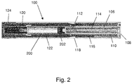
- Figure 2 is a section through an auto-injector 100 in an assembled state before activation and with a syringe 200 retained therein.
- the plunger 106 is received within the elongate member 110.
- the plunger 106 is a hollow tube with an open end at the rear and the drive spring 112 is received within the plunger 106.
- a first end of the drive spring 112 abuts a forward end of the plunger 106 and a second end of the drive spring 112 is fixed with respect to the rear cap at least during delivery of a medicament from the syringe.
- the drive spring 112 is coupled to an end of dose indicator 114, which in turn is coupled to the rear cap 104.
- the end of dose indicator provides a reaction component against which the drive spring 112 reacts. Expansion of the drive spring 112 drives the plunger 106 forwards into the barrel of the syringe 200.
- the auto-injector 100 also comprises a clutch 116, which is positioned around the elongate member 110. Before activation of the auto-injector 100, the clutch 116 is rotationally coupled to the plunger 106 and to the end of dose indicator 114. Rotation of the clutch 116 therefore causes rotation of the plunger 106 and the end of dose indicator 114. As explained below, on activation of the auto-injector 100, the clutch 116 rotates, thereby rotating the plunger 106 relative to the rear cap 104 to release the connection therebetween. Operation of the clutch 116, and of the end of dose indicator 114, is explained in more detail below.
- the auto-injector 100 also comprises a main body 118, which houses the firing mechanism 102, the syringe 200 and other features necessary for operation of the auto-injector 100.
- the main body 118 may comprise a plurality of separate parts.
- the main body 118 comprises a syringe locator, which in exemplary arrangements comprises one or more features for receiving and optionally retaining a syringe in position within the main body 118.
- the auto-injector also comprises a lockout spring 120 and lockout shroud 122, wherein the lockout spring 120 is configured on release thereof to displace the lockout shroud 122 axially forwards to cover a needle of the syringe.
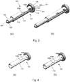
- a cap 124 also forms part of the auto-injector and covers a needle or forward end of the auto-injector prior to use.
- Figures 3a and 3b show perspective views of an assembly 300 for a firing mechanism.
- the assembly 300 comprises the rear cap 104 and the plunger 106.
- the plunger 106 is telescopically received within the elongate member 110.
- the assembly 300 also comprises a plunger driver to drive the plunger 106 axially forwards, which in the exemplary arrangements disclosed herein comprises a compression spring although the skilled person will understand that other arrangement are possible.
- the exemplary plunger 106 comprises a cylindrical tube that is open at a rear end and closed at a forward end.
- the forward end of the plunger 106 comprises a shoulder 302 and a projection 304 configured to engage a bung 202 in a syringe barrel.
- the plunger 106 also comprises a lug 306 configured to engage with any of a plurality of recesses 308a, 308b in the elongate member 110. In the exemplary arrangements of Figures 3a and 3b the lug 306 extends radially from on outer surface of the plunger 106.
- the elongate member 110 comprises an axial channel 310.
- the plurality of recesses 308a, 308b are formed in a sidewall of the channel 310. That is, the plurality of recesses 308a, 308b extend circumferentially (or transverse to the axial channel) around the outer wall of the elongate member 110. It is noted that while only two recesses 308a, 308b are shown in Figures 3a and 3b , more recesses (e.g. three - as shown in Figure 4 - or four) may be provided in the elongate member 110.
- the recess 308b comprises an angled rear surface and a front surface that is perpendicular to an axial direction (or longitudinal axis) of the auto-injector 100.
- the recesses 308a, 308b are configured to receive the lug 306 of the plunger 106.
- Figure 3a shows the lug 306 received in a rearward recess 308a and
- Figure 3b shows the lug 306 received in a forward recess 308b.
- the channel 310 and the recesses 308a, 308b are configured such that rotation of the plunger 106 relative to the elongate member 110 in a first direction moves the lug 306 into the recesses 308a, 308b and rotation in a second, opposite direction moves the lug 306 out of the recesses 308a, 308b.
- the axial length of the assembly 300 determines a start position of the forward end of the plunger 106 before release of the connection of the plunger 106 the elongate member 110. This can be seen in Figures 3a and 3b , which show the plunger 106 releasably connected to the elongate member 110 at different points, thereby controlling the overall axial length of the assembly 300.
- the plunger 106 is connected to the elongate member 110 at any of a plurality of positions on the elongate member 110 and/or the plunger 106 to alter a combined axial length of the plunger 106 and the elongate member 110.
- the connection may be made directly or indirectly through a plunger carrier, as explained below. In the example of Figures 3a and 3b , a direct connection is made.
- the plunger 106 may be received within the elongate member 110 such that the lug 306 is in the channel 310.
- the plunger 106 may then be displaced relative to the elongate member 110 until the lug 306 is aligned with one of the recesses 308a, 308b.
- the plunger 106 may then be rotated such that the lug is received within the one of the recesses 308a, 308b with which it was aligned.
- the force provided by the drive spring 112 retains the lug 306 within the recess 308a, 308b against the forward surface thereof.
- the combined axial length of the assembly i.e. of the rear cap 104 and the plunger 106) is increased in Figure 3b when compared to Figure 3a , in which the lug 306 is received within the rearward recess 308a.
- Figures 3a and 3b further illustrate a rear end of the end of dose indicator 114 which includes a lug 307 projecting radially outward.
- the lug 307 engages with the recess 308a formed in the sidewall of the channel 310, immediately behind the lug 306 of the plunger 106.
- the lug 307 also engages with the recess 308a whilst the lug 306 of the plunger 106 engages with the lower recess 308b as described above.
- Figures 4a and 4b show alternative rear caps 104 having three recesses 408a, 408b, 408c. It will be appreciated that other numbers of recesses may be used.
- the recesses 408a, 408b, 408c may be positioned at any point on the elongate member 110. In the exemplary arrangement of Figure 4b , the recesses 408b and 408c have been displaced forwards with respect to those in Figure 4a . It will be appreciated that the lug 307 of the end of dose indicator 114 is always retained, prior to activation, within the rearmost recess 408a, whilst the position of the lug 306 of the plunger 106 may be retained within that same recess or one of the lower recesses.
- the recess 308a presents a rear stop surface 311 extending in a generally circumferential direction.
- the circumferential extent of the stop surface 311 is such that combined rotation of the plunger 106 and end of dose indicator 114 to a position such that the plunger lug 306 is located within the channel 310 results in the continued blocking of the lug 307 (preventing rearward movement of the end of dose indicator 114).
- further rotation of the end of dose indicator 114 takes the lug 307 past the end of the stop surface 311 and aligns it with an effective upper extension 312 of the channel 310.
- the assembly comprising the plunger, the end of dose indicator and the rear cap is set using any of the methods and apparatus described herein.
- the plunger and end of dose indicator are connected to the elongate member of the rear cap.
- the connection is releasable in that, upon activation of the auto-injector, the connection is released to allow relative axial movement of the plunger and the rear cap.
- the connection may be made at any of a plurality of positions on the elongate member or the plunger. That is, one or both of the elongate member and the plunger may be configured to have a plurality of locations at which the connection may be made.
- the combined axial length of the plunger and the rear cap is set to the desired length based on a fill volume (or bung position) of a syringe that the auto-injector is intended for use with.
- the gap between the bung of the syringe, which sits at a position in the barrel that is dependent on the fill volume is controlled. That is, if the combined axial length of the plunger and the rear cap is extended then the auto-injector may be used for syringes having a smaller fill volume, or otherwise having a bung that is initially positioned further forwards within the barrel, e.g. if the barrel is of a greater diameter but the fill volume remains the same.
- the start position of a forward end of the plunger is adjusted during assembly.
- a user removes the cap 124 of the auto-injector 100, which in turn removes a rigid needle shield covering the needle. Removal of the cap exposes the lockout shroud 122, which protrudes from a forward end of the body 118.
- the user places a forward end of the lockout shroud 122 against an injection site and pushes the auto-injector 100 downwards onto the injection site. This action pushes the lockout shroud 122 rearwards within the auto-injector 100.
- the lockout shroud interacts with the clutch 116 to rotate it. This may be done by forcing a surface (or pip) of the lockout shroud 122 against an angled surface on the clutch 116, which translates the rearward motion of the lockout shroud 122 into rotational motion of the clutch 116.
- an insertion spring may be activated by the action of pushing the auto-injector 100 onto the injection site and the insertion spring may drive the syringe forwards within the device to insert the needle into the injection site.
- the force applied by the drive spring 112 acting against the bung may be used to insert the needle.
- the syringe may be fixed in relation to the injection device 100 and the force applied by the user when pushing the auto-injector 100 onto the injection site may insert the needle into the injection site.
- the clutch 116 may have an internal track located on an internal wall thereof and that receives a lug of the plunger 106 and a lug of the end of dose indicator 114. These lugs may be the same as the lugs 306, 307 described with reference to Figures 3a and 3b . Rotation of the plunger 106 with respect to the rear cap 104 releases the connection between the rear cap 104 and the plunger 106, allowing the plunger 106 to be driven forwards under force of the drive spring 112.
- this is provided by rotating the lug 306 of the plunger rod 106 out of whichever recess 308a, 308b, 408a-408c the lug 306 was positioned in and into the axial channel 310.
- the lug 306 is thereby allowed to travel forwards within the channel 310.
- Figure 6 illustrates the state of the device immediately following rotation of the lug 306 out of the recess 308a and into the channel 310. In this state, the lug 307 of the end of dose indicator 314 has been rotated to the same extent.
- the drive spring 112 then acts against the plunger 106 and the rear cap 104 via the end of dose indicator 114 which is prevented from moving rearwards by the stop surface 311. Because the rear cap 104 is fixed within the auto-injector 100, the force delivered by the drive spring 112 acts to drive the plunger 106 into the barrel of the syringe. Because the gap between the forward end of the plunger 106 and the bung 202 has been controlled during assembly, the plunger 106 does not accelerate above a safe velocity that would risk damage to the syringe 200 or harm or discomfort to the subject of the injection.
- Figure 7 illustrates subsequent series of steps that result in an end of dose indication being provided to a user.
Landscapes
- Health & Medical Sciences (AREA)
- Vascular Medicine (AREA)
- Engineering & Computer Science (AREA)
- Anesthesiology (AREA)
- Biomedical Technology (AREA)
- Heart & Thoracic Surgery (AREA)
- Hematology (AREA)
- Life Sciences & Earth Sciences (AREA)
- Animal Behavior & Ethology (AREA)
- General Health & Medical Sciences (AREA)
- Public Health (AREA)
- Veterinary Medicine (AREA)
- Infusion, Injection, And Reservoir Apparatuses (AREA)
Abstract
Description
- The invention relates to injection devices for delivering a fluid substance to a user or patient via a syringe and in particular to such devices having an end of dose indicator. In specific arrangements, the invention relates to auto-injectors for delivering the fluid under a force applied by a drive system.
- Injection devices are used for the convenient administration of medicaments to patients. For example, injection devices, which may be auto-injectors, may be used for providing a single metered dose of a medicament. Such devices may be either single use "disposable" devices in which the device is typically provided with a syringe already installed, and which is not user-replaceable, or "reusable" devices which allow the user to replace the syringe when the medicament has been used.
- It is noted that whilst the term "syringe" is used herein for clarity and consistency, this term is not intended to be limiting. In some arrangements the syringe may for example be a cartridge (which, for example, may be arranged to receive a disposable needle) or other medicament container. In some arrangements the syringe/cartridge/medicament container may be formed integrally with the (or part of the) injection device.
- Injection devices may be provided in the form of an auto-injector device, in which delivery of the medicament is automated and the device may also be arranged to automate the insertion of a needle into the skin prior to the delivery of the medicament. However, it is noted that the term auto-injector may encompass injection devices that automatically insert the needle and devices which require the user to manually insert the needle.
- Injection devices generally comprise a firing mechanism that is arranged to deliver a fluid from the syringe automatically under the force of a drive system, such as a drive spring. Optionally, injection devices may also comprise an insertion mechanism to displace the syringe within a housing of the injection device to cause needle penetration. The delivery arrangement generally acts via a plunger which includes a plunger and may also include or engage a piston (also referred to as a "bung") which is slidably provided within the syringe.
- Injection devices may be designed and manufactured to accommodate different syringes. This provides a device that may be adapted to carry and operate syringes with different features and/or characteristics, such as different fill volumes. It is desirable to improve the safety and operability of such devices.
- Injection devices of the autoinjector type do not necessarily provide a tactile indication to users when a dose has been completely delivered such as the user will experience when using a manual device. As such it is desirable to incorporate into injection devices of the autoinjector type a means for providing an end of dose indication.
- Methods and apparatus disclosed herein may be arranged to mitigate or solve one or more problems associated with the art, including those mentioned above and/or elsewhere herein.
- According to a first aspect of the present invention there is provided an injection device comprising a body for receiving a syringe, a firing mechanism comprising a reaction component, a plunger configured to be axially displaced in a forward direction relative to the reaction component, and a drive spring located between the reaction component and the plunger for driving the plunger forwards upon activation of the injection device, wherein said reaction component provides a reaction surface for the drive spring. The device further comprises a locking mechanism for locking the reaction component in a first axial position within the body, the locking mechanism being configured to release the reaction component upon a predefined forward movement of the plunger thereby allowing the reaction component to be driven in a rearward axial direction by the drive spring until it impacts against said body or a component secured to the body to thereby emit an audible indication of an end of dose.
- The locking mechanism may comprise a stop feature having a fixed axial position relate to said body, and a feature for causing a rotation of the reaction component within the body, substantially upon said predefined forward movement of the plunger, to move the reaction component out of a blocking engagement with said stop feature and thereby allow rearward movement of the reaction component.
- The device may comprise a rear cap fixed to a rear end of said body, the rear cap providing said component against which the reaction component impacts to emit an audible indication of an end of dose, wherein the feature for causing a rotation of the reaction component within the body comprises a clutch has a substantially fixed axial position, the clutch being rotatable within the body by axial movement of the plunger towards the end of a delivery stroke to thereby cause said rotation of the reaction component. The clutch may be a substantially cylindrical component within which said plunger, said delivery spring and said reaction component and are coaxially accommodated. The reaction component may comprise an elongate rod extending through the delivery spring and an enlarged head at a rearward end of the rod, wherein the head provides said reaction surface and a surface that impacts the rear cap.
- The end cap may comprise a skirt extending into the body from said rear end of the body and which defines a substantially longitudinally extending channel, said plunger and said reaction component being received within the skirt and being provided respectively with a plunger lug and a reaction component lug, said lugs being receivable within said channel to guide axial movement of the plunger and the reaction component.
- The skirt may further defining a recess extending from said channel in a substantially circumferential direction and within which said lugs are located prior to device activation, said clutch being rotatable within the body upon activation to move the lugs into the channel.
- The device may comprise a circumferential deviation of said channel rearwards of said recess in order to provide said stop feature, whereby the reaction component is prevented from moving rearward upon said activation but is permitted to move rearwards at the end of the plunger stroke.
- The device may comprise a lockout shroud extending from a forward end of said body and being configured to cause activation of the device when pressed into the body, wherein said lockout shroud causes activation of the device by rotating said clutch as the lockout shroud is pressed into the body to thereby move the lugs of the plunger and the reaction component out of said recess and into the channel.
- The drive spring may be a compression spring configured to expand upon activation of the device.
- Exemplary embodiments will be described herein with reference to the accompanying drawings, in which:
-
Figure 1 is an exploded view of an auto-injector; -
Figure 2 is a section through an auto-injector with a syringe fitted therein; -
Figures 3a and 3b show perspective views of exemplary firing mechanism assemblies; -
Figures 4a and 4b show perspective views of exemplary rear caps; -
Figure 5 illustrates a state of internal parts of the device prior to device activation; -
Figure 6 illustrates a state of internal parts of the device at an activation state and before forward movement of a device plunger commences; and -
Figure 7 in partial cross-section various states of the device during forward movement of the plunger. - In the following embodiments, the terms "forward" and "front" refer to the patient facing end of the injection device or component thereof. In other words, the front end of the injection device is the end proximal to the injection site during use. Likewise, the term "rear" refers to the non-patient end of the injection device assembly or component thereof. In other words, the term "rear" means distant or remote from the injection site during use.
- Many features of the exemplary arrangements disclosed herein are described as being "coupled" to other features. This term encompasses any coupling that results in the coupled features moving together in any direction, whether that be on a 1:1 basis or on some geared basis. The term "coupled" also encompasses any one of a connection between features, an abutment of one feature against another and an engagement of one feature with another, and such coupling may be direct or may be indirect, i.e. with a third feature therebetween.
-
Figure 1 shows an exploded view of an auto-injector 100. The auto-injector 100 comprises afiring assembly 102. The firing assembly comprises arear cap 104 and aplunger 106. Therear cap 104 comprises ahead 108 and anelongate member 110. Therear cap 104 and theplunger 106 are connected to each other such that before firing, relative axial movement between them is resisted or prevented. The connection between therear cap 104 and theplunger 106 is releasable such that after activation of the auto-injector 100, relative axial movement between them is permitted. The nature of the releasable connection is discussed in more detail below. - The
firing assembly 102 also comprises abiasing member 112 for driving theplunger 106 axially forwards and into a barrel of a syringe (shown inFigure 2 ) retained within the auto-injector 100. In one example thebiasing member 112 is a drive spring (e.g. a compression spring) and will be referred to as such throughout, although this should not be construed as limiting and the skilled person will appreciate that other means may be used to drive the plunger forwards. - In the example of
Figure 1 , theplunger 106 is telescopically received within theelongate member 110 of therear cap 104. Thedrive spring 112 is positioned between therear cap 104 and theplunger 106 such that they are biased in opposite axial directions relative to each other. This is best shown inFigure 2 , which is a section through an auto-injector 100 in an assembled state before activation and with asyringe 200 retained therein. Theplunger 106 is received within theelongate member 110. Theplunger 106 is a hollow tube with an open end at the rear and thedrive spring 112 is received within theplunger 106. A first end of thedrive spring 112 abuts a forward end of theplunger 106 and a second end of thedrive spring 112 is fixed with respect to the rear cap at least during delivery of a medicament from the syringe. In the example ofFigure 2 , thedrive spring 112 is coupled to an end ofdose indicator 114, which in turn is coupled to therear cap 104. The end of dose indicator provides a reaction component against which thedrive spring 112 reacts. Expansion of thedrive spring 112 drives theplunger 106 forwards into the barrel of thesyringe 200. - In
Figure 2 , a forward end of theplunger 106 is shown abutting abung 202. This will not always be the case, as discussed above. - The auto-
injector 100 also comprises a clutch 116, which is positioned around theelongate member 110. Before activation of the auto-injector 100, the clutch 116 is rotationally coupled to theplunger 106 and to the end ofdose indicator 114. Rotation of the clutch 116 therefore causes rotation of theplunger 106 and the end ofdose indicator 114. As explained below, on activation of the auto-injector 100, the clutch 116 rotates, thereby rotating theplunger 106 relative to therear cap 104 to release the connection therebetween. Operation of the clutch 116, and of the end ofdose indicator 114, is explained in more detail below. - The auto-
injector 100 also comprises amain body 118, which houses thefiring mechanism 102, thesyringe 200 and other features necessary for operation of the auto-injector 100. Themain body 118 may comprise a plurality of separate parts. Themain body 118 comprises a syringe locator, which in exemplary arrangements comprises one or more features for receiving and optionally retaining a syringe in position within themain body 118. - The auto-injector also comprises a
lockout spring 120 andlockout shroud 122, wherein thelockout spring 120 is configured on release thereof to displace thelockout shroud 122 axially forwards to cover a needle of the syringe. Acap 124 also forms part of the auto-injector and covers a needle or forward end of the auto-injector prior to use. -
Figures 3a and 3b show perspective views of anassembly 300 for a firing mechanism. Theassembly 300 comprises therear cap 104 and theplunger 106. Theplunger 106 is telescopically received within theelongate member 110. Theassembly 300 also comprises a plunger driver to drive theplunger 106 axially forwards, which in the exemplary arrangements disclosed herein comprises a compression spring although the skilled person will understand that other arrangement are possible. - The
exemplary plunger 106 comprises a cylindrical tube that is open at a rear end and closed at a forward end. The forward end of theplunger 106 comprises ashoulder 302 and aprojection 304 configured to engage abung 202 in a syringe barrel. Theplunger 106 also comprises alug 306 configured to engage with any of a plurality ofrecesses elongate member 110. In the exemplary arrangements ofFigures 3a and 3b thelug 306 extends radially from on outer surface of theplunger 106. - The
elongate member 110 comprises anaxial channel 310. The plurality ofrecesses channel 310. That is, the plurality ofrecesses elongate member 110. It is noted that while only tworecesses Figures 3a and 3b , more recesses (e.g. three - as shown inFigure 4 - or four) may be provided in theelongate member 110. Therecess 308b comprises an angled rear surface and a front surface that is perpendicular to an axial direction (or longitudinal axis) of the auto-injector 100. Therecesses lug 306 of theplunger 106.Figure 3a shows thelug 306 received in arearward recess 308a andFigure 3b shows thelug 306 received in aforward recess 308b. - The
channel 310 and therecesses plunger 106 relative to theelongate member 110 in a first direction moves thelug 306 into therecesses lug 306 out of therecesses - The
plunger 106 and therear cap 104, in particular theelongate member 110, define an axial length of theassembly 300. The axial length of theassembly 300 determines a start position of the forward end of theplunger 106 before release of the connection of theplunger 106 theelongate member 110. This can be seen inFigures 3a and 3b , which show theplunger 106 releasably connected to theelongate member 110 at different points, thereby controlling the overall axial length of theassembly 300. - During assembly, the
plunger 106 is connected to theelongate member 110 at any of a plurality of positions on theelongate member 110 and/or theplunger 106 to alter a combined axial length of theplunger 106 and theelongate member 110. The connection may be made directly or indirectly through a plunger carrier, as explained below. In the example ofFigures 3a and 3b , a direct connection is made. Theplunger 106 may be received within theelongate member 110 such that thelug 306 is in thechannel 310. Theplunger 106 may then be displaced relative to theelongate member 110 until thelug 306 is aligned with one of therecesses plunger 106 may then be rotated such that the lug is received within the one of therecesses drive spring 112 retains thelug 306 within therecess rear cap 104 and the plunger 106) is increased inFigure 3b when compared toFigure 3a , in which thelug 306 is received within therearward recess 308a. -
Figures 3a and 3b further illustrate a rear end of the end ofdose indicator 114 which includes alug 307 projecting radially outward. In the configuration ofFigure 3(a) thelug 307 engages with therecess 308a formed in the sidewall of thechannel 310, immediately behind thelug 306 of theplunger 106. In the configuration ofFigure 3(b) thelug 307 also engages with therecess 308a whilst thelug 306 of theplunger 106 engages with thelower recess 308b as described above. -
Figures 4a and 4b show alternativerear caps 104 having threerecesses recesses elongate member 110. In the exemplary arrangement ofFigure 4b , therecesses Figure 4a . It will be appreciated that thelug 307 of the end ofdose indicator 114 is always retained, prior to activation, within therearmost recess 408a, whilst the position of thelug 306 of theplunger 106 may be retained within that same recess or one of the lower recesses. - As best seen in the detail of
Figure 5 , therecess 308a (or 408a with reference toFigures 4a and 4b ) presents arear stop surface 311 extending in a generally circumferential direction. The circumferential extent of thestop surface 311 is such that combined rotation of theplunger 106 and end ofdose indicator 114 to a position such that theplunger lug 306 is located within thechannel 310 results in the continued blocking of the lug 307 (preventing rearward movement of the end of dose indicator 114). However, further rotation of the end ofdose indicator 114, as will be described below, takes thelug 307 past the end of thestop surface 311 and aligns it with an effectiveupper extension 312 of thechannel 310. - During assembly of the auto-injector, the assembly comprising the plunger, the end of dose indicator and the rear cap is set using any of the methods and apparatus described herein. The plunger and end of dose indicator are connected to the elongate member of the rear cap. The connection is releasable in that, upon activation of the auto-injector, the connection is released to allow relative axial movement of the plunger and the rear cap. Also, the connection may be made at any of a plurality of positions on the elongate member or the plunger. That is, one or both of the elongate member and the plunger may be configured to have a plurality of locations at which the connection may be made.
- Accordingly, the combined axial length of the plunger and the rear cap is set to the desired length based on a fill volume (or bung position) of a syringe that the auto-injector is intended for use with. In so doing, the gap between the bung of the syringe, which sits at a position in the barrel that is dependent on the fill volume, is controlled. That is, if the combined axial length of the plunger and the rear cap is extended then the auto-injector may be used for syringes having a smaller fill volume, or otherwise having a bung that is initially positioned further forwards within the barrel, e.g. if the barrel is of a greater diameter but the fill volume remains the same. The start position of a forward end of the plunger is adjusted during assembly.
- Once assembled, the user has no control over the combined length of the rear cap and the plunger. Operation of the auto-
injector 100 is described below using the reference numerals of the exemplary arrangement shown inFigures 1 to 3 , with reference to the further figures as appropriate. - In use, a user removes the
cap 124 of the auto-injector 100, which in turn removes a rigid needle shield covering the needle. Removal of the cap exposes thelockout shroud 122, which protrudes from a forward end of thebody 118. - The user places a forward end of the
lockout shroud 122 against an injection site and pushes the auto-injector 100 downwards onto the injection site. This action pushes thelockout shroud 122 rearwards within the auto-injector 100. The lockout shroud interacts with the clutch 116 to rotate it. This may be done by forcing a surface (or pip) of thelockout shroud 122 against an angled surface on the clutch 116, which translates the rearward motion of thelockout shroud 122 into rotational motion of the clutch 116. - In some arrangements, an insertion spring may be activated by the action of pushing the auto-
injector 100 onto the injection site and the insertion spring may drive the syringe forwards within the device to insert the needle into the injection site. In other arrangements, the force applied by thedrive spring 112 acting against the bung may be used to insert the needle. In yet further arrangements, the syringe may be fixed in relation to theinjection device 100 and the force applied by the user when pushing the auto-injector 100 onto the injection site may insert the needle into the injection site. - As the clutch 116 is rotationally coupled to the
plunger 106 and to the end ofdose indicator 114, rotation of the clutch 116 causes rotation of theplunger 106 and the end ofdose indicator 114. In some arrangements, the clutch 116 may have an internal track located on an internal wall thereof and that receives a lug of theplunger 106 and a lug of the end ofdose indicator 114. These lugs may be the same as thelugs Figures 3a and 3b . Rotation of theplunger 106 with respect to therear cap 104 releases the connection between therear cap 104 and theplunger 106, allowing theplunger 106 to be driven forwards under force of thedrive spring 112. In the examples ofFigures 1-4 , this is provided by rotating thelug 306 of theplunger rod 106 out of whicheverrecess lug 306 was positioned in and into theaxial channel 310. Thelug 306 is thereby allowed to travel forwards within thechannel 310. -
Figure 6 illustrates the state of the device immediately following rotation of thelug 306 out of therecess 308a and into thechannel 310. In this state, thelug 307 of the end of dose indicator 314 has been rotated to the same extent. - The
drive spring 112 then acts against theplunger 106 and therear cap 104 via the end ofdose indicator 114 which is prevented from moving rearwards by thestop surface 311. Because therear cap 104 is fixed within the auto-injector 100, the force delivered by thedrive spring 112 acts to drive theplunger 106 into the barrel of the syringe. Because the gap between the forward end of theplunger 106 and thebung 202 has been controlled during assembly, theplunger 106 does not accelerate above a safe velocity that would risk damage to thesyringe 200 or harm or discomfort to the subject of the injection. -
Figure 7 illustrates subsequent series of steps that result in an end of dose indication being provided to a user. - (a) The
plunger 106 has been driven forward to a position at which thelug 306 of the plunger meets arotation ramp 400 provided on an inner surface of the clutch 116. As thelug 306 remains confined within thechannel 310 of theelongate member 110, and therefore cannot rotate relative to theelongate member 110, thelug 306 causes the clutch 116 to rotate (counter-clockwise when viewed from the rear end of the device). Rotation of the clutch 116 by thelug 306 in turn rotates the end of dose indicator 114 (again in a counter-clockwise direction) due to engagement of the clutch with thelug 307. - (b) The
lug 307 is moved across the stop surface 311 (Figure 5 ) until the lug is free to move rearward into thechannel extension 312. This state is shown in the left view ofFigure 7b . The right view ofFigure 7b is a full cross-sectional view of the rear end of the device in this state. Part of thestop surface 311 may be slightly angled to encourage rotation of thelug 307 across the stop surface. - (c) As the
lug 307 is now free to move rearwardly along thechannel extension 312, the end ofdose indicator 114 is forced rearwards by the force exerted by thedrive spring 112 until an end of the end of dose indicator strikes an inner surface of thehead 108 of the rear cap. This impact results in an audible sound or click. - Referring again to
Figure 7a , it will be apparent that the final rotation of the clutch which results in rotation and release of the end of dose indicator occurs slightly ahead of the plunger bottoming out relative to the syringe. The audible click therefore occurs shortly in time ahead of the actual end of dose. However, given the auditory processing delay of the user, the click is perceived to occur at the actual end of dose point or slightly thereafter. - It will be appreciated by the person of skill in the art that various modifications may be made to the above described embodiments without departing from the scope of the present invention.
Claims (12)
- An injection device comprising:a body for receiving a syringe;a firing mechanism comprising a reaction component, a plunger configured to be axially displaced in a forward direction relative to the reaction component, and a drive spring located between the reaction component and the plunger for driving the plunger forwards upon activation of the injection device, wherein said reaction component provides a reaction surface for the drive spring; anda locking mechanism for locking the reaction component in a first axial position within the body, the locking mechanism being configured to release the reaction component upon a predefined forward movement of the plunger thereby allowing the reaction component to be driven in a rearward axial direction by the drive spring until it impacts against said body or a component secured to the body to thereby emit an audible indication of an end of dose.
- An injection device according to claim 1, wherein said locking mechanism comprises a stop feature having a fixed axial position relate to said body, and a feature for causing a rotation of the reaction component within the body, substantially upon said predefined forward movement of the plunger, to move the reaction component out of a blocking engagement with said stop feature and thereby allow rearward movement of the reaction component.
- An injection device according to claim 1 or 2 and comprising a rear cap fixed to a rear end of said body, the rear cap providing said component against which the reaction component impacts to emit an audible indication of an end of dose.
- An injection device according to claim 3 when appended to claim 2, wherein said feature for causing a rotation of the reaction component within the body comprises a clutch having a substantially fixed axial position, the clutch being rotatable within the body by axial movement of the plunger towards the end of a delivery stroke to thereby cause said rotation of the reaction component.
- An injection device according to claim 4, wherein said clutch is a substantially cylindrical component within which said plunger, said delivery spring and said reaction component and are coaxially accommodated.
- An injection device according to claim 4 or 5, wherein said reaction component comprises an elongate rod extending through the delivery spring and an enlarged head at a rearward end of the rod, wherein the head provides said reaction surface and a surface that impacts the rear cap.
- An injection device according to claim 6, wherein said end cap comprises a skirt extending into the body from said rear end of the body and which defines a substantially longitudinally extending channel, said plunger and said reaction component being received within the skirt and being provided respectively with a plunger lug and a reaction component lug, said lugs being receivable within said channel to guide axial movement of the plunger and the reaction component.
- An injection device according to claim 7, said skirt further defining a recess extending from said channel in a substantially circumferential direction and within which said lugs are located prior to device activation, said clutch being rotatable within the body upon activation to move the lugs into the channel.
- An injection device according to claim 8 and comprising a circumferential deviation of said channel rearwards of said recess in order to provide said stop feature, whereby the reaction component is prevented from moving rearward upon said activation but is permitted to move rearwards at the end of the plunger stroke.
- An injection device according to any one of the preceding claims and comprising a lockout shroud extending from a forward end of said body and being configured to cause activation of the device when pressed into the body.
- An injection device according to claim 10 when appended to claim 8, wherein said lockout shroud causes activation of the device by rotating said clutch as the lockout shroud is pressed into the body to thereby move the lugs of the plunger and the reaction component out of said recess and into the channel.
- An injection device according to any one of the preceding claims, wherein said drive spring is a compression spring configured to expand upon activation of the device.
Applications Claiming Priority (1)
| Application Number | Priority Date | Filing Date | Title |
|---|---|---|---|
| GB1815865.9A GB2577555A (en) | 2018-09-28 | 2018-09-28 | Injection device end of dose indicator |
Publications (2)
| Publication Number | Publication Date |
|---|---|
| EP3628347A1 true EP3628347A1 (en) | 2020-04-01 |
| EP3628347B1 EP3628347B1 (en) | 2021-02-24 |
Family
ID=67998223
Family Applications (1)
| Application Number | Title | Priority Date | Filing Date |
|---|---|---|---|
| EP19198490.5A Not-in-force EP3628347B1 (en) | 2018-09-28 | 2019-09-19 | Injection device and dose indicator |
Country Status (4)
| Country | Link |
|---|---|
| US (1) | US11369745B2 (en) |
| EP (1) | EP3628347B1 (en) |
| CN (1) | CN110960755B (en) |
| GB (1) | GB2577555A (en) |
Families Citing this family (3)
| Publication number | Priority date | Publication date | Assignee | Title |
|---|---|---|---|---|
| AU2020360255B2 (en) * | 2019-09-30 | 2026-03-19 | Amgen Inc. | Drug delivery device |
| JP2024502004A (en) | 2020-12-31 | 2024-01-17 | リジェネロン・ファーマシューティカルズ・インコーポレイテッド | Auto-injectors and related uses |
| CN120550256B (en) * | 2025-07-30 | 2025-10-03 | 苏州嘉树医疗科技有限公司 | Disposable injection pen and injection prompt structure thereof |
Citations (4)
| Publication number | Priority date | Publication date | Assignee | Title |
|---|---|---|---|---|
| EP2698179A1 (en) * | 2012-08-14 | 2014-02-19 | Sanofi-Aventis Deutschland GmbH | Injection device |
| EP3023114A1 (en) * | 2009-10-08 | 2016-05-25 | SHL Group AB | Medicament delivery device |
| WO2017032586A1 (en) * | 2015-08-24 | 2017-03-02 | Carebay Europe Ltd | Monitoring unit |
| US20170304541A1 (en) * | 2014-10-06 | 2017-10-26 | Carebay Europe Ltd. | Medicament Delivery Device |
Family Cites Families (9)
| Publication number | Priority date | Publication date | Assignee | Title |
|---|---|---|---|---|
| US8647309B2 (en) * | 2008-05-02 | 2014-02-11 | Sanofi-Aventis Deutschland Gmbh | Medication delivery device |
| WO2011101377A1 (en) * | 2010-02-18 | 2011-08-25 | Sanofi-Aventis Deutschland Gmbh | Auto-injector |
| EP2489390A1 (en) * | 2011-02-18 | 2012-08-22 | Sanofi-Aventis Deutschland GmbH | Detent mechanism |
| EP2489381A1 (en) * | 2011-02-18 | 2012-08-22 | Sanofi-Aventis Deutschland GmbH | Auto-injector |
| EP2583705A1 (en) * | 2011-10-21 | 2013-04-24 | Sanofi-Aventis Deutschland GmbH | Indicator arrangement for an auto-injector |
| US9962494B2 (en) * | 2013-11-22 | 2018-05-08 | Sanofi-Aventis Deutschland Gmbh | Drug delivery device with end of dose feedback |
| TW201603847A (en) * | 2014-07-01 | 2016-02-01 | 賽諾菲公司 | Injection device and assembly method |
| GB2530714A (en) * | 2014-08-20 | 2016-04-06 | Owen Mumford Ltd | Injection devices |
| TW201700118A (en) * | 2015-06-03 | 2017-01-01 | 賽諾菲阿凡提斯德意志有限公司 | Drug delivery device (3) |
-
2018
- 2018-09-28 GB GB1815865.9A patent/GB2577555A/en not_active Withdrawn
-
2019
- 2019-09-19 EP EP19198490.5A patent/EP3628347B1/en not_active Not-in-force
- 2019-09-26 CN CN201910922458.5A patent/CN110960755B/en not_active Expired - Fee Related
- 2019-09-27 US US16/586,469 patent/US11369745B2/en active Active
Patent Citations (4)
| Publication number | Priority date | Publication date | Assignee | Title |
|---|---|---|---|---|
| EP3023114A1 (en) * | 2009-10-08 | 2016-05-25 | SHL Group AB | Medicament delivery device |
| EP2698179A1 (en) * | 2012-08-14 | 2014-02-19 | Sanofi-Aventis Deutschland GmbH | Injection device |
| US20170304541A1 (en) * | 2014-10-06 | 2017-10-26 | Carebay Europe Ltd. | Medicament Delivery Device |
| WO2017032586A1 (en) * | 2015-08-24 | 2017-03-02 | Carebay Europe Ltd | Monitoring unit |
Also Published As
| Publication number | Publication date |
|---|---|
| US20200101230A1 (en) | 2020-04-02 |
| CN110960755B (en) | 2022-03-08 |
| US11369745B2 (en) | 2022-06-28 |
| EP3628347B1 (en) | 2021-02-24 |
| GB2577555A (en) | 2020-04-01 |
| CN110960755A (en) | 2020-04-07 |
Similar Documents
| Publication | Publication Date | Title |
|---|---|---|
| US20210361881A1 (en) | Injection device with commit feature | |
| JP6698861B2 (en) | Two body syringe carrier assembly with cushioning material | |
| US10722652B2 (en) | Automatic injection device with plunger velocity regulator | |
| JP4578484B2 (en) | Injection device | |
| US11992661B2 (en) | Injection device fill volume management | |
| EP3628347B1 (en) | Injection device and dose indicator | |
| US11648349B2 (en) | Injection device fill volume management | |
| EP3576816B1 (en) | A medicament delivery device | |
| US20210353860A1 (en) | Container holder for adapting smaller diameter container | |
| US20240091447A1 (en) | Injection device | |
| GB2606984A (en) | Injection device |
Legal Events
| Date | Code | Title | Description |
|---|---|---|---|
| PUAI | Public reference made under article 153(3) epc to a published international application that has entered the european phase |
Free format text: ORIGINAL CODE: 0009012 |
|
| STAA | Information on the status of an ep patent application or granted ep patent |
Free format text: STATUS: THE APPLICATION HAS BEEN PUBLISHED |
|
| AK | Designated contracting states |
Kind code of ref document: A1 Designated state(s): AL AT BE BG CH CY CZ DE DK EE ES FI FR GB GR HR HU IE IS IT LI LT LU LV MC MK MT NL NO PL PT RO RS SE SI SK SM TR |
|
| AX | Request for extension of the european patent |
Extension state: BA ME |
|
| STAA | Information on the status of an ep patent application or granted ep patent |
Free format text: STATUS: REQUEST FOR EXAMINATION WAS MADE |
|
| 17P | Request for examination filed |
Effective date: 20200420 |
|
| RBV | Designated contracting states (corrected) |
Designated state(s): AL AT BE BG CH CY CZ DE DK EE ES FI FR GB GR HR HU IE IS IT LI LT LU LV MC MK MT NL NO PL PT RO RS SE SI SK SM TR |
|
| GRAP | Despatch of communication of intention to grant a patent |
Free format text: ORIGINAL CODE: EPIDOSNIGR1 |
|
| STAA | Information on the status of an ep patent application or granted ep patent |
Free format text: STATUS: GRANT OF PATENT IS INTENDED |
|
| INTG | Intention to grant announced |
Effective date: 20200909 |
|
| GRAS | Grant fee paid |
Free format text: ORIGINAL CODE: EPIDOSNIGR3 |
|
| GRAA | (expected) grant |
Free format text: ORIGINAL CODE: 0009210 |
|
| STAA | Information on the status of an ep patent application or granted ep patent |
Free format text: STATUS: THE PATENT HAS BEEN GRANTED |
|
| AK | Designated contracting states |
Kind code of ref document: B1 Designated state(s): AL AT BE BG CH CY CZ DE DK EE ES FI FR GB GR HR HU IE IS IT LI LT LU LV MC MK MT NL NO PL PT RO RS SE SI SK SM TR |
|
| REG | Reference to a national code |
Ref country code: CH Ref legal event code: EP |
|
| REG | Reference to a national code |
Ref country code: AT Ref legal event code: REF Ref document number: 1363680 Country of ref document: AT Kind code of ref document: T Effective date: 20210315 |
|
| REG | Reference to a national code |
Ref country code: IE Ref legal event code: FG4D |
|
| REG | Reference to a national code |
Ref country code: DE Ref legal event code: R096 Ref document number: 602019002772 Country of ref document: DE |
|
| REG | Reference to a national code |
Ref country code: LT Ref legal event code: MG9D |
|
| REG | Reference to a national code |
Ref country code: NL Ref legal event code: MP Effective date: 20210224 |
|
| PG25 | Lapsed in a contracting state [announced via postgrant information from national office to epo] |
Ref country code: LT Free format text: LAPSE BECAUSE OF FAILURE TO SUBMIT A TRANSLATION OF THE DESCRIPTION OR TO PAY THE FEE WITHIN THE PRESCRIBED TIME-LIMIT Effective date: 20210224 Ref country code: PT Free format text: LAPSE BECAUSE OF FAILURE TO SUBMIT A TRANSLATION OF THE DESCRIPTION OR TO PAY THE FEE WITHIN THE PRESCRIBED TIME-LIMIT Effective date: 20210624 Ref country code: NO Free format text: LAPSE BECAUSE OF FAILURE TO SUBMIT A TRANSLATION OF THE DESCRIPTION OR TO PAY THE FEE WITHIN THE PRESCRIBED TIME-LIMIT Effective date: 20210524 Ref country code: GR Free format text: LAPSE BECAUSE OF FAILURE TO SUBMIT A TRANSLATION OF THE DESCRIPTION OR TO PAY THE FEE WITHIN THE PRESCRIBED TIME-LIMIT Effective date: 20210525 Ref country code: FI Free format text: LAPSE BECAUSE OF FAILURE TO SUBMIT A TRANSLATION OF THE DESCRIPTION OR TO PAY THE FEE WITHIN THE PRESCRIBED TIME-LIMIT Effective date: 20210224 Ref country code: BG Free format text: LAPSE BECAUSE OF FAILURE TO SUBMIT A TRANSLATION OF THE DESCRIPTION OR TO PAY THE FEE WITHIN THE PRESCRIBED TIME-LIMIT Effective date: 20210524 Ref country code: HR Free format text: LAPSE BECAUSE OF FAILURE TO SUBMIT A TRANSLATION OF THE DESCRIPTION OR TO PAY THE FEE WITHIN THE PRESCRIBED TIME-LIMIT Effective date: 20210224 |
|
| REG | Reference to a national code |
Ref country code: AT Ref legal event code: MK05 Ref document number: 1363680 Country of ref document: AT Kind code of ref document: T Effective date: 20210224 |
|
| PG25 | Lapsed in a contracting state [announced via postgrant information from national office to epo] |
Ref country code: SE Free format text: LAPSE BECAUSE OF FAILURE TO SUBMIT A TRANSLATION OF THE DESCRIPTION OR TO PAY THE FEE WITHIN THE PRESCRIBED TIME-LIMIT Effective date: 20210224 Ref country code: RS Free format text: LAPSE BECAUSE OF FAILURE TO SUBMIT A TRANSLATION OF THE DESCRIPTION OR TO PAY THE FEE WITHIN THE PRESCRIBED TIME-LIMIT Effective date: 20210224 Ref country code: LV Free format text: LAPSE BECAUSE OF FAILURE TO SUBMIT A TRANSLATION OF THE DESCRIPTION OR TO PAY THE FEE WITHIN THE PRESCRIBED TIME-LIMIT Effective date: 20210224 Ref country code: NL Free format text: LAPSE BECAUSE OF FAILURE TO SUBMIT A TRANSLATION OF THE DESCRIPTION OR TO PAY THE FEE WITHIN THE PRESCRIBED TIME-LIMIT Effective date: 20210224 Ref country code: PL Free format text: LAPSE BECAUSE OF FAILURE TO SUBMIT A TRANSLATION OF THE DESCRIPTION OR TO PAY THE FEE WITHIN THE PRESCRIBED TIME-LIMIT Effective date: 20210224 |
|
| PG25 | Lapsed in a contracting state [announced via postgrant information from national office to epo] |
Ref country code: IS Free format text: LAPSE BECAUSE OF FAILURE TO SUBMIT A TRANSLATION OF THE DESCRIPTION OR TO PAY THE FEE WITHIN THE PRESCRIBED TIME-LIMIT Effective date: 20210624 |
|
| PG25 | Lapsed in a contracting state [announced via postgrant information from national office to epo] |
Ref country code: AT Free format text: LAPSE BECAUSE OF FAILURE TO SUBMIT A TRANSLATION OF THE DESCRIPTION OR TO PAY THE FEE WITHIN THE PRESCRIBED TIME-LIMIT Effective date: 20210224 Ref country code: SM Free format text: LAPSE BECAUSE OF FAILURE TO SUBMIT A TRANSLATION OF THE DESCRIPTION OR TO PAY THE FEE WITHIN THE PRESCRIBED TIME-LIMIT Effective date: 20210224 Ref country code: CZ Free format text: LAPSE BECAUSE OF FAILURE TO SUBMIT A TRANSLATION OF THE DESCRIPTION OR TO PAY THE FEE WITHIN THE PRESCRIBED TIME-LIMIT Effective date: 20210224 Ref country code: EE Free format text: LAPSE BECAUSE OF FAILURE TO SUBMIT A TRANSLATION OF THE DESCRIPTION OR TO PAY THE FEE WITHIN THE PRESCRIBED TIME-LIMIT Effective date: 20210224 |
|
| REG | Reference to a national code |
Ref country code: DE Ref legal event code: R097 Ref document number: 602019002772 Country of ref document: DE |
|
| PG25 | Lapsed in a contracting state [announced via postgrant information from national office to epo] |
Ref country code: DK Free format text: LAPSE BECAUSE OF FAILURE TO SUBMIT A TRANSLATION OF THE DESCRIPTION OR TO PAY THE FEE WITHIN THE PRESCRIBED TIME-LIMIT Effective date: 20210224 Ref country code: SK Free format text: LAPSE BECAUSE OF FAILURE TO SUBMIT A TRANSLATION OF THE DESCRIPTION OR TO PAY THE FEE WITHIN THE PRESCRIBED TIME-LIMIT Effective date: 20210224 Ref country code: RO Free format text: LAPSE BECAUSE OF FAILURE TO SUBMIT A TRANSLATION OF THE DESCRIPTION OR TO PAY THE FEE WITHIN THE PRESCRIBED TIME-LIMIT Effective date: 20210224 |
|
| PLBE | No opposition filed within time limit |
Free format text: ORIGINAL CODE: 0009261 |
|
| STAA | Information on the status of an ep patent application or granted ep patent |
Free format text: STATUS: NO OPPOSITION FILED WITHIN TIME LIMIT |
|
| PG25 | Lapsed in a contracting state [announced via postgrant information from national office to epo] |
Ref country code: ES Free format text: LAPSE BECAUSE OF FAILURE TO SUBMIT A TRANSLATION OF THE DESCRIPTION OR TO PAY THE FEE WITHIN THE PRESCRIBED TIME-LIMIT Effective date: 20210224 Ref country code: AL Free format text: LAPSE BECAUSE OF FAILURE TO SUBMIT A TRANSLATION OF THE DESCRIPTION OR TO PAY THE FEE WITHIN THE PRESCRIBED TIME-LIMIT Effective date: 20210224 |
|
| 26N | No opposition filed |
Effective date: 20211125 |
|
| PG25 | Lapsed in a contracting state [announced via postgrant information from national office to epo] |
Ref country code: SI Free format text: LAPSE BECAUSE OF FAILURE TO SUBMIT A TRANSLATION OF THE DESCRIPTION OR TO PAY THE FEE WITHIN THE PRESCRIBED TIME-LIMIT Effective date: 20210224 |
|
| PG25 | Lapsed in a contracting state [announced via postgrant information from national office to epo] |
Ref country code: IT Free format text: LAPSE BECAUSE OF FAILURE TO SUBMIT A TRANSLATION OF THE DESCRIPTION OR TO PAY THE FEE WITHIN THE PRESCRIBED TIME-LIMIT Effective date: 20210224 |
|
| REG | Reference to a national code |
Ref country code: BE Ref legal event code: MM Effective date: 20210930 |
|
| PG25 | Lapsed in a contracting state [announced via postgrant information from national office to epo] |
Ref country code: IS Free format text: LAPSE BECAUSE OF FAILURE TO SUBMIT A TRANSLATION OF THE DESCRIPTION OR TO PAY THE FEE WITHIN THE PRESCRIBED TIME-LIMIT Effective date: 20210624 Ref country code: MC Free format text: LAPSE BECAUSE OF FAILURE TO SUBMIT A TRANSLATION OF THE DESCRIPTION OR TO PAY THE FEE WITHIN THE PRESCRIBED TIME-LIMIT Effective date: 20210224 |
|
| PG25 | Lapsed in a contracting state [announced via postgrant information from national office to epo] |
Ref country code: LU Free format text: LAPSE BECAUSE OF NON-PAYMENT OF DUE FEES Effective date: 20210919 Ref country code: IE Free format text: LAPSE BECAUSE OF NON-PAYMENT OF DUE FEES Effective date: 20210919 Ref country code: BE Free format text: LAPSE BECAUSE OF NON-PAYMENT OF DUE FEES Effective date: 20210930 |
|
| REG | Reference to a national code |
Ref country code: CH Ref legal event code: PL |
|
| PG25 | Lapsed in a contracting state [announced via postgrant information from national office to epo] |
Ref country code: CY Free format text: LAPSE BECAUSE OF FAILURE TO SUBMIT A TRANSLATION OF THE DESCRIPTION OR TO PAY THE FEE WITHIN THE PRESCRIBED TIME-LIMIT Effective date: 20210224 |
|
| P01 | Opt-out of the competence of the unified patent court (upc) registered |
Effective date: 20230530 |
|
| PG25 | Lapsed in a contracting state [announced via postgrant information from national office to epo] |
Ref country code: LI Free format text: LAPSE BECAUSE OF NON-PAYMENT OF DUE FEES Effective date: 20220930 Ref country code: HU Free format text: LAPSE BECAUSE OF FAILURE TO SUBMIT A TRANSLATION OF THE DESCRIPTION OR TO PAY THE FEE WITHIN THE PRESCRIBED TIME-LIMIT; INVALID AB INITIO Effective date: 20190919 Ref country code: CH Free format text: LAPSE BECAUSE OF NON-PAYMENT OF DUE FEES Effective date: 20220930 |
|
| PGFP | Annual fee paid to national office [announced via postgrant information from national office to epo] |
Ref country code: GB Payment date: 20230920 Year of fee payment: 5 |
|
| PGFP | Annual fee paid to national office [announced via postgrant information from national office to epo] |
Ref country code: FR Payment date: 20230928 Year of fee payment: 5 Ref country code: DE Payment date: 20230920 Year of fee payment: 5 |
|
| PG25 | Lapsed in a contracting state [announced via postgrant information from national office to epo] |
Ref country code: MK Free format text: LAPSE BECAUSE OF FAILURE TO SUBMIT A TRANSLATION OF THE DESCRIPTION OR TO PAY THE FEE WITHIN THE PRESCRIBED TIME-LIMIT Effective date: 20210224 |
|
| PG25 | Lapsed in a contracting state [announced via postgrant information from national office to epo] |
Ref country code: TR Free format text: LAPSE BECAUSE OF FAILURE TO SUBMIT A TRANSLATION OF THE DESCRIPTION OR TO PAY THE FEE WITHIN THE PRESCRIBED TIME-LIMIT Effective date: 20210224 |
|
| PG25 | Lapsed in a contracting state [announced via postgrant information from national office to epo] |
Ref country code: MT Free format text: LAPSE BECAUSE OF FAILURE TO SUBMIT A TRANSLATION OF THE DESCRIPTION OR TO PAY THE FEE WITHIN THE PRESCRIBED TIME-LIMIT Effective date: 20210224 |
|
| REG | Reference to a national code |
Ref country code: DE Ref legal event code: R119 Ref document number: 602019002772 Country of ref document: DE |
|
| GBPC | Gb: european patent ceased through non-payment of renewal fee |
Effective date: 20240919 |
|
| PG25 | Lapsed in a contracting state [announced via postgrant information from national office to epo] |
Ref country code: DE Free format text: LAPSE BECAUSE OF NON-PAYMENT OF DUE FEES Effective date: 20250401 |
|
| PG25 | Lapsed in a contracting state [announced via postgrant information from national office to epo] |
Ref country code: GB Free format text: LAPSE BECAUSE OF NON-PAYMENT OF DUE FEES Effective date: 20240919 |
|
| PG25 | Lapsed in a contracting state [announced via postgrant information from national office to epo] |
Ref country code: FR Free format text: LAPSE BECAUSE OF NON-PAYMENT OF DUE FEES Effective date: 20240930 |