EP3628191A1 - Mattress support for adding hospital bed functionality to an in-home bed - Google Patents
Mattress support for adding hospital bed functionality to an in-home bed Download PDFInfo
- Publication number
- EP3628191A1 EP3628191A1 EP19200203.8A EP19200203A EP3628191A1 EP 3628191 A1 EP3628191 A1 EP 3628191A1 EP 19200203 A EP19200203 A EP 19200203A EP 3628191 A1 EP3628191 A1 EP 3628191A1
- Authority
- EP
- European Patent Office
- Prior art keywords
- top plate
- mattress support
- mattress
- coupled
- bladder
- Prior art date
- Legal status (The legal status is an assumption and is not a legal conclusion. Google has not performed a legal analysis and makes no representation as to the accuracy of the status listed.)
- Withdrawn
Links
- 230000008878 coupling Effects 0.000 claims description 25
- 238000010168 coupling process Methods 0.000 claims description 25
- 238000005859 coupling reaction Methods 0.000 claims description 25
- 230000013011 mating Effects 0.000 description 7
- 210000004712 air sac Anatomy 0.000 description 4
- 230000000712 assembly Effects 0.000 description 2
- 238000000429 assembly Methods 0.000 description 2
- 239000002023 wood Substances 0.000 description 2
- 230000001419 dependent effect Effects 0.000 description 1
- 238000003780 insertion Methods 0.000 description 1
- 230000037431 insertion Effects 0.000 description 1
- 238000000034 method Methods 0.000 description 1
Images


Classifications
-
- A—HUMAN NECESSITIES
- A47—FURNITURE; DOMESTIC ARTICLES OR APPLIANCES; COFFEE MILLS; SPICE MILLS; SUCTION CLEANERS IN GENERAL
- A47C—CHAIRS; SOFAS; BEDS
- A47C20/00—Head-, foot- or like rests for beds, sofas or the like
- A47C20/04—Head-, foot- or like rests for beds, sofas or the like with adjustable inclination
- A47C20/048—Head-, foot- or like rests for beds, sofas or the like with adjustable inclination by fluid means
-
- A—HUMAN NECESSITIES
- A61—MEDICAL OR VETERINARY SCIENCE; HYGIENE
- A61G—TRANSPORT, PERSONAL CONVEYANCES, OR ACCOMMODATION SPECIALLY ADAPTED FOR PATIENTS OR DISABLED PERSONS; OPERATING TABLES OR CHAIRS; CHAIRS FOR DENTISTRY; FUNERAL DEVICES
- A61G7/00—Beds specially adapted for nursing; Devices for lifting patients or disabled persons
- A61G7/10—Devices for lifting patients or disabled persons, e.g. special adaptations of hoists thereto
- A61G7/1013—Lifting of patients by
- A61G7/1021—Inflatable cushions
-
- A—HUMAN NECESSITIES
- A47—FURNITURE; DOMESTIC ARTICLES OR APPLIANCES; COFFEE MILLS; SPICE MILLS; SUCTION CLEANERS IN GENERAL
- A47C—CHAIRS; SOFAS; BEDS
- A47C20/00—Head-, foot- or like rests for beds, sofas or the like
- A47C20/04—Head-, foot- or like rests for beds, sofas or the like with adjustable inclination
-
- A—HUMAN NECESSITIES
- A61—MEDICAL OR VETERINARY SCIENCE; HYGIENE
- A61G—TRANSPORT, PERSONAL CONVEYANCES, OR ACCOMMODATION SPECIALLY ADAPTED FOR PATIENTS OR DISABLED PERSONS; OPERATING TABLES OR CHAIRS; CHAIRS FOR DENTISTRY; FUNERAL DEVICES
- A61G7/00—Beds specially adapted for nursing; Devices for lifting patients or disabled persons
-
- A—HUMAN NECESSITIES
- A61—MEDICAL OR VETERINARY SCIENCE; HYGIENE
- A61G—TRANSPORT, PERSONAL CONVEYANCES, OR ACCOMMODATION SPECIALLY ADAPTED FOR PATIENTS OR DISABLED PERSONS; OPERATING TABLES OR CHAIRS; CHAIRS FOR DENTISTRY; FUNERAL DEVICES
- A61G7/00—Beds specially adapted for nursing; Devices for lifting patients or disabled persons
- A61G7/002—Beds specially adapted for nursing; Devices for lifting patients or disabled persons having adjustable mattress frame
-
- A—HUMAN NECESSITIES
- A61—MEDICAL OR VETERINARY SCIENCE; HYGIENE
- A61G—TRANSPORT, PERSONAL CONVEYANCES, OR ACCOMMODATION SPECIALLY ADAPTED FOR PATIENTS OR DISABLED PERSONS; OPERATING TABLES OR CHAIRS; CHAIRS FOR DENTISTRY; FUNERAL DEVICES
- A61G7/00—Beds specially adapted for nursing; Devices for lifting patients or disabled persons
- A61G7/05—Parts, details or accessories of beds
- A61G7/0507—Side-rails
- A61G7/0512—Side-rails characterised by customised length
- A61G7/0513—Side-rails characterised by customised length covering particular sections of the bed, e.g. one or more partial side-rail sections along the bed
-
- A—HUMAN NECESSITIES
- A61—MEDICAL OR VETERINARY SCIENCE; HYGIENE
- A61G—TRANSPORT, PERSONAL CONVEYANCES, OR ACCOMMODATION SPECIALLY ADAPTED FOR PATIENTS OR DISABLED PERSONS; OPERATING TABLES OR CHAIRS; CHAIRS FOR DENTISTRY; FUNERAL DEVICES
- A61G7/00—Beds specially adapted for nursing; Devices for lifting patients or disabled persons
- A61G7/05—Parts, details or accessories of beds
- A61G7/0507—Side-rails
- A61G7/0512—Side-rails characterised by customised length
- A61G7/0513—Side-rails characterised by customised length covering particular sections of the bed, e.g. one or more partial side-rail sections along the bed
- A61G7/0514—Side-rails characterised by customised length covering particular sections of the bed, e.g. one or more partial side-rail sections along the bed mounted to individual mattress supporting frame sections
-
- A—HUMAN NECESSITIES
- A61—MEDICAL OR VETERINARY SCIENCE; HYGIENE
- A61G—TRANSPORT, PERSONAL CONVEYANCES, OR ACCOMMODATION SPECIALLY ADAPTED FOR PATIENTS OR DISABLED PERSONS; OPERATING TABLES OR CHAIRS; CHAIRS FOR DENTISTRY; FUNERAL DEVICES
- A61G7/00—Beds specially adapted for nursing; Devices for lifting patients or disabled persons
- A61G7/05—Parts, details or accessories of beds
- A61G7/0507—Side-rails
- A61G7/0516—Side-rails with height adjustability
Definitions
- the present disclosure relates to a bed assembly for use during at-home care. More specifically, the present disclosure relates to a bed assembly that elevates the head section of the traditional consumer mattress.
- the present disclosure is related to a bed assembly. Specifically, the present disclosure relates to a bed assembly that is compatible with a traditional consumer bed and can enhance the traditional consumer bed so it provides features of a traditional hospital bed. Such features include the ability to elevate the head section of the traditional consumer mattress using a mattress support having inflatable air bladders.
- Extended hospitalization of a patient is an ongoing challenge due to the high cost incurred by the patient and the hospital. At-home care is also challenging due to the high cost, difficulty, and complexity of equipping the home for patient care. While several systems and methods exist for equipping the home for patient care, opportunity exists for continued development in this area.
- a mattress support is used on a larger (e.g., queen sized) mattress, the mattress support must be as wide as the entire mattress (e.g., 60").
- a mattress support that wide would be expensive to ship and challenging for a healthcare professional, family member, or patient to transport or lift.
- dividing that mattress support into two sections would make it difficult to place the mattress support under the mattress, as it could not be inserted in between the mattress and box springs from one side.
- connecting the components once under the mattress would be problematic.
- the present disclosure includes one or more of the following features alone or in any combination.
- a mattress support includes a base plate configured to be positioned on a box spring of a bed.
- a bladder may be coupled to a top surface of the base plate.
- a top plate may be coupled to a top surface of the bladder.
- a top surface of the top plate may be configured to support a mattress.
- the bladder may be inflatable to adjust a height of the top plate.
- the top plate may include a coupling mechanism that enables the mattress support to be folded.
- the top plate includes a first half coupled to a second half by the coupling mechanism.
- the bladder may include a first bladder coupled to the first half of the top plate and a second bladder coupled to the second half of the top plate.
- the base plate may include a first half coupled to the first bladder and a second half couple to the second bladder.
- a top surface of the first half of the top plate may be positioned adjacent to a top surface of the second half of the top plate.
- the first bladder and the first half of the base plate may be positioned adjacent the first half of the top plate and the second bladder and the second half of the base plate may be positioned adjacent the second half of the top plate.
- a first side panel may be coupled to the first half of the top plate.
- the first side panel may be configured to couple to a first side rail.
- a second side panel may be coupled to the second half of the top plate.
- the second side panel may be configured to couple to a second side rail.
- the bladder may be inflated to adjust an angle of the top plate relative to a longitudinal axis of the mattress support.
- the coupling mechanism includes an interlocking joint or a hinge.
- a side panel may be coupled to the top plate.
- the side panel may be configured to couple to a side rail.
- the side panel may include a first side panel coupled to a first side of the top plate.
- the first side panel may be configured to couple to a first side rail.
- a second side panel may be coupled to a second side of the top plate.
- the second side panel may be configured to couple to a second side rail.
- a runner may extend along the top surface of the top plate.
- the runner may extend laterally along the top surface of the top plate.
- a plurality of runners may extend laterally along the top surface of the top plate.
- a mattress support includes a base plate configured to be positioned on a box spring of a bed.
- the base plate may have a first half and a second half.
- a first elevation assembly may be coupled to the first half of the base plate and a second elevation assembly may be coupled to the second half of the base plate.
- a top plate may have a first half and a second half. The first half of the top plate may be coupled to the first elevation assembly and the second half of the top plate may be coupled to the second elevation assembly.
- a coupling mechanism may couple the first half of the top plate and the second half of the top plate to enable the mattress support to be folded.
- the first elevation assembly may be a first bladder and the second elevation assembly may be a second bladder.
- the first bladder and the second bladder may be inflated to adjust an angle of the top plate relative to a longitudinal axis of the mattress support.
- the coupling mechanism may include an interlocking joint or a hinge.
- a top surface of the first half of the top plate may be positioned adjacent to a top surface of the second half of the top plate.
- the first elevation assembly and the first half of the base plate may be positioned adjacent the first half of the top plate and the second elevation assembly and the second half of the base plate may be positioned adjacent the second half of the top plate.
- a first side panel may be coupled to the first half of the top plate.
- a second side panel may be coupled to the second half of the top plate.
- the first side panel may be configured to couple to a first side rail.
- the second side panel may be configured to couple to a second side rail.
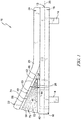
- FIG. 1 An illustrative bed assembly 10 is shown in Fig. 1 .
- the bed assembly 10 includes a frame 12 or box spring that is supported on the floor with legs 14.
- the frame 12 includes a head end 16 and a foot end 18.
- a mattress 20 is positioned on the frame 12 and extends between the head end 16 and the foot end 18 of the frame 12.
- a head end 22 of the mattress 20 is positioned at the head end 16 of the frame 12, and a foot end 24 of the mattress 20 is positioned at the foot end 18 of the frame 12.
- At least one of the head end 22 and the foot end 24 of the mattress 20 is moveable to angle relative to a longitudinal axis 26 of the frame 12. That is, the head end 22 and the foot end 24 of the mattress 20 may be raised relative to the frame 12.
- Fig. 1 illustrates the head end 22 in a raised position at an angle 28 relative to the longitudinal axis 26 of the frame 12.
- a mattress support 40 is positioned between the head end 16 of the frame 12 and the head end 22 of the mattress 20 to raise the head end 22 of the mattress 20.
- the mattress support 40 includes a base plate 42 having a bottom surface 44 and a top surface 46.
- the bottom surface 44 of the base plate 42 is positioned in contact with the frame 12.
- the top surface 46 of the base plate 42 faces upward from the frame 12.
- a top plate 50 is coupled to the base plate 42.
- An end 52 of the top plate 50 is coupled to an end 54 of the base plate 42 via a hinge 48 so that the top plate 50 is rotatable relative to the base plate 42 about the ends 52 and 54.
- the top plate 50 includes a top surface 56 and a bottom surface 58.
- the head end 22 of the mattress 20 is positioned on the top surface 56 of the top plate 50.
- the bottom surface 58 of the top plate 50 faces downward from the mattress 20.
- An elevation assembly 70 is positioned between the base plate 42 and the top plate 50.
- the elevation assembly 70 is coupled to the bottom surface 58 of the top plate 50 and the top surface 46 of the base plate 42.
- the elevation assembly 70 includes an air bladder 72 positioned within an expandable envelope 74.
- the elevation assembly 70 may include a plurality of air bladders 72 positioned within an expandable envelope 74. The air bladder 72 is inflatable to angle the top plate 50 relative to the base plate 42, thereby raising the head end 22 of the mattress 20.
- the envelope 74 includes a fixed end 76 at the ends 52 and 54 of the top plate 50 and the base plate 42, respectively.
- the envelope 74 also includes an expandable end 78 that is configured as an accordion sleeve that expands and contracts.
- the structure of the elevation assembly 70 may be embodied similarly to the z-plate assemblies 2044 and 2064 shown in PCT Publication No. WO2016/196403 , titled "Patient Support Apparatus.”
- the bladder 72 may be embodied similarly to the turn bladder assemblies 2034 and 2036 shown in the PCT Publication No. WO2016/196403 , titled “Patient Support Apparatus.”
- the PCT Publication No. WO2016/196403 titled “Patient Support Apparatus” is incorporated by reference herein for the disclosure of a structure suitable to lift portions of a mattress.
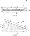
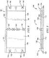
- the elevation assembly 70 raises and lowers the mattress support 40 between a lowered position 80, shown in Fig. 2 , and a raised position 82, shown in Fig. 3 .
- the mattress support 40 may be raised or lowered to any intermediate position between the lowered position 80 and the raised position 82.
- the mattress support 40 includes a left half 100 and a right half 102, shown in a flat configuration 108.
- the top plate 50 includes a left top plate 104 in the left half 100 of the mattress support 40 and a right top plate 106 in the right half 102 of the mattress support 40.
- the base plate 42 includes a left base plate 110 positioned below the left top plate 104 and a right base plate 112 positioned below the right top plate 106.
- a left elevation assembly 120 is coupled between the left top plate 104 and the left base plate 110.
- a right elevation assembly 122 is coupled between the right top plate 106 and the right base plate 112.
- the left elevation assembly 120 is configured to raise the left top plate 104 relative to the left base plate 110.
- the right elevation assembly 122 is configured to raise the right top plate 106 relative to the right base plate 112.
- the left elevation assembly 120 and the right elevation assembly 122 may be actuated simultaneously or separately.
- a left side panel 130 is coupled to the left top plate 104 on a left side 132 of the mattress support 40, and a right side panel 134 is coupled to the right top plate 106 on a right side 136 of the mattress support 40.
- the panels 130 and 134 are configured to receive a side rail. That is, a side rail bracket (not shown) is configured to couple to each of the panels 130 and 134.
- Each panel 130 and 134 includes apertures 140 extending from openings 142 formed in the panel 130, 134.
- the apertures 140 are configured to receive the side rail bracket.
- the panels 130 and 134 are configured to raise with the respective left top plate 104 and right top plate 106 to raise the side rail with the head end 22 of the mattress 20.
- a coupling mechanism 150 secures the left top plate 104 to the right top plate 106 so that the left half 100 and the right half 102 of the mattress support 40 can be folded into the folded configuration 152 shown in Fig. 6 .
- the top surface 56 of the left top plate 104 is positioned adjacent the top surface 56 of the right top plate 106.
- the left elevation assembly 120 and the left base plate 110 are positioned adjacent the left top plate 104, and the right elevation assembly 122 and the right base plate 112 are positioned adjacent the right top plate 106.
- the coupling mechanism 150 is a hinge 160 having a left flange 162 and a right flange 164 that are coupled so that the left flange 162 and the right flange 164 rotate relative to one another.
- the left flange 162 is coupled to the left top plate 104
- the right flange 164 is coupled to the right top plate 106.
- the hinge 160 enables the left top plate 104 to rotate relative to the right top plate 106 between the flat configuration 108 and the folded configuration 152.
- the coupling mechanism 150 is a mating hinge 170 having a left flange 172 and a right flange 174.
- the left flange 172 is configured to couple to the left top plate 104
- the right flange 174 is configured to couple to the right top plate 106.
- the left flange 172 includes a cylinder 180 having a pin 182
- the right flange 174 includes a cylinder 184 having an aperture 186.
- the aperture 186 is configured to receive the pin 182 to couple the left flange 172 to the right flange 174.
- the left top plate 104 may be coupled to the right top plate 106 by coupling the left flange 172 to the right flange 174.
- the left top plate 104 and the right top plate 106 may then be articulated between the flat configuration 108 and the folded configuration 152 about the mating hinge 170.
- the left flange 172 of the mating hinge 170 may be separated from the right flange 174 of the mating hinge 170 to separate the left top plate 104 and the right top plate 106.
- the left top plate 104 and the right top plate 106 may then be positioned in the folded configuration 152.
- the left top plate 104 is coupled to the right top plate 106 may mating the left flange 172 of the mating hinge 170 and the right flange 174 of the mating hinge 170.
- the coupling mechanism 150 is an interlocking joint 200.
- the interlocking joint 200 includes a notch 202 and a tab 204 formed on the left top plate 104, and a notch 206 and a tab 208 formed on the right top plate 106.
- the tab 204 is formed on an outer edge 210 of the left top plate 104.
- the notch 202 is positioned inward of and adjacent to the tab 204.
- the tab 208 is formed on an outer edge 212 of the right top plate 106.
- the notch 206 is positioned inward of and adjacent to the tab 208.
- the outer edge 210 of the left top plate 104 is configured to be positioned adjacent to the outer edge 212 of the right top plate 106, so that the notches 202, 206 and the tabs 204, 208 can be mated. That is, the tab 204 is positioned within the notch 206 and the tab 208 is positioned within the notch 202 to lock the left top plate 104 to the right top plate 106 to position the mattress support 40 in the flat configuration 108.
- the tabs 204, 208 are removed from the respective notches 202, 206 to separate the left half 100 and the right half 102 of the mattress support 40. When separated, the left half 100 and the right half 102 can be positioned in the folded configuration 152.
- the top plate 220 may be the left top plate 104 or the right top plate 106.
- the top plate 220 includes a top surface 222 having a plurality of runners 224 extending parallel to a lateral axis 226. Although two runners 224 are illustrated, the top plate 220 may have any number of runners 224, including only one or more than two.
- the runners 224 extend outward from the top surface 222.
- the runners 224 include a smooth top surface 228, e.g. a plastic surface, smoothed wood, or the like.
- Each runner 224 includes a pair of sloped sides 230.
- the mattress support 40 When positioning the mattress support 40 under the mattress 20, the mattress support 40 is inserted between the mattress 20 and the frame 12 from a side of the bed 10 so that the mattress support 40 is pushed under the mattress 20 along the lateral axis 226 of the mattress support 40.
- the sloped sides 230 of the runners 224 enable the mattress support 40 to be slid under the mattress 20.
- the top surface 228 of each runner 224 reduces a friction between the top plate 220 and the mattress 20 so that a patient, a family member, or a healthcare provider can slide the mattress support 40 under the mattress 20.
- the runners 224 increase a friction between the top plate 220 and the mattress 20 in a longitudinal direction. Accordingly, when the top plate 220 is actuated between the lowered position 80 and the raised position 82, the mattress 20 is prevented from sliding with respect to the mattress support 40.
- the base plate 240 may be either left base plate 110 or right base plate 112.
- the base plate 240 includes a bottom surface 242 having a plurality of runners 244 extending parallel to a lateral axis 246. Although a plurality of runners 244 are illustrated, the base plate 240 may have any number of runners 244 extending outwardly from the bottom surface 242.
- the runners 244 include a smooth bottom surface 248, e.g. a plastic surface, smoothed wood, or the like.
- each runner 244 reduces a friction between the base plate 240 and the frame 12 so that a patient, a family member, or a healthcare provider can slide the mattress support 40 under the mattress 20.
- the runners 244 increase a friction between the base plate 240 and the frame 12 in a longitudinal direction. Accordingly, when the top plate 220 is actuated between the lowered position 80 and the raised position 82, the mattress support 40 is prevented from sliding with respect to the frame 12.
Landscapes
- Health & Medical Sciences (AREA)
- Nursing (AREA)
- General Health & Medical Sciences (AREA)
- Life Sciences & Earth Sciences (AREA)
- Animal Behavior & Ethology (AREA)
- Public Health (AREA)
- Veterinary Medicine (AREA)
- Invalid Beds And Related Equipment (AREA)
Abstract
Description
- The present disclosure relates to a bed assembly for use during at-home care. More specifically, the present disclosure relates to a bed assembly that elevates the head section of the traditional consumer mattress.
- The present disclosure is related to a bed assembly. Specifically, the present disclosure relates to a bed assembly that is compatible with a traditional consumer bed and can enhance the traditional consumer bed so it provides features of a traditional hospital bed. Such features include the ability to elevate the head section of the traditional consumer mattress using a mattress support having inflatable air bladders.
- Extended hospitalization of a patient is an ongoing challenge due to the high cost incurred by the patient and the hospital. At-home care is also challenging due to the high cost, difficulty, and complexity of equipping the home for patient care. While several systems and methods exist for equipping the home for patient care, opportunity exists for continued development in this area. Where a mattress support is used on a larger (e.g., queen sized) mattress, the mattress support must be as wide as the entire mattress (e.g., 60"). Unfortunately, a mattress support that wide would be expensive to ship and challenging for a healthcare professional, family member, or patient to transport or lift. Additionally, dividing that mattress support into two sections would make it difficult to place the mattress support under the mattress, as it could not be inserted in between the mattress and box springs from one side. Moreover, connecting the components once under the mattress would be problematic.
- Another problem involved with mattress supports is that a mattress generally has the same amount of friction in any direction, making it difficult to slide the mattress support under the mattress. There is a need to simplify the insertion of the mattress support underneath the mattress, while also keeping the mattress support in place once inserted.
- The present disclosure includes one or more of the following features alone or in any combination.
- According to an aspect of the disclosed embodiments, a mattress support includes a base plate configured to be positioned on a box spring of a bed. A bladder may be coupled to a top surface of the base plate. A top plate may be coupled to a top surface of the bladder. A top surface of the top plate may be configured to support a mattress. The bladder may be inflatable to adjust a height of the top plate. The top plate may include a coupling mechanism that enables the mattress support to be folded.
- It may be desired that the top plate includes a first half coupled to a second half by the coupling mechanism. The bladder may include a first bladder coupled to the first half of the top plate and a second bladder coupled to the second half of the top plate. The base plate may include a first half coupled to the first bladder and a second half couple to the second bladder. When the mattress support is folded, a top surface of the first half of the top plate may be positioned adjacent to a top surface of the second half of the top plate. When the mattress is folded, the first bladder and the first half of the base plate may be positioned adjacent the first half of the top plate and the second bladder and the second half of the base plate may be positioned adjacent the second half of the top plate. A first side panel may be coupled to the first half of the top plate. The first side panel may be configured to couple to a first side rail. A second side panel may be coupled to the second half of the top plate. The second side panel may be configured to couple to a second side rail.
- In some embodiments, the bladder may be inflated to adjust an angle of the top plate relative to a longitudinal axis of the mattress support.
- It may be contemplated that the coupling mechanism includes an interlocking joint or a hinge.
- Alternatively or additionally, a side panel may be coupled to the top plate. The side panel may be configured to couple to a side rail. The side panel may include a first side panel coupled to a first side of the top plate. The first side panel may be configured to couple to a first side rail. A second side panel may be coupled to a second side of the top plate. The second side panel may be configured to couple to a second side rail.
- Optionally, a runner may extend along the top surface of the top plate. The runner may extend laterally along the top surface of the top plate. A plurality of runners may extend laterally along the top surface of the top plate.
- According to another aspect of the disclosed embodiments, a mattress support includes a base plate configured to be positioned on a box spring of a bed. The base plate may have a first half and a second half. A first elevation assembly may be coupled to the first half of the base plate and a second elevation assembly may be coupled to the second half of the base plate. A top plate may have a first half and a second half. The first half of the top plate may be coupled to the first elevation assembly and the second half of the top plate may be coupled to the second elevation assembly. A coupling mechanism may couple the first half of the top plate and the second half of the top plate to enable the mattress support to be folded.
- In some embodiments, the first elevation assembly may be a first bladder and the second elevation assembly may be a second bladder. The first bladder and the second bladder may be inflated to adjust an angle of the top plate relative to a longitudinal axis of the mattress support.
- Optionally, the coupling mechanism may include an interlocking joint or a hinge.
- It may be contemplated that, when the mattress support is folded, a top surface of the first half of the top plate may be positioned adjacent to a top surface of the second half of the top plate. When the mattress is folded, the first elevation assembly and the first half of the base plate may be positioned adjacent the first half of the top plate and the second elevation assembly and the second half of the base plate may be positioned adjacent the second half of the top plate.
- Alternatively or additionally, a first side panel may be coupled to the first half of the top plate. A second side panel may be coupled to the second half of the top plate. The first side panel may be configured to couple to a first side rail. The second side panel may be configured to couple to a second side rail.
- The invention will now be further described by way of example with reference to the accompanying drawings, in which:
-
Fig. 1 is side elevation view of a bed assembly having a mattress support positioned between a frame and a mattress; -
Fig. 2 is a side elevation view of the mattress support shown inFig. 1 in a lowered position; -
Fig. 3 is a side elevation view of the mattress support shown inFig. 1 in a raised position. -
Fig. 4 is a top plan view of the mattress support shown inFig. 1 ; -
Fig. 5 is a side elevation view of the mattress support shown inFig. 1 in a flat configuration; -
Fig. 6 is a side elevation view of the mattress support shown inFig. 1 in a folded configuration; -
Fig. 7 is a perspective view of an exemplary coupling mechanism that may be used with the mattress support shown inFig. 1 ; -
Fig. 8 is a perspective view of another exemplary coupling mechanism that may be used with the mattress support shown inFig. 1 ; -
Fig. 9 is a perspective view of yet another exemplary coupling mechanism that may be used with the mattress support shown inFig. 1 ; -
Fig. 10 is a perspective view of an exemplary top plate that may be used with the mattress support shown inFig. 1 ; -
Fig. 11 is a perspective view of an exemplary base plate that may be used with the mattress support shown inFig. 1 . - An
illustrative bed assembly 10 is shown inFig. 1 . Thebed assembly 10 includes aframe 12 or box spring that is supported on the floor withlegs 14. Theframe 12 includes ahead end 16 and afoot end 18. Amattress 20 is positioned on theframe 12 and extends between thehead end 16 and thefoot end 18 of theframe 12. Ahead end 22 of themattress 20 is positioned at thehead end 16 of theframe 12, and afoot end 24 of themattress 20 is positioned at thefoot end 18 of theframe 12. At least one of thehead end 22 and thefoot end 24 of themattress 20 is moveable to angle relative to alongitudinal axis 26 of theframe 12. That is, thehead end 22 and thefoot end 24 of themattress 20 may be raised relative to theframe 12.Fig. 1 illustrates thehead end 22 in a raised position at anangle 28 relative to thelongitudinal axis 26 of theframe 12. - A
mattress support 40 is positioned between thehead end 16 of theframe 12 and thehead end 22 of themattress 20 to raise thehead end 22 of themattress 20. Themattress support 40 includes abase plate 42 having abottom surface 44 and atop surface 46. Thebottom surface 44 of thebase plate 42 is positioned in contact with theframe 12. Thetop surface 46 of thebase plate 42 faces upward from theframe 12. Atop plate 50 is coupled to thebase plate 42. Anend 52 of thetop plate 50 is coupled to anend 54 of thebase plate 42 via ahinge 48 so that thetop plate 50 is rotatable relative to thebase plate 42 about theends top plate 50 includes atop surface 56 and abottom surface 58. Thehead end 22 of themattress 20 is positioned on thetop surface 56 of thetop plate 50. Thebottom surface 58 of thetop plate 50 faces downward from themattress 20. - An
elevation assembly 70 is positioned between thebase plate 42 and thetop plate 50. Theelevation assembly 70 is coupled to thebottom surface 58 of thetop plate 50 and thetop surface 46 of thebase plate 42. In the illustrative embodiment, theelevation assembly 70 includes anair bladder 72 positioned within anexpandable envelope 74. In some embodiments, theelevation assembly 70 may include a plurality ofair bladders 72 positioned within anexpandable envelope 74. Theair bladder 72 is inflatable to angle thetop plate 50 relative to thebase plate 42, thereby raising thehead end 22 of themattress 20. - Referring to
Figs. 2 and 3 , theenvelope 74 includes afixed end 76 at theends top plate 50 and thebase plate 42, respectively. Theenvelope 74 also includes anexpandable end 78 that is configured as an accordion sleeve that expands and contracts. In some embodiments, the structure of theelevation assembly 70 may be embodied similarly to the z-plate assemblies 2044 and 2064 shown inPCT Publication No. WO2016/196403 , titled "Patient Support Apparatus." Similarly, thebladder 72 may be embodied similarly to the turn bladder assemblies 2034 and 2036 shown in thePCT Publication No. WO2016/196403 , titled "Patient Support Apparatus." ThePCT Publication No. WO2016/196403 , titled "Patient Support Apparatus" is incorporated by reference herein for the disclosure of a structure suitable to lift portions of a mattress. - The
elevation assembly 70 raises and lowers themattress support 40 between a loweredposition 80, shown inFig. 2 , and a raisedposition 82, shown inFig. 3 . Notably, themattress support 40 may be raised or lowered to any intermediate position between the loweredposition 80 and the raisedposition 82. - Referring to
Figs. 4 and 5 , themattress support 40 includes aleft half 100 and aright half 102, shown in aflat configuration 108. Thetop plate 50 includes a lefttop plate 104 in theleft half 100 of themattress support 40 and a righttop plate 106 in theright half 102 of themattress support 40. Thebase plate 42 includes aleft base plate 110 positioned below the lefttop plate 104 and aright base plate 112 positioned below the righttop plate 106. Aleft elevation assembly 120 is coupled between the lefttop plate 104 and theleft base plate 110. Aright elevation assembly 122 is coupled between the righttop plate 106 and theright base plate 112. Theleft elevation assembly 120 is configured to raise the lefttop plate 104 relative to theleft base plate 110. Theright elevation assembly 122 is configured to raise the righttop plate 106 relative to theright base plate 112. Theleft elevation assembly 120 and theright elevation assembly 122 may be actuated simultaneously or separately. - A
left side panel 130 is coupled to the lefttop plate 104 on aleft side 132 of themattress support 40, and aright side panel 134 is coupled to the righttop plate 106 on aright side 136 of themattress support 40. Thepanels panels panel apertures 140 extending fromopenings 142 formed in thepanel apertures 140 are configured to receive the side rail bracket. Thepanels top plate 104 and righttop plate 106 to raise the side rail with thehead end 22 of themattress 20. - A
coupling mechanism 150 secures the lefttop plate 104 to the righttop plate 106 so that theleft half 100 and theright half 102 of themattress support 40 can be folded into the foldedconfiguration 152 shown inFig. 6 . In the foldedconfiguration 152, thetop surface 56 of the lefttop plate 104 is positioned adjacent thetop surface 56 of the righttop plate 106. Theleft elevation assembly 120 and theleft base plate 110 are positioned adjacent the lefttop plate 104, and theright elevation assembly 122 and theright base plate 112 are positioned adjacent the righttop plate 106. - Referring to
Fig. 7 , in some embodiments, thecoupling mechanism 150 is ahinge 160 having aleft flange 162 and aright flange 164 that are coupled so that theleft flange 162 and theright flange 164 rotate relative to one another. Theleft flange 162 is coupled to the lefttop plate 104, and theright flange 164 is coupled to the righttop plate 106. Thehinge 160 enables the lefttop plate 104 to rotate relative to the righttop plate 106 between theflat configuration 108 and the foldedconfiguration 152. - Referring to
Fig. 8 , in some embodiments, thecoupling mechanism 150 is amating hinge 170 having aleft flange 172 and aright flange 174. Theleft flange 172 is configured to couple to the lefttop plate 104, and theright flange 174 is configured to couple to the righttop plate 106. Theleft flange 172 includes acylinder 180 having apin 182, and theright flange 174 includes acylinder 184 having anaperture 186. Theaperture 186 is configured to receive thepin 182 to couple theleft flange 172 to theright flange 174. Accordingly, the lefttop plate 104 may be coupled to the righttop plate 106 by coupling theleft flange 172 to theright flange 174. The lefttop plate 104 and the righttop plate 106 may then be articulated between theflat configuration 108 and the foldedconfiguration 152 about themating hinge 170. In some embodiments, theleft flange 172 of themating hinge 170 may be separated from theright flange 174 of themating hinge 170 to separate the lefttop plate 104 and the righttop plate 106. The lefttop plate 104 and the righttop plate 106 may then be positioned in the foldedconfiguration 152. When articulating themattress support 40 to theflat configuration 108, the lefttop plate 104 is coupled to the righttop plate 106 may mating theleft flange 172 of themating hinge 170 and theright flange 174 of themating hinge 170. - Referring to
Fig. 9 , in some embodiments, thecoupling mechanism 150 is an interlockingjoint 200. The interlocking joint 200 includes anotch 202 and atab 204 formed on the lefttop plate 104, and anotch 206 and atab 208 formed on the righttop plate 106. Thetab 204 is formed on anouter edge 210 of the lefttop plate 104. Thenotch 202 is positioned inward of and adjacent to thetab 204. Thetab 208 is formed on anouter edge 212 of the righttop plate 106. Thenotch 206 is positioned inward of and adjacent to thetab 208. Theouter edge 210 of the lefttop plate 104 is configured to be positioned adjacent to theouter edge 212 of the righttop plate 106, so that thenotches tabs tab 204 is positioned within thenotch 206 and thetab 208 is positioned within thenotch 202 to lock the lefttop plate 104 to the righttop plate 106 to position themattress support 40 in theflat configuration 108. When articulating themattress support 40 to the foldedconfiguration 152, thetabs respective notches left half 100 and theright half 102 of themattress support 40. When separated, theleft half 100 and theright half 102 can be positioned in the foldedconfiguration 152. - Referring to
Fig. 10 , an embodiment of atop plate 220 for themattress support 40 is illustrated. Thetop plate 220 may be the lefttop plate 104 or the righttop plate 106. Thetop plate 220 includes atop surface 222 having a plurality ofrunners 224 extending parallel to alateral axis 226. Although tworunners 224 are illustrated, thetop plate 220 may have any number ofrunners 224, including only one or more than two. Therunners 224 extend outward from thetop surface 222. Therunners 224 include a smoothtop surface 228, e.g. a plastic surface, smoothed wood, or the like. Eachrunner 224 includes a pair of slopedsides 230. When positioning themattress support 40 under themattress 20, themattress support 40 is inserted between themattress 20 and theframe 12 from a side of thebed 10 so that themattress support 40 is pushed under themattress 20 along thelateral axis 226 of themattress support 40. The slopedsides 230 of therunners 224 enable themattress support 40 to be slid under themattress 20. Thetop surface 228 of eachrunner 224 reduces a friction between thetop plate 220 and themattress 20 so that a patient, a family member, or a healthcare provider can slide themattress support 40 under themattress 20. - Notably, when the
mattress support 40 is positioned under themattress 20, therunners 224 increase a friction between thetop plate 220 and themattress 20 in a longitudinal direction. Accordingly, when thetop plate 220 is actuated between the loweredposition 80 and the raisedposition 82, themattress 20 is prevented from sliding with respect to themattress support 40. - An embodiment of a
base plate 240 for themattress support 40 is illustrated inFig. 11 . Thebase plate 240 may be eitherleft base plate 110 orright base plate 112. Thebase plate 240 includes abottom surface 242 having a plurality ofrunners 244 extending parallel to alateral axis 246. Although a plurality ofrunners 244 are illustrated, thebase plate 240 may have any number ofrunners 244 extending outwardly from thebottom surface 242. Therunners 244 include asmooth bottom surface 248, e.g. a plastic surface, smoothed wood, or the like. - The
bottom surface 248 of eachrunner 244 reduces a friction between thebase plate 240 and theframe 12 so that a patient, a family member, or a healthcare provider can slide themattress support 40 under themattress 20. Notably, when themattress support 40 is positioned under themattress 20, therunners 244 increase a friction between thebase plate 240 and theframe 12 in a longitudinal direction. Accordingly, when thetop plate 220 is actuated between the loweredposition 80 and the raisedposition 82, themattress support 40 is prevented from sliding with respect to theframe 12. - Although this disclosure refers to multiple embodiments, it will be appreciated that features of each embodiment may be utilized with other embodiments described herein.
- Although this disclosure refers to specific embodiments, it will be understood by those skilled in the art that various changes in form and detail may be made.
- Embodiments of the invention can be described with reference to the following numbered clauses, with preferred features laid out in the dependent clauses:
- 1. A mattress support comprising:
- a base plate configured to be positioned on a box spring of a bed,
- a bladder coupled to a top surface of the base plate,
- a top plate coupled to a top surface of the bladder, a top surface of the top plate being configured to support a mattress,
- wherein the bladder is inflatable to adjust a height of the top plate, and wherein the top plate includes a coupling mechanism that enables the mattress support to be folded.
- 2. The mattress support of clause 1, wherein:
- the top plate includes a first half coupled to a second half by the coupling mechanism,
- the bladder includes a first bladder coupled to the first half of the top plate and a second bladder coupled to the second half of the top plate, and
- the base plate includes a first half coupled to the first bladder and a second half couple to the second bladder.
- 3. The mattress support of clause 2, wherein, when the mattress support is folded, a top surface of the first half of the top plate is positioned adjacent to a top surface of the second half of the top plate.
- 4. The mattress support of clause 3, wherein, when the mattress is folded, the first bladder and the first half of the base plate are positioned adjacent the first half of the top plate and the second bladder and the second half of the base plate are positioned adjacent the second half of the top plate.
- 5. The mattress of any one of clauses 2 to 4, further comprising:
- a first side panel coupled to the first half of the top plate, the first side panel being configured to couple to a first side rail, and
- a second side panel coupled to the second half of the top plate, the second side panel being configured to couple to a second side rail.
- 6. The mattress support of any one of clauses 1 to 4, further comprising a side panel coupled to the top plate.
- 7. The mattress support of clause 6, wherein the side panel is configured to couple to a side rail.
- 8. The mattress support of either clause 6 or clause 7, wherein the side panel includes
a first side panel coupled to a first side of the top plate, the first side panel being configured to couple to a first side rail, and
a second side panel coupled to a second side of the top plate, the second side panel being configured to couple to a second side rail. - 9. The mattress support of any preceding clause , wherein the bladder is inflated to adjust an angle of the top plate relative to a longitudinal axis of the mattress support.
- 10. The mattress support of any preceding clause, wherein the coupling mechanism includes an interlocking joint.
- 11. The mattress support of any preceding clause, wherein the coupling mechanism includes a hinge.
- 12. The mattress support of any preceding clause, further comprising a runner extending along the top surface of the top plate.
- 13. The mattress support of
clause 12, wherein the runner extends laterally along the top surface of the top plate. - 14. The mattress support of
clause 12, further comprising a plurality of runners extending laterally along the top surface of the top plate. - 15. A mattress support comprising:
- a base plate configured to be positioned on a box spring of a bed, the base plate having a first half and a second half,
- a first elevation assembly coupled to the first half of the base plate and a second elevation assembly coupled to the second half of the base plate,
- a top plate having a first half and a second half, the first half of the top plate coupled to the first elevation assembly and the second half of the top plate coupled to the second elevation assembly,
- a coupling mechanism coupling the first half of the top plate and the second half of the top plate to enable the mattress support to be folded.
- 16. The mattress support of clause 15, wherein the first elevation assembly is a first bladder and the second elevation assembly is a second bladder.
- 17. The mattress support of
clause 16, wherein the first bladder and the second bladder are inflated to adjust an angle of the top plate relative to a longitudinal axis of the mattress support. - 18. The mattress support of any one of clauses 15 to 17, wherein, when the mattress support is folded, a top surface of the first half of the top plate is positioned adjacent to a top surface of the second half of the top plate.
- 19. The mattress support of
clause 18, wherein, when the mattress is folded, the first elevation assembly and the first half of the base plate are positioned adjacent the first half of the top plate and the second elevation assembly and the second half of the base plate are positioned adjacent the second half of the top plate. - 20. The mattress of any one of clauses 15 to 20, further comprising:
- a first side panel coupled to the first half of the top plate, and
- a second side panel coupled to the second half of the top plate.
- 21. The mattress support of
clause 20, wherein:- the first side panel is configured to couple to a first side rail, and
- the second side panel is configured to couple to a second side rail.
- 22. The mattress support of any one of clauses 15 to 21, wherein the coupling mechanism includes an interlocking joint.
- 23. The mattress support of any one of clauses 15 to 21, wherein the coupling mechanism includes a hinge.
- 24. The mattress support of any one of clauses 15 to 23, further comprising a runner extending along the top surface of the top plate.
- 25. The mattress support of
clause 24, wherein the runner extends laterally along the top surface of the top plate. - 26. The mattress support of clause 15, further comprising a plurality of runners extending laterally along the top surface of the top plate.
Claims (14)
- A mattress support comprising:a base plate configured to be positioned on a box spring of a bed,a bladder coupled to a top surface of the base plate,a top plate coupled to a top surface of the bladder, a top surface of the top plate being configured to support a mattress,wherein the bladder is inflatable to adjust a height of the top plate, and wherein the top plate includes a coupling mechanism that enables the mattress support to be folded.
- The mattress support of claim 1, wherein:the top plate includes a first half coupled to a second half by the coupling mechanism,the bladder includes a first bladder coupled to the first half of the top plate and a second bladder coupled to the second half of the top plate, andthe base plate includes a first half coupled to the first bladder and a second half couple to the second bladder.
- The mattress support of claim 2, wherein, when the mattress support is folded, a top surface of the first half of the top plate is positioned adjacent to a top surface of the second half of the top plate.
- The mattress support of claim 3, wherein, when the mattress is folded, the first bladder and the first half of the base plate are positioned adjacent the first half of the top plate and the second bladder and the second half of the base plate are positioned adjacent the second half of the top plate.
- The mattress of any one of claims 2 to 4, further comprising:a first side panel coupled to the first half of the top plate, the first side panel being configured to couple to a first side rail, anda second side panel coupled to the second half of the top plate, the second side panel being configured to couple to a second side rail.
- The mattress support of any one of claims 1 to 4, further comprising a side panel coupled to the top plate.
- The mattress support of claim 6, wherein the side panel is configured to couple to a side rail.
- The mattress support of either claim 6 or claim 7, wherein the side panel includes
a first side panel coupled to a first side of the top plate, the first side panel being configured to couple to a first side rail, and
a second side panel coupled to a second side of the top plate, the second side panel being configured to couple to a second side rail. - The mattress support of any preceding claim, wherein the bladder is inflated to adjust an angle of the top plate relative to a longitudinal axis of the mattress support.
- The mattress support of any preceding claim, wherein the coupling mechanism includes an interlocking joint.
- The mattress support of any preceding claim, wherein the coupling mechanism includes a hinge.
- The mattress support of any preceding claim, further comprising a runner extending along the top surface of the top plate.
- The mattress support of claim 12, wherein the runner extends laterally along the top surface of the top plate.
- The mattress support of claim 12, further comprising a plurality of runners extending laterally along the top surface of the top plate.
Applications Claiming Priority (1)
| Application Number | Priority Date | Filing Date | Title |
|---|---|---|---|
| US201862739340P | 2018-09-30 | 2018-09-30 |
Publications (1)
| Publication Number | Publication Date |
|---|---|
| EP3628191A1 true EP3628191A1 (en) | 2020-04-01 |
Family
ID=68084664
Family Applications (1)
| Application Number | Title | Priority Date | Filing Date |
|---|---|---|---|
| EP19200203.8A Withdrawn EP3628191A1 (en) | 2018-09-30 | 2019-09-27 | Mattress support for adding hospital bed functionality to an in-home bed |
Country Status (3)
| Country | Link |
|---|---|
| US (1) | US11229568B2 (en) |
| EP (1) | EP3628191A1 (en) |
| CN (1) | CN211408323U (en) |
Families Citing this family (4)
| Publication number | Priority date | Publication date | Assignee | Title |
|---|---|---|---|---|
| US11470977B2 (en) | 2019-06-04 | 2022-10-18 | Hill-Rom Services, Inc. | Mattress support |
| US12593925B1 (en) | 2025-03-06 | 2026-04-07 | Travis R. Lewis | Bed sheet retention systems, and system components |
| EP4622507A1 (en) | 2022-11-21 | 2025-10-01 | Lewis, Travis, R. | Bed sheet retention systems and methods of making and using the same |
| CN116426385A (en) * | 2023-06-13 | 2023-07-14 | 北京大学深圳医院(北京大学深圳临床医学院) | Cell culture apparatus and cell culture method |
Citations (5)
| Publication number | Priority date | Publication date | Assignee | Title |
|---|---|---|---|---|
| DE1987293U (en) * | 1968-06-12 | Albert Vogtle S. Co 7332 Eislmgen | Air bellows for backs and head supports on beds, etc. | |
| JPS5438512U (en) * | 1977-08-19 | 1979-03-14 | ||
| JPH01238859A (en) * | 1988-03-18 | 1989-09-25 | Sanei Seisakusho:Kk | Bed |
| JPH04297257A (en) * | 1991-03-27 | 1992-10-21 | Koshin Rubber Kk | Nursing instrument |
| WO2016196403A1 (en) | 2015-05-29 | 2016-12-08 | Hill-Rom Services, Inc. | Patient support apparatus |
Family Cites Families (110)
| Publication number | Priority date | Publication date | Assignee | Title |
|---|---|---|---|---|
| US948644A (en) | 1908-06-23 | 1910-02-08 | Andrew Bjornstad | Mattress. |
| US1610898A (en) | 1923-10-05 | 1926-12-14 | Cleveland R Steiner | Pneumatic mattress |
| US2612645A (en) | 1949-09-13 | 1952-10-07 | Boland Gus Leslie | Reclining air cushion |
| US2887692A (en) | 1956-05-23 | 1959-05-26 | Gosman Clarence Berveir | Inflatable cushion or the like |
| GB1126364A (en) | 1965-10-18 | 1968-09-05 | Uniroyal Ltd | An inflatable cushion, seat, mattress or other like article |
| US3392412A (en) | 1967-01-12 | 1968-07-16 | Aymar Julian Robert | Adjustable bedrest |
| US3606623A (en) | 1970-01-09 | 1971-09-21 | Surgical Dynamics Inc | Adjustable bedrest with improved bellows structure |
| US3667075A (en) | 1970-02-24 | 1972-06-06 | Wesley D Ballard | Mattress spring bellows assembly as for hospitals, and the like |
| US3781928A (en) | 1971-04-05 | 1974-01-01 | Erik Pettersson | Device for raising the head end and/or foot end of a bed |
| US4150284A (en) | 1977-04-28 | 1979-04-17 | Texas Instruments Incorporated | Medical patient condition monitoring system |
| US4151407A (en) | 1977-04-28 | 1979-04-24 | Texas Instruments Incorporated | Low-power, infrared information transmission system |
| US4165125A (en) | 1977-06-08 | 1979-08-21 | National Seating Company | Slipover headrest pillow assembly |
| US4142263A (en) | 1977-11-25 | 1979-03-06 | Maine Ideas Incorporated | Bed-mattress elevating system and the like |
| US4216462A (en) | 1978-03-06 | 1980-08-05 | General Electric Company | Patient monitoring and data processing system |
| US4183015A (en) | 1978-06-26 | 1980-01-08 | Hill-Rom Company, Inc. | Side guard for bed including means for controlling remote electrical devices |
| US4228426A (en) | 1978-09-29 | 1980-10-14 | Roberts William A | Hospital bed monitor |
| US4225953A (en) | 1978-09-29 | 1980-09-30 | Simon William F | Personnel locator |
| US4237344A (en) | 1979-04-20 | 1980-12-02 | Hospital Communication Systems, Inc. | Rapid response health care communications system |
| US4331953A (en) | 1979-12-26 | 1982-05-25 | The Boeing Company | Communication system for use in hazardous confined areas |
| US4309783A (en) | 1980-02-06 | 1982-01-12 | Teledyne Industries, Inc. | Adjustably conformable bed |
| US4298863A (en) | 1980-02-10 | 1981-11-03 | St. Anthony Hospital Systems | Portable patient call |
| US5062151A (en) | 1983-01-13 | 1991-10-29 | Fisher Berkeley Corporation | Communication system |
| US4601064A (en) | 1983-01-13 | 1986-07-15 | Fisher Berkeley Corporation | Communication system |
| US4527298A (en) | 1982-03-18 | 1985-07-09 | Moulton Lee A | Electro pneumatic bed |
| US4649385A (en) | 1982-08-13 | 1987-03-10 | Teloc R & D Ltd. | Electronic locating system for persons receiving telephone calls |
| JPS5993524U (en) | 1982-12-15 | 1984-06-25 | 狩野 千世子 | Air mat type bed operated by computer |
| US4598275A (en) | 1983-05-09 | 1986-07-01 | Marc Industries Incorporated | Movement monitor |
| US4577185A (en) | 1983-07-29 | 1986-03-18 | Saint Margaret Hospital | Construction for alerting health-care professionals |
| US4554693A (en) | 1983-12-19 | 1985-11-26 | American Fast Print Limited | Mattress, box springs fabric |
| US4593273A (en) | 1984-03-16 | 1986-06-03 | Narcisse Bernadine O | Out-of-range personnel monitor and alarm |
| US4578671A (en) | 1984-12-05 | 1986-03-25 | International Business Machines Corp. | Remote indicating low battery voltage enunciator method and apparatus |
| US4680790A (en) | 1985-08-22 | 1987-07-14 | Joerns Healthcare, Inc. | Bedside control module for healthcare stations and the like |
| US5103108A (en) | 1985-10-17 | 1992-04-07 | Crimmins James W | Distributed infrared communication system |
| US4967195A (en) | 1986-05-08 | 1990-10-30 | Shipley Robert T | Hospital signaling and communications system |
| US4955000A (en) | 1986-07-17 | 1990-09-04 | Nac Engineering And Marketing, Inc. | Ultrasonic personnel location identification system |
| US4814751A (en) | 1987-02-27 | 1989-03-21 | Wildlife Materials, Inc. | Patient tracking system |
| US4839932A (en) | 1987-05-26 | 1989-06-20 | Williamson Robert M | Adjustable bed system |
| US4850040A (en) | 1987-07-01 | 1989-07-18 | Inncom International, Inc. | Infrared remote control system for activating and deactivating one or more devices in a single enclosed space |
| EP0340325B1 (en) | 1988-05-05 | 1991-02-20 | Hewlett-Packard GmbH | Digitally addressable electronic device |
| US4877288A (en) | 1988-09-06 | 1989-10-31 | Susan Lee | Lounge chair cover |
| US4998939A (en) | 1988-09-28 | 1991-03-12 | R & P Joint Venture | Hospital bed with guard rail actuated safety apparatus |
| US5153584A (en) | 1989-03-17 | 1992-10-06 | Cardiac Evaluation Center, Inc. | Miniature multilead biotelemetry and patient location system |
| US5124991A (en) | 1989-03-30 | 1992-06-23 | Photonics Corporation | Error correction for infrared data communication |
| US4932089A (en) | 1989-08-02 | 1990-06-12 | Laviero Frank D | Beach pillow |
| US4990892A (en) | 1989-08-07 | 1991-02-05 | Westcom, A Division Of Westside Communications Of Jacksonville, Inc. | Personnel locator system |
| US4998095A (en) | 1989-10-19 | 1991-03-05 | Specific Cruise Systems, Inc. | Emergency transmitter system |
| US5036852A (en) | 1989-12-08 | 1991-08-06 | Leishman Mark L | Medical equipment monitor apparatus and method |
| US5012539A (en) | 1990-02-13 | 1991-05-07 | Grigg Ellen S | Inflatable multi-purpose medical support pillow |
| US5086290A (en) | 1990-03-08 | 1992-02-04 | Murray Shawn G | Mobile perimeter monitoring system |
| US5060174A (en) | 1990-04-18 | 1991-10-22 | Biomechanics Corporation Of America | Method and apparatus for evaluating a load bearing surface such as a seat |
| US5144284A (en) | 1991-05-22 | 1992-09-01 | Hammett Rawlings H | Patient-monitoring bed covering device |
| US5253656A (en) | 1991-05-23 | 1993-10-19 | Rincoe Richard G | Apparatus and method for monitoring contact pressure between body parts and contact surfaces |
| US5137033A (en) | 1991-07-15 | 1992-08-11 | Norton John L | Patient monitoring device |
| US5184112A (en) | 1991-09-11 | 1993-02-02 | Gaymar Industries, Inc. | Bed patient position monitor |
| US5269388A (en) | 1991-11-12 | 1993-12-14 | Stress-Tek, Inc. | Weighing bed |
| US5170522A (en) | 1991-12-16 | 1992-12-15 | Select Comfort Corporation | Air adjustable bed |
| US5415167A (en) | 1992-01-10 | 1995-05-16 | Wilk; Peter J. | Medical system and associated method for automatic diagnosis and treatment |
| US5195198A (en) | 1992-01-15 | 1993-03-23 | Stryker Corporation | Fail-safe bed motion control circuit having a microprocessor |
| US5276432A (en) | 1992-01-15 | 1994-01-04 | Stryker Corporation | Patient exit detection mechanism for hospital bed |
| US5353012A (en) | 1992-05-14 | 1994-10-04 | Bartronix, Inc. | Bed position and activity sensing apparatus |
| US5577278A (en) | 1992-07-22 | 1996-11-26 | Princeton Products Inc. | Portable, integrated, universally adjustable position control system |
| US5311625A (en) | 1992-07-22 | 1994-05-17 | Truman Products | Portable, integrated, universally adjustable position control system |
| WO1994014128A2 (en) | 1992-12-11 | 1994-06-23 | Siemens Medical Systems, Inc. | Docking station for a patient monitoring system |
| US5838223A (en) | 1993-07-12 | 1998-11-17 | Hill-Rom, Inc. | Patient/nurse call system |
| US5345630A (en) | 1993-07-15 | 1994-09-13 | Jack Healy | Quick inflatable air mattress |
| US5715548A (en) | 1994-01-25 | 1998-02-10 | Hill-Rom, Inc. | Chair bed |
| US5490295A (en) | 1994-04-15 | 1996-02-13 | Boyd; Dennis | Water mattress and air mattress construction |
| CA2125300C (en) | 1994-05-11 | 1999-10-12 | Douglas J. Ballantyne | Method and apparatus for the electronic distribution of medical information and patient services |
| US5432967A (en) | 1994-06-20 | 1995-07-18 | Raftery Design, Inc. | Multiple position support cushion |
| US5528783A (en) * | 1994-07-11 | 1996-06-25 | Kunz; Richard D. | Inflatable head and torso support |
| US6125350A (en) | 1995-06-02 | 2000-09-26 | Software For Surgeons | Medical information log system |
| US7017208B2 (en) | 1995-08-04 | 2006-03-28 | Hill-Rom Services, Inc. | Hospital bed |
| US5942986A (en) | 1995-08-09 | 1999-08-24 | Cedars-Sinai Medical Center | System and method for automatic critical event notification |
| US5944659A (en) | 1995-11-13 | 1999-08-31 | Vitalcom Inc. | Architecture for TDMA medical telemetry system |
| US5621931A (en) | 1995-12-12 | 1997-04-22 | Hamilton; Samantha | Mattress stabilizing bedskirt assembly having detachably attachable skirt components |
| US5936539A (en) | 1996-03-19 | 1999-08-10 | Siemens Medical Systems, Inc. | Method and apparatus for automatic configuration of a network node |
| US5877675A (en) | 1996-08-29 | 1999-03-02 | Jansys, Inc. | Wireless healthcare communication system |
| US6097308A (en) | 1996-12-04 | 2000-08-01 | Data Critical Corp. | Pager to computer link apparatus |
| US5933488A (en) | 1997-04-18 | 1999-08-03 | Siemens Information | Automated method and arrangement for integrating a telephone system with an announcement system |
| US5844488A (en) | 1997-09-23 | 1998-12-01 | Musick; Jeff L. | Bed sensor and alarm |
| US5963137A (en) | 1998-02-10 | 1999-10-05 | Waters, Sr.; Joe Cleveland | Alarm device for monitoring an individual's movement and/or need for assistance |
| US6111509A (en) | 1998-02-26 | 2000-08-29 | Bed-Check Corporation | Microprocessor based bed patient monitor |
| US6142592A (en) | 1998-05-19 | 2000-11-07 | Endress & Hauser Gmbh & Co Kg | Instrument system |
| US6093146A (en) | 1998-06-05 | 2000-07-25 | Matsushita Electric Works, Ltd. | Physiological monitoring |
| US6009873A (en) | 1998-08-27 | 2000-01-04 | Neviaser; Thomas J. | Bed sore treatment and prevention method and apparatus |
| US6131219A (en) | 1999-03-03 | 2000-10-17 | Roberts; Janet H. | Inflatable pillow |
| US6133837A (en) | 1999-03-05 | 2000-10-17 | Hill-Rom, Inc. | Patient position system and method for a support surface |
| US6208250B1 (en) | 1999-03-05 | 2001-03-27 | Hill-Rom, Inc. | Patient position detection apparatus for a bed |
| JP2001095858A (en) * | 1999-03-25 | 2001-04-10 | Matsushita Seiko Co Ltd | Body moving device |
| JP2001095857A (en) * | 1999-03-25 | 2001-04-10 | Matsushita Seiko Co Ltd | Body supporting device and its usage |
| CA2311187A1 (en) | 1999-08-12 | 2001-02-12 | Hill-Rom, Inc. | Ambulatory assist arm for a bed |
| CA2762006C (en) | 2000-11-07 | 2013-05-21 | Tempur World, Inc. | Therapeutic mattress assembly |
| EP1421458B1 (en) | 2001-08-03 | 2010-04-07 | Hill-Rom Services, Inc. | Patient point-of-care computer system |
| US6739005B2 (en) | 2001-09-04 | 2004-05-25 | Banyan Licensing Lc | Bed with adjustable elevation components |
| US6684425B2 (en) | 2002-02-14 | 2004-02-03 | Edmund Scott Davis | Mattress retainer for adjustable bed |
| US20030196270A1 (en) | 2002-04-04 | 2003-10-23 | Banyan Licensing Lc | Inflatable bed support |
| JP4712385B2 (en) | 2002-09-06 | 2011-06-29 | ヒル−ロム サービシーズ,インコーポレイティド | Hospital bed |
| US7231681B2 (en) * | 2003-01-24 | 2007-06-19 | Victor M. Kasatshko | Multiple position air mattress system |
| US7319386B2 (en) | 2004-08-02 | 2008-01-15 | Hill-Rom Services, Inc. | Configurable system for alerting caregivers |
| US7852208B2 (en) | 2004-08-02 | 2010-12-14 | Hill-Rom Services, Inc. | Wireless bed connectivity |
| US7690059B2 (en) | 2005-12-19 | 2010-04-06 | Stryker Corporation | Hospital bed |
| US7028350B1 (en) | 2004-12-07 | 2006-04-18 | Woodlark Circle, Inc. | Lifting cushion and method for transferring a patient from a chair |
| US20060117482A1 (en) | 2004-12-07 | 2006-06-08 | Branson Gregory W | Touch screen control for lateral rotation of a hospital bed mattress |
| US20060230539A1 (en) | 2005-04-14 | 2006-10-19 | Goodman Bruce H | Mattress elevating foundation apparatus |
| US20080147442A1 (en) | 2006-12-18 | 2008-06-19 | General Electric Company | Smart bed system and apparatus |
| GB2461449B (en) | 2007-03-21 | 2012-07-11 | Gianna Muollo | Inflatable bed with abdomen receiving cavity |
| US20130232698A1 (en) | 2012-03-08 | 2013-09-12 | Billy Walter Ward | Systems and methods for mattress lifting to aid bed-making |
| US20150359351A1 (en) | 2013-01-28 | 2015-12-17 | Tempur-Pedic Management, Llc | Mattress assembly |
| US10045715B2 (en) | 2015-04-27 | 2018-08-14 | Hill-Rom Services, Inc. | Self-compensating bed scale system for removable components |
| US10137044B2 (en) | 2015-05-14 | 2018-11-27 | Hill-Rom Services, Inc. | Patient support apparatus with sensor assembly |
-
2019
- 2019-09-26 US US16/583,315 patent/US11229568B2/en active Active
- 2019-09-27 EP EP19200203.8A patent/EP3628191A1/en not_active Withdrawn
- 2019-09-30 CN CN201921658214.2U patent/CN211408323U/en not_active Expired - Fee Related
Patent Citations (5)
| Publication number | Priority date | Publication date | Assignee | Title |
|---|---|---|---|---|
| DE1987293U (en) * | 1968-06-12 | Albert Vogtle S. Co 7332 Eislmgen | Air bellows for backs and head supports on beds, etc. | |
| JPS5438512U (en) * | 1977-08-19 | 1979-03-14 | ||
| JPH01238859A (en) * | 1988-03-18 | 1989-09-25 | Sanei Seisakusho:Kk | Bed |
| JPH04297257A (en) * | 1991-03-27 | 1992-10-21 | Koshin Rubber Kk | Nursing instrument |
| WO2016196403A1 (en) | 2015-05-29 | 2016-12-08 | Hill-Rom Services, Inc. | Patient support apparatus |
Also Published As
| Publication number | Publication date |
|---|---|
| US20200100968A1 (en) | 2020-04-02 |
| US11229568B2 (en) | 2022-01-25 |
| CN211408323U (en) | 2020-09-04 |
Similar Documents
| Publication | Publication Date | Title |
|---|---|---|
| US11229568B2 (en) | Mattress support for adding hospital bed functionality to an in-home bed | |
| US10188567B2 (en) | Hospital chair beds with extendable/retractable foot sections | |
| AU2007207359B2 (en) | Articulating bed | |
| US11140995B2 (en) | Collapsible bed frame | |
| US8393279B2 (en) | Modular folding table | |
| US6691345B2 (en) | Lifting mechanism for liftable side rails for a lying table such as a bed | |
| US20050210588A1 (en) | Platform for adjustable height bed | |
| US7496979B2 (en) | Patient table with footrest extension | |
| US6564404B1 (en) | Liftable side rail for a lying table such as a bed | |
| US20050076440A1 (en) | Adjustable bed | |
| US20130055502A1 (en) | Long term care bed | |
| US20130312186A1 (en) | Patient support apparatus with movable siderail assembly | |
| CN110520092B (en) | Hospital chair bed with deployable/retractable foot section | |
| US20190133331A1 (en) | Split adjustable mattress foundation for multiple users | |
| US11400001B2 (en) | Method and apparatus for upgrading a bed to include moveable components | |
| EP2366371B1 (en) | Siderail assembly | |
| US8381664B2 (en) | Foldable table | |
| US20160061242A1 (en) | Bi-directional bed rail assembly | |
| US11930933B2 (en) | Adjustable bed base with incline feature | |
| US5608930A (en) | Foldable bed | |
| US20150040802A1 (en) | Expandable and collapsible table with nesting leaves | |
| US9572736B2 (en) | Adjustable bed with improved shear reducing mechanism | |
| CN109350405B (en) | Mattress | |
| KR20200004217A (en) | Chair combined table | |
| EP1053735B1 (en) | A side rail assembly for a bed or the like |
Legal Events
| Date | Code | Title | Description |
|---|---|---|---|
| PUAI | Public reference made under article 153(3) epc to a published international application that has entered the european phase |
Free format text: ORIGINAL CODE: 0009012 |
|
| STAA | Information on the status of an ep patent application or granted ep patent |
Free format text: STATUS: THE APPLICATION HAS BEEN PUBLISHED |
|
| AK | Designated contracting states |
Kind code of ref document: A1 Designated state(s): AL AT BE BG CH CY CZ DE DK EE ES FI FR GB GR HR HU IE IS IT LI LT LU LV MC MK MT NL NO PL PT RO RS SE SI SK SM TR |
|
| AX | Request for extension of the european patent |
Extension state: BA ME |
|
| STAA | Information on the status of an ep patent application or granted ep patent |
Free format text: STATUS: REQUEST FOR EXAMINATION WAS MADE |
|
| 17P | Request for examination filed |
Effective date: 20201001 |
|
| RBV | Designated contracting states (corrected) |
Designated state(s): AL AT BE BG CH CY CZ DE DK EE ES FI FR GB GR HR HU IE IS IT LI LT LU LV MC MK MT NL NO PL PT RO RS SE SI SK SM TR |
|
| STAA | Information on the status of an ep patent application or granted ep patent |
Free format text: STATUS: THE APPLICATION HAS BEEN WITHDRAWN |
|
| 18W | Application withdrawn |
Effective date: 20220327 |